WO2018186245A1 - 連結具、雄型クリップ、シートカバー、及びシート - Google Patents
連結具、雄型クリップ、シートカバー、及びシート Download PDFInfo
- Publication number
- WO2018186245A1 WO2018186245A1 PCT/JP2018/012611 JP2018012611W WO2018186245A1 WO 2018186245 A1 WO2018186245 A1 WO 2018186245A1 JP 2018012611 W JP2018012611 W JP 2018012611W WO 2018186245 A1 WO2018186245 A1 WO 2018186245A1
- Authority
- WO
- WIPO (PCT)
- Prior art keywords
- clip
- wall
- male clip
- male
- female
- Prior art date
- Legal status (The legal status is an assumption and is not a legal conclusion. Google has not performed a legal analysis and makes no representation as to the accuracy of the status listed.)
- Ceased
Links
Images



Classifications
-
- B—PERFORMING OPERATIONS; TRANSPORTING
- B68—SADDLERY; UPHOLSTERY
- B68G—METHODS, EQUIPMENT, OR MACHINES FOR USE IN UPHOLSTERING; UPHOLSTERY NOT OTHERWISE PROVIDED FOR
- B68G7/00—Making upholstery
- B68G7/12—Other elements specially adapted for fastening, fixing, or finishing, in upholstery work
-
- A—HUMAN NECESSITIES
- A47—FURNITURE; DOMESTIC ARTICLES OR APPLIANCES; COFFEE MILLS; SPICE MILLS; SUCTION CLEANERS IN GENERAL
- A47C—CHAIRS; SOFAS; BEDS
- A47C31/00—Details or accessories for chairs, beds, or the like, not provided for in other groups of this subclass, e.g. upholstery fasteners, mattress protectors, stretching devices for mattress nets
- A47C31/02—Upholstery attaching means
- A47C31/023—Upholstery attaching means connecting upholstery to frames, e.g. by hooks, clips, snap fasteners, clamping means or the like
-
- B—PERFORMING OPERATIONS; TRANSPORTING
- B60—VEHICLES IN GENERAL
- B60N—SEATS SPECIALLY ADAPTED FOR VEHICLES; VEHICLE PASSENGER ACCOMMODATION NOT OTHERWISE PROVIDED FOR
- B60N2/00—Seats specially adapted for vehicles; Arrangement or mounting of seats in vehicles
- B60N2/58—Seat coverings
- B60N2/5816—Seat coverings attachments thereof
- B60N2/5825—Seat coverings attachments thereof by hooks, staples, clips, snap fasteners or the like
-
- F—MECHANICAL ENGINEERING; LIGHTING; HEATING; WEAPONS; BLASTING
- F16—ENGINEERING ELEMENTS AND UNITS; GENERAL MEASURES FOR PRODUCING AND MAINTAINING EFFECTIVE FUNCTIONING OF MACHINES OR INSTALLATIONS; THERMAL INSULATION IN GENERAL
- F16B—DEVICES FOR FASTENING OR SECURING CONSTRUCTIONAL ELEMENTS OR MACHINE PARTS TOGETHER, e.g. NAILS, BOLTS, CIRCLIPS, CLAMPS, CLIPS OR WEDGES; JOINTS OR JOINTING
- F16B2/00—Friction-grip releasable fastenings
- F16B2/20—Clips, i.e. with gripping action effected solely by the inherent resistance to deformation of the material of the fastening
- F16B2/22—Clips, i.e. with gripping action effected solely by the inherent resistance to deformation of the material of the fastening of resilient material, e.g. rubbery material
-
- F—MECHANICAL ENGINEERING; LIGHTING; HEATING; WEAPONS; BLASTING
- F16—ENGINEERING ELEMENTS AND UNITS; GENERAL MEASURES FOR PRODUCING AND MAINTAINING EFFECTIVE FUNCTIONING OF MACHINES OR INSTALLATIONS; THERMAL INSULATION IN GENERAL
- F16B—DEVICES FOR FASTENING OR SECURING CONSTRUCTIONAL ELEMENTS OR MACHINE PARTS TOGETHER, e.g. NAILS, BOLTS, CIRCLIPS, CLAMPS, CLIPS OR WEDGES; JOINTS OR JOINTING
- F16B5/00—Joining sheets or plates, e.g. panels, to one another or to strips or bars parallel to them
- F16B5/06—Joining sheets or plates, e.g. panels, to one another or to strips or bars parallel to them by means of clamps or clips
- F16B5/0607—Joining sheets or plates, e.g. panels, to one another or to strips or bars parallel to them by means of clamps or clips joining sheets or plates to each other
- F16B5/0621—Joining sheets or plates, e.g. panels, to one another or to strips or bars parallel to them by means of clamps or clips joining sheets or plates to each other in parallel relationship
- F16B5/0664—Joining sheets or plates, e.g. panels, to one another or to strips or bars parallel to them by means of clamps or clips joining sheets or plates to each other in parallel relationship at least one of the sheets or plates having integrally formed or integrally connected snap-in-features
-
- F—MECHANICAL ENGINEERING; LIGHTING; HEATING; WEAPONS; BLASTING
- F16—ENGINEERING ELEMENTS AND UNITS; GENERAL MEASURES FOR PRODUCING AND MAINTAINING EFFECTIVE FUNCTIONING OF MACHINES OR INSTALLATIONS; THERMAL INSULATION IN GENERAL
- F16B—DEVICES FOR FASTENING OR SECURING CONSTRUCTIONAL ELEMENTS OR MACHINE PARTS TOGETHER, e.g. NAILS, BOLTS, CIRCLIPS, CLAMPS, CLIPS OR WEDGES; JOINTS OR JOINTING
- F16B5/00—Joining sheets or plates, e.g. panels, to one another or to strips or bars parallel to them
- F16B5/06—Joining sheets or plates, e.g. panels, to one another or to strips or bars parallel to them by means of clamps or clips
- F16B5/0692—Joining sheets or plates, e.g. panels, to one another or to strips or bars parallel to them by means of clamps or clips joining flexible sheets to other sheets or plates or to strips or bars
Definitions
- the present invention relates to a connector comprising a male clip and a female clip, and the male clip includes a first wall that engages with the back side of the wing of the female clip when engaged. .
- engage with the back side means that the first wall passes through the wing part in the insertion direction during contact for engagement, and therefore “on the back side of the wing part when viewed in the insertion direction”.
- the connection or engagement of the first wall of the male clip and the wings of the female clip after being positioned.
- Patent Document 1 is known as a connecting tool as described above.
- the clips may be continuous or separate from the side. They can be of any suitable material.
- the male clip is an injection molded plastic member, whereas the female clip is metal or a hog ring, but may be plastic.
- Patent Document 1 it is difficult to stably hold the male clip in an appropriate orientation while it is inserted into the female clip. Inaccurate insertion of the male clip may prevent the female clip from being attached to another element, such as foam in the seat cushion.
- Patent Document 2 discloses a structure for connecting a cushion body and a cover body.
- the male clip comprises a first wall and a second wall. The distance between the first wall and the second wall is much longer than the thickness of the wings of the female clip. Further couplings consisting of a male clip and a female clip are known from US Pat.
- an object of the present invention is to improve the known coupling device of Patent Document 1 so that the male clip can be easily inserted into the female clip.
- the above-described object is that the male clip has the second wall, the first wall and the second wall sandwich the wing when engaged, and restricts the rotation of the male clip relative to the female clip.
- the male clip is stably held and / or guided by the wings of the female clip, in particular by its second wall, resulting in the restriction of each undesirable rotation of the male clip relative to the female clip. Bring.
- This is certainly the main reason why the male clip cannot be stably oriented while inserted into the female clip, because the force to insert the male clip is not exactly in the insertion direction. Rather, the male clip tends to rotate relative to the female clip when applied with an angle.
- the degree of rotation prevention by pinching can be extremely high. Specifically, rotation can be completely prevented by the clamping.
- the first wall and the second wall of the male clip are preferably parallel to the wall of the wing of the female clip that is at least partially in contact to limit rotation.
- the overall structure includes parallel walls that are in contact with each other to limit rotation, resulting in a reliable system.
- first and second walls of the male clip should not be parallel to the insertion direction of the male clip into the female clip. But they must not be vertical. Rather, the angle between at least one of the first and second walls of the male clip and the insertion direction is in the range of 10 ° to 80 °, preferably in the range of 30 ° to 60 °. .
- Such a structure ensures that the clamping reliably restricts rotation while not preventing insertion of the male clip into the female clip.
- the second wall of the male clip is longer than the first wall.
- This structure facilitates insertion and at the same time helps to effectively limit or prevent rotation.
- the tip of the male clip has a protruding shape or an arrowhead shape.
- the male clip has a direction changing part between the first wall and the tip part, and the direction changing part has at least one side wall parallel to the insertion direction.
- the direction changer is a wing of the female clip, if necessary, to allow the male clip to enter the female clip without moving the female clip so that the insertion does not straighten because the wing has rotated excessively. Helps change direction.
- the direction changing part is preferably adjacent to the tip part. For this reason, the direction change can be performed immediately after the tip portion passes between the inner ends of the wings of the female clip.
- the direction changing portion has a length that is at least half of the distance between the first wall and the second wall of the male clip measured in the insertion direction.
- This configuration ensures that sufficient direction change behavior occurs when necessary.
- the male clip has a jig receiving portion.
- a jig to insert a male clip into a female clip has several advantages.
- Another advantage is that the male clip can be inserted into the female clip with the help of a jig when the clip is difficult to reach.
- the jig receiving portion is formed by a first extension portion and a second extension portion that both protrude from the female clip in a direction opposite to the insertion direction when engaged.
- the first extension and the second extension protrude above the female clip in the direction opposite to the insertion direction when the male clip is engaged with the female clip.
- the first extension has a proximal portion and a distal portion, and the distal portion is bendable.
- the proximal portion When the distal portion is bent, it is easier to connect the male clip to an object to be connected such as a seat cover.
- the proximal portion has greater rigidity to ensure necessary functions such as clip action and coupling.
- the proximal and distal portions are preferably integral with each other.
- each part is made of a different elastomer that adheres to the other when joined in a molten state. Alternatively, it can be ensured that bonding with adhesive is used to bond them together. Finally, both parts can be extruded together.
- the male clip has two jig receiving portions provided on both sides across the center line in the width direction of the male clip.
- the two jig receiving portions are formed by a first extension provided along the center line in the width direction of the male clip and a pair of second extensions formed symmetrically across the first extension, and the first extension When engaged, the part and the pair of second extensions project both from the female clip in a direction opposite to the insertion direction of the male clip into the female clip.
- the 1st extension part consists of nonwoven fabrics.
- the first extension portion has a proximal portion and a distal portion, and the proximal portion is embedded in the male clip.
- the present invention not only provides a connector as detailed above, but also provides its male clip separately.
- the present invention provides a seat cover including the male clip described above for attaching the seat cover to the cushion, and a seat including the connector described above.
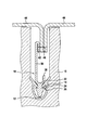
- FIG. 3 is a schematic view of a male clip according to a preferred embodiment of the present invention.
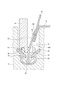
- FIG. 2 is a schematic view of the male clip of FIG. 1 coupled to a female clip for coupling a cushion body and a seat cover. 2 is an example of a process for assembling a connector comprising the male and female clips shown in FIG.
- FIG. 6 is a schematic view of a male clip according to another embodiment of the present invention.
- FIG. 5 is a first embodiment of a process for assembling a connector including the male clip and the female clip shown in FIG. 4.
- FIG. 5 is a second embodiment of a process for assembling a connector including the male clip and the female clip shown in FIG. 4.
- the male clip 10 includes a distal end portion 12 having a shape that facilitates insertion into the female clip 14.
- the male clip 10 protrudes gradually toward the distal end.
- the shape is provided.
- the male clip 10 has an arrowhead shape toward the tip.
- the male clip 10 is provided with a wing receiving portion, one of which has the reference numeral 16 in FIG.
- the wing receiving portion 16 is formed by a first wall 18 and a second wall 20 that are parallel to each other and parallel to the outer wall 22 and the inner wall 24 of the wing portion 26 of the female clip 14.
- the male clip 10 and the female clip 14 have a predetermined thickness in the direction orthogonal to the insertion direction ID and the width direction, that is, in the front and back direction with respect to the paper surface in FIG.
- the male clip 10 and the female clip 14 having the predetermined thickness do not necessarily have the same shape in the thickness direction.
- the plurality of male clips 10 and the female clips 14 are linearly formed so as to be easily bent. It may be connected by the connecting part.
- the connector includes a male clip 10 and a female clip 14 as shown in FIG.
- the first wall 18 of the male clip 10 engages with the back side of the wing portion 26 of the female clip 14 when the male clip 10 and the female clip 14 are engaged.
- the first wall 18 and the second wall 20 of the male clip 10 sandwich the wing portion 26 of the female clip 14 when engaged, thereby rotating the male clip 10 relative to the female clip 14. Restrict.
- the first wall 18 and the second wall 20 of the male clip 10 are at least partially in contact with the outer wall 22 and the inner wall 24 of the wing 26 of the female clip 14 in order to limit the rotation.
- the first wall 18 and the second wall 20 are formed in parallel to the outer wall 22 and the inner wall 24 of the wing portion 26. Further, the second wall 20 is formed longer than the first wall 18.
- the first wall 18 and the second wall 20 are inclined with respect to the insertion direction ID, similarly to the outer wall 22 and the inner wall 24.
- each angle ⁇ is 45 °. Further, the angle ⁇ is in the range of 10 ° to 80 °, and preferably in the range of 30 ° to 60 °.
- the insertion direction ID is the direction in which the male clip 10 is inserted into the female clip 14. Moreover, the broken line which shows insertion direction ID is shown by the width direction center position (left-right direction center position of a figure) of the male clip 10, as shown in FIG.1 and FIG.4, The width direction of the male clip 10 is shown. The center position line may be used.
- the male clip 10 has a direction changing portion 28 between the first wall 18 and the distal end portion 12, and the direction changing portion 28 extends from the first wall 18 toward the distal end, and is dimensioned in the width direction so as to approach each other.
- Decrease side walls 29, 31, and side walls 30, 32 extending from one end of the decrease side walls 29, 31 toward the tip and parallel to the insertion direction ID.
- One end side of the direction changing portion 28 is adjacent to the distal end portion 12, and the other end side of the direction changing portion 28 is adjacent to the first wall 18.
- Direction changing unit 28 has at least half the length L R of the distance L D between the first wall 18 of the male clip 10 as measured in the inserting direction ID and the second wall 20.
- the length L R of the direction changing section 28 a 5/8 of the distance L D between the first wall 18 and second wall 20.
- the direction changer 28 is useful in the assembly process detailed below.
- the male clip 10 includes a jig receiving part 34 formed by a first extension part 36 and a second extension part 38.
- the first extension 36 and the second extension 38 are extended from the second wall 20 toward the opposite side of the insertion method ID.
- the first extension 36 has a proximal portion 40 and a distal portion 39.
- the distal portion 39 is bendable. That is, it has a certain degree of flexibility.
- An example of each material is a thermoplastic elastomer (TPE).
- TPE thermoplastic elastomer
- the remaining portion of the male clip 10, including the proximal portion 40 of the first extension 36 can be less elastic, that is, a harder material, or more rigidly than the distal portion 39.
- linear polyethylene (LLDPE) is preferable.
- the proximal portion 40 and the distal portion 39 may be made integral with each other or connected by, for example, an adhesive. Further, the distal portion 39 may be formed with a width that is thin enough to be bent, or may be bent by at least one groove extending in the thickness direction. Moreover, you may use materials other than resin material, for example, soft materials, such as a nonwoven fabric.
- the free end 42 of the distal portion 39 is bent to be connected to the seat cover 44 by attachment means, for example a thread 46.
- Both the first extension part 36 and the second extension part 38 of the jig receiving part 34 are formed to protrude from the female clip 14 in the opposite direction to the insertion direction ID when engaged.
- the wing part 26 of the female clip 14 is received by the wing part receiving part 16 of the male clip 10 in the engaged state shown in FIG.
- the female clip 14 includes a U-shaped male clip receiving portion that can receive at least the distal end side of the male clip 10 relative to the first wall 18.
- a pair of wings 26 extending from the inner wall of the receiving portion are provided so as to reduce the opening size of the receiving portion.
- the wing portion 26 includes an inner wall 24 on the receiving portion side and an outer wall 22 on the opposite side on the outer side.
- the female clip 14 includes a second wing portion formed so as to extend outward from the U-shaped male clip from the opposite side of the wing portion 26. Since the second wing portion improves the contact area with the seat cushion 15, it is effective in improving the adhesion strength.
- the width dimension in the left-right direction of the side walls 30 and 32 of the direction changing portion 28 is equivalent to the gap between the left and right wing portions 26.
- the left and right side walls 30, 32 can come into contact with the tip portions of the left and right wing parts 26 in a state of entering the gap between the left and right wing parts 26.
- blade part 26 has a surface parallel with insertion direction ID, respectively. For this reason, when the male clip 10 is inserted into the female clip 14, the insertion posture of the male clip 10 is maintained by the tip portions of the left and right wing portions 26, so that the male clip 10 can be inserted into the female clip 14. Can be easily inserted.
- the seat cover 44 is attached to the free end 42 of the distal portion 39 by sewing (see thread 46).
- the male clip 10 is inserted into the female clip 14 using the jig 48.
- the jig 48 is inserted into the jig receiving portion 34 and then moved in the insertion direction ID, thereby inserting the male clip 10 into the female clip 14.
- the second extensions 38 are automatically received in the respective receiving portions 50 of the jig 48, thereby preventing the male clip 10 from rotating excessively during insertion.
- the second extension 38 protrudes more than the female clip 14 when viewed in the direction opposite to the insertion direction ID, like the first extension 36, thereby causing the second extension. This means that part 38 cannot be trapped under wing 26.
- the direction changer 28 serves to change the direction of the wing 26, if necessary, so that the male clip 10 is a female clip. Ensures that the wings 26 are correctly received in the wing receiving part 16 when inserted into the wing 14.
- the male clip 10 has the first wall 18 that engages with the back side of the wing portion 26 of the female clip 14 when engaged, Since the first wall 18 and the second wall 20 of the clip 10 sandwich the wing portion 26 when engaged, the rotation of the male clip 10 with respect to the female clip 14 can be restricted, and Insertion of the male clip 10 can be facilitated.
- FIGS. 1 to 3 a male clip and a connector according to another embodiment of the present invention will be described with reference to FIGS. It should be noted that the same or equivalent parts as those in the embodiment shown in FIGS. 1 to 3 are denoted by the same reference numerals, and the description thereof is omitted or simplified.
- the male clip 10B of the present embodiment includes two jig receiving portions 34 provided on both sides across the center line in the width direction of the male clip 10B.
- the two jig receiving parts 34 are formed by a first extension part 60 and a pair of second extension parts 38.
- the pair of second extensions 38 are formed symmetrically with the first extension 60 interposed therebetween. Both the first extension part 60 and the pair of second extension parts 38 are formed so as to protrude from the female clip 14 in the direction opposite to the insertion direction ID when engaged.
- the first extension portion 60 has a proximal portion 61 and a distal portion 62, and is provided along the center line in the width direction of the male clip 10B.
- the proximal portion 61 of the first extension portion 60 is embedded in the male clip 10B and is fixed to the male clip 10B.
- the distal portion 62 of the first extension 60 is provided so as to protrude from the second extension 38 in the direction opposite to the insertion direction ID. Further, the distal end of the proximal portion 61 of the first extension portion 60 may reach the direction changing portion 28.
- the 1st extension part 60 is formed with the material provided with a softness
- the 1st extension part 60 consists of a nonwoven fabric, for example, and has a softness
- TPE thermoplastic elastomer
- the seat cover 44 is attached to the free end 63 of the distal portion 62 by sewing (see thread 46).
- the male clip 10 B is inserted into the female clip 14 using the jig 48.
- the jig 48 is inserted into the jig receiving portion 34 and then moved in the insertion direction ID, thereby inserting the male clip 10B into the female clip 14.
- the jig 48 may be inserted into the jig receiving part 34 on one side in the width direction of the male clip 10B (see FIG.
- the second extension 38 is automatically received in the respective receiving portion 50 of the jig 48, thereby preventing the male clip 10B from excessively rotating during insertion.
- the second extension 38 protrudes more than the female clip 14 when viewed in the direction opposite to the insertion direction ID, as is the case with the first extension 60, and thereby the second extension. This means that part 38 cannot be trapped under wing 26.
- Other configurations and operational effects are the same as those of the embodiment shown in FIGS.
Landscapes
- Engineering & Computer Science (AREA)
- General Engineering & Computer Science (AREA)
- Mechanical Engineering (AREA)
- Aviation & Aerospace Engineering (AREA)
- Transportation (AREA)
- Manufacturing & Machinery (AREA)
- Connection Of Plates (AREA)
- Insertion Pins And Rivets (AREA)
Abstract
本発明は、雄型クリップと雌型クリップとを備える連結具に関しており、雄型クリップは、係合時に、雌型クリップの翼部の裏側に係合する第1壁を有する。雄型クリップは、第2壁を有し、第1壁及び第2壁は、係合時に、翼部を挟持し、雌型クリップに対する雄型クリップの回転を制限する。
Description
本発明は、雄型クリップと雌型クリップとからなる連結具に関連しており、前記雄型クリップは、係合時に、前記雌型クリップの翼部の裏側に係合する第1壁を備える。
「裏側に係合する」が意味するところは、係合のための当接中、当該第1壁が挿入方向に当該翼部を通過し、よって挿入方向で見て当該翼部の「裏側に」位置づけられた後における雄型クリップの第1壁と雌型クリップの翼部との連結又は係合である。
上述のような連結具は、例えば、特許文献1が知られている。本発明によれば、クリップは、側面から見て連続的又は個別分離的であってよい。それらはあらゆる適格な材料のものであってよい。好ましくは、雄型クリップは射出成形プラスチック部材であるのに対し、雌型クリップは金属又はホッグリングであるが、プラスチックであってもよい。
特許文献1に教示された構造では、雌型クリップに挿入する間、雄型クリップを適正な配向で安定して保持することが難しい。雄型クリップの不正確な挿入は、例えばシートクッションにおける発泡体といった別の要素への雌型クリップの取り付けを妨げることもある。
特許文献2は、クッション体とカバー体とを連結するための構造を開示している。その雄型クリップは第1壁及び第2壁を備える。前記第1壁及び第2壁の間の距離は、雌型クリップの翼部の厚さよりもかなり長い。雄型クリップと雌型クリップとからなる更なる連結具は、特許文献3、特許文献4、特許文献5及び特許文献6から知られる。
従って、本発明の目的は、雌型クリップへの雄型クリップの挿入が容易になるように、特許文献1の既知の連結具を改良することである。
本発明によれば、上記の目的は、雄型クリップが第2壁を有し、第1壁及び第2壁が係合時に翼部を挟持し、雌型クリップに対する雄型クリップの回転を制限するという特徴によって達成される。
言い換えると、雄型クリップは、雌型クリップの翼部によって、特にその第2壁によって安定して保持及び/又は案内され、結果として雌型クリップに対する雄型クリップのそれぞれの望ましくない回転の制限をもたらす。このことが確かであるのは、雌型クリップに挿入される間、雄型クリップを安定して指向させられないことの主たる理由は、雄型クリップを挿入するための力が正確に挿入方向ではなく、ある角度を伴って加えられた場合に、雄型クリップは雌型クリップに対して回転しがちであるからである。
本発明によれば、挟持による回転防止の程度は極めて高くなり得る。詳しくは、回転は前記挟持によって完全に防ぎ得る。
本発明によれば、雄型クリップの第1壁及び第2壁は、好ましくは、回転を制限するために少なくとも部分的に接触する雌型クリップの翼部の壁に対して平行である。
言い換えると、全体構造は、回転制限のために互いに接触し合う平行な壁を含み、結果として高信頼システムをもたらす。
雄型クリップの第1壁及び第2壁が雄型クリップの雌型クリップへの挿入方向に平行であってはならないことは明らかである。しかしそれらは垂直であってもならない。そうではなく、雄型クリップの第1壁及び第2壁の少なくとも一方と挿入方向との間の角度は、10°~80°の範囲であり、好ましくは、30°~60°の範囲である。
そのような構造により、挟持が回転を確実に制限する一方、雌型クリップへの雄型クリップの挿入を妨げないことが保証される。
好ましくは、雄型クリップの第2壁は、第1壁よりも長い。
この構造は、挿入を容易にするのと同時に、回転を効果的に制限又は防止するのを助ける。
本発明の更なる好ましい実施形態によれば、雄型クリップの先端部は、突出した形状又は矢じり形状を有する。これらは極めて単純な構造で、製造が容易である。
好ましい実施形態によれば、雄型クリップは、第1壁と先端部との間に方向変更部を有し、方向変更部は、挿入方向に対して平行な少なくとも1つの側壁を有する。
方向変更部は、翼部が過度に回転したために挿入がまっすぐにならないように雌型クリップが動くことなく雄型クリップを雌型クリップに進入させるために、必要に応じて、雌型クリップの翼部を方向変更するのに役立つ。
方向変更部は、好ましくは、先端部と隣接している。このため、方向変更は先端部が雌型クリップの翼部の内端の間に通過した直後に行われ得る。
この結果、方向変更は先端部の挿入直後に始まることになる。
好ましくは、方向変更部は、挿入方向において測定した雄型クリップの第1壁と第2壁との間の距離の少なくとも半分の長さを有する。
この構成により、必要な場合に、十分な方向変更動作が生じることが保証される。
雄型クリップがジグ受け部を有することがさらに好ましい。
雄型クリップを雌型クリップに挿入するためのジグの使用は、いくつかの利点を有する。1つは、雄型クリップが適正な挿入指向から外れて動くのを防ぐためにそうしたジグを使用できるということである。別の利点は、クリップが到達するのが難しい場合に、ジグの助けによって雄型クリップを雌型クリップに挿入できるということである。
好ましくは、ジグ受け部は、係合時に、挿入方向と反対方向に雌型クリップよりも両方とも突出する第1延長部及び第2延長部により形成される。言い換えると、第1延長部及び第2延長部は、雄型クリップが雌型クリップと係合した時に、挿入方向と反対方向に雌型クリップよりも上方に突出する。
これにより、ジグが雄型クリップのジグ受け部に進入するように方向づけられ、それにより雄型クリップが雌型クリップに押し込まれる時に、ジグは雌型クリップに到達しない。このように、雄型クリップを挿入しようとする間に雌型クリップを誤った方向に向ける危険は、防止されないとしても、少なくとも低減する。
本発明の好ましい実施形態によれば、第1延長部は、近位部と遠位部を有し、遠位部は折り曲げ可能である。
遠位部が折り曲げられることにより、例えばシートカバーといった連結すべき物に雄型クリップを連結することはより容易になる。近位部は、クリップ動作及び連結といった必要な機能を保証するためにより大きい剛性を有する。
近位部と遠位部は好ましくは互いに一体である。例えば、各部は、溶融状態で結合した時に他方に付着する異なるエラストマーで作られる。あるいは、接着剤を用いた接合を使用してそれらを一体に結合するのを保証できる。最後に、両部を一緒に押し出すこともできる。
雄型クリップは、雄型クリップの幅方向中心線を挟んで両側に設けられる2つのジグ受け部を有する。
2つのジグ受け部は、雄型クリップの幅方向中心線に沿って設けられる第1延長部及び第1延長部を挟んで対称に形成される一対の第2延長部によって形成され、第1延長部及び一対の第2延長部は、係合時に、雄型クリップの雌型クリップへの挿入方向と反対方向に雌型クリップよりも両方とも突出する。
好ましくは、第1延長部は、不織布からなる。
第1延長部は、近位部と遠位部を有し、近位部は、雄型クリップに埋設されている。
本発明は、上に詳述したような連結具を提供するだけでなく、その雄型クリップもまた別に提供する。
さらに、本発明は、シートカバーをクッションに取り付けるための上述した雄型クリップを備えるシートカバー、及び、上述した連結具を備えるシートを提供する。
以下において、更なる詳細を備えた添付図面を参照しつつ、好ましい例示的実施形態を用いて本発明を詳細に説明する。
図1に示すように、雄型クリップ10は、雌型クリップ14への挿入を容易にする形状の先端部12を備え、本実施形態では、先端に向けて漸次幅寸法が小さくなるような突出した形状を備える。その結果、雄型クリップ10は先端に向かう矢じり形状を有する。シートクッション15に埋め込まれた雌型クリップ14との係合のために、雄型クリップ10は翼部受け部を備えており、その1つが図1において参照番号16を有している。翼部受け部16は、互いに平行であり、且つ雌型クリップ14の翼部26の外壁22及び内壁24と平行である第1壁18及び第2壁20によって形成される。
また、この雄型クリップ10及び雌型クリップ14は、挿入方向ID及び幅方向に直交する方向、すなわち、図2における紙面に対して表裏方向に所定の厚みを有する。この所定の厚みを有する雄型クリップ10及び雌型クリップ14は、必ずしも厚み方向に同じ形状である必要はなく、例えば、互いに曲げやすいように複数の雄型クリップ10と雌型クリップ14を線状の連結部によって連結させたものであってもよい。
また、この雄型クリップ10及び雌型クリップ14は、挿入方向ID及び幅方向に直交する方向、すなわち、図2における紙面に対して表裏方向に所定の厚みを有する。この所定の厚みを有する雄型クリップ10及び雌型クリップ14は、必ずしも厚み方向に同じ形状である必要はなく、例えば、互いに曲げやすいように複数の雄型クリップ10と雌型クリップ14を線状の連結部によって連結させたものであってもよい。
連結具は、図2に示すように、雄型クリップ10と雌型クリップ14とを備える。雄型クリップ10の第1壁18は、雄型クリップ10と雌型クリップ14との係合時に、雌型クリップ14の翼部26の裏側に係合する。そして、雄型クリップ10の第1壁18及び第2壁20は、係合時に、雌型クリップ14の翼部26を挟持して、これにより、雌型クリップ14に対する雄型クリップ10の回転を制限する。
雄型クリップ10の第1壁18及び第2壁20は、上記回転を制限するために、雌型クリップ14の翼部26の外壁22及び内壁24と少なくとも部分的に接触する。また、第1壁18及び第2壁20は、翼部26の外壁22及び内壁24に対して平行に形成されている。また、第2壁20は、第1壁18よりも長く形成されている。また、第1壁18及び第2壁20は、外壁22及び内壁24と同様に、挿入方向IDに対して傾斜している。本実施形態では、それぞれの角度αは45°である。また、角度αは、10°~80°の範囲であり、好ましくは、30°~60°の範囲である。なお、挿入方向IDは、雄型クリップ10の雌型クリップ14への挿入方向である。また、挿入方向IDを示す破線は、図1及び図4に示すように、雄型クリップ10の幅方向中心位置(図の左右方向中心位置)に示されており、雄型クリップ10の幅方向中心位置線としてしてもよい。
雄型クリップ10は、第1壁18と先端部12との間に方向変更部28を有し、方向変更部28は、第1壁18から先端に向けて延び、互いに近づくように幅方向寸法が減少する減少側壁29、31と、減少側壁29、31の一端から先端に向けて延び、挿入方向IDに対して互いに平行な側壁30、32と、を有する。方向変更部28の一端側は、先端部12と隣接し、方向変更部28の他端側は、第1壁18と隣接している。
方向変更部28は、挿入方向IDにおいて測定した雄型クリップ10の第1壁18と第2壁20との間の距離LDの少なくとも半分の長さLRを有する。そして、本実施形態では、方向変更部28の長さLRは、第1壁18と第2壁20との間の距離LDの5/8である。方向変更部28は、以下で詳述する組み立てプロセスにおいて有益である。
雄型クリップ10は、第1延長部36及び第2延長部38によって形成されるジグ受け部34を備える。第1延長部36と第2延長部38は、第2壁20から挿入方IDの反対側に向けて延設されている。第1延長部36は、近位部40と遠位部39を有する。遠位部39は折り曲げ可能である。すなわち、ある程度の柔軟性を有する。それぞれの材料の実施例は熱可塑性エラストマー(TPE)である。これに対して、第1延長部36の近位部40を含む雄型クリップ10の残りの部分は、より弾性のない、つまりもっと硬い材料、さらに言うと、遠位部39よりも硬いことが好ましく、例えばリニアポリエチレン(LLDPE)である。近位部40と遠位部39は、互いに一体に作るか、又は例えば接着剤によって接続してもよい。また、遠位部39を折り曲げ可能な程に薄い幅寸法で形成するか、厚さ方向に対して延設された少なくとも1つ以上の溝状によって折り曲げることを可能にさせてもよい。また、樹脂材料以外の材料、例えば、不織布などの柔らかい材料を使用してもよい。
遠位部39の自由端42は、取り付け手段、例えば糸46によってシートカバー44に結合されるために折り曲げられている。
ジグ受け部34の第1延長部36及び第2延長部38の両方は、係合時において、挿入方向IDと反対方向に雌型クリップ14よりも突出するように形成されている。
図2に示した係合状態において、雌型クリップ14の翼部26は雄型クリップ10の翼部受け部16に受け入れられる。具体的には、雌型クリップ14は、雄型クリップ10の少なくとも第1壁18よりも先端側を受容可能なU字状の雄型クリップ受容部を備える。雄型クリップ受容部の開口部両端には、受容部の開口寸法を小さくするように受容部の内側壁から延出する一対の翼部26を備える。翼部26は、受容部側にある内壁24と、その反対側で外側にある外壁22と、を備える。翼部受け部16に翼部26が受け入れられた時に、翼部26の内壁24は、雄型クリップ10の第1壁18と対向して配置され、翼部26の外壁22は、雄型クリップ10の第2壁20に対向して配置される。また、雌型クリップ14は、翼部26の反対側からU字状の雄型クリップよりも外側に延出するように形成された第2の翼部を備える。この第2の翼部は、シートクッション15との接触面積を向上させるので、密着強度の向上に有効である。
また、方向変更部28の側壁30、32の左右方向の幅寸法は、左右の翼部26間の隙間と同等である。雄型クリップ10を雌型クリップ14に挿入させるとき、左右の側壁30、32は、左右の翼部26間の隙間に進入した状態で、左右の翼部26の先端部と接触可能である。また、左右の翼部26の先端部は、挿入方向IDに対して平行な面をそれぞれ有する。このため、雄型クリップ10を雌型クリップ14に挿入させるときに、左右の翼部26の先端部により雄型クリップ10の挿入姿勢が保持されるので、雄型クリップ10の雌型クリップ14への挿入を容易にすることができる。
上述の連結具の組み立てについて、図3を参照して以下に説明する。第1ステップにおいて、シートカバー44が縫製(糸46参照)によって遠位部39の自由端42に取り付けられる。次のステップでは、ジグ48を使って雄型クリップ10が雌型クリップ14に挿入される。このために、ジグ48はジグ受け部34に挿入されてから、挿入方向IDに動かされ、これによって雄型クリップ10を雌型クリップ14に挿入する。ジグ48をジグ受け部34に入れる時に、第2延長部38が自動的にジグ48のそれぞれの受け部50に受け入れられるので、挿入の間、雄型クリップ10が過度に回転するのを防ぐ。これに関して留意すべきことは、特に第2延長部38が、第1延長部36と同様に挿入方向IDと反対方向で見た場合、雌型クリップ14よりも突出しており、これによって第2延長部38は翼部26の下に捕捉され得ないということである。
ジグ48を用いた雌型クリップ14への雄型クリップ10の上記挿入の間、方向変更部28は、必要な場合、翼部26を方向変更する働きをし、雄型クリップ10が雌型クリップ14に挿入される時に翼部26が翼部受け部16に正しく受け入れられるのを保証する。
以上説明したように、本実施形態の連結具によれば、雄型クリップ10が、係合時に、雌型クリップ14の翼部26の裏側に係合する第1壁18を有し、雄型クリップ10の第1壁18及び第2壁20が、係合時に、翼部26を挟持するため、雌型クリップ14に対する雄型クリップ10の回転を制限することができ、雌型クリップ14への雄型クリップ10の挿入を容易にすることができる。
次に、図4~図6を参照して、本発明の別の実施形態に従った雄型クリップ及び連結具について説明する。なお、なお、上記図1~図3に示す実施形態と同一又は同等部分については、図面に同一符号を付してその説明を省略或いは簡略化する。
本実施形態の雄型クリップ10Bは、図4に示すように、雄型クリップ10Bの幅方向中心線を挟んで両側に設けられる2つのジグ受け部34を備える。2つのジグ受け部34は、第1延長部60及び一対の第2延長部38によって形成される。一対の第2延長部38は、第1延長部60を挟んで対称に形成されている。第1延長部60及び一対の第2延長部38の両方は、係合時において、挿入方向IDと反対方向に雌型クリップ14よりも突出するように形成されている。
第1延長部60は、近位部61と遠位部62を有し、雄型クリップ10Bの幅方向中心線に沿って設けられている。第1延長部60の近位部61は、雄型クリップ10Bに埋設され、雄型クリップ10Bに固着されている。第1延長部60の遠位部62は、挿入方向IDと反対方向に第2延長部38よりも突出するように設けられている。また、第1延長部60の近位部61の先端は、方向変更部28まで達していてもよい。そして、第1延長部60は、柔軟性を備える材料で形成されていることが好ましい。具体的には、第1延長部60は、例えば、不織布からなり、柔軟性を有する。また、不織布の繊維の材質に特に制限はない。なお、もし第1延長部60が雄型クリップ10の残りの部分より柔らかい材料であった場合(例えば熱可塑性エラストマー(TPE))、第1延長部60は、ジグ受け部34の底部から延びるような形態、すなわち第1延長部60の近位部61が存在しない形状であってもよい。
本実施形態の雄型クリップ10Bを使用した連結具の組み立てについて、図5及び図6を参照して以下に説明する。第1ステップにおいて、シートカバー44が縫製(糸46参照)によって遠位部62の自由端63に取り付けられる。次のステップでは、ジグ48を使って雄型クリップ10Bが雌型クリップ14に挿入される。このために、ジグ48はジグ受け部34に挿入されてから、挿入方向IDに動かされ、これによって雄型クリップ10Bを雌型クリップ14に挿入する。この時、ジグ48は、雄型クリップ10Bの幅方向一方側のジグ受け部34に挿入されてもよいし(図5参照)、幅方向他方側のジグ受け部34に挿入されてもよい(図6参照)。ジグ48をジグ受け部34に入れる時に、第2延長部38が自動的にジグ48のそれぞれの受け部50に受け入れられるので、挿入の間、雄型クリップ10Bが過度に回転するのを防ぐ。これに関して留意すべきことは、特に第2延長部38が、第1延長部60と同様に挿入方向IDと反対方向で見た場合、雌型クリップ14よりも突出しており、これによって第2延長部38は翼部26の下に捕捉され得ないということである。
その他の構成及び作用効果については、上記図1~図3に示す実施形態と同様である。
その他の構成及び作用効果については、上記図1~図3に示す実施形態と同様である。
上記の説明、クレーム及び図面において開示された本発明の特徴は、それら自体によっても任意の組合せによっても本発明の種々の実施形態の実現にとって有用となり得る。
本出願は、2017年4月7日出願のドイツ連邦共和国特許出願(102017003420.6)に基づくものであり、その内容はここに参照として取り込まれる。
10,10B 雄型クリップ
12 先端部
14 雌型クリップ
15 シートクッション
16 翼部受け部
18 第1壁
20 第2壁
22 外壁(壁)
24 内壁(壁)
26 翼部
28 方向変更部
29、31 減少側壁
30、32 側壁
34 ジグ受け部
36,60 第1延長部
38 第2延長部
39,62 遠位部
40,61 近位部
42,63 自由端
44 シートカバー
46 糸
48 ジグ
50 受け部
ID 挿入方向
LR 方向変更部の長さ
LD 第1壁と第2壁との間の距離
12 先端部
14 雌型クリップ
15 シートクッション
16 翼部受け部
18 第1壁
20 第2壁
22 外壁(壁)
24 内壁(壁)
26 翼部
28 方向変更部
29、31 減少側壁
30、32 側壁
34 ジグ受け部
36,60 第1延長部
38 第2延長部
39,62 遠位部
40,61 近位部
42,63 自由端
44 シートカバー
46 糸
48 ジグ
50 受け部
ID 挿入方向
LR 方向変更部の長さ
LD 第1壁と第2壁との間の距離
Claims (19)
- 雄型クリップ(10,10B)と雌型クリップ(14)とを備え、
前記雄型クリップ(10,10B)は、係合時に、前記雌型クリップ(14)の翼部(26)の裏側に係合する第1壁(18)を有し、
前記雄型クリップ(10,10B)は、第2壁(20)を有し、
前記第1壁(18)及び前記第2壁(20)は、係合時に、前記翼部(26)を挟持し、前記雌型クリップ(14)に対する前記雄型クリップ(10,10B)の回転を制限することを特徴とする連結具。 - 前記雄型クリップ(10,10B)の前記第1壁(18)及び前記第2壁(20)は、前記回転を制限するために少なくとも部分的に接触する前記雌型クリップ(14)の前記翼部(26)の壁(22、24)に対して平行であることを特徴とする請求項1に記載の連結具。
- 前記雄型クリップ(10,10B)の前記第1壁(18)及び前記第2壁(20)の少なくとも一方と前記雄型クリップの前記雌型クリップへの挿入方向(ID)との間の角度(α)は、10°~80°の範囲であり、好ましくは、30°~60°の範囲であることを特徴とする請求項1又は2に記載の連結具。
- 前記雄型クリップ(10,10B)の前記第2壁(20)は、前記第1壁(18)よりも長いことを特徴とする請求項1~3のいずれか1項に記載の連結具。
- 前記雄型クリップ(10,10B)の先端部(12)は、突出した形状又は矢じり形状を有することを特徴とする請求項1~4のいずれか1項に記載の連結具。
- 前記雄型クリップ(10,10B)は、前記第1壁(18)と前記先端部(12)との間に方向変更部(28)を有し、
前記方向変更部(28)は、前記雄型クリップの前記雌型クリップへの挿入方向(ID)に対して平行な少なくとも1つの側壁(30、32)を有することを特徴とする請求項5に記載の連結具。 - 前記方向変更部(28)は、前記先端部(12)と隣接することを特徴とする請求項6に記載の連結具。
- 前記方向変更部(28)は、前記挿入方向(ID)において測定した前記雄型クリップ(10)の前記第1壁(18)と前記第2壁(20)との間の距離(LD)の少なくとも半分の長さ(LR)を有することを特徴とする請求項6又は7に記載の連結具。
- 前記雄型クリップ(10)は、ジグ受け部(34)を有することを特徴とする請求項1~8のいずれか1項に記載の連結具。
- 前記ジグ受け部(34)は、係合時に、前記雄型クリップの前記雌型クリップへの挿入方向(ID)と反対方向に前記雌型クリップ(14)よりも両方とも突出する第1延長部(36)及び第2延長部(38)により形成されることを特徴とする請求項9に記載の連結具。
- 前記第1延長部(36)は、近位部(40)と遠位部(39)を有し、
前記遠位部(39)は、折り曲げ可能であることを特徴とする請求項10に記載の連結具。 - 前記近位部(40)と前記遠位部(39)は、互いに一体であることを特徴とする請求項11に記載の連結具。
- 前記雄型クリップ(10B)は、前記雄型クリップ(10B)の幅方向中心線を挟んで両側に設けられる2つのジグ受け部(34)を有することを特徴とする請求項1~8のいずれか1項に記載の連結具。
- 前記2つのジグ受け部(34)は、前記雄型クリップ(10B)の幅方向中心線に沿って設けられる第1延長部(60)及び前記第1延長部(60)を挟んで対称に形成される一対の第2延長部(38)によって形成され、
前記第1延長部(60)及び前記一対の第2延長部(38)は、係合時に、前記雄型クリップの前記雌型クリップへの挿入方向(ID)と反対方向に前記雌型クリップ(14)よりも両方とも突出することを特徴とする請求項13に記載の連結具。 - 前記第1延長部(60)は、不織布からなることを特徴とする請求項14に記載の連結具。
- 前記第1延長部(60)は、近位部(61)と遠位部(62)を有し、
前記近位部(61)は、雄型クリップ(10B)に埋設されていることを特徴とする請求項15に記載の連結具。 - 請求項1~16のいずれか1項に記載の連結具用の雄型クリップ(10)。
- 請求項1~16のいずれか1項に記載の連結具の雄型クリップ(10)を備えるシートカバー(44)。
- シートカバー(44)をクッション(15)に取り付けるための請求項1~16のいずれか1項に記載の連結具(10、14)を備えるシート。
Priority Applications (1)
| Application Number | Priority Date | Filing Date | Title |
|---|---|---|---|
| DE112018001913.6T DE112018001913B4 (de) | 2017-04-07 | 2018-03-27 | Verbindungsvorrichtung, Clippatrize, Sitzbezug und Sitz |
Applications Claiming Priority (2)
| Application Number | Priority Date | Filing Date | Title |
|---|---|---|---|
| DE102017003420.6A DE102017003420A1 (de) | 2017-04-07 | 2017-04-07 | Verbindungsvorrichtung, clippatrize für eine solche verbindungs- vorrichtung, sitzbezug mit einer clippatrize einer solchen verbindungsvorrichtung und sitz mit einer solchen verbindungsvorrichtung |
| DE102017003420.6 | 2017-04-07 |
Publications (1)
| Publication Number | Publication Date |
|---|---|
| WO2018186245A1 true WO2018186245A1 (ja) | 2018-10-11 |
Family
ID=63587968
Family Applications (1)
| Application Number | Title | Priority Date | Filing Date |
|---|---|---|---|
| PCT/JP2018/012611 Ceased WO2018186245A1 (ja) | 2017-04-07 | 2018-03-27 | 連結具、雄型クリップ、シートカバー、及びシート |
Country Status (2)
| Country | Link |
|---|---|
| DE (2) | DE102017003420A1 (ja) |
| WO (1) | WO2018186245A1 (ja) |
Cited By (4)
| Publication number | Priority date | Publication date | Assignee | Title |
|---|---|---|---|---|
| US20230331126A1 (en) * | 2020-03-06 | 2023-10-19 | Ts Tech Co., Ltd. | Seat and assembling method therefor |
| JP2024035400A (ja) * | 2022-09-02 | 2024-03-14 | Ykk株式会社 | クリップ、表皮材取付具およびクリップ連結体 |
| WO2024118287A1 (en) * | 2022-11-30 | 2024-06-06 | Ykk Corporation Of America | Retainer for attaching a covering material to a structure |
| KR20250085792A (ko) | 2022-10-18 | 2025-06-12 | 와이케이케이 가부시끼가이샤 | 클립 및 클립 연결체 |
Families Citing this family (3)
| Publication number | Priority date | Publication date | Assignee | Title |
|---|---|---|---|---|
| DE112015006485B4 (de) * | 2015-04-24 | 2026-02-05 | Ykk Corporation | Clipbuchse, Schaumformkörper und Herstellungsverfahren für einen Schaumformkörper |
| DE102017003420A1 (de) | 2017-04-07 | 2018-10-11 | Ykk Corporation | Verbindungsvorrichtung, clippatrize für eine solche verbindungs- vorrichtung, sitzbezug mit einer clippatrize einer solchen verbindungsvorrichtung und sitz mit einer solchen verbindungsvorrichtung |
| DE102019133589A1 (de) * | 2019-12-09 | 2021-06-10 | Elkamet Kunststofftechnik Gmbh | Verbindungsanordnung |
Citations (3)
| Publication number | Priority date | Publication date | Assignee | Title |
|---|---|---|---|---|
| JP2002021823A (ja) * | 2000-07-04 | 2002-01-23 | Nifco Inc | 板材の取付構造 |
| WO2013069114A1 (ja) * | 2011-11-09 | 2013-05-16 | Ykk株式会社 | 表皮材止着用コード |
| JP2016106979A (ja) * | 2014-12-10 | 2016-06-20 | Ykk株式会社 | 表皮材止着用クリップ |
Family Cites Families (12)
| Publication number | Priority date | Publication date | Assignee | Title |
|---|---|---|---|---|
| US5733001A (en) | 1996-11-19 | 1998-03-31 | Roberts; Clifford D. | Seat cover retainer apparatus and method of using same |
| US5762397A (en) | 1997-03-24 | 1998-06-09 | Venuto; Dennis | Wire attachment to a seat frame |
| DE19952059A1 (de) | 1999-10-28 | 2001-05-03 | Seibel Plastiko Ag | Befestigungselement zum Verbinden eines Polsterbezuges an einem Sitz |
| EP1186468B1 (de) | 2000-09-06 | 2005-01-05 | Benteler Ag | Polsterung für die Rückenlehne eines Kraftfahrzeugsitzes |
| DE102004040400A1 (de) | 2003-08-20 | 2005-04-21 | Woobridge Foam Corp Mississaug | Deckenbefestigungsvorrichtung |
| DE102006020306A1 (de) | 2006-05-03 | 2007-11-08 | Andreas Erler | Befestigungsvorrichtung zum Verbinden eines Polsterbezuges mit einem Polster |
| JP4908315B2 (ja) | 2006-07-13 | 2012-04-04 | 矢崎総業株式会社 | 取付構造 |
| WO2008050393A1 (fr) | 2006-10-24 | 2008-05-02 | Ykk Corporation | Structure pour connecter un corps de coussinet et un corps de couvercle |
| JP2009148407A (ja) | 2007-12-20 | 2009-07-09 | Toyota Boshoku Corp | 表皮材の吊込み構造 |
| US9743777B2 (en) | 2013-11-11 | 2017-08-29 | Ykk Corporation | Drawn instrument for securely attaching a cover |
| DE112015006485B4 (de) | 2015-04-24 | 2026-02-05 | Ykk Corporation | Clipbuchse, Schaumformkörper und Herstellungsverfahren für einen Schaumformkörper |
| DE102017003420A1 (de) | 2017-04-07 | 2018-10-11 | Ykk Corporation | Verbindungsvorrichtung, clippatrize für eine solche verbindungs- vorrichtung, sitzbezug mit einer clippatrize einer solchen verbindungsvorrichtung und sitz mit einer solchen verbindungsvorrichtung |
-
2017
- 2017-04-07 DE DE102017003420.6A patent/DE102017003420A1/de not_active Withdrawn
-
2018
- 2018-03-27 DE DE112018001913.6T patent/DE112018001913B4/de active Active
- 2018-03-27 WO PCT/JP2018/012611 patent/WO2018186245A1/ja not_active Ceased
Patent Citations (3)
| Publication number | Priority date | Publication date | Assignee | Title |
|---|---|---|---|---|
| JP2002021823A (ja) * | 2000-07-04 | 2002-01-23 | Nifco Inc | 板材の取付構造 |
| WO2013069114A1 (ja) * | 2011-11-09 | 2013-05-16 | Ykk株式会社 | 表皮材止着用コード |
| JP2016106979A (ja) * | 2014-12-10 | 2016-06-20 | Ykk株式会社 | 表皮材止着用クリップ |
Cited By (7)
| Publication number | Priority date | Publication date | Assignee | Title |
|---|---|---|---|---|
| US20230331126A1 (en) * | 2020-03-06 | 2023-10-19 | Ts Tech Co., Ltd. | Seat and assembling method therefor |
| US12109926B2 (en) * | 2020-03-06 | 2024-10-08 | Ts Tech Co., Ltd. | Seat and assembling method therefor |
| US20250001920A1 (en) * | 2020-03-06 | 2025-01-02 | Ts Tech Co., Ltd. | Seat and assembling method therefor |
| JP2024035400A (ja) * | 2022-09-02 | 2024-03-14 | Ykk株式会社 | クリップ、表皮材取付具およびクリップ連結体 |
| KR20250085792A (ko) | 2022-10-18 | 2025-06-12 | 와이케이케이 가부시끼가이샤 | 클립 및 클립 연결체 |
| WO2024118287A1 (en) * | 2022-11-30 | 2024-06-06 | Ykk Corporation Of America | Retainer for attaching a covering material to a structure |
| JP2025531142A (ja) * | 2022-11-30 | 2025-09-19 | Ykk株式会社 | 被覆材料を構造体に取り付けるための保持具 |
Also Published As
| Publication number | Publication date |
|---|---|
| DE112018001913T5 (de) | 2019-12-19 |
| DE102017003420A1 (de) | 2018-10-11 |
| DE112018001913B4 (de) | 2023-09-28 |
Similar Documents
| Publication | Publication Date | Title |
|---|---|---|
| JP5118066B2 (ja) | パネルの穴に押し込むスナップ式の係合部を備える締結具 | |
| TWI388306B (zh) | Cleaning tool | |
| KR100763864B1 (ko) | 클리닝 와이퍼의 유지 장치 및 유지 장치를 사용하는클리닝 물품 | |
| CN103917136B (zh) | 表皮材料固定用线 | |
| KR20160037200A (ko) | 클립 및 코드 | |
| US10471247B2 (en) | Catheter coupling | |
| JP6389510B2 (ja) | 止血器具 | |
| US12106874B2 (en) | Wiring member | |
| KR101559920B1 (ko) | 카데터 고정밴드 | |
| JP6250982B2 (ja) | コネクタ接続用ロック部材 | |
| JP2015014339A (ja) | 長尺体カバーの接続構造 | |
| JP5669253B2 (ja) | 合成樹脂製スナップ | |
| JP4865576B2 (ja) | 螺旋状ケーブル支持具の連結具 | |
| JP2020133642A (ja) | クイックファスナ | |
| JP2020110223A (ja) | 気管切開チューブ用の固定具 | |
| JP4152483B2 (ja) | 車両用サンバイザ | |
| KR200498150Y1 (ko) | 탄성체를 이용한 인트라오럴 센서 홀더 | |
| JP2011245203A5 (ja) | ||
| CN217682758U (zh) | 一种用于管道连接处的防拆线扣 | |
| JPS6041899Y2 (ja) | ホ−ス接続装置 | |
| JP2014143774A (ja) | ワイヤハーネス用プロテクタ及びワイヤハーネス | |
| JP3147141U (ja) | シート状部材の綴じ合せ具およびこれを用いた綴じ合せ構造 | |
| KR200400908Y1 (ko) | 미니 스프링클러용 관연결구 | |
| JPH03265792A (ja) | 管継手 | |
| JP2017001706A (ja) | 医科用結束バンド |
Legal Events
| Date | Code | Title | Description |
|---|---|---|---|
| 121 | Ep: the epo has been informed by wipo that ep was designated in this application |
Ref document number: 18780479 Country of ref document: EP Kind code of ref document: A1 |
|
| 122 | Ep: pct application non-entry in european phase |
Ref document number: 18780479 Country of ref document: EP Kind code of ref document: A1 |
|
| NENP | Non-entry into the national phase |
Ref country code: JP |