WO2018181554A1 - 着色アルミニウム板 - Google Patents
着色アルミニウム板 Download PDFInfo
- Publication number
- WO2018181554A1 WO2018181554A1 PCT/JP2018/012936 JP2018012936W WO2018181554A1 WO 2018181554 A1 WO2018181554 A1 WO 2018181554A1 JP 2018012936 W JP2018012936 W JP 2018012936W WO 2018181554 A1 WO2018181554 A1 WO 2018181554A1
- Authority
- WO
- WIPO (PCT)
- Prior art keywords
- resin layer
- aluminum plate
- aluminum
- plate according
- colored
- Prior art date
- Legal status (The legal status is an assumption and is not a legal conclusion. Google has not performed a legal analysis and makes no representation as to the accuracy of the status listed.)
- Ceased
Links
Images




Classifications
-
- B—PERFORMING OPERATIONS; TRANSPORTING
- B05—SPRAYING OR ATOMISING IN GENERAL; APPLYING FLUENT MATERIALS TO SURFACES, IN GENERAL
- B05D—PROCESSES FOR APPLYING FLUENT MATERIALS TO SURFACES, IN GENERAL
- B05D7/00—Processes, other than flocking, specially adapted for applying liquids or other fluent materials to particular surfaces or for applying particular liquids or other fluent materials
- B05D7/14—Processes, other than flocking, specially adapted for applying liquids or other fluent materials to particular surfaces or for applying particular liquids or other fluent materials to metal, e.g. car bodies
-
- B—PERFORMING OPERATIONS; TRANSPORTING
- B32—LAYERED PRODUCTS
- B32B—LAYERED PRODUCTS, i.e. PRODUCTS BUILT-UP OF STRATA OF FLAT OR NON-FLAT, e.g. CELLULAR OR HONEYCOMB, FORM
- B32B15/00—Layered products comprising a layer of metal
- B32B15/04—Layered products comprising a layer of metal comprising metal as the main or only constituent of a layer, which is next to another layer of the same or of a different material
- B32B15/08—Layered products comprising a layer of metal comprising metal as the main or only constituent of a layer, which is next to another layer of the same or of a different material of synthetic resin
-
- C—CHEMISTRY; METALLURGY
- C23—COATING METALLIC MATERIAL; COATING MATERIAL WITH METALLIC MATERIAL; CHEMICAL SURFACE TREATMENT; DIFFUSION TREATMENT OF METALLIC MATERIAL; COATING BY VACUUM EVAPORATION, BY SPUTTERING, BY ION IMPLANTATION OR BY CHEMICAL VAPOUR DEPOSITION, IN GENERAL; INHIBITING CORROSION OF METALLIC MATERIAL OR INCRUSTATION IN GENERAL
- C23C—COATING METALLIC MATERIAL; COATING MATERIAL WITH METALLIC MATERIAL; SURFACE TREATMENT OF METALLIC MATERIAL BY DIFFUSION INTO THE SURFACE, BY CHEMICAL CONVERSION OR SUBSTITUTION; COATING BY VACUUM EVAPORATION, BY SPUTTERING, BY ION IMPLANTATION OR BY CHEMICAL VAPOUR DEPOSITION, IN GENERAL
- C23C26/00—Coating not provided for in groups C23C2/00 - C23C24/00
-
- C—CHEMISTRY; METALLURGY
- C25—ELECTROLYTIC OR ELECTROPHORETIC PROCESSES; APPARATUS THEREFOR
- C25F—PROCESSES FOR THE ELECTROLYTIC REMOVAL OF MATERIALS FROM OBJECTS; APPARATUS THEREFOR
- C25F3/00—Electrolytic etching or polishing
- C25F3/02—Etching
- C25F3/04—Etching of light metals
Definitions
- the present invention relates to a colored aluminum plate.
- Aluminum plates used for aluminum products or aluminum alloy products are colored to enhance surface protection and appearance.
- Patent Document 1 discloses that “(i) a substrate made of aluminum or an aluminum alloy is anodized in a treatment solution containing phosphoric acid to form a plurality of pores on the surface of the substrate.
- Forming a anodic oxide film comprising: (ii) treating the substrate with warm water at 40 to 100 ° C .; and (iii) forming the substrate into a pigment composition for coloring containing pigment particles, a dispersant and water.
- a method for producing a colored aluminum product or a colored aluminum alloy product comprising: a step of immersing and filling pigment particles into a plurality of pores of an anodized film on a substrate surface and coloring the pigment particles.
- a colored aluminum product or colored aluminum alloy product colored in any one of black, red, blue, yellow, green and white ([Claim 11] to [Claim 11]). Claim 16]).
- the inventors of the present invention have studied the manufacturing method described in Patent Document 1, and as a result, the manufactured colored aluminum product or the colored aluminum alloy product has a glossiness that is too high and has a high-quality metallic appearance, that is, gloss. It has been clarified that it is difficult to say that it has an appearance with a metallic texture that disappears.
- an object of the present invention is to provide a colored aluminum plate having an appropriate glossiness.
- the present inventors have provided a resin layer containing an inorganic pigment having two or more peaks in the particle size distribution on a volume basis on an aluminum substrate.
- the present invention was completed by finding a colored aluminum plate having an appropriate glossiness. That is, it has been found that the above-described problem can be achieved by the following configuration.
- a colored aluminum plate having an aluminum base and a resin layer provided on the aluminum base, The resin layer contains an inorganic pigment, A colored aluminum plate in which there are two or more peaks in the particle size distribution of the inorganic pigment on a volume basis.
- the resin layer contains at least one resin material selected from the group consisting of an acrylic resin, a polyester resin, a polyurethane resin, a polyolefin resin, and a silicone resin. Colored aluminum plate.
- the surface on the resin layer side of the aluminum substrate has a concavo-convex structure including recesses having an average opening diameter of more than 5 ⁇ m and not more than 100 ⁇ m, an uneven structure including recesses having an average opening diameter of more than 0.5 ⁇ m and not more than 5 ⁇ m, and an average opening
- the concavo-convex structure including the concave portion having the average opening diameter of more than 0.5 ⁇ m and not more than 5 ⁇ m is superimposed on the concavo-convex structure having the average opening diameter of more than 5 ⁇ m and not more than 100 ⁇ m on the surface of the aluminum substrate on the resin layer side.
- the inorganic pigment contains TiO 2 and SiO 2 .
- a colored aluminum plate having an appropriate glossiness can be provided.
- FIG. 1 is a schematic cross-sectional view showing an example of a preferred embodiment of the colored aluminum plate of the present invention.
- FIG. 2 is a schematic cross-sectional view showing an example of a concavo-convex structure on the surface of the aluminum substrate on the resin layer side.
- FIG. 3 is a schematic cross-sectional view showing another example of the concavo-convex structure on the resin layer side surface of the aluminum substrate.
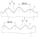
- FIG. 4 is a schematic cross-sectional view showing another example of the concavo-convex structure on the resin layer side surface of the aluminum substrate.
- FIG. 5 is a graph showing an example of an alternating waveform current waveform diagram used for electrochemical surface roughening treatment of an aluminum substrate.
- FIG. 6 is a schematic view showing an example of a radial cell in an electrochemical surface roughening process using alternating current in the production of an aluminum substrate.
- a numerical range expressed using “to” means a range including numerical values described before and after “to” as a lower limit value and an upper limit value.
- the colored aluminum plate of the present invention has an aluminum substrate and a resin layer provided on the aluminum substrate.
- the resin layer of the colored aluminum plate of the present invention contains inorganic particles having two or more peaks in the particle size distribution on a volume basis, and contains inorganic particles having two to five peaks. It is more preferable to contain inorganic particles having 2 to 3 peaks, and still more preferable to include inorganic particles having 2 peaks.
- the colored aluminum plate of the present invention has an arithmetic average roughness Ra of 0.1 to 0.8 ⁇ m on the surface on which the resin layer of the aluminum substrate is provided (hereinafter also referred to as “resin layer side surface”).
- the colored aluminum plate of the present invention has a concavo-convex structure in which the resin layer side surface of the aluminum substrate includes a concave portion having an average opening diameter of more than 5 ⁇ m and not more than 100 ⁇ m, and an unevenness having a concave portion having an average opening diameter of more than 0.5 ⁇ m and not more than 5 ⁇ m.
- the structure and at least one concavo-convex structure (hereinafter also referred to as “predetermined concavo-convex structure”) selected from the group consisting of a concavo-convex structure including a concavo-convex structure having an average opening diameter of more than 0.01 ⁇ m and 0.5 ⁇ m or less. It is preferable.
- a colored aluminum 10 shown in FIG. 1 includes an aluminum base 1 and a resin layer 2 provided on the aluminum base 1. Further, in the colored aluminum plate 10 shown in FIG. 1, the resin layer 2 contains the inorganic pigment 3 composed of the first inorganic particles 3a and the second inorganic particles 3b. Further, in the colored aluminum plate 10 shown in FIG. 1, the arithmetic average roughness Ra of the resin layer side surface 4 of the aluminum base 1 is 0.1 to 0.8 ⁇ m, and the resin layer side surface 4 of the aluminum base 1 is It has a predetermined uneven structure.
- the aluminum base material which the colored aluminum plate of the present invention has is not particularly limited. Specific examples thereof include a pure aluminum base material; an alloy base material containing aluminum as a main component (greater than 50% by mass) and a trace amount of foreign elements.
- the aluminum constituting the substrate preferably has a purity of 97% or more, more preferably 98% or more, still more preferably 99% or more, from the viewpoint of the uniformity of the surface treatment described later. 5% or more is particularly preferable.
- the shape of an aluminum base material is plate shape or sheet shape.
- the thickness of the aluminum substrate is not particularly limited because it can be appropriately designed according to the use of the colored aluminum plate, but the average thickness is 0.006 to 10 mm from the viewpoint of ease of handling and workability. It is preferably 0.01 to 5 mm, more preferably 0.05 to 2.5 mm.
- the “average thickness” of the aluminum substrate was calculated as an average value obtained by measuring the thickness of the aluminum substrate at 10 points with a high-precision digimatic micrometer (Mitutoyo, MDH-25M).
- the resin layer side surface of the aluminum substrate preferably has an arithmetic average roughness Ra of 0.1 to 0.8 ⁇ m, preferably 0.1 to 0.6 ⁇ m, because of good adhesion to the resin layer. It is more preferable that the thickness is 0.2 to 0.5 ⁇ m.
- the arithmetic average roughness Ra is an arithmetic average based on JIS B0601: 2001, measured using a stylus type surface roughness meter (for example, a surface roughness measuring machine SJ-401 manufactured by Mitutoyo Corporation). It is roughness.
- the resin layer side surface of the aluminum base material has a concave-convex structure (hereinafter, also referred to as “large wave structure”), average, including concave portions having an average opening diameter of more than 5 ⁇ m and not more than 100 ⁇ m, because of good adhesion to the resin layer.
- large wave structure concave-convex structure
- Concave and concavo-convex structure (hereinafter, also referred to as “medium wave structure”) having a recess having an opening diameter of more than 0.5 ⁇ m and not more than 5 ⁇ m, and a concavo-convex structure having a recess having an average opening diameter of more than 0.01 ⁇ m and not more than 0.5 ⁇ m (hereinafter referred to as “medium wave structure”) And at least one concavo-convex structure selected from the group consisting of “small wave structure”).
- the measuring method of the average aperture diameter of the large wave structure, the medium wave structure, and the small wave structure is as follows. (1) performs an average opening diameter stylus 2 dimensional roughness measurement in roughness meter large wave structure, the average peak distance S m as defined in ISO4287 were measured 5 times, and the mean opening diameter and the average value .
- the average opening diameter of the large wave structure is preferably 8 to 80 ⁇ m, and more preferably 10 to 70 ⁇ m.
- (2) Average aperture diameter of medium wave structure The surface of an aluminum substrate was photographed at a magnification of 2000 times from directly above using a high-resolution scanning electron microscope (SEM). At least 50 concave portions having a medium wave structure are extracted, and the diameter is read to obtain the opening diameter, and the average opening diameter is calculated.
- the average opening diameter of the medium wave structure is preferably 1 to 5 ⁇ m, and more preferably 2 to 4 ⁇ m.
- (3) Average aperture diameter (average wavelength) of the small wave structure Using a high-resolution scanning electron microscope (SEM), the surface of the aluminum substrate was photographed from directly above at a magnification of 50000 times. In the obtained SEM photograph, at least 50 concave portions having a small wave structure were extracted, and the diameter was read. And calculate the average opening diameter.
- the average opening diameter of the small wave structure is preferably 0.02 to 0.40 ⁇ m, and more preferably 0.05 to 0.20 ⁇ m.
- the resin layer side surface 4 of the aluminum substrate 1 shown in FIG. 2 has a surface of a concavo-convex structure (large wave structure) 5 including a concave portion 5a having an average opening diameter of more than 5 ⁇ m and not more than 100 ⁇ m.
- the opening diameter of the recessed part 5a is the diameter of the recessed part 5a (circumferentially connected to the periphery forming the recessed part 5a), and the average opening diameter is the average thereof.
- the concavo-convex structure including the concave portion may be a wave-shaped structure as shown in FIG. 2, and the concave portion repeating structure in which the convex portion 5b is formed of a flat portion as shown in FIG. It may be.
- the resin layer side surface 4 of the aluminum substrate 1 has a concave portion 5a and a convex portion having an average opening diameter of more than 5 ⁇ m and not more than 100 ⁇ m.
- the concavo-convex structure (large wave structure) 5 including 5b has a concavo-convex structure in which the concavo-convex structure (medium wave structure) 6 including the concave portions 6a and the convex portions 6b having an average opening diameter of more than 0.5 ⁇ m and 5 ⁇ m or less is superimposed. It is preferable.
- FIG. 1 As shown in FIG.
- the concavo-convex structure in which the medium wave structure is superimposed on the large wave structure is such that each of the large wave structure and the medium wave structure forms a substantially sinusoidal waveform and is one as a whole (large wave structure). It is preferable to constitute a substantially sine waveform.
- the method for producing the aluminum substrate is not particularly limited, but when the arithmetic average roughness Ra of the resin layer side surface is adjusted to a range of 0.1 to 0.8 ⁇ m, and / or the uneven structure described above on the resin layer side surface.
- a method of performing a surface treatment including a roughening treatment can be used.
- ⁇ Surface treatment> As a representative method for forming the above-described surface shape, for example, an aluminum substrate is subjected to an alkali etching treatment, an acid desmutting treatment, and an electrochemical surface roughening treatment using an electrolytic solution in sequence; Examples include, but are not limited to, a method in which an alkali etching treatment, a desmutting treatment with an acid, and an electrochemical surface roughening treatment using different electrolytic solutions are performed a plurality of times; In these methods, after the electrochemical surface roughening treatment, an alkali etching treatment and an acid desmutting treatment may be further performed.
- an electrolytic solution mainly composed of nitric acid is used in order to form a surface shape having a large wave structure or a medium wave structure.
- an electrolytic solution mainly composed of nitric acid is used in order to form a surface shape having a small wave structure.
- electrochemical surface roughening using an electrolyte mainly composed of hydrochloric acid can be mentioned in order to form a surface shape having a small wave structure.
- electrolytic solution mainly composed of nitric acid is used, and after an electrochemical surface roughening treatment with a reduced frequency, nitric acid is mainly formed.
- a method of applying an electrochemical surface roughening treatment with an increased frequency using an electrolytic solution; an electrochemical surface roughening treatment using an electrolytic solution mainly composed of nitric acid and increasing the total amount of electricity involved in the anode reaction The method of forming only in a lump by performing only the above; In addition, in order to form a surface shape in which a large wave structure and a small wave structure are superimposed, for example, an electrolytic solution mainly composed of nitric acid is used, an electrochemical surface roughening treatment with a reduced frequency is performed, and then hydrochloric acid is mainly formed.
- a method of performing an electrochemical surface roughening treatment using an electrolytic solution mainly composed of hydrochloric acid is preferable.
- a method of performing an electrochemical surface roughening treatment using a liquid is preferable.
- each step of the surface treatment will be described in detail.
- electrochemical roughening treatment For the electrochemical surface roughening treatment (hereinafter also referred to as “electrolytic surface roughening treatment”), an electrolytic solution used for the electrochemical surface roughening treatment using a normal alternating current can be used. Among them, it is preferable to use an electrolytic solution mainly composed of hydrochloric acid or nitric acid because the above-described surface shape can be easily obtained.
- Electrolytic surface roughening can be performed according to, for example, the electrochemical grain method (electrolytic grain method) described in Japanese Patent Publication No. 48-28123 and British Patent No. 896,563.
- This electrolytic grain method uses a sinusoidal alternating current, but it may be performed using a special waveform as described in JP-A-52-58602. Further, the waveform described in JP-A-3-79799 can also be used.
- the methods described in JP-A-3-267400 and JP-A-1-141094 can also be applied.
- JP-A-52-58602, JP-A-52-152302, JP-A-53-12738, JP-A-53-12739, JP-A-53-32821, JP-A-53-32222, JP 53-32833, JP 53-32824, JP 53-32825, JP 54-85802, JP 55-122896, JP 55-13284, JP 48-28123, JP-B-51-7081, JP-A-52-13338, JP-A-52-133840, JP-A-52-133844, JP-A-52-133845, JP-A-53- Nos. 149135 and 54-146234 can also be used.
- the concentration of the acidic solution is preferably 0.5 to 2.5% by mass, but it is particularly preferably 0.7 to 2.0% by mass in consideration of use in the smut removal treatment.
- the liquid temperature is preferably 20 to 80 ° C., more preferably 30 to 60 ° C.
- An aqueous solution mainly composed of hydrochloric acid or nitric acid is an aqueous solution of hydrochloric acid or nitric acid with a concentration of 1 to 100 g / L, such as nitric acid compounds having nitrate ions such as aluminum nitrate, sodium nitrate and ammonium nitrate, or aluminum chloride, sodium chloride and ammonium chloride.
- nitric acid compounds having hydrochloric acid ions can be used by adding in a range from 1 g / L to saturation.
- the metal contained in aluminum alloys such as iron, copper, manganese, nickel, titanium, magnesium, a silica, may melt
- a solution obtained by adding aluminum chloride, aluminum nitrate or the like to an aqueous solution of hydrochloric acid or nitric acid having a concentration of 0.5 to 2% by mass so that aluminum ions are 3 to 50 g / L is preferably used.
- the compound capable of forming a complex with Cu include ammonia; hydrogen atom of ammonia such as methylamine, ethylamine, dimethylamine, diethylamine, trimethylamine, cyclohexylamine, triethanolamine, triisopropanolamine, EDTA (ethylenediaminetetraacetic acid). And amines obtained by substituting with a hydrocarbon group (aliphatic, aromatic, etc.); metal carbonates such as sodium carbonate, potassium carbonate, potassium hydrogen carbonate and the like.
- ammonium salts such as ammonium nitrate, ammonium chloride, ammonium sulfate, ammonium phosphate, and ammonium carbonate are also included.
- the temperature is preferably 10 to 60 ° C, more preferably 20 to 50 ° C.
- the AC power source wave used for the electrochemical surface roughening treatment is not particularly limited, and a sine wave, a rectangular wave, a trapezoidal wave, a triangular wave or the like is used, but a rectangular wave or a trapezoidal wave is preferable, and a trapezoidal wave is particularly preferable.
- a trapezoidal wave means what was shown in FIG. In this trapezoidal wave, the time (TP) until the current reaches a peak from zero is preferably 1 to 3 msec. If it is less than 1 msec, processing irregularities such as chatter marks that occur perpendicular to the traveling direction of the aluminum base material are likely to occur.
- TP exceeds 3 msec, especially when a nitric acid electrolyte is used, it is easily affected by trace components in the electrolyte typified by ammonium ions and the like that spontaneously increase by electrolytic treatment, and uniform graining is performed. It becomes hard to be broken.
- a trapezoidal wave AC duty ratio of 1: 2 to 2: 1 can be used. However, as described in Japanese Patent Laid-Open No. 5-195300, in an indirect power feeding method that does not use a conductor roll for aluminum. A duty ratio of 1: 1 is preferable.
- a trapezoidal AC frequency of 0.1 to 120 Hz can be used, but 50 to 70 Hz is preferable in terms of equipment. When the frequency is lower than 50 Hz, the carbon electrode of the main electrode is easily dissolved, and when the frequency is higher than 70 Hz, it is easily affected by an inductance component on the power supply circuit, and the power supply cost is increased.
- One or more AC power supplies can be connected to the electrolytic cell.
- 11 is an aluminum substrate
- 12 is a radial drum roller
- 13a and 13b are main poles
- 14 is an electrolytic treatment solution
- 15 is an electrolyte supply port
- 16 is a slit.
- 17 is an electrolyte passage
- 18 is an auxiliary anode
- 19a and 19b are thyristors
- 20 is an AC power source
- 21 is a main electrolytic cell
- 22 is an auxiliary anode cell.
- the ratio of the amount of electricity involved in the cathodic reaction and the anodic reaction is preferably 0.3 to 0.95.
- electrolytic cell electrolytic cells used for known surface treatments such as a vertical type, a flat type, and a radial type can be used, but a radial type electrolytic cell as described in JP-A-5-195300 is particularly preferable.
- the electrolytic solution passing through the electrolytic cell may be parallel to the traveling direction of the aluminum web or may be a counter.
- An electrochemical roughening treatment using an electrolytic solution mainly composed of nitric acid can form a medium wave structure having an average opening diameter of more than 0.5 ⁇ m and not more than 5 ⁇ m.
- the electrolytic reaction is concentrated, and a large wave structure having a wavelength exceeding 5 ⁇ m is also generated.
- the total amount of electricity involved in the anodic reaction of the aluminum substrate at the end of the electrolytic reaction is preferably 1 to 1000 C / dm 2 , and preferably 50 to 300 C / dm 2. 2 is more preferable.
- the current density at this time is preferably 20 to 100 A / dm 2 .
- electrolysis is performed at 30 to 60 ° C. using a nitric acid electrolytic solution having a high concentration, for example, a nitric acid concentration of 15 to 35% by mass, or a high temperature using a nitric acid electrolytic solution having a nitric acid concentration of 0.7 to 2% by mass.
- a small wave structure having an average wavelength of 0.20 ⁇ m or less can be formed by performing electrolysis at 80 ° C. or higher.
- the total amount of electricity involved in the anodic reaction of the aluminum substrate at the end of the electrolytic reaction is preferably 1 to 100 C / dm 2 , and preferably 20 to 70 C / dm 2. It is more preferable that The current density at this time is preferably 20 to 50 A / dm 2 .
- a large crater-like swell is simultaneously formed by increasing the total amount of electricity involved in the anode reaction to 400 to 2000 C / dm 2. It is also possible. In this case, a fine small-wave structure having an average opening diameter of more than 0.01 ⁇ m and not more than 0.5 ⁇ m is generated on the entire surface by being superimposed on a large wave structure having an average opening diameter of more than 5 ⁇ m and not more than 100 ⁇ m.
- cathodic electrolysis treatment it is preferable to perform the cathodic electrolysis treatment on the aluminum substrate before and / or after the electrolytic surface roughening treatment performed in the electrolytic solution such as nitric acid and hydrochloric acid.
- the cathodic electrolysis treatment smut is generated on the surface of the aluminum base material, and hydrogen gas is generated to enable more uniform electrolytic surface roughening treatment.
- the cathodic electrolysis treatment is carried out in an acidic solution at a cathode electric quantity of preferably 3 to 80 C / dm 2 , more preferably 5 to 30 C / dm 2 .
- the electrolytic solution may be the same as or different from the solution used in the electrolytic surface roughening treatment.
- the alkali etching treatment is a treatment for dissolving the surface layer by bringing the aluminum base material into contact with an alkali solution.
- the alkali etching treatment performed before the electrolytic surface roughening treatment is performed for the purpose of removing rolling oil, dirt, natural oxide film, and the like on the surface of the aluminum substrate.
- the etching amount of the alkali etching treatment is preferably 0.05 to 10 g / m 2 , and more preferably 1 to 5 g / m 2 . If the etching amount is less than 0.05 g / m 2 , rolling oil, dirt, natural oxide film, etc. may remain on the surface, so that a uniform wave structure cannot be generated in the subsequent electrolytic surface roughening treatment. May occur. On the other hand, when the etching amount is 1 to 10 g / m 2 , the surface of the rolling oil, dirt, natural oxide film, etc. are sufficiently removed. An etching amount exceeding the above range is economically disadvantageous.
- the alkaline etching treatment performed immediately after the electrolytic surface roughening treatment is performed for the purpose of dissolving the smut generated in the acidic electrolyte and dissolving the edge portion of the wave structure formed by the electrolytic surface roughening treatment. Is called. Since the wave structure formed by the electrolytic surface roughening treatment differs depending on the type of the electrolyte, the optimum etching amount varies. However, the etching amount of the alkali etching treatment performed after the electrolytic surface roughening treatment is 0.1 to 5 g / m 2 is preferred. When a nitric acid electrolyte is used, the etching amount needs to be set larger than when a hydrochloric acid electrolyte is used. When the electrolytic surface roughening treatment is performed a plurality of times, an alkali etching treatment can be performed as necessary after each treatment.
- Examples of the alkali used in the alkaline solution include caustic alkali and alkali metal salts.
- caustic alkali include caustic soda and caustic potash.
- alkali metal salts include alkali metal silicates such as sodium silicate, sodium silicate, potassium metasilicate, and potassium silicate; alkali metal carbonates such as sodium carbonate and potassium carbonate; sodium aluminate and alumina.
- Alkali metal aluminates such as potassium acid; alkali metal aldones such as sodium gluconate and potassium gluconate; dibasic sodium phosphate, dibasic potassium phosphate, tribasic sodium phosphate, tertiary potassium phosphate, etc.
- An alkali metal hydrogen phosphate is mentioned.
- a caustic alkali solution and a solution containing both a caustic alkali and an alkali metal aluminate are preferable from the viewpoint of high etching rate and low cost.
- an aqueous solution of caustic soda is preferable.
- the concentration of the alkaline solution can be determined according to the etching amount, but is preferably 1 to 50% by mass, more preferably 10 to 35% by mass.
- the concentration of aluminum ions is preferably 0.01 to 10% by mass, and more preferably 3 to 8% by mass.
- the temperature of the alkaline solution is preferably 20 to 90 ° C.
- the treatment time is preferably 1 to 120 seconds.
- Examples of the method of bringing the aluminum base material into contact with the alkaline solution include a method in which the aluminum base material is passed through a tank containing the alkaline solution, a method in which the aluminum base material is immersed in a tank containing the alkaline solution, and alkali.
- the method of spraying a solution on the surface of an aluminum base material is mentioned.
- pickling is preferably performed in order to remove dirt (smut) remaining on the surface.
- the acid used include nitric acid, sulfuric acid, phosphoric acid, chromic acid, hydrofluoric acid, and borohydrofluoric acid.
- the desmutting treatment is performed, for example, by bringing the aluminum base material into contact with an acidic solution (containing aluminum ions of 0.01 to 5% by mass) having a concentration of 0.5 to 30% by mass such as hydrochloric acid, nitric acid, and sulfuric acid. Do.
- the method of bringing the aluminum base material into contact with the acidic solution examples include a method in which the aluminum base material is passed through a tank containing the acidic solution, a method in which the aluminum base material is immersed in a tank containing the acidic solution, The method of spraying a solution on the surface of an aluminum base material is mentioned.
- the acidic solution is mainly composed of an aqueous solution mainly composed of nitric acid or an aqueous solution mainly composed of hydrochloric acid discharged in the above-described electrolytic surface-roughening treatment, or sulfuric acid discharged in an anodic oxidation process described later. It is possible to use a waste solution of an aqueous solution.
- the temperature of the desmut treatment is preferably 25 to 90 ° C.
- the processing time is preferably 1 to 180 seconds.
- Aluminum and aluminum alloy components may be dissolved in the acidic solution used for the desmut treatment.
- the surface of the aluminum base material may be subjected to a mechanical surface roughening treatment such as brush grain.
- the resin layer which the colored aluminum plate of the present invention has is a layer which contains a resin material (binder) and an inorganic pigment and is provided on the above-described aluminum substrate.
- the resin layer is made of an acrylic resin, a polyester resin, a polyurethane resin, a polyolefin resin, and silicone because the flexibility of the resin layer is improved and the moldability becomes better. It is preferable to contain at least one resin material selected from the group consisting of a series resin. Among these, it is preferable to contain an acrylic resin or a urethane resin, and it is more preferable to contain an acrylic resin.
- the acrylic resin include polymerization of acrylic monomers such as methyl methacrylate, methyl acrylate, ethyl methacrylate, ethyl acrylate, butyl acrylate, 2-ethylhexyl acrylate, hydroxymethyl acrylate, hydroxyethyl acrylate, and glycidyl methyl acrylate.
- the polymer which was made is mentioned.
- the acrylic resin is a copolymer of the above-mentioned acrylic monomer and other copolymerizable monomers such as acrylic acid, methacrylic acid, itaconic acid, styrene, acrylonitrile, vinyl acetate, acrylamide, and divinylbenzene. There may be.
- the polyurethane resin examples include a polyurethane resin obtained by a reaction of a diisocyanate component, a diol component, and, if necessary, a chain extender such as a polyvalent amine.
- the polyurethane resin may be a polyurethane resin obtained by a reaction using a monomer component having a hydrophilic group as at least a part of these monomer components.
- the content of such a resin material is preferably 20 to 80% by mass, and more preferably 30 to 60% by mass with respect to the mass of the resin layer.
- the inorganic pigment contained in the resin layer is not particularly limited as long as it has two or more peaks in the particle size distribution on a volume basis, and white inorganic pigments, black inorganic pigments, and other color inorganic pigments may be used. it can. Of these, black or white inorganic pigments are preferred, and white inorganic pigments are more preferred.
- particle size distribution on a volume basis means that a dispersion liquid in which an inorganic pigment contained in a resin layer is dispersed and a resin material is dissolved or removed is prepared by a laser diffraction / scattering method (microtrack method).
- the measured particle size distribution refers to, for example, a laser diffraction / scattering particle size distribution measuring device (Microtrack BlueRaytrac) manufactured by Microtrack Bell Co., Ltd.
- the cross section of the resin layer is observed with a scanning electron microscope (SEM), and an SEM image in which the magnification is changed according to the particle diameter of the inorganic pigment is taken.
- SEM scanning electron microscope
- the obtained SEM image is subjected to image analysis, and a graph obtained from the particle size and frequency (number) of the inorganic pigment can be estimated as the particle size distribution.
- the inorganic pigment preferably contains two or more kinds of inorganic particles for reasons such as high reflectance in the entire visible light region, such as titanium dioxide (TiO 2 ) and silicon dioxide (SiO 2 ). And at least two kinds of white inorganic pigments selected from the group consisting of aluminum oxide (Al 2 O 3 ) are more preferable. Further, it is more preferable to use Al 2 O 3 together with TiO 2 because the whiteness is increased and the metallic luster can be adjusted.
- the average particle diameter of the inorganic pigment is preferably from 0.01 to 100 ⁇ m, more preferably from 0.01 to 55 ⁇ m. For reasons such as increasing the light scattering efficiency, 0.01% More preferably, it is ⁇ 25 ⁇ m.
- the “average particle size” means the average value of the particle size, and the inorganic pigment contained in the resin layer is dispersed, and a dispersion liquid in which the resin material is dissolved or removed is prepared. The 50% volume cumulative diameter (D50) measured using a particle size distribution measuring device.
- the cross section of the resin layer is observed by SEM, the obtained SEM image is subjected to image analysis, and the average calculated from the particle size and frequency (number) of the inorganic pigment
- the diameter can be estimated as the average particle diameter.
- the particle diameter that is the basis for calculating the average value is an average value obtained by dividing the total value of the major axis and the minor axis by 2, and when it is a perfect circle, Refers to the diameter.
- the content of such an inorganic pigment is preferably 10 to 70% by mass and more preferably 30 to 60% by mass with respect to the mass of the resin layer. Further, the content of the inorganic pigment is preferably 12.5 to 300 parts by mass, more preferably 50 to 200 parts by mass with respect to 100 parts by mass of the resin material.
- the resin layer may contain other components, and examples of the other components include a crosslinking agent, a surfactant, and a filler.
- crosslinking agent examples include epoxy-based, isocyanate-based, melamine-based, carbodiimide-based, and oxazoline-based crosslinking agents.
- a crosslinking agent having a reactive group that reacts with a hydroxyl group is preferable, a crosslinking agent having a hydrolyzable group is more preferable, and a crosslinking agent having an isocyanate group is still more preferable.
- the cross-linking agent preferably has an organic functional group other than a reactive group that reacts with a hydroxyl group.
- the crosslinking agent is selected from the group consisting of an amino group, an epoxy group, a methacryl group, a vinyl group, and a mercapto group. It preferably has at least one organic functional group.
- the content in the case of containing an arbitrary crosslinking agent is preferably 0.5 to 30 parts by mass, more preferably 3 to 15 parts by mass with respect to 100 parts by mass of the resin material.
- a known surfactant such as an anionic or nonionic surfactant can be used.
- the content is preferably 0.1 to 10 mg / m 2 , and more preferably 0.5 to 3 mg / m 2 .
- the total light transmittance in the wavelength region of 380 to 780 nm in the resin layer is preferably 80% or more, and more preferably 85 to 95%. preferable.
- the total light transmittance means the total light transmittance measured in accordance with the total light transmittance test method specified in JIS K 7136-1: 1997.
- the thickness of the resin layer is not particularly limited because it can be appropriately designed according to the use of the colored aluminum plate, etc. From the viewpoint of ease of handling and workability, the average thickness is preferably more than 5 ⁇ m and 100 ⁇ m or less. The thickness is more preferably 10 to 50 ⁇ m, and further preferably 15 to 45 ⁇ m.
- the “average thickness” of the resin layer is determined by cutting the resin layer with a focused ion beam (FIB) in the thickness direction and cross-sectioning the section with a field emission scanning electron microscope (Field Emission Scanning Electron). A surface photograph (magnification 50000 times) was taken with a Microscope: FE-SEM, and the average value obtained by measuring 10 points was calculated.
- FIB focused ion beam
- the surface of the resin layer has a lower gloss and a higher-grade metallic appearance, so that the arithmetic average roughness Ra is preferably 0.5 to 5.0 ⁇ m, More preferably, the thickness is 1.0 to 3.0 ⁇ m.
- the formation method of a resin layer is not specifically limited, It can form by well-known methods, such as application
- a coating method for example, a known coating method such as a gravure coater or a bar coater can be used.
- the coating solution may be an aqueous system using water as an application solvent, or a solvent system using an organic solvent such as toluene or methyl ethyl ketone. Among these, from the viewpoint of environmental burden, it is preferable to use water as a solvent.
- One type of coating solvent may be used alone, or a water-miscible organic solvent may be mixed with water.
- the colored aluminum plate of the present invention uses a white inorganic pigment as the above-mentioned inorganic pigment because of a good balance of performance such as coloring due to scattering of the inorganic pigment, surface metallic luster, and hardness of the resin layer.
- a white aluminum plate having a value of 80 or more is preferable.
- “L * value” means lightness (L * a * b * color system) measured using a spectral densitometer (FD-7, manufactured by Konica Minolta). * : SCE method).
- Example 1 [Aluminum substrate] An aluminum plate (1085 material, manufactured by UACJ) having a thickness of 0.5 mm and a width of 100 m was used.
- Titanium dioxide (Taipaque CR95, average particle size: 0.28 ⁇ m, Ishihara Sangyo Co., Ltd., solid content 100% by mass) 40 parts by mass / polyvinyl alcohol aqueous solution (10% by mass) (PVA-105, manufactured by Kuraray Co., Ltd.) 20.0 parts by mass Surfactant (Demol EP, manufactured by Kao Corporation, (Solid content: 25% by mass) 0.5 parts by mass and 39.5 parts by mass of distilled water ------------ ⁇
- alumina (Al 2 O 3 ) particles CW325-LV, manufactured by Sumitomo Chemical Co., Ltd.
- Example 2 instead of an aluminum substrate, an aluminum substrate having a concavo-convex structure on the surface was prepared by applying the following surface treatment to the surface of an aluminum plate (1085 material, manufactured by UACJ) having a thickness of 0.5 mm and a width of 100 m. A white aluminum plate was produced in the same manner as in Example 1 except that it was used.
- Electrochemical roughening treatment formation of large wave structure
- the electrolytic solution at this time was a nitric acid 10.4 g / L aqueous solution (containing aluminum ions 4.5 g / L), and the liquid temperature was 50 ° C.
- An electrochemical surface roughening treatment was performed using a carbon electrode as a counter electrode. Ferrite was used for the auxiliary anode.
- the electrolytic cell used was the one shown in FIG.
- the current density was 30 A / dm 2 at the peak current value, and the amount of electricity was 770 C / dm 2 in terms of the total amount of electricity when the aluminum foil was the anode. 5% of the current flowing from the power source was shunted to the auxiliary anode. Then, water washing by spraying was performed.
- the aluminum foil was subjected to an etching treatment at 32 ° C. using an aqueous solution having a caustic soda concentration of 26 mass% and an aluminum ion concentration of 6.5 mass%, and the aluminum foil was dissolved at 0.5 g / m 2.
- the smut component mainly composed of aluminum hydroxide generated when the electrochemical surface roughening treatment is performed using the alternating current of the previous stage is removed, and the edge portion of the generated medium wave structure is dissolved to the edge. The part was smoothed. Then, water washing by spraying was performed.
- Example 3 (1-1) Instead of the electrochemical surface roughening treatment (formation of a large wave structure), the following (1-2) electrochemical surface roughening treatment (medium wave structure formation) was performed, A white aluminum plate was produced in the same manner as in Example 2.
- (1-2) Electrochemical roughening treatment (formation of medium wave structure) First, an electrochemical roughening treatment was continuously performed using an alternating voltage of 60 Hz. The electrolytic solution at this time was a nitric acid 9.2 g / L aqueous solution (containing 4.5 g / L of aluminum ions) at a temperature of 50 ° C.
- the AC power supply waveform is the waveform shown in FIG.
- the time TP until the current value reaches a peak from zero is 0.8 msec
- the duty ratio is 1: 1
- a trapezoidal rectangular wave AC is used, with the carbon electrode as the counter electrode
- An electrochemical roughening treatment was performed. Ferrite was used for the auxiliary anode.
- the electrolytic cell used was the one shown in FIG.
- the current density was 25 A / dm 2 at the peak current value, and the amount of electricity was 185 C / dm 2 as the total amount of electricity when the aluminum foil was the anode. Then, water washing by spraying was performed.
- Example 4 (1-1) Instead of electrochemical surface roughening treatment (large wave structure formation), the following (1-3) electrochemical surface roughening treatment (small wave structure formation) was performed except that A white aluminum plate was produced in the same manner as in Example 2.
- (1-3) Electrochemical roughening treatment (formation of wavelet structure) First, an electrochemical roughening treatment was continuously performed using an alternating voltage of 60 Hz. The electrolytic solution at this time was a 8.2 g / L aqueous solution of hydrochloric acid (containing 4.5 g / L of aluminum ions) at a temperature of 35 ° C.
- the AC power supply waveform is the waveform shown in FIG.
- the time TP until the current value reaches a peak from zero is 0.8 msec
- the duty ratio is 1: 1
- a trapezoidal rectangular wave AC is used, with the carbon electrode as the counter electrode
- An electrochemical roughening treatment was performed. Ferrite was used for the auxiliary anode.
- the electrolytic cell used was the one shown in FIG.
- the current density was 25A / dm 2 at the peak current
- the quantity of electricity of the aluminum foil was 63C / dm 2 as the total quantity of electricity when the anode.
- water washing by spraying was performed.
- Example 5 A white aluminum plate was produced in the same manner as in Example 1 except that the resin layer forming coating solution 2 prepared by the following method was used in place of the resin layer forming coating solution 1.
- alumina (Al 2 O 3 ) particles CW325-LV, manufactured by Sumitomo Chemical Co., Ltd.
- Example 6 A white aluminum plate was produced in the same manner as in Example 1 except that the resin layer forming coating solution 3 prepared by the following method was used in place of the resin layer forming coating solution 1.
- Example 7 A white aluminum plate was produced in the same manner as in Example 1 except that the resin layer forming coating solution 4 prepared by the following method was used in place of the resin layer forming coating solution 1.
- Example 8 A white aluminum plate was produced in the same manner as in Example 1 except that the thickness of the resin layer was changed to 65 ⁇ m.
- Example 9 A white aluminum plate was produced in the same manner as in Example 1 except that the resin layer forming coating solution B was used in place of the resin layer forming coating solution A.
- Example 10 (1-1) Instead of electrochemical roughening treatment (formation of large wave structure), the following (1-4) electrochemical roughening treatment (collective formation of large wave structure and medium wave structure) is performed.
- a white aluminum plate was produced in the same manner as in Example 2 except that.
- an electrochemical roughening treatment was continuously performed using an alternating voltage of 60 Hz.
- the electrolytic solution at this time was a nitric acid 10.2 g / L aqueous solution (containing aluminum ions 4.5 g / L), and the liquid temperature was 33 ° C.
- the AC power supply waveform is the waveform shown in FIG.
- the time TP until the current value reaches a peak from zero is 0.8 msec
- the duty ratio is 1: 1
- a trapezoidal rectangular wave AC is used, with the carbon electrode as the counter electrode
- An electrochemical roughening treatment was performed. Ferrite was used for the auxiliary anode.
- the electrolytic cell used was the one shown in FIG.
- the current density was 30 A / dm 2 at the peak current value, and the amount of electricity was 612 C / dm 2 as the total amount of electricity when the aluminum foil was the anode.
- 5% of the current flowing from the power source was shunted to the auxiliary anode. Then, water washing by spraying was performed.
- Example 1 A white aluminum plate was produced in the same manner as in Example 3 except that after the above (3) desmut treatment was performed, the following (4) anodization treatment was performed and no resin layer was formed. (4) Anodizing treatment Next, anodizing treatment was performed using direct current. The electrolytic solution at this time was a 170 g / L aqueous solution of sulfuric acid (containing 7 g / L of aluminum ions) and a liquid temperature of 50 ° C. Electrochemical anodic oxidation treatment was performed using an aluminum electrode as a counter electrode.
- the current density was 20 A / dm 2 at the peak current value, and the amount of electricity was 2700 C / dm 2 in terms of the total amount of electricity when the aluminum foil was the anode. Then, water washing by spraying was performed.
- the film thickness of the anodized alumina film was about 10 ⁇ m.
- Example 2 A white aluminum plate was produced in the same manner as in Example 1 except that the resin layer forming coating solution 5 prepared by the following method was used in place of the resin layer forming layer coating solution 1. ⁇ Preparation of coating solution 5 for resin layer formation> Each component in the following composition was mixed to prepare a coating solution 5 for forming a resin layer.
- Example 3 A white aluminum plate was produced in the same manner as in Example 1 except that the resin layer forming coating solution A prepared in Example 1 was used in place of the resin layer forming layer coating solution 1.
- the anodized film formed on the surface of the aluminum base material by the anodizing treatment had a thickness of 9.3 ⁇ m and had a plurality of pores extending from the surface to the interface between the aluminum base material and the anodized film.
- the smallest pore diameter (minimum pore diameter) among the pores exposed on the surface was 170 nm.
- the depth of the pores corresponds to the thickness of the film.
- the thickness of the anodized film and the pore diameter were confirmed from a cross-sectional electron micrograph of the substrate including the anodized film and a surface electron micrograph of the anodized film.
- the aluminum substrate on which the anodized film was formed was immersed in warm water at 70 ° C. for 30 minutes and washed with water. Then, without drying, it was immersed for 30 minutes in the pigment composition for coloring (liquid temperature: 20 degreeC) of the following composition, and the anodized film of the aluminum base material was colored white.
- ⁇ Coloring pigment composition> White pigment particles: 75 parts by mass of titanium oxide (D80 particle size: 120 nm) Dispersant: 10 parts by mass of styrene acrylic resin (high loss 2008L, number average molecular weight: 5,000, PMC Seiko Chemical Co., Ltd.) Water: 100 Part by mass ⁇ Redox potential (ORP): 37 mV -PH: 8.88
- Pencil hardness The surface hardness of the produced white aluminum plate on the resin layer side was measured. Specifically, it was measured using a pencil hardness tester (manufactured by Allgood) according to “Scratch hardness (pencil method)” of JIS K5600-5-4. The results are shown in Table 1 below.
- (2) Whiteness The whiteness L * value on the resin layer side of the produced white aluminum plate was measured using a spectral densitometer (FD-7, manufactured by Konica Minolta). The results are shown in Table 1 below. In addition, if whiteness is 80 or more, it can be evaluated that it is colored white.
- the peeled square is 1 square or more.
- (4) Glossiness The glossiness on the resin layer side of the produced white aluminum plate was measured with a glossiness meter (IG-320, manufactured by Horiba, Ltd.) in accordance with JIS K 5600-4-7 and JIS Z 8741. The results are shown in Table 1 below. In addition, in the glossiness when the light incident angle is 85 °, less than 5% is set as a practically acceptable range.
- Example 1 when a resin layer containing an inorganic pigment is provided so that there are two or more peaks in the particle size distribution of the inorganic pigment on the volume basis, the glossiness becomes low and the metallic tone is lost.
- Examples 1 to 10 Further, from the results of Examples 1 to 4 and 10, it is found that the Ra of the aluminum base is 0.2 to 0.5 ⁇ m and the medium wave structure or the small wave structure is present, whereby the adhesion with the resin layer is improved. It turned out to be better. Furthermore, it was found from the comparison between Example 1 and Example 7 that the glossiness was lower when TiO 2 and SiO 2 were contained.
- Example 1 From comparison between Example 1 and Example 8, it was found that the glossiness was lower when the average thickness of the resin layer was 10 to 50 ⁇ m. Similarly, it was found from the comparison between Example 1 and Example 9 that the glossiness is lower when the resin layer contains an acrylic resin.
Landscapes
- Chemical & Material Sciences (AREA)
- Engineering & Computer Science (AREA)
- Chemical Kinetics & Catalysis (AREA)
- Materials Engineering (AREA)
- Metallurgy (AREA)
- Organic Chemistry (AREA)
- Electrochemistry (AREA)
- Mechanical Engineering (AREA)
- Life Sciences & Earth Sciences (AREA)
- Wood Science & Technology (AREA)
- Laminated Bodies (AREA)
Abstract
本発明は、適度な光沢度を有する着色アルミニウム板を提供することを課題とする。本発明の着色アルミニウム板は、アルミニウム基材と、アルミニウム基材上に設けられる樹脂層とを有する、着色アルミニウム板であって、樹脂層が無機顔料を含有し、無機顔料の体積基準での粒度分布において、2以上のピークが存在する、着色アルミニウム板である。
Description
本発明は、着色アルミニウム板に関する。
アルミニウム製品またはアルミニウム合金製品(例えば、携帯電話の外装部材など)に用いられるアルミニウム板は、表面保護、外観の美麗さを高めるために着色されている。
アルミニウム板を着色する方法として、例えば、特許文献1には、「(i)アルミニウムまたはアルミニウム合金からなる基材をリン酸を含む処理溶液中で陽極酸化を行って基材表面に複数の細孔を有する陽極酸化皮膜を形成する工程と、(ii)基材を40~100℃の温水により処理する工程と、(iii)基材を顔料粒子、分散剤および水を含む着色用顔料組成物に浸漬して基材表面の陽極酸化皮膜の複数の細孔に顔料粒子を充填し、着色する工程とを含むことを特徴とする着色アルミニウム製品または着色アルミニウム合金製品の製造方法。」が記載されており([請求項1])、黒、赤、青、黄、緑および白色のいずれかに着色された着色アルミニウム製品または着色アルミニウム合金製品が記載されている([請求項11]~[請求項16])。
本発明者らは、特許文献1に記載された製造方法について検討したところ、製造した着色アルミニウム製品または着色アルミニウム合金製品は、光沢度が高くなり過ぎ、高級感のある金属調外観、すなわち、つやが消えた金属調の質感を有する外観を有しているとは言い難いことを明らかとした。
そこで、本発明は、適度な光沢度を有する着色アルミニウム板を提供することを課題とする。
本発明者らは、上記課題を達成すべく鋭意研究した結果、アルミニウム基材上に、体積基準での粒度分布において2以上のピークが存在する無機顔料を含有させた樹脂層を設けることにより、適度な光沢度を有する着色アルミニウム板となることを見出し、本発明を完成させた。
すなわち、以下の構成により上記課題を達成することができることを見出した。
すなわち、以下の構成により上記課題を達成することができることを見出した。
[1] アルミニウム基材と、アルミニウム基材上に設けられる樹脂層とを有する、着色アルミニウム板であって、
樹脂層が無機顔料を含有し、
無機顔料の体積基準での粒度分布において、2以上のピークが存在する、着色アルミニウム板。
[2] 樹脂層が、アクリル系樹脂、ポリエステル系樹脂、ポリウレタン系樹脂、ポリオレフィン系樹脂、および、シリコーン系樹脂からなる群から選択される少なくとも1種の樹脂材料を含有する、[1]に記載の着色アルミニウム板。
[3] 無機顔料が、2種以上の無機粒子を含有する、[1]または[2]に記載の着色アルミニウム板。
[4] 無機顔料の平均粒子径が0.01~100μmである、[1]~[3]のいずれかに記載の着色アルミニウム板。
[5] アルミニウム基材の樹脂層側の表面の算術平均粗さRaが0.1~0.8μmである、[1]~[4]のいずれかに記載の着色アルミニウム板。
[6] 無機顔料が、TiO2、SiO2、および、Al2O3からなる群から選択される少なくとも2種を含有する、[1]~[5]のいずれかに記載の着色アルミニウム板。
[7] 樹脂層の平均厚みが5μm超100μm以下である、[1]~[6]のいずれかに記載の着色アルミニウム板。
[8] アルミニウム基材の平均厚みが0.006~10mmである、[1]~[7]のいずれかに記載の着色アルミニウム板。
[9] アルミニウム基材の樹脂層側の表面が、平均開口径が5μm超100μm以下の凹部を含む凹凸構造、平均開口径が0.5μm超5μm以下の凹部を含む凹凸構造、および、平均開口径が0.01μm超0.5μm以下の凹部を含む凹凸構造からなる群から選択される少なくとも1つの凹凸構造を有する、[1]~[8]のいずれかに記載の着色アルミニウム板。
[10] アルミニウム基材の樹脂層側の表面が、平均開口径が5μm超100μm以下の凹部を含む凹凸構造に、平均開口径が0.5μm超5μm以下の凹部を含む凹凸構造が重畳された凹凸構造である、[1]~[9]のいずれかに記載の着色アルミニウム板。
[11] 樹脂層が、少なくともアクリル系樹脂を含有する、[1]~[10]のいずれかに記載の着色アルミニウム板。
[12] 無機顔料が、TiO2およびSiO2を含有する、[1]~[11]のいずれかに記載の着色アルミニウム板。
[13] 樹脂層の平均厚みが10~50μmである、[1]~[12]のいずれかに記載の着色アルミニウム板。
[14] 樹脂層における380~780nmの波長領域の全光線透過率が80%以上である、[1]~[13]のいずれかに記載の着色アルミニウム板。
[15] 白色度L*値が80以上である、[1]~[14]のいずれかに記載の着色アルミニウム板。
樹脂層が無機顔料を含有し、
無機顔料の体積基準での粒度分布において、2以上のピークが存在する、着色アルミニウム板。
[2] 樹脂層が、アクリル系樹脂、ポリエステル系樹脂、ポリウレタン系樹脂、ポリオレフィン系樹脂、および、シリコーン系樹脂からなる群から選択される少なくとも1種の樹脂材料を含有する、[1]に記載の着色アルミニウム板。
[3] 無機顔料が、2種以上の無機粒子を含有する、[1]または[2]に記載の着色アルミニウム板。
[4] 無機顔料の平均粒子径が0.01~100μmである、[1]~[3]のいずれかに記載の着色アルミニウム板。
[5] アルミニウム基材の樹脂層側の表面の算術平均粗さRaが0.1~0.8μmである、[1]~[4]のいずれかに記載の着色アルミニウム板。
[6] 無機顔料が、TiO2、SiO2、および、Al2O3からなる群から選択される少なくとも2種を含有する、[1]~[5]のいずれかに記載の着色アルミニウム板。
[7] 樹脂層の平均厚みが5μm超100μm以下である、[1]~[6]のいずれかに記載の着色アルミニウム板。
[8] アルミニウム基材の平均厚みが0.006~10mmである、[1]~[7]のいずれかに記載の着色アルミニウム板。
[9] アルミニウム基材の樹脂層側の表面が、平均開口径が5μm超100μm以下の凹部を含む凹凸構造、平均開口径が0.5μm超5μm以下の凹部を含む凹凸構造、および、平均開口径が0.01μm超0.5μm以下の凹部を含む凹凸構造からなる群から選択される少なくとも1つの凹凸構造を有する、[1]~[8]のいずれかに記載の着色アルミニウム板。
[10] アルミニウム基材の樹脂層側の表面が、平均開口径が5μm超100μm以下の凹部を含む凹凸構造に、平均開口径が0.5μm超5μm以下の凹部を含む凹凸構造が重畳された凹凸構造である、[1]~[9]のいずれかに記載の着色アルミニウム板。
[11] 樹脂層が、少なくともアクリル系樹脂を含有する、[1]~[10]のいずれかに記載の着色アルミニウム板。
[12] 無機顔料が、TiO2およびSiO2を含有する、[1]~[11]のいずれかに記載の着色アルミニウム板。
[13] 樹脂層の平均厚みが10~50μmである、[1]~[12]のいずれかに記載の着色アルミニウム板。
[14] 樹脂層における380~780nmの波長領域の全光線透過率が80%以上である、[1]~[13]のいずれかに記載の着色アルミニウム板。
[15] 白色度L*値が80以上である、[1]~[14]のいずれかに記載の着色アルミニウム板。
本発明によれば、適度な光沢度を有する着色アルミニウム板を提供することができる。
以下、本発明について詳細に説明する。
以下に記載する構成要件の説明は、本発明の代表的な実施態様に基づいてなされることがあるが、本発明はそのような実施態様に限定されるものではない。
なお、本願明細書において、「~」を用いて表される数値範囲は、「~」の前後に記載される数値を下限値および上限値として含む範囲を意味する。
以下に記載する構成要件の説明は、本発明の代表的な実施態様に基づいてなされることがあるが、本発明はそのような実施態様に限定されるものではない。
なお、本願明細書において、「~」を用いて表される数値範囲は、「~」の前後に記載される数値を下限値および上限値として含む範囲を意味する。
本発明の着色アルミニウム板は、アルミニウム基材と、アルミニウム基材上に設けられる樹脂層とを有する。
本発明の着色アルミニウム板が有する樹脂層は、体積基準での粒度分布において2以上のピークが存在する無機粒子を含有しており、2~5のピークが存在する無機粒子を含有していることが好ましく、2~3のピークが存在する無機粒子を含有していることがより好ましく、2つのピークが存在ずる無機粒子を含有していることが更に好ましい。
また、本発明の着色アルミニウム板は、アルミニウム基材の樹脂層が設けられた側の表面(以下、「樹脂層側表面」ともいう。)の算術平均粗さRaが0.1~0.8μmであることが好ましい。
更に、本発明の着色アルミニウム板は、アルミニウム基材の樹脂層側表面が、平均開口径が5μm超100μm以下の凹部を含む凹凸構造、平均開口径が0.5μm超5μm以下の凹部を含む凹凸構造、および、平均開口径が0.01μm超0.5μm以下の凹部を含む凹凸構造からなる群から選択される少なくとも1つの凹凸構造(以下、「所定の凹凸構造」ともいう。)を有していることが好ましい。
本発明の着色アルミニウム板が有する樹脂層は、体積基準での粒度分布において2以上のピークが存在する無機粒子を含有しており、2~5のピークが存在する無機粒子を含有していることが好ましく、2~3のピークが存在する無機粒子を含有していることがより好ましく、2つのピークが存在ずる無機粒子を含有していることが更に好ましい。
また、本発明の着色アルミニウム板は、アルミニウム基材の樹脂層が設けられた側の表面(以下、「樹脂層側表面」ともいう。)の算術平均粗さRaが0.1~0.8μmであることが好ましい。
更に、本発明の着色アルミニウム板は、アルミニウム基材の樹脂層側表面が、平均開口径が5μm超100μm以下の凹部を含む凹凸構造、平均開口径が0.5μm超5μm以下の凹部を含む凹凸構造、および、平均開口径が0.01μm超0.5μm以下の凹部を含む凹凸構造からなる群から選択される少なくとも1つの凹凸構造(以下、「所定の凹凸構造」ともいう。)を有していることが好ましい。
図1に、本発明の着色アルミニウム板の一例を模式的な断面図で示す。
図1に示す着色アルミニウム10は、アルミニウム基材1と、アルミニウム基材1上に設けられる樹脂層2とを有する。
また、図1に示す着色アルミニウム板10は、樹脂層2が第1の無機粒子3aおよび第2の無機粒子3bからなる無機顔料3を含有している。
また、図1に示す着色アルミニウム板10は、アルミニウム基材1の樹脂層側表面4の算術平均粗さRaが0.1~0.8μmであり、アルミニウム基材1の樹脂層側表面4が所定の凹凸構造を有している。
図1に示す着色アルミニウム10は、アルミニウム基材1と、アルミニウム基材1上に設けられる樹脂層2とを有する。
また、図1に示す着色アルミニウム板10は、樹脂層2が第1の無機粒子3aおよび第2の無機粒子3bからなる無機顔料3を含有している。
また、図1に示す着色アルミニウム板10は、アルミニウム基材1の樹脂層側表面4の算術平均粗さRaが0.1~0.8μmであり、アルミニウム基材1の樹脂層側表面4が所定の凹凸構造を有している。
本発明においては、上述した通り、アルミニウム基材上に、体積基準での粒度分布において2以上のピークが存在する無機顔料を含有させた樹脂層を設けることにより、適度な光沢度を有する着色アルミニウム板となる。
これは、詳細には明らかではないが、本発明者らは以下のように推測している。
すなわち、体積基準での粒度分布において2以上のピークが存在する無機顔料を含有させることにより、樹脂層の表面における光散乱が増えたためであると考えられる。
以下、本発明の着色アルミニウム板の各構成要件について詳細に説明する。
これは、詳細には明らかではないが、本発明者らは以下のように推測している。
すなわち、体積基準での粒度分布において2以上のピークが存在する無機顔料を含有させることにより、樹脂層の表面における光散乱が増えたためであると考えられる。
以下、本発明の着色アルミニウム板の各構成要件について詳細に説明する。
[アルミニウム基材]
本発明の着色アルミニウム板が有するアルミニウム基材は、特に限定されず、その具体例としては、純アルミニウム基材;アルミニウムを主成分(50質量%超)とし、微量の異元素を含む合金基材;低純度のアルミニウム(例えば、リサイクル材料)に高純度アルミニウムを蒸着させた基材;シリコンウエハー、石英およびガラスなどの表面に、蒸着およびスパッタなどの方法により高純度アルミニウムを被覆させた基材;等が挙げられる。
また、基材を構成するアルミニウムは、後述する表面処理の均一性などの観点から、その純度が97%以上であるのが好ましく、98%以上がより好ましく、99%以上が更に好ましく、99.5%以上が特に好ましい。
また、アルミニウム基材の形状は、板状またはシート状であるのが好ましい。
本発明の着色アルミニウム板が有するアルミニウム基材は、特に限定されず、その具体例としては、純アルミニウム基材;アルミニウムを主成分(50質量%超)とし、微量の異元素を含む合金基材;低純度のアルミニウム(例えば、リサイクル材料)に高純度アルミニウムを蒸着させた基材;シリコンウエハー、石英およびガラスなどの表面に、蒸着およびスパッタなどの方法により高純度アルミニウムを被覆させた基材;等が挙げられる。
また、基材を構成するアルミニウムは、後述する表面処理の均一性などの観点から、その純度が97%以上であるのが好ましく、98%以上がより好ましく、99%以上が更に好ましく、99.5%以上が特に好ましい。
また、アルミニウム基材の形状は、板状またはシート状であるのが好ましい。
アルミニウム基材の厚さは、着色アルミニウム板の用途などに応じて適宜設計できるため特に限定されないが、取り扱いの容易性および作業性などの観点から、平均厚みが0.006~10mmであることが好ましく、0.01~5mmであることがより好ましく、0.05~2.5mmであることが更に好ましい。
ここで、アルミニウム基材の「平均厚み」は、アルミニウム基材の厚さを高精度デジマチックマイクロメータ(Mitsutoyo社製、MDH-25M)で10点測定した平均値として算出した。
ここで、アルミニウム基材の「平均厚み」は、アルミニウム基材の厚さを高精度デジマチックマイクロメータ(Mitsutoyo社製、MDH-25M)で10点測定した平均値として算出した。
〔樹脂層側表面〕
<算術平均粗さRa>
アルミニウム基材の樹脂層側表面は、樹脂層との密着性が良好となる理由から、算術平均粗さRaが、0.1~0.8μmであることが好ましく、0.1~0.6μmであることがより好ましく、0.2~0.5μmであることが更に好ましい。
ここで、算術平均粗さRaは、触針式の表面粗さ計(例えば、ミツトヨ社製の表面粗さ測定機SJ-401など)を用いて測定した、JIS B0601:2001に準拠する算術平均粗さである。
<算術平均粗さRa>
アルミニウム基材の樹脂層側表面は、樹脂層との密着性が良好となる理由から、算術平均粗さRaが、0.1~0.8μmであることが好ましく、0.1~0.6μmであることがより好ましく、0.2~0.5μmであることが更に好ましい。
ここで、算術平均粗さRaは、触針式の表面粗さ計(例えば、ミツトヨ社製の表面粗さ測定機SJ-401など)を用いて測定した、JIS B0601:2001に準拠する算術平均粗さである。
<凹凸構造>
アルミニウム基材の樹脂層側表面は、樹脂層との密着性が良好となる理由から、平均開口径が5μm超100μm以下の凹部を含む凹凸構造(以下、「大波構造」ともいう。)、平均開口径が0.5μm超5μm以下の凹部を含む凹凸構造(以下、「中波構造」ともいう。)、および、平均開口径が0.01μm超0.5μm以下の凹部を含む凹凸構造(以下、「小波構造」ともいう。)からなる群から選択される少なくとも1つの凹凸構造を有していることが好ましい。
アルミニウム基材の樹脂層側表面は、樹脂層との密着性が良好となる理由から、平均開口径が5μm超100μm以下の凹部を含む凹凸構造(以下、「大波構造」ともいう。)、平均開口径が0.5μm超5μm以下の凹部を含む凹凸構造(以下、「中波構造」ともいう。)、および、平均開口径が0.01μm超0.5μm以下の凹部を含む凹凸構造(以下、「小波構造」ともいう。)からなる群から選択される少なくとも1つの凹凸構造を有していることが好ましい。
ここで、上記大波構造、上記中波構造および上記小波構造の平均開口径の測定方法は、以下の通りである。
(1)大波構造の平均開口径
触針式粗さ計で2次元粗さ測定を行い、ISO4287に規定されている平均山間隔Smを5回測定し、その平均値を平均開口径とする。
なお、大波構造の平均開口径は、8~80μmであることが好ましく、10~70μmであることがより好ましい。
(2)中波構造の平均開口径
高分解能走査型電子顕微鏡(SEM)を用いてアルミニウム基材の表面を真上から倍率2000倍で撮影し、得られたSEM写真において、周囲が環状に連なっている中波構造の凹部を少なくとも50個抽出し、その直径を読み取って開口径とし、平均開口径を算出する。
なお、中波構造の平均開口径は、1~5μmであることが好ましく、2~4μmであることがより好ましい。
(3)小波構造の平均開口径(平均波長)
高分解能走査型電子顕微鏡(SEM)を用いてアルミニウム基材の表面を真上から倍率50000倍で撮影し、得られたSEM写真において、小波構造の凹部を少なくとも50個抽出し、その直径を読み取って開口径とし、平均開口径を算出する。
なお、小波構造の平均開口径は、0.02~0.40μmであることが好ましく、0.05~0.20μmであることがより好ましい。
(1)大波構造の平均開口径
触針式粗さ計で2次元粗さ測定を行い、ISO4287に規定されている平均山間隔Smを5回測定し、その平均値を平均開口径とする。
なお、大波構造の平均開口径は、8~80μmであることが好ましく、10~70μmであることがより好ましい。
(2)中波構造の平均開口径
高分解能走査型電子顕微鏡(SEM)を用いてアルミニウム基材の表面を真上から倍率2000倍で撮影し、得られたSEM写真において、周囲が環状に連なっている中波構造の凹部を少なくとも50個抽出し、その直径を読み取って開口径とし、平均開口径を算出する。
なお、中波構造の平均開口径は、1~5μmであることが好ましく、2~4μmであることがより好ましい。
(3)小波構造の平均開口径(平均波長)
高分解能走査型電子顕微鏡(SEM)を用いてアルミニウム基材の表面を真上から倍率50000倍で撮影し、得られたSEM写真において、小波構造の凹部を少なくとも50個抽出し、その直径を読み取って開口径とし、平均開口径を算出する。
なお、小波構造の平均開口径は、0.02~0.40μmであることが好ましく、0.05~0.20μmであることがより好ましい。
図2~図4に、アルミニウム基材の樹脂層側表面が有していてもよい任意の凹凸構造の一例を模式的な断面図で示す。
図2に示すアルミニウム基材1の樹脂層側表面4は、平均開口径5μm超100μm以下の凹部5aを含む凹凸構造(大波構造)5の表面を有するものである。
ここで、図2に示す通り、凹部5aの開口径は、凹部5a(凹部5aを形成する環状に連なる周囲)の直径であり、平均開口径とは、その平均である。
また、凹部を含む凹凸構造とは、図2に示すように波型の構造のものであってもよく、図3に示すように凸部5bが表面の平坦部分で構成される凹部の繰り返し構造であってもよい。
図2に示すアルミニウム基材1の樹脂層側表面4は、平均開口径5μm超100μm以下の凹部5aを含む凹凸構造(大波構造)5の表面を有するものである。
ここで、図2に示す通り、凹部5aの開口径は、凹部5a(凹部5aを形成する環状に連なる周囲)の直径であり、平均開口径とは、その平均である。
また、凹部を含む凹凸構造とは、図2に示すように波型の構造のものであってもよく、図3に示すように凸部5bが表面の平坦部分で構成される凹部の繰り返し構造であってもよい。
本発明においては、樹脂層との密着性が良好となる理由から、図4に示す通り、アルミニウム基材1の樹脂層側表面4が、平均開口径が5μm超100μm以下の凹部5aおよび凸部5bを含む凹凸構造(大波構造)5に、平均開口径が0.5μm超5μm以下の凹部6aおよび凸部6bを含む凹凸構造(中波構造)6が重畳された凹凸構造を有していることが好ましい。
ここで、大波構造に中波構造が重畳された凹凸構造は、図4に示す通り、大波構造および中波構造が、それぞれが略正弦波形を形成し、かつ、全体として1つ(大波構造)の略正弦波形を構成していることが好ましい。
ここで、大波構造に中波構造が重畳された凹凸構造は、図4に示す通り、大波構造および中波構造が、それぞれが略正弦波形を形成し、かつ、全体として1つ(大波構造)の略正弦波形を構成していることが好ましい。
〔アルミニウム基材の作製方法〕
アルミニウム基材の作製方法は特に限定されないが、樹脂層側表面の算術平均粗さRaを0.1~0.8μmの範囲に調整する場合、および/または、樹脂層側表面に上述した凹凸構造を形成する場合には、例えば、粗面化処理を含む表面処理を施す方法が挙げられる。
アルミニウム基材の作製方法は特に限定されないが、樹脂層側表面の算術平均粗さRaを0.1~0.8μmの範囲に調整する場合、および/または、樹脂層側表面に上述した凹凸構造を形成する場合には、例えば、粗面化処理を含む表面処理を施す方法が挙げられる。
<表面処理>
上述した表面形状を形成させるための代表的方法として、例えば、アルミニウム基材にアルカリエッチング処理、酸によるデスマット処理および電解液を用いた電気化学的粗面化処理を順次施す方法;アルミニウム基材にアルカリエッチング処理、酸によるデスマット処理および異なる電解液を用いた電気化学的粗面化処理を複数回施す方法;等が挙げられるが、本発明はこれらに限定されない。これらの方法において、電気化学的粗面化処理の後、更に、アルカリエッチング処理および酸によるデスマット処理を施してもよい。
上述した表面形状を形成させるための代表的方法として、例えば、アルミニウム基材にアルカリエッチング処理、酸によるデスマット処理および電解液を用いた電気化学的粗面化処理を順次施す方法;アルミニウム基材にアルカリエッチング処理、酸によるデスマット処理および異なる電解液を用いた電気化学的粗面化処理を複数回施す方法;等が挙げられるが、本発明はこれらに限定されない。これらの方法において、電気化学的粗面化処理の後、更に、アルカリエッチング処理および酸によるデスマット処理を施してもよい。
具体的には、他の処理(アルカリエッチング処理等)の条件にもよるが、大波構造または中波構造を有する表面形状を形成させるためには、例えば、硝酸を主体とする電解液を用い、周波数を小さくした電気化学的粗面化処理を施す方法などが挙げられ、小波構造を有する表面形状を形成させるためには、例えば、塩酸を主体とする電解液を用いた電気化学的粗面化処理を施す方法などが挙げられる。
一方、大波構造および中波構造が重畳した表面形状を形成させるには、例えば、硝酸を主体とする電解液を用い、周波数を小さくした電気化学的粗面化処理を施した後、硝酸を主体とする電解液を用い、周波数を大きくした電気化学的粗面化処理を施す方法;硝酸を主体とする電解液を用い、アノード反応にあずかる電気量の総和を大きくした電気化学的粗面化処理のみを施して一括して形成する方法;等が好適に挙げられる。
また、大波構造および小波構造が重畳した表面形状を形成させるには、例えば、硝酸を主体とする電解液を用い、周波数を小さくした電気化学的粗面化処理を施した後、塩酸を主体とする電解液を用いた電気化学的粗面化処理を施す方法;塩酸を主体とする電解液を用い、アノード反応にあずかる電気量の総和を大きくした電気化学的粗面化処理のみを施して一括して形成する方法;等が好適に挙げられる。
また、中波構造および小波構造が重畳した表面形状を形成させるには、例えば、硝酸を主体とする電解液を用い、周波数および電気量を大きくした電気化学的粗面化処理を施した後、塩酸を主体とする電解液を用いた電気化学的粗面化処理を施す方法;硝酸を主体とする電解液を用い、周波数および電気量を大きくした電気化学的粗面化処理を施した後、塩酸を主体とする電解液を用いた電気化学的粗面化処理を施す方法;硝酸を主体とする電解液を用い、周波数および電気量を大きくした電気化学的粗面化処理を施した後、塩酸を主体とする電解液を用いた電気化学的粗面化処理を施す方法;等が好適に挙げられる。
また、大波構造、中波構造および小波構造が重畳した表面形状を形成させるには、例えば、上述した方法により大波構造および中波構造を重畳した表面形状を形成した後に、塩酸を主体とする電解液を用いた電気化学的粗面化処理を施す方法が好適に挙げられる。
以下、表面処理の各工程について、詳細に説明する。
一方、大波構造および中波構造が重畳した表面形状を形成させるには、例えば、硝酸を主体とする電解液を用い、周波数を小さくした電気化学的粗面化処理を施した後、硝酸を主体とする電解液を用い、周波数を大きくした電気化学的粗面化処理を施す方法;硝酸を主体とする電解液を用い、アノード反応にあずかる電気量の総和を大きくした電気化学的粗面化処理のみを施して一括して形成する方法;等が好適に挙げられる。
また、大波構造および小波構造が重畳した表面形状を形成させるには、例えば、硝酸を主体とする電解液を用い、周波数を小さくした電気化学的粗面化処理を施した後、塩酸を主体とする電解液を用いた電気化学的粗面化処理を施す方法;塩酸を主体とする電解液を用い、アノード反応にあずかる電気量の総和を大きくした電気化学的粗面化処理のみを施して一括して形成する方法;等が好適に挙げられる。
また、中波構造および小波構造が重畳した表面形状を形成させるには、例えば、硝酸を主体とする電解液を用い、周波数および電気量を大きくした電気化学的粗面化処理を施した後、塩酸を主体とする電解液を用いた電気化学的粗面化処理を施す方法;硝酸を主体とする電解液を用い、周波数および電気量を大きくした電気化学的粗面化処理を施した後、塩酸を主体とする電解液を用いた電気化学的粗面化処理を施す方法;硝酸を主体とする電解液を用い、周波数および電気量を大きくした電気化学的粗面化処理を施した後、塩酸を主体とする電解液を用いた電気化学的粗面化処理を施す方法;等が好適に挙げられる。
また、大波構造、中波構造および小波構造が重畳した表面形状を形成させるには、例えば、上述した方法により大波構造および中波構造を重畳した表面形状を形成した後に、塩酸を主体とする電解液を用いた電気化学的粗面化処理を施す方法が好適に挙げられる。
以下、表面処理の各工程について、詳細に説明する。
(電気化学的粗面化処理)
電気化学的粗面化処理(以下、「電解粗面化処理」ともいう。)には、通常の交流を用いた電気化学的粗面化処理に用いられる電解液を用いることができる。中でも、塩酸または硝酸を主体とする電解液を用いるのが、上述した表面形状を得やすいので好ましい。
電気化学的粗面化処理(以下、「電解粗面化処理」ともいう。)には、通常の交流を用いた電気化学的粗面化処理に用いられる電解液を用いることができる。中でも、塩酸または硝酸を主体とする電解液を用いるのが、上述した表面形状を得やすいので好ましい。
電解粗面化処理は、例えば、特公昭48-28123号公報および英国特許第896,563号明細書に記載されている電気化学的グレイン法(電解グレイン法)に従うことができる。この電解グレイン法は、正弦波形の交流電流を用いるものであるが、特開昭52-58602号公報に記載されているような特殊な波形を用いて行ってもよい。また、特開平3-79799号公報に記載されている波形を用いることもできる。また、特開昭55-158298号、特開昭56-28898号、特開昭52-58602号、特開昭52-152302号、特開昭54-85802号、特開昭60-190392号、特開昭58-120531号、特開昭63-176187号、特開平1-5889号、特開平1-280590号、特開平1-118489号、特開平1-148592号、特開平1-178496号、特開平1-188315号、特開平1-154797号、特開平2-235794号、特開平3-260100号、特開平3-253600号、特開平4-72079号、特開平4-72098号、特開平3-267400号、特開平1-141094の各公報に記載されている方法も適用できる。また、前述のほかに、電解コンデンサーの製造方法として提案されている特殊な周波数の交番電流を用いて電解することも可能である。例えば、特開昭58-207400号公報、米国特許第4,276,129号明細書および同第4,676,879号明細書に記載されている。
電解槽および電源については、種々提案されているが、米国特許第4203637号明細書、特開昭56-123400号、特開昭57-59770号、特開昭53-12738号、特開昭53-32821号、特開昭53-32822号、特開昭53-32823号、特開昭55-122896号、特開昭55-132884号、特開昭62-127500号、特開平1-52100号、特開平1-52098号、特開昭60-67700号、特開平1-230800号、特開平3-257199号の各公報等に記載されているものを用いることができる。また、特開昭52-58602号、特開昭52-152302号、特開昭53-12738号、特開昭53-12739号、特開昭53-32821号、特開昭53-32822号、特開昭53-32833号、特開昭53-32824号、特開昭53-32825号、特開昭54-85802号、特開昭55-122896号、特開昭55-132884号、特公昭48-28123号、特公昭51-7081号、特開昭52-133838号、特開昭52-133840号号、特開昭52-133844号、特開昭52-133845号、特開昭53-149135号、特開昭54-146234号の各公報等に記載されているもの等も用いることができる。
電解液である酸性溶液としては、硝酸、塩酸のほかに、米国特許第4,671,859号、同第4,661,219号、同第4,618,405号、同第4,600,482号、同第4,566,960号、同第4,566,958号、同第4,566,959号、同第4,416,972号、同第4,374,710号、同第4,336,113号、同第4,184,932号の各明細書等に記載されている電解液を用いることもできる。
酸性溶液の濃度は0.5~2.5質量%であるのが好ましいが、上記のスマット除去処理での使用を考慮すると、0.7~2.0質量%であるのが特に好ましい。また、液温は20~80℃であるのが好ましく、30~60℃であるのがより好ましい。
塩酸または硝酸を主体とする水溶液は、濃度1~100g/Lの塩酸または硝酸の水溶液に、硝酸アルミニウム、硝酸ナトリウム、硝酸アンモニウム等の硝酸イオンを有する硝酸化合物または塩化アルミニウム、塩化ナトリウム、塩化アンモニウム等の塩酸イオンを有する塩酸化合物の少なくとも一つを1g/Lから飽和するまでの範囲で添加して使用することができる。また、塩酸または硝酸を主体とする水溶液には、鉄、銅、マンガン、ニッケル、チタン、マグネシウム、シリカ等のアルミニウム合金中に含まれる金属が溶解していてもよい。好ましくは、塩酸または硝酸の濃度0.5~2質量%の水溶液にアルミニウムイオンが3~50g/Lとなるように、塩化アルミニウム、硝酸アルミニウム等を添加した液を用いることが好ましい。
更に、Cuと錯体を形成しうる化合物を添加して使用することによりCuを多く含有するアルミニウム基材に対しても均一な砂目立てが可能になる。Cuと錯体を形成しうる化合物としては、例えば、アンモニア;メチルアミン、エチルアミン、ジメチルアミン、ジエチルアミン、トリメチルアミン、シクロヘキシルアミン、トリエタノールアミン、トリイソプロパノールアミン、EDTA(エチレンジアミン四酢酸)等のアンモニアの水素原子を炭化水素基(脂肪族、芳香族等)等で置換して得られるアミン類;炭酸ナトリウム、炭酸カリウム、炭酸水素カリウム等の金属炭酸塩類が挙げられる。また、硝酸アンモニウム、塩化アンモニウム、硫酸アンモニウム、リン酸アンモニウム、炭酸アンモニウム等のアンモニウム塩も挙げられる。温度は10~60℃が好ましく、20~50℃がより好ましい。
電気化学的粗面化処理に用いられる交流電源波は、特に限定されず、サイン波、矩形波、台形波、三角波等が用いられるが、矩形波または台形波が好ましく、台形波が特に好ましい。台形波とは、図5に示したものをいう。この台形波において電流がゼロからピークに達するまでの時間(TP)は1~3msecであるのが好ましい。1msec未満であると、アルミニウム基材の進行方向と垂直に発生するチャタマークという処理ムラが発生しやすい。TPが3msecを超えると、特に硝酸電解液を用いる場合、電解処理で自然発生的に増加するアンモニウムイオン等に代表される電解液中の微量成分の影響を受けやすくなり、均一な砂目立てが行われにくくなる。
台形波交流のduty比は1:2~2:1のものが使用可能であるが、特開平5-195300号公報に記載されているように、アルミニウムにコンダクタロールを用いない間接給電方式においてはduty比が1:1のものが好ましい。台形波交流の周波数は0.1~120Hzのものを用いることが可能であるが、50~70Hzが設備上好ましい。50Hzよりも低いと、主極のカーボン電極が溶解しやすくなり、また、70Hzよりも高いと、電源回路上のインダクタンス成分の影響を受けやすくなり、電源コストが高くなる。
電解槽には1個以上の交流電源を接続することができる。主極に対向するアルミニウム基材に加わる交流の陽極と陰極との電流比をコントロールし、均一な砂目立てを行うことと、主極のカーボンを溶解することとを目的として、図6に示したように、補助陽極を設置し、交流電流の一部を分流させることが好ましい。図6において、11はアルミニウム基材であり、12はラジアルドラムローラであり、13aおよび13bは主極であり、14は電解処理液であり、15は電解液供給口であり、16はスリットであり、17は電解液通路であり、18は補助陽極であり、19aおよび19bはサイリスタであり、20は交流電源であり、21は主電解槽であり、22は補助陽極槽である。整流素子またはスイッチング素子を介して電流値の一部を二つの主電極とは別の槽に設けた補助陽極に直流電流として分流させることにより、主極に対向するアルミニウム基材上で作用するアノード反応にあずかる電流値と、カソード反応にあずかる電流値との比を制御することができる。主極に対向するアルミニウム基材上で、陰極反応と陽極反応とにあずかる電気量の比(陰極時電気量/陽極時電気量)は、0.3~0.95であるのが好ましい。
電解槽は、縦型、フラット型、ラジアル型等の公知の表面処理に用いる電解槽が使用可能であるが、特開平5-195300号公報に記載されているようなラジアル型電解槽が特に好ましい。電解槽内を通過する電解液は、アルミニウムウェブの進行方向に対してパラレルであってもカウンターであってもよい。
(硝酸電解)
硝酸を主体とする電解液を用いた電気化学的粗面化処理により、平均開口径0.5μm超5μm以下の中波構造を形成させることができる。ただし、電気量を比較的多くしたときは、電解反応が集中し、波長5μmを超える大波構造も生成する。
このような表面形状を得るためには、電解反応が終了した時点でのアルミニウム基材のアノード反応にあずかる電気量の総和が、1~1000C/dm2であるのが好ましく、50~300C/dm2であるのがより好ましい。この際の電流密度は20~100A/dm2であるのが好ましい。
また、例えば、高濃度、例えば、硝酸濃度15~35質量%の硝酸電解液を用いて30~60℃で電解を行ったり、硝酸濃度0.7~2質量%の硝酸電解液を用いて高温、例えば、80℃以上で電解を行ったりすることで、平均波長0.20μm以下の小波構造を形成させることもできる。
硝酸を主体とする電解液を用いた電気化学的粗面化処理により、平均開口径0.5μm超5μm以下の中波構造を形成させることができる。ただし、電気量を比較的多くしたときは、電解反応が集中し、波長5μmを超える大波構造も生成する。
このような表面形状を得るためには、電解反応が終了した時点でのアルミニウム基材のアノード反応にあずかる電気量の総和が、1~1000C/dm2であるのが好ましく、50~300C/dm2であるのがより好ましい。この際の電流密度は20~100A/dm2であるのが好ましい。
また、例えば、高濃度、例えば、硝酸濃度15~35質量%の硝酸電解液を用いて30~60℃で電解を行ったり、硝酸濃度0.7~2質量%の硝酸電解液を用いて高温、例えば、80℃以上で電解を行ったりすることで、平均波長0.20μm以下の小波構造を形成させることもできる。
(塩酸電解)
塩酸はそれ自身のアルミニウム溶解力が強いため、わずかな電解を加えるだけで表面に微細な小波構造を形成させることが可能である。この微細な小波構造は、平均開口径0.01μm超0.5μm以下であり、アルミニウム基材の表面の全面に均一に生成する。
このような表面形状を得るためには電解反応が終了した時点でのアルミニウム基材のアノード反応にあずかる電気量の総和が、1~100C/dm2であるのが好ましく、20~70C/dm2であるのがより好ましい。この際の電流密度は20~50A/dm2であるのが好ましい。
塩酸はそれ自身のアルミニウム溶解力が強いため、わずかな電解を加えるだけで表面に微細な小波構造を形成させることが可能である。この微細な小波構造は、平均開口径0.01μm超0.5μm以下であり、アルミニウム基材の表面の全面に均一に生成する。
このような表面形状を得るためには電解反応が終了した時点でのアルミニウム基材のアノード反応にあずかる電気量の総和が、1~100C/dm2であるのが好ましく、20~70C/dm2であるのがより好ましい。この際の電流密度は20~50A/dm2であるのが好ましい。
このような塩酸を主体とする電解液での電気化学的粗面化処理では、アノード反応にあずかる電気量の総和を400~2000C/dm2と大きくすることでクレーター状の大きなうねりを同時に形成することも可能である。この場合は平均開口径5μm超100μm以下の大波構造に重畳して平均開口径0.01μm超0.5μm以下の微細な小波構造が全面に生成する。
上記の硝酸、塩酸等の電解液中で行われる電解粗面化処理の前および/または後に、アルミニウム基材に陰極電解処理を行うことが好ましい。この陰極電解処理により、アルミニウム基材表面にスマットが生成するとともに、水素ガスが発生してより均一な電解粗面化処理が可能となる。
陰極電解処理は、酸性溶液中で陰極電気量が好ましくは3~80C/dm2、より好ましくは5~30C/dm2で行われる。陰極電気量が3C/dm2未満であると、スマット付着量が不足する場合があり、また、80C/dm2を超えると、スマット付着量が過剰となる場合がある。電解液は、電解粗面化処理で使用する溶液と同一であっても異なっていてもよい。
陰極電解処理は、酸性溶液中で陰極電気量が好ましくは3~80C/dm2、より好ましくは5~30C/dm2で行われる。陰極電気量が3C/dm2未満であると、スマット付着量が不足する場合があり、また、80C/dm2を超えると、スマット付着量が過剰となる場合がある。電解液は、電解粗面化処理で使用する溶液と同一であっても異なっていてもよい。
(アルカリエッチング処理)
アルカリエッチング処理は、上記アルミニウム基材をアルカリ溶液に接触させることにより、表層を溶解させる処理である。
電解粗面化処理より前に行われるアルカリエッチング処理は、アルミニウム基材の表面の圧延油、汚れ、自然酸化皮膜等を除去することを目的として行われる。
アルカリエッチング処理は、上記アルミニウム基材をアルカリ溶液に接触させることにより、表層を溶解させる処理である。
電解粗面化処理より前に行われるアルカリエッチング処理は、アルミニウム基材の表面の圧延油、汚れ、自然酸化皮膜等を除去することを目的として行われる。
アルカリエッチング処理のエッチング量は、0.05~10g/m2であるのが好ましく、1~5g/m2であるのがより好ましい。エッチング量が0.05g/m2未満であると、表面の圧延油、汚れ、自然酸化皮膜等が残存する場合があるため、後段の電解粗面化処理において均一な波構造が生成できずムラが発生してしまう場合がある。一方、エッチング量が1~10g/m2であると、表面の圧延油、汚れ、自然酸化皮膜等の除去が十分に行われる。上記範囲を超えるエッチング量とするのは、経済的に不利となる。
電解粗面化処理の直後に行うアルカリエッチング処理は、酸性電解液中で生成したスマットを溶解させることと、電解粗面化処理により形成された波構造のエッジ部分を溶解させることを目的として行われる。電解粗面化処理で形成される波構造は電解液の種類によって異なるためにその最適なエッチング量も異なるが、電解粗面化処理後に行うアルカリエッチング処理のエッチング量は、0.1~5g/m2であるのが好ましい。硝酸電解液を用いた場合、塩酸電解液を用いた場合よりもエッチング量は多めに設定する必要がある。電解粗面化処理が複数回行われる場合には、それぞれの処理後に、必要に応じてアルカリエッチング処理を行うことができる。
アルカリ溶液に用いられるアルカリとしては、例えば、カセイアルカリ、アルカリ金属塩が挙げられる。具体的には、カセイアルカリとしては、例えば、カセイソーダ、カセイカリが挙げられる。また、アルカリ金属塩としては、例えば、タケイ酸ソーダ、ケイ酸ソーダ、メタケイ酸カリ、ケイ酸カリ等のアルカリ金属ケイ酸塩;炭酸ソーダ、炭酸カリ等のアルカリ金属炭酸塩;アルミン酸ソーダ、アルミン酸カリ等のアルカリ金属アルミン酸塩;グルコン酸ソーダ、グルコン酸カリ等のアルカリ金属アルドン酸塩;第二リン酸ソーダ、第二リン酸カリ、第三リン酸ソーダ、第三リン酸カリ等のアルカリ金属リン酸水素塩が挙げられる。中でも、エッチング速度が速い点および安価である点から、カセイアルカリの溶液、および、カセイアルカリとアルカリ金属アルミン酸塩との両者を含有する溶液が好ましい。特に、カセイソーダの水溶液が好ましい。
アルカリ溶液の濃度は、エッチング量に応じて決定することができるが、1~50質量%であるのが好ましく、10~35質量%であるのがより好ましい。アルカリ溶液中にアルミニウムイオンが溶解している場合には、アルミニウムイオンの濃度は、0.01~10質量%であるのが好ましく、3~8質量%であるのがより好ましい。アルカリ溶液の温度は20~90℃であるのが好ましい。処理時間は1~120秒であるのが好ましい。
アルミニウム基材をアルカリ溶液に接触させる方法としては、例えば、アルミニウム基材をアルカリ溶液を入れた槽の中を通過させる方法、アルミニウム基材をアルカリ溶液を入れた槽の中に浸せきさせる方法、アルカリ溶液をアルミニウム基材の表面に噴きかける方法が挙げられる。
(デスマット処理)
電解粗面化処理またはアルカリエッチング処理を行った後、表面に残留する汚れ(スマット)を除去するために酸洗い(デスマット処理)が行われるのが好ましい。
用いられる酸としては、例えば、硝酸、硫酸、リン酸、クロム酸、フッ化水素酸、ホウフッ化水素酸が挙げられる。上記デスマット処理は、例えば、上記アルミニウム基材を塩酸、硝酸、硫酸等の濃度0.5~30質量%の酸性溶液(アルミニウムイオン0.01~5質量%を含有する。)に接触させることにより行う。アルミニウム基材を酸性溶液に接触させる方法としては、例えば、アルミニウム基材を酸性溶液を入れた槽の中を通過させる方法、アルミニウム基材を酸性溶液を入れた槽の中に浸せきさせる方法、酸性溶液をアルミニウム基材の表面に噴きかける方法が挙げられる。デスマット処理においては、酸性溶液として、上述した電解粗面化処理において排出される硝酸を主体とする水溶液もしくは塩酸を主体とする水溶液の廃液、または、後述する陽極酸化処理において排出される硫酸を主体とする水溶液の廃液を用いることができる。デスマット処理の液温は、25~90℃であるのが好ましい。また、処理時間は、1~180秒であるのが好ましい。デスマット処理に用いられる酸性溶液には、アルミニウムおよびアルミニウム合金成分が溶け込んでいてもよい。
電解粗面化処理またはアルカリエッチング処理を行った後、表面に残留する汚れ(スマット)を除去するために酸洗い(デスマット処理)が行われるのが好ましい。
用いられる酸としては、例えば、硝酸、硫酸、リン酸、クロム酸、フッ化水素酸、ホウフッ化水素酸が挙げられる。上記デスマット処理は、例えば、上記アルミニウム基材を塩酸、硝酸、硫酸等の濃度0.5~30質量%の酸性溶液(アルミニウムイオン0.01~5質量%を含有する。)に接触させることにより行う。アルミニウム基材を酸性溶液に接触させる方法としては、例えば、アルミニウム基材を酸性溶液を入れた槽の中を通過させる方法、アルミニウム基材を酸性溶液を入れた槽の中に浸せきさせる方法、酸性溶液をアルミニウム基材の表面に噴きかける方法が挙げられる。デスマット処理においては、酸性溶液として、上述した電解粗面化処理において排出される硝酸を主体とする水溶液もしくは塩酸を主体とする水溶液の廃液、または、後述する陽極酸化処理において排出される硫酸を主体とする水溶液の廃液を用いることができる。デスマット処理の液温は、25~90℃であるのが好ましい。また、処理時間は、1~180秒であるのが好ましい。デスマット処理に用いられる酸性溶液には、アルミニウムおよびアルミニウム合金成分が溶け込んでいてもよい。
(機械的粗面化処理)
上述した電解粗面化処理の前に、アルミニウム基材の表面にブラシグレイン等の機械的粗面化処理を施してもよい。
上述した電解粗面化処理の前に、アルミニウム基材の表面にブラシグレイン等の機械的粗面化処理を施してもよい。
[樹脂層]
本発明の着色アルミニウム板が有する樹脂層は、樹脂材料(バインダー)および無機顔料を含有し、上述したアルミニウム基材上に設けられる層である。
本発明の着色アルミニウム板が有する樹脂層は、樹脂材料(バインダー)および無機顔料を含有し、上述したアルミニウム基材上に設けられる層である。
〔樹脂材料〕
本発明においては、上記樹脂層の可撓性が向上し、成形性がより良好となる理由から、上記樹脂層が、アクリル系樹脂、ポリエステル系樹脂、ポリウレタン系樹脂、ポリオレフィン系樹脂、および、シリコーン系樹脂からなる群から選択される少なくとも1種の樹脂材料を含有していることが好ましい。
これらのうち、アクリル系樹脂またはウレタン系樹脂を含有していることが好ましく、アクリル系樹脂を含有していることがより好ましい。
本発明においては、上記樹脂層の可撓性が向上し、成形性がより良好となる理由から、上記樹脂層が、アクリル系樹脂、ポリエステル系樹脂、ポリウレタン系樹脂、ポリオレフィン系樹脂、および、シリコーン系樹脂からなる群から選択される少なくとも1種の樹脂材料を含有していることが好ましい。
これらのうち、アクリル系樹脂またはウレタン系樹脂を含有していることが好ましく、アクリル系樹脂を含有していることがより好ましい。
上記アクリル系樹脂としては、具体的には、例えば、メチルメタクリレート、メチルアクリレート、エチルメタクリレート、エチルアクリレート、ブチルアクリレート、2エチルヘキシルアクリレート、ヒドロキシメチルアクリレート、ヒドロキシエチルアクリレート、グリシジルメチルアクリレート等のアクリルモノマーが重合したポリマーが挙げられる。
また、上記アクリル系樹脂は、上述したアクリルモノマーと、アクリル酸、メタクリル酸、イタコン酸、スチレン、アクリロニトリル、酢酸ビニル、アクリルアミド、ジビニルベンゼンなどの共重合可能な他のモノマーとが共重合したものであってもよい。
また、上記アクリル系樹脂は、上述したアクリルモノマーと、アクリル酸、メタクリル酸、イタコン酸、スチレン、アクリロニトリル、酢酸ビニル、アクリルアミド、ジビニルベンゼンなどの共重合可能な他のモノマーとが共重合したものであってもよい。
上記ポリウレタン系樹脂としては、具体的には、例えば、ジイソシアネート成分と、ジオール成分と、必要により多価アミン類などの鎖伸長剤との反応により得られるポリウレタン系樹脂などが挙げられる。
また、上記ポリウレタン系樹脂は、通常、これらの単量体成分の少なくとも一部として、親水性基を有する単量体成分を用いた反応により得られるポリウレタン系樹脂であってもよい。
また、上記ポリウレタン系樹脂は、通常、これらの単量体成分の少なくとも一部として、親水性基を有する単量体成分を用いた反応により得られるポリウレタン系樹脂であってもよい。
このような樹脂材料の含有量は、樹脂層の質量に対して20~80質量%であることが好ましく、30~60質量%であることがより好ましい。
〔無機顔料〕
樹脂層に含まれる無機顔料は、体積基準での粒度分布において2以上のピークが存在するものであれば特に限定されず、白色無機顔料、黒色無機顔料、その他の色の無機顔料を用いることができる。
これらのうち、黒色または白色無機顔料が好ましく、白色無機顔料がより好ましい。
ここで、「体積基準での粒度分布」は、樹脂層に含まれる無機顔料を分散させ、樹脂材料を溶解または除去した状態の分散液を調製し、レーザー回折・散乱法(マイクロトラック法)で測定した粒子径分布をいい、例えば、マイクロトラック・ベル(株)製のレーザー回折・散乱式粒子径分布測定装置(マイクロトラックBlueRaytrac)を用いて求められる。なお、無機顔料の分散液が調製できない場合には、樹脂層の断面を走査電子顕微鏡(Scanning Electron Microscope:SEM)により観察し、無機顔料の粒径に応じて倍率を変更したSEM画像を撮影し、得られたSEM画像を画像解析し、無機顔料の粒径と頻度(個数)とから得られるグラフを粒度分布と見積もることができる。
樹脂層に含まれる無機顔料は、体積基準での粒度分布において2以上のピークが存在するものであれば特に限定されず、白色無機顔料、黒色無機顔料、その他の色の無機顔料を用いることができる。
これらのうち、黒色または白色無機顔料が好ましく、白色無機顔料がより好ましい。
ここで、「体積基準での粒度分布」は、樹脂層に含まれる無機顔料を分散させ、樹脂材料を溶解または除去した状態の分散液を調製し、レーザー回折・散乱法(マイクロトラック法)で測定した粒子径分布をいい、例えば、マイクロトラック・ベル(株)製のレーザー回折・散乱式粒子径分布測定装置(マイクロトラックBlueRaytrac)を用いて求められる。なお、無機顔料の分散液が調製できない場合には、樹脂層の断面を走査電子顕微鏡(Scanning Electron Microscope:SEM)により観察し、無機顔料の粒径に応じて倍率を変更したSEM画像を撮影し、得られたSEM画像を画像解析し、無機顔料の粒径と頻度(個数)とから得られるグラフを粒度分布と見積もることができる。
上記無機顔料は、可視光域の全領域において反射率が高くなるなどの理由から、2種以上の無機粒子を含有していることが好ましく、二酸化チタン(TiO2)、二酸化ケイ素(SiO2)、および、酸化アルミ(Al2O3)からなる群から選択される少なくとも2種の白色無機顔料を含有していることがより好ましい。
また、白色度が高くなり、金属光沢を調整できる理由から、TiO2とともにAl2O3を併用することが更に好ましい。
また、白色度が高くなり、金属光沢を調整できる理由から、TiO2とともにAl2O3を併用することが更に好ましい。
本発明においては、無機顔料の平均粒子径が0.01~100μmであることが好ましく、0.01~55μmであることがより好ましく、光の散乱効率を高くするなどの理由から、0.01~25μmであることが更に好ましい。
ここで、「平均粒子径」とは、粒子径の平均値をいい、樹脂層に含まれる無機顔料を分散させ、樹脂材料を溶解または除去した状態の分散液を調製し、レーザー回折・散乱式粒子径分布測定装置を用いて測定した50%体積累積径(D50)をいう。なお、無機顔料の分散液が調製できない場合には、樹脂層の断面をSEMにより観察し、得られたSEM画像を画像解析し、無機顔料の粒径と頻度(個数)とから算出される平均径を平均粒子径と見積もることができる。また、平均値を算出する基になる粒子径は、無機顔料の断面が楕円形である場合はその長径と短径の合計値を2で割った平均値をいい、正円形である場合はその直径をいう。
ここで、「平均粒子径」とは、粒子径の平均値をいい、樹脂層に含まれる無機顔料を分散させ、樹脂材料を溶解または除去した状態の分散液を調製し、レーザー回折・散乱式粒子径分布測定装置を用いて測定した50%体積累積径(D50)をいう。なお、無機顔料の分散液が調製できない場合には、樹脂層の断面をSEMにより観察し、得られたSEM画像を画像解析し、無機顔料の粒径と頻度(個数)とから算出される平均径を平均粒子径と見積もることができる。また、平均値を算出する基になる粒子径は、無機顔料の断面が楕円形である場合はその長径と短径の合計値を2で割った平均値をいい、正円形である場合はその直径をいう。
このような無機顔料の含有量は、樹脂層の質量に対して10~70質量%であることが好ましく、30~60質量%であることがより好ましい。
また、無機顔料の含有量は、樹脂材料100質量部に対して12.5~300質量部であることが好ましく、50~200質量部であることがより好ましい。
また、無機顔料の含有量は、樹脂材料100質量部に対して12.5~300質量部であることが好ましく、50~200質量部であることがより好ましい。
〔任意成分〕
上記樹脂層は、他の成分が含まれてもよく、他の成分としては、架橋剤、界面活性剤、フィラー等が挙げられる。
上記樹脂層は、他の成分が含まれてもよく、他の成分としては、架橋剤、界面活性剤、フィラー等が挙げられる。
<架橋剤>
架橋剤としては、エポキシ系、イソシアネート系、メラミン系、カルボジイミド系、オキサゾリン系等の架橋剤を挙げることができる。
これらのうち、水酸基と反応する反応性基を有する架橋剤であることが好ましく、加水分解性基を有する架橋剤であることがより好ましく、イソシアネート基を有する架橋剤であることが更に好ましい。
また、架橋剤は、水酸基と反応する反応性基以外の有機官能基を有していることが好ましく、例えば、アミノ基、エポキシ基、メタクリル基、ビニル基、および、メルカプト基からなる群から選択される少なくとも1つの有機官能基を有していることが好ましい。
架橋剤としては、エポキシ系、イソシアネート系、メラミン系、カルボジイミド系、オキサゾリン系等の架橋剤を挙げることができる。
これらのうち、水酸基と反応する反応性基を有する架橋剤であることが好ましく、加水分解性基を有する架橋剤であることがより好ましく、イソシアネート基を有する架橋剤であることが更に好ましい。
また、架橋剤は、水酸基と反応する反応性基以外の有機官能基を有していることが好ましく、例えば、アミノ基、エポキシ基、メタクリル基、ビニル基、および、メルカプト基からなる群から選択される少なくとも1つの有機官能基を有していることが好ましい。
任意の架橋剤を含有する場合の含有量は、樹脂材料100質量部に対して0.5~30質量部であることが好ましく、3~15質量部であることがより好ましい。
<界面活性剤>
界面活性剤としては、アニオン系やノニオン系等の公知の界面活性剤を用いることができる。
任意の界面活性剤を含有する場合の含有量は、0.1~10mg/m2であることが好ましく、0.5~3mg/m2であることがより好ましい。
界面活性剤としては、アニオン系やノニオン系等の公知の界面活性剤を用いることができる。
任意の界面活性剤を含有する場合の含有量は、0.1~10mg/m2であることが好ましく、0.5~3mg/m2であることがより好ましい。
本発明においては、上記無機顔料からの発色を高める観点から、上記樹脂層における380~780nmの波長領域の全光線透過率が80%以上であることが好ましく、85~95%であることがより好ましい。
ここで、全光線透過率とは、JIS K 7136-1:1997に規定される全光線透過率の試験方法に準拠して測定した全光線透過率をいう。
ここで、全光線透過率とは、JIS K 7136-1:1997に規定される全光線透過率の試験方法に準拠して測定した全光線透過率をいう。
上記樹脂層の厚さは、着色アルミニウム板の用途などに応じて適宜設計できるため特に限定されないが、取り扱いの容易性および作業性などの観点から、平均厚みが5μm超100μm以下であることが好ましく、10~50μmであることがより好ましく、15~45μmであることが更に好ましい。
ここで、樹脂層の「平均厚み」は、樹脂層を厚さ方向に対して集束イオンビーム(Focused Ion Beam:FIB)で切削加工し、その断面を電界放射型走査電子顕微鏡(Field Emission Scanning Electron Microscope:FE-SEM)により表面写真(倍率50000倍)を撮影し、10点測定した平均値として算出した。
ここで、樹脂層の「平均厚み」は、樹脂層を厚さ方向に対して集束イオンビーム(Focused Ion Beam:FIB)で切削加工し、その断面を電界放射型走査電子顕微鏡(Field Emission Scanning Electron Microscope:FE-SEM)により表面写真(倍率50000倍)を撮影し、10点測定した平均値として算出した。
上記樹脂層の表面は、光沢度がより低くなり、より高級感のある金属調外観とすることができる理由から、算術平均粗さRaが、0.5~5.0μmであることが好ましく、1.0~3.0μmであることがより好ましい。
〔樹脂層の形成方法〕
樹脂層の形成方法は特に限定されず、塗布および貼合などの公知の方法で形成することができる。中でも、塗布により、アルミニウム基材上に樹脂層を形成することが好ましい。
塗布方法としては、例えば、グラビアコーター、バーコーターなどの公知の塗布方法を利用することができる。
塗布液は、塗布溶媒として水を用いた水系でもよいし、トルエンやメチルエチルケトン等の有機溶媒を用いた溶剤系でもよい。中でも、環境負荷の観点から、水を溶媒とすることが好ましい。塗布溶媒は、1種類を単独で用いてもよいし、水に水混和性有機溶剤を混合して用いてもよい。
樹脂層の形成方法は特に限定されず、塗布および貼合などの公知の方法で形成することができる。中でも、塗布により、アルミニウム基材上に樹脂層を形成することが好ましい。
塗布方法としては、例えば、グラビアコーター、バーコーターなどの公知の塗布方法を利用することができる。
塗布液は、塗布溶媒として水を用いた水系でもよいし、トルエンやメチルエチルケトン等の有機溶媒を用いた溶剤系でもよい。中でも、環境負荷の観点から、水を溶媒とすることが好ましい。塗布溶媒は、1種類を単独で用いてもよいし、水に水混和性有機溶剤を混合して用いてもよい。
本発明の着色アルミニウム板は、無機顔料の散乱による発色、表面の金属光沢、樹脂層の硬度などの性能のバランスが良好となる理由から、上述した無機顔料として白色無機顔料を用い、白色度L*値を80以上とした白色アルミニウム板であることが好ましい。
ここで、本明細書においては、「L*値」とは、分光濃度計(FD-7、コニカミノルタ社製)を用いて測定される、L*a*b*表色系による明度(L*:SCE法)をいう。
ここで、本明細書においては、「L*値」とは、分光濃度計(FD-7、コニカミノルタ社製)を用いて測定される、L*a*b*表色系による明度(L*:SCE法)をいう。
以下に、実施例を挙げて本発明を更に詳細に説明する。以下の実施例に示す材料、使用量、割合、処理内容、処理手順等は、本発明の趣旨を逸脱しない限り適宜変更することができる。したがって、本発明の範囲は以下に示す実施例により限定的に解釈されるべきものではない。
[実施例1]
〔アルミニウム基材〕
厚み0.5mm、幅100mのアルミニウム板(1085材、UACJ社製)を用いた。
〔アルミニウム基材〕
厚み0.5mm、幅100mのアルミニウム板(1085材、UACJ社製)を用いた。
〔白色アルミニウム板の作製〕
<二酸化チタン分散液の調製>
下記組成中の各成分を混合し、その混合物をダイノミル型分散機により1時間、分散処理を施した。二酸化チタン分散液の組成は下記の通りである。
―――――――――――――――――――――――――――――――――
・二酸化チタン(タイペークCR95、平均粒子径:0.28μm、
石原産業社製、固形分100質量%) 40質量部
・ポリビニルアルコール水溶液(10質量%)
(PVA-105、クラレ社製) 20.0質量部
・界面活性剤(デモールEP、花王社製、
固形分:25質量%) 0.5質量部
・蒸留水 39.5質量部
―――――――――――――――――――――――――――――――――
<二酸化チタン分散液の調製>
下記組成中の各成分を混合し、その混合物をダイノミル型分散機により1時間、分散処理を施した。二酸化チタン分散液の組成は下記の通りである。
―――――――――――――――――――――――――――――――――
・二酸化チタン(タイペークCR95、平均粒子径:0.28μm、
石原産業社製、固形分100質量%) 40質量部
・ポリビニルアルコール水溶液(10質量%)
(PVA-105、クラレ社製) 20.0質量部
・界面活性剤(デモールEP、花王社製、
固形分:25質量%) 0.5質量部
・蒸留水 39.5質量部
―――――――――――――――――――――――――――――――――
<樹脂層形成用塗布液Aの調製>
下記組成中の各成分を混合し、樹脂層形成用塗布液Aを調製した。
―――――――――――――――――――――――――――――――――
・蒸留水 408.8質量部
・ボンロンXPS-002(アクリルバインダー(PA-1)、
39質量%、三井化学社製) 363.7質量部
・上記二酸化チタン分散液 494.0質量部
・オキサゾリン系架橋剤(25質量%)
(エポクロスWS-700、日本触媒社製) 112.0質量部
・リン酸水素二アンモニウム(35質量%) 12.0質量部
・フッ素系界面活性剤(1質量%)
(ナトリウム=(3、3、4、4、5、5、6、6ノナフロロ)
=2-スルホナイトオキシスクナート) 18.2質量部
―――――――――――――――――――――――――――――――――
下記組成中の各成分を混合し、樹脂層形成用塗布液Aを調製した。
―――――――――――――――――――――――――――――――――
・蒸留水 408.8質量部
・ボンロンXPS-002(アクリルバインダー(PA-1)、
39質量%、三井化学社製) 363.7質量部
・上記二酸化チタン分散液 494.0質量部
・オキサゾリン系架橋剤(25質量%)
(エポクロスWS-700、日本触媒社製) 112.0質量部
・リン酸水素二アンモニウム(35質量%) 12.0質量部
・フッ素系界面活性剤(1質量%)
(ナトリウム=(3、3、4、4、5、5、6、6ノナフロロ)
=2-スルホナイトオキシスクナート) 18.2質量部
―――――――――――――――――――――――――――――――――
<樹脂層形成用塗布液1の調製>
樹脂層形成用塗布液Aの組成に、平均粒子径40μmのアルミナ(Al2O3)粒子(CW325-LV、住友化学社製)を塗布液の全質量に対して20質量%添加し、樹脂層形成用塗布液1を調製した。
樹脂層形成用塗布液Aの組成に、平均粒子径40μmのアルミナ(Al2O3)粒子(CW325-LV、住友化学社製)を塗布液の全質量に対して20質量%添加し、樹脂層形成用塗布液1を調製した。
<樹脂層の形成>
アルミニウム基材の表面に、上記の樹脂層形成層塗布液1を塗布し、180℃で1分間乾燥させて、厚み30μmの樹脂層を形成し、白色アルミニウム板を作製した。
アルミニウム基材の表面に、上記の樹脂層形成層塗布液1を塗布し、180℃で1分間乾燥させて、厚み30μmの樹脂層を形成し、白色アルミニウム板を作製した。
[実施例2]
アルミニウム基材に代えて、厚み0.5mm、幅100mのアルミニウム板(1085材、UACJ社製)の表面に、以下に示す表面処理を施して作製した、表面に凹凸構造を有するアルミニウム基材を用いた以外は、実施例1と同様の方法で、白色アルミニウム板を作製した。
アルミニウム基材に代えて、厚み0.5mm、幅100mのアルミニウム板(1085材、UACJ社製)の表面に、以下に示す表面処理を施して作製した、表面に凹凸構造を有するアルミニウム基材を用いた以外は、実施例1と同様の方法で、白色アルミニウム板を作製した。
(1-1)電気化学的粗面化処理(大波構造の形成)
まず、直流電圧を用いて連続的に電気化学的な粗面化処理を行った。このときの電解液は、硝酸10.4g/L水溶液(アルミニウムイオンを4.5g/L含む。)、液温50℃であった。カーボン電極を対極として電気化学的な粗面化処理を行った。補助アノードにはフェライトを用いた。使用した電解槽は図6に示すものを使用した。電流密度は電流のピーク値で30A/dm2、電気量はアルミニウム箔が陽極時の電気量の総和で770C/dm2であった。補助陽極には電源から流れる電流の5%を分流させた。その後、スプレーによる水洗を行った。
まず、直流電圧を用いて連続的に電気化学的な粗面化処理を行った。このときの電解液は、硝酸10.4g/L水溶液(アルミニウムイオンを4.5g/L含む。)、液温50℃であった。カーボン電極を対極として電気化学的な粗面化処理を行った。補助アノードにはフェライトを用いた。使用した電解槽は図6に示すものを使用した。電流密度は電流のピーク値で30A/dm2、電気量はアルミニウム箔が陽極時の電気量の総和で770C/dm2であった。補助陽極には電源から流れる電流の5%を分流させた。その後、スプレーによる水洗を行った。
(2)アルカリエッチング処理
次いで、アルミニウム箔をカセイソーダ濃度26質量%、アルミニウムイオン濃度6.5質量%の水溶液を用いてスプレーによるエッチング処理を32℃で行い、アルミニウム箔を0.5g/m2溶解し、前段の交流を用いて電気化学的粗面化処理を行ったときに生成した水酸化アルミニウムを主体とするスマット成分を除去し、また、生成した中波構造のエッジ部分を溶解してエッジ部分を滑らかにした。その後、スプレーによる水洗を行った。
次いで、アルミニウム箔をカセイソーダ濃度26質量%、アルミニウムイオン濃度6.5質量%の水溶液を用いてスプレーによるエッチング処理を32℃で行い、アルミニウム箔を0.5g/m2溶解し、前段の交流を用いて電気化学的粗面化処理を行ったときに生成した水酸化アルミニウムを主体とするスマット成分を除去し、また、生成した中波構造のエッジ部分を溶解してエッジ部分を滑らかにした。その後、スプレーによる水洗を行った。
(3)デスマット処理
次いで、温度60℃の硫酸濃度25質量%水溶液(アルミニウムイオンを0.5質量%含む。)で、スプレーによるデスマット処理を10秒間行った。
その後、スプレーによる水洗を行い、50℃で1時間乾燥し、アルミニウム基材を作製した。
次いで、温度60℃の硫酸濃度25質量%水溶液(アルミニウムイオンを0.5質量%含む。)で、スプレーによるデスマット処理を10秒間行った。
その後、スプレーによる水洗を行い、50℃で1時間乾燥し、アルミニウム基材を作製した。
[実施例3]
(1-1)電気化学的粗面化処理(大波構造の形成)に代えて、以下に示す(1-2)電気化学的粗面化処理(中波構造の形成)を施した以外は、実施例2と同様の方法で、白色アルミニウム板を作製した。
(1-2)電気化学的粗面化処理(中波構造の形成)
まず、60Hzの交流電圧を用いて連続的に電気化学的な粗面化処理を行った。このときの電解液は、硝酸9.2g/L水溶液(アルミニウムイオンを4.5g/L含む。)、温度50℃であった。交流電源波形は図5に示した波形であり、電流値がゼロからピークに達するまでの時間TPが0.8msec、duty比1:1、台形の矩形波交流を用いて、カーボン電極を対極として電気化学的粗面化処理を行った。補助アノードにはフェライトを用いた。使用した電解槽は図6に示すものを使用した。電流密度は電流のピーク値で25A/dm2、電気量はアルミニウム箔が陽極時の電気量の総和で185C/dm2であった。その後、スプレーによる水洗を行った。
(1-1)電気化学的粗面化処理(大波構造の形成)に代えて、以下に示す(1-2)電気化学的粗面化処理(中波構造の形成)を施した以外は、実施例2と同様の方法で、白色アルミニウム板を作製した。
(1-2)電気化学的粗面化処理(中波構造の形成)
まず、60Hzの交流電圧を用いて連続的に電気化学的な粗面化処理を行った。このときの電解液は、硝酸9.2g/L水溶液(アルミニウムイオンを4.5g/L含む。)、温度50℃であった。交流電源波形は図5に示した波形であり、電流値がゼロからピークに達するまでの時間TPが0.8msec、duty比1:1、台形の矩形波交流を用いて、カーボン電極を対極として電気化学的粗面化処理を行った。補助アノードにはフェライトを用いた。使用した電解槽は図6に示すものを使用した。電流密度は電流のピーク値で25A/dm2、電気量はアルミニウム箔が陽極時の電気量の総和で185C/dm2であった。その後、スプレーによる水洗を行った。
[実施例4]
(1-1)電気化学的粗面化処理(大波構造の形成)に代えて、以下に示す(1-3)電気化学的粗面化処理(小波構造の形成)を施した以外は、実施例2と同様の方法で、白色アルミニウム板を作製した。
(1-3)電気化学的粗面化処理(小波構造の形成)
まず、60Hzの交流電圧を用いて連続的に電気化学的な粗面化処理を行った。このときの電解液は、塩酸8.2g/L水溶液(アルミニウムイオンを4.5g/L含む。)、温度35℃であった。交流電源波形は図5に示した波形であり、電流値がゼロからピークに達するまでの時間TPが0.8msec、duty比1:1、台形の矩形波交流を用いて、カーボン電極を対極として電気化学的粗面化処理を行った。補助アノードにはフェライトを用いた。使用した電解槽は図6に示すものを使用した。電流密度は電流のピーク値で25A/dm2、電気量はアルミニウム箔が陽極時の電気量の総和で63C/dm2であった。その後、スプレーによる水洗を行った。
(1-1)電気化学的粗面化処理(大波構造の形成)に代えて、以下に示す(1-3)電気化学的粗面化処理(小波構造の形成)を施した以外は、実施例2と同様の方法で、白色アルミニウム板を作製した。
(1-3)電気化学的粗面化処理(小波構造の形成)
まず、60Hzの交流電圧を用いて連続的に電気化学的な粗面化処理を行った。このときの電解液は、塩酸8.2g/L水溶液(アルミニウムイオンを4.5g/L含む。)、温度35℃であった。交流電源波形は図5に示した波形であり、電流値がゼロからピークに達するまでの時間TPが0.8msec、duty比1:1、台形の矩形波交流を用いて、カーボン電極を対極として電気化学的粗面化処理を行った。補助アノードにはフェライトを用いた。使用した電解槽は図6に示すものを使用した。電流密度は電流のピーク値で25A/dm2、電気量はアルミニウム箔が陽極時の電気量の総和で63C/dm2であった。その後、スプレーによる水洗を行った。
[実施例5]
樹脂層形成用塗布液1に代えて、以下の方法で調製した樹脂層形成用塗布液2を用いた以外は、実施例1と同様の方法で、白色アルミニウム板を作製した。
<樹脂層形成用塗布液2の調製>
樹脂層形成用塗布液Aの組成に、平均粒子径40μmのアルミナ(Al2O3)粒子(CW325-LV、住友化学社製)を塗布液の全質量に対して40質量%添加し、樹脂層形成用塗布液2を調製した。
樹脂層形成用塗布液1に代えて、以下の方法で調製した樹脂層形成用塗布液2を用いた以外は、実施例1と同様の方法で、白色アルミニウム板を作製した。
<樹脂層形成用塗布液2の調製>
樹脂層形成用塗布液Aの組成に、平均粒子径40μmのアルミナ(Al2O3)粒子(CW325-LV、住友化学社製)を塗布液の全質量に対して40質量%添加し、樹脂層形成用塗布液2を調製した。
[実施例6]
樹脂層形成用塗布液1に代えて、以下の方法で調製した樹脂層形成用塗布液3を用いた以外は、実施例1と同様の方法で、白色アルミニウム板を作製した。
<樹脂層形成用塗布液3の調製>
樹脂層形成用塗布液Aの組成に、平均粒子径20μmのアルミナ(Al2O3)粒子(CW325-LV、住友化学社製)を塗布液の全質量に対して20質量%添加し、樹脂層形成用塗布液3を調製した。
樹脂層形成用塗布液1に代えて、以下の方法で調製した樹脂層形成用塗布液3を用いた以外は、実施例1と同様の方法で、白色アルミニウム板を作製した。
<樹脂層形成用塗布液3の調製>
樹脂層形成用塗布液Aの組成に、平均粒子径20μmのアルミナ(Al2O3)粒子(CW325-LV、住友化学社製)を塗布液の全質量に対して20質量%添加し、樹脂層形成用塗布液3を調製した。
[実施例7]
樹脂層形成用塗布液1に代えて、以下の方法で調製した樹脂層形成用塗布液4を用いた以外は、実施例1と同様の方法で、白色アルミニウム板を作製した。
<樹脂層形成用塗布液4の調製>
樹脂層形成用塗布液Aの組成に、平均粒子径22μmのシリカ(SiO2)パウダー(#250、株式会社丸東社製)を塗布液の全質量に対して20質量%添加し、樹脂層形成用塗布液4を調製した。
樹脂層形成用塗布液1に代えて、以下の方法で調製した樹脂層形成用塗布液4を用いた以外は、実施例1と同様の方法で、白色アルミニウム板を作製した。
<樹脂層形成用塗布液4の調製>
樹脂層形成用塗布液Aの組成に、平均粒子径22μmのシリカ(SiO2)パウダー(#250、株式会社丸東社製)を塗布液の全質量に対して20質量%添加し、樹脂層形成用塗布液4を調製した。
[実施例8]
樹脂層の厚みを65μmに変更した以外は、実施例1と同様の方法で、白色アルミニウム板を作製した。
樹脂層の厚みを65μmに変更した以外は、実施例1と同様の方法で、白色アルミニウム板を作製した。
[実施例9]
樹脂層形成用塗布液Aに代えて、樹脂層形成用塗布液Bを用いた以外は、実施例1と同様の方法で、白色アルミニウム板を作製した。
樹脂層形成用塗布液Aに代えて、樹脂層形成用塗布液Bを用いた以外は、実施例1と同様の方法で、白色アルミニウム板を作製した。
<樹脂層形成用塗布液Bの調製>
下記組成中の各成分を混合し、樹脂層形成用塗布液Bを調製した。
―――――――――――――――――――――――――――――――――
・ウレタン樹脂(オレスターUD350、
三井化学社製、固形分38%) 362.3質量部
・オキサゾリン化合物(架橋剤H-1)(エポクロスWS700、
日本触媒社製、固形分:25質量%) 87.0質量部
・界面活性剤(ナロアクティーCL95、
三洋化成工業社製、固形分1質量%) 9.7質量部
・上記二酸化チタン分散液 157.0質量部
・蒸留水 384.0質量部
―――――――――――――――――――――――――――――――――
下記組成中の各成分を混合し、樹脂層形成用塗布液Bを調製した。
―――――――――――――――――――――――――――――――――
・ウレタン樹脂(オレスターUD350、
三井化学社製、固形分38%) 362.3質量部
・オキサゾリン化合物(架橋剤H-1)(エポクロスWS700、
日本触媒社製、固形分:25質量%) 87.0質量部
・界面活性剤(ナロアクティーCL95、
三洋化成工業社製、固形分1質量%) 9.7質量部
・上記二酸化チタン分散液 157.0質量部
・蒸留水 384.0質量部
―――――――――――――――――――――――――――――――――
[実施例10]
(1-1)電気化学的粗面化処理(大波構造の形成)に代えて、以下に示す(1-4)電気化学的粗面化処理(大波構造および中波構造の一括形成)を施した以外は、実施例2と同様の方法で、白色アルミニウム板を作製した。
(1-4)電気化学的粗面化処理(大波構造および中波構造の一括形成)
まず、60Hzの交流電圧を用いて連続的に電気化学的な粗面化処理を行った。このときの電解液は、硝酸10.2g/L水溶液(アルミニウムイオンを4.5g/L含む。)、液温33℃であった。交流電源波形は図5に示した波形であり、電流値がゼロからピークに達するまでの時間TPが0.8msec、duty比1:1、台形の矩形波交流を用いて、カーボン電極を対極として電気化学的な粗面化処理を行った。補助アノードにはフェライトを用いた。使用した電解槽は図6に示すものを使用した。電流密度は電流のピーク値で30A/dm2、電気量はアルミニウム箔が陽極時の電気量の総和で612C/dm2であった。補助陽極には電源から流れる電流の5%を分流させた。その後、スプレーによる水洗を行った。
(1-1)電気化学的粗面化処理(大波構造の形成)に代えて、以下に示す(1-4)電気化学的粗面化処理(大波構造および中波構造の一括形成)を施した以外は、実施例2と同様の方法で、白色アルミニウム板を作製した。
(1-4)電気化学的粗面化処理(大波構造および中波構造の一括形成)
まず、60Hzの交流電圧を用いて連続的に電気化学的な粗面化処理を行った。このときの電解液は、硝酸10.2g/L水溶液(アルミニウムイオンを4.5g/L含む。)、液温33℃であった。交流電源波形は図5に示した波形であり、電流値がゼロからピークに達するまでの時間TPが0.8msec、duty比1:1、台形の矩形波交流を用いて、カーボン電極を対極として電気化学的な粗面化処理を行った。補助アノードにはフェライトを用いた。使用した電解槽は図6に示すものを使用した。電流密度は電流のピーク値で30A/dm2、電気量はアルミニウム箔が陽極時の電気量の総和で612C/dm2であった。補助陽極には電源から流れる電流の5%を分流させた。その後、スプレーによる水洗を行った。
[比較例1]
上記(3)デスマット処理を施した後に、下記(4)陽極酸化処理を施し、樹脂層を形成しなかった以外は、実施例3と同様の方法で、白色アルミニウム板を作製した。
(4)陽極酸化処理
次いで、直流を用いて陽極酸化処理を施した。このときの電解液は、硫酸170g/L水溶液(アルミニウムイオンを7g/L含む。)、液温50℃であった。アルミ電極を対極として電気化学的な陽極酸化処理を行った。電流密度は電流のピーク値で20A/dm2、電気量はアルミニウム箔が陽極時の電気量の総和で2700C/dm2であった。その後、スプレーによる水洗を行った。陽極酸化アルミナ皮膜の膜厚はおよそ10μmとした。
上記(3)デスマット処理を施した後に、下記(4)陽極酸化処理を施し、樹脂層を形成しなかった以外は、実施例3と同様の方法で、白色アルミニウム板を作製した。
(4)陽極酸化処理
次いで、直流を用いて陽極酸化処理を施した。このときの電解液は、硫酸170g/L水溶液(アルミニウムイオンを7g/L含む。)、液温50℃であった。アルミ電極を対極として電気化学的な陽極酸化処理を行った。電流密度は電流のピーク値で20A/dm2、電気量はアルミニウム箔が陽極時の電気量の総和で2700C/dm2であった。その後、スプレーによる水洗を行った。陽極酸化アルミナ皮膜の膜厚はおよそ10μmとした。
[比較例2]
樹脂層形成層塗布液1に代えて、以下の方法で調製した樹脂層形成用塗布液5を用いた以外は、実施例1と同様の方法で、白色アルミニウム板を作製した。
<樹脂層形成用塗布液5の調製>
下記組成中の各成分を混合し、樹脂層形成用塗布液5を調製した。
―――――――――――――――――――――――――――――――――
・蒸留水 408.8質量部
・ボンロンXPS-002(アクリルバインダー(PA-1)、
39質量%、三井化学社製) 363.7質量部
・オキサゾリン系架橋剤(25質量%)
(エポクロスWS-700、日本触媒社製) 112.0質量部
・リン酸水素二アンモニウム(35質量%) 12.0質量部
・フッ素系界面活性剤(1質量%)
(ナトリウム=(3、3、4、4、5、5、6、6ノナフロロ)
=2-スルホナイトオキシスクナート) 18.2質量部
―――――――――――――――――――――――――――――――――
樹脂層形成層塗布液1に代えて、以下の方法で調製した樹脂層形成用塗布液5を用いた以外は、実施例1と同様の方法で、白色アルミニウム板を作製した。
<樹脂層形成用塗布液5の調製>
下記組成中の各成分を混合し、樹脂層形成用塗布液5を調製した。
―――――――――――――――――――――――――――――――――
・蒸留水 408.8質量部
・ボンロンXPS-002(アクリルバインダー(PA-1)、
39質量%、三井化学社製) 363.7質量部
・オキサゾリン系架橋剤(25質量%)
(エポクロスWS-700、日本触媒社製) 112.0質量部
・リン酸水素二アンモニウム(35質量%) 12.0質量部
・フッ素系界面活性剤(1質量%)
(ナトリウム=(3、3、4、4、5、5、6、6ノナフロロ)
=2-スルホナイトオキシスクナート) 18.2質量部
―――――――――――――――――――――――――――――――――
[比較例3]
樹脂層形成層塗布液1に代えて、実施例1で調製した樹脂層形成用塗布液Aを用いた以外は、実施例1と同様の方法で、白色アルミニウム板を作製した。
樹脂層形成層塗布液1に代えて、実施例1で調製した樹脂層形成用塗布液Aを用いた以外は、実施例1と同様の方法で、白色アルミニウム板を作製した。
[比較例4]
幅25mm、長さ50mm、厚さ1mmのアルミニウム基材(純アルミニウム:A1050)を用意した。
幅25mm、長さ50mm、厚さ1mmのアルミニウム基材(純アルミニウム:A1050)を用意した。
上記アルミニウム基材の表面を脱脂した後、下記条件で陽極酸化処理を施した。
陽極酸化処理によりアルミニウム基材表面に形成された陽極酸化皮膜は、厚さが9.3μmであり、表面からアルミニウム基材と陽極酸化皮膜との界面に至る複数の細孔を有していた。表面に露出した細孔のうち最も小さい孔径(最小孔径)は、170nmであった。なお、細孔の深さは皮膜の厚さに相当する。このような陽極酸化皮膜の厚さおよび細孔の孔径は、陽極酸化皮膜を含む基材の断面電子顕微鏡写真および陽極酸化皮膜の表面電子顕微鏡写真から確認した。
また、陽極酸化皮膜表面の一定の面積(25μm2)あたりの細孔の数を測定した。その結果、1170個/25μm2であった。
<陽極酸化処理条件>
・処理液:リン酸150g/Lの水溶液(常温)
・電解時の電圧、電流:90V,1A
・電解時間:50分間
陽極酸化処理によりアルミニウム基材表面に形成された陽極酸化皮膜は、厚さが9.3μmであり、表面からアルミニウム基材と陽極酸化皮膜との界面に至る複数の細孔を有していた。表面に露出した細孔のうち最も小さい孔径(最小孔径)は、170nmであった。なお、細孔の深さは皮膜の厚さに相当する。このような陽極酸化皮膜の厚さおよび細孔の孔径は、陽極酸化皮膜を含む基材の断面電子顕微鏡写真および陽極酸化皮膜の表面電子顕微鏡写真から確認した。
また、陽極酸化皮膜表面の一定の面積(25μm2)あたりの細孔の数を測定した。その結果、1170個/25μm2であった。
<陽極酸化処理条件>
・処理液:リン酸150g/Lの水溶液(常温)
・電解時の電圧、電流:90V,1A
・電解時間:50分間
次いで、陽極酸化皮膜が形成されたアルミニウム基材を70℃の温水に30分間浸漬して水洗した。
その後、乾燥せずに、下記組成の着色用顔料組成物(液温:20℃)中に30分間浸漬させ、アルミニウム基材の陽極酸化皮膜を白色に着色した。
<着色用顔料組成物>
・白色顔料粒子:酸化チタン(D80の粒子径:120nm)75質量部
・分散剤:スチレンアクリル樹脂(ハイロス2008L、数平均分子量:5,000、PMC星光化学社製)10質量部
・水:100質量部
・酸化還元電位(ORP):37mV
・pH:8.88
その後、乾燥せずに、下記組成の着色用顔料組成物(液温:20℃)中に30分間浸漬させ、アルミニウム基材の陽極酸化皮膜を白色に着色した。
<着色用顔料組成物>
・白色顔料粒子:酸化チタン(D80の粒子径:120nm)75質量部
・分散剤:スチレンアクリル樹脂(ハイロス2008L、数平均分子量:5,000、PMC星光化学社製)10質量部
・水:100質量部
・酸化還元電位(ORP):37mV
・pH:8.88
〔アルミニウム基材の表面形状の測定〕
作製した各アルミニウム基材の表面(樹脂層側表面)の表面形状について、上述した方法で、算術平均粗さRa、ならびに、大波構造、中波構造および小波構造の平均開口径を算出した。結果を下記表1に示す。なお、表1中、「-」は、該当する平均開口径の波構造がなかったことを示す。
作製した各アルミニウム基材の表面(樹脂層側表面)の表面形状について、上述した方法で、算術平均粗さRa、ならびに、大波構造、中波構造および小波構造の平均開口径を算出した。結果を下記表1に示す。なお、表1中、「-」は、該当する平均開口径の波構造がなかったことを示す。
〔樹脂層の表面形状などの測定〕
作製した各白色アルミニウム板の樹脂層について、上述した方法で、全光線透過率および算術平均粗さRaを測定した。結果を下記表1に示す。
また、実施例1~10で作製した各白色アルミニウム板の樹脂層について、樹脂層の一部を回収し、樹脂材料を溶解して除去し、無機顔料を回収したサンプルから上述した方法で粒度分布を測定したところ、いずれも2以上のピークが存在することが確認できた。
作製した各白色アルミニウム板の樹脂層について、上述した方法で、全光線透過率および算術平均粗さRaを測定した。結果を下記表1に示す。
また、実施例1~10で作製した各白色アルミニウム板の樹脂層について、樹脂層の一部を回収し、樹脂材料を溶解して除去し、無機顔料を回収したサンプルから上述した方法で粒度分布を測定したところ、いずれも2以上のピークが存在することが確認できた。
〔評価〕
(1)鉛筆硬度
作製した白色アルミニウム板の樹脂層側の表面硬度を測定した。
具体的には、JIS K5600-5-4の「引っかき硬度(鉛筆法)」に準じて、鉛筆硬度試験器(オールグッド社製)を用いて測定した。結果を下記表1に示す。
(2)白色度
作製した白色アルミニウム板の樹脂層側の白色度L*値を、分光濃度計(FD-7、コニカミノルタ社製)を用いて測定した。結果を下記表1に示す。なお、白色度が80以上であれば、白色に着色されていると評価できる。
(3)密着性
作製した各白色アルミニウム板の樹脂層側(比較例1および4については陽極酸化皮膜側)の表面に対して、JIS K 5600-5-6に記載の方法でクロスカット試験を行った。
クロスカット試験後のマス目の状態に基づき、アルミニウム基材と樹脂層(比較例1については陽極酸化皮膜)との剥離を下記の基準で評価した。結果を下記表1に示す。なお、Aランク以上が、実用上許容可能な範囲である。
<基準>
AA:剥離しない。
A:剥離したマス目は0であるが、カットラインや交差点がわずかに剥れる。
B:剥離したマス目は0であるが、カットラインや交差点に加えてマス目内の一部が剥離する。
C:剥離したマス目が1マス以上。
(4)光沢度
作製した白色アルミニウム板の樹脂層側の光沢度を、JIS K 5600-4-7およびJIS Z 8741に準じて、光沢度計(IG-320、堀場製作所製)で測定した。結果を下記表1に示す。なお、光入射角が85°のときの光沢度において、5%未満を実用上許容可能な範囲とした。
(1)鉛筆硬度
作製した白色アルミニウム板の樹脂層側の表面硬度を測定した。
具体的には、JIS K5600-5-4の「引っかき硬度(鉛筆法)」に準じて、鉛筆硬度試験器(オールグッド社製)を用いて測定した。結果を下記表1に示す。
(2)白色度
作製した白色アルミニウム板の樹脂層側の白色度L*値を、分光濃度計(FD-7、コニカミノルタ社製)を用いて測定した。結果を下記表1に示す。なお、白色度が80以上であれば、白色に着色されていると評価できる。
(3)密着性
作製した各白色アルミニウム板の樹脂層側(比較例1および4については陽極酸化皮膜側)の表面に対して、JIS K 5600-5-6に記載の方法でクロスカット試験を行った。
クロスカット試験後のマス目の状態に基づき、アルミニウム基材と樹脂層(比較例1については陽極酸化皮膜)との剥離を下記の基準で評価した。結果を下記表1に示す。なお、Aランク以上が、実用上許容可能な範囲である。
<基準>
AA:剥離しない。
A:剥離したマス目は0であるが、カットラインや交差点がわずかに剥れる。
B:剥離したマス目は0であるが、カットラインや交差点に加えてマス目内の一部が剥離する。
C:剥離したマス目が1マス以上。
(4)光沢度
作製した白色アルミニウム板の樹脂層側の光沢度を、JIS K 5600-4-7およびJIS Z 8741に準じて、光沢度計(IG-320、堀場製作所製)で測定した。結果を下記表1に示す。なお、光入射角が85°のときの光沢度において、5%未満を実用上許容可能な範囲とした。

上記表1に示す通り、樹脂層を設けず、アルミニウムの陽極酸化皮膜(陽極酸化アルミナ皮膜)を設けた場合には、光沢度が高くなり過ぎることが分かった(比較例1)。
また、樹脂層を設けた場合であっても、無機顔料の体積基準での粒度分布において2以上のピークが存在するように無機顔料を配合しない場合は、光沢度が高くなり過ぎることが分かった(比較例2および3)。
また、特許文献1(特開2013-082994号公報)と同様の方法で作製した比較例4の白色アルミニウム板は、比較例1よりも光沢度は下がったが、依然として光沢度が高いことが分かった(比較例4)。
また、樹脂層を設けた場合であっても、無機顔料の体積基準での粒度分布において2以上のピークが存在するように無機顔料を配合しない場合は、光沢度が高くなり過ぎることが分かった(比較例2および3)。
また、特許文献1(特開2013-082994号公報)と同様の方法で作製した比較例4の白色アルミニウム板は、比較例1よりも光沢度は下がったが、依然として光沢度が高いことが分かった(比較例4)。
これに対し、無機顔料の体積基準での粒度分布において2以上のピークが存在するように無機顔料を含有させた樹脂層を設けた場合には、光沢度が低くなり、つやが消えた金属調の質感を有する外観となることが分かった(実施例1~10)。
また、実施例1~4および10の結果から、アルミニウム基材のRaが0.2~0.5μmにあり、かつ、中波構造または小波構造が存在することにより、樹脂層との密着性がより良好となることが分かった。
更に、実施例1と実施例7との対比から、TiO2およびSiO2を含有していると、光沢度がより低くなることが分かった。
同様に、実施例1と実施例8との対比から、樹脂層の平均厚みが10~50μmであると、光沢度がより低くなることが分かった。
同様に、実施例1と実施例9との対比から、樹脂層がアクリル系樹脂を含有していると、光沢度がより低くなることが分かった。
また、実施例1~4および10の結果から、アルミニウム基材のRaが0.2~0.5μmにあり、かつ、中波構造または小波構造が存在することにより、樹脂層との密着性がより良好となることが分かった。
更に、実施例1と実施例7との対比から、TiO2およびSiO2を含有していると、光沢度がより低くなることが分かった。
同様に、実施例1と実施例8との対比から、樹脂層の平均厚みが10~50μmであると、光沢度がより低くなることが分かった。
同様に、実施例1と実施例9との対比から、樹脂層がアクリル系樹脂を含有していると、光沢度がより低くなることが分かった。
1 アルミニウム基材
2 樹脂層
3 無機顔料
3a 第1の無機粒子
3b 第2の無機粒子
4 樹脂層側表面
5、6 凹凸構造
5a、6a 凹部
5b、6b 凸部
10 着色アルミニウム板
11 アルミニウム基材
12 ラジアルドラムローラ
13a、13b 主極
14 電解処理液
15 電解液供給口
16 スリット
17 電解液通路
18 補助陽極
19a、19b サイリスタ
20 交流電源
21 主電解槽
22 補助陽極槽
2 樹脂層
3 無機顔料
3a 第1の無機粒子
3b 第2の無機粒子
4 樹脂層側表面
5、6 凹凸構造
5a、6a 凹部
5b、6b 凸部
10 着色アルミニウム板
11 アルミニウム基材
12 ラジアルドラムローラ
13a、13b 主極
14 電解処理液
15 電解液供給口
16 スリット
17 電解液通路
18 補助陽極
19a、19b サイリスタ
20 交流電源
21 主電解槽
22 補助陽極槽
Claims (15)
- アルミニウム基材と、前記アルミニウム基材上に設けられる樹脂層とを有する、着色アルミニウム板であって、
前記樹脂層が無機顔料を含有し、
前記無機顔料の体積基準での粒度分布において、2以上のピークが存在する、着色アルミニウム板。 - 前記樹脂層が、アクリル系樹脂、ポリエステル系樹脂、ポリウレタン系樹脂、ポリオレフィン系樹脂、および、シリコーン系樹脂からなる群から選択される少なくとも1種の樹脂材料を含有する、請求項1に記載の着色アルミニウム板。
- 前記無機顔料が、2種以上の無機粒子を含有する、請求項1または2に記載の着色アルミニウム板。
- 前記無機顔料の平均粒子径が0.01~100μmである、請求項1~3のいずれか1項に記載の着色アルミニウム板。
- 前記アルミニウム基材の前記樹脂層側の表面の算術平均粗さRaが0.1~0.8μmである、請求項1~4のいずれか1項に記載の着色アルミニウム板。
- 前記無機顔料が、TiO2、SiO2、および、Al2O3からなる群から選択される少なくとも2種を含有する、請求項1~5のいずれか1項に記載の着色アルミニウム板。
- 前記樹脂層の平均厚みが5μm超100μm以下である、請求項1~6のいずれか1項に記載の着色アルミニウム板。
- 前記アルミニウム基材の平均厚みが0.006~10mmである、請求項1~7のいずれか1項に記載の着色アルミニウム板。
- 前記アルミニウム基材の前記樹脂層側の表面が、平均開口径が5μm超100μm以下の凹部を含む凹凸構造、平均開口径が0.5μm超5μm以下の凹部を含む凹凸構造、および、平均開口径が0.01μm超0.5μm以下の凹部を含む凹凸構造からなる群から選択される少なくとも1つの凹凸構造を有する、請求項1~8のいずれか1項に記載の着色アルミニウム板。
- 前記アルミニウム基材の前記樹脂層側の表面が、平均開口径が5μm超100μm以下の凹部を含む凹凸構造に、平均開口径が0.5μm超5μm以下の凹部を含む凹凸構造が重畳された凹凸構造である、請求項1~9のいずれか1項に記載の着色アルミニウム板。
- 前記樹脂層が、少なくともアクリル系樹脂を含有する、請求項1~10のいずれか1項に記載の着色アルミニウム板。
- 前記無機顔料が、TiO2およびSiO2を含有する、請求項1~11のいずれか1項に記載の着色アルミニウム板。
- 前記樹脂層の平均厚みが10~50μmである、請求項1~12のいずれか1項に記載の着色アルミニウム板。
- 前記樹脂層における380~780nmの波長領域の全光線透過率が80%以上である、請求項1~13のいずれか1項に記載の着色アルミニウム板。
- 白色度L*値が80以上である、請求項1~14のいずれか1項に記載の着色アルミニウム板。
Applications Claiming Priority (4)
| Application Number | Priority Date | Filing Date | Title |
|---|---|---|---|
| JP2017065367 | 2017-03-29 | ||
| JP2017-065367 | 2017-03-29 | ||
| JP2017-191373 | 2017-09-29 | ||
| JP2017191373 | 2017-09-29 |
Publications (1)
| Publication Number | Publication Date |
|---|---|
| WO2018181554A1 true WO2018181554A1 (ja) | 2018-10-04 |
Family
ID=63676035
Family Applications (1)
| Application Number | Title | Priority Date | Filing Date |
|---|---|---|---|
| PCT/JP2018/012936 Ceased WO2018181554A1 (ja) | 2017-03-29 | 2018-03-28 | 着色アルミニウム板 |
Country Status (1)
| Country | Link |
|---|---|
| WO (1) | WO2018181554A1 (ja) |
Citations (2)
| Publication number | Priority date | Publication date | Assignee | Title |
|---|---|---|---|---|
| JPH09109570A (ja) * | 1995-10-20 | 1997-04-28 | Fuji Photo Film Co Ltd | 平版印刷版用支持体の製造方法 |
| JP2005306962A (ja) * | 2004-04-20 | 2005-11-04 | Basf Coatings Japan Ltd | 塗料組成物、塗膜形成方法および塗装物 |
-
2018
- 2018-03-28 WO PCT/JP2018/012936 patent/WO2018181554A1/ja not_active Ceased
Patent Citations (2)
| Publication number | Priority date | Publication date | Assignee | Title |
|---|---|---|---|---|
| JPH09109570A (ja) * | 1995-10-20 | 1997-04-28 | Fuji Photo Film Co Ltd | 平版印刷版用支持体の製造方法 |
| JP2005306962A (ja) * | 2004-04-20 | 2005-11-04 | Basf Coatings Japan Ltd | 塗料組成物、塗膜形成方法および塗装物 |
Similar Documents
| Publication | Publication Date | Title |
|---|---|---|
| CN102230205B (zh) | 铝合金微弧氧化黑色陶瓷膜及其制备方法 | |
| US9765440B2 (en) | Corrosion and erosion-resistant mixed oxide coatings for the protection of chemical and plasma process chamber components | |
| TWI639732B (zh) | 用於電鍍黏附之陽極氧化架構 | |
| CN112342591B (zh) | 镁合金表面微弧氧化用电解质溶液及黑色涂层的制备方法 | |
| CN104831327B (zh) | 一种铝合金微弧氧化着绿色膜层的方法 | |
| CN104114752B (zh) | 表面处理铝材及其制造方法以及被覆树脂的表面处理铝材 | |
| EP3240673B1 (en) | Method of mirror coating an optical article and article thereby obtained | |
| CN103173836A (zh) | 镁合金微弧氧化低能耗黑色陶瓷膜及制备方法 | |
| Iwai et al. | Electrochemical and morphological characterization of porous alumina formed by galvanostatic anodizing in etidronic acid | |
| JP7298889B2 (ja) | 複合化クロムめっき物品 | |
| CN103194778A (zh) | 一种超薄多孔氧化铝模板的转移方法 | |
| CN103695981A (zh) | 一种铝合金表面微弧氧化膜功能化设计的方法 | |
| JP5614671B2 (ja) | 酸化被膜及びその形成方法 | |
| JP2011511164A (ja) | アルミニウム部材の多機能皮膜 | |
| JP2018168464A (ja) | 着色アルミニウム板 | |
| WO2018181554A1 (ja) | 着色アルミニウム板 | |
| JP4333947B2 (ja) | 粗面化された表面を備えたアルミニウム合金シート | |
| CN103320838B (zh) | 一种tc4钛合金表面原位生长黄色陶瓷膜层的方法 | |
| CN105829585A (zh) | 铝材的电解抛光处理方法 | |
| JP2000282294A (ja) | 耐熱割れ性および腐食性に優れた陽極酸化皮膜の形成方法並びに陽極酸化皮膜被覆部材 | |
| KR101313014B1 (ko) | Led 조명기기용 히트싱크의 표면 처리 방법 | |
| JPH01178496A (ja) | 平版印刷版支持体の製造方法 | |
| WO2019176437A1 (ja) | 白色アルミニウム材 | |
| JPH10183400A (ja) | アルミニウム板の粗面化方法 | |
| JPH05193285A (ja) | オフセット印刷版およびその製造方法 |
Legal Events
| Date | Code | Title | Description |
|---|---|---|---|
| 121 | Ep: the epo has been informed by wipo that ep was designated in this application |
Ref document number: 18776412 Country of ref document: EP Kind code of ref document: A1 |
|
| NENP | Non-entry into the national phase |
Ref country code: DE |
|
| 122 | Ep: pct application non-entry in european phase |
Ref document number: 18776412 Country of ref document: EP Kind code of ref document: A1 |
|
| NENP | Non-entry into the national phase |
Ref country code: JP |