WO2018181065A1 - 空気調和装置 - Google Patents
空気調和装置 Download PDFInfo
- Publication number
- WO2018181065A1 WO2018181065A1 PCT/JP2018/011897 JP2018011897W WO2018181065A1 WO 2018181065 A1 WO2018181065 A1 WO 2018181065A1 JP 2018011897 W JP2018011897 W JP 2018011897W WO 2018181065 A1 WO2018181065 A1 WO 2018181065A1
- Authority
- WO
- WIPO (PCT)
- Prior art keywords
- refrigerant
- composition ratio
- azeotropic
- refrigerant mixture
- azeotropic refrigerant
- Prior art date
Links
- 238000004378 air conditioning Methods 0.000 title claims description 23
- 239000003507 refrigerant Substances 0.000 claims abstract description 363
- 239000000203 mixture Substances 0.000 claims abstract description 290
- 238000007323 disproportionation reaction Methods 0.000 claims abstract description 94
- 238000001514 detection method Methods 0.000 claims abstract description 49
- 229930195733 hydrocarbon Natural products 0.000 claims description 54
- 150000002430 hydrocarbons Chemical class 0.000 claims description 54
- 239000004215 Carbon black (E152) Substances 0.000 claims description 52
- 238000005070 sampling Methods 0.000 claims description 9
- 239000007788 liquid Substances 0.000 description 40
- 239000007789 gas Substances 0.000 description 35
- 238000004891 communication Methods 0.000 description 27
- 238000009835 boiling Methods 0.000 description 22
- RWRIWBAIICGTTQ-UHFFFAOYSA-N difluoromethane Chemical compound FCF RWRIWBAIICGTTQ-UHFFFAOYSA-N 0.000 description 21
- 238000001816 cooling Methods 0.000 description 14
- 238000010438 heat treatment Methods 0.000 description 12
- 230000004048 modification Effects 0.000 description 11
- 238000012986 modification Methods 0.000 description 11
- 238000005057 refrigeration Methods 0.000 description 7
- 238000010586 diagram Methods 0.000 description 6
- 230000007246 mechanism Effects 0.000 description 5
- 230000017525 heat dissipation Effects 0.000 description 4
- 238000000034 method Methods 0.000 description 4
- 230000008569 process Effects 0.000 description 4
- LVGUZGTVOIAKKC-UHFFFAOYSA-N 1,1,1,2-tetrafluoroethane Chemical compound FCC(F)(F)F LVGUZGTVOIAKKC-UHFFFAOYSA-N 0.000 description 3
- CBENFWSGALASAD-UHFFFAOYSA-N Ozone Chemical compound [O-][O+]=O CBENFWSGALASAD-UHFFFAOYSA-N 0.000 description 3
- 230000006835 compression Effects 0.000 description 3
- 238000007906 compression Methods 0.000 description 3
- 238000001704 evaporation Methods 0.000 description 3
- 230000008020 evaporation Effects 0.000 description 3
- 238000002156 mixing Methods 0.000 description 3
- 238000010792 warming Methods 0.000 description 3
- FXRLMCRCYDHQFW-UHFFFAOYSA-N 2,3,3,3-tetrafluoropropene Chemical compound FC(=C)C(F)(F)F FXRLMCRCYDHQFW-UHFFFAOYSA-N 0.000 description 2
- VGGSQFUCUMXWEO-UHFFFAOYSA-N Ethene Chemical compound C=C VGGSQFUCUMXWEO-UHFFFAOYSA-N 0.000 description 2
- 239000005977 Ethylene Substances 0.000 description 2
- 238000006243 chemical reaction Methods 0.000 description 2
- 230000006378 damage Effects 0.000 description 2
- GTLACDSXYULKMZ-UHFFFAOYSA-N pentafluoroethane Chemical compound FC(F)C(F)(F)F GTLACDSXYULKMZ-UHFFFAOYSA-N 0.000 description 2
- 239000011555 saturated liquid Substances 0.000 description 2
- 230000002618 waking effect Effects 0.000 description 2
- MIZLGWKEZAPEFJ-UHFFFAOYSA-N 1,1,2-trifluoroethene Chemical group FC=C(F)F MIZLGWKEZAPEFJ-UHFFFAOYSA-N 0.000 description 1
- UFHFLCQGNIYNRP-UHFFFAOYSA-N Hydrogen Chemical compound [H][H] UFHFLCQGNIYNRP-UHFFFAOYSA-N 0.000 description 1
- HSFWRNGVRCDJHI-UHFFFAOYSA-N alpha-acetylene Natural products C#C HSFWRNGVRCDJHI-UHFFFAOYSA-N 0.000 description 1
- 239000011203 carbon fibre reinforced carbon Substances 0.000 description 1
- 230000008859 change Effects 0.000 description 1
- 239000007795 chemical reaction product Substances 0.000 description 1
- 239000000470 constituent Substances 0.000 description 1
- 239000002826 coolant Substances 0.000 description 1
- 238000000354 decomposition reaction Methods 0.000 description 1
- 230000007547 defect Effects 0.000 description 1
- 238000006073 displacement reaction Methods 0.000 description 1
- 230000000694 effects Effects 0.000 description 1
- 125000002534 ethynyl group Chemical group [H]C#C* 0.000 description 1
- 229910052739 hydrogen Inorganic materials 0.000 description 1
- 239000001257 hydrogen Substances 0.000 description 1
- 238000009434 installation Methods 0.000 description 1
- 238000012545 processing Methods 0.000 description 1
- 239000000047 product Substances 0.000 description 1
- 238000005086 pumping Methods 0.000 description 1
- 238000007789 sealing Methods 0.000 description 1
Images


Classifications
-
- F—MECHANICAL ENGINEERING; LIGHTING; HEATING; WEAPONS; BLASTING
- F25—REFRIGERATION OR COOLING; COMBINED HEATING AND REFRIGERATION SYSTEMS; HEAT PUMP SYSTEMS; MANUFACTURE OR STORAGE OF ICE; LIQUEFACTION SOLIDIFICATION OF GASES
- F25B—REFRIGERATION MACHINES, PLANTS OR SYSTEMS; COMBINED HEATING AND REFRIGERATION SYSTEMS; HEAT PUMP SYSTEMS
- F25B9/00—Compression machines, plants or systems, in which the refrigerant is air or other gas of low boiling point
- F25B9/002—Compression machines, plants or systems, in which the refrigerant is air or other gas of low boiling point characterised by the refrigerant
- F25B9/006—Compression machines, plants or systems, in which the refrigerant is air or other gas of low boiling point characterised by the refrigerant the refrigerant containing more than one component
-
- F—MECHANICAL ENGINEERING; LIGHTING; HEATING; WEAPONS; BLASTING
- F25—REFRIGERATION OR COOLING; COMBINED HEATING AND REFRIGERATION SYSTEMS; HEAT PUMP SYSTEMS; MANUFACTURE OR STORAGE OF ICE; LIQUEFACTION SOLIDIFICATION OF GASES
- F25B—REFRIGERATION MACHINES, PLANTS OR SYSTEMS; COMBINED HEATING AND REFRIGERATION SYSTEMS; HEAT PUMP SYSTEMS
- F25B49/00—Arrangement or mounting of control or safety devices
- F25B49/02—Arrangement or mounting of control or safety devices for compression type machines, plants or systems
-
- F—MECHANICAL ENGINEERING; LIGHTING; HEATING; WEAPONS; BLASTING
- F25—REFRIGERATION OR COOLING; COMBINED HEATING AND REFRIGERATION SYSTEMS; HEAT PUMP SYSTEMS; MANUFACTURE OR STORAGE OF ICE; LIQUEFACTION SOLIDIFICATION OF GASES
- F25B—REFRIGERATION MACHINES, PLANTS OR SYSTEMS; COMBINED HEATING AND REFRIGERATION SYSTEMS; HEAT PUMP SYSTEMS
- F25B13/00—Compression machines, plants or systems, with reversible cycle
-
- F—MECHANICAL ENGINEERING; LIGHTING; HEATING; WEAPONS; BLASTING
- F25—REFRIGERATION OR COOLING; COMBINED HEATING AND REFRIGERATION SYSTEMS; HEAT PUMP SYSTEMS; MANUFACTURE OR STORAGE OF ICE; LIQUEFACTION SOLIDIFICATION OF GASES
- F25B—REFRIGERATION MACHINES, PLANTS OR SYSTEMS; COMBINED HEATING AND REFRIGERATION SYSTEMS; HEAT PUMP SYSTEMS
- F25B2313/00—Compression machines, plants or systems with reversible cycle not otherwise provided for
- F25B2313/031—Sensor arrangements
- F25B2313/0315—Temperature sensors near the outdoor heat exchanger
-
- F—MECHANICAL ENGINEERING; LIGHTING; HEATING; WEAPONS; BLASTING
- F25—REFRIGERATION OR COOLING; COMBINED HEATING AND REFRIGERATION SYSTEMS; HEAT PUMP SYSTEMS; MANUFACTURE OR STORAGE OF ICE; LIQUEFACTION SOLIDIFICATION OF GASES
- F25B—REFRIGERATION MACHINES, PLANTS OR SYSTEMS; COMBINED HEATING AND REFRIGERATION SYSTEMS; HEAT PUMP SYSTEMS
- F25B2400/00—General features or devices for refrigeration machines, plants or systems, combined heating and refrigeration systems or heat-pump systems, i.e. not limited to a particular subgroup of F25B
- F25B2400/19—Pumping down refrigerant from one part of the cycle to another part of the cycle, e.g. when the cycle is changed from cooling to heating, or before a defrost cycle is started
-
- F—MECHANICAL ENGINEERING; LIGHTING; HEATING; WEAPONS; BLASTING
- F25—REFRIGERATION OR COOLING; COMBINED HEATING AND REFRIGERATION SYSTEMS; HEAT PUMP SYSTEMS; MANUFACTURE OR STORAGE OF ICE; LIQUEFACTION SOLIDIFICATION OF GASES
- F25B—REFRIGERATION MACHINES, PLANTS OR SYSTEMS; COMBINED HEATING AND REFRIGERATION SYSTEMS; HEAT PUMP SYSTEMS
- F25B2500/00—Problems to be solved
- F25B2500/06—Damage
-
- F—MECHANICAL ENGINEERING; LIGHTING; HEATING; WEAPONS; BLASTING
- F25—REFRIGERATION OR COOLING; COMBINED HEATING AND REFRIGERATION SYSTEMS; HEAT PUMP SYSTEMS; MANUFACTURE OR STORAGE OF ICE; LIQUEFACTION SOLIDIFICATION OF GASES
- F25B—REFRIGERATION MACHINES, PLANTS OR SYSTEMS; COMBINED HEATING AND REFRIGERATION SYSTEMS; HEAT PUMP SYSTEMS
- F25B2500/00—Problems to be solved
- F25B2500/19—Calculation of parameters
-
- F—MECHANICAL ENGINEERING; LIGHTING; HEATING; WEAPONS; BLASTING
- F25—REFRIGERATION OR COOLING; COMBINED HEATING AND REFRIGERATION SYSTEMS; HEAT PUMP SYSTEMS; MANUFACTURE OR STORAGE OF ICE; LIQUEFACTION SOLIDIFICATION OF GASES
- F25B—REFRIGERATION MACHINES, PLANTS OR SYSTEMS; COMBINED HEATING AND REFRIGERATION SYSTEMS; HEAT PUMP SYSTEMS
- F25B2700/00—Sensing or detecting of parameters; Sensors therefor
- F25B2700/19—Pressures
- F25B2700/193—Pressures of the compressor
- F25B2700/1931—Discharge pressures
Definitions
- the present invention relates to an air conditioner.
- HFC-32 difluoromethane
- HFC-125 penentafluoroethane
- HFC-410A, HFC-134a (1,1,1,2-tetrafluoroethane), and the like are used.
- GWP global warming potential
- Patent Document 1 International Publication No. 2012/157774.
- HFO-1123 (1,1,2-trifluoroethylene) has little influence on the ozone layer and global warming. It has been known.
- Patent Document 1 discloses that a mixed refrigerant obtained by mixing HFC-132 with HFO-1123 is enclosed in a refrigerant circuit to constitute an air conditioner.
- HFO-1123 has a property of causing a disproportionation reaction (self-decomposition reaction) when some energy is applied under conditions of high pressure and high temperature.
- a disproportionation reaction self-decomposition reaction
- a rapid pressure increase or a rapid temperature increase occurs, thereby damaging the equipment or pipes that make up the refrigerant circuit, and the refrigerant or reaction.
- the product is released out of the refrigerant circuit.
- an air conditioner is configured by sealing a fluorinated hydrocarbon having a property of causing a disproportionation reaction as a refrigerant in a refrigerant circuit, it is necessary to make the disproportionation reaction difficult to occur.
- a mixed refrigerant of hydrogen and another refrigerant is a non-azeotropic refrigerant mixture in which a low-boiling point refrigerant and a high-boiling point refrigerant are mixed.
- a low-boiling refrigerant rich in the refrigerant circuit is generated by circulation of the non-azeotropic refrigerant mixture accompanied by heat dissipation and evaporation during air-conditioning operation such as cooling operation and heating operation. And a portion having a composition ratio rich in high-boiling refrigerant are generated.
- fluorinated hydrocarbons having a property of causing a disproportionation reaction are unevenly distributed in each portion of the refrigerant circuit.
- the non-azeotropic refrigerant mixture is to the extent that the leakage of the non-azeotropic refrigerant mixture cannot occur in the refrigerant circuit.
- the composition of the fluorinated hydrocarbon having the property of causing a disproportionation reaction in the inside becomes large, which may cause a disproportionation reaction.
- the non-azeotropic refrigerant mixture having the desired composition ratio is added to the refrigerant circuit in the refrigerant circuit.
- the composition of fluorinated hydrocarbons that cause a disproportionation reaction in a non-azeotropic refrigerant mixture may increase to the extent that it cannot be filled, which may cause a disproportionation reaction. There is.
- An object of the present invention is that in an air conditioner in which a non-azeotropic mixed refrigerant containing a fluorinated hydrocarbon having a property of causing a disproportionation reaction in a refrigerant circuit is sealed, leakage of the non-azeotropic mixed refrigerant or poor filling occurs. However, it is to suppress the disproportionation reaction.
- An air conditioner includes a refrigerant circuit configured by connecting an outdoor unit and an indoor unit, and a control unit that controls the operation of the refrigerant circuit.
- a non-azeotropic refrigerant mixture containing a fluorinated hydrocarbon having a property of causing a reaction is enclosed in a refrigerant circuit.
- the control unit performs a pump-down operation for collecting the non-azeotropic refrigerant mixture in a portion of the refrigerant circuit included in the outdoor unit, and based on the pressure and temperature of the non-azeotropic refrigerant mixture collected in the outdoor unit by the pump-down operation.
- composition ratio is detected to obtain the composition ratio of the non-azeotropic refrigerant mixture, and the composition ratio of the non-azeotropic refrigerant mixture obtained by the composition ratio detection is within the permissible range of the composition of the fluorinated hydrocarbon that causes the disproportionation reaction.
- a warning is issued when the composition ratio is out of the range.
- the non-azeotropic refrigerant mixture is collected in the outdoor unit by the pump-down operation.
- the pump-down operation is an operation in which the refrigerant flows from the indoor unit to the outdoor unit in a state where the flow of the refrigerant from the outdoor unit to the indoor unit is stopped. Then, by the pump-down operation, almost all of the non-azeotropic refrigerant mixture including the fluorinated hydrocarbon having the property of causing the disproportionation reaction unevenly distributed in each part of the refrigerant circuit is collected in the outdoor unit, and then the composition is performed. A state suitable for ratio detection can be obtained.
- the composition ratio detection is performed to obtain the composition ratio of the non-azeotropic refrigerant mixture based on the pressure and temperature of the non-azeotropic refrigerant refrigerant collected in the outdoor unit by the pump-down operation.
- a relational expression and a data table of the saturation pressure and the saturation temperature are prepared for each composition ratio of the non-azeotropic refrigerant mixture, and the pressure and temperature of the non-azeotropic refrigerant mixture collected in the outdoor unit are prepared.
- the composition ratio of the non-azeotropic refrigerant mixture is obtained.
- the composition ratio of the non-azeotropic refrigerant mixture obtained by the composition ratio detection is a composition ratio outside the allowable range of the composition of the fluorinated hydrocarbon having the property of causing a disproportionation reaction. Therefore, it is determined that there is a possibility of causing a disproportionation reaction, a warning is issued, and the operation of the air conditioner can be stopped.
- the warning may be displayed on the air conditioner, or may be notified to the service center or the like when the air conditioner is network-connected to the service center or the like.
- the composition ratio of the non-azeotropic refrigerant mixture obtained by the composition ratio detection is within the allowable range of the composition of the fluorinated hydrocarbon having the property of causing the disproportionation reaction
- the disproportionation reaction is performed.
- the operation of the air conditioner can be continued by determining that there is no risk of waking up.
- the composition of the fluorinated hydrocarbon having the property of causing a disproportionation reaction contained in the non-azeotropic refrigerant mixture due to leakage or poor filling of the non-azeotropic refrigerant mixture is out of the allowable range. You can check for it.
- the non-azeotropic mixed refrigerant containing the fluorinated hydrocarbon having the property of causing a disproportionation reaction in the refrigerant circuit is sealed, the non-azeotropic mixed refrigerant leaks or is poorly charged. However, it is possible to suppress the disproportionation reaction.
- the air conditioner according to the second aspect is the air conditioner according to the first aspect, wherein the control unit periodically performs pump-down operation and composition ratio detection.
- An air conditioner according to a third aspect is the air conditioner according to the first or second aspect, wherein the outdoor unit includes a compressor, an outdoor heat exchanger, and a receiver, and the pump-down operation is performed outdoors. This operation collects the non-azeotropic refrigerant mixture in the heat exchanger and the receiver.
- the pump-down operation is an operation for collecting the non-azeotropic refrigerant mixture in the outdoor heat exchanger and the receiver
- a large amount of the non-azeotropic refrigerant mixture can be collected in a high-pressure liquid state.
- the accuracy of composition ratio detection can be improved.
- the air conditioner according to the fourth aspect is the air conditioner according to the third aspect, wherein the composition ratio detection is performed in the pressure of the non-azeotropic refrigerant mixture on the discharge side of the compressor, and in the outdoor heat exchanger or receiver.
- a composition ratio of the non-azeotropic refrigerant mixture is obtained based on the temperature of the non-azeotropic refrigerant mixture.
- the saturation pressure and the saturation temperature of the non-azeotropic refrigerant mixture are the pressure of the non-azeotropic refrigerant mixture on the discharge side of the compressor, And it is a value close
- the air conditioner according to the fifth aspect is the air conditioner according to the third or fourth aspect, wherein the receiver has a sampling port for extracting the non-azeotropic refrigerant mixture.
- the composition ratio of the non-azeotropic refrigerant mixture can be analyzed in detail as necessary. .
- An air conditioner according to a sixth aspect is the air conditioner according to any one of the first to fifth aspects, wherein the non-azeotropic refrigerant mixture includes HFO-1123.
- HFO-1123 is a kind of fluorinated hydrocarbon that has a disproportionation reaction, and has a lower boiling point than other refrigerants such as HFC-32. For this reason, in the non-azeotropic refrigerant mixture including HFO-1123, HFO-1123 becomes a low boiling point refrigerant and is unevenly distributed in each part of the refrigerant circuit.
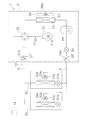
- FIG. 1 is a schematic configuration diagram of an air conditioner 1 according to an embodiment of the present invention.
- the air conditioner 1 is a device capable of cooling and heating a room such as a building by performing a vapor compression refrigeration cycle.
- the air conditioner 1 mainly includes an outdoor unit 2, indoor units 3a and 3b, a liquid refrigerant communication tube 4 and a gas refrigerant communication tube 5 that connect the outdoor unit 2 and the indoor units 3a and 3b, an outdoor unit 2 and And a control unit 19 that controls the constituent devices of the indoor units 3a and 3b.
- the vapor compression refrigerant circuit 10 of the air conditioner 1 is configured by connecting the outdoor unit 2 and the indoor units 3 a and 3 b via the refrigerant communication tubes 4 and 5.
- the indoor units 3a and 3b are installed indoors or behind the ceiling, and constitute a part of the refrigerant circuit 10. Since the indoor unit 3a and the indoor unit 3b have the same configuration, only the configuration of the indoor unit 3a will be described here.
- the configuration of the indoor unit 3b is a subscript “Subscript “b” is attached instead of “a”, and description of each part is omitted.
- the indoor unit 3a mainly has an indoor expansion valve 31a, an indoor heat exchanger 32a, and an indoor fan 33a.
- the indoor expansion valve 31a is an expansion mechanism that depressurizes the refrigerant, and an electric expansion valve is used here.
- the indoor heat exchanger 32a is a heat exchanger that exchanges heat between the refrigerant exchanged with the outdoor unit 2 through the liquid refrigerant communication tube 4 and the gas refrigerant communication tube 5 and the indoor air.
- the liquid side of the indoor heat exchanger 32 a is connected to the liquid refrigerant communication tube 4, and the gas side of the indoor heat exchanger 32 a is connected to the gas refrigerant communication tube 5.
- the indoor fan 33a is a fan that sends room air to the indoor heat exchanger 32a.
- the indoor fan 33a is driven by an indoor fan motor 34a.
- the outdoor unit 2 is installed outside and constitutes a part of the refrigerant circuit 10.
- the outdoor unit 2 mainly includes a compressor 21, a four-way switching valve 22, an outdoor heat exchanger 23, a receiver 24, an outdoor expansion valve 25, a liquid side closing valve 26, a gas side closing valve 27, And an outdoor fan 28.
- the compressor 21 is a device for compressing a refrigerant.
- a compressor in which a positive displacement compression element (not shown) is rotationally driven by a compressor motor 21a is used.
- the suction side and the discharge side of the compressor 21 are connected to the four-way switching valve 22.
- the four-way switching valve 22 connects the discharge side of the compressor 21 and the gas side of the outdoor heat exchanger 23 when the outdoor heat exchanger 23 functions as a refrigerant radiator (hereinafter referred to as “heat dissipation state”). 1 (see the solid line of the four-way switching valve 22 in FIG. 1), and when the outdoor heat exchanger 23 functions as a refrigerant evaporator (hereinafter referred to as “evaporation state”), the suction side of the compressor 21
- This is a switching mechanism capable of switching the refrigerant flow in the refrigerant circuit 10 so as to connect to the gas side of the outdoor heat exchanger 23 (see the broken line of the four-way switching valve 22 in FIG. 1).
- the outdoor heat exchanger 23 is a heat exchanger that performs heat exchange between the refrigerant exchanged with the indoor unit 3 through the liquid refrigerant communication tube 4 and the gas refrigerant communication tube 5 and outdoor air.
- the liquid side of the outdoor heat exchanger 23 is connected to the receiver 24, and the gas side of the outdoor heat exchanger 23 is connected to the four-way switching valve 22.
- the receiver 24 is a container for temporarily storing the refrigerant exchanged with the indoor unit 3 through the liquid refrigerant communication pipe 4.
- One end side of the receiver 24 is connected to the liquid side of the outdoor heat exchanger 23, and the other end side of the receiver 24 is connected to the outdoor expansion valve 25.
- the outdoor expansion valve 25 is an expansion mechanism that depressurizes the refrigerant, and an electric expansion valve is used here.
- One end side of the outdoor expansion valve 25 is connected to the receiver 24, and the other end side of the outdoor expansion valve 25 is connected to the liquid side closing valve 26.
- the liquid side shut-off valve 26 is a valve mechanism provided at a connection portion between the outdoor unit 2 and the liquid refrigerant communication pipe 4. Here, a manual valve with a service port 26 a used for refrigerant charging or the like is used. Yes.
- One end side of the liquid side closing valve 26 is connected to the outdoor expansion valve 25, and the other end side of the liquid side closing valve 26 is connected to the liquid refrigerant communication tube 4.
- the gas side shut-off valve 27 is a valve mechanism provided at a connection portion between the outdoor unit 2 and the gas refrigerant communication pipe 5, and here, a manual valve with a service port 27a used for refrigerant charging or the like is used. Yes.
- One end side of the gas side closing valve 27 is connected to the four-way switching valve 22, and the other end side of the gas side closing valve 27 is connected to the gas refrigerant communication pipe 5.
- the service ports 26a and 27a only need to be provided in a part of the refrigerant circuit 10 included in the outdoor unit 2, and are not limited to those provided in the closing valves 26 and 27.
- the outdoor fan 28 is a fan that sends outdoor air to the outdoor heat exchanger 23.
- the outdoor fan 28 is driven by an outdoor fan motor 28a.
- the outdoor unit 2 is provided with various sensors. Specifically, the outdoor unit 2 is provided with a discharge pressure sensor 11 that detects a refrigerant pressure Pd on the discharge side of the compressor 21. The outdoor unit 2 is provided with an outdoor heat exchange temperature sensor 12 that detects the temperature Tl of the refrigerant in the outdoor heat exchanger 23.
- the refrigerant communication pipes 4 and 5 are refrigerant pipes that are constructed on site when the air conditioner 1 is installed at an installation location such as a building.
- One end side of the liquid refrigerant communication tube 4 is connected to the liquid side closing valve 26 of the indoor unit 2, and the other end side of the liquid refrigerant communication tube 5 is connected to the indoor expansion valves 31a and 31b of the indoor units 3a and 3b.
- One end side of the gas refrigerant communication pipe 5 is connected to the gas side closing valve 27 of the indoor unit 2, and the other end side of the gas refrigerant communication pipe 5 is the gas side of the indoor heat exchangers 32a and 32b of the indoor units 3a and 3b. It is connected to the.
- the control unit 19 is configured by a communication connection of a control board, a remote controller or the like (not shown) provided in the outdoor unit 2 or the indoor units 3a and 3b.
- a control board a remote controller or the like (not shown) provided in the outdoor unit 2 or the indoor units 3a and 3b.
- FIG. 1 for the sake of convenience, the outdoor unit 2 and the indoor units 3a and 3b are illustrated at positions away from each other.
- the control unit 19 controls the components 21, 22, 25, 31a, 31b, 33a, 33b of the air conditioner 1 (here, the outdoor unit 2 and the indoor units 3a, 3b), that is, the operation of the refrigerant circuit 10. Operation control of the whole air conditioning apparatus 1 including it is performed.
- the refrigerant circuit 10 contains a refrigerant containing a fluorinated hydrocarbon having a property of causing a disproportionation reaction.
- a refrigerant there is an ethylene-based fluorinated hydrocarbon (hydrofluoroolefin) having a carbon-carbon double bond that has little influence on the ozone layer and global warming and is easily decomposed by OH radicals.
- hydrofluoroolefins HFO
- HFO hydrofluoroolefins
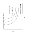
- FIG. 2 is a diagram showing the relationship between the pressure and temperature at which the mixed refrigerant containing the fluorinated hydrocarbon having the property of causing the disproportionation reaction causes the disproportionation reaction.
- the plurality of curves shown in FIG. 2 indicate the boundary between the pressure and temperature at which the mixed refrigerant causes a disproportionation reaction.
- the smaller the composition of the fluorinated hydrocarbon having the property of causing the disproportionation reaction, the higher the curve. Shifted to a high temperature region (upper right side of the figure). In the regions above and above the curves, the refrigerant causes a disproportionation reaction, and in the regions below the curve, the refrigerant does not cause a disproportionation reaction.
- a mixed refrigerant obtained by mixing another refrigerant (a refrigerant not having the property of causing a disproportionation reaction) with a fluorinated hydrocarbon having a property of causing a disproportionation reaction is used.
- a mixed refrigerant of HFO-1123 and another refrigerant is used as a refrigerant containing HFO-1123 as a fluorinated hydrocarbon having a property of causing a disproportionation reaction.
- HFO-1123 and HFC-32 As a mixed refrigerant of HFO-1123 and another refrigerant, there is a mixture of HFO-1123 and HFC-32.
- the composition (wt%) of HFO-1123 and HFC-32 is 40:60.
- HFO-1123 with HFC-134a, HFO-1234yf (2, 3, 3, 3-tetrafluoropropene) and the like there are also mixtures of HFO-1123 with HFC-134a, HFO-1234yf (2, 3, 3, 3-tetrafluoropropene) and the like.
- HFO-1123 has a boiling point different from that of other refrigerants (such as HFC-32)
- such a mixed refrigerant is a non-azeotropic refrigerant mixture in which a low-boiling refrigerant and a high-boiling refrigerant are mixed.
- HFO-1123 since HFO-1123 has a lower boiling point than other refrigerants such as HFC-32, it becomes a non-azeotropic refrigerant mixture using HFO-1123 as a low-boiling refrigerant and other refrigerant as a high-boiling refrigerant.
- the other refrigerant mixed with HFO-1123 is not limited to HFC-32 or the like, and may be any refrigerant that does not have the property of causing a disproportionation reaction. Further, the number of other refrigerants mixed in HFO-1123 is not limited to one but may be two or more.
- the fluorinated hydrocarbon having the property of causing the disproportionation reaction is not limited to HFO-1123, and an ethylene-based or acetylene-based fluorinated hydrocarbon having the property of causing the disproportionation reaction may be used.
- the fluorinated hydrocarbon having the property of causing a disproportionation reaction may be a high boiling point refrigerant having a higher boiling point than other refrigerants.
- Air-conditioning operation In the air conditioning apparatus 1, a cooling operation and a heating operation are performed as the air-conditioning operation.
- the air conditioning operation is performed by the control unit 19.
- the four-way switching valve 22 is switched to the heat dissipation state (the state shown by the solid line in FIG. 1).
- the non-azeotropic refrigerant mixture in the low-pressure gas state of the refrigeration cycle is sucked into the compressor 21 and is compressed until it reaches the high pressure of the refrigeration cycle, and then discharged.
- the high-pressure gas state non-azeotropic mixed refrigerant discharged from the compressor 21 is sent to the outdoor heat exchanger 23 through the four-way switching valve 22.
- the high-pressure gas state non-azeotropic mixed refrigerant sent to the outdoor heat exchanger 23 is supplied to the outdoor heat exchanger 23 functioning as a radiator of the non-azeotropic mixed refrigerant. Heat is exchanged with air to dissipate heat, resulting in a high-pressure liquid non-azeotropic refrigerant mixture.
- the high-pressure liquid non-azeotropic refrigerant mixture that has radiated heat in the outdoor heat exchanger 23 is temporarily stored in the receiver 24, and then passed through the outdoor expansion valve 25, the liquid-side shut-off valve 26, and the liquid refrigerant communication tube 4. It is sent to the expansion valves 31a and 31b.
- the non-azeotropic mixed refrigerant sent to the indoor expansion valves 31a and 31b is decompressed to the low pressure of the refrigeration cycle by the indoor expansion valves 31a and 31b, and becomes a low-pressure gas-liquid two-phase non-azeotropic mixed refrigerant.
- the low-pressure gas-liquid two-phase non-azeotropic mixed refrigerant decompressed by the indoor expansion valves 31a and 31b is sent to the indoor heat exchangers 32a and 32b.
- the low-pressure gas-liquid two-phase non-azeotropic refrigerant mixture sent to the indoor heat exchangers 32a and 32b is mixed with indoor air supplied as a heating source by the indoor fans 33a and 33b in the indoor heat exchangers 32a and 32b.
- the four-way switching valve 22 is switched to the evaporation state (the state indicated by the broken line in FIG. 1).
- the non-azeotropic refrigerant mixture in the low-pressure gas state of the refrigeration cycle is sucked into the compressor 21 and is compressed until it reaches the high pressure of the refrigeration cycle, and then discharged.
- the high-pressure gas state non-azeotropic refrigerant discharged from the compressor 8 is sent to the indoor heat exchangers 32 a and 32 b through the four-way switching valve 22, the gas-side closing valve 27, and the gas refrigerant communication pipe 5.
- the high-pressure gas-state non-azeotropic mixed refrigerant sent to the indoor heat exchangers 32a and 32b exchanges heat with indoor air supplied as a cooling source by the indoor fans 33a and 33b in the indoor heat exchangers 32a and 32b.
- indoor air is heated, and indoor heating is performed by being supplied indoors after that.
- the high-pressure liquid non-azeotropic refrigerant mixture radiated by the indoor heat exchangers 32 a and 32 b is sent to the outdoor expansion valve 25 through the indoor expansion valves 31 a and 31 b, the liquid refrigerant communication pipe 4 and the liquid side closing valve 26.
- the non-azeotropic refrigerant mixture sent to the outdoor expansion valve 25 is decompressed to the low pressure of the refrigeration cycle by the outdoor expansion valve 25 to become a low-pressure gas-liquid two-phase non-azeotropic refrigerant mixture.
- the low-pressure gas-liquid two-phase non-azeotropic refrigerant mixture decompressed by the outdoor expansion valve 25 is temporarily stored in the receiver 24 and then sent to the outdoor heat exchanger 23.
- the low-pressure gas-liquid two-phase non-azeotropic mixed refrigerant sent to the outdoor heat exchanger 23 is supplied as a heating source by the outdoor fan 28 in the outdoor heat exchanger 23 that functions as an evaporator of the non-azeotropic mixed refrigerant.
- the refrigerant is evaporated by exchanging heat with the outdoor air, and becomes a non-azeotropic refrigerant in a low-pressure gas state.
- the low-pressure gas state non-azeotropic mixed refrigerant evaporated in the outdoor heat exchanger 23 is again sucked into the compressor 21 through the four-way switching valve 22.
- a fluorinated hydrocarbon having a property of causing a disproportionation reaction (here, HFO-1123, which is a low boiling point refrigerant) is unevenly distributed in each part of the refrigerant circuit 10. If a non-azeotropic refrigerant mixture leaks in such a state, non-azeotropic mixing is performed in the refrigerant circuit 10 to such an extent that the non-azeotropic refrigerant mixture cannot leak.
- the composition of the fluorinated hydrocarbon having the property of causing a disproportionation reaction in the refrigerant may be increased (see FIG. 2), which may cause a disproportionation reaction.
- the non-azeotropic refrigerant mixture having the desired composition ratio is a refrigerant in the refrigerant circuit 10.
- the composition of the fluorinated hydrocarbon having the property of causing a disproportionation reaction in the non-azeotropic refrigerant mixture may be increased to the extent that the circuit 10 cannot be filled (see FIG. 2). May cause disproportionation reaction. For this reason, it is necessary to suppress the disproportionation reaction even if a non-azeotropic refrigerant mixture leaks or is poorly charged.
- a non-azeotropic refrigerant mixture collected in the outdoor unit 2 is obtained by performing a pump-down operation that collects the non-azeotropic refrigerant mixture in a portion of the refrigerant circuit 10 included in the outdoor unit 2.
- the composition ratio of the non-azeotropic refrigerant mixture is detected based on the pressure and temperature of the gas and the composition ratio of the non-azeotropic refrigerant mixture causes a disproportionation reaction.
- a warning is issued when the composition ratio is out of the range.
- FIG. 3 is a flowchart showing pump down operation and composition ratio detection.
- FIG. 4 is a graph showing the relationship between the saturation temperature and the saturation pressure of a non-azeotropic refrigerant mixture containing a fluorinated hydrocarbon having a property of causing a disproportionation reaction.
- the pump-down operation and composition ratio detection described below are performed by the control unit 19 as in the air-conditioning operation.
- the refrigerant sealed in the refrigerant circuit 10 a two-component system containing a fluorinated hydrocarbon having a property of causing a disproportionation reaction such as a mixed refrigerant of HFO-1123 and HFC-32 as a low boiling point refrigerant.
- a fluorinated hydrocarbon having a property of causing a disproportionation reaction such as a mixed refrigerant of HFO-1123 and HFC-32 as a low boiling point refrigerant.
- a mixed refrigerant of HFO-1123 and HFC-32 as a low boiling point refrigerant.
- step ST1 the control unit 19 determines whether or not a predetermined detection time has elapsed since the previous composition ratio detection (for example, an integrated value of the time during which the air conditioning operation was performed). That is, the control unit 19 periodically performs pump down operation and composition ratio detection. In the case of the first composition ratio detection, it may be determined whether or not the detection time has elapsed after the air conditioner 1 is installed. If the control unit 19 determines in step ST1 that the detection time has elapsed, the control unit 19 proceeds to the next step ST2.
- a predetermined detection time for example, an integrated value of the time during which the air conditioning operation was performed. That is, the control unit 19 periodically performs pump down operation and composition ratio detection.
- the control unit 19 determines in step ST1 that the detection time has elapsed, the control unit 19 proceeds to the next step ST2.
- the controller 19 performs a pump-down operation in step ST2.
- the pump-down operation is an operation for collecting the non-azeotropic refrigerant mixture in the portion of the refrigerant circuit 10 included in the outdoor unit 2, and stops the flow of the refrigerant from the outdoor unit 2 to the indoor units 3a and 3b.
- the refrigerant is caused to flow from the indoor units 3a and 3b to the outdoor unit 2.
- the four-way switching valve 22 is switched to the heat dissipation state (the state indicated by the solid line in FIG. 1), and the outdoor heat exchanger 23 functions as a radiator for the non-azeotropic refrigerant mixture.
- the refrigerant flow from the outdoor unit 2 to the indoor units 3a and 3b is stopped by fully closing the outdoor expansion valve 25.
- the high-pressure gas state non-azeotropic mixed refrigerant discharged from the compressor 21 dissipates heat in the outdoor heat exchanger 23 to become a high-pressure liquid state non-azeotropic mixed refrigerant. Then, it accumulates in the outdoor heat exchanger 23 and the receiver 24 located between the discharge side of the compressor 21 and the outdoor expansion valve 25.
- the non-azeotropic refrigerant mixture existing in the liquid refrigerant communication tube 4, the indoor units 3a and 3b, and the gas refrigerant communication tube 5 is reduced by being sucked into the compressor 21, and the outdoor unit 2 (mainly outdoor heat). Collected in exchanger 23 and receiver 24). And the control part 19 complete
- the pump down operation end condition is that a predetermined time (a time during which the non-azeotropic refrigerant mixture is sufficiently transferred to the outdoor unit 2) has elapsed since the pump down operation was started.
- the pressure or temperature of the non-azeotropic refrigerant mixture in the refrigerant circuit 10 (for example, the refrigerant pressure Pd on the discharge side of the compressor 21) reaches a predetermined value.
- control unit 19 performs composition ratio detection in steps ST3 and ST4, and the composition of the fluorinated hydrocarbon having the property that the composition ratio of the non-azeotropic refrigerant mixture obtained by the composition ratio detection causes a disproportionation reaction. It is determined whether the composition ratio is out of the allowable range.
- the composition ratio detection is processing for obtaining the composition ratio of the non-azeotropic mixed refrigerant based on the pressure and temperature of the non-azeotropic mixed refrigerant collected in the outdoor unit 2 by the pump-down operation as described above.
- the relationship between the saturation temperature and the saturation pressure of a non-azeotropic refrigerant mixture containing a fluorinated hydrocarbon having the property of causing a disproportionation reaction as shown in FIG. 4 is shown for each composition ratio of the non-azeotropic refrigerant mixture.
- FIG. 4 when the composition ratio of the non-azeotropic refrigerant mixture is a normal value, the relationship between the saturation pressure and the saturation temperature (solid line), and the composition ratio of the non-azeotropic refrigerant mixture is within the allowable range for the disproportionation reaction.
- the relationship (broken line) between the saturation pressure and the saturation temperature in the case of the upper limit value is shown.
- the composition ratio of the non-azeotropic mixed refrigerant is obtained from the pressure and temperature of the non-azeotropic mixed refrigerant collected in the outdoor unit 2.
- the saturation pressure and saturation temperature of the non-azeotropic refrigerant mixture are the pressure Pd of the non-azeotropic refrigerant mixture on the discharge side of the compressor 21.
- the control unit 19 obtains the composition ratio of the non-azeotropic refrigerant mixture by applying these pressure Pd and temperature Tl to the relational expression and data table of the saturation temperature and saturation pressure of the non-azeotropic refrigerant mixture. Then, the control unit 19 determines whether or not the composition ratio of the non-azeotropic refrigerant mixture obtained by the composition ratio detection is out of the allowable range of the composition of the fluorinated hydrocarbon having the property of causing a disproportionation reaction. Determine. Specifically, it is determined whether or not the composition ratio of the non-azeotropic refrigerant mixture obtained by the composition ratio detection exceeds the broken line in FIG.
- the composition ratio of the non-azeotropic refrigerant mixture obtained by the composition ratio detection is the point A corresponding to the pressure Pa and the temperature Ta
- the solid line in FIG. 4 (the normal value of the composition ratio of the non-azeotropic refrigerant mixture).
- the composition ratio of the non-azeotropic refrigerant mixture obtained by the composition ratio detection is a point B corresponding to the pressure Pb and the temperature Ta
- composition ratio of the non-azeotropic refrigerant mixture obtained by the composition ratio detection is a point C corresponding to the pressure Pc and the temperature Ta, it is at a position exceeding the broken line in FIG. Leakage or filling failure has occurred and is outside the allowable range.
- composition ratio of the non-azeotropic refrigerant mixture obtained by the composition ratio detection is a composition ratio that is outside the allowable range of the composition of the fluorinated hydrocarbon having the property of causing a disproportionation reaction. Then, it is determined that there is a possibility of causing a disproportionation reaction, and the process proceeds to the next step ST5.
- the composition ratio of the non-azeotropic refrigerant mixture obtained by the composition ratio detection is a composition ratio within the allowable range of the composition of the fluorinated hydrocarbon having the property of causing a disproportionation reaction
- the process returns to step ST1 to continue the operation of the air conditioner 1 (air conditioning operation).
- the composition of the fluorinated hydrocarbon having the property of causing the disproportionation reaction contained in the non-azeotropic refrigerant mixture due to the leakage or poor filling of the non-azeotropic refrigerant mixture is out of the allowable range. It is checked whether it is not.
- step ST5 the control unit 19 issues a warning that the non-azeotropic refrigerant mixture has a composition ratio that may cause a disproportionation reaction. And the control part 19 stops the driving
- the warning may be displayed on the air conditioner 1, or may be notified to the service center or the like when the air conditioner 1 is network-connected to the service center or the like. .
- the non-azeotropic refrigerant mixture is collected in the outdoor unit 2 by the pump-down operation.
- the pump-down operation almost all of the non-azeotropic refrigerant mixture containing the fluorinated hydrocarbon having the property of causing the disproportionation reaction unevenly distributed in each part of the refrigerant circuit 10 is collected in the outdoor unit 2 and then performed.
- a state suitable for composition ratio detection can be obtained.
- composition ratio detection is performed to obtain the composition ratio of the non-azeotropic refrigerant mixture based on the pressure Pd and the temperature Tl of the non-azeotropic refrigerant refrigerant collected in the outdoor unit 2 by the pump-down operation.
- composition ratio of the non-azeotropic refrigerant mixture obtained by the composition ratio detection is a composition ratio outside the allowable range of the composition of the fluorinated hydrocarbon having the property of causing a disproportionation reaction. Therefore, it is determined that there is a possibility of causing a disproportionation reaction, a warning is issued, and the operation of the air conditioner 1 can be stopped.
- the composition ratio of the non-azeotropic refrigerant mixture obtained by the composition ratio detection is within the allowable range of the composition of the fluorinated hydrocarbon having the property of causing the disproportionation reaction, the disproportionation reaction is performed.
- the operation of the air conditioner 1 can be continued by determining that there is no risk of waking up.
- the composition of the fluorinated hydrocarbon having the property of causing a disproportionation reaction contained in the non-azeotropic refrigerant mixture due to leakage or poor filling of the non-azeotropic refrigerant mixture is out of the allowable range. You can check for it.
- the non-azeotropic refrigerant mixture containing the fluorinated hydrocarbon having the property of causing the disproportionation reaction in the refrigerant circuit 10 is enclosed, the non-azeotropic refrigerant mixture is leaked or poorly filled. Even if it occurs, it is possible to suppress the disproportionation reaction.
- the pump-down operation is an operation for collecting the non-azeotropic refrigerant mixture in the outdoor heat exchanger 23 and the receiver 24, a large amount of the non-azeotropic refrigerant mixture is collected in a high-pressure liquid state. As a result, the accuracy of the composition ratio detection can be improved.
- the accurate non-azeotropic refrigerant pressure Pd on the discharge side of the compressor 21 and the temperature Tl of the non-azeotropic refrigerant mixture in the outdoor heat exchanger 23 are used.
- the composition ratio of the boiling mixed refrigerant can be obtained.
- the temperature Tl of the non-azeotropic refrigerant mixture in the outdoor heat exchanger 23 is used as the temperature of the non-azeotropic refrigerant mixture used in the composition ratio detection.
- the present invention is not limited to this. .
- the receiver 24 is provided with a receiver temperature sensor 13 that detects the temperature of the non-azeotropic refrigerant mixture in the receiver 24, and the temperature Tl of the non-azeotropic refrigerant mixture detected by the receiver temperature sensor 13. May be used as the temperature of the non-azeotropic refrigerant mixture used in composition ratio detection.
- the receiver 24 may be provided with a sampling port 29 for extracting the non-azeotropic refrigerant mixture.
- the sampling port 29 is provided with a sampling valve 29a that is manually opened and closed.
- the composition ratio of the non-azeotropic refrigerant mixture is analyzed in detail as necessary. Can do.
- the composition ratio of the non-azeotropic refrigerant mixture is determined to be within the allowable range for the disproportionation reaction by detecting the composition ratio, but the upper limit of the allowable range for the disproportionation reaction (see FIG. 4).
- a non-azeotropic refrigerant mixture can be extracted from the sampling port 29 and a detailed composition ratio analysis can be performed.
- the refrigerant circuit 10 is filled with the non-azeotropic refrigerant mixture containing a large amount of low-boiling refrigerant. It will shift. In order to prevent such a filling failure, it is preferable to fill the refrigerant circuit 10 in a liquid state with a non-azeotropic refrigerant mixture from a cylinder.
- a siphon tube 6a for taking out the liquid non-azeotropic refrigerant mixture from the vicinity of the bottom of the cylinder 6
- the refrigerant circuit 10 is filled with a non-azeotropic refrigerant mixture through the service port of the outdoor unit 2 (using the service port 26a in FIG. 7).
- the cylinder 6 may be turned upside down to fill the refrigerant circuit 10 with the non-azeotropic refrigerant mixture.
- the refrigerant circuit 10 can be filled with a non-azeotropic refrigerant mixture having a normal composition ratio.
- the outdoor unit 2 is not charged with the non-azeotropic mixed refrigerant in the gas state
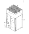
- warning information indicating that the non-azeotropic refrigerant mixture is not charged in the gas state or the non-azeotropic refrigerant mixture is charged in the liquid state is displayed on the outer surface of the outdoor unit 2.
- the label 2a is provided.
- the label 2a in the vicinity of the service ports 26a and 27a used for charging the refrigerant in order to urge the operator to be alerted.
- the model of the outdoor unit 2 is limited to this.
- the label 2a may be provided on another type of outdoor unit 2.
- the present invention is applied by taking the cooling / heating switching type air conditioner 1 capable of switching between the cooling operation and the heating operation as an example.
- the air conditioner to which the present invention can be applied is not limited to this, and the present invention can also be applied to an air conditioner capable of only cooling or an air conditioner capable of simultaneous cooling and heating.
- the indoor multi-type air conditioner 1 in which a plurality of indoor units 3a and 3b are connected to the outdoor unit 2 has been described as an example.
- the present invention is not limited to this.
- a pair type air conditioner in which one indoor unit is connected to the outdoor unit 2 may be used.
- the present invention is widely applicable to an air conditioner in which a non-azeotropic refrigerant mixture containing a fluorinated hydrocarbon having a property of causing a disproportionation reaction in a refrigerant circuit is enclosed.
Landscapes
- Engineering & Computer Science (AREA)
- Physics & Mathematics (AREA)
- Mechanical Engineering (AREA)
- Thermal Sciences (AREA)
- General Engineering & Computer Science (AREA)
- Compression-Type Refrigeration Machines With Reversible Cycles (AREA)
- Air Conditioning Control Device (AREA)
Abstract
冷媒回路(10)の動作を制御する制御部(19)は、冷媒回路(10)のうち室外ユニット(2)に含まれる部分に非共沸混合冷媒を集めるポンプダウン運転を行い、ポンプダウン運転によって室外ユニット(2)に集められた非共沸混合冷媒の圧力及び温度に基づいて非共沸混合冷媒の組成比を得る組成比検知を行い、組成比検知によって得られた非共沸混合冷媒の組成比が不均化反応を起こす性質のフッ化炭化水素の組成の許容範囲を外れた組成比である場合に警告を発報する。
Description
本発明は、空気調和装置に関する。
従来より、空気調和装置の冷媒回路に封入される冷媒として、オゾン層の破壊を防止するために、HFC-32(ジフルオロメタン)や、HFC-32及びHFC-125(ペンタフルオロエタン)の混合物からなるHFC-410A、HFC-134a(1、1、1、2-テトラフルオロエタン)、等が使用されている。しかし、これらの冷媒は、GWP(地球温暖化係数)が大きいという問題がある。
これに対して、特許文献1(国際公開第2012/157764号)に示されるように、HFO-1123(1、1、2-トリフルオロエチレン)が、オゾン層及び地球温暖化に対する影響が少ないことが知られている。そして、特許文献1では、HFO-1123にHFC-32等を混合した混合冷媒を冷媒回路に封入して空気調和装置を構成することが示されている。
HFO-1123は、高圧、高温の条件下で何らかのエネルギーが付与されると、不均化反応(自己分解反応)を起こす性質を有している。そして、冷媒回路内でHFO-1123が不均化反応を起こすと、急激な圧力上昇や急激な温度上昇が発生し、これにより、冷媒回路を構成する機器や配管が損傷して、冷媒や反応生成物が冷媒回路外に放出されるおそれがある。このため、不均化反応を起こす性質のフッ化炭化水素を冷媒として冷媒回路に封入して空気調和装置を構成する場合には、不均化反応を起こしにくくする必要がある。これに対して、不均化反応を起こす性質のフッ化炭化水素に他の冷媒を混合した混合冷媒を使用すれば、混合冷媒中における不均化反応を起こす性質のフッ化炭化水素の組成が小さくなり、不均化反応を起こすおそれを小さくすることができる。
しかし、不均化反応を起こす性質のフッ化炭化水素に混合される冷媒が、不均化反応を起こす性質のフッ化炭化水素と沸点が異なると、不均化反応を起こす性質のフッ化炭化水素と他の冷媒との混合冷媒は、低沸点冷媒と高沸点冷媒とが混合された非共沸混合冷媒となる。このため、非共沸混合冷媒を使用した空気調和装置では、冷房運転や暖房運転のような空調運転時の放熱や蒸発を伴う非共沸混合冷媒の循環によって、冷媒回路において、低沸点冷媒リッチの組成比になる部分と高沸点冷媒リッチの組成比になる部分とが発生し、その結果、冷媒回路の各部に不均化反応を起こす性質のフッ化炭化水素が偏在することになる。そして、このような状態において非共沸混合冷媒の漏洩が発生した場合には、冷媒回路において、非共沸混合冷媒の漏洩が発生していない状態ではあり得ない程度まで、非共沸混合冷媒中における不均化反応を起こす性質のフッ化炭化水素の組成が大きくなるおそれがあり、これにより、不均化反応を起こすおそれがある。また、充填不良によって冷媒回路に封入された非共沸混合冷媒の組成比が所望の組成比になっていない場合にも、冷媒回路において、所望の組成比の非共沸混合冷媒が冷媒回路に充填されている状態ではあり得ない程度まで、非共沸混合冷媒中における不均化反応を起こす性質のフッ化炭化水素の組成が大きくなるおそれがあり、これにより、不均化反応を起こすおそれがある。
本発明の課題は、冷媒回路に不均化反応を起こす性質のフッ化炭化水素を含む非共沸混合冷媒が封入された空気調和装置において、非共沸混合冷媒の漏洩や充填不良が発生しても、不均化反応を起こすことを抑えることにある。
第1の観点にかかる空気調和装置は、室外ユニットと室内ユニットとが接続されることによって構成された冷媒回路と、冷媒回路の動作を制御する制御部と、を有しており、不均化反応を起こす性質のフッ化炭化水素を含む非共沸混合冷媒が冷媒回路に封入されている。制御部は、冷媒回路のうち室外ユニットに含まれる部分に非共沸混合冷媒を集めるポンプダウン運転を行い、ポンプダウン運転によって室外ユニットに集められた非共沸混合冷媒の圧力及び温度に基づいて非共沸混合冷媒の組成比を得る組成比検知を行い、組成比検知によって得られた非共沸混合冷媒の組成比が不均化反応を起こす性質のフッ化炭化水素の組成の許容範囲を外れた組成比である場合に警告を発報する。
ここでは、上記のように、まず、ポンプダウン運転によって非共沸混合冷媒を室外ユニットに集めるようにしている。ここで、ポンプダウン運転とは、室外ユニットから室内ユニットへの冷媒の流れを止めた状態で室内ユニットから室外ユニットに冷媒を流す運転である。そして、ポンプダウン運転によって、冷媒回路の各部に偏在している不均化反応を起こす性質のフッ化炭化水素を含む非共沸混合冷媒のほぼ全てを室外ユニットに集めて、次に行われる組成比検知に適した状態にすることができる。そして、次に、上記のように、ポンプダウン運転によって室外ユニットに集められた非共沸混合冷媒の圧力及び温度に基づいて非共沸混合冷媒の組成比を得る組成比検知を行うようにしている。ここで、組成比検知は、非共沸混合冷媒の組成比毎に飽和圧力及び飽和温度の関係式やデータテーブルを準備しておき、室外ユニットに集められた非共沸混合冷媒の圧力及び温度から非共沸混合冷媒の組成比を得るものである。そして、上記のように、組成比検知によって得られた非共沸混合冷媒の組成比が不均化反応を起こす性質のフッ化炭化水素の組成の許容範囲を外れた組成比である場合には、不均化反応を起こすおそれがあるものと判定して、警告を発報し、空気調和装置の運転を停止することができる。ここで、警告は、空気調和装置に表示するものであってもよいし、空気調和装置がサービスセンタ等にネットワーク接続されている場合には、サービスセンタ等に知らせるものであってもよい。一方、組成比検知によって得られた非共沸混合冷媒の組成比が不均化反応を起こす性質のフッ化炭化水素の組成の許容範囲内の組成比である場合には、不均化反応を起こすおそれがないものと判定して、空気調和装置の運転を継続することができる。このように、ここでは、非共沸混合冷媒の漏洩や充填不良によって非共沸混合冷媒に含まれる不均化反応を起こす性質のフッ化炭化水素の組成が許容範囲を外れた状態になっていないかどうかをチェックすることができる。
これにより、ここでは、冷媒回路に不均化反応を起こす性質のフッ化炭化水素を含む非共沸混合冷媒が封入された空気調和装置において、非共沸混合冷媒の漏洩や充填不良が発生しても、不均化反応を起こすことを抑えることができる。
第2の観点にかかる空気調和装置は、第1の観点にかかる空気調和装置において、制御部が、ポンプダウン運転及び組成比検知を定期的に行う。
ここでは、上記のように、ポンプダウン運転及び組成比検知を定期的に行うようにしているため、不均化反応に対する信頼性を向上させることができる。
第3の観点にかかる空気調和装置は、第1又は第2の観点にかかる空気調和装置において、室外ユニットが、圧縮機、室外熱交換器及びレシーバを有しており、ポンプダウン運転は、室外熱交換器及びレシーバに非共沸混合冷媒を集める運転である。
ここでは、上記のように、ポンプダウン運転が室外熱交換器及びレシーバに非共沸混合冷媒を集める運転であるため、高圧の液状態で大量の非共沸混合冷媒を集めることができ、これにより、組成比検知の精度を向上させることができる。
第4の観点にかかる空気調和装置は、第3の観点にかかる空気調和装置において、組成比検知が、圧縮機の吐出側における非共沸混合冷媒の圧力、及び、室外熱交換器又はレシーバにおける非共沸混合冷媒の温度に基づいて、非共沸混合冷媒の組成比を得る。
ここでは、ポンプダウン運転によって非共沸混合冷媒が高圧の飽和液状態で集められるため、非共沸混合冷媒の飽和圧力及び飽和温度は、圧縮機の吐出側における非共沸混合冷媒の圧力、及び、室外熱交換器又はレシーバにおける非共沸混合冷媒の温度に近い値である。このため、ここでは、上記のように、圧縮機の吐出側における非共沸混合冷媒の圧力、及び、室外熱交換器又はレシーバにおける非共沸混合冷媒の温度に基づいて、正確な非共沸混合冷媒の組成比を得ることができる。
第5の観点にかかる空気調和装置は、第3又は第4の観点にかかる空気調和装置において、レシーバが、非共沸混合冷媒を抽出するためのサンプリングポートを有している。
ここでは、上記のように、レシーバが非共沸混合冷媒を抽出するためのサンプリングポートを有しているため、必要に応じて、非共沸混合冷媒の組成比を詳細に分析することができる。
第6の観点にかかる空気調和装置は、第1~第5の観点のいずれかにかかる空気調和装置において、非共沸混合冷媒が、HFO-1123を含んでいる。
HFO-1123は、不均化反応を起こす性質のフッ化炭化水素の一種であり、沸点がHFC-32等の他の冷媒よりも低い。このため、HFO-1123を含む非共沸混合冷媒では、HFO-1123が低沸点冷媒となって、冷媒回路の各部に偏在することになる。
しかし、ここでは、上記のポンプダウン運転によって、冷媒回路の各部に偏在するHFO-1123を含む非共沸混合冷媒のほぼ全てを室外ユニットに集めることができ、そして、上記の組成比検知によって、HFO-1123を含む非共沸混合冷媒の組成比を得ることができる。
これにより、ここでは、冷媒回路に不均化反応を起こす性質のフッ化炭化水素としてHFO-1123を含む非共沸混合冷媒が封入された空気調和装置において、非共沸混合冷媒の漏洩や充填不良が発生しても、不均化反応を起こすことを抑えることができる。
以下、本発明にかかる空気調和装置の実施形態について、図面に基づいて説明する。尚、本発明にかかる空気調和装置の実施形態の具体的な構成は、下記の実施形態及びその変形例に限られるものではなく、発明の要旨を逸脱しない範囲で変更可能である。
(1)構成
図1は、本発明の一実施形態にかかる空気調和装置1の概略構成図である。
図1は、本発明の一実施形態にかかる空気調和装置1の概略構成図である。
<全体>
空気調和装置1は、蒸気圧縮式の冷凍サイクルを行うことによって、建物等の室内の冷房及び暖房を行うことが可能な装置である。空気調和装置1は、主として、室外ユニット2と、室内ユニット3a、3bと、室外ユニット2と室内ユニット3a、3bとを接続する液冷媒連絡管4及びガス冷媒連絡管5と、室外ユニット2及び室内ユニット3a、3bの構成機器を制御する制御部19と、を有している。そして、空気調和装置1の蒸気圧縮式の冷媒回路10は、室外ユニット2と、室内ユニット3a、3bとが冷媒連絡管4、5を介して接続されることによって構成されている。
空気調和装置1は、蒸気圧縮式の冷凍サイクルを行うことによって、建物等の室内の冷房及び暖房を行うことが可能な装置である。空気調和装置1は、主として、室外ユニット2と、室内ユニット3a、3bと、室外ユニット2と室内ユニット3a、3bとを接続する液冷媒連絡管4及びガス冷媒連絡管5と、室外ユニット2及び室内ユニット3a、3bの構成機器を制御する制御部19と、を有している。そして、空気調和装置1の蒸気圧縮式の冷媒回路10は、室外ユニット2と、室内ユニット3a、3bとが冷媒連絡管4、5を介して接続されることによって構成されている。
<室内ユニット>
室内ユニット3a、3bは、室内や天井裏に設置されており、冷媒回路10の一部を構成している。尚、室内ユニット3aと室内ユニット3bとは同様の構成であるため、ここでは、室内ユニット3aの構成のみ説明し、室内ユニット3bの構成については、それぞれ、室内ユニット3aの各部を示す添え字「a」の代わりに添え字「b」を付して、各部の説明を省略する。室内ユニット3aは、主として、室内膨張弁31aと、室内熱交換器32aと、室内ファン33aと、を有している。
室内ユニット3a、3bは、室内や天井裏に設置されており、冷媒回路10の一部を構成している。尚、室内ユニット3aと室内ユニット3bとは同様の構成であるため、ここでは、室内ユニット3aの構成のみ説明し、室内ユニット3bの構成については、それぞれ、室内ユニット3aの各部を示す添え字「a」の代わりに添え字「b」を付して、各部の説明を省略する。室内ユニット3aは、主として、室内膨張弁31aと、室内熱交換器32aと、室内ファン33aと、を有している。
室内膨張弁31aは、冷媒の減圧を行う膨張機構であり、ここでは、電動膨張弁が使用されている。
室内熱交換器32aは、液冷媒連絡管4及びガス冷媒連絡管5を通じて室外ユニット2とやりとりされる冷媒と室内空気との熱交換を行う熱交換器である。室内熱交換器32aの液側は、液冷媒連絡管4に接続されており、室内熱交換器32aのガス側は、ガス冷媒連絡管5に接続されている。
室内ファン33aは、室内空気を室内熱交換器32aに送るファンである。室内ファン33aは、室内ファン用モータ34aによって駆動される。
<室外ユニット>
室外ユニット2は、室外に設置されており、冷媒回路10の一部を構成している。室外ユニット2は、主として、圧縮機21と、四路切換弁22と、室外熱交換器23と、レシーバ24と、室外膨張弁25と、液側閉鎖弁26と、ガス側閉鎖弁27と、室外ファン28と、を有している。
室外ユニット2は、室外に設置されており、冷媒回路10の一部を構成している。室外ユニット2は、主として、圧縮機21と、四路切換弁22と、室外熱交換器23と、レシーバ24と、室外膨張弁25と、液側閉鎖弁26と、ガス側閉鎖弁27と、室外ファン28と、を有している。
圧縮機21は、冷媒を圧縮するための機器であり、例えば、容積式の圧縮要素(図示せず)が圧縮機用モータ21aによって回転駆動される圧縮機が使用されている。圧縮機21の吸入側及び吐出側は、四路切換弁22に接続されている。
四路切換弁22は、室外熱交換器23を冷媒の放熱器として機能させる場合(以下、「放熱状態」とする)には圧縮機21の吐出側と室外熱交換器23のガス側とを接続し(図1の四路切換弁22の実線を参照)、室外熱交換器23を冷媒の蒸発器として機能させる場合(以下、「蒸発状態」とする)には圧縮機21の吸入側と室外熱交換器23のガス側とを接続するように(図1の四路切換弁22の破線を参照)、冷媒回路10内における冷媒の流れを切り換えることが可能な切換機構である。
室外熱交換器23は、液冷媒連絡管4及びガス冷媒連絡管5を通じて室内ユニット3とやりとりされる冷媒と室外空気との熱交換を行う熱交換器である。室外熱交換器23の液側は、レシーバ24に接続されており、室外熱交換器23のガス側は、四路切換弁22に接続されている。
レシーバ24は、液冷媒連絡管4を通じて室内ユニット3とやりとりされる冷媒を一時的に溜めるための容器である。レシーバ24の一端側は、室外熱交換器23の液側に接続されており、レシーバ24の他端側は、室外膨張弁25に接続されている。
室外膨張弁25は、冷媒の減圧を行う膨張機構であり、ここでは、電動膨張弁が使用されている。室外膨張弁25の一端側は、レシーバ24に接続されており、室外膨張弁25の他端側は、液側閉鎖弁26に接続されている。
液側閉鎖弁26は、室外ユニット2と液冷媒連絡管4との接続部に設けられた弁機構であり、ここでは、冷媒充填等に使用されるサービスポート26a付きの手動弁が使用されている。液側閉鎖弁26の一端側は、室外膨張弁25に接続されており、液側閉鎖弁26の他端側は、液冷媒連絡管4に接続されている。ガス側閉鎖弁27は、室外ユニット2とガス冷媒連絡管5との接続部に設けられた弁機構であり、ここでは、冷媒充填等に使用されるサービスポート27a付きの手動弁が使用されている。ガス側閉鎖弁27の一端側は、四路切換弁22に接続されており、ガス側閉鎖弁27の他端側は、ガス冷媒連絡管5に接続されている。尚、サービスポート26a、27aは、冷媒回路10のうち室外ユニット2に含まれる部分に設けられていればよく、閉鎖弁26、27に設けられたものに限定されない。
室外ファン28は、室外空気を室外熱交換器23に送るファンである。室外ファン28は、室外ファン用モータ28aによって駆動される。
室外ユニット2には、各種のセンサが設けられている。具体的には、室外ユニット2には、圧縮機21の吐出側における冷媒の圧力Pdを検出する吐出圧力センサ11が設けられている。また、室外ユニット2には、室外熱交換器23における冷媒の温度Tlを検出する室外熱交温度センサ12と、が設けられている。
<冷媒連絡管>
冷媒連絡管4、5は、空気調和装置1を建物等の設置場所に設置する際に、現地にて施工される冷媒管である。液冷媒連絡管4の一端側は、室内ユニット2の液側閉鎖弁26に接続され、液冷媒連絡管5の他端側は、室内ユニット3a、3bの室内膨張弁31a、31bに接続されている。ガス冷媒連絡管5の一端側は、室内ユニット2のガス側閉鎖弁27に接続され、ガス冷媒連絡管5の他端側は、室内ユニット3a、3bの室内熱交換器32a、32bのガス側に接続されている。
冷媒連絡管4、5は、空気調和装置1を建物等の設置場所に設置する際に、現地にて施工される冷媒管である。液冷媒連絡管4の一端側は、室内ユニット2の液側閉鎖弁26に接続され、液冷媒連絡管5の他端側は、室内ユニット3a、3bの室内膨張弁31a、31bに接続されている。ガス冷媒連絡管5の一端側は、室内ユニット2のガス側閉鎖弁27に接続され、ガス冷媒連絡管5の他端側は、室内ユニット3a、3bの室内熱交換器32a、32bのガス側に接続されている。
<制御部>
制御部19は、室外ユニット2や室内ユニット3a、3bに設けられた制御基板やリモコン等(図示せず)が通信接続されることによって構成されている。尚、図1においては、便宜上、室外ユニット2や室内ユニット3a、3bとは離れた位置に図示している。制御部19は、空気調和装置1(ここでは、室外ユニット2や室内ユニット3a、3b)の構成機器21、22、25、31a、31b、33a、33bの制御、すなわち、冷媒回路10の動作を含む空気調和装置1全体の運転制御を行うようになっている。
制御部19は、室外ユニット2や室内ユニット3a、3bに設けられた制御基板やリモコン等(図示せず)が通信接続されることによって構成されている。尚、図1においては、便宜上、室外ユニット2や室内ユニット3a、3bとは離れた位置に図示している。制御部19は、空気調和装置1(ここでは、室外ユニット2や室内ユニット3a、3b)の構成機器21、22、25、31a、31b、33a、33bの制御、すなわち、冷媒回路10の動作を含む空気調和装置1全体の運転制御を行うようになっている。
<冷媒回路に封入される冷媒>
冷媒回路10には、不均化反応を起こす性質のフッ化炭化水素を含む冷媒が封入されている。このような冷媒として、オゾン層及び地球温暖化への影響がともに少なく、OHラジカルによって分解されやすい炭素-炭素二重結合を有するエチレン系のフッ化炭化水素(ヒドロフルオロオレフィン)がある。そして、ここでは、ヒドロフルオロオレフィン(HFO)の中でも、優れた性能を有するHFO-1123を含む冷媒が採用されている。
冷媒回路10には、不均化反応を起こす性質のフッ化炭化水素を含む冷媒が封入されている。このような冷媒として、オゾン層及び地球温暖化への影響がともに少なく、OHラジカルによって分解されやすい炭素-炭素二重結合を有するエチレン系のフッ化炭化水素(ヒドロフルオロオレフィン)がある。そして、ここでは、ヒドロフルオロオレフィン(HFO)の中でも、優れた性能を有するHFO-1123を含む冷媒が採用されている。
しかし、冷媒回路内でHFO-1123が不均化反応を起こすと、急激な圧力上昇や急激な温度上昇が発生し、これにより、冷媒回路10を構成する機器や配管が損傷して、HFO-1123を含む冷媒や反応生成物が冷媒回路10外に放出されるおそれがある。
このため、HFO-1123のような不均化反応を起こす性質のフッ化炭化水素を冷媒として冷媒回路10に封入する場合には、不均化反応を起こしにくくする必要がある。これに対して、不均化反応を起こす性質のフッ化炭化水素に他の冷媒を混合した混合冷媒を使用すれば、混合冷媒中における不均化反応を起こす性質のフッ化炭化水素の組成が小さくなり、不均化反応を起こすおそれを小さくすることができる。ここで、図2は、不均化反応を起こす性質のフッ化炭化水素を含む混合冷媒が不均化反応を起こす圧力及び温度の関係を示す図である。図2に示される複数の曲線は、混合冷媒が不均化反応を起こす圧力及び温度の境界を示しており、不均化反応を起こす性質のフッ化炭化水素の組成が小さいほど、曲線が高圧、高温の領域(図の右上側)にシフトしている。そして、これら曲線上及び上側の領域では冷媒が不均化反応を起こし、曲線よりも下側の領域では冷媒が不均化反応を起こさないことを示している。すなわち、上記のように、不均化反応を起こす性質のフッ化炭化水素に他の冷媒(不均化反応を起こす性質を有しない冷媒)を混合した混合冷媒を使用し、不均化反応を起こす性質のフッ化炭化水素の組成を小さくすることによって、不均化反応を起こすおそれを小さくすることができるのである。ここでは、不均化反応を起こす性質のフッ化炭化水素としてのHFO-1123を含む冷媒として、HFO-1123と他の冷媒との混合冷媒が使用される。そして、HFO-1123と他の冷媒との混合冷媒としては、HFO-1123とHFC-32との混合物がある。ここで、HFO-1123とHFC-32の組成(wt%)は、40:60である。また、HFO-1123とHFC-134aやHFO-1234yf(2、3、3、3-テトラフルオロプロペン)等との混合物もある。ここで、HFO-1123は、他の冷媒(HFC-32等)と沸点が異なるため、このような混合冷媒は、低沸点冷媒と高沸点冷媒とが混合された非共沸混合冷媒となる。また、HFO-1123は、HFC-32等の他の冷媒よりも沸点が低いため、HFO-1123を低沸点冷媒とし、かつ、他の冷媒を高沸点冷媒とする非共沸混合冷媒となる。尚、HFO-1123に混合される他の冷媒としては、HFC-32等に限定されるものではなく、不均化反応を起こす性質を有しない冷媒であればよい。また、HFO-1123に混合される他の冷媒は、1つだけでなく2つ以上であってもよい。また、不均化反応を起こす性質のフッ化炭化水素としては、HFO-1123に限定されるものではなく、不均化反応を起こす性質のエチレン系やアセチレン系のフッ化炭化水素であってもよく、この場合に、不均化反応を起こす性質のフッ化炭化水素が他の冷媒よりも沸点が高い高沸点冷媒であってもよい。
(2)空調運転
空気調和装置1では、空調運転として、冷房運転及び暖房運転が行われる。尚、空調運転は、制御部19によって行われる。
空気調和装置1では、空調運転として、冷房運転及び暖房運転が行われる。尚、空調運転は、制御部19によって行われる。
<冷房運転>
冷房運転時には、四路切換弁22が放熱状態(図1の実線で示される状態)に切り換えられる。冷媒回路10において、冷凍サイクルの低圧のガス状態の非共沸混合冷媒は、圧縮機21に吸入され、冷凍サイクルの高圧になるまで圧縮された後に吐出される。圧縮機21から吐出された高圧のガス状態の非共沸混合冷媒は、四路切換弁22を通じて、室外熱交換器23に送られる。室外熱交換器23に送られた高圧のガス状態の非共沸混合冷媒は、非共沸混合冷媒の放熱器として機能する室外熱交換器23において、室外ファン28によって冷却源として供給される室外空気と熱交換を行って放熱して、高圧の液状態の非共沸混合冷媒になる。室外熱交換器23において放熱した高圧の液状態の非共沸混合冷媒は、レシーバ24に一時的に溜められた後に、室外膨張弁25、液側閉鎖弁26及び液冷媒連絡管4を通じて、室内膨張弁31a、31bに送られる。室内膨張弁31a、31bに送られた非共沸混合冷媒は、室内膨張弁31a、31bによって冷凍サイクルの低圧まで減圧されて、低圧の気液二相状態の非共沸混合冷媒になる。室内膨張弁31a、31bで減圧された低圧の気液二相状態の非共沸混合冷媒は、室内熱交換器32a、32bに送られる。室内熱交換器32a、32bに送られた低圧の気液二相状態の非共沸混合冷媒は、室内熱交換器32a、32bにおいて、室内ファン33a、33bによって加熱源として供給される室内空気と熱交換を行って蒸発する。これにより、室内空気は冷却され、その後に、室内に供給されることで室内の冷房が行われる。室内熱交換器32a、32bにおいて蒸発した低圧のガス状態の非共沸混合冷媒は、ガス冷媒連絡管5、ガス側閉鎖弁27及び四路切換弁22を通じて、再び、圧縮機21に吸入される。
冷房運転時には、四路切換弁22が放熱状態(図1の実線で示される状態)に切り換えられる。冷媒回路10において、冷凍サイクルの低圧のガス状態の非共沸混合冷媒は、圧縮機21に吸入され、冷凍サイクルの高圧になるまで圧縮された後に吐出される。圧縮機21から吐出された高圧のガス状態の非共沸混合冷媒は、四路切換弁22を通じて、室外熱交換器23に送られる。室外熱交換器23に送られた高圧のガス状態の非共沸混合冷媒は、非共沸混合冷媒の放熱器として機能する室外熱交換器23において、室外ファン28によって冷却源として供給される室外空気と熱交換を行って放熱して、高圧の液状態の非共沸混合冷媒になる。室外熱交換器23において放熱した高圧の液状態の非共沸混合冷媒は、レシーバ24に一時的に溜められた後に、室外膨張弁25、液側閉鎖弁26及び液冷媒連絡管4を通じて、室内膨張弁31a、31bに送られる。室内膨張弁31a、31bに送られた非共沸混合冷媒は、室内膨張弁31a、31bによって冷凍サイクルの低圧まで減圧されて、低圧の気液二相状態の非共沸混合冷媒になる。室内膨張弁31a、31bで減圧された低圧の気液二相状態の非共沸混合冷媒は、室内熱交換器32a、32bに送られる。室内熱交換器32a、32bに送られた低圧の気液二相状態の非共沸混合冷媒は、室内熱交換器32a、32bにおいて、室内ファン33a、33bによって加熱源として供給される室内空気と熱交換を行って蒸発する。これにより、室内空気は冷却され、その後に、室内に供給されることで室内の冷房が行われる。室内熱交換器32a、32bにおいて蒸発した低圧のガス状態の非共沸混合冷媒は、ガス冷媒連絡管5、ガス側閉鎖弁27及び四路切換弁22を通じて、再び、圧縮機21に吸入される。
<暖房運転>
暖房運転時には、四路切換弁22が蒸発状態(図1の破線で示される状態)に切り換えられる。冷媒回路10において、冷凍サイクルの低圧のガス状態の非共沸混合冷媒は、圧縮機21に吸入され、冷凍サイクルの高圧になるまで圧縮された後に吐出される。圧縮機8から吐出された高圧のガス状態の非共沸混合冷媒は、四路切換弁22、ガス側閉鎖弁27及びガス冷媒連絡管5を通じて、室内熱交換器32a、32bに送られる。室内熱交換器32a、32bに送られた高圧のガス状態の非共沸混合冷媒は、室内熱交換器32a、32bにおいて、室内ファン33a、33bによって冷却源として供給される室内空気と熱交換を行って放熱して、高圧の液状態の非共沸混合冷媒になる。これにより、室内空気は加熱され、その後に、室内に供給されることで室内の暖房が行われる。室内熱交換器32a、32bで放熱した高圧の液状態の非共沸混合冷媒は、室内膨張弁31a、31b、液冷媒連絡管4及び液側閉鎖弁26を通じて、室外膨張弁25に送られる。室外膨張弁25に送られた非共沸混合冷媒は、室外膨張弁25によって冷凍サイクルの低圧まで減圧されて、低圧の気液二相状態の非共沸混合冷媒になる。室外膨張弁25で減圧された低圧の気液二相状態の非共沸混合冷媒は、レシーバ24に一時的に溜められた後に、室外熱交換器23に送られる。室外熱交換器23に送られた低圧の気液二相状態の非共沸混合冷媒は、非共沸混合冷媒の蒸発器として機能する室外熱交換器23において、室外ファン28によって加熱源として供給される室外空気と熱交換を行って蒸発して、低圧のガス状態の非共沸混合冷媒になる。室外熱交換器23で蒸発した低圧のガス状態の非共沸混合冷媒は、四路切換弁22を通じて、再び、圧縮機21に吸入される。
暖房運転時には、四路切換弁22が蒸発状態(図1の破線で示される状態)に切り換えられる。冷媒回路10において、冷凍サイクルの低圧のガス状態の非共沸混合冷媒は、圧縮機21に吸入され、冷凍サイクルの高圧になるまで圧縮された後に吐出される。圧縮機8から吐出された高圧のガス状態の非共沸混合冷媒は、四路切換弁22、ガス側閉鎖弁27及びガス冷媒連絡管5を通じて、室内熱交換器32a、32bに送られる。室内熱交換器32a、32bに送られた高圧のガス状態の非共沸混合冷媒は、室内熱交換器32a、32bにおいて、室内ファン33a、33bによって冷却源として供給される室内空気と熱交換を行って放熱して、高圧の液状態の非共沸混合冷媒になる。これにより、室内空気は加熱され、その後に、室内に供給されることで室内の暖房が行われる。室内熱交換器32a、32bで放熱した高圧の液状態の非共沸混合冷媒は、室内膨張弁31a、31b、液冷媒連絡管4及び液側閉鎖弁26を通じて、室外膨張弁25に送られる。室外膨張弁25に送られた非共沸混合冷媒は、室外膨張弁25によって冷凍サイクルの低圧まで減圧されて、低圧の気液二相状態の非共沸混合冷媒になる。室外膨張弁25で減圧された低圧の気液二相状態の非共沸混合冷媒は、レシーバ24に一時的に溜められた後に、室外熱交換器23に送られる。室外熱交換器23に送られた低圧の気液二相状態の非共沸混合冷媒は、非共沸混合冷媒の蒸発器として機能する室外熱交換器23において、室外ファン28によって加熱源として供給される室外空気と熱交換を行って蒸発して、低圧のガス状態の非共沸混合冷媒になる。室外熱交換器23で蒸発した低圧のガス状態の非共沸混合冷媒は、四路切換弁22を通じて、再び、圧縮機21に吸入される。
(3)冷媒の不均化反応への対策(非共沸混合冷媒の組成比の検知)
不均化反応を起こす性質のフッ化炭化水素(ここでは、HFO-1123)を含む非共沸混合冷媒が冷媒回路10に封入された空気調和装置1では、冷房運転や暖房運転のような空調運転時の放熱や蒸発を伴う非共沸混合冷媒の循環によって、冷媒回路10において、低沸点冷媒(ここでは、HFO-1123)リッチの組成比になる部分と高沸点冷媒(ここでは、HFC―32等)リッチの組成比になる部分とが発生する。このため、冷媒回路10の各部には、不均化反応を起こす性質のフッ化炭化水素(ここでは、低沸点冷媒であるHFO-1123)が偏在することになる。そして、このような状態において非共沸混合冷媒の漏洩が発生した場合には、冷媒回路10において、非共沸混合冷媒の漏洩が発生していない状態ではあり得ない程度まで、非共沸混合冷媒中における不均化反応を起こす性質のフッ化炭化水素の組成が大きくなるおそれがあり(図2参照)、これにより、不均化反応を起こすおそれがある。また、充填不良によって冷媒回路10に封入された非共沸混合冷媒の組成比が所望の組成比になっていない場合にも、冷媒回路10において、所望の組成比の非共沸混合冷媒が冷媒回路10に充填されている状態ではあり得ない程度まで、非共沸混合冷媒中における不均化反応を起こす性質のフッ化炭化水素の組成が大きくなるおそれがあり(図2参照)、これにより、不均化反応を起こすおそれがある。このため、非共沸混合冷媒の漏洩や充填不良が発生しても、不均化反応を起こすことを抑える必要がある。
不均化反応を起こす性質のフッ化炭化水素(ここでは、HFO-1123)を含む非共沸混合冷媒が冷媒回路10に封入された空気調和装置1では、冷房運転や暖房運転のような空調運転時の放熱や蒸発を伴う非共沸混合冷媒の循環によって、冷媒回路10において、低沸点冷媒(ここでは、HFO-1123)リッチの組成比になる部分と高沸点冷媒(ここでは、HFC―32等)リッチの組成比になる部分とが発生する。このため、冷媒回路10の各部には、不均化反応を起こす性質のフッ化炭化水素(ここでは、低沸点冷媒であるHFO-1123)が偏在することになる。そして、このような状態において非共沸混合冷媒の漏洩が発生した場合には、冷媒回路10において、非共沸混合冷媒の漏洩が発生していない状態ではあり得ない程度まで、非共沸混合冷媒中における不均化反応を起こす性質のフッ化炭化水素の組成が大きくなるおそれがあり(図2参照)、これにより、不均化反応を起こすおそれがある。また、充填不良によって冷媒回路10に封入された非共沸混合冷媒の組成比が所望の組成比になっていない場合にも、冷媒回路10において、所望の組成比の非共沸混合冷媒が冷媒回路10に充填されている状態ではあり得ない程度まで、非共沸混合冷媒中における不均化反応を起こす性質のフッ化炭化水素の組成が大きくなるおそれがあり(図2参照)、これにより、不均化反応を起こすおそれがある。このため、非共沸混合冷媒の漏洩や充填不良が発生しても、不均化反応を起こすことを抑える必要がある。
そこで、ここでは、以下に説明するように、冷媒回路10のうち室外ユニット2に含まれる部分に非共沸混合冷媒を集めるポンプダウン運転を行い、室外ユニット2に集められた非共沸混合冷媒の圧力及び温度に基づいて非共沸混合冷媒の組成比を得る組成比検知を行い、非共沸混合冷媒の組成比が不均化反応を起こす性質のフッ化炭化水素の組成の許容範囲を外れた組成比である場合に警告を発報するようにしている。
<ポンプダウン運転及び組成比検知>
次に、ポンプダウン運転及び組成比検知について、図1~図4を用いて説明する。ここで、図3は、ポンプダウン運転及び組成比検知を示すフローチャートである。図4は、不均化反応を起こす性質のフッ化炭化水素を含む非共沸混合冷媒の飽和温度と飽和圧力の関係を示す図である。尚、以下に説明するポンプダウン運転及び組成比検知は、空調運転と同様に、制御部19によって行われる。また、ここでは、冷媒回路10に封入される冷媒として、HFO-1123とHFC-32との混合冷媒のような不均化反応を起こす性質のフッ化炭化水素を低沸点冷媒として含む2成分系の非共沸混合冷媒を採用した場合を例に挙げて説明する。
次に、ポンプダウン運転及び組成比検知について、図1~図4を用いて説明する。ここで、図3は、ポンプダウン運転及び組成比検知を示すフローチャートである。図4は、不均化反応を起こす性質のフッ化炭化水素を含む非共沸混合冷媒の飽和温度と飽和圧力の関係を示す図である。尚、以下に説明するポンプダウン運転及び組成比検知は、空調運転と同様に、制御部19によって行われる。また、ここでは、冷媒回路10に封入される冷媒として、HFO-1123とHFC-32との混合冷媒のような不均化反応を起こす性質のフッ化炭化水素を低沸点冷媒として含む2成分系の非共沸混合冷媒を採用した場合を例に挙げて説明する。
まず、制御部19は、ステップST1において、前回の組成比検知からの時間(例えば、空調運転を行った時間の積算値等)が所定の検知時間を経過したかどうかを判定する。すなわち、制御部19は、ポンプダウン運転及び組成比検知を定期的に行う。尚、初回の組成比検知である場合には、空気調和装置1の設置後に検知時間を経過したかどうかを判定すればよい。そして、制御部19は、ステップST1において、検知時間を経過したと判定した場合には、次のステップST2の処理に移行する。
次に、制御部19は、ステップST2において、ポンプダウン運転を行う。ポンプダウン運転は、上記のように、冷媒回路10のうち室外ユニット2に含まれる部分に非共沸混合冷媒を集める運転であり、室外ユニット2から室内ユニット3a、3bへの冷媒の流れを止めた状態で室内ユニット3a、3bから室外ユニット2に冷媒を流すことによって行われる。具体的には、冷房運転時と同様に、四路切換弁22を放熱状態(図1の実線で示される状態)に切り換えて、室外熱交換器23を非共沸混合冷媒の放熱器として機能させる。但し、冷房運転時とは異なり、室外膨張弁25を全閉状態にすることによって、室外ユニット2から室内ユニット3a、3bへの冷媒の流れを止めた状態にする。この場合、冷房運転時と同様、圧縮機21から吐出された高圧のガス状態の非共沸混合冷媒は、室外熱交換器23において放熱して、高圧の液状態の非共沸混合冷媒になり、圧縮機21の吐出側と室外膨張弁25との間に位置する室外熱交換器23及びレシーバ24に溜まる。一方で、液冷媒連絡管4、室内ユニット3a、3b及びガス冷媒連絡管5に存在する非共沸混合冷媒は、圧縮機21に吸入されることによって減少し、室外ユニット2(主として、室外熱交換器23及びレシーバ24)に集められる。そして、制御部19は、ステップST2において、ポンプダウン運転終了条件が成立した場合に、ポンプダウン運転を終了して、次のステップST3の処理に移行する。ここで、ポンプダウン運転終了条件としては、ポンプダウン運転が開始されてから所定時間(非共沸混合冷媒の室外ユニット2への移動が十分に行われたものとみなすことができる時間)が経過した場合、及び/又は、冷媒回路10における非共沸混合冷媒の圧力や温度(例えば、圧縮機21の吐出側における冷媒の圧力Pd)が所定値に達した場合等が挙げられる。このポンプダウン運転によって、冷媒回路10の各部に偏在している不均化反応を起こす性質のフッ化炭化水素を含む非共沸混合冷媒のほぼ全てを室外ユニット2に集めて、続いて行われる組成比検知に適した状態にしている。
次に、制御部19は、ステップST3、ST4において、組成比検知を行い、組成比検知によって得られた非共沸混合冷媒の組成比が不均化反応を起こす性質のフッ化炭化水素の組成の許容範囲を外れた組成比であるかどうかを判定する。組成比検知は、上記のように、ポンプダウン運転によって室外ユニット2に集められた非共沸混合冷媒の圧力及び温度に基づいて非共沸混合冷媒の組成比を得る処理である。具体的には、図4に示すような不均化反応を起こす性質のフッ化炭化水素を含む非共沸混合冷媒の飽和温度と飽和圧力の関係を、非共沸混合冷媒の組成比毎に飽和圧力及び飽和温度の関係式やデータテーブルとして準備しておく。図4においては、非共沸混合冷媒の組成比が正常値である場合の飽和圧力及び飽和温度の関係(実線)、及び、非共沸混合冷媒の組成比が不均化反応に対する許容範囲の上限値である場合の飽和圧力及び飽和温度の関係(破線)を示している。そして、室外ユニット2に集められた非共沸混合冷媒の圧力及び温度から非共沸混合冷媒の組成比を得る。ここでは、ポンプダウンによって非共沸混合冷媒が高圧の飽和液状態で集められるため、非共沸混合冷媒の飽和圧力及び飽和温度は、圧縮機21の吐出側における非共沸混合冷媒の圧力Pd、及び、室外熱交換器23における非共沸混合冷媒の温度Tlに近い値である。そして、制御部19は、これらの圧力Pd及び温度Tlを非共沸混合冷媒の飽和温度と飽和圧力の関係式やデータテーブルに当てはめることによって、非共沸混合冷媒の組成比を得る。そして、制御部19は、組成比検知によって得られた非共沸混合冷媒の組成比が、不均化反応を起こす性質のフッ化炭化水素の組成の許容範囲を外れた組成比であるかどうかを判定する。具体的には、組成比検知によって得られた非共沸混合冷媒の組成比が、図4の破線(すなわち、不均化反応に対する許容範囲の上限値)を超えているかどうかを判定する。例えば、組成比検知によって得られた非共沸混合冷媒の組成比が圧力Pa及び温度Taに対応する点Aである場合には、図4の実線(非共沸混合冷媒の組成比の正常値)上の位置にあり、非共沸混合冷媒の漏洩や充填不良が発生しておらず正常である。また、組成比検知によって得られた非共沸混合冷媒の組成比が圧力Pb及び温度Taに対応する点Bである場合には、図4の実線と破線(不均化反応に対する許容範囲の上限値)との間の位置にあり、非共沸混合冷媒の漏洩や充填不良が発生しているが許容範囲内である。また、組成比検知によって得られた非共沸混合冷媒の組成比が圧力Pc及び温度Taに対応する点Cである場合には、図4の破線を超える位置にあり、非共沸混合冷媒の漏洩や充填不良が発生し許容範囲から外れている。そして、制御部19は、組成比検知によって得られた非共沸混合冷媒の組成比が不均化反応を起こす性質のフッ化炭化水素の組成の許容範囲を外れた組成比である場合には、不均化反応を起こすおそれがあるものと判定して、次のステップST5の処理に移行する。一方、制御部19は、組成比検知によって得られた非共沸混合冷媒の組成比が不均化反応を起こす性質のフッ化炭化水素の組成の許容範囲内の組成比である場合には、不均化反応を起こすおそれがないものと判定して、ステップST1の処理に戻り、空気調和装置1の運転(空調運転)を継続する。この組成比検知を含む処理によって、非共沸混合冷媒の漏洩や充填不良によって非共沸混合冷媒に含まれる不均化反応を起こす性質のフッ化炭化水素の組成が許容範囲を外れた状態になっていないかどうかがチェックされる。
次に、制御部19は、ステップST5において、非共沸混合冷媒が不均化反応を起こすおそれがある組成比になっている旨の警告を発報する。そして、制御部19は、空気調和装置1の運転を停止する。ここで、警告は、空気調和装置1に表示するものであってもよいし、空気調和装置1がサービスセンタ等にネットワーク接続されている場合には、サービスセンタ等に知らせるものであってもよい。
<特徴>
上記のように、本実施形態では、まず、ポンプダウン運転によって非共沸混合冷媒を室外ユニット2に集めるようにしている。このポンプダウン運転によって、冷媒回路10の各部に偏在している不均化反応を起こす性質のフッ化炭化水素を含む非共沸混合冷媒のほぼ全てを室外ユニット2に集めて、次に行われる組成比検知に適した状態にすることができる。そして、次に、上記のように、ポンプダウン運転によって室外ユニット2に集められた非共沸混合冷媒の圧力Pd及び温度Tlに基づいて非共沸混合冷媒の組成比を得る組成比検知を行うようにしている。そして、上記のように、組成比検知によって得られた非共沸混合冷媒の組成比が不均化反応を起こす性質のフッ化炭化水素の組成の許容範囲を外れた組成比である場合には、不均化反応を起こすおそれがあるものと判定して、警告を発報し、空気調和装置1の運転を停止することができる。一方、組成比検知によって得られた非共沸混合冷媒の組成比が不均化反応を起こす性質のフッ化炭化水素の組成の許容範囲内の組成比である場合には、不均化反応を起こすおそれがないものと判定して、空気調和装置1の運転を継続することができる。このように、ここでは、非共沸混合冷媒の漏洩や充填不良によって非共沸混合冷媒に含まれる不均化反応を起こす性質のフッ化炭化水素の組成が許容範囲を外れた状態になっていないかどうかをチェックすることができる。
上記のように、本実施形態では、まず、ポンプダウン運転によって非共沸混合冷媒を室外ユニット2に集めるようにしている。このポンプダウン運転によって、冷媒回路10の各部に偏在している不均化反応を起こす性質のフッ化炭化水素を含む非共沸混合冷媒のほぼ全てを室外ユニット2に集めて、次に行われる組成比検知に適した状態にすることができる。そして、次に、上記のように、ポンプダウン運転によって室外ユニット2に集められた非共沸混合冷媒の圧力Pd及び温度Tlに基づいて非共沸混合冷媒の組成比を得る組成比検知を行うようにしている。そして、上記のように、組成比検知によって得られた非共沸混合冷媒の組成比が不均化反応を起こす性質のフッ化炭化水素の組成の許容範囲を外れた組成比である場合には、不均化反応を起こすおそれがあるものと判定して、警告を発報し、空気調和装置1の運転を停止することができる。一方、組成比検知によって得られた非共沸混合冷媒の組成比が不均化反応を起こす性質のフッ化炭化水素の組成の許容範囲内の組成比である場合には、不均化反応を起こすおそれがないものと判定して、空気調和装置1の運転を継続することができる。このように、ここでは、非共沸混合冷媒の漏洩や充填不良によって非共沸混合冷媒に含まれる不均化反応を起こす性質のフッ化炭化水素の組成が許容範囲を外れた状態になっていないかどうかをチェックすることができる。
これにより、ここでは、冷媒回路10に不均化反応を起こす性質のフッ化炭化水素を含む非共沸混合冷媒が封入された空気調和装置1において、非共沸混合冷媒の漏洩や充填不良が発生しても、不均化反応を起こすことを抑えることができる。
また、ここでは、上記のように、ポンプダウン運転及び組成比検知を定期的に行うようにしているため、不均化反応に対する信頼性を向上させることができる。
また、ここでは、上記のように、ポンプダウン運転が室外熱交換器23及びレシーバ24に非共沸混合冷媒を集める運転であるため、高圧の液状態で大量の非共沸混合冷媒を集めることができ、これにより、組成比検知の精度を向上させることができる。
また、ここでは、上記のように、圧縮機21の吐出側における非共沸混合冷媒の圧力Pd、及び、室外熱交換器23における非共沸混合冷媒の温度Tlに基づいて、正確な非共沸混合冷媒の組成比を得ることができる。
(4)変形例1
上記実施形態では、組成比検知において使用される非共沸混合冷媒の温度として、室外熱交換器23における非共沸混合冷媒の温度Tlを使用しているが、これに限定されるものではない。
上記実施形態では、組成比検知において使用される非共沸混合冷媒の温度として、室外熱交換器23における非共沸混合冷媒の温度Tlを使用しているが、これに限定されるものではない。
例えば、図5に示すように、レシーバ24にレシーバ24における非共沸混合冷媒の温度を検出するレシーバ温度センサ13を設けて、このレシーバ温度センサ13によって検出される非共沸混合冷媒の温度Tlを組成比検知において使用される非共沸混合冷媒の温度として使用してもよい。
この場合においても、上記実施形態と同様の作用効果を得ることができる。
(5)変形例2
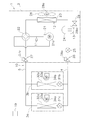
上記実施形態及び変形例1の構成(図1及び図5参照)において、図6に示すように、レシーバ24に非共沸混合冷媒を抽出するためのサンプリングポート29を設けるようにしてもよい。ここで、サンプリングポート29には、手動で開閉されるサンプリング弁29aが設けられている。
上記実施形態及び変形例1の構成(図1及び図5参照)において、図6に示すように、レシーバ24に非共沸混合冷媒を抽出するためのサンプリングポート29を設けるようにしてもよい。ここで、サンプリングポート29には、手動で開閉されるサンプリング弁29aが設けられている。
ここでは、上記のように、レシーバ24が非共沸混合冷媒を抽出するためのサンプリングポート29を有しているため、必要に応じて、非共沸混合冷媒の組成比を詳細に分析することができる。例えば、組成比検知によって非共沸混合冷媒の組成比が不均化反応に対する許容範囲内であるものと判定されたが、その組成比が不均化反応に対する許容範囲の上限値(図4の破線)に非常に近い場合には、サンプリングポート29から非共沸混合冷媒を抽出して、詳細な組成比分析を行うことができる。
(6)変形例3
上記実施形態及び変形例1、2では、充填不良によって非共沸混合冷媒に含まれる不均化反応を起こす性質のフッ化炭化水素の組成が許容範囲を外れた状態になっていないかどうかを組成比検知によってチェックするようにしている。
上記実施形態及び変形例1、2では、充填不良によって非共沸混合冷媒に含まれる不均化反応を起こす性質のフッ化炭化水素の組成が許容範囲を外れた状態になっていないかどうかを組成比検知によってチェックするようにしている。
ここで、このような充填不良は、ボンベから非共沸混合冷媒を冷媒回路10に充填する際に、ガス状態で充填することによって起こることが多い。なぜなら、ボンベ内には、正常な組成比の非共沸混合冷媒が入っているが、ボンベの上部には、低沸点冷媒を多く含むガス状態の非共沸混合冷媒が存在しているからである。すなわち、ボンベから非共沸混合冷媒をガス状態で冷媒回路10に充填すると、冷媒回路10には、低沸点冷媒を多く含む非共沸混合冷媒が充填されることになり、正常な組成比からずれてしまうのである。このような充填不良を防ぐためには、ボンベから非共沸混合冷媒を液状態で冷媒回路10に充填することが好ましい。
そこで、ここでは、図7に示すように、正常な組成比の非共沸混合冷媒が入ったボンベ6として、ボンベ6の底部付近から液状態の非共沸混合冷媒を取り出すためのサイフォン管6aを有するものを準備し、室外ユニット2のサービスポート(図7では、サービスポート26aを使用)を通じて冷媒回路10に非共沸混合冷媒を充填するようにしている。ここで、ボンベ6がサイフォン管6aを有しないものである場合には、ボンベ6を上下逆さまにして冷媒回路10に非共沸混合冷媒を充填するようにしてもよい。これにより、冷媒回路10に正常な組成比の非共沸混合冷媒を充填することができる。
また、ボンベ6から非共沸混合冷媒を液状態で冷媒回路10に充填する作業を作業者に確実に行わせるために、室外ユニット2に、非共沸混合冷媒をガス状態で充填しない旨、又は、非共沸混合冷媒を液状態で充填する旨の警告情報が表示されたラベルを設けることが好ましい。例えば、図8に示すように、室外ユニット2の外表面に、非共沸混合冷媒をガス状態で充填しない旨、又は、非共沸混合冷媒を液状態で充填する旨の警告情報が表示されたラベル2aを設けるのである。このとき、作業者への注意喚起を促すために、ラベル2aを冷媒充填に使用されるサービスポート26a、27a付近に設けることが好ましい。尚、ここでは、室外熱交換器23の上側に室外ファン28が配置された型式の室外ユニット2にラベル2aを設けた例を挙げて説明しているが、室外ユニット2の型式はこれに限定されるものではなく、他の型式の室外ユニット2にラベル2aを設けてもよい。
(7)他の変形例
上記実施形態及び変形例1~3では、冷房運転及び暖房運転を切り換えて行うことが可能な冷暖切替式の空気調和装置1を例に挙げて、本発明を適用した例を説明したが、本発明を適用可能な空気調和装置はこれに限定されるものではなく、冷房のみが可能な空気調和装置や冷暖同時運転可能な空気調和装置にも適用可能である。また、上記実施形態及び変形例1~3では、室外ユニット2に複数の室内ユニット3a、3bが接続された室内マルチ式の空気調和装置1を例に挙げたが、これに限定されるものではなく、室外ユニット2に1つの室内ユニットが接続されたペア式の空気調和装置であってもよい。
上記実施形態及び変形例1~3では、冷房運転及び暖房運転を切り換えて行うことが可能な冷暖切替式の空気調和装置1を例に挙げて、本発明を適用した例を説明したが、本発明を適用可能な空気調和装置はこれに限定されるものではなく、冷房のみが可能な空気調和装置や冷暖同時運転可能な空気調和装置にも適用可能である。また、上記実施形態及び変形例1~3では、室外ユニット2に複数の室内ユニット3a、3bが接続された室内マルチ式の空気調和装置1を例に挙げたが、これに限定されるものではなく、室外ユニット2に1つの室内ユニットが接続されたペア式の空気調和装置であってもよい。
本発明は、冷媒回路に不均化反応を起こす性質のフッ化炭化水素を含む非共沸混合冷媒が封入された空気調和装置に対して、広く適用可能である。
1 空気調和装置
2 室外ユニット
3a、3b 室内ユニット
10 冷媒回路
19 制御部
21 圧縮機
23 室外熱交換器
24 レシーバ
29 サンプリングポート
2 室外ユニット
3a、3b 室内ユニット
10 冷媒回路
19 制御部
21 圧縮機
23 室外熱交換器
24 レシーバ
29 サンプリングポート
Claims (6)
- 室外ユニット(2)と室内ユニット(3a、3b)とが接続されることによって構成された冷媒回路(10)と、前記冷媒回路の動作を制御する制御部(19)と、を有しており、不均化反応を起こす性質のフッ化炭化水素を含む非共沸混合冷媒が前記冷媒回路に封入された空気調和装置において、
前記制御部は、前記冷媒回路のうち前記室外ユニットに含まれる部分に前記非共沸混合冷媒を集めるポンプダウン運転を行い、前記ポンプダウン運転によって前記室外ユニットに集められた前記非共沸混合冷媒の圧力及び温度に基づいて前記非共沸混合冷媒の組成比を得る組成比検知を行い、前記組成比検知によって得られた前記非共沸混合冷媒の組成比が前記不均化反応を起こす性質のフッ化炭化水素の組成の許容範囲を外れた組成比である場合に警告を発報する、
空気調和装置(1)。 - 前記制御部は、前記ポンプダウン運転及び前記組成比検知を定期的に行う、
請求項1に記載の空気調和装置。 - 前記室外ユニットは、圧縮機(21)、室外熱交換器(23)及びレシーバ(24)を有しており、
前記ポンプダウン運転は、前記室外熱交換器及び前記レシーバに前記非共沸混合冷媒を集める運転である、
請求項1又は2に記載の空気調和装置。 - 前記組成比検知は、前記圧縮機の吐出側における前記非共沸混合冷媒の圧力、及び、前記室外熱交換器又は前記レシーバにおける前記非共沸混合冷媒の温度に基づいて、前記非共沸混合冷媒の組成比を得る、
請求項3に記載の空気調和装置。 - 前記レシーバは、前記非共沸混合冷媒を抽出するためのサンプリングポート(29)を有している、
請求項3又は4に記載の空気調和装置。 - 前記非共沸混合冷媒は、HFO-1123を含んでいる、
請求項1~5のいずれか1項に記載の空気調和装置。
Priority Applications (3)
| Application Number | Priority Date | Filing Date | Title |
|---|---|---|---|
| CN201880012669.9A CN110446898B (zh) | 2017-03-31 | 2018-03-23 | 空调装置 |
| US16/492,753 US11112154B2 (en) | 2017-03-31 | 2018-03-23 | Air conditioner |
| EP18776250.5A EP3604971A4 (en) | 2017-03-31 | 2018-03-23 | AIR CONDITIONING DEVICE |
Applications Claiming Priority (2)
| Application Number | Priority Date | Filing Date | Title |
|---|---|---|---|
| JP2017-070186 | 2017-03-31 | ||
| JP2017070186A JP6790966B2 (ja) | 2017-03-31 | 2017-03-31 | 空気調和装置 |
Publications (1)
| Publication Number | Publication Date |
|---|---|
| WO2018181065A1 true WO2018181065A1 (ja) | 2018-10-04 |
Family
ID=63675982
Family Applications (1)
| Application Number | Title | Priority Date | Filing Date |
|---|---|---|---|
| PCT/JP2018/011897 WO2018181065A1 (ja) | 2017-03-31 | 2018-03-23 | 空気調和装置 |
Country Status (5)
| Country | Link |
|---|---|
| US (1) | US11112154B2 (ja) |
| EP (1) | EP3604971A4 (ja) |
| JP (1) | JP6790966B2 (ja) |
| CN (1) | CN110446898B (ja) |
| WO (1) | WO2018181065A1 (ja) |
Families Citing this family (3)
| Publication number | Priority date | Publication date | Assignee | Title |
|---|---|---|---|---|
| WO2017163339A1 (ja) * | 2016-03-23 | 2017-09-28 | 三菱電機株式会社 | 空気調和装置 |
| JP2020148389A (ja) * | 2019-03-13 | 2020-09-17 | 株式会社富士通ゼネラル | 空気調和装置 |
| US20220065503A1 (en) * | 2020-09-02 | 2022-03-03 | Lance Nist | Efficient air conditioning in conjunction with pool filtration |
Citations (6)
| Publication number | Priority date | Publication date | Assignee | Title |
|---|---|---|---|---|
| JP2002267232A (ja) * | 2001-03-12 | 2002-09-18 | Hitachi Ltd | 空気調和機のサービスシステム及びサービス提供装置 |
| WO2012157764A1 (ja) | 2011-05-19 | 2012-11-22 | 旭硝子株式会社 | 作動媒体および熱サイクルシステム |
| WO2015114774A1 (ja) * | 2014-01-30 | 2015-08-06 | 三菱電機株式会社 | 冷凍サイクル装置、空気調和装置、及び、冷凍サイクル装置における循環組成の算出方法 |
| WO2015140874A1 (ja) * | 2014-03-17 | 2015-09-24 | 三菱電機株式会社 | 空気調和装置 |
| WO2015140883A1 (ja) * | 2014-03-17 | 2015-09-24 | 三菱電機株式会社 | 空気調和機 |
| WO2015174054A1 (ja) * | 2014-05-12 | 2015-11-19 | パナソニックIpマネジメント株式会社 | 冷凍サイクル装置 |
Family Cites Families (12)
| Publication number | Priority date | Publication date | Assignee | Title |
|---|---|---|---|---|
| US4179894A (en) * | 1977-12-28 | 1979-12-25 | Wylain, Inc. | Dual source heat pump |
| JP3178103B2 (ja) * | 1992-08-31 | 2001-06-18 | 株式会社日立製作所 | 冷凍サイクル |
| WO2004040208A1 (ja) * | 2002-10-30 | 2004-05-13 | Mitsubishi Denki Kabushiki Kaisha | 空気調和装置 |
| US7832222B2 (en) * | 2007-12-07 | 2010-11-16 | Spx Corporation | Background tank fill based on refrigerant composition |
| US9746223B2 (en) * | 2010-09-30 | 2017-08-29 | Mitsubishi Electric Corporation | Air-conditioning apparatus |
| US9524483B2 (en) * | 2011-11-23 | 2016-12-20 | Advanced Aqua Group | Water conversion system |
| US10018389B2 (en) * | 2011-12-22 | 2018-07-10 | Mitsubishi Electric Corporation | Air-conditioning apparatus |
| EP3118540A4 (en) * | 2014-03-14 | 2017-11-01 | Mitsubishi Electric Corporation | Refrigerating device |
| EP3128257B1 (en) * | 2014-03-17 | 2020-04-22 | Mitsubishi Electric Corporation | Method for operating a refrigeration cycle device |
| JP6279069B2 (ja) * | 2014-03-17 | 2018-02-14 | 三菱電機株式会社 | 冷凍サイクル装置 |
| KR101674075B1 (ko) * | 2015-04-25 | 2016-11-09 | 한국표준과학연구원 | 미세 누출이 없는 주름관 정압실린더 |
| US10247455B2 (en) * | 2016-07-13 | 2019-04-02 | Hanon Systems | Condenser receiver drier refrigerant filter |
-
2017
- 2017-03-31 JP JP2017070186A patent/JP6790966B2/ja active Active
-
2018
- 2018-03-23 CN CN201880012669.9A patent/CN110446898B/zh active Active
- 2018-03-23 WO PCT/JP2018/011897 patent/WO2018181065A1/ja active Application Filing
- 2018-03-23 EP EP18776250.5A patent/EP3604971A4/en active Pending
- 2018-03-23 US US16/492,753 patent/US11112154B2/en active Active
Patent Citations (6)
| Publication number | Priority date | Publication date | Assignee | Title |
|---|---|---|---|---|
| JP2002267232A (ja) * | 2001-03-12 | 2002-09-18 | Hitachi Ltd | 空気調和機のサービスシステム及びサービス提供装置 |
| WO2012157764A1 (ja) | 2011-05-19 | 2012-11-22 | 旭硝子株式会社 | 作動媒体および熱サイクルシステム |
| WO2015114774A1 (ja) * | 2014-01-30 | 2015-08-06 | 三菱電機株式会社 | 冷凍サイクル装置、空気調和装置、及び、冷凍サイクル装置における循環組成の算出方法 |
| WO2015140874A1 (ja) * | 2014-03-17 | 2015-09-24 | 三菱電機株式会社 | 空気調和装置 |
| WO2015140883A1 (ja) * | 2014-03-17 | 2015-09-24 | 三菱電機株式会社 | 空気調和機 |
| WO2015174054A1 (ja) * | 2014-05-12 | 2015-11-19 | パナソニックIpマネジメント株式会社 | 冷凍サイクル装置 |
Non-Patent Citations (1)
| Title |
|---|
| See also references of EP3604971A4 |
Also Published As
| Publication number | Publication date |
|---|---|
| JP2018173196A (ja) | 2018-11-08 |
| EP3604971A4 (en) | 2020-12-02 |
| JP6790966B2 (ja) | 2020-11-25 |
| US20200072518A1 (en) | 2020-03-05 |
| CN110446898B (zh) | 2021-05-25 |
| CN110446898A (zh) | 2019-11-12 |
| EP3604971A1 (en) | 2020-02-05 |
| US11112154B2 (en) | 2021-09-07 |
Similar Documents
| Publication | Publication Date | Title |
|---|---|---|
| US20180119998A1 (en) | Refrigeration cycle apparatus | |
| US10539358B2 (en) | Air-conditioning apparatus and refrigerant leakage detection method | |
| EP2306122B1 (en) | Refrigerating cycle apparatus, and air conditioning apparatus | |
| JP6223546B2 (ja) | 冷凍サイクル装置 | |
| JP5780977B2 (ja) | ヒートポンプサイクル装置 | |
| WO2018181065A1 (ja) | 空気調和装置 | |
| WO2018011994A1 (ja) | 空気調和装置 | |
| WO2016059696A1 (ja) | 冷凍サイクル装置 | |
| US10443886B2 (en) | Air-conditioning apparatus having an indication apparatus | |
| EP2921801B1 (en) | Method of part replacement for refrigeration cycle apparatus | |
| WO2022050352A1 (ja) | 冷媒としての使用、および、冷凍サイクル装置 | |
| WO2018139589A1 (ja) | 冷凍装置 | |
| JP2018173196A5 (ja) | ||
| JP2015215111A (ja) | ヒートポンプ機器 | |
| WO2020090759A1 (ja) | 冷凍サイクル装置 | |
| JP2020094698A (ja) | 冷凍装置 | |
| US20170074561A1 (en) | Refrigeration cycle device | |
| JP6715961B2 (ja) | 冷凍サイクル装置 | |
| WO2012137260A1 (ja) | 冷凍サイクル装置の冷媒回収方法及び冷凍サイクル装置 | |
| JP2020029965A (ja) | 冷凍サイクル装置 | |
| AU2014345151B2 (en) | Refrigeration cycle apparatus, method of manufacturing the same, and method of installing the same | |
| JP6915294B2 (ja) | 冷凍装置の室外機 | |
| JP2015152290A (ja) | 空気調和装置 |
Legal Events
| Date | Code | Title | Description |
|---|---|---|---|
| 121 | Ep: the epo has been informed by wipo that ep was designated in this application |
Ref document number: 18776250 Country of ref document: EP Kind code of ref document: A1 |
|
| NENP | Non-entry into the national phase |
Ref country code: DE |
|
| WWE | Wipo information: entry into national phase |
Ref document number: 2018776250 Country of ref document: EP |
|
| ENP | Entry into the national phase |
Ref document number: 2018776250 Country of ref document: EP Effective date: 20191031 |