WO2018180886A1 - 流体制御機器及びセンサ保持部材 - Google Patents
流体制御機器及びセンサ保持部材 Download PDFInfo
- Publication number
- WO2018180886A1 WO2018180886A1 PCT/JP2018/011394 JP2018011394W WO2018180886A1 WO 2018180886 A1 WO2018180886 A1 WO 2018180886A1 JP 2018011394 W JP2018011394 W JP 2018011394W WO 2018180886 A1 WO2018180886 A1 WO 2018180886A1
- Authority
- WO
- WIPO (PCT)
- Prior art keywords
- fluid control
- control device
- temperature sensor
- hole
- holding member
- Prior art date
- Legal status (The legal status is an assumption and is not a legal conclusion. Google has not performed a legal analysis and makes no representation as to the accuracy of the status listed.)
- Ceased
Links
Images




Classifications
-
- G—PHYSICS
- G01—MEASURING; TESTING
- G01K—MEASURING TEMPERATURE; MEASURING QUANTITY OF HEAT; THERMALLY-SENSITIVE ELEMENTS NOT OTHERWISE PROVIDED FOR
- G01K13/00—Thermometers specially adapted for specific purposes
- G01K13/02—Thermometers specially adapted for specific purposes for measuring temperature of moving fluids or granular materials capable of flow
- G01K13/026—Thermometers specially adapted for specific purposes for measuring temperature of moving fluids or granular materials capable of flow of moving liquids
-
- F—MECHANICAL ENGINEERING; LIGHTING; HEATING; WEAPONS; BLASTING
- F16—ENGINEERING ELEMENTS AND UNITS; GENERAL MEASURES FOR PRODUCING AND MAINTAINING EFFECTIVE FUNCTIONING OF MACHINES OR INSTALLATIONS; THERMAL INSULATION IN GENERAL
- F16K—VALVES; TAPS; COCKS; ACTUATING-FLOATS; DEVICES FOR VENTING OR AERATING
- F16K37/00—Special means in or on valves or other cut-off apparatus for indicating or recording operation thereof, or for enabling an alarm to be given
-
- F—MECHANICAL ENGINEERING; LIGHTING; HEATING; WEAPONS; BLASTING
- F16—ENGINEERING ELEMENTS AND UNITS; GENERAL MEASURES FOR PRODUCING AND MAINTAINING EFFECTIVE FUNCTIONING OF MACHINES OR INSTALLATIONS; THERMAL INSULATION IN GENERAL
- F16K—VALVES; TAPS; COCKS; ACTUATING-FLOATS; DEVICES FOR VENTING OR AERATING
- F16K27/00—Construction of housing; Use of materials therefor
-
- F—MECHANICAL ENGINEERING; LIGHTING; HEATING; WEAPONS; BLASTING
- F16—ENGINEERING ELEMENTS AND UNITS; GENERAL MEASURES FOR PRODUCING AND MAINTAINING EFFECTIVE FUNCTIONING OF MACHINES OR INSTALLATIONS; THERMAL INSULATION IN GENERAL
- F16K—VALVES; TAPS; COCKS; ACTUATING-FLOATS; DEVICES FOR VENTING OR AERATING
- F16K37/00—Special means in or on valves or other cut-off apparatus for indicating or recording operation thereof, or for enabling an alarm to be given
- F16K37/0025—Electrical or magnetic means
-
- G—PHYSICS
- G01—MEASURING; TESTING
- G01K—MEASURING TEMPERATURE; MEASURING QUANTITY OF HEAT; THERMALLY-SENSITIVE ELEMENTS NOT OTHERWISE PROVIDED FOR
- G01K1/00—Details of thermometers not specially adapted for particular types of thermometer
- G01K1/14—Supports; Fastening devices; Arrangements for mounting thermometers in particular locations
-
- G—PHYSICS
- G01—MEASURING; TESTING
- G01K—MEASURING TEMPERATURE; MEASURING QUANTITY OF HEAT; THERMALLY-SENSITIVE ELEMENTS NOT OTHERWISE PROVIDED FOR
- G01K7/00—Measuring temperature based on the use of electric or magnetic elements directly sensitive to heat ; Power supply therefor, e.g. using thermoelectric elements
- G01K7/02—Measuring temperature based on the use of electric or magnetic elements directly sensitive to heat ; Power supply therefor, e.g. using thermoelectric elements using thermoelectric elements, e.g. thermocouples
- G01K7/04—Measuring temperature based on the use of electric or magnetic elements directly sensitive to heat ; Power supply therefor, e.g. using thermoelectric elements using thermoelectric elements, e.g. thermocouples the object to be measured not forming one of the thermoelectric materials
Definitions
- the present invention relates to a fluid control device that holds a temperature sensor and a sensor holding member that holds the temperature sensor.
- thermocouple T / C
- the leak port provided in the existing fluid control device is used as the temperature sensor insertion port.
- the diameter of the temperature sensor does not necessarily match the diameter of the leak port. For this reason, when the diameter of the temperature sensor is sufficiently smaller than the diameter of the leak port, it is necessary to fix the temperature sensor outside the leak port in order to prevent the temperature sensor from falling off the leak port. On the other hand, even if the leak port diameter is suitable for the temperature sensor diameter and the temperature sensor can be fitted into the leak port, the heat change is severe at the location where the leak port is provided. For this reason, the temperature sensor may fall off due to expansion and contraction.
- the fluid control device can be placed in various orientations, such as flat, vertical, and inverted, and the fluid control device itself vibrates or is affected by vibration from peripheral equipment such as a chamber.
- Fixing the sensor requires certainty that the temperature sensor can maintain thermal contact with the leak port in any orientation. Furthermore, in recent years where thinning of the thin film is required, such as the deposition method called ALD (Atomic Layer Deposition), which forms a thin film at the atomic or molecular thickness, there is a difference in fluid control equipment. Of course, it is necessary to ensure that there is no variation in fixing of each device even when fixing the temperature sensor.
- ALD Atomic Layer Deposition
- Patent Document 1 includes a first fluid control device and a second fluid control device that are adjacent to each other, and a thermal sensor that measures the temperature of the fluid flowing through the fluid passage of the first fluid control device.
- a fluid control apparatus further comprising an annular support member that is mounted on the outer peripheral surface of an actuator cap of one of the first fluid control device and the second fluid control device and supports the thermal sensor Has been proposed.
- an object of the present invention is to provide a fluid control device in which the temperature sensor is firmly fixed and the thermal contact between the temperature sensor and the inner peripheral surface of the leak port is reliably maintained.
- a fluid control device is a fluid control device holding a temperature sensor, the temperature sensor being inserted into a deep hole of the fluid control device, and the deep hole And a sensor holding member that holds the temperature sensor in a state of being inserted into the deep hole, and the sensor holding member is a base portion disposed immediately above the deep hole; And a through hole that is provided in the base portion and through which the temperature sensor is inserted and communicated with the deep hole.
- the base portion has a length that fits in a width in a short direction of the fluid control device. .
- the through hole of the sensor holding member and the deep hole may have a predetermined angle.
- the sensor holding member may be made of a flexible resin material.
- the through hole may be formed with a groove on the periphery in the vicinity of the opening on the side communicating with the opening of the deep hole.
- the through hole may be formed by a peripheral wall that protrudes from the base portion and is thinner than the base portion, in the vicinity of the opening facing the deep hole.
- the deep hole may be a leak port of the fluid control device.
- it may be configured as a fluid control device using the fluid control device.
- a sensor holding member is a member that holds a temperature sensor in a fluid control device, and is provided immediately above the deep hole of the fluid control device, and is disposed immediately above the deep hole. And a through hole that is provided in the base portion and through which the temperature sensor is inserted and communicates with the deep hole, and the base portion is arranged in a short direction of the fluid control device. It consists of a length that fits in the width.
- the temperature sensor is firmly fixed, and the thermal contact between the temperature sensor and the inner peripheral surface of the leak port is reliably maintained.
- FIG. 1 shows a fluid control apparatus 1 including a fluid control device 3 according to the present embodiment.
- the fluid control device 1 is configured by a plurality of gas lines 2 (three lines in FIG. 1) adjacent in the width direction, and each gas line 2 is installed on a base sheet metal.
- gas lines 2 three lines in FIG. 1
- each gas line 2 is installed on a base sheet metal.
- the direction of the member and the like may be referred to as up, down, left, and right depending on the direction in the drawing. Therefore, unless otherwise specified, the designated direction does not limit the direction of the member or the like when the present invention is implemented or used.
- each gas line 2 on the substrate a plurality of fluid control devices 3 connected together via block-shaped joints 5 are arranged in a line together with components such as a mass flow controller 4.
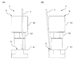
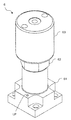
- the fluid control device 3 includes a main body 6, a temperature sensor 7, and a sensor holding member 8.
- the main body 6 includes a valve body 61, an actuator body 62 disposed on the valve body 61, and a casing 63 disposed on the actuator body 62.
- the valve body 61 is provided with a flow path (not shown) through which a fluid flows and a leak port LP that can detect leakage of the fluid.
- the leak port LP is configured as a through hole having a length in the vertical direction of the fluid control device 3.
- One end of the leak port LP communicates with the outside, and the other end is shielded by the block-shaped joint 5 and is separated from the flow path by a sealing member such as a metal gasket. It functions as a deep hole with thickness. Since the leak port LP is provided in the vicinity of the flow path, the temperature can be regarded as the temperature of the fluid by measuring the temperature in the leak port LP.
- the leak port LP is used as a deep hole for inserting the temperature sensor 7.
- the present invention is not limited to this, and the temperature in the fluid or device is measured by inserting the temperature sensor 7. If possible, a dedicated deep hole for measuring the temperature may be provided. Further, the deep hole itself is not limited to the bottomed hole as long as the temperature sensor 7 can be inserted, and may be a through hole.
- the temperature sensor 7 is a thermocouple in this example.
- a thermocouple consists of two types of metal wires. One end of each is electrically connected to form a temperature measuring unit, and the other end is installed at a location of the same reference temperature. The temperature difference between one end and the other end is measured as a voltage from the difference in power.
- One end of the temperature sensor 7 is inserted into the leak port LP and is in contact with the inner peripheral surface of the leak port LP, whereby the temperature in the leak port LP is measured.
- thermocouple is used as the temperature sensor 7, but regardless of this, other temperature measuring instruments can be used as long as they can be inserted into the leak port LP and measured. it can.
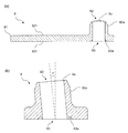
- the sensor holding member 8 is provided immediately above the leak port LP, and holds the temperature sensor 7 in a state of being inserted into the leak port LP. As shown in FIGS. 5 and 6, the sensor holding member 8 has a flat plate-like base portion 81 disposed immediately above the leak port LP, and a substantially cylindrical shape provided on the base portion 81 and open at both ends. The through-hole 8a.
- the sensor holding member 8 is preferably made of a resin material having heat resistance and chemical resistance such as polytetrafluoroethylene (PTFE) and having flexibility.
- PTFE polytetrafluoroethylene
- one surface facing the leak port LP constitutes an upper surface 821, and one surface on the leak port LP side constitutes an attachment surface 831 attached to the valve body 61.
- the sensor holding member 8 is bonded to the smooth surface on the valve body 61 by a heat-resistant adhesive or adhesive tape applied to the mounting surface 831.
- the sensor holding member 8 can be fixed on the valve body 61 with a bolt or the like, or can be detachably engaged by a predetermined engaging means or the like.
- the sensor holding member 8 may be a part of the valve body 61, and the sensor holding member 8 and the valve body 61 may be configured integrally.
- the length of the base portion 81 is a size equal to or smaller than the width of the valve body 61. This is a length that fits within the width of the gas line 2, and therefore the width of the gas line 2 is defined only by the width of the fluid control device 3, and not by the length of the sensor holding member 8.
- the width of the valve body 61 of this example shown in the figure is substantially the same in the length direction and the width direction. However, if the widths in the length direction and the width direction are different, the width in the short direction is set. The size fits.
- the shape of the base portion 81 is substantially rectangular in a plan view in the drawing, but is not limited thereto, and the attachment surface 831 only needs to have a certain area necessary for attachment. Also good.
- the through hole 8a is a hole having a circular cross section, and the temperature sensor 7 is inserted therethrough.
- the through-hole 8a is provided at a position that is eccentric from the center of the base portion 81 and that corresponds to the leak port LP, and communicates with the leak port LP.
- the inner diameter of the through-hole 8a is a diameter that is an interference fit with respect to the outer diameter of the temperature sensor 7, and the temperature sensor 7 is inserted from the opening 82 on the upper surface 821 side into the opening 83 on the mounting surface 831 side. Can be held. This also has the effect of preventing the temperature sensor 7 from falling off even when the fluid control device 1 is used in a state where it is tilted 90 degrees horizontally, for example.
- the through hole 8 a is formed in a direction slightly angled from a direction perpendicular to the mounting surface 831 of the base portion 81.
- an angle is formed in the length direction of the gas line 2 and away from the main body 6. Therefore, as shown in FIG. 7, the through-hole 8a and the leak port LP form a predetermined angle ⁇ in the length direction.
- the temperature sensor 7 inserted into the through hole 8a and inserted into the leak port LP is in contact with the inner peripheral surface of the through hole 8a and the leak port LP, and the portion where the through hole 8a and the leak port LP communicate with each other.
- FIG. 6 (b) the through hole 8 a is formed in a direction slightly angled from a direction perpendicular to the mounting surface 831 of the base portion 81.
- an angle is formed in the length direction of the gas line 2 and away from the main body 6. Therefore, as shown in FIG. 7, the through-hole 8a and the leak port LP form a predetermined angle ⁇ in the length direction.
- the temperature sensor 7 comes into contact with the inner peripheral surface of the leak port LP with a restoring force. As a result, the state in which the temperature sensor 7 is in thermal contact with the inner peripheral surface of the leak port LP is easily maintained.
- the predetermined angle ⁇ is about 5 degrees in the present embodiment, but the standard will be described below. From the condition that the temperature sensor 7 contacts the inner peripheral surface of the leak port LP, the difference between the outer diameter of the temperature sensor 7 and the inner diameter of the leak port LP is ⁇ D, and the depth at which the temperature sensor 7 is inserted into the leak port LP is L.
- ⁇ D the difference between the outer diameter of the temperature sensor 7 and the inner diameter of the leak port LP
- L the depth at which the temperature sensor 7 is inserted into the leak port LP.
- the temperature sensor 7 needs to be close to a direction perpendicular to the mounting surface 831, and a value of about ⁇ ⁇ 10 [°] is desirable. If the angle ⁇ is within this range, the allowable bending R of the thermocouple used as the temperature sensor 7 can be satisfied.
- the through hole 8 a is formed in the vicinity of the opening 82 by a peripheral wall 82 a protruding from the upper surface 821 of the base body 81.
- the peripheral wall 82a is formed thinner than the portion where the through hole 8a is formed by the base portion 81, and the vicinity of the end of the peripheral wall 82a is gradually thinner toward the side facing the base portion 81. .
- annular groove 83a is formed in the periphery of the opening 83 in the through hole 8a.
- the concave groove 83a is gradually narrower toward the groove bottom (slightly wider toward the mounting surface 831 side).
- the through hole 8a and the leak port LP form a predetermined angle ⁇ in the depth direction, and are inserted into the through hole 8a and obliquely inserted into the leak port LP.
- the temperature sensor 7 comes into contact with the inner peripheral surface of the through hole 8a and the leak port LP with a restoring force while being gently bent.
- the temperature sensor 7 is difficult to drop off from the leak port LP, but stress is concentrated from the temperature sensor 7 to the inner peripheral surface of the through hole 8a, particularly the inner peripheral surface in the vicinity of both end openings 82 and 83 of the through hole 8a. This may cause the temperature sensor 7 to break or the sensor holding member 8 to come off the valve body 61.
- the through hole 8a is formed by the thin peripheral wall 82a protruding from the upper surface 821 of the base body 81.
- the stress applied to the inner peripheral surface of the hole 8a is absorbed by the peripheral wall 82a.
- an annular concave groove 83a is formed on the periphery of the through hole 8a, so that the temperature sensor 7 adds to the inner peripheral surface of the through hole 8a in the vicinity of the opening 83.
- the stress is absorbed by the concave groove 83a.
- any of the openings 82 and 83 stress tends to concentrate toward the opening end, but in the opening 82, the peripheral wall 82a gradually becomes thinner toward the side facing the upper surface 821, In the opening 83, the concave groove 83a gradually becomes wider toward the side facing the mounting surface 831. Therefore, the stress concentrated on the tip can be more effectively released. This prevents the temperature sensor 7 from breaking and the sensor holding member 8 from being detached from the valve body 61 while preventing the temperature sensor 7 from falling off the leak port LP and preventing stress concentration. it can.
- peripheral wall 82a is formed thin, the heat of the valve body is difficult to transfer to the opening 82 and is easily cooled by the outside air. be able to.
- substrate part 81 is made into flat form, it is not restricted to this, It can also comprise in the block shape which has fixed thickness. Even in the case of the block shape, the peripheral wall 82a can be provided on the upper surface 821 side. However, because of the thickness, the concave groove 83a can be formed on the upper surface 821 side in the same manner as the attachment surface 831 side.
- the temperature sensor 7 is fixed in a state of being inserted obliquely with respect to the leak port LP. As a result, the temperature sensor 7 is firmly fixed without dropping off from the leak port LP regardless of the vibration and temperature change caused by the operation of the fluid control device 3 and the chamber, and the installation direction of the fluid control device 3. The state in which the temperature sensor 7 is in thermal contact with the inner peripheral surface of the leak port LP is reliably maintained.
- concentration of stress applied from the temperature sensor 7 to the through hole 8a of the sensor holding member 8 and the inner peripheral surface of the leak port LP is avoided by the peripheral wall 82a and the concave groove 83a in the vicinity of the openings 82 and 83 of the through hole 8a. It is possible to prevent the temperature sensor 7 from being damaged and the sensor holding member 8 from being detached from the valve body 61. Further, since the sensor holding member 8 is provided on the valve body 61, the sensor holding member 8 is not easily affected by vibration caused by the operation of the actuator.
- the temperature sensor 7 can be held in the leak port LP by the sensor holding member 8 according to the present embodiment.
- the length of the sensor holding member 8 is equal to or smaller than the width of the valve body 61, the width of the gas line 2 is not defined by the length of the sensor holding member 8, and the fluid control device 3 is small. Contribute to Accordingly, even the fluid control device 3 according to the present embodiment including the temperature sensor 7 and the sensor holding member 8 can be installed around the chamber in which various members are arranged around the space and the space is small. is there.
Landscapes
- Engineering & Computer Science (AREA)
- General Engineering & Computer Science (AREA)
- Physics & Mathematics (AREA)
- General Physics & Mathematics (AREA)
- Mechanical Engineering (AREA)
- Valve Housings (AREA)
- Measuring Temperature Or Quantity Of Heat (AREA)
- Indication Of The Valve Opening Or Closing Status (AREA)
Abstract
Description
一方、リークポートの径が温度センサの径に適したものであり、リークポートに温度センサを嵌入させることができるような場合であっても、リークポートが設けられている箇所は熱変化が激しいため、膨縮により温度センサが脱落するおそれがある。また、流体制御機器は平置き、縦置き、逆置きなど、様々な向きで配置され得るし、流体制御機器自体が振動したり、チャンバ等の周辺設備から振動の影響を受けたりするため、温度センサの固定には、どの向きでも温度センサがリークポートとの熱接触を維持できる確実性が求められる。さらに、原子レベルや分子レベルの厚さで薄膜を形成するALD (Atomic Layer Deposition)という成膜方法が使われるなど、薄膜の一層の微細化が要求される近年においては、流体制御機器の機差を低減する必要があり、温度センサの固定においても当然、機器ごとの固定にばらつきがないようにする必要がある。
このような状況下においては、特許文献1に記載の流体制御装置のように、アクチュエータキャップの外周面上にサーマルセンサの支持部材を取り付けて横幅を広くしてしまうことは好ましくない。また、アクチュエータキャップに取付けられると、アクチュエータの動作時の振動の影響を受け易い。
図1は、本実施形態に係る流体制御機器3を備えた流体制御装置1を示している。流体制御装置1は、幅方向に隣接する複数のガスライン2(図1では3ライン)によって構成され、各ガスライン2がベース板金上に設置されている。
なお、以下の説明では、便宜的に図面上での方向によって部材等の方向を上下左右と指称することがあるが、流体制御装置1は仕様に応じて、図示上下左右の向きに設置されるため、特段の言及がない限り、指称する方向が本発明の実施あるいは使用の際の部材等の方向を限定することはない。
流体制御機器3は、図2及び図3に示されるように、本体6、温度センサ7、及びセンサ保持部材8によって構成される。
バルブボディ61には、流体が流通する流路(図示省略)と、流体の漏出を検知可能なリークポートLPが設けられている。
このリークポートLPは流路の近傍に設けられていることから、リークポートLP内の温度を測定することで、当該温度を流体の温度とみなすことができる。
この温度センサ7は、一端がリークポートLPに挿入されると共に、リークポートLPの内周面に当接し、これによりリークポートLP内の温度が測定される。
また、本例では温度センサ7として熱電対を用いたが、これに関わらず、リークポートLP内に挿入して温度を測定することができるものであれば、他の温度測定器具を用いることができる。
このセンサ保持部材8は図5及び図6に示されるように、リークポートLPの直上に配設される平板状の基体部81と、当該基体部81に設けられ、両端が開口した略筒状の貫通孔8aによって構成される。
また、センサ保持部材8はポリテトラフルオロエチレン(polytetrafluoroethylene, PTFE)等、耐熱性や耐薬品性を備えると共に、可撓性を有する樹脂素材からなるのが好適である。
なお、基体部81の形状は、図面上では平面視で略矩形状からなるが、これに限らず、取付面831が取り付けに必要な一定の面積を有していればよく、他の形状としてもよい。
なお、貫通孔8aの内径は温度センサ7の外径に対して締まり嵌めとなる径になっており、上面821側の開口部82から、取付面831側の開口部83へ温度センサ7を挿通させて保持することができる。また、これにより流体制御装置1が例えば横向きに90度傾けた状態で用いられる場合であっても、温度センサ7の脱落を防ぐ効果を有する。
角度θ>θmin=arctan(-ΔD/L)≒ΔD/L
を満たす必要があり、ΔD=0.4 L=14 である本実施例では、θmin=1.64[°]である。最低限必要な角度θminと比べて角度θを大きくするほど、復元力が大きくなり、温度センサ7の保持力が大きくなる。また、流体制御機器3の隣に設置される機器との干渉を防ぐために、温度センサ7は取付面831に垂直な向きに近い必要があり、θ<10[°]程度の値が望ましく、また、この範囲の角度θであれば温度センサ7として用いている熱電対の許容曲げRを満たすことができる。
これにより、温度センサ7がリークポートLPから脱落しにくい状態を維持しつつ、応力集中を防いで、温度センサ7が折れたり、センサ保持部材8がバルブボディ61から外れたりするのを防ぐことができる。
また、貫通孔8aの各開口部82、83近傍の周壁82aや凹溝83aにより、温度センサ7からセンサ保持部材8の貫通孔8aやリークポートLPの内周面に加わる応力の集中を回避し、温度センサ7の破損や、バルブボディ61からセンサ保持部材8が外れるのを防ぐことができる。
また、センサ保持部材8がバルブボディ61上に設けられることから、アクチュエータの動作に伴う振動の影響を受けにくい。
また、本例とは形状の異なるバルブにおいても、リークポートLP周辺にセンサ保持部材8の取付面831を確保できれば、本実施形態に係るセンサ保持部材8によってリークポートLPに温度センサ7を保持でき、汎用性が高い。
さらに、センサ保持部材8の長さは、バルブボディ61の幅以下のサイズからなるため、ガスライン2の幅がセンサ保持部材8の長さによって規定されることがなく、流体制御機器3の小型化に資する。これにより、温度センサ7とセンサ保持部材8を備えた本実施形態に係る流体制御機器3であっても、周辺に各種の部材が配設されてスペースの少ないチャンバ周辺に設置することも可能である。
2 ガスライン
3 流体制御機器
4 マスフローコントローラ
5 ブロック状継手
6 本体
61 バルブボディ
62 アクチュエータボディ
63 ケーシング
7 温度センサ
8 センサ保持部材
8a 貫通孔
81 基体部
82 開口部
821 上面
82a 周壁
83 開口部
831 取付面
83a 凹溝
LP リークポート(深穴)
Claims (7)
- 温度センサを保持した流体制御機器であって、
前記流体制御機器の深穴に挿入される温度センサと、
前記深穴の直上に設けられ、前記温度センサを前記深穴内に挿入された状態に保持するセンサ保持部材と、を有し、
前記センサ保持部材は、
前記深穴の直上に配設される基体部と、
前記基体部に設けられ、前記温度センサが挿通されると共に、前記深穴に連通する貫通孔と、からなり、
前記基体部は、前記流体制御機器の短手方向の幅に収まる長さからなり、
前記センサ保持部材の貫通孔と前記深穴は、所定の角度をなしている、
流体制御機器。 - 前記センサ保持部材は、可撓性を有する樹脂素材からなる、
請求項1記載の流体制御機器。 - 前記貫通孔は、前記深穴の開口部に通じる側の開口部近傍において、周縁に凹溝が形成されている、
請求項2記載の流体制御機器。 - 前記貫通孔は、前記深穴と対向する側の開口部近傍が、前記基体部から突出すると共に、前記基体部よりも肉薄な周壁によって形成されている、
請求項2又は3記載の流体制御機器。 - 前記深穴は、前記流体制御機器のリークポートである、
請求項1乃至4いずれかの項に記載の流体制御機器。 - 請求項1乃至5いずれかの項に記載の流体制御機器を用いた流体制御装置。
- 流体制御機器に温度センサを保持する部材であって、
前記流体制御機器の深穴の直上に設けられ、
前記深穴の直上に配設される基体部と、
前記基体部に設けられ、前記温度センサが挿通されると共に、前記深穴に連通する貫通孔と、を有し、
前記基体部は、前記流体制御機器の短手方向の幅に収まる長さからなる、
センサ保持部材。
Priority Applications (4)
| Application Number | Priority Date | Filing Date | Title |
|---|---|---|---|
| CN201880014578.9A CN110382935A (zh) | 2017-03-30 | 2018-03-22 | 流体控制设备和传感器保持部件 |
| US16/497,781 US20210102633A1 (en) | 2017-03-30 | 2018-03-22 | Fluid Control Device and Sensor Holding Member |
| JP2019509661A JPWO2018180886A1 (ja) | 2017-03-30 | 2018-03-22 | 流体制御機器及びセンサ保持部材 |
| KR1020197027574A KR20190120294A (ko) | 2017-03-30 | 2018-03-22 | 유체 제어 기기 및 센서 보유지지 부재 |
Applications Claiming Priority (2)
| Application Number | Priority Date | Filing Date | Title |
|---|---|---|---|
| JP2017067858 | 2017-03-30 | ||
| JP2017-067858 | 2017-03-30 |
Publications (1)
| Publication Number | Publication Date |
|---|---|
| WO2018180886A1 true WO2018180886A1 (ja) | 2018-10-04 |
Family
ID=63675680
Family Applications (1)
| Application Number | Title | Priority Date | Filing Date |
|---|---|---|---|
| PCT/JP2018/011394 Ceased WO2018180886A1 (ja) | 2017-03-30 | 2018-03-22 | 流体制御機器及びセンサ保持部材 |
Country Status (6)
| Country | Link |
|---|---|
| US (1) | US20210102633A1 (ja) |
| JP (1) | JPWO2018180886A1 (ja) |
| KR (1) | KR20190120294A (ja) |
| CN (1) | CN110382935A (ja) |
| TW (1) | TWI676755B (ja) |
| WO (1) | WO2018180886A1 (ja) |
Cited By (3)
| Publication number | Priority date | Publication date | Assignee | Title |
|---|---|---|---|---|
| JP2022030609A (ja) * | 2020-08-07 | 2022-02-18 | 株式会社フジキン | センサ支持具およびそれを備える流体制御装置 |
| JP7488525B2 (ja) | 2020-10-28 | 2024-05-22 | 株式会社フジキン | センサ固定具及び流体制御装置 |
| TWI845647B (zh) * | 2019-03-25 | 2024-06-21 | 日商富士金股份有限公司 | 溫度感測器的安裝構造體 |
Citations (2)
| Publication number | Priority date | Publication date | Assignee | Title |
|---|---|---|---|---|
| JP2010503000A (ja) * | 2006-09-15 | 2010-01-28 | ローベルト ボツシユ ゲゼルシヤフト ミツト ベシユレンクテル ハフツング | 圧力と温度を組合わせて測定するための差込みセンサ |
| WO2014136557A1 (ja) * | 2013-03-08 | 2014-09-12 | 株式会社フジキン | 流体制御装置および流体制御装置へのサーマルセンサ設置構造 |
Family Cites Families (2)
| Publication number | Priority date | Publication date | Assignee | Title |
|---|---|---|---|---|
| JP6015460B2 (ja) | 2013-01-18 | 2016-10-26 | アイシン精機株式会社 | 車両用シートスライド装置、シートスライドレールの介在部材及びその製造方法 |
| CN205244523U (zh) * | 2015-12-29 | 2016-05-18 | 安徽兴日智能科技有限公司 | 防蒸汽防磁一体流量阀 |
-
2018
- 2018-03-22 WO PCT/JP2018/011394 patent/WO2018180886A1/ja not_active Ceased
- 2018-03-22 JP JP2019509661A patent/JPWO2018180886A1/ja active Pending
- 2018-03-22 KR KR1020197027574A patent/KR20190120294A/ko not_active Ceased
- 2018-03-22 CN CN201880014578.9A patent/CN110382935A/zh active Pending
- 2018-03-22 US US16/497,781 patent/US20210102633A1/en not_active Abandoned
- 2018-03-28 TW TW107110696A patent/TWI676755B/zh not_active IP Right Cessation
Patent Citations (2)
| Publication number | Priority date | Publication date | Assignee | Title |
|---|---|---|---|---|
| JP2010503000A (ja) * | 2006-09-15 | 2010-01-28 | ローベルト ボツシユ ゲゼルシヤフト ミツト ベシユレンクテル ハフツング | 圧力と温度を組合わせて測定するための差込みセンサ |
| WO2014136557A1 (ja) * | 2013-03-08 | 2014-09-12 | 株式会社フジキン | 流体制御装置および流体制御装置へのサーマルセンサ設置構造 |
Cited By (4)
| Publication number | Priority date | Publication date | Assignee | Title |
|---|---|---|---|---|
| TWI845647B (zh) * | 2019-03-25 | 2024-06-21 | 日商富士金股份有限公司 | 溫度感測器的安裝構造體 |
| JP2022030609A (ja) * | 2020-08-07 | 2022-02-18 | 株式会社フジキン | センサ支持具およびそれを備える流体制御装置 |
| JP7530629B2 (ja) | 2020-08-07 | 2024-08-08 | 株式会社フジキン | センサ支持具およびそれを備える流体制御装置 |
| JP7488525B2 (ja) | 2020-10-28 | 2024-05-22 | 株式会社フジキン | センサ固定具及び流体制御装置 |
Also Published As
| Publication number | Publication date |
|---|---|
| KR20190120294A (ko) | 2019-10-23 |
| CN110382935A (zh) | 2019-10-25 |
| TW201840945A (zh) | 2018-11-16 |
| TWI676755B (zh) | 2019-11-11 |
| US20210102633A1 (en) | 2021-04-08 |
| JPWO2018180886A1 (ja) | 2020-02-20 |
Similar Documents
| Publication | Publication Date | Title |
|---|---|---|
| TWI749231B (zh) | 晶圓基座 | |
| KR100930615B1 (ko) | 압력스위치 | |
| WO2018180886A1 (ja) | 流体制御機器及びセンサ保持部材 | |
| CN102132136B (zh) | 传感器装置封装件和方法 | |
| KR102006750B1 (ko) | 온도 및 압력 감지용 센서조립체 | |
| US20080277747A1 (en) | MEMS device support structure for sensor packaging | |
| US9696727B2 (en) | Fluid control apparatus and thermal sensor installation structure with respect to fluid control apparatus | |
| CN106287041B (zh) | 节气门体转接器上的螺纹件 | |
| US8707794B2 (en) | Pressure sensor device, electronic apparatus, and method of mounting pressure sensor device | |
| JP7299805B2 (ja) | 保持装置 | |
| JP7189631B2 (ja) | 流体制御機器 | |
| CN107079597A (zh) | 用于容纳电气和/或电子部件的壳体、电子控制装置及制造该壳体和电子控制装置的方法 | |
| WO2023035827A1 (zh) | 发热体组件和气溶胶产生装置 | |
| TW202129233A (zh) | 感測器總成 | |
| JP2016121964A (ja) | ガスセンサ | |
| JP2008241343A (ja) | センサ及びセンサの製造方法 | |
| TWI737775B (zh) | 壓力感測器及衝擊緩和構件 | |
| JP5236658B2 (ja) | 平板ガスケット | |
| JP7192687B2 (ja) | センサ装置 | |
| CN104977092A (zh) | 温度传感装置 | |
| JP4830675B2 (ja) | 空気調和機の温度センサ固定装置 | |
| JP7577524B2 (ja) | 保持装置 | |
| JP6484497B2 (ja) | 断熱カバーおよび流体制御装置 | |
| JP6179450B2 (ja) | 空気流量測定装置 | |
| JP2006184145A (ja) | 流量測定装置 |
Legal Events
| Date | Code | Title | Description |
|---|---|---|---|
| 121 | Ep: the epo has been informed by wipo that ep was designated in this application |
Ref document number: 18777038 Country of ref document: EP Kind code of ref document: A1 |
|
| ENP | Entry into the national phase |
Ref document number: 2019509661 Country of ref document: JP Kind code of ref document: A |
|
| ENP | Entry into the national phase |
Ref document number: 20197027574 Country of ref document: KR Kind code of ref document: A |
|
| NENP | Non-entry into the national phase |
Ref country code: DE |
|
| 122 | Ep: pct application non-entry in european phase |
Ref document number: 18777038 Country of ref document: EP Kind code of ref document: A1 |