WO2018180498A1 - 光学フィルム、偏光板、及び製造方法 - Google Patents
光学フィルム、偏光板、及び製造方法 Download PDFInfo
- Publication number
- WO2018180498A1 WO2018180498A1 PCT/JP2018/009997 JP2018009997W WO2018180498A1 WO 2018180498 A1 WO2018180498 A1 WO 2018180498A1 JP 2018009997 W JP2018009997 W JP 2018009997W WO 2018180498 A1 WO2018180498 A1 WO 2018180498A1
- Authority
- WO
- WIPO (PCT)
- Prior art keywords
- optical film
- film
- block
- rth
- polarizing plate
- Prior art date
- Legal status (The legal status is an assumption and is not a legal conclusion. Google has not performed a legal analysis and makes no representation as to the accuracy of the status listed.)
- Ceased
Links
Images

Classifications
-
- B—PERFORMING OPERATIONS; TRANSPORTING
- B29—WORKING OF PLASTICS; WORKING OF SUBSTANCES IN A PLASTIC STATE IN GENERAL
- B29C—SHAPING OR JOINING OF PLASTICS; SHAPING OF MATERIAL IN A PLASTIC STATE, NOT OTHERWISE PROVIDED FOR; AFTER-TREATMENT OF THE SHAPED PRODUCTS, e.g. REPAIRING
- B29C55/00—Shaping by stretching, e.g. drawing through a die; Apparatus therefor
- B29C55/02—Shaping by stretching, e.g. drawing through a die; Apparatus therefor of plates or sheets
- B29C55/04—Shaping by stretching, e.g. drawing through a die; Apparatus therefor of plates or sheets uniaxial, e.g. oblique
- B29C55/08—Shaping by stretching, e.g. drawing through a die; Apparatus therefor of plates or sheets uniaxial, e.g. oblique transverse to the direction of feed
-
- B—PERFORMING OPERATIONS; TRANSPORTING
- B32—LAYERED PRODUCTS
- B32B—LAYERED PRODUCTS, i.e. PRODUCTS BUILT-UP OF STRATA OF FLAT OR NON-FLAT, e.g. CELLULAR OR HONEYCOMB, FORM
- B32B27/00—Layered products comprising a layer of synthetic resin
- B32B27/30—Layered products comprising a layer of synthetic resin comprising vinyl (co)polymers; comprising acrylic (co)polymers
-
- B—PERFORMING OPERATIONS; TRANSPORTING
- B32—LAYERED PRODUCTS
- B32B—LAYERED PRODUCTS, i.e. PRODUCTS BUILT-UP OF STRATA OF FLAT OR NON-FLAT, e.g. CELLULAR OR HONEYCOMB, FORM
- B32B7/00—Layered products characterised by the relation between layers; Layered products characterised by the relative orientation of features between layers, or by the relative values of a measurable parameter between layers, i.e. products comprising layers having different physical, chemical or physicochemical properties; Layered products characterised by the interconnection of layers
- B32B7/02—Physical, chemical or physicochemical properties
-
- C—CHEMISTRY; METALLURGY
- C08—ORGANIC MACROMOLECULAR COMPOUNDS; THEIR PREPARATION OR CHEMICAL WORKING-UP; COMPOSITIONS BASED THEREON
- C08J—WORKING-UP; GENERAL PROCESSES OF COMPOUNDING; AFTER-TREATMENT NOT COVERED BY SUBCLASSES C08B, C08C, C08F, C08G or C08H
- C08J5/00—Manufacture of articles or shaped materials containing macromolecular substances
- C08J5/18—Manufacture of films or sheets
-
- G—PHYSICS
- G02—OPTICS
- G02B—OPTICAL ELEMENTS, SYSTEMS OR APPARATUS
- G02B5/00—Optical elements other than lenses
- G02B5/30—Polarising elements
-
- G—PHYSICS
- G02—OPTICS
- G02F—OPTICAL DEVICES OR ARRANGEMENTS FOR THE CONTROL OF LIGHT BY MODIFICATION OF THE OPTICAL PROPERTIES OF THE MEDIA OF THE ELEMENTS INVOLVED THEREIN; NON-LINEAR OPTICS; FREQUENCY-CHANGING OF LIGHT; OPTICAL LOGIC ELEMENTS; OPTICAL ANALOGUE/DIGITAL CONVERTERS
- G02F1/00—Devices or arrangements for the control of the intensity, colour, phase, polarisation or direction of light arriving from an independent light source, e.g. switching, gating or modulating; Non-linear optics
- G02F1/01—Devices or arrangements for the control of the intensity, colour, phase, polarisation or direction of light arriving from an independent light source, e.g. switching, gating or modulating; Non-linear optics for the control of the intensity, phase, polarisation or colour
- G02F1/13—Devices or arrangements for the control of the intensity, colour, phase, polarisation or direction of light arriving from an independent light source, e.g. switching, gating or modulating; Non-linear optics for the control of the intensity, phase, polarisation or colour based on liquid crystals, e.g. single liquid crystal display cells
- G02F1/133—Constructional arrangements; Operation of liquid crystal cells; Circuit arrangements
- G02F1/1333—Constructional arrangements; Manufacturing methods
- G02F1/1335—Structural association of cells with optical devices, e.g. polarisers or reflectors
Definitions
- the present invention relates to an optical film, a polarizing plate, and a production method thereof.
- optical films having a small retardation are known as examples of such optical films (for example, Patent Documents 1 to 3).
- Such a low retardation optical film can be used as a protective film for protecting a polarizer in a polarizing plate.
- a display device having good viewing angle characteristics can be configured by using a low retardation optical film as a polarizer protective film.
- JP 2010-286841 A (corresponding publication: US Patent Application Publication No. 2008/309860) JP 2011-13378 A JP-T-2011-523668 (corresponding publication: US Patent Application Publication No. 2011/038045)
- the low retardation optical film is required to be capable of manufacturing and processing the film with high efficiency and high durability of the film in addition to the small retardation. For example, it is required that the film can be easily produced as a long film having a large area by stretching, and that the film can be easily cut and conveyed without causing defects. Moreover, it is calculated
- an object of the present invention is an optical film having a small phase difference, can be easily produced as a long film having a large area by stretching, can be easily cut and conveyed, and has high durability, and a method for producing the same. Is to provide.
- a further object of the present invention is to provide a polarizing plate that can realize a display device with good viewing angle characteristics, can be easily manufactured, and has high durability.
- the present invention is as follows.
- An optical film made of a stretched resin which satisfies the following formulas (1) to (4): 0 nm ⁇ Re (590) ⁇ 3 nm (1)
- Re (400) is an in-plane retardation at a wavelength of 400 nm of the optical film
- Re (590) is an in-plane retardation at a wavelength of 590 nm of the optical film
- Re (800) is the in-plane retardation at a wavelength of 800 nm of the optical film
- Rth (400) is the thickness direction retardation of the optical film at a wavelength of 400 nm
- Rth (590) is a retardation in the thickness direction at a wavelength of 590 nm of the optical film
- Rth (800) is a thickness direction retardation of the optical film at
- the tensile modulus is 1500 MPa or more, An optical film having a tear strength of 0.6 N / mm or more.
- the polymer is One block B per molecule having the diene compound hydride unit (b); One block A1 per molecule connected to one end of the block B and having the aromatic vinyl compound hydride unit (a);
- the optical film according to [2] which is a triblock copolymer that is connected to the other end of the block B and includes one block A2 per molecule having the aromatic vinyl compound hydride unit (a). .
- the ratio (A1 + A2) / B of the total weight of the block A1 and the block A2 to the weight of the block B is 80/20 or more and 88/12 or less.
- the aromatic vinyl compound hydride unit (a) is a structural unit having a structure obtained by polymerizing styrene and hydrogenating, The optical film according to any one of [2] to [4], wherein the diene compound hydride unit (b) is a structural unit having a structure obtained by polymerizing and hydrogenating isoprene.
- a polarizing plate comprising a polarizer and the optical film described in any one of [1] to [5].
- the glass transition temperature of the resin is Tg,
- the manufacturing method including extending
- an optical film that has a small retardation can be easily manufactured as a long film with a large area by stretching, can be easily cut and conveyed, and has high durability, and a manufacturing method thereof are provided. can do.
- FIG. 1 is a rear view of the trimming apparatus used for trimming in the embodiment as viewed from the downstream side in the conveyance direction of the optical film.
- a chain hydrocarbon compound is a hydrocarbon compound that does not contain a cyclic structure such as an aromatic ring, cycloalkane, or cycloalkene.
- nx represents a refractive index in a direction (in-plane direction) perpendicular to the thickness direction of the film and giving the maximum refractive index.
- ny represents the refractive index in the in-plane direction of the film and perpendicular to the nx direction.
- nz represents the refractive index in the thickness direction of the film.
- d represents the thickness of the film.
- the “polarizing plate” includes not only a rigid member but also a flexible member such as a resin film.
- the “long” film means a film having a length of 5 times or more, preferably 10 times or more, and specifically a roll.
- the upper limit of the length of the long film is not particularly limited, and can be, for example, 100,000 times or less with respect to the width.
- the optical film of the present invention is made of a stretched resin.
- a film made of a stretched resin is a film obtained by stretching a resin by forming it into a film shape and further subjecting it to a stretching process.
- a film before being subjected to such a stretching process may be referred to as a “film before stretching”.
- the resin constituting the optical film may be a resin containing a block copolymer having an aromatic vinyl compound hydride unit (a) and a diene compound hydride unit (b).
- a copolymer may be simply referred to as a block copolymer.
- a resin containing a block copolymer may be simply referred to as a block copolymer resin.
- the block copolymer has one diene compound hydride unit (b), one block B per molecule, and one molecule connected to one end of the block B and having an aromatic vinyl compound hydride unit (a).
- a triblock copolymer comprising one block A1 and one block A2 connected to the other end of the block B and having an aromatic vinyl compound hydride unit (a) may be used.
- the aromatic vinyl compound hydride unit (a) is a repeating unit having the same structure as a repeating unit obtained by polymerizing an aromatic vinyl compound and then hydrogenating an unsaturated bond thereof.
- the aromatic vinyl compound hydride unit (a) is not limited depending on the production method. In the following examples of units, those having stereoisomers can use any of the stereoisomers.
- Blocks A1, A2 and B may include a plurality of different types of units. Further, the block copolymer may be a mixture of plural kinds of polymers including plural kinds of different blocks. The structure of the block copolymer, the hydrogenation rate, etc. can be confirmed by NMR method.
- R c represents an alicyclic hydrocarbon group.
- R c include cyclohexyl groups such as cyclohexyl group; decahydronaphthyl groups and the like.
- R 1 , R 2 and R 3 are each independently a hydrogen atom, a chain hydrocarbon group, a halogen atom, an alkoxy group, a hydroxyl group, an ester group, a cyano group, an amide group or an imide group.
- R 1 , R 2 and R 3 are preferably a hydrogen atom and a chain hydrocarbon group having 1 to 6 carbon atoms from the viewpoints of heat resistance, low birefringence and mechanical strength.
- the chain hydrocarbon group is preferably a saturated hydrocarbon group, and more preferably an alkyl group.
- the molecular weight of each of the blocks A1 and A2 is preferably 1000 or more, more preferably 2000 or more, even more preferably 3000 or more, preferably 100,000 or less, more preferably 90000 or less, and even more preferably 80000 or less.
- the molecular weight of block A1 and the molecular weight of block A2 may be the same or different.
- the aromatic vinyl compound hydride unit (a) is a structural unit having a structure obtained by polymerizing styrene and hydrogenating it. More specifically, a preferred example of the aromatic vinyl compound hydride unit (a) includes a unit represented by the following structural formula (1-1).
- the diene compound hydride unit (b) has the same structure as the repeating unit obtained by polymerizing the diene compound and then hydrogenating the unsaturated bond if the resulting polymer has an unsaturated bond. It is a repeating unit having.
- the diene compound hydride unit (b) is preferably a repeating unit having the same structure as the repeating unit obtained by polymerizing the conjugated diene compound and then hydrogenating the unsaturated bond.
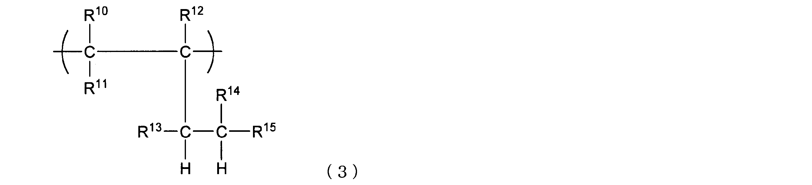
- Examples of the diene compound hydride unit (b) include a unit represented by the following structural formula (2) and a unit represented by the structural formula (3). However, the diene compound hydride unit (b) is not limited depending on its production method.
- R 4 to R 9 are each independently a hydrogen atom, a chain hydrocarbon group, a halogen atom, an alkoxy group, a hydroxyl group, an ester group, a cyano group, an amide group, an imide group, or a silyl group. Or a chain hydrocarbon group substituted with a polar group (halogen atom, alkoxy group, hydroxyl group, ester group, cyano group, amide group, imide group, or silyl group).
- R 4 to R 9 are preferably a hydrogen atom and a chain hydrocarbon group having 1 to 6 carbon atoms from the viewpoints of heat resistance, low birefringence, mechanical strength, and the like.
- the chain hydrocarbon group is preferably a saturated hydrocarbon group, and more preferably an alkyl group.
- R 10 to R 15 each independently represent a hydrogen atom, a chain hydrocarbon group, a halogen atom, an alkoxy group, a hydroxyl group, an ester group, a cyano group, an amide group, an imide group, or a silyl group. Or a chain hydrocarbon group substituted with a polar group (halogen atom, alkoxy group, hydroxyl group, ester group, cyano group, amide group, imide group, or silyl group).
- R 10 to R 15 are preferably a hydrogen atom and a chain hydrocarbon group having 1 to 6 carbon atoms from the viewpoint of heat resistance, low birefringence, mechanical strength, and the like.
- the chain hydrocarbon group is preferably a saturated hydrocarbon group, and more preferably an alkyl group.
- the molecular weight of the block B is preferably 500 or more, more preferably 1000 or more, still more preferably 2000 or more, preferably 50000 or less, more preferably 30000 or less, and even more preferably 20000 or less.
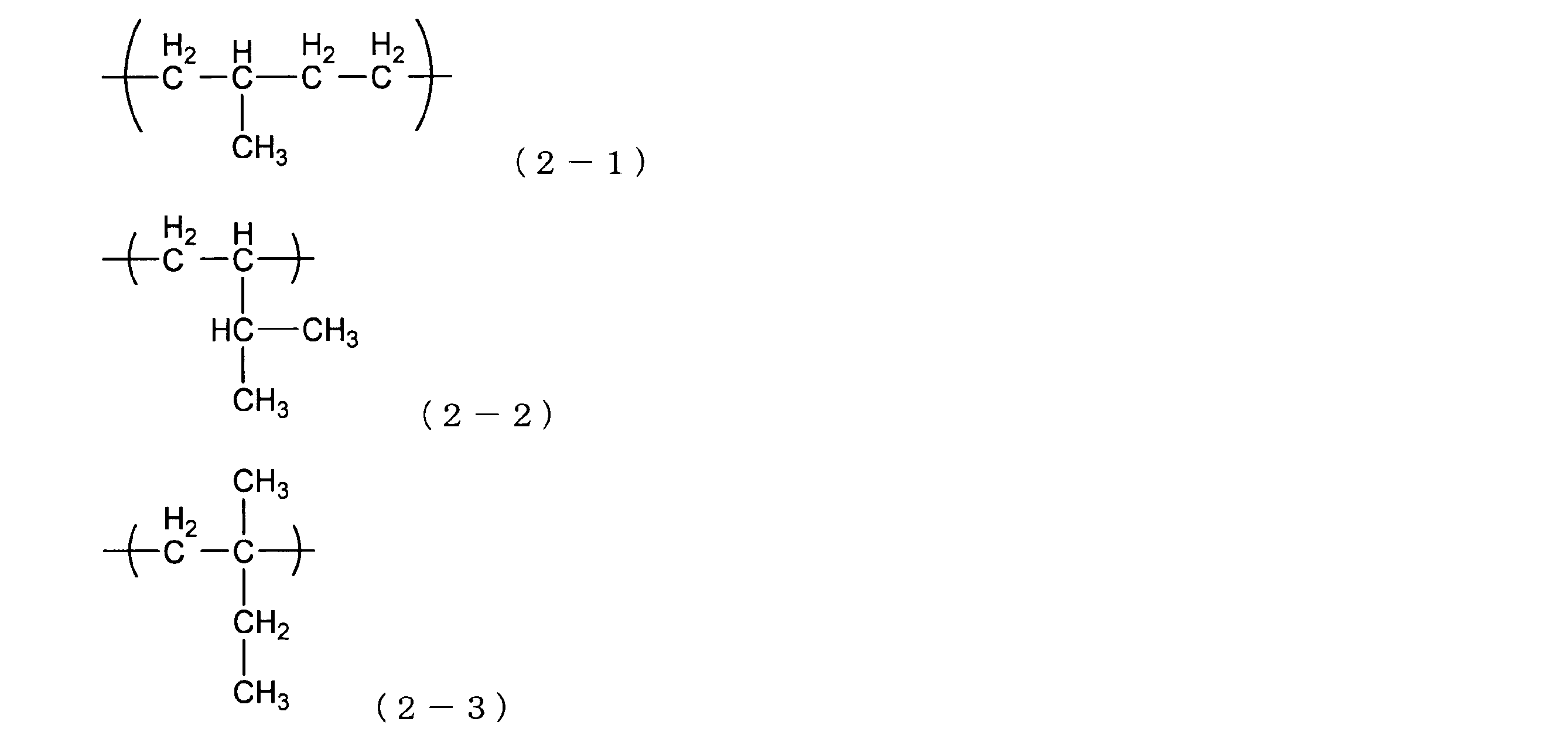
- the diene compound hydride unit (b) is a structural unit having a structure obtained by polymerizing isoprene and hydrogenating it. More specifically, units represented by the following structural formulas (2-1) to (2-3) can be given.
- the ratio (A1 + A2) / B of the total weight of the block A1 and the block A2 to the weight of the block B is preferably 80/20 or more, more preferably 82/18 or more, preferably Is 88/12 or less, more preferably 86/14 or less.
- the triblock copolymer may have any block other than the blocks A1, A2 and B as long as the effects of the present invention are not significantly impaired.
- the triblock copolymer may also contain any unit other than the aromatic vinyl compound hydride unit (a) and the diene compound hydride unit (b) as long as the effects of the present invention are not significantly impaired.
- the number of the arbitrary blocks and the arbitrary units is preferably small.
- the weight ratio of the arbitrary block in the triblock copolymer is not uniform depending on the use of the film, but is preferably 10% by weight or less, more preferably 5% by weight or less, and even more preferably 3% by weight or less. It is particularly preferred that any block is not included.
- the weight ratio of the arbitrary unit in the triblock copolymer is not uniform depending on the use of the film, but is preferably 10% by weight or less, more preferably 5% by weight or less, and even more preferably 3% by weight or less. It is particularly preferred that any unit is not included.
- the weight average molecular weight Mw of the triblock copolymer is preferably 50,000 or more, more preferably 55,000 or more, still more preferably 60,000 or more, preferably 100,000 or less, more preferably 90, 000 or less, and more preferably 80,000 or less.
- the weight average molecular weight Mw is equal to or higher than the lower limit, the impact resistance of the film can be improved, and when the weight average molecular weight Mw is equal to or lower than the upper limit, the viscosity of the polymer can be lowered and the moldability can be improved.
- the molecular weight distribution (weight average molecular weight (Mw) / number average molecular weight (Mn)) of the triblock copolymer is preferably 2 or less, more preferably 1.7 or less, and even more preferably 1.5 or less. When Mw / Mn is within such a range, the polymer viscosity can be lowered to improve the moldability.
- the glass transition temperature Tg A of the triblock copolymer is preferably 110 ° C. or higher, more preferably 115 ° C. or higher, even more preferably 120 ° C. or higher, preferably 150 ° C. or lower, more preferably 148 ° C. or lower, More preferably, it is 145 degrees C or less.
- the glass transition temperature of the triblock copolymer is at least the above lower limit, the advantage that the heat resistance of the film is improved is obtained, and when it is not more than the upper limit, the advantage is obtained that the processing temperature is lowered and the moldability is increased.
- As the glass transition temperature Tg A of the triblock copolymer a higher numerical value can be adopted when a plurality of glass transition temperatures are observed.
- the block copolymer is prepared by preparing monomers corresponding to each of the aromatic vinyl compound hydride block and the diene compound hydride block, and performing block polymerization to obtain a polymer, and then hydrogenating the obtained polymer. It can manufacture by performing.
- Examples of monomers corresponding to aromatic vinyl compound hydride blocks include styrene, ⁇ -methyl styrene, ⁇ -ethyl styrene, ⁇ -propyl styrene, ⁇ -isopropyl styrene, ⁇ -t-butyl styrene, 2-methyl.
- Styrene 3-methylstyrene, 4-methylstyrene, 2,4-diisopropylstyrene, 2,4-dimethylstyrene, 4-t-butylstyrene, 5-t-butyl-2-methylstyrene, monochlorostyrene, dichlorostyrene, Styrenes such as monofluorostyrene and 4-phenylstyrene; vinylcyclohexanes such as vinylcyclohexane and 3-methylisopropenylcyclohexane; 4-vinylcyclohexene, 4-isopropenylcyclohexene, 1-methyl-4-vinylcyclohexene, 1- Methyl-4-isop And vinylcyclohexenes such as lopenylcyclohexene, 2-methyl-4-vinylcyclohexene, 2-methyl-4-isopropenylcyclohexene; and combinations thereof.
- Examples of monomers corresponding to diene compound hydride blocks include chain conjugated dienes such as butadiene, isoprene, 2,3-dimethyl-1,3-butadiene, 1,3-pentadiene, and 1,3-hexadiene. Class; these combinations are listed alongside.
- Polymerization and hydrogenation can be carried out, for example, by the method described in JP2011-13378.
- the resin constituting the optical film may contain an optional component other than the block copolymer.
- optional components include ultraviolet absorbers; inorganic fine particles; stabilizers such as antioxidants, heat stabilizers and near infrared absorbers; resin modifiers such as lubricants and plasticizers; colorants such as dyes and pigments; Antistatic agents; and combinations thereof.
- the amount of the optional component is preferably small.
- the specific amount of the optional component depends on the use and thickness of the film of the present invention, but is preferably 10 parts by weight or less, more preferably 5 parts by weight or less, for example, with respect to 100 parts by weight of the block copolymer. More preferred are parts by weight or less. Among these, it is particularly preferable that other components are not included.
- the optical film of the present invention satisfies the following formulas (1) to (4). 0 nm ⁇ Re (590) ⁇ 3 nm (1)
- Re (400) is an in-plane direction retardation of the optical film at a wavelength of 400 nm
- Re (590) is an in-plane direction retardation of the optical film at a wavelength of 590 nm
- Re (800) is Rth (400) is the thickness direction retardation of the optical film at a wavelength of 400 nm
- Rth (590) is the thickness of the optical film at a wavelength of 590 nm.
- Rth (800) is the thickness direction retardation of the optical film at a wavelength of 800 nm.
- Re (590) is 3 nm or less, preferably 2 nm or less.
- the lower limit of Re (590) is ideally 0 nm.
- is 3 nm or less, preferably 1 nm or less.
- the lower limit of Rth (590) is ideally 0 nm.
- is 1 nm or less, preferably 0.8 nm or less.
- is ideally 0 nm.
- is 1 nm or less, preferably 0.8 nm or less.
- is ideally 0 nm.
- the optical film of the present invention can be preferably used in applications such as a polarizer protective film as a low retardation optical film by satisfying the formulas (1) to (4).
- the optical film of the present invention has a tensile modulus and tear strength within a specific range.
- the tensile elastic modulus is 1500 MPa or more, preferably 1600 MPa or more, and the tear strength is 0.6 N / mm or more, preferably 0.8 N / mm or more.
- the upper limit of a tensile elasticity modulus is not specifically limited, For example, it can be 4000 MPa or less.
- the upper limit of the tear strength is not particularly limited, but may be, for example, 2.0 N / mm or less.
- optical film having the optical properties and mechanical properties described above can be easily selected by appropriately selecting the resin constituting the film from those described above and appropriately selecting the manufacturing conditions from those described below. Can be manufactured.
- the optical film of the present invention has a total light transmittance of preferably 80% or more, more preferably 90% or more, from the viewpoint of stably exhibiting the function as an optical member.
- the optical film of the present invention can be produced as a long film and further cut into a desired dimension when used.
- the dimension in the width direction can be set to, for example, 1000 mm to 3000 mm.
- the thickness of the optical film of the present invention is preferably 10 ⁇ m or more, more preferably 15 ⁇ m or more, still more preferably 20 ⁇ m or more, preferably 200 ⁇ m or less, more preferably 100 ⁇ m or less, and even more preferably 50 ⁇ m or less.
- a polarizing plate protective film by making the thickness of the optical film above the lower limit, there is an advantage that handling properties such as prevention of damage to the polarizing plate are improved, and by making the thickness below the upper limit, the polarizing plate is made thin. There is an advantage that can be.
- the optical film of the present invention is usually a transparent layer and transmits visible light well.
- the specific light transmittance is not uniform depending on the use of the film of the present invention, the light transmittance at a wavelength of 420 to 780 nm is preferably 85% or more, more preferably 88% or more. Since the optical film has such a high light transmittance at a wavelength of 420 to 780 nm, when the optical film is mounted on a display device such as a liquid crystal display device, it is possible to suppress a decrease in luminance particularly during long-term use.
- the optical film of the present invention can be produced by a production method in which a pre-stretch film is prepared using the above-described resin as a material and the pre-stretch film is stretched. Preparation and stretching of the pre-stretched film can be performed, for example, by the method described in JP2011-13378A. By stretching, the optical film can be easily produced as a long film having a large area.
- the optical film of the present invention can be preferably manufactured by a manufacturing method in which a pre-stretch film is stretched at a specific stretch ratio at a specific temperature range.
- the stretching temperature can be defined as a relative value with respect to the glass transition temperature Tg of the resin constituting the film before stretching.
- the stretching temperature is preferably (Tg + 10) ° C. or higher, more preferably (Tg + 15) ° C. or higher, preferably (Tg + 45) ° C. or lower, more preferably (Tg + 40) ° C. or lower.
- the draw ratio is preferably 1.1 times or more, more preferably 1.15 times or more, preferably 3.0 times or less, more preferably 2.75 times or less.
- the optical film can be made into a long film having a large area by stretching, and the retardation of the optical film can be reduced.
- the block copolymer resin described above as the resin constituting the optical film, and by setting the stretching temperature and magnification within the specific range described above, the phase difference is small, An optical film that can be easily transported and has high durability can be easily manufactured as a long film having a large area.
- optical film of the present invention can be suitably used as a protective film for protecting other layers in a display device such as a liquid crystal display device.
- the optical film of this invention is suitable as a polarizer protective film, and is especially suitable as an inner side polarizer protective film of a display apparatus.
- the polarizing plate of the present invention includes a polarizer and the optical film of the present invention.
- the optical film can function as a polarizer protective film.
- the polarizing plate of the present invention may further include an adhesive layer for bonding them between the optical film and the polarizer.
- the polarizer is not particularly limited, and any polarizer can be used.
- the polarizer include those obtained by adsorbing a material such as iodine or a dichroic dye on a polyvinyl alcohol film and then stretching the material.
- the adhesive constituting the adhesive layer include those using various polymers as a base polymer. Examples of such base polymers include acrylic polymers, silicone polymers, polyesters, polyurethanes, polyethers, and synthetic rubbers.
- the polarizing plate of the present invention can realize a display device having good viewing angle characteristics based on the low phase difference. Since the optical film of the present invention can be easily manufactured and has high durability, the polarizing plate of the present invention can also be easily manufactured and can be a highly polarizing plate.
- the polarizing plate of the present invention can usually comprise one layer of polarizer and two layers of protective films provided on both sides thereof. Of these two protective films, both may be the optical film of the present invention, and only one of them may be the optical film of the present invention.
- the optical film of the present invention is used as a protective film used at a position closer to the liquid crystal cell than the polarizer. It is particularly preferred to provide a film.
- a known protective film can be appropriately selected as the optional protective film.
- a film made of a resin containing an alicyclic structure-containing polymer can be used. More specifically, a film made of a resin such as “ZEONOR” (manufactured by Nippon Zeon Co., Ltd.) can be used.
- the liquid crystal display device is not particularly limited, and may be a liquid crystal display device of any type.
- a liquid crystal display device including an IPS mode liquid crystal cell is particularly preferable because the optical film of the present invention has a remarkable effect of suppressing light leakage at an oblique viewing angle and suppressing color unevenness.
- Re and Rth of the optical film were measured by using “AxoScan” manufactured by AXOMETRICS at wavelengths of 400, 590, and 800 nm, R 0 (retardation observed from 0 ° polar angle), R 40 (polar angle 40 ° direction).
- the retardation Re in the in-plane direction and the retardation Rth in the thickness direction were calculated from the retardation observed from 1) and the average refractive index.
- the tensile elastic modulus of the optical film was measured according to JIS K7162. However, the test piece was prepared according to JIS K7127-1B. The tensile speed was measured as 5 mm / min. Both the measurement by the tension along the longitudinal direction of the long optical film and the measurement by the tension along the width direction were performed, and the average value thereof was taken as the measurement value.
- the tear strength of the optical film was measured according to the trouser tear method (JIS K7128-1). Both the measurement by tearing along the longitudinal direction of the long optical film and the measurement by tearing along the width direction were performed, and the average value thereof was taken as the measurement value.
- FIG. 1 is a rear view of the trimming apparatus used for trimming as viewed from the downstream side in the optical film transport direction.
- the lower blade 122 in FIG. 1 is shown by a longitudinal sectional view taken along a plane passing through the rotation shaft 122C.
- the trimming device 120 is a pair of devices aligned in the TD direction (direction parallel to the width direction of the film being conveyed).
- the long optical film is transported in the horizontal direction, and the dish-shaped upper blade 121 disposed on the upper side of the optical film transport path is rotated around the rotation shaft 121C, so that A part of the outer periphery is rotated by rotating a bowl-shaped lower blade 122 with a part thereof in contact with the upper surface of the optical film and arranged on the lower side of the conveyance path of the optical film about the rotation shaft 122C.
- the rotating shaft 121C of the upper blade 121 and the rotating shaft 122C of the lower blade 122 are both arranged in a direction parallel to the TD direction.
- the upper blade 121 and the lower blade 122 were overlapped so as to shear the optical film, and the saddle-shaped lower blade 122 was arranged so that the edge protruded to the side surface side of the upper blade 121.
- a commercially available television receiver was prepared as an IPS type liquid crystal display device.
- the polarizing plate on the viewing side of this television receiver (that is, the polarizing plate closer to the display surface) was removed, and the polarizing plate produced in the example or comparative example was attached instead.
- the orientation of the polarizing plate was adjusted so that the optical film was on the light source side and the absorption axis of the polarizer was the same as the orientation of the polarizer in the polarizing plate originally provided in the television receiver.
- the television receiver was set in a black display state (a state in which a black color was displayed on the entire display surface), and the display surface was observed.
- the observation was performed in the range of the azimuth angle of 0 ° to 180 ° from the direction where the polar angle with respect to the display surface is about 40 °. As a result of observation, when a color such as a bluish color was confirmed on the display surface, it was determined to be bad, and when the color was not confirmed, it was determined to be good.
- the polarizing plate produced in the example or the comparative example was cut to obtain a square film piece of 100 mm ⁇ 100 mm.
- the surface on the optical film side of the obtained film piece was subjected to corona treatment.
- the corona treatment was performed under the same conditions as those performed in the production of the polarizing plate.
- the corona-treated surface of the polarizing plate was bonded to an optical glass (Corning EagleXG thickness 0.7 mm) through a layer of an adhesive (CS9621T manufactured by Nitto Denko Corporation) to obtain a bonded product.
- the paste was subjected to a thermal shock test.
- the thermal shock test was performed using a thermal shock tester (manufactured by Espec). The conditions of the thermal shock test were 70 ° C. for 30 minutes followed by ⁇ 40 ° C. for 30 minutes, and 100 cycles were repeated. After completion of the thermal shock test, the bonded product was taken out. When the end of the polarizing plate was lifted by 2 mm or more due to the curling of the polarizing plate, it was determined to be defective, and when the lifting amount was less than 2 mm, it was determined to be good.
- Example 1 (1-1. First stage reaction: elongation of aromatic vinyl compound hydride block A1) A stainless steel reactor equipped with a stirrer and thoroughly dried and purged with nitrogen was charged with 320 parts of dehydrated cyclohexane, 75 parts of styrene and 0.38 part of dibutyl ether, and stirred at 60 ° C. to give an n-butyllithium solution. (15 wt% hexane solution) 0.41 part was added to initiate the polymerization reaction, and the first stage polymerization reaction was carried out for 1 hour. At 1 hour after the start of the reaction, a sample was sampled from the reaction mixture and analyzed by gas chromatography (GC). As a result, the polymerization conversion was 99.5%.
- GC gas chromatography
- a mixture containing a copolymer having a triblock molecular structure of styrene-isoprene-styrene was obtained.
- the mixture containing the block copolymer obtained in the step (1-3) is transferred to a pressure-resistant reactor equipped with a stirrer, and a diatomaceous earth-supported nickel catalyst (manufactured by JGC Catalysts & Chemicals, Inc.) is used as a hydrogenation catalyst.
- E22U nickel loading 60%
- 8.0 parts and dehydrated cyclohexane 100 parts were added and mixed.
- the inside of the reactor was replaced with hydrogen gas, and hydrogen was supplied while stirring the solution.
- a hydrogenation reaction was performed at a temperature of 190 ° C. and a pressure of 4.5 MPa for 6 hours.
- a reaction solution containing a block copolymer in which the copolymer was hydrogenated by a hydrogenation reaction was obtained. After completion of the hydrogenation reaction, the reaction solution was filtered to remove the hydrogenation catalyst, and then the phenolic antioxidant pentaerythrityl tetrakis [3- (3,5-di-t-butyl-4-hydroxyphenyl) ) Propionate] ("Songnox 1010" manufactured by Matsubara Sangyo Co., Ltd.) 2.0 parts of xylene solution in which 0.1 part was dissolved was added and dissolved. Next, the above solution is mixed with cyclohexane, xylene and other volatile components as solvents from a solution at a temperature of 260 ° C.
- the block copolymer contained in the obtained pellets had a weight average molecular weight (Mw) of 65,000, a molecular weight distribution (Mw / Mn) of 1.25, and a hydrogenation rate of almost 100%.
- Optical film The pellets obtained in the step (1-4) were heated and melted and molded by extrusion to obtain a long original film.
- the thickness of the raw film was 48 ⁇ m.
- the raw film was stretched in the width direction by a tenter stretching machine. The stretching temperature was 160 ° C. and the stretching ratio was 1.2 times. By such stretching, an optical film having a thickness of 40 ⁇ m was obtained.
- Re (590), Rth (590), Re (400) -Re (800), Rth (400) -Rth (800), tensile elastic modulus and tear strength were measured, and the transportability was measured. evaluated.
- polarizer protective film a film made of a resin containing an alicyclic structure-containing polymer (trade name “Zeonor Film ZF14”, manufactured by Nippon Zeon Co., Ltd., glass transition temperature 136 ° C., thickness 40 ⁇ m) was used.
- a corona treatment device manufactured by Kasuga Denki Co., Ltd. was used for the corona treatment.
- the condition of the corona treatment was a discharge amount of 50 W ⁇ min / m 2 .
- a polarizer a polyvinyl alcohol polarizer (thickness: 23 ⁇ m) was used. Bonding is an arrangement in which the polarizer and the corona-treated surface of the optical film and the polarizer protective film face each other, and these are overlapped through a layer of adhesive (Toyochem Dynaleo CRB series), and a roll laminator is used. This was done by pressure bonding.
- the resulting multilayer film was irradiated with UV.
- UV irradiation is performed by using a UV irradiation apparatus (manufactured by Fusion) equipped with a high-pressure mercury light source under the conditions of a peak illuminance of 350 mW / cm 2 and an integrated light quantity of 500 mJ / cm 2 from the light source to the surface on the optical film side. Performed by irradiation.
- the adhesive was cured to obtain a polarizing plate having a layer structure of (polarizer protective film) / (adhesive layer) / (polarizer) / (adhesive layer) / (optical film).
- the obtained polarizing plate was evaluated for viewing angle characteristics and curl.
- Example 2 The optical film and the polarizing plate were obtained and evaluated by the same operation as in Example 1 except for the following changes.
- step (1-5) the extrusion conditions were changed, and the thickness of the raw film was set to 60 ⁇ m.
- step (1-5) the draw ratio was changed to 1.5 times.
- the thickness of the obtained optical film was 40 ⁇ m.
- Example 3 The optical film and the polarizing plate were obtained and evaluated by the same operation as in Example 1 except for the following changes.
- step (1-5) the extrusion molding conditions were changed, and the thickness of the raw film was 120 ⁇ m.
- step (1-5) the draw ratio was changed to 3.0 times.
- the thickness of the obtained optical film was 40 ⁇ m.
- Example 4 The optical film and the polarizing plate were obtained and evaluated by the same operation as in Example 1 except for the following changes.
- the amount of styrene used in step (1-1) was changed to 60 parts
- the amount of isoprene used in step (1-2) was changed to 20 parts
- the amount of styrene used in step (1-3) was changed to 20 parts. Changed to the department.
- the block copolymer contained in the obtained pellet had a weight average molecular weight (Mw) of 65,000, a molecular weight distribution (Mw / Mn) of 1.24, and a hydrogenation rate of almost 100%.
- Mw weight average molecular weight
- Mw / Mn molecular weight distribution
- hydrogenation rate a hydrogenation rate of almost 100%.
- the extrusion molding conditions were changed, and the thickness of the raw film was set to 100 ⁇ m.
- the draw ratio was changed to 2.5 times.
- the thickness of the obtained optical film was 40 ⁇ m.
- Example 5 The optical film and the polarizing plate were obtained and evaluated by the same operation as in Example 1 except for the following changes. -The amount of styrene used in step (1-1) was changed to 78 parts, the amount of isoprene used in step (1-2) was changed to 12 parts, and the amount of styrene used in step (1-3) was 10 parts. Changed to the department.
- the block copolymer contained in the obtained pellet had a weight average molecular weight (Mw) of 64,000, a molecular weight distribution (Mw / Mn) of 1.33, and a hydrogenation rate of almost 100%.
- Mw weight average molecular weight
- Mw / Mn molecular weight distribution
- hydrogenation rate hydrogenation rate
- Step (1-5) The optical film and the polarizing plate were obtained and evaluated by the same operation as in Example 1 except for the following changes.
- step (1-5) the extrusion molding conditions were changed, and the thickness of the raw film was 40 ⁇ m.
- Step (1-5) the original film was directly obtained as an optical film without stretching.
- Example 2 The optical film and the polarizing plate were obtained and evaluated by the same operation as in Example 1 except for the following changes. -The amount of styrene used in step (1-1) was changed to 60 parts, the amount of isoprene used in step (1-2) was changed to 30 parts, and the amount of styrene used in step (1-3) was 10 parts. Changed to the department.
- the block copolymer contained in the obtained pellet had a weight average molecular weight (Mw) of 65,000, a molecular weight distribution (Mw / Mn) of 1.44, and a hydrogenation rate of almost 100%.
- Mw weight average molecular weight
- Mw / Mn molecular weight distribution
- hydrogenation rate a hydrogenation rate of almost 100%.
- the extrusion conditions were changed, and the thickness of the raw film was set to 60 ⁇ m.
- the draw ratio was changed to 1.5 times.
- the thickness of the obtained optical film was 40 ⁇ m.
- Example 3 The optical film and the polarizing plate were obtained and evaluated by the same operation as in Example 1 except for the following changes. -The amount of styrene used in step (1-1) was changed to 80 parts, the amount of isoprene used in step (1-2) was changed to 10 parts, and the amount of styrene used in step (1-3) was changed to 10 parts. Changed to the department.
- the block copolymer contained in the obtained pellet had a weight average molecular weight (Mw) of 64000, a molecular weight distribution (Mw / Mn) of 1.44, and a hydrogenation rate of almost 100%.
- Mw weight average molecular weight
- Mw / Mn molecular weight distribution
- hydrogenation rate a hydrogenation rate of almost 100%.
- the extrusion conditions were changed, and the thickness of the raw film was set to 60 ⁇ m.
- the draw ratio was changed to 1.5 times.
- the thickness of the obtained optical film was 40 ⁇ m.
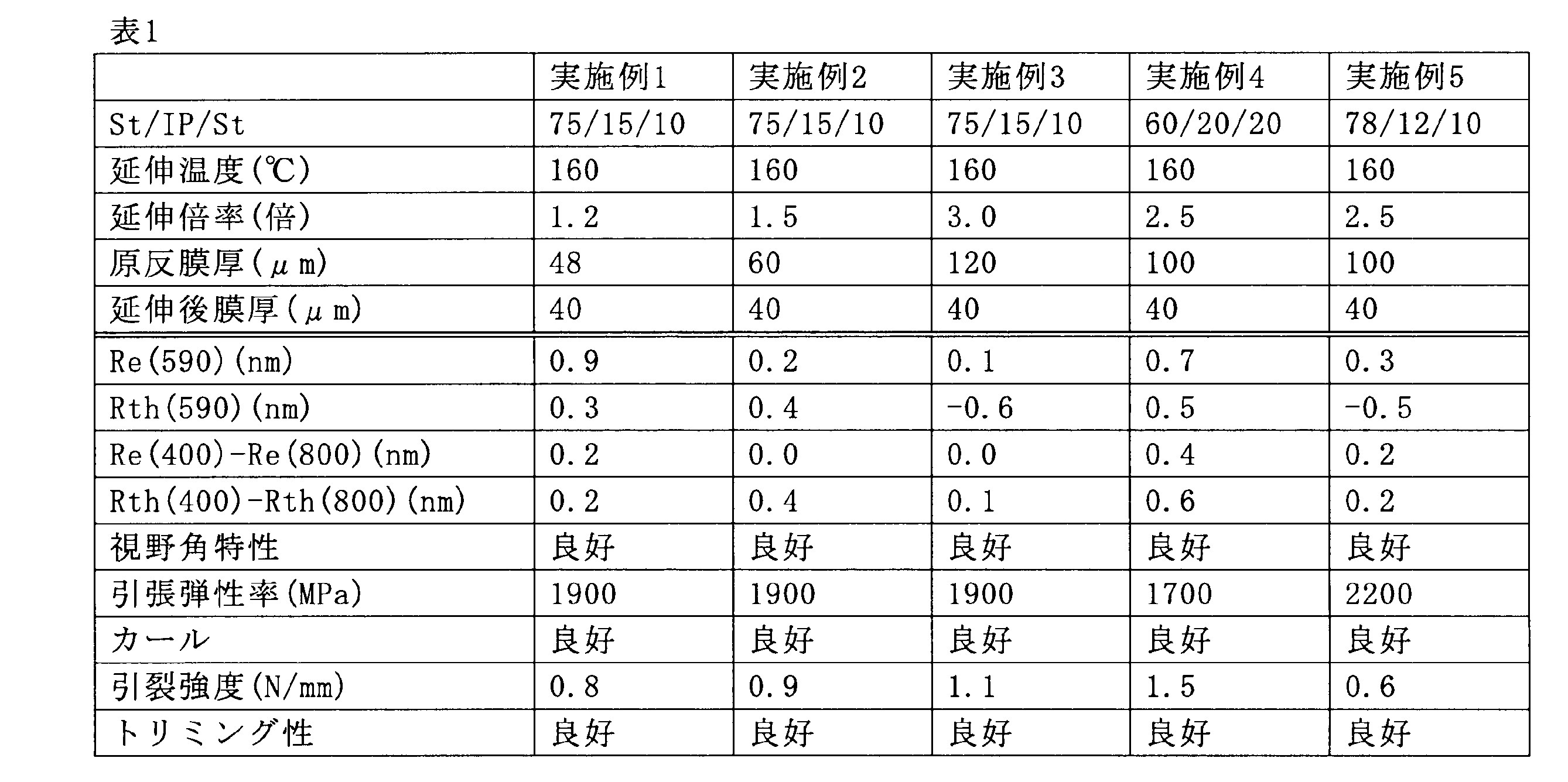
- Tables 1 and 2 show the results of Examples and Comparative Examples.
- St / IP / St The type of polymer constituting the optical film.
- styrene-isoprene-styrene triblock copolymer the block weight ratio.
- COP cycloolefin polymer
- TAC triacetyl cellulose.
- the optical film and the polarizing plate of the present invention are excellent in curling suppression and trimming properties and can constitute a liquid crystal display device having good viewing angle characteristics.
- Cut optical film 12 End film 120: Trimming device 121: Upper blade 121C: Rotating shaft 122: Lower blade 122C: Rotating shaft
Landscapes
- Physics & Mathematics (AREA)
- Chemical & Material Sciences (AREA)
- Engineering & Computer Science (AREA)
- Manufacturing & Machinery (AREA)
- Optics & Photonics (AREA)
- General Physics & Mathematics (AREA)
- Nonlinear Science (AREA)
- Organic Chemistry (AREA)
- Polymers & Plastics (AREA)
- Mechanical Engineering (AREA)
- Medicinal Chemistry (AREA)
- Mathematical Physics (AREA)
- Crystallography & Structural Chemistry (AREA)
- Chemical Kinetics & Catalysis (AREA)
- Health & Medical Sciences (AREA)
- Materials Engineering (AREA)
- Polarising Elements (AREA)
- Shaping By String And By Release Of Stress In Plastics And The Like (AREA)
- Graft Or Block Polymers (AREA)
Abstract
Description
本発明のさらなる目的は、視野角特性が良好な表示装置を実現でき、容易に製造でき、且つ耐久性が高い偏光板を提供することにある。
0nm≦Re(590)≦3nm (1)
|Rth(590)|≦3nm (2)
|Re(400)-Re(800)|≦1nm (3)
|Rth(400)-Rth(800)|≦1nm (4)
(但し、
Re(400)は、前記光学フィルムの波長400nmにおける面内方向レターデーションであり、
Re(590)は、前記光学フィルムの波長590nmにおける面内方向レターデーションであり、
Re(800)は、前記光学フィルムの波長800nmにおける面内方向レターデーションであり、
Rth(400)は、前記光学フィルムの波長400nmにおける厚み方向レターデーションであり、
Rth(590)は、前記光学フィルムの波長590nmにおける厚み方向レターデーションであり、
Rth(800)は、前記光学フィルムの波長800nmにおける厚み方向レターデーションである。)
引張弾性率が1500MPa以上であり、
引裂強度が0.6N/mm以上である、光学フィルム。
〔2〕 前記樹脂が、芳香族ビニル化合物水素化物単位(a)及びジエン化合物水素化物単位(b)を有する重合体を含む、〔1〕に記載の光学フィルム。
〔3〕 前記重合体が、
前記ジエン化合物水素化物単位(b)を有する、1分子あたり1つのブロックBと、
前記ブロックBの一端に連結され、前記芳香族ビニル化合物水素化物単位(a)を有する、1分子あたり1つのブロックA1と、
前記ブロックBの他端に連結され、前記芳香族ビニル化合物水素化物単位(a)を有する、1分子あたり1つのブロックA2と
を含むトリブロック共重合体である、〔2〕に記載の光学フィルム。
〔4〕 前記トリブロック共重合体において、前記ブロックA1及び前記ブロックA2の合計の重量と、前記ブロックBの重量との比(A1+A2)/Bが、80/20以上88/12以下である、〔3〕に記載の光学フィルム。
〔5〕 前記芳香族ビニル化合物水素化物単位(a)が、スチレンを重合し水素化して得られる構造を有する構造単位であり、
前記ジエン化合物水素化物単位(b)が、イソプレンを重合し水素化して得られる構造を有する構造単位である、〔2〕~〔4〕のいずれか1項に記載の光学フィルム。
〔6〕 偏光子と、〔1〕~〔5〕のいずれか1項に記載の光学フィルムとを備える、偏光板。
〔7〕 〔1〕~〔5〕のいずれか1項に記載の光学フィルムの製造方法であって、
前記樹脂のガラス転移温度がTgであり、
前記樹脂からなる延伸前フィルムを、(Tg+10)℃以上(Tg+45)℃以下の温度において、1.1倍以上3.0倍以下の延伸倍率で延伸することを含む製造方法。
本発明によればまた、視野角特性が良好な表示装置を実現でき、容易に製造でき、且つ耐久性が高い偏光板を提供することができる。
本発明の光学フィルムは、延伸された樹脂からなる。
延伸された樹脂からなるフィルムとは、樹脂をフィルムの形状に成形し、さらにそれを延伸の工程に供することにより延伸して得られるフィルムである。本願においては、かかる延伸の工程に供する前のフィルムを「延伸前フィルム」ということがある。
以下の単位の例示物において立体異性体を有するものは、そのいずれの立体異性体をも使用することができる。ブロックA1、A2及びBは、複数種類の異なる単位を含みうる。またブロック共重合体は複数種類の異なるブロックを含む複数種類の重合体の混合物であってもよい。ブロック共重合体の構造、水素化率等は、NMR法により確認しうる。



本発明の光学フィルムは、下記式(1)~(4)を満たす。
0nm≦Re(590)≦3nm (1)
|Rth(590)|≦3nm (2)
|Re(400)-Re(800)|≦1nm (3)
|Rth(400)-Rth(800)|≦1nm (4)
式中、Re(400)は、前記光学フィルムの波長400nmにおける面内方向レターデーションであり、Re(590)は、前記光学フィルムの波長590nmにおける面内方向レターデーションであり、Re(800)は、前記光学フィルムの波長800nmにおける面内方向レターデーションであり、Rth(400)は、前記光学フィルムの波長400nmにおける厚み方向レターデーションであり、Rth(590)は、前記光学フィルムの波長590nmにおける厚み方向レターデーションであり、Rth(800)は、前記光学フィルムの波長800nmにおける厚み方向レターデーションである。
本発明の光学フィルムは、上に述べた樹脂を材料として延伸前フィルムを調製し、延伸前フィルムを延伸する製造方法により製造しうる。延伸前フィルムの調製及び延伸は、例えば、特開2011-13378号公報に記載の方法により行いうる。延伸を行うことにより、光学フィルムを、大面積の長尺フィルムとして容易に製造することができる。
本発明の光学フィルムは、液晶表示装置などの表示装置において、他の層を保護する保護フィルムとして好適に用いうる。中でも、本発明の光学フィルムは、偏光子保護フィルムとして好適であり、表示装置の内側偏光子保護フィルムとして特に好適である。
以下の説明において、量を表す「%」及び「部」は、別に断らない限り重量基準である。また、以下に説明する操作は、別に断らない限り、常温及び常圧の条件において行った。
〔分子量〕
重合体(ブロック共重合体、及びその製造の中間体としての重合体)の重量平均分子量及び数平均分子量は、THFを溶離液とするGPCによる標準ポリスチレン換算値として38℃において測定した。測定装置としては、東ソー社製HLC8020GPCを用いた。
光学フィルムのRe及びRthは、AXOMETRICS社製「AxoScan」を用いて、測定波長400、590及び800nmで、R0(極角0°方向から観察したレターデーション)、R40(極角40°方向から観察したレターデーション)および平均屈折率から面内方向のレターデーションRe、及び厚み方向のレターデーションRthを算出した。
光学フィルムの引張弾性率は、JIS K7162に準拠して測定した。但し試験片はJIS K7127-1Bに準拠して作製した。引っ張り速度は5mm/minとして測定した。長尺の光学フィルムの長手方向に沿った引張による測定及び幅方向に沿った引張による測定の両方を行い、それらの平均値を測定値とした。
光学フィルムの引裂強度は、トラウザー引裂法(JIS K7128-1)に従って測定した。長尺の光学フィルムの長手方向に沿った引裂きによる測定及び幅方向に沿った引裂きによる測定の両方を行い、それらの平均値を測定値とした。
長尺の光学フィルムを、搬送速度5m/分で、フィルム長手方向に沿って水平に搬送した。搬送される光学フィルムを、図1に示すトリミング装置を用いて、連続的にトリミングした。トリミングを30分間行い、その間にフィルムの破断が生じなかった。
光学フィルムを搬送速度5m/minでその長手方向に搬送しながら、30分間、光学フィルムのトリミングを続けた。そして、トリミングによるクラックを原因とする光学フィルムの破断が発生したものは不良と判定し、そのような破断が発生しなかったものは良好と判定した。ここで光学フィルムの破断とは、光学フィルムが長手方向以外の方向に断ち切られる現象をいう。
IPS型液晶表示装置として市販のテレビ受像機を用意した。
このテレビ受像機の視認側の偏光板(即ち、表示面に近い方の偏光板)を取り外し、代わりに、実施例又は比較例で製造した偏光板を取り付けた。偏光板の向きは、光学フィルムが光源側となり、且つ偏光子の吸収軸が、テレビ受像機がもともと備えていた偏光板における偏光子の向きと同じ方向となるよう調整した。
テレビ受像機を黒表示状態(表示面全体に黒い色を表示した状態)にして、表示面を観察した。観察は、表示面に対する極角がおよそ40°である方向から、方位角0°~180°の範囲において行った。観察の結果、表示面において、青味がかった色味等の色味が確認された場合は不良と判定し、色味が確認されなかった場合は良好と判定した。
実施例又は比較例で製造した偏光板を裁断し、100mm×100mmの正方形のフィルム片を得た。得られたフィルム片の光学フィルム側の面に、コロナ処理を施した。コロナ処理は、偏光板の製造において実施した条件と同じ条件とした。偏光板のコロナ処理された面を、粘着剤(日東電工社製CS9621T)の層を介して、光学用ガラス(コーニング社製EagleXG 厚み0.7mm)に貼合し、貼合物とした。
(1-1.第1段階の反応:芳香族ビニル化合物水素化物ブロックA1の伸長)
十分に乾燥し窒素置換した、攪拌装置を備えたステンレス鋼製反応器に、脱水シクロヘキサン320部、スチレン75部、及びジブチルエーテル0.38部を仕込み、60℃で攪拌しながらn-ブチルリチウム溶液(15重量%含有ヘキサン溶液)0.41部を添加して重合反応を開始させ、1時間、第1段階の重合反応を行った。反応開始後1時間の時点で、反応混合物から、試料をサンプリングし、ガスクロマトグラフィー(GC)により分析した結果、重合転化率は99.5%であった。
前記工程(P1-1)で得られた反応混合物に、イソプレン15部を添加し、引き続き第2段階の重合反応を開始し、1時間、重合反応を行った。第2段階の重合反応開始後1時間の時点で、反応混合物から、試料をサンプリングし、GCにより分析した結果、重合転化率は99.5%であった。
前記工程(1-2)で得られた反応混合物に、スチレン10部を添加し、引き続き第3段階の重合反応を開始した。第3段階の重合反応開始後1時間の時点で、反応混合物から、試料をサンプリングし、共重合体の重量平均分子量Mw及び数平均分子量Mnを測定した。またこの時点でサンプリングした試料をGCにより分析した結果、重合転化率はほぼ100%であった。その後直ちに、反応混合物にイソプロピルアルコール0.2部を添加して反応を停止させた。これにより、スチレン-イソプレン-スチレンのトリブロック分子構造を有する共重合体を含む混合物を得た。
得られた共重合体は、スチレン/イソプレン/スチレン=75/15/10の重量比のトリブロック分子構造を有する共重合体であった。
次に、工程(1-3)で得られたブロック共重合体を含む混合物を、攪拌装置を備えた耐圧反応器に移送し、水素化触媒として珪藻土担持型ニッケル触媒(日揮触媒化成社製「E22U」、ニッケル担持量60%)8.0部及び脱水シクロヘキサン100部を添加して混合した。反応器内部を水素ガスで置換し、さらに溶液を攪拌しながら水素を供給し、温度190℃、圧力4.5MPaにて6時間水素化反応を行った。水素化反応により共重合体が水素化された、ブロック共重合体を含む反応溶液を得た。
水素化反応終了後、反応溶液をろ過して水素化触媒を除去した後、フェノール系酸化防止剤であるペンタエリスリチル・テトラキス[3-(3,5-ジ-t-ブチル-4-ヒドロキシフェニル)プロピオネート](松原産業社製「Songnox1010」)0.1部を溶解したキシレン溶液2.0部を添加して溶解させた。
次いで、上記溶液を、円筒型濃縮乾燥器(日立製作所社製「コントロ」)を用いて、温度260℃、圧力0.001MPa以下で、溶液から、溶媒であるシクロヘキサン、キシレン及びその他の揮発成分を除去した。溶融ポリマーをダイからストランド状に押出し、冷却後、ペレタイザーによりブロック共重合体のペレット95部を作製した。
得られたペレットに含まれるブロック共重合体の重量平均分子量(Mw)は65000、分子量分布(Mw/Mn)は1.25、水素化率はほぼ100%であった。
工程(1-4)で得たペレットを加熱して溶融し、押出成形により成形し、長尺の原反フィルムとした。原反フィルムの厚みは48μmであった。
原反フィルムを、テンター延伸機により、幅方向に延伸した。延伸温度は160℃、延伸倍率は1.2倍とした。かかる延伸により、厚み40μmの光学フィルムを得た。
得られた光学フィルムについて、Re(590)、Rth(590)、Re(400)-Re(800)、Rth(400)-Rth(800)、引張弾性率及び引裂強度を測定し、搬送性を評価した。
工程(1-5)で得た光学フィルムの一方の面および偏光子保護フィルムの一方の面に、コロナ処理を施した。偏光子保護フィルムとしては、脂環式構造含有重合体を含む樹脂からなるフィルム(商品名「ゼオノアフィルムZF14」、日本ゼオン株式会社製、ガラス転移温度136℃、厚み40μm)を用いた。コロナ処理にはコロナ処理装置(春日電機社製)を用いた。コロナ処理の条件は、放電量50W・min/m2とした。
得られた偏光板について、視野角特性及びカールを評価した。
下記の変更点の他は、実施例1と同じ操作により、光学フィルム及び偏光板を得て評価した。
・工程(1-5)において、押出成形の条件を変更し、原反フィルムの厚みを60μmとした。
・工程(1-5)において、延伸倍率を1.5倍に変更した。得られた光学フィルムの厚みは40μmであった。
下記の変更点の他は、実施例1と同じ操作により、光学フィルム及び偏光板を得て評価した。
・工程(1-5)において、押出成形の条件を変更し、原反フィルムの厚みを120μmとした。
・工程(1-5)において、延伸倍率を3.0倍に変更した。得られた光学フィルムの厚みは40μmであった。
下記の変更点の他は、実施例1と同じ操作により、光学フィルム及び偏光板を得て評価した。
・工程(1-1)におけるスチレンの使用量を60部に変更し、工程(1-2)におけるイソプレンの使用量を20部に変更し、工程(1-3)におけるスチレンの使用量を20部に変更した。工程(1-3)で得られた共重合体は、スチレン/イソプレン/スチレン=60/20/20の重量比のトリブロック分子構造を有する共重合体であった。その後得られたペレットに含まれるブロック共重合体の重量平均分子量(Mw)は65000、分子量分布(Mw/Mn)は1.24、水素化率はほぼ100%であった。
・工程(1-5)において、押出成形の条件を変更し、原反フィルムの厚みを100μmとした。
・工程(1-5)において、延伸倍率を2.5倍に変更した。得られた光学フィルムの厚みは40μmであった。
下記の変更点の他は、実施例1と同じ操作により、光学フィルム及び偏光板を得て評価した。
・工程(1-1)におけるスチレンの使用量を78部に変更し、工程(1-2)におけるイソプレンの使用量を12部に変更し、工程(1-3)におけるスチレンの使用量を10部に変更した。工程(1-3)で得られた共重合体は、スチレン/イソプレン/スチレン=78/12/10の重量比のトリブロック分子構造を有する共重合体であった。その後得られたペレットに含まれるブロック共重合体の重量平均分子量(Mw)は64000、分子量分布(Mw/Mn)は1.33、水素化率はほぼ100%であった。
・工程(1-5)において、押出成形の条件を変更し、原反フィルムの厚みを100μmとした。
・工程(1-5)において、延伸倍率を2.5倍に変更した。得られた光学フィルムの厚みは40μmであった。
下記の変更点の他は、実施例1と同じ操作により、光学フィルム及び偏光板を得て評価した。
・工程(1-5)において、押出成形の条件を変更し、原反フィルムの厚みを40μmとした。
・工程(1-5)において、延伸を行わず、原反フィルムをそのまま光学フィルムとして得た。
下記の変更点の他は、実施例1と同じ操作により、光学フィルム及び偏光板を得て評価した。
・工程(1-1)におけるスチレンの使用量を60部に変更し、工程(1-2)におけるイソプレンの使用量を30部に変更し、工程(1-3)におけるスチレンの使用量を10部に変更した。工程(1-3)で得られた共重合体は、スチレン/イソプレン/スチレン=60/30/10の重量比のトリブロック分子構造を有する共重合体であった。その後得られたペレットに含まれるブロック共重合体の重量平均分子量(Mw)は65000、分子量分布(Mw/Mn)は1.44、水素化率はほぼ100%であった。
・工程(1-5)において、押出成形の条件を変更し、原反フィルムの厚みを60μmとした。
・工程(1-5)において、延伸倍率を1.5倍に変更した。得られた光学フィルムの厚みは40μmであった。
下記の変更点の他は、実施例1と同じ操作により、光学フィルム及び偏光板を得て評価した。
・工程(1-1)におけるスチレンの使用量を80部に変更し、工程(1-2)におけるイソプレンの使用量を10部に変更し、工程(1-3)におけるスチレンの使用量を10部に変更した。工程(1-3)で得られた共重合体は、スチレン/イソプレン/スチレン=80/10/10の重量比のトリブロック分子構造を有する共重合体であった。その後得られたペレットに含まれるブロック共重合体の重量平均分子量(Mw)は64000、分子量分布(Mw/Mn)は1.44、水素化率はほぼ100%であった。
・工程(1-5)において、押出成形の条件を変更し、原反フィルムの厚みを60μmとした。
・工程(1-5)において、延伸倍率を1.5倍に変更した。得られた光学フィルムの厚みは40μmであった。
脂環式構造含有重合体を含む樹脂からなるフィルム(商品名「ゼオノアフィルムZF14」、日本ゼオン株式会社製、ガラス転移温度136℃、厚み40μm)を、そのまま光学フィルムとして評価した。さらに、このフィルムを、(1-5)で得た光学フィルムの代わりに用いた他は、実施例1の(1-6)と同じ操作により、偏光板を得て評価した。
トリアセチルセルロースフィルム(コニカミノルタ社製「ゼロタック(登録商標)」、厚み40μm)を、そのまま光学フィルムとして評価した。さらに、このフィルムを、(1-5)で得た光学フィルムの代わりに用いた他は、実施例1の(1-6)と同じ操作により、偏光板を得て評価した。

12:端部フィルム
120:トリミング装置
121:上刃
121C:回転軸
122:下刃
122C:回転軸
Claims (7)
- 延伸された樹脂からなる光学フィルムであって、下記式(1)~(4)を満たし:
0nm≦Re(590)≦3nm (1)
|Rth(590)|≦3nm (2)
|Re(400)-Re(800)|≦1nm (3)
|Rth(400)-Rth(800)|≦1nm (4)
(但し、
Re(400)は、前記光学フィルムの波長400nmにおける面内方向レターデーションであり、
Re(590)は、前記光学フィルムの波長590nmにおける面内方向レターデーションであり、
Re(800)は、前記光学フィルムの波長800nmにおける面内方向レターデーションであり、
Rth(400)は、前記光学フィルムの波長400nmにおける厚み方向レターデーションであり、
Rth(590)は、前記光学フィルムの波長590nmにおける厚み方向レターデーションであり、
Rth(800)は、前記光学フィルムの波長800nmにおける厚み方向レターデーションである。)
引張弾性率が1500MPa以上であり、
引裂強度が0.6N/mm以上である、光学フィルム。 - 前記樹脂が、芳香族ビニル化合物水素化物単位(a)及びジエン化合物水素化物単位(b)を有する重合体を含む、請求項1に記載の光学フィルム。
- 前記重合体が、
前記ジエン化合物水素化物単位(b)を有する、1分子あたり1つのブロックBと、
前記ブロックBの一端に連結され、前記芳香族ビニル化合物水素化物単位(a)を有する、1分子あたり1つのブロックA1と、
前記ブロックBの他端に連結され、前記芳香族ビニル化合物水素化物単位(a)を有する、1分子あたり1つのブロックA2と
を含むトリブロック共重合体である、請求項2に記載の光学フィルム。 - 前記トリブロック共重合体において、前記ブロックA1及び前記ブロックA2の合計の重量と、前記ブロックBの重量との比(A1+A2)/Bが、80/20以上88/12以下である、請求項3に記載の光学フィルム。
- 前記芳香族ビニル化合物水素化物単位(a)が、スチレンを重合し水素化して得られる構造を有する構造単位であり、
前記ジエン化合物水素化物単位(b)が、イソプレンを重合し水素化して得られる構造を有する構造単位である、請求項2~4のいずれか1項に記載の光学フィルム。 - 偏光子と、請求項1~5のいずれか1項に記載の光学フィルムとを備える、偏光板。
- 請求項1~5のいずれか1項に記載の光学フィルムの製造方法であって、
前記樹脂のガラス転移温度がTgであり、
前記樹脂からなる延伸前フィルムを、(Tg+10)℃以上(Tg+45)℃以下の温度において、1.1倍以上3.0倍以下の延伸倍率で延伸することを含む製造方法。
Priority Applications (3)
| Application Number | Priority Date | Filing Date | Title |
|---|---|---|---|
| KR1020197027642A KR20190127748A (ko) | 2017-03-31 | 2018-03-14 | 광학 필름, 편광판, 및 제조 방법 |
| JP2019509226A JPWO2018180498A1 (ja) | 2017-03-31 | 2018-03-14 | 光学フィルム、偏光板、及び製造方法 |
| CN201880018399.2A CN110418987A (zh) | 2017-03-31 | 2018-03-14 | 光学膜、偏振片和制造方法 |
Applications Claiming Priority (2)
| Application Number | Priority Date | Filing Date | Title |
|---|---|---|---|
| JP2017-070117 | 2017-03-31 | ||
| JP2017070117 | 2017-03-31 |
Publications (1)
| Publication Number | Publication Date |
|---|---|
| WO2018180498A1 true WO2018180498A1 (ja) | 2018-10-04 |
Family
ID=63675444
Family Applications (1)
| Application Number | Title | Priority Date | Filing Date |
|---|---|---|---|
| PCT/JP2018/009997 Ceased WO2018180498A1 (ja) | 2017-03-31 | 2018-03-14 | 光学フィルム、偏光板、及び製造方法 |
Country Status (5)
| Country | Link |
|---|---|
| JP (1) | JPWO2018180498A1 (ja) |
| KR (1) | KR20190127748A (ja) |
| CN (1) | CN110418987A (ja) |
| TW (1) | TW201842044A (ja) |
| WO (1) | WO2018180498A1 (ja) |
Citations (6)
| Publication number | Priority date | Publication date | Assignee | Title |
|---|---|---|---|---|
| JP2005105140A (ja) * | 2003-09-30 | 2005-04-21 | Fuji Photo Film Co Ltd | 透明高分子フィルム及びそれを用いた偏光板、液晶表示装置 |
| JP2006195242A (ja) * | 2005-01-14 | 2006-07-27 | Fuji Photo Film Co Ltd | 光学補償シート、光学補償偏光板、及び液晶表示装置 |
| JP2006293255A (ja) * | 2004-05-18 | 2006-10-26 | Fuji Photo Film Co Ltd | 光学フィルム、光学補償フィルム、偏光板、液晶表示装置、および自発光型表示装置 |
| JP2006291186A (ja) * | 2005-03-14 | 2006-10-26 | Fuji Photo Film Co Ltd | セルロースアシレートフィルム及びその製造方法、光学補償フィルム、偏光板および液晶表示装置 |
| JP2011013378A (ja) * | 2009-06-30 | 2011-01-20 | Nippon Zeon Co Ltd | フィルム |
| WO2016139927A1 (ja) * | 2015-03-02 | 2016-09-09 | 株式会社カネカ | アクリル系樹脂組成物、その成形体及びフィルム |
Family Cites Families (2)
| Publication number | Priority date | Publication date | Assignee | Title |
|---|---|---|---|---|
| TWI353461B (en) | 2004-05-18 | 2011-12-01 | Fujifilm Corp | Optical film, optical compensation film, polarizin |
| EP2276780A1 (en) | 2008-05-07 | 2011-01-26 | Dow Global Technologies Inc. | Near-zero optical retardation film |
-
2018
- 2018-03-14 WO PCT/JP2018/009997 patent/WO2018180498A1/ja not_active Ceased
- 2018-03-14 CN CN201880018399.2A patent/CN110418987A/zh not_active Withdrawn
- 2018-03-14 JP JP2019509226A patent/JPWO2018180498A1/ja active Pending
- 2018-03-14 KR KR1020197027642A patent/KR20190127748A/ko not_active Withdrawn
- 2018-03-22 TW TW107109792A patent/TW201842044A/zh unknown
Patent Citations (6)
| Publication number | Priority date | Publication date | Assignee | Title |
|---|---|---|---|---|
| JP2005105140A (ja) * | 2003-09-30 | 2005-04-21 | Fuji Photo Film Co Ltd | 透明高分子フィルム及びそれを用いた偏光板、液晶表示装置 |
| JP2006293255A (ja) * | 2004-05-18 | 2006-10-26 | Fuji Photo Film Co Ltd | 光学フィルム、光学補償フィルム、偏光板、液晶表示装置、および自発光型表示装置 |
| JP2006195242A (ja) * | 2005-01-14 | 2006-07-27 | Fuji Photo Film Co Ltd | 光学補償シート、光学補償偏光板、及び液晶表示装置 |
| JP2006291186A (ja) * | 2005-03-14 | 2006-10-26 | Fuji Photo Film Co Ltd | セルロースアシレートフィルム及びその製造方法、光学補償フィルム、偏光板および液晶表示装置 |
| JP2011013378A (ja) * | 2009-06-30 | 2011-01-20 | Nippon Zeon Co Ltd | フィルム |
| WO2016139927A1 (ja) * | 2015-03-02 | 2016-09-09 | 株式会社カネカ | アクリル系樹脂組成物、その成形体及びフィルム |
Also Published As
| Publication number | Publication date |
|---|---|
| TW201842044A (zh) | 2018-12-01 |
| KR20190127748A (ko) | 2019-11-13 |
| JPWO2018180498A1 (ja) | 2020-02-06 |
| CN110418987A (zh) | 2019-11-05 |
Similar Documents
| Publication | Publication Date | Title |
|---|---|---|
| JP7031587B2 (ja) | 積層フィルム及び偏光板 | |
| JP7452581B2 (ja) | 位相差フィルム及び製造方法 | |
| JP7452580B2 (ja) | 位相差フィルム及び製造方法 | |
| JP7040462B2 (ja) | 偏光板、及び、偏光板の製造方法 | |
| JPWO2018003715A1 (ja) | 偏光板保護フィルム、偏光板及び表示装置 | |
| JPWO2018123838A1 (ja) | 視野角拡大フィルム、偏光板、及び液晶表示装置 | |
| JP6911766B2 (ja) | 光学フィルム及び偏光板 | |
| KR102638927B1 (ko) | 광학 필름 및 편광판 | |
| WO2018180498A1 (ja) | 光学フィルム、偏光板、及び製造方法 | |
| TWI788510B (zh) | 堆疊薄膜及其製造方法以及偏光板 | |
| JP7484969B2 (ja) | 位相差フィルム及び製造方法 | |
| KR102470048B1 (ko) | 광학 필름 및 그 제조 방법, 및 편광판 | |
| WO2019156003A1 (ja) | 視野角拡大フィルム、偏光板、及び液晶表示装置 | |
| JP7059722B2 (ja) | 位相差フィルムの製造方法、並びに、偏光板、有機エレクトロルミネッセンス表示装置、及び、液晶表示装置の、製造方法 | |
| TWI754083B (zh) | 光學薄膜 | |
| TWI787482B (zh) | 相位差薄膜及相位差薄膜的製造方法 | |
| WO2018181696A1 (ja) | 光学フィルム、その製造方法、偏光板、及び液晶表示装置 | |
| JP6891902B2 (ja) | 積層フィルム、その製造方法、偏光板、及び表示装置 |
Legal Events
| Date | Code | Title | Description |
|---|---|---|---|
| 121 | Ep: the epo has been informed by wipo that ep was designated in this application |
Ref document number: 18776220 Country of ref document: EP Kind code of ref document: A1 |
|
| ENP | Entry into the national phase |
Ref document number: 2019509226 Country of ref document: JP Kind code of ref document: A |
|
| ENP | Entry into the national phase |
Ref document number: 20197027642 Country of ref document: KR Kind code of ref document: A |
|
| NENP | Non-entry into the national phase |
Ref country code: DE |
|
| 122 | Ep: pct application non-entry in european phase |
Ref document number: 18776220 Country of ref document: EP Kind code of ref document: A1 |