WO2018180266A1 - 粉粒体の散布装置および散布方法 - Google Patents
粉粒体の散布装置および散布方法 Download PDFInfo
- Publication number
- WO2018180266A1 WO2018180266A1 PCT/JP2018/008476 JP2018008476W WO2018180266A1 WO 2018180266 A1 WO2018180266 A1 WO 2018180266A1 JP 2018008476 W JP2018008476 W JP 2018008476W WO 2018180266 A1 WO2018180266 A1 WO 2018180266A1
- Authority
- WO
- WIPO (PCT)
- Prior art keywords
- slope
- granular material
- change
- wall
- end side
- Prior art date
- Legal status (The legal status is an assumption and is not a legal conclusion. Google has not performed a legal analysis and makes no representation as to the accuracy of the status listed.)
- Ceased
Links
Images







Classifications
-
- B—PERFORMING OPERATIONS; TRANSPORTING
- B01—PHYSICAL OR CHEMICAL PROCESSES OR APPARATUS IN GENERAL
- B01J—CHEMICAL OR PHYSICAL PROCESSES, e.g. CATALYSIS OR COLLOID CHEMISTRY; THEIR RELEVANT APPARATUS
- B01J4/00—Feed or outlet devices; Feed or outlet control devices
-
- B—PERFORMING OPERATIONS; TRANSPORTING
- B05—SPRAYING OR ATOMISING IN GENERAL; APPLYING FLUENT MATERIALS TO SURFACES, IN GENERAL
- B05C—APPARATUS FOR APPLYING FLUENT MATERIALS TO SURFACES, IN GENERAL
- B05C19/00—Apparatus specially adapted for applying particulate materials to surfaces
- B05C19/04—Apparatus specially adapted for applying particulate materials to surfaces the particulate material being projected, poured or allowed to flow onto the surface of the work
-
- B—PERFORMING OPERATIONS; TRANSPORTING
- B05—SPRAYING OR ATOMISING IN GENERAL; APPLYING FLUENT MATERIALS TO SURFACES, IN GENERAL
- B05D—PROCESSES FOR APPLYING FLUENT MATERIALS TO SURFACES, IN GENERAL
- B05D1/00—Processes for applying liquids or other fluent materials
- B05D1/30—Processes for applying liquids or other fluent materials performed by gravity only, i.e. flow coating
-
- B—PERFORMING OPERATIONS; TRANSPORTING
- B05—SPRAYING OR ATOMISING IN GENERAL; APPLYING FLUENT MATERIALS TO SURFACES, IN GENERAL
- B05D—PROCESSES FOR APPLYING FLUENT MATERIALS TO SURFACES, IN GENERAL
- B05D7/00—Processes, other than flocking, specially adapted for applying liquids or other fluent materials to particular surfaces or for applying particular liquids or other fluent materials
- B05D7/24—Processes, other than flocking, specially adapted for applying liquids or other fluent materials to particular surfaces or for applying particular liquids or other fluent materials for applying particular liquids or other fluent materials
-
- A—HUMAN NECESSITIES
- A61—MEDICAL OR VETERINARY SCIENCE; HYGIENE
- A61F—FILTERS IMPLANTABLE INTO BLOOD VESSELS; PROSTHESES; DEVICES PROVIDING PATENCY TO, OR PREVENTING COLLAPSING OF, TUBULAR STRUCTURES OF THE BODY, e.g. STENTS; ORTHOPAEDIC, NURSING OR CONTRACEPTIVE DEVICES; FOMENTATION; TREATMENT OR PROTECTION OF EYES OR EARS; BANDAGES, DRESSINGS OR ABSORBENT PADS; FIRST-AID KITS
- A61F13/00—Bandages or dressings; Absorbent pads
- A61F13/15—Absorbent pads, e.g. sanitary towels, swabs or tampons for external or internal application to the body; Supporting or fastening means therefor; Tampon applicators
Definitions
- the present invention relates to a method and a device for spraying powder particles on a sheet flowing in a certain direction.
- a conventional powder particle spraying device is disposed in a hopper for temporarily storing powder supplied from the outside, a spray tube extending outward from a side wall of the hopper, and the spray tube. And a screw that feeds the granular material in the hopper toward the tip of the spray tube. The granular material sent out by the screw falls from the tip of the spray tube and is sprayed on the sheet flowing under the spray tube.
- Patent Documents 1 and 2 listed below are examples of prior art documents related to a powder particle spraying method and a spraying device.
- the manufacturing method of the composite sheet which concerns on the following patent document 1 arrange
- correction guides are provided below both ends of the spray tube, and the guides swing in a direction crossing the base material. And by this peristaltic movement, it is possible to widen or narrow the dispersion width of the powder.
- Patent Document 1 cannot change the amount of the granular material supplied to each concave portion with time, or change the supply location of the granular material with time.
- the supply method of the said patent document 2 can change the supply amount of a granular material with time, it is two choices of supplying a spraying place to the whole width direction, or supplying to a center part. I can only do that. Therefore, Patent Documents 1 and 2 have a problem that they are not suitable for the manufacture of products that require fine control of the dispersion of the granular material at the time of manufacture.
- the main problem of the present invention is to provide a method and apparatus for spraying powder particles that can change the location and amount of powder particles depending on time.
- a spraying device for spraying powder on a moving body has a rectifier arranged above the moving body,
- the rectifier is A slope with a downward slope from one end to the other,
- a movable change wall that is provided on the slope and changes the flow direction of the particles.
- the granular material is supplied to one end side of the slope, and in the process of rolling down the slope, the granular body collides with the change wall and changes its traveling direction, and the moving body from the other end side of the slope.
- the powder particles roll down from one end side of the slope toward the other end side along the slope of the slope. Therefore, for example, when a change wall is not provided on the slope and the powder is evenly supplied in a direction crossing the slope, the powder rolls down the slope without changing its traveling direction. .
- the granular material that has rolled down to the other end falls from the slope onto the moving body. The amount of the powder particles falling on the moving body is almost equal in the crossing direction of the slope.
- the spraying device has a change wall on the slope.
- the granular material collides with the change wall in the process of rolling down the slope, is guided by the change wall, changes its traveling direction, and then falls onto the moving body from the other end of the slope. Therefore, the amount of the powder particles falling on the moving body can be arbitrarily changed in the transverse direction of the slope. It is also possible not to spray the granular material on a part of the moving body. Furthermore, by making the change wall movable, it is possible to change the spray amount and spray position of the granular material with time.
- the rectifier is The spraying device according to (1), further including a partition wall extending along the slope of the slope and partitioning the slope into a plurality of spaces.
- the spraying device The spraying device according to (1), further including a blower that blows air from one end side to the other end side of the slope.
- a spraying method of spraying granular material on a moving body using a rectifier The rectifying device is disposed above the moving body, A slope with a downward slope from one end to the other, A movable change wall that is provided on the slope and changes the flow direction of the granular material, The granular material is supplied to one end side of the slope, and in the process of rolling down the slope, the granular body collides with the change wall and changes its traveling direction, and the moving body from the other end side of the slope.
- a spraying method characterized by falling onto the top.
- the location and amount of the powdered material can be changed over time.
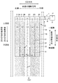
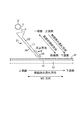
- FIG. 1 is a plan view of a first embodiment of a spraying device according to the present invention. It is a top view which shows the state after the change wall of FIG. 1 moved. It is a left view of FIG. It is a side view of 2nd Embodiment. The change wall on the other end side of the slope is shown in a floating state.
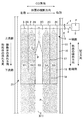
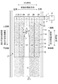
- FIG. 5 is a plan view of FIG. 4. It is a side view of 3rd Embodiment. The state after the change wall in the middle part of the slope surfaced is shown. It is a top view of a 3rd embodiment. The state before the change wall in the middle part of the slope rises is shown. It is a top view of a 4th embodiment. The change wall at the middle of the slope moves in the horizontal direction.
- FIG. 12 is a perspective view showing a state where the shutter of FIG. 11 is closed. It is a perspective view which shows the state which blows toward an inclined surface.
- diffusion apparatus 15 which concerns on this invention is an apparatus which spreads the granular material P on the moving body 10 which moves.
- SAP a kind of granular material P
- a moving lower layer sheet a kind of moving body 10
- the process after spraying SAP is described.
- the upper and lower sheets are sealed and cut at a predetermined interval.
- Get an SAP sheet in the manufacture of disposable diapers, when SAP is sprinkled on a pile of pulp fibers (a type of mobile body 10) placed on a moving back surface sheet (a type of mobile body 10) Can be used.
- the moving body 10 moves from the downstream side to the upstream side by the belt conveyor 11 or the like.
- A Configuration of spraying device 15 and related matters
- A Granule P
- An example of the powder P is a superabsorbent resin (SAP) used to absorb body fluid such as urine.
- SAP superabsorbent resin
- the powder P such as powder, particles, granules, and pellets, and any of them can be used in the present invention.
- Particulate materials are particularly suitable.
- the particle size of each particle of the granular material P is not particularly limited, but, for example, screening using a standard sieve (JIS Z8801-1: 2006) of 500 ⁇ m (shaking for 5 minutes), and dropping under the screen by this screening
- a standard sieve JIS Z8801-1: 2006
- the proportion of particles remaining on the 500 ⁇ m standard sieve was 30% by weight or less, and 180 ⁇ m It is desirable that the proportion of particles remaining on the standard sieve is 60% by weight or more.
- the weight of each particle of the granular material P is not particularly limited, but it is desirable to use, for example, one having a weight average of 0.2 to 10 mg.
- the spraying device 15 has a rectifying device 21.
- the rectifying device 21 is a device that is arranged above the moving body 10 and adjusts the flow of the powder particles P. In the first to fifth embodiments, it is arranged between the spray pipe 1 and the moving body 10.
- the rectifier 21 has a slope 16.
- the slope 16 is provided so as to be inclined with respect to the horizontal direction. This is for the powder P to roll down.
- the angle ⁇ between the horizontal plane and the slope 16 is not particularly limited, but is preferably 30 to 80 degrees, and more preferably 40 to 60 degrees.
- the angle is less than 30 degrees, the powder P hardly rolls down on the slope 16. Therefore, after the powder P is supplied to one end of the slope 16, it takes too much time to be discharged from the other end, and the amount of the powder P falling on the moving body 10 is reduced. End up.
- the granular material P rolls down on the slope 16 in an instant. In the process of rolling down, the change wall 18 is collided at high speed, and the powder P is scattered in all directions, making it difficult to control the flow of the powder P.
- the length of the slope 16 in the tilt direction is not particularly limited, but is preferably 8 cm to 40 cm, for example. Further, the length of the slope 16 in the transverse direction is not particularly limited, but is preferably 6 cm to 30 cm, for example.
- the material of the slope 16 can be, for example, steel or synthetic resin.
- the slope 16 is typically a flat plate, but other shape members such as a plate whose middle part is gently curved downward may be used.
- the rectifier 21 may be provided with a partition wall 17.
- the partition wall 17 extends along the slope of the slope 16 and partitions the slope 16 into a plurality of spaces.
- five spaces S are arranged in order from the left side to the right side of the slope 16. In this description, these spaces S are referred to as the first column space S1...
- the fifth column space S5 in order from the left side of FIG.
- the number of spaces S can be arbitrarily changed. For example, it can be 2 or more, and 2 to 10 is appropriate.
- the partition wall 17 may not be provided, and the number of spaces S in that case is one.
- the shape of the partition wall 17 is not limited to a linear shape, and can be changed to any known shape such as a curved shape. Further, the arrangement of the partition wall 17 is not limited to the form in which the partition wall 17 is arranged in parallel with the inclination direction of the slope 16, and the partition wall 17 may be arranged to be inclined so as to intersect the inclination direction.
- outer walls 22 are provided at both ends of the slope 16 in the transverse direction. The outer wall 22 prevents the powder P from spilling outward from the end.
- the granular material P is supplied to one end side of each space S from each spray hole 3 provided in the spray pipe 1. Specifically, a fixed amount of powder P is supplied from the spray holes 3 of the annular body 2A to the first row of spaces S1, and a fixed amount of powder is supplied from the spray holes 3 of the annular body 2B to the second row of spaces S2. The granular material P is supplied. Similarly, in the other rows, the space S3 in the third row from the spray holes 3 of the annular body 2C, the space S4 in the fourth row from the spray holes 3 in the annular body 2D, and the fifth row from the spray holes 3 in the annular body 2E. A certain amount of the granular material P is supplied to each of the spaces S5.
- the partition wall 17 By partitioning each space S with the partition wall 17, for example, the powder P supplied to the space S ⁇ b> 1 in the first row is prevented from moving to the adjacent space S ⁇ b> 2 beyond the partition wall 17. Therefore, the granular material P supplied to the space S1 in the first row rolls down the slope 16 from one end side to the other end side without moving to the space S2 in the second row, and the moving body 10 from the other end side. Fall on top. As described above, the partition wall 17 restricts diffusion of the slope 16 in the transverse direction in the process in which the granular material P rolls down the slope 16.
- the amount of the granular material P supplied to each space S from each spray hole 3 can be set to a different amount.
- the amount of the granular material P supplied to the first space S1, the second space S2, the fourth space S4, and the fifth space S5 is the same,
- the amount of the granular material P supplied to the space S3 in the third row is smaller than in the other rows. This is intended to reduce the amount of the granular material P sprayed on the central portion of the moving body 10 in the CD direction as compared with other portions.
- the partition wall 17 by providing the partition wall 17, the diffusion of the powder body P in the transverse direction of the slope 16 is limited. Therefore, when the partition wall 17 is provided, by changing the amount of the powder P supplied to each space S from each supply hole 3, the amount of spraying in the CD direction of the moving body 10 can be easily changed.
- the rectifier 21 has a change wall 18.
- the change wall 18 is provided on the slope 16.
- Examples of the target for fixing the change wall 18 include the slope 16 and the partition wall 17.
- As the fixing method a form in which a ring-shaped portion is provided on the change wall 18 and a fixing rod is inserted into the ring can be exemplified.
- Other known means may be used as the fixing object and fixing method of the change wall 18, but in any case, it is preferable to fix the change wall 18 so that it can move.
- An example of the change wall 18 is a single flat plate, but other known members may be used.
- a change wall 18 is provided at the other end of the slope 16 (FIG. 1). Specifically, the upper end portion of the change wall 18 is fixed to the lower end portion of the partition wall 17, and the change wall 18 is a part of the partition wall 17. Two change walls 18 are attached to one partition wall 17. In the movement of the change wall 18, the fixed portion on one end side of the change wall 18 serves as a fulcrum F, and the portions other than the fixed portion swing left and right.
- the change wall 18 moves to the left or right side of the slope 16 from the state of FIG. 2, the change wall 18 becomes an oblique wall that intersects the flow direction of the powder P (inclination direction of the slope 16) (FIG. 1). .
- the granular material P rolling down the slope 16 due to gravity hits the change wall 18 and changes its traveling direction. Specifically, the granular material P that collides with the change wall 18 moves along the inclination of the upper wall surface 18u of the change wall 18 and further rolls from the other end side end portion of the change wall 18 to the other end side of the slope 16. drop down.
- an area E (E1) in which the granular material P is not scattered in the CD direction of the moving body 10 is generated due to the influence of the change wall 18.
- the second embodiment is characterized in that the change wall 18 moves in the direction of rising from the slope 16.
- the two other change walls 18 adjacent to each other have a shape opened to the left and right so that the other end sides are separated from each other.
- the granular material P rolling down the slope 16 collides with the change wall 18 and changes its traveling direction.
- a region E (E1) where the powder particles P are not dispersed is formed.
- the surfacing change wall 18 can land on the slope 16.
- the region E (E1) is generated again.
- the region E ⁇ b> 1 can be intermittently formed in the MD direction of the moving body 10 by repeating the rising and landing of the change wall 18.
- the floating / landing movement of the change wall 18 can be realized, for example, by providing a rail (not shown) upward from the slope 16 and moving along the rail.
- the change wall 18 can be moved in the horizontal direction, as in the first embodiment. In this case, the effects of the first embodiment are also exhibited.
- the change wall 18 is provided in the intermediate part (between one end part and other end part) of the inclination direction of the slope 16 (FIG. 7).
- the change wall 18 has a mountain shape protruding toward one end side of the slope 16 in a plan view, and is disposed in the space S3 in the third row.
- the partition wall 17 In the vicinity of the intersection of the end of the change wall 18 and the partition wall 17 (position upstream of the intersection), there is a region B where the partition wall 17 does not exist. That is, the partition wall 17 extends linearly along the inclination direction of the slope 16, but a part of the partition wall 17 is interrupted, and the interrupted portion is a position immediately upstream of the end of the change wall 18. .
- the change wall 18 repeats floating and landing as in the second embodiment.
- the change wall 18 When the change wall 18 is positioned on the slope 16, the granular material P that has rolled down the space S ⁇ b> 3 in the third row collides with the change wall 18. A part of the granular material P rolls down to the adjacent left space (second row space S2), and the other rolls down to the adjacent right space (fourth row space S4). As a result, the amount of the granular material P that falls on the moving body 10 from the spaces S2 and S4 increases, and the granular material P does not fall on the moving body 10 from the space S3 (FIG. 7).
- the fourth embodiment is a modification of the third embodiment (FIG. 8). That is, a part of the partition wall 17 between the spaces S2 and S3 and a part of the partition wall 17 between the spaces S3 and S4 function as the change wall 18.
- the change wall 18 is movable in the transverse direction (left side or right side) of the slope 16.
- the granular material P is placed on the moving body 10 from the other end side of the spaces S2 and S4 as in FIG. 7 of the third embodiment. Although it falls, it does not fall from the other end side of the space S3.
- the change wall 18 is provided on one end side of the slope 16.
- the change wall 18 swings in the transverse direction of the slope 16. Even when the change wall 18 is provided on one end side of the slope 16, the spraying location and the spraying amount of the granular material P can be changed as in the first embodiment.
- the change wall 18 is preferably provided on the other end side rather than the one end side of the slope 16.
- the change wall 18 is provided on one end side of the slope 16, the flow of the granular material P is adjusted by the change wall 18, and then in the process of rolling down the slope 16, the change wall 18 is dispersed in the transverse direction of the slope 16. This is because the granular material P may not be sprayed on the intended location of the body 10. Therefore, the distance between the moving body 10 and the change wall 18 is preferably as close as possible.
- the length of the change wall 18 can be arbitrarily determined, a length that can form a state in which the granular material P does not fall from the space S when the change wall 18 moves to the left and right is preferable.
- the first embodiment (FIG. 1) will be described as an example.
- the change wall 18r1 located on the rightmost side in the transverse direction can form a state in which the granular material P does not fall from the space S5.
- the total length L (the length from one end to the other end) is preferably longer than the length W in the transverse direction of the space S5.
- the change wall 18r2 located on the left side of the change wall 18r1 can form a state in which the granular material P does not fall from the space S4, so that the total length L of the change wall 18 is the length in the transverse direction of the space S4. It is preferable to make it longer than 1/2 of the length W. Unlike the change wall 18 of the space S5, the reason why the length is 1 ⁇ 2 is that there is another change wall 18r3 on the left side of the space S4, and the other change wall 18r3 corresponds to the remaining 1 ⁇ 2 length. This is because the area can be blocked. In the form of FIG. 1, the lengths of the change walls 18 are all the same, but may be different lengths. At this time, it is preferable that the total length of the left and right change walls 18r3 and 18r2 in the space S4 is longer than the length W in the transverse direction of the space S4.
- the change wall 18 in both the left and right sides rather than providing only in either the left side or the right side of each space S.
- the first embodiment (FIG. 1) will be described as an example.
- the change wall 18r1 is on the left side of the space S5
- the change wall 18 is not present on the right side (on the extended line of the outer wall 22). Therefore, when the change wall 18r1 is moved slightly to the right side, the granular material P does not fall on the moving body 10 from the left side portion of the space S5, and an area E (E1) where the granular material P does not exist on the left side portion. It is formed.
- the granular material P falls on the moving body 10 from the right side portion of the space S5, and an area where the granular material P exists is formed. And if the said change wall 18r1 is further moved to the right side and is made to contact
- the change wall 18 does not exist on the right side of the space S5
- the region E1 is formed on the moving body 10 corresponding to the right side of the space S5
- the powder particles are formed on the moving body 10 corresponding to the left side of the space S5.
- a region where the body P exists cannot be formed.
- the spraying device 15 may be provided with the spraying tube 1.
- the spray tube 1 is used for spraying the powder P.
- the spray pipe 1 for example, a single straight pipe made of steel can be used.
- the spray tube 1 may have an annular body 2.
- the position where the annular body 2 is disposed is preferably a portion facing the moving body 10. This is because the granular material P is sprayed from the spraying holes 3 provided in the annular body 2.
- the movable body 10 on the distal end side of the spray tube 1. It is preferable to arrange the annular body 2 at a position facing the.
- the annular body 2 is provided with a spray hole 3.
- the number of spray holes 3 can be arbitrarily determined. For example, when there are five spaces (S1 to S5) as shown in FIG. 1, it is preferable to provide the spray holes 3 corresponding to the respective spaces. This is because the granular material P is dispersed in each space.
- Transporter A transporter (not shown) that transports the granular material P can be provided inside the spray tube 1.
- this transporter one steel material wound in a spiral shape can be cited.
- a screw or the like may be used.
- (F) Cover 19 Since the granular material P is light, it may be scattered when rolling down the slope 16. Therefore, it is preferable to provide the rectifier 21 with a cover 19 for preventing scattering. In the example shown in FIG. 11, the cover 19 is provided above the rectifying device 21 so as to straddle the outer wall 22 and the partition wall 17.
- a shutter 20 can also be provided at the other end of the rectifier 21 (FIGS. 11 and 12). By opening and closing the shutter 20, the powder particles P can be intermittently dispersed in the MD direction of the moving body 10.
- the blower device 15 may be provided with a blower device (not shown). By blowing air A with this blower, the speed of the granular material P flowing on the slope 16 can be increased, and even when the moving body 10 moves at a high speed, the granular material P is surely secured. Can be sprayed on.
- the spraying device 15 can be provided with a hopper 5 that temporarily stores the powder P supplied to the spraying tube 1, a support member that supports the spraying tube 1, and the like. Since these are not the main parts of the present invention, detailed description is omitted.
- a hopper 5 that temporarily stores the powder P supplied to the spraying tube 1, a support member that supports the spraying tube 1, and the like. Since these are not the main parts of the present invention, detailed description is omitted.
- the bulge may not be given with emphasis on ease of manufacturing (FIG. 10).
Landscapes
- Chemical & Material Sciences (AREA)
- Life Sciences & Earth Sciences (AREA)
- Engineering & Computer Science (AREA)
- Wood Science & Technology (AREA)
- Organic Chemistry (AREA)
- Chemical Kinetics & Catalysis (AREA)
- Absorbent Articles And Supports Therefor (AREA)
- Application Of Or Painting With Fluid Materials (AREA)
- Coating Apparatus (AREA)
- Feeding, Discharge, Calcimining, Fusing, And Gas-Generation Devices (AREA)
- Fertilizing (AREA)
Abstract
【課題】時間によって粉粒体を散布する場所や量を変えることができる粉粒体の散布装置および散布方法を提供することにある。 【解決手段】移動体(10)の上に粉粒体(P)を散布する散布装置(15)であって、前記散布装置(15)は、前記移動体(10)の上方に配置した整流装置(21)を有し、前記整流装置(21)は、一端側から他端側へ向って下り勾配の斜面(16)と、前記斜面(16)に設けられ、前記粉粒体(P)の流れる方向を変える可動式の変更壁(18)と、を有し、前記粉粒体(P)を前記斜面(16)の一端側に供給し、その粉粒体(P)が前記斜面(16)を転がり落ちる過程で、前記変更壁(18)と衝突してその進行方向を変え、前記斜面(16)の他端側から前記移動体(10)上に落下する構成である散布装置を提供する。
Description
本発明は、一定方向に流れるシート上に粉粒体を散布する方法および散布する装置に関する。
従来の粉粒体の散布装置は、外部から供給された粉粒体を一時的に貯留するホッパーと、前記ホッパーの側壁から外方へ向かって延在する散布管と、前記散布管内に配置され、ホッパー内の粉粒体を散布管の先端部へ向かって送り出すスクリューを有する。スクリューによって送り出された粉粒体は、散布管の先端から落下し、散布管の下方を流れるシート上に散布される。
このとき、散布管に設けられた粉粒体の出口は一カ所(散布管の先端)であるため、下方を流れるシートのうち、散布管の直下部分には、粉粒体が多く散布されるが、その周辺部分には粉粒体の散布量が少なくなるという問題があった。すなわち、シートの流れ方向と交差する方向(Cross Direction方向、CD方向)に粉粒体を均一に散布することができないという問題があった。特に、2枚の不織布の間隙に高吸収性樹脂(Super Absorbent Polymer、SAP)を挟み込んだシート(SAPシート)を製造する際には、CD方向に散布する量をより細かく制御する必要があり、現状の設備においては、そのような制御ができていないという問題があった。
粉粒体の散布方法や散布装置に関連する先行技術文献としては、下記特許文献1および2がある。
下記特許文献1に係る複合シートの製造方法は、複数の滑落板を上下方向に互い違いとなるように配置し、液体吸収性粒状物(以下、「粒状物」という。)が、滑落板に沿って、その上を反転しながら滑落し、滑落板の下方を流れる表面シートの上に落下する構成となっている。そして、この滑落板に案内溝やガイド部材を設けることで、シートの幅方向の目的部分(凹部)にのみ粉粒体を供給し、その他の部分に粉粒体を供給しないようにすることができる旨が開示されている。
下記特許文献1に係る複合シートの製造方法は、複数の滑落板を上下方向に互い違いとなるように配置し、液体吸収性粒状物(以下、「粒状物」という。)が、滑落板に沿って、その上を反転しながら滑落し、滑落板の下方を流れる表面シートの上に落下する構成となっている。そして、この滑落板に案内溝やガイド部材を設けることで、シートの幅方向の目的部分(凹部)にのみ粉粒体を供給し、その他の部分に粉粒体を供給しないようにすることができる旨が開示されている。
下記特許文献2に係る粉粒体の散布方法は、散布管の両端部下方に矯正ガイドが設けられ、当該ガイドが基材を横断する方向に搖動する構成となっている。そして、この搖動によって、粉粒体の散布幅を広げたり、狭めたりすることを可能にしている。
しかし、前記特許文献1に係る製造方法は、各凹部に供給する粒状物の量を時間によって変更したり、粒状物の供給場所を時間によって変更したりすることができない。また、前記特許文献2に係る散布方法は、粉粒体の供給量を時間によって変更することはできるが、散布場所を幅方向全体に供給するか、中央部に供給するかの二者択一しかできない。したがって、前記特許文献1および2は、製造時に粉粒体の散布の細かな制御が求められる製品の製造に適さないという問題があった。
そこで、本発明の主たる課題は、時間によって粉粒体を散布する場所や量を変えることができる粉粒体の散布方法および散布装置を提供することにある。
上記課題を解決した本発明は次記のとおりである。
(1)移動体の上に粉粒体を散布する散布装置であって、
前記散布装置は、前記移動体の上方に配置した整流装置を有し、
前記整流装置は、
一端側から他端側へ向って下り勾配の斜面と、
前記斜面に設けられ、前記粉粒体の流れる方向を変える可動式の変更壁と、を有し、
前記粉粒体を前記斜面の一端側に供給し、その粉粒体が前記斜面を転がり落ちる過程で、前記変更壁と衝突してその進行方向を変え、前記斜面の他端側から前記移動体上に落下する構成であることを特徴とする散布装置。
(1)移動体の上に粉粒体を散布する散布装置であって、
前記散布装置は、前記移動体の上方に配置した整流装置を有し、
前記整流装置は、
一端側から他端側へ向って下り勾配の斜面と、
前記斜面に設けられ、前記粉粒体の流れる方向を変える可動式の変更壁と、を有し、
前記粉粒体を前記斜面の一端側に供給し、その粉粒体が前記斜面を転がり落ちる過程で、前記変更壁と衝突してその進行方向を変え、前記斜面の他端側から前記移動体上に落下する構成であることを特徴とする散布装置。
(作用効果)
粉粒体は、斜面の傾斜に沿って、斜面の一端側から他端側へ向かって転がり落ちる。したがって、例えば、斜面に変更壁を設けず、かつ、斜面を横断する方向に粉粒体を均等に供給したときは、粉粒体はその進行方向を特段変更することなく、斜面をそのまま転がり落ちる。他端側まで転がり落ちた粉粒体は、斜面から移動体の上へ落下する。移動体の上に落下する粉粒体の量は、斜面の横断方向においてほぼ均等となる。
粉粒体は、斜面の傾斜に沿って、斜面の一端側から他端側へ向かって転がり落ちる。したがって、例えば、斜面に変更壁を設けず、かつ、斜面を横断する方向に粉粒体を均等に供給したときは、粉粒体はその進行方向を特段変更することなく、斜面をそのまま転がり落ちる。他端側まで転がり落ちた粉粒体は、斜面から移動体の上へ落下する。移動体の上に落下する粉粒体の量は、斜面の横断方向においてほぼ均等となる。
本発明に係る散布装置は、斜面の上に変更壁を有している。粉粒体は、斜面を転がり落ちる過程で変更壁と衝突し、変更壁に誘導されて進行方向を変えた後、斜面の他端側から移動体の上に落下する。したがって、移動体の上に落下する粉粒体の量を、斜面の横断方向において、任意に変えることができる。移動体の一部に粉粒体を散布しないことも可能となる。さらに、変更壁を可動式とすることで、粉粒体の散布量や散布位置を時間によって変えることができる。
(2)前記変更壁は、前記斜面を横方向に移動する前記(1)記載の散布装置。
(作用効果)
変更壁が斜面を横方向へ移動すると、粉粒体が変更壁に誘導されて進行する方向が時間によって変わる。したがって、斜面を横断する方向において、移動体の上に落下する粉粒体の量を時間によって変えることができる。また、移動体の上に粉粒体が落下しない箇所を時間によって変えることもできる。
変更壁が斜面を横方向へ移動すると、粉粒体が変更壁に誘導されて進行する方向が時間によって変わる。したがって、斜面を横断する方向において、移動体の上に落下する粉粒体の量を時間によって変えることができる。また、移動体の上に粉粒体が落下しない箇所を時間によって変えることもできる。
さらに、変更壁の一部分を横方向へ移動し、変更壁の延在方向と斜面の傾斜方向を一致させることもできる。このように一致させた場合、粉粒体は進行方向を特段変更することなく、斜面をそのまま転げ落ち、前記(1)の作用効果が生じない。その状態から、変更壁の一部分を横方向へ移動した場合は、粉粒体が再び変更壁と衝突するようになり、前記(1)の作用効果を再び奏するようになる。本形態では、このような切り替えを行うことも可能である。
(3)前記変更壁は、前記斜面から浮上する前記(1)または(2)記載の散布装置。
(作用効果)
変更壁が斜面の上にあるときは、粉粒体が変更壁と衝突し、その進行方向を変えるため、前記(1)と同様の作用効果を奏する。反対に、変更壁が斜面から浮上したときは、粉粒体はその進行方向を特段変更することなく、斜面をそのまま転がり落ちるため、前記(1)の作用効果を奏しない。本形態では、このような切り替えを行うことができる。
変更壁が斜面の上にあるときは、粉粒体が変更壁と衝突し、その進行方向を変えるため、前記(1)と同様の作用効果を奏する。反対に、変更壁が斜面から浮上したときは、粉粒体はその進行方向を特段変更することなく、斜面をそのまま転がり落ちるため、前記(1)の作用効果を奏しない。本形態では、このような切り替えを行うことができる。
(4)前記整流装置は、
前記斜面の傾斜に沿って延在し、前記斜面を複数の空間に仕切る仕切壁をさらに有する前記(1)記載の散布装置。
前記斜面の傾斜に沿って延在し、前記斜面を複数の空間に仕切る仕切壁をさらに有する前記(1)記載の散布装置。
(作用効果)
斜面を転がり落ちる粉粒体が、仕切壁を越えて隣の空間へ移動することを防ぐことができる。
斜面を転がり落ちる粉粒体が、仕切壁を越えて隣の空間へ移動することを防ぐことができる。
(5)前記変更壁は、前記仕切壁の一部を構成する前記(4)記載の散布装置。
(作用効果)
変更壁が仕切壁の一部を構成しない場合と比べて、整流装置の構造がシンプルになる。整流装置の価格を下げることができるとともに、メンテナンス性が向上する。
変更壁が仕切壁の一部を構成しない場合と比べて、整流装置の構造がシンプルになる。整流装置の価格を下げることができるとともに、メンテナンス性が向上する。
(6)前記整流装置は、
前記粉粒体の飛散を防止するカバーをさらに有する前記(1)記載の散布装置。
前記粉粒体の飛散を防止するカバーをさらに有する前記(1)記載の散布装置。
(作用効果)
粉粒体が斜面を転がり落ちるときや、粉粒体が変更壁と衝突したときの粉粒体の飛散を防止できる。
粉粒体が斜面を転がり落ちるときや、粉粒体が変更壁と衝突したときの粉粒体の飛散を防止できる。
(7)前記整流装置は、
前記斜面の他端側にシャッターをさらに有する前記(1)記載の散布装置。
前記斜面の他端側にシャッターをさらに有する前記(1)記載の散布装置。
(作用効果)
シャッターを開けると、粉粒体が移動体の上に落下するが、シャッターを閉めると、落下しなくなる。このシャッターの開閉を繰り返すことで、粉粒体を間欠散布できる。
シャッターを開けると、粉粒体が移動体の上に落下するが、シャッターを閉めると、落下しなくなる。このシャッターの開閉を繰り返すことで、粉粒体を間欠散布できる。
(8)前記散布装置は、
前記斜面の一端側から他端側へ向かって送風する送風装置を有する前記(1)記載の散布装置。
前記斜面の一端側から他端側へ向かって送風する送風装置を有する前記(1)記載の散布装置。
(作用効果)
移動体が高速で移動すると、移動体の上に載る粉粒体の量が少なくなる。送風装置を用いて、一端側から他端側に送風することで、粉粒体が斜面を転がり落ちる速度が速くなるため、移動体の上に載る粉粒体の量を増やすことができる。
移動体が高速で移動すると、移動体の上に載る粉粒体の量が少なくなる。送風装置を用いて、一端側から他端側に送風することで、粉粒体が斜面を転がり落ちる速度が速くなるため、移動体の上に載る粉粒体の量を増やすことができる。
(9)整流装置を用いて、移動体の上に粉粒体を散布する散布方法であって、
前記整流装置は、前記移動体の上方に配置され、
一端側から他端側へ向って下り勾配の斜面と、
前記斜面の上に設けられ、前記粉粒体の流れる方向を変える可動式の変更壁と、を有し、
前記粉粒体を前記斜面の一端側に供給し、その粉粒体が前記斜面を転がり落ちる過程で、前記変更壁と衝突してその進行方向を変え、前記斜面の他端側から前記移動体上に落下することを特徴とする散布方法。
前記整流装置は、前記移動体の上方に配置され、
一端側から他端側へ向って下り勾配の斜面と、
前記斜面の上に設けられ、前記粉粒体の流れる方向を変える可動式の変更壁と、を有し、
前記粉粒体を前記斜面の一端側に供給し、その粉粒体が前記斜面を転がり落ちる過程で、前記変更壁と衝突してその進行方向を変え、前記斜面の他端側から前記移動体上に落下することを特徴とする散布方法。
以上のとおり本発明に係る散布装置および散布方法によれば、時間によって粉粒体を散布する場所や量を変えることができる。
(散布装置の用途)
本発明に係る散布装置15は、移動する移動体10の上に粉粒体Pを散布する装置である。
例えば、SAPシートの製造において、移動する下層シート(移動体10の一種)の上にSAP(粉粒体Pの一種)を散布する際に用いる。参考までに、SAPを散布した後の工程について述べると、粉粒体Pが載った下層シートの上に上層シートを重ね合わせ、上層と下層のシートをシールし、所定の間隔で切断することにより、SAPシートを得る。
その他の例としては、使い捨ておむつの製造において、移動する裏面側シート(移動体10の一種)の上に載せたパルプ繊維(移動体10の一種)の積繊体にSAPを散布する際にも用いることができる。
なお、前記移動体10は、ベルトコンベア11などによって下流側から上流側へ移動する。
本発明に係る散布装置15は、移動する移動体10の上に粉粒体Pを散布する装置である。
例えば、SAPシートの製造において、移動する下層シート(移動体10の一種)の上にSAP(粉粒体Pの一種)を散布する際に用いる。参考までに、SAPを散布した後の工程について述べると、粉粒体Pが載った下層シートの上に上層シートを重ね合わせ、上層と下層のシートをシールし、所定の間隔で切断することにより、SAPシートを得る。
その他の例としては、使い捨ておむつの製造において、移動する裏面側シート(移動体10の一種)の上に載せたパルプ繊維(移動体10の一種)の積繊体にSAPを散布する際にも用いることができる。
なお、前記移動体10は、ベルトコンベア11などによって下流側から上流側へ移動する。
(説明の進め方)
以下に本発明の詳細を説明する。
まず、(1)散布装置15の構成と関連事項を説明する。具体的には、(A)粉粒体P、(B)斜面16、(C)仕切壁17、(D)変更壁18、(E)散布管1(環状体2、散布孔3、輸送体)、(F)カバー19、(G)シャッター20、(H)送風装置、(I)その他の順序で説明する。
次に、(2)散布方法について説明する。具体的には、(J)粉粒体Pを散布する際の基本的なフロー、(K)粉粒体Pの散布量を調整する際のフローの順序で説明する。
以下に本発明の詳細を説明する。
まず、(1)散布装置15の構成と関連事項を説明する。具体的には、(A)粉粒体P、(B)斜面16、(C)仕切壁17、(D)変更壁18、(E)散布管1(環状体2、散布孔3、輸送体)、(F)カバー19、(G)シャッター20、(H)送風装置、(I)その他の順序で説明する。
次に、(2)散布方法について説明する。具体的には、(J)粉粒体Pを散布する際の基本的なフロー、(K)粉粒体Pの散布量を調整する際のフローの順序で説明する。
(1)散布装置15の構成と関連事項
(A)粉粒体P
粉粒体Pとしては、尿などの体液を吸収するために用いる高吸収性樹脂(SAP)を例示できる。
この粉粒体Pの形状は、粉体状、粒子状、顆粒状、ペレット状等のさまざまな形態のものがあり、いずれも本発明において使用可能である。特に、粒子状のものが好適である。
(A)粉粒体P
粉粒体Pとしては、尿などの体液を吸収するために用いる高吸収性樹脂(SAP)を例示できる。
この粉粒体Pの形状は、粉体状、粒子状、顆粒状、ペレット状等のさまざまな形態のものがあり、いずれも本発明において使用可能である。特に、粒子状のものが好適である。
粉粒体Pの各粒子の粒径は特に限定されないが、例えば500μmの標準ふるい(JIS Z8801-1:2006)を用いたふるい分け(5分間の振とう)、及びこのふるい分けでふるい下に落下する粒子について180μmの標準ふるい(JIS Z8801-1:2006)を用いたふるい分け(5分間の振とう)を行ったときに、500μmの標準ふるい上に残る粒子の割合が30重量%以下で、180μmの標準ふるい上に残る粒子の割合が60重量%以上のものが望ましい。
また、粉粒体Pの各粒子の重量も特に限定されないが、例えば重量平均が0.2~10mgのものを用いることが望ましい。
(B)斜面16
散布装置15は、整流装置21を有する。この整流装置21は、移動体10の上方に配置され、粉粒体Pの流れを整える装置である。第1~第5実施形態においては、散布管1と移動体10の中間に配置している。
散布装置15は、整流装置21を有する。この整流装置21は、移動体10の上方に配置され、粉粒体Pの流れを整える装置である。第1~第5実施形態においては、散布管1と移動体10の中間に配置している。
この整流装置21は、斜面16を備えている。この斜面16は、水平方向に対して斜めになるように設けている。粉粒体Pが転がり落ちるようにするためである。
水平面と斜面16の間の角度αは(図3)、特に限定されないが、30度~80度にすることが好ましく、40度~60度にすることがより好ましい。30度より小さいと、粉粒体Pが斜面16の上を転がり落ちにくい。そのため、粉粒体Pが斜面16の一端側に供給された後、他端側から排出されるまでに時間がかかりすぎて、移動体10の上に落下する粉粒体Pの量が少なくなってしまう。他方、80度より大きいと、粉粒体Pが斜面16の上を一瞬で転がり落ちてしまう。転がり落ちる過程で、変更壁18に高速で衝突することとなり、粉粒体Pが四方八方に飛散し、粉粒体Pの流れの制御が困難になる。
斜面16の傾斜方向の長さは、特に限定されないが、例えば8cm~40cmにすることが好ましい。また、斜面16の横断方向の長さも特に限定されないが、例えば6cm~30cmにすることが好ましい。
斜面16の材質は、例えば鉄鋼、合成樹脂などを用いることができる。また、斜面16としては平板が代表的であるが、中間部が下方へ向かって緩やかに湾曲している板など、他の形状の部材を用いても良い。
(C)仕切壁17
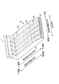
整流装置21には、仕切壁17を設けても良い。この仕切壁17は、斜面16の傾斜に沿って延在し、斜面16を複数の空間に仕切っている。第1~第5実施形態では、4個の仕切壁17があり、各仕切壁17を並列に配置している。前記複数の仕切壁17により、斜面16の左側から右側へ向かって順に空間Sが5個並んでいる。本説明では、これらの空間Sを図1の左側から順に1列目の空間S1・・・5列目の空間S5と呼ぶ。
整流装置21には、仕切壁17を設けても良い。この仕切壁17は、斜面16の傾斜に沿って延在し、斜面16を複数の空間に仕切っている。第1~第5実施形態では、4個の仕切壁17があり、各仕切壁17を並列に配置している。前記複数の仕切壁17により、斜面16の左側から右側へ向かって順に空間Sが5個並んでいる。本説明では、これらの空間Sを図1の左側から順に1列目の空間S1・・・5列目の空間S5と呼ぶ。
なお、空間Sの数は任意に変更することができる。例えば、2個以上にすることができ、2個~10個程度が妥当である。仕切壁17を設けないようにしても良く、その場合の空間Sの数は1個となる。
仕切壁17の形状は、直線形に限られず、曲線形等の任意の公知形状に変更することができる。また、仕切壁17の配置は、斜面16の傾斜方向と平行に配置する形態に限られず、当該傾斜方向と交差するように傾けて配置しても良い。
仕切壁17の形状は、直線形に限られず、曲線形等の任意の公知形状に変更することができる。また、仕切壁17の配置は、斜面16の傾斜方向と平行に配置する形態に限られず、当該傾斜方向と交差するように傾けて配置しても良い。
なお、斜面16の横断方向の両端部には、外壁22が設けられている。粉粒体Pが前記端部から外方へこぼれ落ちることをこの外壁22で防いでいる。
第1~第5実施形態では、散布管1に設けた各散布孔3から各空間Sの一端側にそれぞれ粉粒体Pを供給している。具体的には、環状体2Aの散布孔3から1列目の空間S1に一定量の粉粒体Pを供給し、環状体2Bの散布孔3から2列目の空間S2に一定量の粉粒体Pを供給している。その他の列も同様に、環状体2Cの散布孔3から3列目の空間S3に、環状体2Dの散布孔3から4列目の空間S4に、環状体2Eの散布孔3から5列目の空間S5に、それぞれ一定量の粉粒体Pを供給している。各空間Sを仕切壁17で仕切ることにより、例えば1列目の空間S1に供給した粉粒体Pが、仕切壁17を越えて隣接する列の空間S2に移動することを防いでいる。したがって、1列目の空間S1に供給された粉粒体Pは、2列目の空間S2に移動することなく、斜面16を一端側から他端側へ転げ落ち、他端側から移動体10の上に落下する。以上のように仕切壁17は、粉粒体Pが斜面16を転げ落ちる過程で、斜面16の横断方向への拡散を制限している。
各散布孔3から各空間Sに供給する粉粒体Pの量は、それぞれ異なる量にすることができる。第1~第5実施形態では、1列目の空間S1、2列目の空間S2、4列目の空間S4、5列目の空間S5に供給する粉粒体Pの量を同量とし、3列目の空間S3に供給する粉粒体Pの量を他の列よりも少なくしている。これは、移動体10のCD方向中央部分に散布する粉粒体Pの量を他の部分よりも少なくすることを狙ったものである。前記のとおり、仕切壁17を設けることにより、斜面16の横断方向に粉粒体Pが拡散することが制限される。そのため、仕切り壁17を設けると、各供給孔3から各空間Sに供給する粉粒体Pの量を変えることで、移動体10のCD方向の散布量を容易に変えることができる。
(D)変更壁18
整流装置21は変更壁18を有する。この変更壁18は斜面16の上に設けられている。変更壁18を固定する対象は、斜面16や仕切壁17などを例示できる。固定方法は、変更壁18にリング状の部分を設け、そのリング内に固定棒を差し込む形態を例示することができる。変更壁18の固定対象や固定方法は、その他の公知手段を用いてもよいが、いずれにしても変更壁18が移動できるように固定することが好ましい。なお、変更壁18の例としては1枚の平板を挙げることができるが、その他の公知部材を用いても良い。
整流装置21は変更壁18を有する。この変更壁18は斜面16の上に設けられている。変更壁18を固定する対象は、斜面16や仕切壁17などを例示できる。固定方法は、変更壁18にリング状の部分を設け、そのリング内に固定棒を差し込む形態を例示することができる。変更壁18の固定対象や固定方法は、その他の公知手段を用いてもよいが、いずれにしても変更壁18が移動できるように固定することが好ましい。なお、変更壁18の例としては1枚の平板を挙げることができるが、その他の公知部材を用いても良い。
(第1実施形態)
第1実施形態では、斜面16の他端側端部に変更壁18を設けている(図1)。詳しくは、仕切壁17の下端部に変更壁18の上端部を固定し、変更壁18が仕切壁17の一部となっている。変更壁18の数は、1つの仕切壁17に対して、2つずつ取り付けられている。この変更壁18の動きは、変更壁18の一端側の固定部が支点Fとなって、固定部以外の部分が左右に揺れ動く。
第1実施形態では、斜面16の他端側端部に変更壁18を設けている(図1)。詳しくは、仕切壁17の下端部に変更壁18の上端部を固定し、変更壁18が仕切壁17の一部となっている。変更壁18の数は、1つの仕切壁17に対して、2つずつ取り付けられている。この変更壁18の動きは、変更壁18の一端側の固定部が支点Fとなって、固定部以外の部分が左右に揺れ動く。
2個の変更壁18が仕切壁17の延長線上に位置する状態では、粉粒体Pは変更壁18によって進行方向を変えることなく、そのまま移動体10の上に流れ落ちる(図2)。すなわち、変更壁18が原因となってCD方向に粉粒体Pが散布されない領域Eが生じる、ということがない。なお、図2においても、粉粒体Pの散布されていない領域E2が存在するが、これは3列目の空間S3に供給する粉粒体Pの量が少ないことによるものであり、変更壁18の影響によるものではない。
図2の状態から、変更壁18が斜面16の左側または右側に動くと、変更壁18は粉粒体Pの流れ方向(斜面16の傾斜方向)と交差する斜めの壁となる(図1)。重力によって、斜面16を転がり落ちる粉粒体Pは、変更壁18にぶつかり、その進行方向を変える。詳しくは、変更壁18とぶつかった粉粒体Pは、変更壁18の上壁面18uをその傾斜に沿って移動し、変更壁18の他端側端部から斜面16の他端側へさらに転がり落ちる。このように、変更壁18が動いて斜め方向に傾くと、変更壁18の影響により、移動体10のCD方向に粉粒体Pの散布されない領域E(E1)が生じる。また、変更壁18に沿って移動した粉粒体Pの影響により、移動体10のCD方向に粉粒体Pの散布量が多い領域が生じる。この散布量が多い領域は、変更壁18の他端側端部を斜面16の傾斜に沿って他端側へ延長した位置に生じる。
(第2実施形態)
第2実施形態は、変更壁18が斜面16から浮上する方向に移動することを特徴とする。
本実施形態は、図1と同様に、隣接する2つの変更壁18の他端側が互いに離れるように左右に開いた形状をしている。変更壁18が斜面16と接している(変更壁18が斜面16上に位置する)状態では、斜面16を転がり落ちる粉粒体Pは、変更壁18に衝突してその進行方向を変えるため、移動体10のCD方向において、粉粒体Pが散布されていない領域E(E1)を形成する。
第2実施形態は、変更壁18が斜面16から浮上する方向に移動することを特徴とする。
本実施形態は、図1と同様に、隣接する2つの変更壁18の他端側が互いに離れるように左右に開いた形状をしている。変更壁18が斜面16と接している(変更壁18が斜面16上に位置する)状態では、斜面16を転がり落ちる粉粒体Pは、変更壁18に衝突してその進行方向を変えるため、移動体10のCD方向において、粉粒体Pが散布されていない領域E(E1)を形成する。
他方、変更壁18が斜面16から浮き上がると(図4)、粉粒体Pが変更壁18と衝突せずに、斜面16をそのまま転がり落ちるようになる。結果として、前記領域E(E1)が生じない(図5)。
浮上した変更壁18は、斜面16の上に着地することができる。変更壁18が斜面16の上に戻ると、前記領域E(E1)が再び生じる。本発明では、変更壁18の浮上と着地を繰り返すことで、前記領域E1を移動体10のMD方向に間欠的に形成することができる。なお、変更壁18の浮上・着地の移動は、例えば斜面16から上方へ向かってレール(図示しない)を設け、そのレールに沿って動かすことにより実現できる。
第2実施形態においても、第1実施形態と同様に、変更壁18を横方向へ動かすこともできる。この場合は、第1実施形態の作用効果も奏することになる。
(第3実施形態)
第3実施形態では、斜面16の傾斜方向の中間部(一端部と他端部の間)に変更壁18を設けている(図7)。この変更壁18は、平面視で、斜面16の一端側へ向かって突出する山形形状であり、3列目の空間S3に配置されている。
第3実施形態では、斜面16の傾斜方向の中間部(一端部と他端部の間)に変更壁18を設けている(図7)。この変更壁18は、平面視で、斜面16の一端側へ向かって突出する山形形状であり、3列目の空間S3に配置されている。
変更壁18の端部と仕切壁17の交点の近傍(交点より上流側の位置)には、仕切壁17の存在しない領域Bがある。すなわち、斜面16の傾斜方向に沿って仕切壁17が直線状に延在しているが、その一部分が途切れており、その途切れた箇所が変更壁18の端部のすぐ上流側の位置である。
変更壁18は、第2実施形態と同様に、浮上と着地を繰り返す。
変更壁18が斜面16上に位置するときは、3列目の空間S3を転がり落ちてきた粉粒体Pが変更壁18と衝突する。そして、粉粒体Pの一部は、隣接する左側の空間(2列目の空間S2)へ転がり落ち、その他は隣接する右側の空間(4列目の空間S4)へ転がり落ちる。その結果、空間S2とS4から移動体10上に落下する粉粒体Pの量が多くなり、空間S3から移動体10上には粉粒体Pが落下しなくなる(図7)。
変更壁18が斜面16上に位置するときは、3列目の空間S3を転がり落ちてきた粉粒体Pが変更壁18と衝突する。そして、粉粒体Pの一部は、隣接する左側の空間(2列目の空間S2)へ転がり落ち、その他は隣接する右側の空間(4列目の空間S4)へ転がり落ちる。その結果、空間S2とS4から移動体10上に落下する粉粒体Pの量が多くなり、空間S3から移動体10上には粉粒体Pが落下しなくなる(図7)。
変更壁18が斜面16から浮上したときは、粉粒体Pが変更壁18と衝突しない。そのため、粉粒体Pは図2と同様に散布される。
(第4実施形態)
第4実施形態は、第3実施形態の変形例である(図8)。すなわち、空間S2とS3の間の仕切り壁17の一部分、および空間S3とS4の間の仕切壁17の一部分が、変更壁18として機能する。この変更壁18は、斜面16の横断方向(左側または右側)に移動可能となっている。2つの変更壁18が空間S3上で重なり合った状態(図8)では、第3実施例の図7と同様に、粉粒体Pは空間S2、S4の他端側から移動体10の上に落下するが、空間S3の他端側からは落下しない。
第4実施形態は、第3実施形態の変形例である(図8)。すなわち、空間S2とS3の間の仕切り壁17の一部分、および空間S3とS4の間の仕切壁17の一部分が、変更壁18として機能する。この変更壁18は、斜面16の横断方向(左側または右側)に移動可能となっている。2つの変更壁18が空間S3上で重なり合った状態(図8)では、第3実施例の図7と同様に、粉粒体Pは空間S2、S4の他端側から移動体10の上に落下するが、空間S3の他端側からは落下しない。
図8の状態から、2つの変更壁18が互いに離れるように動き、重なり状態が解除されると、空間S3の他端側からも粉粒体Pが落下するようになる。
また、変更壁18が空間S2内に移動した場合は、空間S2を流れる粉粒体Pの一部(もしくは全部)が空間S3へ移動するようになる。その結果、空間S2から移動体10の上に落下する粉粒体Pの量が少なくなり(もしくは空間S2から粉粒体Pが落下しなくなり)、空間S3から落下する粉粒体Pの量が多くなる。変更壁18が空間S4内に移動したときも、同様の現象が生じる。
また、変更壁18が空間S2内に移動した場合は、空間S2を流れる粉粒体Pの一部(もしくは全部)が空間S3へ移動するようになる。その結果、空間S2から移動体10の上に落下する粉粒体Pの量が少なくなり(もしくは空間S2から粉粒体Pが落下しなくなり)、空間S3から落下する粉粒体Pの量が多くなる。変更壁18が空間S4内に移動したときも、同様の現象が生じる。
また、仕切壁17と変更壁18が一直線状に位置しているときは、変更壁18によって粉粒体Pの流れが変わることがない。したがって、粉粒体Pは図2と同様に散布される。
(第5実施形態)
第5実施形態では、斜面16の一端側に変更壁18を設けた例である。この変更壁18は、斜面16の横断方向に搖動する。斜面16の一端側に変更壁18を設けた場合も、第1実施例と同様に、粉粒体Pの散布場所や散布量を変更することができる。
第5実施形態では、斜面16の一端側に変更壁18を設けた例である。この変更壁18は、斜面16の横断方向に搖動する。斜面16の一端側に変更壁18を設けた場合も、第1実施例と同様に、粉粒体Pの散布場所や散布量を変更することができる。
なお、変更壁18は、斜面16の一端側よりも他端側に設けるほうが好ましい。変更壁18を斜面16の一端側に設けた場合、変更壁18によって粉粒体Pの流れが整えられた後、斜面16を転がり落ちる過程で、斜面16の横断方向に分散してしまい、移動体10の狙い通りの場所に粉粒体Pを散布できないことがあるからである。したがって、移動体10と変更壁18の間の距離は、出来る限り近くすることが好ましい。
(その他)
変更壁18の長さは任意に決めることができるが、変更壁18が左右に動いたときに、空間Sから粉粒体Pが落下しない状態を形成できる長さが好適である。第1実施形態(図1)を例に説明すると、横断方向の最も右側に位置する変更壁18r1は、空間S5から粉粒体Pが落下しない状態を形成できるようにするため、変更壁18の全長L(一端から他端までの長さ)を空間S5の横断方向の長さWよりも長くすることが好ましい。
変更壁18の長さは任意に決めることができるが、変更壁18が左右に動いたときに、空間Sから粉粒体Pが落下しない状態を形成できる長さが好適である。第1実施形態(図1)を例に説明すると、横断方向の最も右側に位置する変更壁18r1は、空間S5から粉粒体Pが落下しない状態を形成できるようにするため、変更壁18の全長L(一端から他端までの長さ)を空間S5の横断方向の長さWよりも長くすることが好ましい。
また、前記変更壁18r1の左隣に位置する変更壁18r2は、空間S4から粉粒体Pが落下しない状態を形成できるようにするため、変更壁18の全長Lを空間S4の横断方向の長さWの1/2よりも長くすることが好ましい。前記空間S5の変更壁18と異なり、1/2の長さとした理由は、空間S4の左側に別の変更壁18r3があり、その別の変更壁18r3が残り1/2の長さに対応する領域を遮断できるからである。図1の形態では、変更壁18の長さを全て同じにしているが、違う長さとしても良い。このときは、空間S4の左右の変更壁18r3、18r2の長さの合計を、空間S4の横断方向の長さWよりも長くすることが好ましい。
なお、変更壁18は、各空間Sの左側と右側のどちらか一方にのみ設けるのではなく、左右両側に設けることが好ましい。第1実施形態(図1)を例に説明すると、空間S5の左側には変更壁18r1があるが、右側(外壁22の延長線上)には変更壁18が存在しない。そのため、当該変更壁18r1を右側へ少し動かすと、空間S5の左側部分から移動体10上に粉粒体Pが落下せず、その左側部分に粉粒体Pの存在しない領域E(E1)が形成される。このとき、空間S5の右側部分からは移動体10上に粉粒体Pが落下し、粉粒体Pが存在する領域が形成される。そして、当該変更壁18r1をさらに右側へ移動させ、外壁22に当接させると、空間S5から粉粒体Pが落下しない状態になる。以上のように、変更壁18r1を右側へ次第に移動させると、前記領域E1は、まず空間S5の左側部分に対応する移動体10上に形成され、そこから右側へ向かって次第に領域を拡大する。
しかし、空間S5の右側に変更壁18が存在しないため、空間S5の右側に対応する移動体10上に前記領域E1を形成し、かつ、空間S5の左側に対応する移動体10上に粉粒体Pの存在する領域を形成することができない。このような散布形態を可能とするためには、空間Sの左右両側に変更壁18を形成することが好ましいのである。
しかし、空間S5の右側に変更壁18が存在しないため、空間S5の右側に対応する移動体10上に前記領域E1を形成し、かつ、空間S5の左側に対応する移動体10上に粉粒体Pの存在する領域を形成することができない。このような散布形態を可能とするためには、空間Sの左右両側に変更壁18を形成することが好ましいのである。
(E)散布管1
散布装置15には、散布管1を設けても良い。この散布管1は、粉粒体Pを散布するために用いる。この散布管1として、例えば鉄鋼製の一本の直線状のパイプを用いることができる。
散布装置15には、散布管1を設けても良い。この散布管1は、粉粒体Pを散布するために用いる。この散布管1として、例えば鉄鋼製の一本の直線状のパイプを用いることができる。
(a)環状体2
散布管1は環状体2を有していても良い。この環状体2を配する位置は、移動体10と対面する部分が好ましい。環状体2に設けた散布孔3から粉粒体Pが散布されるからである。例えば、散布管1の基端側の固定管4がホッパー5に固定され、固定部から水平方向に散布管1が延在している形態では、散布管1の先端側のうち、移動体10と対面する位置に環状体2を配すると良い。
散布管1は環状体2を有していても良い。この環状体2を配する位置は、移動体10と対面する部分が好ましい。環状体2に設けた散布孔3から粉粒体Pが散布されるからである。例えば、散布管1の基端側の固定管4がホッパー5に固定され、固定部から水平方向に散布管1が延在している形態では、散布管1の先端側のうち、移動体10と対面する位置に環状体2を配すると良い。
(b)散布孔3
環状体2には、散布孔3が設けられている。散布孔3の数は任意に決めることができるが、例えば図1のように5つの空間(S1~S5)が存在するときは、各空間に対応する散布孔3をそれぞれ設けることが好ましい。各空間にそれぞれ粉粒体Pを散布するためである。
環状体2には、散布孔3が設けられている。散布孔3の数は任意に決めることができるが、例えば図1のように5つの空間(S1~S5)が存在するときは、各空間に対応する散布孔3をそれぞれ設けることが好ましい。各空間にそれぞれ粉粒体Pを散布するためである。
(c)輸送体
散布管1の内部には、粉粒体Pを輸送する輸送体(図示しない)を設けることができる。この輸送体の例としては、1本の鋼材を螺旋形状に巻いたものを挙げることができる。そのほか、スクリューなどを用いても良い。
散布管1の内部には、粉粒体Pを輸送する輸送体(図示しない)を設けることができる。この輸送体の例としては、1本の鋼材を螺旋形状に巻いたものを挙げることができる。そのほか、スクリューなどを用いても良い。
(F)カバー19
粉粒体Pは軽いため、斜面16を転がり落ちるときに飛散する可能性がある。そのため、整流装置21には、飛散を防止するためのカバー19を設けることが好ましい。図11に示した例では、外壁22と仕切壁17を跨るようにして、整流装置21の上部にカバー19を設けている。
粉粒体Pは軽いため、斜面16を転がり落ちるときに飛散する可能性がある。そのため、整流装置21には、飛散を防止するためのカバー19を設けることが好ましい。図11に示した例では、外壁22と仕切壁17を跨るようにして、整流装置21の上部にカバー19を設けている。
(G)シャッター20
整流装置21の他端部には、シャッター20を設けることもできる(図11、図12)。このシャッター20を開閉することにより、移動体10のMD方向に粉粒体Pを間欠散布することができる。
整流装置21の他端部には、シャッター20を設けることもできる(図11、図12)。このシャッター20を開閉することにより、移動体10のMD方向に粉粒体Pを間欠散布することができる。
(H)送風装置
散布装置15には、送風装置(図示しない)を設けても良い。この送風装置で空気Aを送風することにより、斜面16の上を流れる粉粒体Pの速度を速めることができ、移動体10が高速で移動する場合であっても、粉粒体Pを確実に散布することができる。
散布装置15には、送風装置(図示しない)を設けても良い。この送風装置で空気Aを送風することにより、斜面16の上を流れる粉粒体Pの速度を速めることができ、移動体10が高速で移動する場合であっても、粉粒体Pを確実に散布することができる。
(I)その他
散布装置15には、散布管1に供給する粉粒体Pを一時的に貯留するホッパー5や、散布管1を支える支持部材等を設けることもできる。これらは本発明の要部ではないため、詳細な説明は省略する。
なお、図3に示すように、整流装置21の一端側部分に角錐状の膨らみを持たせ、粉粒体Pを整流装置21内に供給しやすくすることが好ましい。そのほか、第6実施形態のように、製造しやすさを重視して、前記膨らみを持たせないようにしても良い(図10)。
散布装置15には、散布管1に供給する粉粒体Pを一時的に貯留するホッパー5や、散布管1を支える支持部材等を設けることもできる。これらは本発明の要部ではないため、詳細な説明は省略する。
なお、図3に示すように、整流装置21の一端側部分に角錐状の膨らみを持たせ、粉粒体Pを整流装置21内に供給しやすくすることが好ましい。そのほか、第6実施形態のように、製造しやすさを重視して、前記膨らみを持たせないようにしても良い(図10)。
(2)散布方法
(J)粉粒体P散布の基本フロー
以下に、粉粒体Pを散布する際の基本的な流れを説明する。
まず、散布装置15のホッパー5に粉粒体Pを供給する。供給された粉粒体Pは、一時的にホッパー5内に貯留される。次に、輸送体8を用いて、散布管1の基端側から先端側へ粉粒体Pを輸送する。散布管1の先端側へ移動した粉粒体Pは、環状体2に形成された散布孔3から落下する。散布孔3から落下した粉粒体Pは、整流装置21の斜面16の一端側に着地する。着地した粉粒体Pは、斜面16の傾斜にしたがって、一端側(上方)から他端側(下方)へ移動し、他端側から落下して、整流装置21の下方を移動する移動体10上に載る。
(J)粉粒体P散布の基本フロー
以下に、粉粒体Pを散布する際の基本的な流れを説明する。
まず、散布装置15のホッパー5に粉粒体Pを供給する。供給された粉粒体Pは、一時的にホッパー5内に貯留される。次に、輸送体8を用いて、散布管1の基端側から先端側へ粉粒体Pを輸送する。散布管1の先端側へ移動した粉粒体Pは、環状体2に形成された散布孔3から落下する。散布孔3から落下した粉粒体Pは、整流装置21の斜面16の一端側に着地する。着地した粉粒体Pは、斜面16の傾斜にしたがって、一端側(上方)から他端側(下方)へ移動し、他端側から落下して、整流装置21の下方を移動する移動体10上に載る。
(H)粉粒体P散布量の調整フロー
粉粒体Pの散布量を調整したい場合、整流装置21に設けられた変更壁18を移動する。具体的には、変更壁18を斜面16の横方向に搖動させたり、浮上と着地を繰り返したりすることで、粉粒体Pの散布場所や散布量を変えることができる。
粉粒体Pの散布量を調整したい場合、整流装置21に設けられた変更壁18を移動する。具体的には、変更壁18を斜面16の横方向に搖動させたり、浮上と着地を繰り返したりすることで、粉粒体Pの散布場所や散布量を変えることができる。
1:散布管、2:環状体、3:散布孔、4:固定管、5:ホッパー、10:移動体、11:ベルトコンベア、15:散布装置、16:斜面、17:仕切壁、18:変更壁、19:カバー、20:シャッター、21:整流装置、22:外壁、A:空気、P:粉粒体、S:空間
Claims (9)
- 移動体の上に粉粒体を散布する散布装置であって、
前記散布装置は、前記移動体の上方に配置した整流装置を有し、
前記整流装置は、
一端側から他端側へ向って下り勾配の斜面と、
前記斜面に設けられ、前記粉粒体の流れる方向を変える可動式の変更壁と、を有し、
前記粉粒体を前記斜面の一端側に供給し、その粉粒体が前記斜面を転がり落ちる過程で、前記変更壁と衝突してその進行方向を変え、前記斜面の他端側から前記移動体上に落下する構成であることを特徴とする散布装置。 - 前記変更壁は、前記斜面を横方向に移動する請求項1記載の散布装置。
- 前記変更壁は、前記斜面から浮上する請求項1または2記載の散布装置。
- 前記整流装置は、
前記斜面の傾斜に沿って延在し、前記斜面を複数の空間に仕切る仕切壁をさらに有する請求項1記載の散布装置。 - 前記変更壁は、前記仕切壁の一部を構成する請求項4記載の散布装置。
- 前記整流装置は、
前記粉粒体の飛散を防止するカバーをさらに有する請求項1記載の散布装置。 - 前記整流装置は、
前記斜面の他端側にシャッターをさらに有する請求項1記載の散布装置。 - 前記散布装置は、
前記斜面の一端側から他端側へ向かって送風する送風装置を有する請求項1記載の散布装置。 - 整流装置を用いて、移動体の上に粉粒体を散布する散布方法であって、
前記整流装置は、前記移動体の上方に配置され、
一端側から他端側へ向って下り勾配の斜面と、
前記斜面の上に設けられ、前記粉粒体の流れる方向を変える可動式の変更壁と、を有し、
前記粉粒体を前記斜面の一端側に供給し、その粉粒体が前記斜面を転がり落ちる過程で、前記変更壁と衝突してその進行方向を変え、前記斜面の他端側から前記移動体上に落下することを特徴とする散布方法。
Applications Claiming Priority (2)
| Application Number | Priority Date | Filing Date | Title |
|---|---|---|---|
| JP2017-066869 | 2017-03-30 | ||
| JP2017066869A JP6356298B1 (ja) | 2017-03-30 | 2017-03-30 | 粉粒体の散布装置および散布方法 |
Publications (1)
| Publication Number | Publication Date |
|---|---|
| WO2018180266A1 true WO2018180266A1 (ja) | 2018-10-04 |
Family
ID=62843806
Family Applications (1)
| Application Number | Title | Priority Date | Filing Date |
|---|---|---|---|
| PCT/JP2018/008476 Ceased WO2018180266A1 (ja) | 2017-03-30 | 2018-03-06 | 粉粒体の散布装置および散布方法 |
Country Status (2)
| Country | Link |
|---|---|
| JP (1) | JP6356298B1 (ja) |
| WO (1) | WO2018180266A1 (ja) |
Families Citing this family (2)
| Publication number | Priority date | Publication date | Assignee | Title |
|---|---|---|---|---|
| WO2021015001A1 (ja) * | 2019-07-23 | 2021-01-28 | 株式会社瑞光 | 吸収体の製造装置および製造方法 |
| WO2025100212A1 (ja) * | 2023-11-09 | 2025-05-15 | 株式会社瑞光 | 吸収体製造装置 |
Citations (5)
| Publication number | Priority date | Publication date | Assignee | Title |
|---|---|---|---|---|
| JP2004008182A (ja) * | 2002-06-11 | 2004-01-15 | Minoru Industrial Co Ltd | 細粒剤用拡散部及び散布ノズル |
| JP2004283687A (ja) * | 2003-03-20 | 2004-10-14 | Komatsu Im Engineering Kk | 粉体散布装置 |
| JP2007098285A (ja) * | 2005-10-04 | 2007-04-19 | Kubota Matsushitadenko Exterior Works Ltd | 粉体散布装置 |
| JP2007209860A (ja) * | 2006-02-07 | 2007-08-23 | Kubota Matsushitadenko Exterior Works Ltd | 粉体散布装置 |
| JP2015019909A (ja) * | 2013-07-22 | 2015-02-02 | 株式会社瑞光 | 吸収性物品の製造装置 |
-
2017
- 2017-03-30 JP JP2017066869A patent/JP6356298B1/ja active Active
-
2018
- 2018-03-06 WO PCT/JP2018/008476 patent/WO2018180266A1/ja not_active Ceased
Patent Citations (5)
| Publication number | Priority date | Publication date | Assignee | Title |
|---|---|---|---|---|
| JP2004008182A (ja) * | 2002-06-11 | 2004-01-15 | Minoru Industrial Co Ltd | 細粒剤用拡散部及び散布ノズル |
| JP2004283687A (ja) * | 2003-03-20 | 2004-10-14 | Komatsu Im Engineering Kk | 粉体散布装置 |
| JP2007098285A (ja) * | 2005-10-04 | 2007-04-19 | Kubota Matsushitadenko Exterior Works Ltd | 粉体散布装置 |
| JP2007209860A (ja) * | 2006-02-07 | 2007-08-23 | Kubota Matsushitadenko Exterior Works Ltd | 粉体散布装置 |
| JP2015019909A (ja) * | 2013-07-22 | 2015-02-02 | 株式会社瑞光 | 吸収性物品の製造装置 |
Also Published As
| Publication number | Publication date |
|---|---|
| JP6356298B1 (ja) | 2018-07-11 |
| JP2018167183A (ja) | 2018-11-01 |
Similar Documents
| Publication | Publication Date | Title |
|---|---|---|
| JP6356298B1 (ja) | 粉粒体の散布装置および散布方法 | |
| WO2006027009A1 (de) | Vorrichtung zum behandeln von partikelförmigem gut | |
| CN105855040B (zh) | 一种斜式分级磁选装置 | |
| JP2012147957A (ja) | 吸収体の製造装置 | |
| EP0593955A2 (de) | Vorrichtung und Verfahren zum Reinigen eines im wesentlichen in Granulatform vorliegenden Korngemenges | |
| JP6914117B2 (ja) | 散布装置および散布方法 | |
| JPH11513080A (ja) | 粒径に応じて基体成分を分類する装置及びその装置で基体成分を分類する方法 | |
| JP2015112393A5 (ja) | ||
| EP2486986B1 (de) | Verteilvorrichtung mit Verteilertellern | |
| JP2015019909A (ja) | 吸収性物品の製造装置 | |
| CN203448290U (zh) | 带喷水装置的振动筛 | |
| Nourmohamadi-Moghadami et al. | Filling of a grain silo. Part 2: A new filling method for uniform distribution of fines in a small scale silo | |
| TWI759991B (zh) | 粉粒體散布裝置及粉粒體散布方法 | |
| US20100048393A1 (en) | Solid Particle Controlled Dispersing Nozzle and Process | |
| JP6412973B2 (ja) | 粉粒体の散布装置および散布方法 | |
| RU2372979C2 (ru) | Способ гранулирования в псевдоожиженном слое и гранулятор для его осуществления (варианты) | |
| JP2004000830A (ja) | 粉粒体の間欠散布装置 | |
| JP7425073B2 (ja) | 吸収体の製造装置および方法 | |
| JP4063649B2 (ja) | 粉粒体の散布方法及び散布装置 | |
| US10752444B2 (en) | Transfer chute to maintain a density of a flow of granular material | |
| CN100537055C (zh) | 烟草材料的筛分 | |
| KR20080108126A (ko) | 입자 처리 장치 | |
| CN209596051U (zh) | 用于向吸收性物品用料带供给高吸水性聚合物粒子的装置 | |
| JP6396791B2 (ja) | 粉粒体散布装置及び粉粒体の散布方法 | |
| JP2007050380A (ja) | 着用物品における粉粒体の間欠散布装置 |
Legal Events
| Date | Code | Title | Description |
|---|---|---|---|
| 121 | Ep: the epo has been informed by wipo that ep was designated in this application |
Ref document number: 18776357 Country of ref document: EP Kind code of ref document: A1 |
|
| NENP | Non-entry into the national phase |
Ref country code: DE |
|
| 122 | Ep: pct application non-entry in european phase |
Ref document number: 18776357 Country of ref document: EP Kind code of ref document: A1 |