WO2018179764A1 - 自動二輪車の転倒検出装置 - Google Patents
自動二輪車の転倒検出装置 Download PDFInfo
- Publication number
- WO2018179764A1 WO2018179764A1 PCT/JP2018/002343 JP2018002343W WO2018179764A1 WO 2018179764 A1 WO2018179764 A1 WO 2018179764A1 JP 2018002343 W JP2018002343 W JP 2018002343W WO 2018179764 A1 WO2018179764 A1 WO 2018179764A1
- Authority
- WO
- WIPO (PCT)
- Prior art keywords
- vehicle body
- motorcycle
- acceleration sensor
- acceleration
- detection
- Prior art date
- Legal status (The legal status is an assumption and is not a legal conclusion. Google has not performed a legal analysis and makes no representation as to the accuracy of the status listed.)
- Ceased
Links
Images



Classifications
-
- G—PHYSICS
- G01—MEASURING; TESTING
- G01C—MEASURING DISTANCES, LEVELS OR BEARINGS; SURVEYING; NAVIGATION; GYROSCOPIC INSTRUMENTS; PHOTOGRAMMETRY OR VIDEOGRAMMETRY
- G01C9/00—Measuring inclination, e.g. by clinometers, by levels
- G01C9/02—Details
- G01C9/06—Electric or photoelectric indication or reading means
Definitions
- the present invention relates to a motorcycle fall detection device, and more particularly to a motorcycle fall detection device using an acceleration sensor.
- Patent Document 1 discloses a vertical sensor that detects acceleration in a first detection direction that is a direction perpendicular to the ground when the vehicle body is in an upright state that is not inclined, and a direction that is perpendicular to the first detection direction.
- a motorcycle overturn detection device having a lateral sensor for detecting acceleration in a second detection direction is disclosed.
- Patent Document 1 a value obtained by A / D converting the detection signal that is the output of the acceleration sensor is used to determine whether or not the vehicle has fallen, and the vehicle is reduced by reducing a conversion error based on the A / D conversion width. The accuracy of determining whether or not has fallen is increased. Therefore, in Patent Document 1, no particular consideration is given to reducing the noise of the output, which is the detection value of the acceleration sensor, and there is still a problem in improving the accuracy of determining whether or not the motorcycle has fallen. Was left.
- the present invention has been made in view of such problems, and an object of the present invention is to improve the accuracy of determining whether or not a motorcycle has fallen by reducing the noise itself of the output of the acceleration sensor. It is an object of the present invention to provide a motorcycle overturn detection device capable of performing the above.
- a motorcycle overturn detection device of the present invention is a overturn detection device that detects whether or not a motorcycle has fallen based on the inclination angle of the vehicle body, and the vehicle body is not inclined. It has two detection axes that intersect at an acute angle with the vertical direction in an upright state, and is used to calculate the vehicle body inclination angle in the detection direction toward the left and right in the vehicle width direction along each detection axis.
- an acceleration sensor for detecting the acceleration of the vehicle body.
- the crossing angle of each detection axis is 45 °.
- the acceleration sensor is provided in a control unit that controls an engine of the motorcycle, and the control unit functions as a determination unit that determines whether or not the motorcycle has fallen based on each acceleration detected by the acceleration sensor.
- the determination means calculates the vehicle body inclination angle based on each acceleration when both accelerations detected by the acceleration sensor are within a predetermined acceleration range, and when the calculated inclination angle is equal to or greater than a predetermined upper limit threshold, It is determined that the motorcycle has fallen.
- the determination unit calculates the tilt angle of the vehicle body based on each acceleration when at least one of the accelerations detected by the acceleration sensor is outside the acceleration range and the time outside the acceleration range continues for a predetermined time or more.
- the determination means stops the engine when it is determined that the motorcycle has fallen.
- the determination unit specifies a difference between the crossing angle of each detection axis when the control unit is horizontally placed and an expected value of the crossing angle as a deviation of the crossing angle of each detection axis, and specifies the specified crossing angle.
- Each acceleration detected by the acceleration sensor is corrected based on the deviation, and the corrected acceleration is used to determine whether or not the motorcycle has fallen.
- the determination means performs a weighted average of a plurality of accelerations detected by the acceleration sensor, and uses each acceleration after the weighted average for determining whether or not the motorcycle has fallen.
- the acceleration sensor includes a casing having a rectangular space filled with a gas that can move based on an inclination angle of the vehicle body, a heater that is disposed in the rectangular space, and that heats the gas, and is disposed in the rectangular space.
- a gas type acceleration sensor that detects the acceleration of the vehicle body along each detection axis by detecting the thermal movement of the gas heated by the heater by the temperature sensor.
- the gas type acceleration sensor is disposed on the vehicle body with an inclination in which gas is distributed in the corners of the rectangular space when the vehicle body is in an upright state where the vehicle body is not inclined.
- the acceleration sensor includes a substrate, a fixed electrode plate fixed to the substrate, and a movable electrode plate arranged to face the fixed electrode plate and movable based on an inclination angle of the vehicle body.
- a capacitive acceleration sensor that detects each acceleration of the vehicle body along each detection axis by detecting a change in the distance to the electrode plate, and the capacitive acceleration sensor is in an upright state where the vehicle body is not tilted.
- the fixed electrode plate and the movable electrode plate are arranged on the vehicle body with an inclination along each detection axis.
- the motorcycle fall detection device of the present invention it is possible to improve the accuracy of determining whether or not the motorcycle has fallen by reducing the noise itself of the output of the acceleration sensor.
- FIG. 1 is a configuration diagram illustrating a motorcycle overturn detection device according to an embodiment of the present invention.
- FIG. It is a figure which shows the detection axis and detection direction of the acceleration sensor of FIG. It is a figure which shows the gas type acceleration sensor which embodied an example of the acceleration sensor of FIG. It is a figure which shows the electrostatic capacitance type acceleration sensor which embodied another example of the acceleration sensor of FIG. It is a flowchart which shows the fall determination control which ECU of FIG. 1 performs.
- FIG. 6 is an explanatory diagram for a method of calculating a vehicle body inclination angle ⁇ i in step S2 of FIG.
- FIG. 1 is a configuration diagram showing a motorcycle overturn detection device.
- the engine 2 of the motorcycle 1 is, for example, a 4-cycle single-cylinder gasoline engine with a displacement of 50 cc, and is a power source for traveling of the motorcycle.
- the motorcycle 1 is also referred to as a vehicle 1, and the description of the vehicle body is used as appropriate for the description of the inclination angle when the vehicle 1 falls.
- the fall detection device 4 of the vehicle 1 includes an ECU (control unit) 6 that controls the engine 2, an acceleration sensor 8 provided in the ECU 6, and the like.
- the ECU 6 has a processor and functions as a determination unit by executing a program that realizes a fall determination control described later by the processor.
- the acceleration sensor 8 is used in the fall detection device 4 to determine whether or not the vehicle 1 has fallen based on the inclination angle ⁇ i of the vehicle body. Specifically, the ECU 6 calculates the tilt angle ⁇ i based on each acceleration Acc detected by the acceleration sensor 8 by executing a fall determination control described later, and the vehicle 1 falls based on the calculated tilt angle ⁇ i. It is determined whether or not.
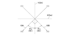
- FIG. 2 is a conceptual diagram showing a detection axis and a detection direction of the acceleration sensor 8.
- FIG. 2 shows a case where the acceleration sensor 8 is viewed from the front of the vehicle 1 in an upright state where the vehicle body is not inclined.
- the vehicle height direction Dh is the same as the vertical direction Y
- the vehicle width direction Dw is the same as the horizontal direction X.
- the acceleration sensor 8 has two detection axes 10A and 10B.
- the detection axes 10A and 10B intersect at an intersection angle ⁇ c that is an acute angle with the vertical direction Y when the vehicle body is in an upright state, that is, at an intersection angle ⁇ c that is greater than 0 ° and less than 90 °.
- the crossing angle ⁇ c is 45 °.
- the acceleration sensor 8 detects the vehicle body acceleration Acc in the detection direction toward the left and right lower sides in the vehicle width direction Dh along the detection shafts 10A and 10B. That is, the direction indicated by the arrow in FIG. 2 of each of the detection axes 10A and 10B is the detection direction, and the acceleration Acc is the direction in which the left and right lower direction increases (+) and the left and right upper direction decreases ( ⁇ ).
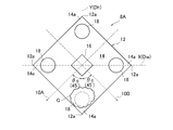
- FIG. 3 is a diagram showing a gas type acceleration sensor 8A that embodies an example of the acceleration sensor 8.
- FIG. 3 shows a case where the gas acceleration sensor 8A of the present embodiment is viewed from the front of the vehicle 1 in an upright state in which the vehicle body is not inclined, as in the case of FIG.
- the vehicle height direction Dh is the same as the vertical direction Y
- the vehicle width direction Dw is the same as the horizontal direction X. Since the gas type acceleration sensor 8A is known, the description thereof is limited to the range necessary for the description of the present embodiment, and the detailed description of the principle and the like is omitted.
- the gas type acceleration sensor 8 ⁇ / b> A includes a rectangular casing 12 having four corners 12 a when viewed from the front of the vehicle 1.
- the casing 12 is formed with a rectangular space 14 filled with a gas G that can move based on the inclination angle ⁇ i of the vehicle body.
- a heater 16 for heating the gas G is disposed in the center of the rectangular space 14.
- a temperature sensor 18 for detecting the temperature of the gas G heated by the heater 16 is disposed at each corner 14 a of the rectangular space 14.
- the gas type acceleration sensor 8A identifies the position and the moving speed of the gas G in the rectangular space 14 by detecting the thermal movement of the gas G heated by the heater 16 by each temperature sensor 18 and by detecting the temperature distribution.
- Each acceleration Acc of the vehicle body along each detection axis 10A, 10B when tilting is detected.
- the pair of opposite corner portions 12a of the housing 12 are in the vertical direction Y, that is, the vehicle height direction Dh It is positioned.
- the gas-type acceleration sensor 8A of the present embodiment is disposed on the vehicle body with an inclination in which the gas G is distributed in the lowermost corner portion 14a of the rectangular space 14.
- the gas G is stably positioned at the corner 14a without excessively moving in the horizontal direction X, and thus each of the gas acceleration sensors 8A The output (detected value) of the acceleration Acc is stabilized.
- the conventional gas acceleration sensor is generally arranged on the vehicle body at a tilt angle of 45 ° when the gas acceleration sensor 8A is viewed in FIG. 3 when the vehicle body is in an upright state.
- the adjacent corners 12 a of the housing 12 are positioned in the horizontal direction X, that is, the vehicle width direction Dw, and the gas G is distributed between the adjacent corners 14 a below the rectangular space 14.
- the detection axes 10A and 10B are positioned along the horizontal direction X and the vertical direction Y, respectively. Therefore, in this conventional case, if the vehicle rolls even a little when the vehicle body is in an upright state, the gas G easily moves in the horizontal direction X, and the output of each acceleration Acc of the gas type acceleration sensor 8A is the vehicle body roll. It becomes an unstable value to which noise due to is added.
- FIG. 4 is a diagram showing a capacitive acceleration sensor 8B that embodies another example of the acceleration sensor 8.
- FIG. 4 shows a case where the capacitive acceleration sensor 8B of the present embodiment is viewed from the front of the vehicle 1 in an upright state in which the vehicle body is not inclined, as in the case of FIGS.
- the vehicle height direction Dh is the same as the vertical direction Y
- the vehicle width direction Dw is the same as the horizontal direction X.
- the capacitive acceleration sensor 8B is publicly known, the description thereof is limited to the range necessary for the description of the present embodiment, and the detailed description of the principle and the like is omitted.
- the capacitive acceleration sensor 8B includes a substrate 20, a fixed electrode 22 fixed to the substrate 20, and a movable electrode 24 that can move based on the inclination angle ⁇ i of the vehicle body.
- the movable electrode 24 is positioned at the center of the substrate 20, and a large number of movable electrode plates 24 a protrude radially from the outer periphery of the movable electrode 24.
- Each movable electrode plate 24a extends in parallel to each detection shaft 10A, 10B.
- the movable electrode 24 is fixed to the substrate 20 by four spring portions 24c.
- the respective spring portions 24c are disposed on the upper and lower sides of the movable electrode 24 in the vertical direction Y and on the left and right sides in the horizontal direction X, thereby allowing a predetermined range of movement of the movable electrode 24 in the vertical and horizontal directions.
- the fixed electrode 22 has a large number of fixed electrode plates 22 a fixed to the substrate 20.
- the fixed electrode plate 22a is disposed opposite to the movable electrode plate 24a and extends in parallel to the detection shafts 10A and 10B.
- the capacitive acceleration sensor 8B detects a change in the distance between the fixed electrode plate 22a and the movable electrode plate 24a, so that each acceleration Acc of the vehicle body along the detection axes 10A and 10B when the vehicle body tilts is detected. Is detected.
- the capacitance type acceleration sensor 8B allows the fixed electrode plate 22a and the movable electrode plate 24a to be inclined to the vehicle body along the detection axes 10A and 10B when the vehicle body is in an upright state where the vehicle body is not inclined. Has been placed.
- both the gravity of the movable electrode 24 and the elastic force of the spring portion 24c against the gravity of the movable electrode 24 act along the vertical direction Y. It will be. Therefore, even if the vehicle body rolls slightly when it is in an upright state, the movable pole plate 24a is stably positioned without excessively moving in the horizontal direction X, and thus each acceleration Acc of the capacitive acceleration sensor 8B. Output is stable.
- the conventional capacitive acceleration sensor is generally arranged on the vehicle body at a tilt angle of 45 ° when the capacitive acceleration sensor 8B is rotated as viewed in FIG. 4 when the vehicle body is in an upright state.
- the gravity of the movable electrode 24 acts downward in the vertical direction Y
- the elastic force of the spring portion 24c acts in a direction intersecting the vertical direction Y and the horizontal direction X at 45 °.
- the detection axes 10A and 10B are positioned along the horizontal direction X and the vertical direction Y, respectively. Therefore, in this conventional case, if the vehicle body rolls even a little when the vehicle body is in an upright state, the movable electrode 24 and thus the movable electrode plate 24a easily move in the horizontal direction X, and each acceleration of the capacitive acceleration sensor 8B. The output of Acc becomes an unstable value in consideration of noise caused by rolling of the vehicle body.
- each acceleration Acc may be an unstable value that takes into account the noise caused by the vertical movement of the vehicle body due to the impact of the vehicle 1 traveling on rough roads or steps.
- the noise can be reduced by limit processing (steps S1 and S3 in FIG. 5) and weighted average processing described later.
- step S1 when this control is started, first, in step S1, whether each acceleration Acc of each detection axis 10A, 10B detected by the acceleration sensor 8 is within a predetermined acceleration range greater than 0 mG and less than 1500 mG. Determine whether or not.
- the determination in step S1 is performed in order to exclude a sudden increase / decrease in acceleration Acc caused by vibration when the vehicle 1 passes through a road surface step or the like from the determination target of the vehicle 1 falling.
- the predetermined acceleration range described above is determined based on the fact that the respective crossing angles ⁇ c of the detection axes 10A and 10B are 45 °.
- step S2 the inclination angle ⁇ i of the vehicle body is calculated by a method described later, and the process proceeds to step S4.
- step S3 it is determined whether or not the time t1 during which each acceleration Acc is outside the predetermined acceleration range continues for a predetermined time of 0.5 seconds.
- step S2 the vehicle body inclination angle ⁇ i is calculated, and then the process proceeds to step S4.
- step S4 the vehicle body inclination angle ⁇ i is calculated, and then the process proceeds to step S4.
- the determination result is No, it is determined that the vehicle 1 has been temporarily inclined or has temporarily passed through a road step, and the process returns to step S1 again, and each acceleration Acc is within a predetermined acceleration range. It is determined whether or not there is.
- step S4 it is determined whether or not the vehicle body inclination angle ⁇ i calculated in step S2 is equal to or greater than a predetermined upper limit threshold of 65 °.
- the process proceeds to step S5.
- the determination result is No, it is determined from the inclination angle ⁇ i that the vehicle 1 has not fallen, and the process returns to step S1 again to determine whether each acceleration Acc is within the predetermined acceleration range. .
- step S5 it is determined whether or not the determination result in step S4 is Yes for a preset time (for example, 3 seconds) or more.
- a preset time for example, 3 seconds
- the determination result is Yes, it is determined that the vehicle body 1 has fallen, and this control is terminated.
- the ECU 6 performs processing such as stopping the engine 2 to prevent the driver or contact object from being involved in the wheels when the vehicle 1 falls, Ensure safety.
- the determination result is No, it is determined that the vehicle 1 has not fallen, and the process returns to step S1 again to determine whether or not each acceleration Acc is within a predetermined acceleration range.
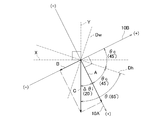
- FIG. 6 is an explanatory diagram of a method for calculating the vehicle body inclination angle ⁇ i in step S2.
- FIG. 6 shows a case where the acceleration sensor 8 is viewed from the front of the vehicle 1 when the vehicle 1 falls.
- the vehicle height direction Dh intersects the vertical direction Y
- the vehicle width direction Dw intersects the horizontal direction X.
- the acceleration sensor 8 detects the acceleration Acc that becomes the vector A in the + direction on the detection axis 10A, and detects the acceleration Acc that becomes the vector B in the ⁇ direction on the detection axis 10B.
- the vectors A and B is expressed as a vector C that goes downward in the vertical direction Y.
- the ECU 6 calculates the intersection angle between the vector C, in other words, the vertical direction Y, and the detection axis 10A as the calculation angle ⁇ i by the arctangent function of each acceleration Acc forming the vectors A and B.
- the calculated angle ⁇ i is, for example, 20 ° in the case of FIG.
- the ECU 6 calculates the sum of the calculated angle ⁇ i (20 °), the detection shaft 10A, the vehicle height direction Dh, and the intersection angle ⁇ c (45 °) as the inclination angle ⁇ i (65 °).
- the tilt angle ⁇ i calculated at this time is equal to or greater than the upper limit threshold (65 °) in step S4 of the overturn determination control shown in FIG. 5, and therefore, it is determined that the vehicle 1 is overturned.
- the correction process for the crossing angle ⁇ c is performed in the initial setting before the start of the control. Specifically, the ECU 6 measures the crossing angle ⁇ c of the detection axes 10A and 10B at that time based on the vector of the accelerations Acc of the detection axes 10A and 10B when the ECU 6 is horizontally placed. Calculate as The actually measured value of the intersection angle ⁇ c is calculated by a learning process executed by the ECU 6.
- the difference between the actually measured value of the calculated intersection angle ⁇ c and the angle (45 °) predetermined as the expected value of the intersection angle ⁇ c is specified as the deviation of the intersection angle ⁇ c of the detection axes 10A and 10B.
- the accelerations Acc detected by the acceleration sensor 8 are corrected to the accelerations Acc that should be detected when there is no deviation of the intersection angle ⁇ c. That is, each acceleration Acc detected by the acceleration sensor 8 is decomposed by the angle of deviation of the intersection angle ⁇ c, thereby calculating each acceleration Acc that should be detected when there is no deviation of the intersection angle ⁇ c.
- Each corrected acceleration Acc is used for the determination in step S1 of the overturn determination control and the calculation of the vehicle body inclination angle ⁇ i in step S2.
- the acceleration Acc is filtered. Specifically, the plurality of accelerations Acc detected by the acceleration sensor 8 are weighted and averaged, and the accelerations Acc after the weighted average are determined in step S1 of the overturn determination control, and the vehicle body inclination angle ⁇ i is calculated in step S2. Used for. Specifically, each acceleration Acc used in the fall determination control is obtained by multiplying the acceleration Acc (n) detected this time by a predetermined weight WGT and the acceleration Acc (n ⁇ 1) detected last time (1 ⁇ weight WGT). It is calculated by adding the value multiplied by the value of.
- the weight WGT is defined in a range larger than 0 and smaller than 1, and for example, a value of 0.5 is applied.
- the acceleration sensor 8 has two detection axes that intersect with the vertical direction Y at an acute angle ⁇ c when the vehicle body is in an upright state without being inclined. 10A, 10B. Then, the acceleration sensor 8 detects the acceleration Acc of the vehicle body in the detection direction toward the lower left and right in the vehicle width direction Dw along the detection axes 10A and 10B.
- the acceleration sensors 10A and 10B when the vehicle body is in the upright state are not positioned along the vertical direction Y and the horizontal direction X, but are positioned so as to intersect the vertical direction Y and the horizontal direction X, thereby 8 can be installed in the vehicle 1 in a posture in which the output is stable, and even if the vehicle body rolls somewhat when it is upright, the output of the acceleration sensor 8 is stable, and the influence of noise due to the vehicle body roll is reduced. It is hard to receive.
- the distribution of the gas G is stable in the case of the gas acceleration sensor 8A shown in FIG. 3, and in the case of the capacitance acceleration sensor 8B shown in FIG. Therefore, the movable electrode plate 24a is stably positioned, and consequently, each acceleration Acc is suppressed from fluctuating excessively. Therefore, in this embodiment, since the noise itself of the output of the acceleration sensor 8 can be reduced, the determination accuracy in the fall determination control can be improved.
- step S4 when it is determined that both the accelerations Acc of the detection axes 10A and 10B detected by the acceleration sensor 8 in step S1 are within a predetermined acceleration range, the vehicle body inclination angle ⁇ i is calculated in step S2. In step S4, if the inclination angle ⁇ i is equal to or greater than the upper limit threshold value, it is determined that the vehicle body 1 has fallen. In this embodiment, by adopting such a two-step determination procedure, it is possible to accurately exclude situations other than a fall such as when the vehicle 1 temporarily passes through a step on the road surface. The determination accuracy in control can be further improved.
- the vehicle body inclination angle ⁇ i is calculated in step S2, and in subsequent steps S4 and S5, the inclination angle ⁇ i is greater than or equal to the upper limit threshold value.
- each acceleration Acc is in the negative direction due to the vehicle 1 passing through a step on the road surface, but the state continues for a predetermined time, it is determined that the vehicle 1 has fallen according to the inclination angle ⁇ i. It becomes possible. Thereby, for example, it is possible to detect the fall of the vehicle 1 in a wide range of situations without excluding the situation where the vehicle 1 has fallen down after being overturned in a complicated posture.
- the accuracy of the fall determination control can be further improved by using each acceleration Acc after the correction process of the intersection angle ⁇ c for the determination. Further, in the fall determination control, by using each acceleration Acc after performing the filtering process based on the weighted average of each acceleration Acc for the determination, the acceleration temporarily increased by the vibration when the vehicle 1 passes through the road step. It is possible to prevent Acc from being erroneously detected as the vehicle 1 falling.
- the present invention is not limited to this, and various modifications can be made without departing from the spirit of the present invention.
- the intersection angle ⁇ c of the detection axes 10A and 10B with the vertical direction Y is not limited to 45 ° as long as it is an acute angle.
- the acceleration range of the acceleration Acc used in the fall determination control, the calculated angle ⁇ i, the upper limit threshold value of the inclination angle ⁇ i, the predetermined time t1, and the like can be changed variously according to the specifications of the acceleration sensor 8 and the fall detection device 4. Is possible.
- the type of the acceleration sensor 8 is not limited to the gas type acceleration sensor 8A and the capacitance type acceleration sensor 8B mentioned as specific examples.
Landscapes
- Physics & Mathematics (AREA)
- Engineering & Computer Science (AREA)
- General Physics & Mathematics (AREA)
- Radar, Positioning & Navigation (AREA)
- Remote Sensing (AREA)
- Emergency Alarm Devices (AREA)
- Vehicle Body Suspensions (AREA)
- Control Of Driving Devices And Active Controlling Of Vehicle (AREA)
- Combined Controls Of Internal Combustion Engines (AREA)
Abstract
自動二輪車(1)の転倒検出装置(4)は、車体の傾斜角(θi)に基づいて自動二輪車(1)が転倒したか否かを検出する転倒検出装置(4)であって、車体が傾斜していない直立状態のときに鉛直方向(Y)と鋭角となる交差角(θc)で交差する2つの検出軸(10A,10B)を有し、各検出軸(10A,10B)に沿って車幅方向(Dw)の左右下方に向かう検出方向で、車体の傾斜角の算出に用いられる車体の加速度(Acc)をそれぞれ検出する加速度センサを備える。
Description
本発明は、自動二輪車の転倒検出装置に関し、特に加速度センサを用いた自動二輪車の転倒検出装置に関する。
特許文献1には、車体が傾斜していない直立状態のときに地面に垂直な方向である第1の検出方向の加速度を検出する縦置きセンサと、第1の検出方向と直角な方向である第2の検出方向の加速度を検出する横置きセンサとを有する自動二輪車の転倒検出装置が開示されている。
この装置では、(横置きセンサ出力)÷(縦置きセンサ出力)の計算結果に基づいて車両が転倒したか否かを判定する。これにより、縦置きセンサ及び横置きセンサにノイズを生じても、縦置きセンサと横置きセンサとの変動が相互に打ち消し合うことにより、加速度センサで予め設定した検出角度において車両が転倒したか否かを精度良く判定することができる、とされている。
しかしながら、特許文献1では、加速度センサの出力である検出信号をA/D変換した値を車両が転倒したか否かの判定に用い、A/D変換幅に基づく変換誤差を低減することで車両が転倒したか否かの判定精度を高めている。従って、特許文献1では、加速度センサの検出値である出力のノイズ自体を低減することについては格別な配慮がなされておらず、自動二輪車が転倒したか否かの判定精度の向上には依然として課題が残されていた。
本発明はこのような課題に鑑みてなされたものであり、その目的とするところは、加速度センサの出力のノイズ自体を低減することにより、自動二輪車が転倒したか否かの判定精度を向上することができる自動二輪車の転倒検出装置を提供することにある。
上記の目的を達成するため、本発明の自動二輪車の転倒検出装置は、車体の傾斜角に基づいて自動二輪車が転倒したか否かを検出する転倒検出装置であって、車体が傾斜していない直立状態のときに鉛直方向と鋭角となる交差角で交差する2つの検出軸を有し、各検出軸に沿って車幅方向の左右下方に向かう検出方向で、車体の傾斜角の算出に用いられる車体の加速度をそれぞれ検出する加速度センサを備える。
好ましくは、各検出軸の交差角はそれぞれ45°である。
好ましくは、加速度センサは、自動二輪車のエンジンを制御する制御ユニットに設けられ、制御ユニットは、加速度センサが検出した各加速度に基づいて自動二輪車が転倒したか否かを判定する判定手段として機能し、判定手段は、加速度センサが検出した各加速度の両方が所定の加速度範囲内であるとき、各加速度に基づき車体の傾斜角を算出し、算出した傾斜角が所定の上限閾値以上となるとき、自動二輪車が転倒したと判定する。
好ましくは、加速度センサは、自動二輪車のエンジンを制御する制御ユニットに設けられ、制御ユニットは、加速度センサが検出した各加速度に基づいて自動二輪車が転倒したか否かを判定する判定手段として機能し、判定手段は、加速度センサが検出した各加速度の両方が所定の加速度範囲内であるとき、各加速度に基づき車体の傾斜角を算出し、算出した傾斜角が所定の上限閾値以上となるとき、自動二輪車が転倒したと判定する。
好ましくは、判定手段は、加速度センサが検出した各加速度の少なくとも1つが加速度範囲外であり、且つ加速度範囲外の状態の時間が所定時間以上継続したとき、各加速度に基づき車体の傾斜角を算出し、算出した傾斜角が上限閾値以上となるとき、自動二輪車が転倒したと判定する。
好ましくは、判定手段は、自動二輪車が転倒したと判定したとき、エンジンを停止する。
好ましくは、判定手段は、自動二輪車が転倒したと判定したとき、エンジンを停止する。
好ましくは、判定手段は、制御ユニットを水平に載置したときの各検出軸の交差角と、交差角の期待値との差を各検出軸の交差角のずれとして特定し、特定した交差角のずれに基づいて加速度センサが検出した各加速度を補正し、補正後の各加速度を自動二輪車が転倒したか否かの判定に使用する。
好ましくは、判定手段は、加速度センサが検出した複数の各加速度を加重平均し、加重平均後の各加速度を自動二輪車が転倒したか否かの判定に使用する。
好ましくは、判定手段は、加速度センサが検出した複数の各加速度を加重平均し、加重平均後の各加速度を自動二輪車が転倒したか否かの判定に使用する。
好ましくは、加速度センサは、車体の傾斜角に基づいて移動可能なガスが充填された矩形空間を有する筐体と、矩形空間に配置され、ガスを加熱するヒータと、矩形空間に配置され、ヒータで加熱されたガスの温度を検出する温度センサとを備え、温度センサによりヒータで加熱されたガスの熱移動を検知することで各検出軸に沿う車体の各加速度を検出するガス式加速度センサであって、ガス式加速度センサは、車体が傾斜していない直立状態のときに矩形空間の隅部にガスが分布する傾きで車体に配置される。
好ましくは、加速度センサは、基板と、基板に固定される固定極板と、固定極板と対向配置され、車体の傾斜角に基づいて移動可能な可動極板とを備え、固定極板と可動極板との距離の変化を検知することで各検出軸に沿う車体の各加速度を検出する静電容量式加速度センサであって、静電容量式加速度センサは、車体が傾斜していない直立状態のときに固定極板及び可動極板が各検出軸に沿う傾きで車体に配置される。
本発明の自動二輪車の転倒検出装置によれば、加速度センサの出力のノイズ自体を低減することにより、自動二輪車が転倒したか否かの判定精度を向上することができる。
以下、図面に基づき本発明の一実施形態に係る自動二輪車の転倒検出装置について説明する。
図1は自動二輪車の転倒検出装置を示す構成図である。自動二輪車1のエンジン2は、例えば排気量50ccの4サイクル単気筒ガソリンエンジンであり、自動二輪車の走行用動力源である。以下、自動二輪車1は、車両1とも称し、また、車両1が転倒する際の傾斜角に関する記述は車体との表現を適宜用いている。
図1は自動二輪車の転倒検出装置を示す構成図である。自動二輪車1のエンジン2は、例えば排気量50ccの4サイクル単気筒ガソリンエンジンであり、自動二輪車の走行用動力源である。以下、自動二輪車1は、車両1とも称し、また、車両1が転倒する際の傾斜角に関する記述は車体との表現を適宜用いている。
車両1の転倒検出装置4は、エンジン2を制御するECU(制御ユニット)6、及びECU6内に設けられた加速度センサ8等から構成されている。ECU6は、プロセッサを有し、後述の転倒判定制御を実現するプログラムをプロセッサによって実行することで、判定手段として機能する。加速度センサ8は、転倒検出装置4において車体の傾斜角θiに基づいて車両1が転倒したか否かを判定するために用いられる。詳しくは、ECU6は、後述する転倒判定制御を実行することにより、加速度センサ8が検出した各加速度Accに基づいて傾斜角θiを算出し、この算出した傾斜角θiに基づいて車両1が転倒したか否かを判定する。
図2は加速度センサ8の検出軸及び検出方向を示す概念図である。図2は、車体が傾斜していない直立状態において加速度センサ8を車両1の前面から見た場合を示している。車高方向Dhは鉛直方向Yと同一であり、車幅方向Dwは水平方向Xと同一である。加速度センサ8は2つの検出軸10A、10Bを有している。各検出軸10A、10Bは、車体が傾斜していない直立状態のときに鉛直方向Yと鋭角となる交差角θc、換言すると、0°より大きく90°よりも小さい交差角θcで交差する。
図2の場合、交差角θcは45°である。そして、加速度センサ8は、車体が直立状態のとき、各検出軸10A、10Bに沿って車幅方向Dhの左右下方に向かう検出方向で車体の加速度Accをそれぞれ検出する。つまり、各検出軸10A、10Bの図2に矢印で示す向きが検出方向であり、加速度Accは左右下方が増大(+)する方向となり、左右上方が減少(-)する方向となる。
図3は、加速度センサ8の一例を具現化したガス式加速度センサ8Aを示す図である。図3は、図2の場合と同様に、車体が傾斜していない直立状態において本実施形態のガス式加速度センサ8Aを車両1の前面から見た場合を示している。車高方向Dhは鉛直方向Yと同一であり、車幅方向Dwは水平方向Xと同一である。なお、ガス式加速度センサ8Aは公知であるため、その説明は本実施形態の説明に必要な範囲に限定し、原理等の詳細な説明は省略する。
ガス式加速度センサ8Aは、車両1の前面から見て4つの角部12aを有する矩形の筐体12を備えている。筐体12には、車体の傾斜角θiに基づいて移動可能なガスGが充填された矩形空間14が形成されている。矩形空間14には、4つの隅部14aが形成されている。矩形空間14の中央にはガスGを加熱するヒータ16が配置されている。また、矩形空間14の各隅部14aには、ヒータ16で加熱されたガスGの温度を検出する温度センサ18がそれぞれ配置されている。
ガス式加速度センサ8Aは、各温度センサ18によってヒータ16で加熱されたガスGの熱移動、ひいては温度分布を検出することにより、矩形空間14におけるガスGの位置や移動速度を特定し、車体が傾斜するときの各検出軸10A、10Bに沿う車体の各加速度Accを検出する。
ここで、図3に示すように、ガス式加速度センサ8Aでは、車体が傾斜していない直立状態のとき、筐体12の対向する一対の角部12aが鉛直方向Y、すなわち車高方向Dhに位置付けられている。
ここで、図3に示すように、ガス式加速度センサ8Aでは、車体が傾斜していない直立状態のとき、筐体12の対向する一対の角部12aが鉛直方向Y、すなわち車高方向Dhに位置付けられている。
換言すると、本実施形態のガス式加速度センサ8Aは、矩形空間14の最下の隅部14aにガスGが分布する傾きで車体に配置されている。これにより、車体が直立状態のときに車体が多少横揺れしたとしても、ガスGは水平方向Xに過度に移動することなく隅部14aに安定して位置付けられ、ひいてはガス式加速度センサ8Aの各加速度Accの出力(検出値)が安定する。
これに対し従来のガス式加速度センサは、一般に、車体が傾斜していない直立状態のときにガス式加速度センサ8Aを図3で見て45°回転した傾きで車体に配置される。この場合には、筐体12の隣り合う角部12aは水平方向X、すなわち車幅方向Dwに位置付けられ、矩形空間14の下部の隣り合う隅部14a間にガスGが分布する。
また、各検出軸10A、10Bは、それぞれ水平方向X、鉛直方向Yに沿って位置付けられる。従って、この従来の場合には、車体が直立状態のときに少しでも横揺れすると、ガスGは水平方向Xに移動し易くなり、ガス式加速度センサ8Aの各加速度Accの出力は車体の横揺れによるノイズが加味された不安定な値となる。
図4は、加速度センサ8の別の一例を具現化した静電容量式加速度センサ8Bを示す図である。図4は、図2、図3の場合と同様に、車体が傾斜していない直立状態において本実施形態の静電容量式加速度センサ8Bを車両1の前面から見た場合を示している。車高方向Dhは鉛直方向Yと同一であり、車幅方向Dwは水平方向Xと同一である。なお、静電容量式加速度センサ8Bは公知であるため、その説明は本実施形態の説明に必要な範囲に限定し、原理等の詳細な説明は省略する。
静電容量式加速度センサ8Bは、基板20と、基板20に固定される固定電極22と、車体の傾斜角θiに基づいて移動可能な可動電極24とを備えている。可動電極24は、基板20の中央に位置付けられ、可動電極24の外周から放射状に多数の可動極板24aが突き出ている。各可動極板24aは各検出軸10A、10Bに平行に延設されている。
また、可動電極24は、4つのバネ部24cにより基板20に固定されている。各バネ部24cは可動電極24の鉛直方向Yの上下と、水平方向Xの左右とに配置され、これより可動電極24の上下左右における所定範囲の移動が許容される。一方、固定電極22は、基板20に固定された多数の固定極板22aを有する。固定極板22aは可動極板24aとそれぞれ対向配置され、各検出軸10A、10Bに平行に延設されている。
そして、静電容量式加速度センサ8Bは、固定極板22aと可動極板24aとの距離の変化を検知することで、車体が傾斜するときの各検出軸10A、10Bに沿う車体の各加速度Accを検出する。このように、本実施形態の静電容量式加速度センサ8Bは、車体が傾斜していない直立状態のときに固定極板22a及び可動極板24aが各検出軸10A、10Bに沿う傾きで車体に配置されている。
このような固定極板22a及び可動極板24aの配置により、可動電極24の重力と、可動電極24の重力に抗するバネ部24cの弾性力との双方は、鉛直方向Yに沿って作用することとなる。従って、車体が直立状態のときに多少横揺れしたとしても、可動極板24aは水平方向Xに過度に移動することなく安定して位置付けられ、ひいては静電容量式加速度センサ8Bの各加速度Accの出力が安定する。
これに対し従来の静電容量式加速度センサは、一般に、車体が傾斜していない直立状態のときに静電容量式加速度センサ8Bを図4で見て45°回転した傾きで車体に配置される。この場合には、可動電極24の重力は鉛直方向Yの下方に作用するのに対し、バネ部24cの弾性力は鉛直方向Y及び水平方向Xと45°で交差する方向に作用する。
また、各検出軸10A、10Bは、それぞれ水平方向X、鉛直方向Yに沿って位置付けられる。従って、この従来の場合には、車体が直立状態のときに少しでも横揺れすると、可動電極24ひいては可動極板24aが水平方向Xに移動し易くなり、静電容量式加速度センサ8Bの各加速度Accの出力は車体の横揺れによるノイズが加味された不安定な値となる。
なお、各加速度Accの出力は、車両1の悪路での走行や段差等による衝撃で、車体の縦揺れによるノイズが加味された不安定な値となる可能性もある。これに対し本実施形態では、後述のリミット処理(図5のステップS1、S3)や加重平均処理により当該ノイズの低減を可能としている。
以下、図5を参照して、ECU6が実行する転倒判定制御のフローチャートについて説明する。この転倒判定制御では、各検出軸10A、10Bのそれぞれの交差角θcが45°であることを前提とし、このときの加速度センサ8が検出した各加速度Accに基づいて傾斜角θiを算出することにより車両1が転倒したか否かが判定される。
詳しくは、本制御が開始されると、先ずステップS1では、加速度センサ8が検出した各検出軸10A、10Bの各加速度Accの両方が0mGよりも大きく1500mGよりも小さい所定加速度範囲内であるか否かを判定する。ステップS1の判定は、車両1が路面の段差等を通過する際の振動によって受けた急激な加速度Accの増減を車両1の転倒の判定対象から除外するために行われる。また、上述した所定加速度範囲は、各検出軸10A、10Bのそれぞれの交差角θcが45°であることに基づいて決定される。
判定結果がYesであるとき、つまり、各検出軸10A、10Bの各加速度Accの両方が0mG<Acc<1500mGであることが成立するとき、車両1が転倒する際に発生する重力の作用方向、すなわち、図2で示した各検出軸10A、10Bの+方向のベクトルとなる各加速度Accが加速度センサ8で検出され、ステップS2に移行する。
一方、判定結果がNoであるとき、つまり、各検出軸10A、10Bの各加速度Accの少なくとも1つが0mG<Acc<1500mGであることが成立しないとき、車両1が転倒する際に発生する重力の作用方向とは反対方向、すなわち、図2で示した各検出軸10A、10Bの-方向のベクトルとなる各加速度Accが検出されたものと判定し、ステップS3に移行する。この場合は、車両1が傾斜している、又は、路面の段差を一時的に通過した際などが想定される。
ステップS2では、後述する手法により車体の傾斜角θiを算出し、ステップS4に移行する。
ステップS3では、各加速度Accが所定加速度範囲外の状態の時間t1が0.5秒となる所定時間以上継続するか否かを判定する。
ステップS3では、各加速度Accが所定加速度範囲外の状態の時間t1が0.5秒となる所定時間以上継続するか否かを判定する。
判定結果がYesであるとき、ステップS2に移行して車体の傾斜角θiを算出した後、ステップS4に移行する。一方、判定結果がNoであるとき、車両1が一時的に傾斜した、又は、路面の段差を一時的に通過したものと判定し、再びステップS1に戻って各加速度Accが所定加速度範囲内であるか否かを判定する。
ステップS4では、ステップS2で算出した車体の傾斜角θiが所定の上限閾値である65°以上であるか否かを判定する。判定結果がYesであるとき、ステップS5に移行する。一方、判定結果がNoであるとき、傾斜角θiから判断して車両1は転倒していないと判定し、再びステップS1に戻って各加速度Accが所定加速度範囲内であるか否かを判定する。
ステップS5では、予め設定された時間(例えば3秒)以上、ステップS4の判定結果がYesとなっているか否かを判定する。判定結果がYesであるとき、車体1が転倒していると判定し、本制御を終了する。車体1が転倒していると判定した後は、ECU6は、エンジン2を停止する等の処理を行うことにより、車両1の転倒時における車輪への運転者や接触物の巻き込み等を防止し、安全を確保する。一方、判定結果がNoであるとき、車両1は転倒していないと判定し、再びステップS1に戻って各加速度Accが所定加速度範囲内であるか否かを判定する。
図6は、ステップS2における車体の傾斜角θiの算出手法についての説明図である。図6は、車両1が転倒した場合において加速度センサ8を車両1の前面から見た場合を示している。車高方向Dhは鉛直方向Yと交差し、車幅方向Dwは水平方向Xと交差している。図6の場合、加速度センサ8は、検出軸10Aにおいて+方向のベクトルAとなる加速度Accを検出し、検出軸10Bにおいて-方向のベクトルBとなる加速度Accを検出しており、これらの加速度AccのベクトルA、Bの合成は鉛直方向Yの下方に向かうベクトルCとして表されている。
そして、ECU6は、ベクトルA、Bを形成する各加速度Accの逆正接関数によって、ベクトルC、換言すると鉛直方向Yと、検出軸10Aとの交差角を算出角Δθiとして算出する。算出角Δθiは、例えば図6の場合には20°である。さらに、ECU6は、この算出角Δθi(20°)と、検出軸10Aと車高方向Dhと交差角θc(45°)との和を傾斜角θi(65°)として算出する。このときに算出した傾斜角θiは、図5に示した転倒判定制御のステップS4の上限閾値(65°)以上であるため、車両1が転倒していると判定される。
さらに、転倒判定制御では、制御開始前の初期設定において、交差角θcの補正処理を行っている。具体的には、ECU6は、ECU6を水平に載置したときの各検出軸10A、10Bの各加速度Accのベクトルに基づいて、そのときの各検出軸10A、10Bの交差角θcを、実測値として算出する。この交差角θcの実測値は、ECU6により実行される学習処理により算出される。
そして、算出した交差角θcの実測値と、交差角θcの期待値として予め定められた角度(45°)との差を各検出軸10A、10Bの交差角θcのずれとして特定し、この特定した交差角θcのずれに基づいて、加速度センサ8が検出した各加速度Accを、交差角θcのずれが無かった場合に検出されるはずの各加速度Accに補正する。すなわち、加速度センサ8が検出した各加速度Accのベクトルを、交差角θcのずれの角度で分解することで、交差角θcのずれが無かった場合に検出されるはずの各加速度Accを算出する。そして、この補正後の各加速度Accを転倒判定制御のステップS1の判定、及び、ステップS2における車体の傾斜角θiの算出に使用する。
さらに、転倒判定制御では、加速度Accのフィルタ処理を行っている。具体的には、加速度センサ8が検出した複数の各加速度Accを加重平均し、加重平均後の各加速度Accを転倒判定制御のステップS1の判定、及び、ステップS2における車体の傾斜角θiの算出に使用する。詳しくは、転倒判定制御で使用する各加速度Accは、今回検出した加速度Acc(n)に所定の重みWGTを乗じた値と、前回検出した加速度Acc(n-1)に(1-重みWGT)の値を乗じた値とを加算することで算出される。重みWGTは、0より大きく1より小さい範囲で規定され、例えば0.5の値が適用される。
以上のように本実施形態の車両1の転倒検出装置4では、加速度センサ8は、車体が傾斜していない直立状態のときに鉛直方向Yと鋭角となる交差角θcで交差する2つの検出軸10A、10Bを有する。そして、加速度センサ8は、各検出軸10A、10Bに沿って車幅方向Dwの左右下方に向かう検出方向で車体の加速度Accをそれぞれ検出する。このように、車体が直立状態のときの各検出軸10A、10Bを鉛直方向Y及び水平方向Xに沿って位置付けるのではなく、鉛直方向Y及び水平方向Xに交差させて位置付けることにより、加速度センサ8をその出力が安定する姿勢で車両1に設置することができ、車体が直立状態のときに多少横揺れしたとしても、加速度センサ8の出力は安定し、車体の横揺れによるノイズの影響を受け難い。
具体的には、車体が直立状態のとき、図3に示したガス式加速度センサ8Aの場合にはガスGの分布は安定し、また、図4で示した静電容量式加速度センサ8Bの場合には可動極板24aが安定して位置付けられ、ひいては各加速度Accが過度に変動することが抑制される。従って、本実施形態では、加速度センサ8の出力のノイズ自体を低減することができるため、転倒判定制御における判定精度を向上することができる。
また、転倒判定制御では、ステップS1で加速度センサ8が検出した各検出軸10A、10Bの各加速度Accの両方が所定加速度範囲内であると判定した場合、ステップS2において車体の傾斜角θiを算出し、その後のステップS4にて傾斜角θiが上限閾値以上となる場合には車体1が転倒していると判定する。本実施形態では、このような二段階の判定手順を採用したことにより、車両1が路面の段差を一時的に通過した場合等の転倒以外の状況を的確に排除することができるため、転倒判定制御における判定精度をさらに向上することができる。
また、転倒判定制御では、ステップS1で加速度センサ8が検出した各検出軸10A、10Bの各加速度Accの少なくとも1つが所定加速度範囲外であると判定した場合であっても、ステップS3において、各加速度Accの少なくとも1つが所定加速度範囲外の状態が所定時間以上継続した場合に限り、ステップS2において車体の傾斜角θiを算出し、その後のステップS4、S5にて傾斜角θiが上限閾値以上である状態が所定時間の間、継続している場合には車体1が転倒していると判定する。
従って、例えば、車両1が路面の段差を通過することにより各加速度Accが-方向になったものの、その状態が所定時間続く場合には、傾斜角θiに応じて車両1が転倒したものと判定可能となる。これにより、例えば、車両1が複雑な姿勢にて横転した後に転倒した状況等を排除しないで、幅広い状況において車両1の転倒を検出することができる。
また、転倒判定制御では、交差角θcの補正処理を行った後の各加速度Accを判定に用いることにより、転倒判定制御の判定精度をさらに向上することができる。
また、転倒判定制御では、各加速度Accの加重平均によるフィルタ処理を行った後の各加速度Accを判定に用いることにより、車両1が路面の段差を通過する際の振動により一時的に増加した加速度Accを車両1が転倒したものとして誤検出することを防止することができる。
また、転倒判定制御では、各加速度Accの加重平均によるフィルタ処理を行った後の各加速度Accを判定に用いることにより、車両1が路面の段差を通過する際の振動により一時的に増加した加速度Accを車両1が転倒したものとして誤検出することを防止することができる。
以上で本発明の一実施形態についての説明を終えるが、本発明はこれに限定されるものではなく、本発明の趣旨を逸脱しない範囲で種々の変更ができるものである。
例えば、検出軸10A、10Bの鉛直方向Yとの交差角θcは鋭角であれば45°に限定されない。また、転倒判定制御で用いられる加速度Accの加速度範囲、算出角Δθi、傾斜角θiの上限閾値、所定時間t1等の値は、加速度センサ8や転倒検出装置4の仕様に応じて種々の変更が可能である。また、加速度センサ8の種類は、具体例として挙げたガス式加速度センサ8Aや静電容量式加速度センサ8Bに限定されない。
例えば、検出軸10A、10Bの鉛直方向Yとの交差角θcは鋭角であれば45°に限定されない。また、転倒判定制御で用いられる加速度Accの加速度範囲、算出角Δθi、傾斜角θiの上限閾値、所定時間t1等の値は、加速度センサ8や転倒検出装置4の仕様に応じて種々の変更が可能である。また、加速度センサ8の種類は、具体例として挙げたガス式加速度センサ8Aや静電容量式加速度センサ8Bに限定されない。
1 自動二輪車(車両、車体)
2 エンジン
4 転倒検出装置
6 ECU(制御ユニット、判定手段)
8 加速度センサ
8A ガス式加速度センサ(加速度センサ)
8B 静電容量式加速度センサ(加速度センサ)
10A、10B 検出軸
12 筐体
14 矩形空間
14a 隅部
16 ヒータ
18 温度センサ
20 基板
22a 固定極板
24a 可動極板
2 エンジン
4 転倒検出装置
6 ECU(制御ユニット、判定手段)
8 加速度センサ
8A ガス式加速度センサ(加速度センサ)
8B 静電容量式加速度センサ(加速度センサ)
10A、10B 検出軸
12 筐体
14 矩形空間
14a 隅部
16 ヒータ
18 温度センサ
20 基板
22a 固定極板
24a 可動極板
Claims (9)
- 車体の傾斜角に基づいて自動二輪車が転倒したか否かを検出する転倒検出装置であって、
前記車体が傾斜していない直立状態のときに鉛直方向と鋭角となる交差角で交差する2つの検出軸を有し、前記各検出軸に沿って車幅方向の左右下方に向かう検出方向で、前記車体の傾斜角の算出に用いられる前記車体の加速度をそれぞれ検出する加速度センサを備えた自動二輪車の転倒検出装置。 - 前記各検出軸の前記交差角はそれぞれ45°である、請求項1に記載の自動二輪車の転倒検出装置。
- 前記加速度センサは、前記自動二輪車のエンジンを制御する制御ユニットに設けられ、
前記制御ユニットは、前記加速度センサが検出した前記各加速度に基づいて前記自動二輪車が転倒したか否かを判定する判定手段として機能し、
前記判定手段は、前記加速度センサが検出した前記各加速度の両方が所定の加速度範囲内であるとき、前記各加速度に基づき前記車体の傾斜角を算出し、算出した前記傾斜角が所定の上限閾値以上となるとき、前記自動二輪車が転倒したと判定する、請求項1又は2に記載の自動二輪車の転倒検出装置。 - 前記判定手段は、前記加速度センサが検出した前記各加速度の少なくとも1つが前記加速度範囲外であり、且つ前記加速度範囲外の状態の時間が所定時間以上継続したとき、前記各加速度に基づき前記車体の傾斜角を算出し、算出した前記傾斜角が前記上限閾値以上となるとき、前記自動二輪車が転倒したと判定する、請求項3に記載の自動二輪車の転倒検出装置。
- 前記判定手段は、前記自動二輪車が転倒したと判定したとき、前記エンジンを停止する、請求項4に記載の自動二輪車の転倒検出装置。
- 前記判定手段は、前記制御ユニットを水平に載置したときの前記各検出軸の前記交差角と、前記交差角の期待値との差を前記各検出軸の前記交差角のずれとして特定し、特定した前記交差角のずれに基づいて前記加速度センサが検出した前記各加速度を補正し、補正後の前記各加速度を前記自動二輪車が転倒したか否かの判定に使用する、請求項1から5の何れか一項に記載の自動二輪車の転倒検出装置。
- 前記判定手段は、前記加速度センサが検出した複数の前記各加速度を加重平均し、加重平均後の前記各加速度を前記自動二輪車が転倒したか否かの判定に使用する、請求項1から6の何れか一項に記載の自動二輪車の転倒検出装置。
- 前記加速度センサは、
前記車体の傾斜角に基づいて移動可能なガスが充填された矩形空間を有する筐体と、
前記矩形空間に配置され、前記ガスを加熱するヒータと、
前記矩形空間に配置され、前記ヒータで加熱されたガスの温度を検出する温度センサと
を備え、前記温度センサにより前記ヒータで加熱された前記ガスの熱移動を検知することで前記各検出軸に沿う前記車体の各加速度を検出するガス式加速度センサであって、
前記ガス式加速度センサは、前記車体が傾斜していない直立状態のときに前記矩形空間の隅部に前記ガスが分布する傾きで前記車体に配置される、請求項1から7の何れか一項に記載の自動二輪車の転倒検出装置。 - 前記加速度センサは、
基板と、
前記基板に固定される固定極板と、
前記固定極板と対向配置され、前記車体の傾斜角に基づいて移動可能な可動極板と
を備え、前記固定極板と前記可動極板との距離の変化を検知することで前記各検出軸に沿う前記車体の各加速度を検出する静電容量式加速度センサであって、
前記静電容量式加速度センサは、前記車体が傾斜していない直立状態のときに前記固定極板及び前記可動極板が前記各検出軸に沿う傾きで前記車体に配置される、請求項1から7の何れか一項に記載の自動二輪車の転倒検出装置。
Priority Applications (1)
| Application Number | Priority Date | Filing Date | Title |
|---|---|---|---|
| CN201880021955.1A CN110461696B (zh) | 2017-03-31 | 2018-01-25 | 摩托车倾倒检测装置 |
Applications Claiming Priority (2)
| Application Number | Priority Date | Filing Date | Title |
|---|---|---|---|
| JP2017-070405 | 2017-03-31 | ||
| JP2017070405A JP6835652B2 (ja) | 2017-03-31 | 2017-03-31 | 自動二輪車の転倒検出装置 |
Publications (1)
| Publication Number | Publication Date |
|---|---|
| WO2018179764A1 true WO2018179764A1 (ja) | 2018-10-04 |
Family
ID=63674913
Family Applications (1)
| Application Number | Title | Priority Date | Filing Date |
|---|---|---|---|
| PCT/JP2018/002343 Ceased WO2018179764A1 (ja) | 2017-03-31 | 2018-01-25 | 自動二輪車の転倒検出装置 |
Country Status (3)
| Country | Link |
|---|---|
| JP (1) | JP6835652B2 (ja) |
| CN (1) | CN110461696B (ja) |
| WO (1) | WO2018179764A1 (ja) |
Families Citing this family (2)
| Publication number | Priority date | Publication date | Assignee | Title |
|---|---|---|---|---|
| JP7226052B2 (ja) * | 2019-04-16 | 2023-02-21 | スズキ株式会社 | 事故判定システム、事故判定方法、プログラム |
| DE102023208206A1 (de) * | 2023-08-28 | 2025-03-06 | Robert Bosch Gesellschaft mit beschränkter Haftung | Sensoreinheit für ein Fahrzeug |
Citations (8)
| Publication number | Priority date | Publication date | Assignee | Title |
|---|---|---|---|---|
| JPH08226816A (ja) * | 1994-10-12 | 1996-09-03 | Temic Telefunken Microelectron Gmbh | 傾斜検出用センサ装置 |
| JPH0943269A (ja) * | 1995-07-28 | 1997-02-14 | Omron Corp | 加速度トランスデューサ |
| JPH10278711A (ja) * | 1997-04-11 | 1998-10-20 | Kubota Corp | 作業車 |
| JP2000028630A (ja) * | 1998-07-08 | 2000-01-28 | Honda Motor Co Ltd | ガス式センサ |
| JP2000221208A (ja) * | 1999-02-02 | 2000-08-11 | Nitta Ind Corp | 静電容量式加速度センサ |
| JP2008144685A (ja) * | 2006-12-11 | 2008-06-26 | Yamaha Motor Co Ltd | エンジン制御装置、及び鞍乗型車両 |
| JP2008192573A (ja) * | 2007-02-08 | 2008-08-21 | Railway Technical Res Inst | 土木構造物の連続測定型転倒検出装置 |
| JP2009264771A (ja) * | 2008-04-22 | 2009-11-12 | Asahi Denso Co Ltd | 車両の傾斜センサ |
Family Cites Families (5)
| Publication number | Priority date | Publication date | Assignee | Title |
|---|---|---|---|---|
| JP4290950B2 (ja) * | 2001-10-19 | 2009-07-08 | ヤマハ発動機株式会社 | 自動二輪車の転倒検出装置 |
| TW561262B (en) * | 2001-10-19 | 2003-11-11 | Yamaha Motor Co Ltd | Tipping detecting device for a motorcycle |
| DE102008043794A1 (de) * | 2008-11-17 | 2010-05-20 | Robert Bosch Gmbh | Verfahren und Vorrichtung zum Bestimmen des Schräglagewinkels eines Zweiradfahrzeugs |
| CN101644718B (zh) * | 2009-07-02 | 2011-08-17 | 中国科学院声学研究所 | 一种带声学腔的电容式加速度传感器 |
| JP6212387B2 (ja) * | 2013-12-27 | 2017-10-11 | 株式会社ケーヒン | 鞍乗り型車両の傾斜角検出装置 |
-
2017
- 2017-03-31 JP JP2017070405A patent/JP6835652B2/ja active Active
-
2018
- 2018-01-25 CN CN201880021955.1A patent/CN110461696B/zh active Active
- 2018-01-25 WO PCT/JP2018/002343 patent/WO2018179764A1/ja not_active Ceased
Patent Citations (8)
| Publication number | Priority date | Publication date | Assignee | Title |
|---|---|---|---|---|
| JPH08226816A (ja) * | 1994-10-12 | 1996-09-03 | Temic Telefunken Microelectron Gmbh | 傾斜検出用センサ装置 |
| JPH0943269A (ja) * | 1995-07-28 | 1997-02-14 | Omron Corp | 加速度トランスデューサ |
| JPH10278711A (ja) * | 1997-04-11 | 1998-10-20 | Kubota Corp | 作業車 |
| JP2000028630A (ja) * | 1998-07-08 | 2000-01-28 | Honda Motor Co Ltd | ガス式センサ |
| JP2000221208A (ja) * | 1999-02-02 | 2000-08-11 | Nitta Ind Corp | 静電容量式加速度センサ |
| JP2008144685A (ja) * | 2006-12-11 | 2008-06-26 | Yamaha Motor Co Ltd | エンジン制御装置、及び鞍乗型車両 |
| JP2008192573A (ja) * | 2007-02-08 | 2008-08-21 | Railway Technical Res Inst | 土木構造物の連続測定型転倒検出装置 |
| JP2009264771A (ja) * | 2008-04-22 | 2009-11-12 | Asahi Denso Co Ltd | 車両の傾斜センサ |
Also Published As
| Publication number | Publication date |
|---|---|
| JP6835652B2 (ja) | 2021-02-24 |
| JP2018171973A (ja) | 2018-11-08 |
| CN110461696B (zh) | 2021-01-15 |
| CN110461696A (zh) | 2019-11-15 |
Similar Documents
| Publication | Publication Date | Title |
|---|---|---|
| CN100554017C (zh) | 车辆阻尼力控制设备 | |
| EP1486382A2 (en) | Vehicle rollover detection method and apparatus | |
| JP5146603B2 (ja) | 車両制御装置及び演算装置 | |
| JP6032119B2 (ja) | 倒立移動体及びその制御方法 | |
| JP2011120383A (ja) | 移動ロボット及びその走行安定化方法 | |
| JP3714207B2 (ja) | 乗員拘束装置 | |
| CN116021939B (zh) | 半主动悬架控制方法及控制装置、存储介质及车辆 | |
| CN108657365A (zh) | 控制电动自行车电机功率的方法、系统及电动自行车 | |
| WO2018179764A1 (ja) | 自動二輪車の転倒検出装置 | |
| JP6420483B2 (ja) | 縦横加速度を使用した傾斜カーブの検出 | |
| WO2021060038A1 (ja) | 車体姿勢検出装置及び鞍乗型車両 | |
| JP6396729B2 (ja) | 立体物検出装置 | |
| JP3992105B2 (ja) | 車両のロールオーバ防止装置 | |
| JP4655913B2 (ja) | 上下加速度センサの検出値を姿勢補正する車輪上下加速度検出装置 | |
| JP5024457B2 (ja) | 車両制御装置 | |
| JP2020085536A (ja) | タッチ検出装置 | |
| JP3875447B2 (ja) | 車両の横転判定方法 | |
| JP2007230531A (ja) | 車両の横転危険度判定装置 | |
| JP2001071844A (ja) | 車両の横転判定方法 | |
| JP2015003686A (ja) | 車両安定装置 | |
| JP4119069B2 (ja) | 車両の横転判定方法 | |
| KR101928154B1 (ko) | 차량의 롤오버 감지 방법 및 장치 | |
| JP2001074442A (ja) | 車両の横転判定方法 | |
| JP4926502B2 (ja) | 車両の安定性評価装置、及び、この安定性評価装置に基づいて運転支援を行う車両の運転支援制御装置 | |
| JP3715146B2 (ja) | 車両の横転判定方法 |
Legal Events
| Date | Code | Title | Description |
|---|---|---|---|
| 121 | Ep: the epo has been informed by wipo that ep was designated in this application |
Ref document number: 18775024 Country of ref document: EP Kind code of ref document: A1 |
|
| NENP | Non-entry into the national phase |
Ref country code: DE |
|
| 122 | Ep: pct application non-entry in european phase |
Ref document number: 18775024 Country of ref document: EP Kind code of ref document: A1 |