WO2018179740A1 - ブレーキ用マスタシリンダ - Google Patents
ブレーキ用マスタシリンダ Download PDFInfo
- Publication number
- WO2018179740A1 WO2018179740A1 PCT/JP2018/002108 JP2018002108W WO2018179740A1 WO 2018179740 A1 WO2018179740 A1 WO 2018179740A1 JP 2018002108 W JP2018002108 W JP 2018002108W WO 2018179740 A1 WO2018179740 A1 WO 2018179740A1
- Authority
- WO
- WIPO (PCT)
- Prior art keywords
- annular groove
- knocker
- hole
- lever
- cylinder body
- Prior art date
- Legal status (The legal status is an assumption and is not a legal conclusion. Google has not performed a legal analysis and makes no representation as to the accuracy of the status listed.)
- Ceased
Links
Images


Classifications
-
- B—PERFORMING OPERATIONS; TRANSPORTING
- B60—VEHICLES IN GENERAL
- B60T—VEHICLE BRAKE CONTROL SYSTEMS OR PARTS THEREOF; BRAKE CONTROL SYSTEMS OR PARTS THEREOF, IN GENERAL; ARRANGEMENT OF BRAKING ELEMENTS ON VEHICLES IN GENERAL; PORTABLE DEVICES FOR PREVENTING UNWANTED MOVEMENT OF VEHICLES; VEHICLE MODIFICATIONS TO FACILITATE COOLING OF BRAKES
- B60T11/00—Transmitting braking action from initiating means to ultimate brake actuator without power assistance or drive or where such assistance or drive is irrelevant
- B60T11/10—Transmitting braking action from initiating means to ultimate brake actuator without power assistance or drive or where such assistance or drive is irrelevant transmitting by fluid means, e.g. hydraulic
- B60T11/16—Master control, e.g. master cylinders
- B60T11/18—Connection thereof to initiating means
-
- B—PERFORMING OPERATIONS; TRANSPORTING
- B60—VEHICLES IN GENERAL
- B60T—VEHICLE BRAKE CONTROL SYSTEMS OR PARTS THEREOF; BRAKE CONTROL SYSTEMS OR PARTS THEREOF, IN GENERAL; ARRANGEMENT OF BRAKING ELEMENTS ON VEHICLES IN GENERAL; PORTABLE DEVICES FOR PREVENTING UNWANTED MOVEMENT OF VEHICLES; VEHICLE MODIFICATIONS TO FACILITATE COOLING OF BRAKES
- B60T7/00—Brake-action initiating means
- B60T7/02—Brake-action initiating means for personal initiation
- B60T7/08—Brake-action initiating means for personal initiation hand actuated
- B60T7/10—Disposition of hand control
-
- B—PERFORMING OPERATIONS; TRANSPORTING
- B62—LAND VEHICLES FOR TRAVELLING OTHERWISE THAN ON RAILS
- B62L—BRAKES SPECIALLY ADAPTED FOR CYCLES
- B62L3/00—Brake-actuating mechanisms; Arrangements thereof
- B62L3/02—Brake-actuating mechanisms; Arrangements thereof for control by a hand lever
-
- G—PHYSICS
- G05—CONTROLLING; REGULATING
- G05G—CONTROL DEVICES OR SYSTEMS INSOFAR AS CHARACTERISED BY MECHANICAL FEATURES ONLY
- G05G1/00—Controlling members, e.g. knobs or handles; Assemblies or arrangements thereof; Indicating position of controlling members
- G05G1/04—Controlling members for hand actuation by pivoting movement, e.g. levers
-
- F—MECHANICAL ENGINEERING; LIGHTING; HEATING; WEAPONS; BLASTING
- F16—ENGINEERING ELEMENTS AND UNITS; GENERAL MEASURES FOR PRODUCING AND MAINTAINING EFFECTIVE FUNCTIONING OF MACHINES OR INSTALLATIONS; THERMAL INSULATION IN GENERAL
- F16C—SHAFTS; FLEXIBLE SHAFTS; ELEMENTS OR CRANKSHAFT MECHANISMS; ROTARY BODIES OTHER THAN GEARING ELEMENTS; BEARINGS
- F16C17/00—Sliding-contact bearings for exclusively rotary movement
- F16C17/04—Sliding-contact bearings for exclusively rotary movement for axial load only
Definitions
- the present invention relates to a brake master cylinder.
- This application claims priority on March 27, 2017 based on Japanese Patent Application No. 2017-061325 filed in Japan, the contents of which are incorporated herein by reference.
- the present invention provides a brake master cylinder capable of suppressing wear of rotating parts.
- a brake master cylinder is disposed so as to straddle the lever and the knocker, a lever disposed in front of the steering grip, a knocker that transmits an operation force to the lever to the piston,
- a cylinder body that houses the piston, a support shaft that is inserted into a through-hole that penetrates the lever, the knocker, and the cylinder body, and supports the lever and the knocker so as to be rotatable with respect to the cylinder body;
- the through hole at a position between at least one of a position between the cylinder body and the lever, a position between the lever and the knocker, and a position between the knocker and the cylinder body.
- An enclosing annular groove is provided.
- the reservoir 1 is a reservoir-integrated brake master cylinder 2 that constitutes a part of the brake master cylinder 2.
- the brake master cylinder 2 is for straddle-type vehicles such as motorcycles, three-wheel buggies, and four-wheel buggies that are mounted in an exposed state.
- the directions are defined by front, rear, left, right, up and down shown in each drawing. This front / rear / left / right / upper / lower / upper / lower / upper / lower / upper / lower / vertical directions substantially coincide with the state of being attached to the vehicle.
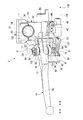
- FIG. 1 is a reservoir-integrated brake master cylinder 2 that constitutes a part of the brake master cylinder 2.
- the brake master cylinder 2 is for straddle-type vehicles such as motorcycles, three-wheel buggies, and four-wheel buggies that are mounted in an exposed state.
- the directions are defined by front, rear, left, right, up and down shown in each drawing. This front / rear / left / right /
- the brake master cylinder 2 is attached to the steering bar 3. Specifically, it is disposed on the front side of the right steering grip 4 that is gripped by the driver's right hand, and is operated by the driver's right hand to introduce brake fluid pressure into a front wheel brake device (not shown).
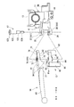
- the brake master cylinder 2 includes a cylinder body 11, a holder 12, a lid portion 13, a lever 14, a knocker 15, a return spring 16, a support shaft 17, and a nut 18 shown in FIG.
- the cylinder body 11 is made of metal and is an integrally formed product by casting.
- the cylinder body 11 is arranged on the front side of the steering bar 3 as shown in FIG.
- a protruding portion 31 is formed on the cylinder body 11 so as to protrude rearward slightly to the right of the center in the left-right direction.
- the cylinder body 11 is attached to the steering bar 3 by sandwiching the steering bar 3 between the protrusion 31 and the holder 12.
- the protrusion 31 and the holder 12 are coupled by two fastening members 32 that are bolts, and sandwich the steering bar 3. Note that only one fastening member 32 is shown because of the plan view in FIG.
- the cylinder body 11 is provided with a plate-like upper support piece 35 and a lower support piece 36 above and below the right side.
- the upper support piece 35 and the lower support piece 36 extend slightly forward and downward.
- the upper support piece portion 35 is formed with a hole portion 37 penetrating the upper support piece portion 35 in the thickness direction
- the lower support piece portion 36 is formed with a hole portion 38 penetrating the upper support piece portion 36 in the thickness direction.
- These hole portions 37 and 38 are formed so that their central axes coincide with each other.
- the hole 37 is orthogonal to the flat lower surface 35a of the upper support piece 35 shown in FIG. 4A
- the hole 38 is orthogonal to the flat upper surface 36a of the lower support piece 36 shown in FIG.
- the lower surface 35a and the upper surface 36a are parallel.
- the hole 37 has a larger diameter than the hole 38.
- the cylinder body 11 is formed with a mirror mounting portion 41 protruding upward at an upper position between the protruding portion 31 and the upper support piece portion 35.
- the mirror mounting part 41 is a part to which a rearview mirror (not shown) is attached.
- the cylinder body 11 is formed with a mounting seat 44 to which a wire stay 43 is fixed by a screw member 42 at a lower portion thereof.
- the cylinder body 11 is provided with a cylinder 50 extending leftward from the base end side of the protruding portion 31.
- the cylinder 50 is disposed in front of the steering bar 3 so as to be along the axial direction of the steering grip 4.
- the cylinder 50 has a bottomed cylindrical shape opening at a position between the upper support piece 35 and the lower support piece 36 shown in FIG.
- a piston 51 indicated by a broken line in FIG. 1 is slidably fitted inside the cylinder 50.
- the cylinder body 11 accommodates the piston 51 in the cylinder 50 so as to be slidable.
- the piston 51 moves along the axial direction of the steering grip 4 and is pushed into the cylinder 50 to generate a brake fluid pressure.
- the cylinder 50 is formed in the lower part of the cylinder body 11, and the reservoir wall part 52 is formed in the upper part from the intermediate part of the cylinder body 11.
- the reservoir wall 52 has a cylindrical shape along the vertical direction, and the opening at the upper end is closed by the lid 13. Brake fluid is stored inside the reservoir wall 52.
- the inside of the reservoir wall portion 52 can communicate with the cylinder 50.
- a window hole 53 is formed in the front portion of the reservoir wall portion 52, and a transparent window member 54 is fitted in the window hole 53. The amount of brake fluid inside the reservoir wall 52 is visible through the window member 54.
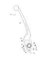
- the lever 14 is made of metal.
- the lever 14 is provided with a base portion 61 at an intermediate portion in the length direction.
- a plate-like supported portion 62 is provided from the base portion 61 to one end portion in the length direction.
- the supported portion 62 extends from the upper portion of the base portion 61 along the length direction of the lever 14.
- the lever 14 is provided with an operation portion 63 operated by the driver from the base portion 61 to the other end portion in the length direction.
- the supported portion 62 includes a plate-like main plate portion 71 that mainly constitutes this, a circular upper boss portion 72 that protrudes upward from the upper surface of the main plate portion 71, and the main plate portion 71.
- a circular lower boss portion 73 projecting downward from the lower surface and a contact portion 74 at the tip of the main plate portion 71 are provided.
- the upper boss portion 72 and the lower boss portion 73 have the same center axis, and a hole 75 penetrating the supported portion 62 in the thickness direction is formed on the center axis.
- the upper end surface 72a of the upper boss portion 72 shown in FIG. 5 is a flat surface, and the lower end surface 73a of the lower boss portion 73 shown in FIG.
- the upper end surface 72 a and the lower end surface 73 a are parallel and orthogonal to the hole 75.
- the hole 75 has substantially the same diameter as the hole 37 of the upper support piece 35 of the cylinder body 11 shown in FIG. 4A.
- a pressing portion 77 is formed between the hole portion 75 of the base portion 61 of the lever 14 and the operation portion 63.
- the pressing portion 77 abuts on and presses the knocker 15 shown in FIG.
- An engagement hole 76 is formed between the upper boss portion 72 and the contact portion 74 of the main plate portion 71.
- the knocker 15 is made of metal.
- the knocker 15 includes a base portion 81, a downward extending portion 82 extending downward from one end portion in the length direction of the base portion 81, and an intermediate portion extending downward from the other end portion in the length direction of the base portion 81.
- the extending portion 83 and the bracket supporting portion 84 extending in parallel with the base portion 81 from the lower portion of the intermediate extending portion 83 are provided.
- the base portion 81 includes a plate-like main plate portion 91 that mainly constitutes the base portion 81, a circular boss portion 92 that protrudes downward from the lower surface of the main plate portion 91, and an action portion 93 that presses the piston 51. Yes.
- a hole portion 94 that penetrates the base portion 81 in the thickness direction is formed.
- the main plate portion 91 has a flat upper surface 91a shown in FIG. 7A
- the boss portion 92 has a flat lower end surface 92a shown in FIG. 7B.
- the upper surface 91a and the lower end surface 92a are parallel and orthogonal to the hole 94.
- the hole 94 has a smaller diameter than the hole 75 of the lever 14 shown in FIG.
- the bracket support portion 84 is also formed with a hole portion 95 penetrating in the thickness direction.
- the return spring 16 shown in FIG. 2 is made of metal, and has a helical coil portion 101, an engagement portion 102 that extends from one end of the coil portion 101, and a hook portion 103 that extends from the other end of the coil portion 101. And have.
- the lever 14 is disposed below the upper support piece 35 of the cylinder body 11, the base portion 81 of the knocker 15 is disposed below the lever 14, and the lower support piece of the cylinder body 11 is disposed below the base portion 81.
- a part 36 is arranged.
- the cylinder body 11 is in a state straddling the lever 14 and the base portion 81 of the knocker 15.
- the hole 37 of the upper support piece 35, the hole 75 of the lever 14, the hole 94 of the knocker 15, and the hole 38 of the lower support piece 36 shown in FIG. Arranged to form one through-hole 111.
- the through hole 111 passes through the lever 14, the knocker 15 and the cylinder body 11.
- the support shaft 17 is inserted into the inside of the coil portion 101 of the return spring 16 shown in FIG. 2 and the through hole 111 made of the holes 37, 75, 94, and 38 shown in FIG. However, the cylinder body 11 can rotate about the support shaft 17. In other words, the support shaft 17 supports the lever 14 and the knocker 15 so as to be rotatable with respect to the cylinder body 11.
- the support shaft 17 is a metal bolt member.
- the support shaft 17 includes a head 121, a large-diameter shaft portion 122 having a smaller diameter than the head 121, a medium-diameter shaft portion 123 having a smaller diameter than the large-diameter shaft portion 122, and a screw having a smaller diameter than the medium-diameter shaft portion 123. And a shaft portion 124.
- the head 121 has a larger diameter than the inner diameter of the coil portion 101 of the return spring 16 shown in FIG. 2, and sandwiches the coil portion 101 with the upper support piece portion 35.
- the large-diameter shaft portion 122 shown in FIG. 3 is fitted into the hole portion 37 of the upper support piece portion 35 of the cylinder body 11 and the hole portion 75 of the lever 14.
- the medium diameter shaft portion 123 is fitted in the hole portion 94 of the knocker 15.
- the screw shaft portion 124 protrudes below the lower support piece portion 36 through the hole 38 of the lower support piece portion 36, and the nut 18 shown in FIG. As a result, the medium diameter shaft portion 123 and the nut 18 sandwich the lower support piece portion 36 to fix the support shaft 17 to the cylinder body 11.
- the return spring 16 sandwiched between the head 121 of the support shaft 17 and the upper support piece 35 of the cylinder body 11 has the engagement portion 102 inserted into the engagement hole 76 of the lever 14 and the hook portion 103 as the upper support piece.
- the lever 14 is biased by being hooked by the portion 35.
- the brake master cylinder 2 has a lever 14 disposed in front of the steering grip 4 when the cylinder body 11 is attached to the steering grip 4 by the holder 12.
- the return spring 16 urges the lever 14 in a direction in which the operation portion 63 is separated from the steering grip 4, that is, forward.
- the lever 14 is restricted from rotating further in the direction in which the operation portion 63 is moved forward by the contact portion 74 contacting the cylinder body 11.
- a pressing portion 77 between the hole portion 75 of the base portion 61 of the lever 14 and the operation portion 63 shown in FIG. 3 is disposed on the front side of the intermediate extension portion 83 of the knocker 15.
- the pressing part 77 of the lever 14 contacts the intermediate extension part 83 of the knocker 15 and rotates the knocker 15 so that the intermediate extension part 83 moves rearward.
- the action part 93 of the knocker 15 pushes the piston 51 shown in FIG.
- the brake fluid is supplied from the brake master cylinder 2 to the front brake device, and the brake is applied. That is, the knocker 15 transmits the operating force to the lever 14 to the piston 51.
- the wire bracket 131 is rotatably attached to the bracket support portion 84 of the knocker 15.
- the wire stay 43 is engaged with the end portion of the outer cable 136 of the wire 135, and the wire bracket 131 is engaged with the end portion of the inner cable 137 of the wire 135.
- the wire 135 is connected to an equalizer disposed in the vicinity of the left steering grip 4 held by the driver's left hand.
- the equalizer is activated by operating the left lever. That is, when the left lever is pulled backward, the brake device for the rear wheel is driven by the equalizer, and the knocker 15 is rotated via the wire 135 to push the piston 51 to operate the brake master cylinder 2. That is, the knocker 15 of the brake master cylinder 2 constitutes a front-rear wheel interlock braking system that operates both the rear wheel brake device and the front wheel brake device only by operating the left lever.
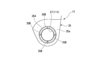
- the upper support piece 35 of the cylinder body 11 is provided with an annular groove 35A having an annular shape surrounding the hole 37 as shown in FIG. 4A, as shown in FIG. It is formed so as to be recessed from the flat lower surface 35a.
- the annular groove 35A is provided below the upper support piece 35, that is, on the lever 14 side shown in FIG.
- the annular groove 35 ⁇ / b> A is arranged coaxially with the hole 37 so that the center axis coincides.
- a communication groove 35B for communicating the annular groove 35A and the hole 37 is formed to be recessed from the lower surface 35a as shown in FIG.
- the communication groove 35B is provided along the radial direction of the annular groove 35A and the hole 37, and a plurality of communication grooves 35B are provided at equal intervals in the circumferential direction of the annular groove 35A and the hole 37.
- the plurality of communication grooves 35 ⁇ / b> B do not extend outward in the radial direction from the annular groove 35 ⁇ / b> A, and are provided in a range between the annular groove 35 ⁇ / b> A and the hole portion 37.
- four communication grooves 35B are provided.
- the annular groove 35A and the plurality of communication grooves 36B are provided at a position between the upper support piece portion 35 of the cylinder body 11 and the upper boss portion 72 of the lever 14 shown in FIG.
- the upper boss portion 72 of the lever 14 is provided with an annular groove 72 ⁇ / b> A that is recessed from the flat upper end surface 72 a in an annular shape surrounding the hole 75.
- the annular groove 72A is provided on the upper side of the lever 14, that is, on the side of the upper support piece 35 shown in FIG.
- the annular groove 72 ⁇ / b> A is disposed coaxially with the central axis of the hole 75.
- the upper boss portion 72 is formed with a communication groove 72B that is recessed from the upper end surface 72a and connects the annular groove 72A and the hole 75.
- the communication groove 72B is along the radial direction of the annular groove 72A and the hole 75, and a plurality of communication grooves 72B are provided at equal intervals in the circumferential direction of the annular groove 72A and the hole 75.
- the plurality of communication grooves 72B do not extend radially outward than the annular groove 72A, and are provided in a range between the annular groove 72A and the hole 75.
- four communication grooves 72B are provided.
- the annular groove 72A and the plurality of communication grooves 72B are provided at a position between the upper support piece portion 35 of the cylinder body 11 and the upper boss portion 72 of the lever 14 shown in FIG.
- the lower boss portion 73 of the lever 14 is provided with an annular groove 73 ⁇ / b> A that is recessed from the flat lower end surface 73 a so as to surround the hole 75.
- the annular groove 73A is provided on the lower side of the lever 14, that is, on the knocker 15 side shown in FIG.
- An annular groove 73 ⁇ / b> A shown in FIG. 6 is arranged coaxially with the hole 75 so that its center axis coincides.
- the annular groove 73A has the same diameter as the annular groove 72A shown in FIG. 5, and the annular groove 72A coincides with the central axis.
- the lower boss portion 73 is formed with a communication groove 73B that is recessed from the lower end surface 73a and connects the annular groove 73A and the hole portion 75 to each other.
- the communication groove 73B extends along the radial direction of the annular groove 73A and the hole 75, and a plurality of communication grooves 73B are provided at equal intervals in the circumferential direction of the annular groove 73A and the hole 75.
- the plurality of communication grooves 73B do not extend radially outward from the annular groove 73A, and are provided in a range between the annular groove 73A and the hole 75.
- four communication grooves 73B are provided.
- the annular groove 73A and the plurality of communication grooves 73B are provided between the lower boss portion 73 of the lever 14 and the main plate portion 91 of the knocker 15 shown in FIG.
- the main plate portion 91 of the knocker 15 is provided with an annular groove 91 ⁇ / b> A that is recessed from the flat upper surface 91 a in an annular shape surrounding the hole portion 94.
- the annular groove 91A is provided on the upper side of the knocker 15, that is, on the lever 14 side shown in FIG.
- the annular groove 91 ⁇ / b> A is arranged coaxially with the central axis line aligned with the hole 94.
- the annular groove 91A has a smaller diameter than the annular grooves 72A and 73A of the lever 14 shown in FIGS.
- the main plate portion 91 is formed with a communication groove 91B that is recessed from the upper surface 91a and allows the annular groove 91A and the hole 94 to communicate with each other.
- the communication groove 91B extends along the radial direction of the annular groove 91A and the hole 94, and a plurality of communication grooves 91B are provided at equal intervals in the circumferential direction of the annular groove 91A and the hole 94.
- the plurality of communication grooves 91 ⁇ / b> B do not extend outward in the radial direction from the annular groove 91 ⁇ / b> A, and are provided in a range between the annular groove 91 ⁇ / b> A and the hole 94.
- the annular groove 91A and the plurality of communication grooves 91B are provided at a position between the lower boss portion 73 of the lever 14 and the main plate portion 91 of the knocker 15 shown in FIG.
- the boss portion 92 of the knocker 15 is provided with an annular groove 92A (a knocker annular groove) that is recessed from the flat lower end surface 92a so as to form an annular shape surrounding the hole portion 94.
- the annular groove 92A is provided on the lower side of the knocker 15, that is, on the lower support piece 36 shown in FIG.
- the annular groove 92 ⁇ / b> A is arranged coaxially with the hole 94 so that the center axis coincides.
- the annular groove 92A has the same diameter as that of the annular groove 91A, and the central axis is made coincident.
- the boss portion 92 is formed with a communication groove 92B that is recessed from the lower end surface 92a and allows the annular groove 92A and the hole portion 94 to communicate with each other.
- the communication grooves 92B are along the radial direction of the annular groove 92A and the hole 94, and a plurality of communication grooves 92B are provided at equal intervals in the circumferential direction of the annular groove 92A and the hole 94.
- the plurality of communication grooves 92 ⁇ / b> B do not extend radially outward from the annular groove 92 ⁇ / b> A, and are provided in a range between the annular groove 92 ⁇ / b> A and the hole 94.
- the annular groove 92A and the plurality of communication grooves 92B are provided at a position between the boss portion 92 of the knocker 15 and the lower support piece portion 36 of the cylinder body 11 shown in FIG.
- the lower support piece 36 of the cylinder body 11 is provided with an annular groove 36A (cylinder body annular groove) that is recessed from the flat upper surface 36a in an annular shape surrounding the hole 38. ing.
- the annular groove 36A is provided on the upper side of the lower support piece 36, that is, on the base 81 side of the knocker 15 shown in FIG.
- the annular groove 36 ⁇ / b> A is disposed coaxially with the central axis line aligned with the hole 38.
- the annular groove 36A of the lower support piece 36 has a larger diameter than the annular grooves 91A and 92A of the knocker 15 shown in FIGS. 7A and 7B.
- the lower support piece 36 is formed with a communication groove 36B that is recessed from the upper surface 36a and allows the annular groove 36A and the hole 38 to communicate with each other.
- the communication grooves 36B are along the radial direction of the annular groove 36A and the hole 38, and a plurality of communication grooves 36B are provided at equal intervals in the circumferential direction of the annular groove 36A and the hole 38.
- the plurality of communication grooves 36 ⁇ / b> B do not extend outward in the radial direction from the annular groove 36 ⁇ / b> A, and are provided in a range between the annular groove 36 ⁇ / b> A and the hole 38.
- four communication grooves 36B are provided.
- the annular groove 36A and the plurality of communication grooves 36B are provided at a position between the boss portion 92 of the knocker 15 and the lower support piece portion 36 of the cylinder body 11 shown in FIG.
- the brake device described in Patent Document 1 constitutes an oil sump by partially forming a notch in the inner peripheral edge of a through hole into which a shaft that supports a lever is fitted. With such a structure, the outflow of grease cannot be suppressed. That is, although a large amount of grease can be held by providing the oil reservoir, the grease supplied from the oil reservoir to the contact surface passes through the contact surface and spreads radially outward from the contact surface. For this reason, grease breakage is likely to occur, and the rotating part is likely to be worn.
- the upper support piece portion 35 is provided with the annular groove 35A, and the upper boss portion of the lever 14 that rotates relative to the lower surface 35a of the upper support piece portion 35 in contact with the upper end surface 72a.
- 72 is provided with an annular groove 72A.
- An annular groove 73A is provided in the lower boss portion 73 of the lever 14, and an annular groove 91A is provided in the main plate portion 91 of the knocker 15 that rotates relative to the lower end surface 73a of the lower boss portion 73 in contact with the upper surface 91a. .
- annular groove 92A is provided in the boss portion 92 of the knocker 15, and an annular groove 36A is provided in the lower support piece portion 36 that rotates in contact with the lower end surface 92a of the boss portion 92 at the upper surface 36a.
- the annular groove 35A, the annular groove 73A, and the annular groove 92A facing downward in the vertical direction can flow the grease downward by gravity and can be supplied to the rotating portion, so that wear can be more effectively suppressed. It becomes.
- annular groove 36A of the lower support piece 36 has a larger diameter than the annular groove 92A of the knocker 15 opposed thereto, the grease flowing downward from the annular groove 92A due to gravity flows out to the outside in the radial direction. Can be suppressed by the annular groove 36A.
- a communication groove 91B that communicates with the hole 94, a communication groove 92B that communicates between the annular groove 92A and the hole 94, and a communication groove 36B that communicates between the annular groove 36A and the hole 38 are provided.
- the grease between the through hole 111 and the support shaft 17 can be passed through the annular grooves 35A, 72A, 73A, 91A, 92A, 36A. Therefore, it is possible to further suppress wear of the rotating part.
- the communication grooves 35B, 72B, 73B, 91B, 92B, and 36B are formed along the radial direction of the through hole 111. However, any or all of these are formed with respect to the radial direction of the through hole 111. May be inclined.
- the communication groove 151 ⁇ / b> B that allows the through hole 111 and the annular groove 151 ⁇ / b> A to communicate with each other may be inclined.
- the grease on the through-hole 111 side can be guided by the communication groove 151B and flow into the annular groove 151A using the relative rotation of the rotating part.
- the plurality of communication grooves 151B may be similarly curved in the circumferential direction to form a spiral shape.
- a concave portion that is recessed from the lower surface 35a to be shallower than the annular groove 35A may be provided on the whole between the annular groove 35A and the hole portion 37.
- a concave portion that is recessed from the upper end surface 72a to be shallower than the annular groove 72A may be provided in the entire area between the annular groove 72A and the hole 75 without providing the communication groove 72B.
- a concave portion that is recessed from the lower end surface 73a to be shallower than the annular groove 73A may be provided on the whole between the annular groove 73A and the hole 75.
- a concave portion that is recessed from the upper surface 91a to be shallower than the annular groove 91A may be provided on the whole between the annular groove 91A and the hole 94.
- a concave portion that is recessed from the lower end surface 92a to be shallower than the annular groove 92A may be provided on the whole between the annular groove 92A and the hole 94.
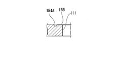
- a concave portion that is recessed from the upper surface 36a to be shallower than the annular groove 36A may be provided on the whole between the annular groove 36A and the hole 38. That is, as in the modification shown in FIG. 10, a concave portion 155 that is recessed shallower than the annular groove 154A is provided between the through hole 111 and the annular groove 154A.
- annular groove 35A and the communication groove 35B are provided in the upper support piece 35, and the annular groove 72A and the communication groove 72B are provided in the upper boss portion 72 of the lever 14 opposite thereto.
- annular groove 73A and a communication groove 73B are provided in the lower boss portion 73 of the lever 14, and an annular groove 91A and a communication groove 91B are provided in the main plate portion 91 of the knocker 15 opposite to the annular groove 73A.
- An annular groove and a communication groove may be provided only on one side. That is, an annular groove that surrounds the through hole 111 and a communication groove that allows the annular groove and the through hole 111 to communicate with each other need only be provided between the lever 14 and the knocker 15.
- annular groove 92A and a communication groove 92B are provided in the boss portion 92 of the knocker 15, and an annular groove 36A and a communication groove 36B are provided in the lower support piece portion 36 of the cylinder body 11 opposite to the annular groove 92A.
- An annular groove that surrounds the through hole 111 and a communication groove that allows the annular groove and the through hole 111 to communicate with each other may be provided in only one of the three places.
- An annular groove that surrounds the through hole 111 and a communication groove that allows the annular groove and the through hole 111 to communicate with each other may be provided only in any two of the three places. That is, the position between the upper support piece 35 of the cylinder body 11 and the lever 14, the position between the lever 14 and the knocker 15, and the position between the knocker 15 and the lower support piece 36 of the cylinder body 11.
- An annular groove surrounding the through hole 111 and a communication groove for communicating the annular groove and the through hole 111 need only be provided in at least one of the three places.
- annular groove 73A and a communication groove 73B are provided in the lower boss portion 73 of the lever 14, an annular groove 91A and a communication groove 91B are provided in the main plate portion 91 of the knocker 15 opposed thereto, and the boss portion 92 of the knocker 15 is provided. It is effective to provide the annular groove 92A and the communication groove 92B.
- the embodiment includes a lever disposed in front of the steering grip, a knocker that transmits an operation force to the lever to the piston, a cylinder body that is disposed so as to straddle the lever and the knocker, and accommodates the piston.
- a support shaft that is inserted into a through-hole penetrating the lever, the knocker, and the cylinder body, and supports the lever and the knocker so as to be rotatable with respect to the cylinder body.
- An annular groove surrounding the through hole is provided at a position between at least one of a position between the lever, a position between the lever and the knocker, and a position between the knocker and the cylinder body. .
- the said annular groove is provided in the position between the said knocker and the said cylinder body.
- the said annular groove is a knocker annular groove provided in the said cylinder body side of the said knocker, and a cylinder body annular groove provided in the said knocker side of the said cylinder body,
- the said cylinder body annular The groove has a larger diameter than the knocker annular groove.
- the communication groove which connects the said annular groove and the said through-hole is provided.
- the communicating groove inclines with respect to the radial direction of a through-hole.
Landscapes
- Engineering & Computer Science (AREA)
- Mechanical Engineering (AREA)
- Transportation (AREA)
- Physics & Mathematics (AREA)
- General Physics & Mathematics (AREA)
- Automation & Control Theory (AREA)
- Transmission Of Braking Force In Braking Systems (AREA)
- Mechanical Control Devices (AREA)
- Braking Elements And Transmission Devices (AREA)
- Sliding-Contact Bearings (AREA)
- Steering-Linkage Mechanisms And Four-Wheel Steering (AREA)
Abstract
このブレーキ用マスタシリンダは、ステアリンググリップの前方に配置されるレバーと、前記レバーへの操作力をピストンに伝達するノッカーと、前記レバー及び前記ノッカーを跨ぐように配置され、前記ピストンを収容するシリンダボディと、前記レバー、前記ノッカー及び前記シリンダボディを貫通する貫通孔に挿通されて、前記レバー及び前記ノッカーを前記シリンダボディに対して回動可能に支持する支持軸と、を備え、前記シリンダボディと前記レバーとの間位置、前記レバーと前記ノッカーとの間位置、及び、前記ノッカーと前記シリンダボディとの間位置の少なくともいずれか一つの間位置に、前記貫通孔を囲む環状溝が設けられている。
Description
本発明は、ブレーキ用マスタシリンダに関する。
本願は、2017年3月27日に、日本に出願された特願2017-061325号に基づき優先権を主張し、その内容をここに援用する。
本願は、2017年3月27日に、日本に出願された特願2017-061325号に基づき優先権を主張し、その内容をここに援用する。
レバーを支持する軸が嵌合される貫通孔の内周縁に切り欠きを形成して油溜まりとするブレーキ装置がある(例えば、特許文献1参照)。
ブレーキ用マスタシリンダにおいては、回転部分の摩耗を抑制することが求められている。
本発明は、回転部分の摩耗を抑制することが可能なブレーキ用マスタシリンダを提供する。
本発明の一態様に係るブレーキ用マスタシリンダは、ステアリンググリップの前方に配置されるレバーと、前記レバーへの操作力をピストンに伝達するノッカーと、前記レバー及び前記ノッカーを跨ぐように配置され、前記ピストンを収容するシリンダボディと、前記レバー、前記ノッカー及び前記シリンダボディを貫通する貫通孔に挿通されて、前記レバー及び前記ノッカーを前記シリンダボディに対して回動可能に支持する支持軸と、を備え、前記シリンダボディと前記レバーとの間位置、前記レバーと前記ノッカーとの間位置、及び、前記ノッカーと前記シリンダボディとの間位置の少なくともいずれか一つの間位置に、前記貫通孔を囲む環状溝が設けられている。
上記したマスタシリンダによれば、回転部分の摩耗を抑制することが可能なブレーキ用マスタシリンダを提供することができる。
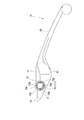
本発明に係る一実施形態を図面に基づいて説明する。本発明の実施形態は、図1及び図2に示すように、リザーバ1がブレーキ用マスタシリンダ2の一部を構成するリザーバ一体型のブレーキ用マスタシリンダ2となっている。このブレーキ用マスタシリンダ2は、外部に露出した状態で取り付けられる自動二輪車、三輪バギー及び四輪バギー等の鞍乗型車両用のものである。ここでは、説明の便宜上、各図に示す前後左右上下で方向を規定して説明する。この前後左右上下は車両に取り付けられた状態とほぼ一致する。図1に示すように、ブレーキ用マスタシリンダ2はステアリングバー3に取り付けられている。具体的には、運転者の右手により把持される右側のステアリンググリップ4の前側に配置されており、運転者の右手により操作されて図示略の前輪のブレーキ装置にブレーキ液圧を導入する。
ブレーキ用マスタシリンダ2は、シリンダボディ11とホルダ12と蓋部13とレバー14とノッカー15と戻しバネ16と支持軸17と図2に示すナット18とを有している。
シリンダボディ11は、金属製であって、鋳造による一体成形品である。シリンダボディ11は、図1に示すようにステアリングバー3の前側に配置されている。シリンダボディ11には、その左右方向中央よりもやや右側に、後方に向けて突出するように突出部31が形成されている。シリンダボディ11は、この突出部31とホルダ12とでステアリングバー3を挟持することでステアリングバー3に取り付けられている。突出部31とホルダ12とはボルトである二本の締結部材32によって結合されてステアリングバー3を挟持する。なお、図1において平面図で表した関係上、締結部材32が一本のみ示されている。
シリンダボディ11は、図3に示すように、その右側部の上下に、いずれも板状の上側支持片部35及び下側支持片部36が設けられている。上側支持片部35及び下側支持片部36は、前方に向けて若干前下がりに延出している。上側支持片部35には、これを厚さ方向に貫通する孔部37が形成されており、下側支持片部36にも、これを厚さ方向に貫通する孔部38が形成されている。これら孔部37,38は、互いの中心軸線を一致させて形成されている。孔部37は上側支持片部35の平坦な図4Aに示す下面35aに直交しており、孔部38は下側支持片部36の平坦な図4Bに示す上面36aに直交している。下面35a及び上面36aは平行である。孔部37は孔部38よりも大径となっている。
図1に示すように、シリンダボディ11には、突出部31と上側支持片部35との間位置の上部に、ミラー装着部41が上方に突出するように形成されている。ミラー装着部41は、図示略のバックミラーが取り付けられる部分である。また、シリンダボディ11には、図2に示すように、その下部に、ネジ部材42によってワイヤステー43が固定される取付座44が形成されている。
図1に示すように、シリンダボディ11には、突出部31の基端側から左方に延出するシリンダ50が設けられている。このシリンダ50は、ステアリングバー3の前方にステアリンググリップ4の軸方向に沿うように配置されている。このシリンダ50は、図2に示す上側支持片部35及び下側支持片部36の間位置に開口する有底筒状をなしている。シリンダ50の内側には、図1において破線で示すピストン51が摺動可能に嵌合されている。言い換えれば、シリンダボディ11は、そのシリンダ50内にピストン51を摺動可能に収容する。ピストン51は、ステアリンググリップ4の軸方向に沿って移動し、シリンダ50内に押し込まれることでブレーキ液圧を発生させる。
図2に示すように、シリンダ50は、シリンダボディ11の下部に形成されており、シリンダボディ11の中間部から上部にはリザーバ壁部52が形成されている。このリザーバ壁部52は、上下方向に沿う筒状をなしており、上端の開口部が蓋部13で閉塞されている。リザーバ壁部52の内側にブレーキ液が貯留される。リザーバ壁部52内はシリンダ50内に連通可能となっている。リザーバ壁部52の前部には窓穴53が形成されており、この窓穴53には透明な窓部材54が嵌合されている。窓部材54を介してリザーバ壁部52の内側のブレーキ液の液量を目視可能となっている。
レバー14は金属製である。レバー14には、長さ方向の中間部にベース部61が設けられている。このベース部61から長さ方向の一端部まで板状の被支持部62が設けられている。被支持部62は、ベース部61の上部からレバー14の長さ方向に沿って延出している。また、レバー14には、ベース部61から長さ方向の他端部まで、運転者により操作される操作部63が設けられている。
被支持部62は、図3に示すように、これを主体的に構成する板状の主板部71と、主板部71の上面から上方に突出する円形の上側ボス部72と、主板部71の下面から下方に突出する円形の下側ボス部73と、主板部71の先端の当接部74とを有している。上側ボス部72及び下側ボス部73は中心軸線を一致させており、この中心軸線上に、被支持部62を厚さ方向に貫通する孔部75が形成されている。
上側ボス部72の図5に示す上端面72aは平坦面となっており、下側ボス部73の図6に示す下端面73aも平坦面となっている。これら上端面72aと下端面73aとは平行であり、孔部75と直交している。孔部75は、図4Aに示すシリンダボディ11の上側支持片部35の孔部37とほぼ同径となっている。図6に示すように、レバー14のベース部61の孔部75と操作部63との間が押圧部77となっている。押圧部77は、図3に示すノッカー15に当接してこれを押圧する。主板部71の上側ボス部72と当接部74との間には係合穴76が形成されている。
ノッカー15は金属製である。ノッカー15は、ベース部81と、ベース部81の長さ方向の一端部から下方に延出する下方延出部82と、ベース部81の長さ方向の他端部から下方に延出する中間延出部83と、中間延出部83の下部からベース部81と平行に延出するブラケット支持部84と、を有している。
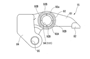
ベース部81は、これを主体的に構成する板状の主板部91と、主板部91の下面から下方に突出する円形のボス部92と、ピストン51を押圧する作用部93とを有している。ボス部92の中心軸線上には、ベース部81を厚さ方向に貫通する孔部94が形成されている。主板部91は図7Aに示す上面91aが平坦面となっており、ボス部92は図7Bに示す下端面92aが平坦面となっている。これら上面91aと下端面92aとは平行であり、孔部94と直交している。孔部94は、図3に示すレバー14の孔部75よりも小径である。ブラケット支持部84にも厚さ方向に貫通する孔部95が形成されている。
図2に示す戻しバネ16は、金属製であり、螺旋状のコイル部101と、コイル部101の一端から延出する係合部102と、コイル部101の他端から延出する引掛部103とを有している。
シリンダボディ11の上側支持片部35の下側にレバー14が配置され、レバー14の下側にノッカー15のベース部81が配置され、ベース部81の下側にシリンダボディ11の下側支持片部36が配置される。この状態では、シリンダボディ11が、レバー14及びノッカー15のベース部81を跨ぐ状態となる。この状態で、図3に示す上側支持片部35の孔部37と、レバー14の孔部75と、ノッカー15の孔部94と、下側支持片部36の孔部38と、が連続的に配置されて一つの貫通孔111となる。言い換えれば、この貫通孔111は、レバー14、ノッカー15及びシリンダボディ11を貫通する。
図2に示す戻しバネ16のコイル部101の内側と、図3に示す孔部37,75,94,38からなる貫通孔111とに支持軸17が挿通されることにより、レバー14及びノッカー15が、シリンダボディ11に対し、この支持軸17を中心として回転可能となる。言い換えれば、支持軸17がレバー14及びノッカー15をシリンダボディ11に対して回転可能となるように支持する。
支持軸17は、金属製のボルト部材である。支持軸17は、頭部121と、頭部121よりも小径の大径軸部122と、大径軸部122よりも小径の中径軸部123と、中径軸部123よりも小径のネジ軸部124とを有している。
頭部121は、図2に示す戻しバネ16のコイル部101の内径よりも大径となっており、コイル部101を上側支持片部35とで挟む。図3に示す大径軸部122は、シリンダボディ11の上側支持片部35の孔部37とレバー14の孔部75とに嵌合する。中径軸部123はノッカー15の孔部94に嵌合する。ネジ軸部124は下側支持片部36の孔部38を通って下側支持片部36よりも下側に突出し、この部分に図2に示すナット18が螺合される。これにより、中径軸部123とナット18とが下側支持片部36を挟持して支持軸17をシリンダボディ11に固定する。
支持軸17の頭部121とシリンダボディ11の上側支持片部35とに挟持された戻しバネ16は、係合部102がレバー14の係合穴76に挿入され、引掛部103が上側支持片部35に引っ掛けられることにより、レバー14を付勢する。
図1に示すように、ブレーキ用マスタシリンダ2は、シリンダボディ11がホルダ12によってステアリンググリップ4に取り付けられる際に、ステアリンググリップ4の前方にレバー14が配置される。この状態で、戻しバネ16は、操作部63がステアリンググリップ4から離れる方向、つまり前方にレバー14を付勢する。レバー14は、図2に示すように当接部74がシリンダボディ11に当接することにより、操作部63を前方に移動させる方向のそれ以上の回転が規制される。
図3に示すレバー14のベース部61の孔部75と操作部63との間の押圧部77がノッカー15の中間延出部83の前側に配置されている。レバー14の操作部63が後方に引かれると、レバー14の押圧部77は、ノッカー15の中間延出部83に当接し、この中間延出部83が後方に移動するようにノッカー15を回転させる。すると、ノッカー15の作用部93が、図1に示すピストン51を押す。これにより、ブレーキ用マスタシリンダ2からフロントのブレーキ装置にブレーキ液が供給されてブレーキがかかる。つまり、ノッカー15は、レバー14への操作力をピストン51に伝達する。
図2に示すように、ノッカー15のブラケット支持部84には、ワイヤブラケット131が回動可能に取り付けられている。上記したワイヤステー43には、ワイヤ135のアウタケーブル136の末端部が係合されており、ワイヤブラケット131には、このワイヤ135のインナケーブル137の末端部が係合されている。このワイヤ135は、図示は略すが、運転者の左手により把持される左側のステアリンググリップ4の近傍に配置されたイコライザに連結されている。左側のレバーが操作されることで、このイコライザを作動する。すなわち、左側のレバーが後方に引かれると、イコライザによって後輪のブレーキ装置を駆動するとともに、ワイヤ135を介してノッカー15を回動させてピストン51を押してブレーキ用マスタシリンダ2を作動させる。つまり、このブレーキ用マスタシリンダ2のノッカー15は、左側のレバーの操作のみで後輪のブレーキ装置と前輪のブレーキ装置とを両方作動させる前後輪連動制動システムを構成する。
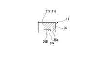
本発明の実施形態において、シリンダボディ11の上側支持片部35には、図4Aに示すように孔部37を囲む円環状をなす環状溝35Aが、図8に示すように上側支持片部35の平坦な下面35aよりも凹んで形成されている。環状溝35Aは上側支持片部35の下側つまり図2に示すレバー14側に設けられている。図4Aに示すように環状溝35Aは、孔部37に対し中心軸線を一致させて同軸状に配置されている。
上側支持片部35には、環状溝35Aと孔部37とを連通させる連通溝35Bが、図8に示すように下面35aよりも凹んで形成されている。図4Aに示すように連通溝35Bは、環状溝35A及び孔部37の径方向に沿っており、環状溝35A及び孔部37の周方向に等間隔で複数設けられている。複数の連通溝35Bは、環状溝35Aよりも径方向外側に延出することはなく、環状溝35Aと孔部37との間の範囲内に設けられている。連通溝35Bは具体的には4箇所設けられている。これら環状溝35A及び複数の連通溝36Bは、互いに接触するシリンダボディ11の上側支持片部35と図2に示すレバー14の上側ボス部72との間位置に設けられている。
図5に示すように、レバー14の上側ボス部72には、平坦な上端面72aよりも凹む環状溝72Aが、孔部75を囲む円環状をなして設けられている。環状溝72Aはレバー14の上側つまり図2に示す上側支持片部35側に設けられている。図5に示すように、環状溝72Aは孔部75に対し中心軸線を一致させて同軸状に配置されている。
上側ボス部72には、上端面72aよりも凹んで環状溝72Aと孔部75とを連通させる連通溝72Bが形成されている。連通溝72Bは環状溝72A及び孔部75の径方向に沿っており、環状溝72A及び孔部75の周方向に等間隔で複数設けられている。複数の連通溝72Bは、環状溝72Aよりも径方向外側に延出することはなく、環状溝72Aと孔部75との間の範囲内に設けられている。連通溝72Bは具体的には4箇所設けられている。これら環状溝72A及び複数の連通溝72Bは、互いに接触する図2に示すシリンダボディ11の上側支持片部35とレバー14の上側ボス部72との間位置に設けられている。
また、図6に示すように、レバー14の下側ボス部73には、平坦な下端面73aよりも凹む環状溝73Aが、孔部75を囲む円環状をなして設けられている。環状溝73Aはレバー14の下側つまり図2に示すノッカー15側に設けられている。図6に示す環状溝73Aは孔部75に対し中心軸線を一致させて同軸状に配置されている。環状溝73Aは、図5に示す環状溝72Aと同径であり、環状溝72Aと中心軸線を一致させている。
図6に示すように、下側ボス部73には、下端面73aよりも凹んで環状溝73Aと孔部75とを連通させる連通溝73Bが形成されている。連通溝73Bは環状溝73A及び孔部75の径方向に沿っており、環状溝73A及び孔部75の周方向に等間隔で複数設けられている。複数の連通溝73Bは、環状溝73Aよりも径方向外側に延出することはなく、環状溝73Aと孔部75との間の範囲内に設けられている。連通溝73Bは具体的には4箇所設けられている。これら環状溝73A及び複数の連通溝73Bは、互いに接触する図2に示すレバー14の下側ボス部73とノッカー15の主板部91との間位置に設けられている。
図7Aに示すように、ノッカー15の主板部91には、平坦な上面91aよりも凹む環状溝91Aが、孔部94を囲む円環状をなして設けられている。環状溝91Aはノッカー15の上側つまり図2に示すレバー14側に設けられている。図7Aに示すように、環状溝91Aは孔部94に対し中心軸線を一致させて同軸状に配置されている。環状溝91Aは、図5,図6に示すレバー14の環状溝72A,73Aよりも小径となっている。
主板部91には、上面91aよりも凹んで環状溝91Aと孔部94とを連通させる連通溝91Bが形成されている。連通溝91Bは環状溝91A及び孔部94の径方向に沿っており、環状溝91A及び孔部94の周方向に等間隔で複数設けられている。複数の連通溝91Bは、環状溝91Aよりも径方向外側に延出することはなく、環状溝91Aと孔部94との間の範囲内に設けられている。連通溝91Bは具体的には4箇所設けられている。これら環状溝91A及び複数の連通溝91Bは、互いに接触する図2に示すレバー14の下側ボス部73とノッカー15の主板部91との間位置に設けられている。
図7Bに示すように、ノッカー15のボス部92には、平坦な下端面92aよりも凹む環状溝92A(ノッカー環状溝)が、孔部94を囲む円環状をなして設けられている。環状溝92Aはノッカー15の下側つまり図2に示す下側支持片部36側に設けられている。図7Bに示すように、環状溝92Aは孔部94に対し中心軸線を一致させて同軸状に配置されている。環状溝92Aは環状溝91Aと同径となっており、中心軸線を一致させている。
ボス部92には、下端面92aよりも凹んで環状溝92Aと孔部94とを連通させる連通溝92Bが形成されている。連通溝92Bは、環状溝92A及び孔部94の径方向に沿っており、環状溝92A及び孔部94の周方向に等間隔で複数設けられている。複数の連通溝92Bは、環状溝92Aよりも径方向外側に延出することはなく、環状溝92Aと孔部94との間の範囲内に設けられている。連通溝92Bは具体的には4箇所設けられている。これら環状溝92A及び複数の連通溝92Bは、互いに接触する図2に示すノッカー15のボス部92とシリンダボディ11の下側支持片部36との間位置に設けられている。
図4Bに示すように、シリンダボディ11の下側支持片部36には、平坦な上面36aよりも凹む環状溝36A(シリンダボディ環状溝)が、孔部38を囲む円環状をなして設けられている。環状溝36Aは下側支持片部36の上側つまり図2に示すノッカー15のベース部81側に設けられている。図4Bに示すように、環状溝36Aは、孔部38に対し中心軸線を一致させて同軸状に配置されている。下側支持片部36の環状溝36Aは、図7A,図7Bに示すノッカー15の環状溝91A,92Aよりも大径となっている。
図4Bに示すように、下側支持片部36には、上面36aよりも凹んで環状溝36Aと孔部38とを連通させる連通溝36Bが形成されている。連通溝36Bは環状溝36A及び孔部38の径方向に沿っており、環状溝36A及び孔部38の周方向に等間隔で複数設けられている。複数の連通溝36Bは、環状溝36Aよりも径方向外側に延出することはなく、環状溝36Aと孔部38との間の範囲内に設けられている。連通溝36Bは具体的には4箇所設けられている。これら環状溝36A及び複数の連通溝36Bは、互いに接触する図2に示すノッカー15のボス部92とシリンダボディ11の下側支持片部36との間位置に設けられている。
上記特許文献1に記載のブレーキ装置は、レバーを支持する軸が嵌合される貫通孔の内周縁に部分的に切り欠きを形成して油溜まりを構成する。このような構造では、グリスの流出を抑制することができない。つまり、油溜まりを設けることでグリスを多く保持することができるものの、油溜まりから接触面に供給されたグリスは、接触面を通過して接触面よりも径方向外側に広がってしまう。このため、グリス切れが発生し易く、回転部分が摩耗し易い。
これに対し、本発明の実施形態によれば、上側支持片部35に環状溝35Aを設け、上側支持片部35の下面35aに上端面72aにおいて接触して相対回転するレバー14の上側ボス部72に環状溝72Aを設けている。また、レバー14の下側ボス部73に環状溝73Aを設け、下側ボス部73の下端面73aに上面91aにおいて接触して相対回転するノッカー15の主板部91に環状溝91Aを設けている。さらに、ノッカー15のボス部92に環状溝92Aを設け、ボス部92の下端面92aに上面36aにおいて接触して相対回転する下側支持片部36に環状溝36Aを設けている。
これにより、環状溝35A,72A,73A,91A,92A,36Aにグリスを溜めることができると共に、環状溝35A,72A,73A,91A,92A,36Aによって、グリスを堰き止めることで、これらよりも径方向外側にグリスが流出することを抑制できる。このため、グリスが相対回転する回転部分の接触範囲よりも外側に漏れ出てしまうことを抑制できる。したがって、接触して相対回転する回転部分の摩耗を抑制することが可能となる。
特に、鉛直方向下に向く環状溝35A、環状溝73A及び環状溝92Aは、重力によってグリスを下方に流動させて回転部分に供給することができるため、より効果的に摩耗を抑制することが可能となる。
また、ノッカー15には、主板部91よりも下側のブラケット支持部84にワイヤ135から荷重が加わる。これにより、ノッカー15は、主板部91が下方向の力を受けて、シリンダボディ11の下側支持片部36に押し付けられることになる。このため、ノッカー15のボス部92に環状溝92Aを設け、ボス部92の下端面92aに上面36aにおいて接触して相対回転する下側支持片部36に環状溝36Aを設けていることにより、ボス部92と下側支持片部36とに生じ易い摩耗を効果的に抑制することができる。
また、下側支持片部36の環状溝36Aが、これに対向するノッカー15の環状溝92Aよりも大径であるため、環状溝92Aから重力により下方に流動するグリスの径方向外側への流出を環状溝36Aで抑制することができる。
また、環状溝35Aと孔部37とを連通させる連通溝35B、環状溝72Aと孔部75とを連通させる連通溝72B、環状溝73Aと孔部75とを連通させる連通溝73B、環状溝91Aと孔部94とを連通させる連通溝91B、環状溝92Aと孔部94とを連通させる連通溝92B、及び、環状溝36Aと孔部38とを連通させる連通溝36Bが設けられているため、貫通孔111と支持軸17との間のグリスを、環状溝35A,72A,73A,91A,92A,36Aに流すことができる。よって、回転部分の摩耗をさらに抑制することが可能となる。
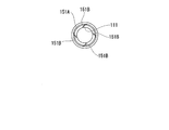
以上において、連通溝35B,72B,73B,91B,92B,36Bを、貫通孔111の径方向に沿って形成したが、これらのうちのいずれか、あるいは全部について、貫通孔111の径方向に対して傾斜させても良い。例えば、図9Aに示す変形例のように貫通孔111及び環状溝151Aの径方向に対して、これらを連通させる連通溝151Bを傾斜させてもよい。このように傾斜させることで回転部分の相対回転を利用して、貫通孔111側のグリスを、連通溝151Bで案内して環状溝151Aに流すことができる。その場合、図9Aに示すように、複数の連通溝151Bを周方向に対して同様に湾曲させてスパイラル状としても良い。
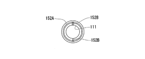
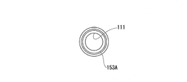
また、以上において、連通溝35B,72B,73B,91B,92B,36Bを、それぞれ四箇所ずつ設けたが、これらは少なくとも一箇所ずつ設けられていれば良い。例えば、図9Bに示す変形例のように、一つの環状溝152Aに対して連通溝152Bを二箇所だけ設けても良い。さらには、連通溝35B,72B,73B,91B,92B,36Bのうちのいずれか、あるいは全部について設けないようにしても良い。つまり、図9Cに示す変形例のように、貫通孔111と環状溝153Aとの間に、これらを連通させる連通溝を設けなくても良い。
また、連通溝35Bを設けずに、環状溝35Aと孔部37との間の全体に、下面35aから環状溝35Aよりも浅く凹む凹状部を設けても良い。同様に、連通溝72Bを設けずに、環状溝72Aと孔部75との間の全体に、上端面72aから環状溝72Aよりも浅く凹む凹状部を設けても良い。同様に、連通溝73Bを設けずに、環状溝73Aと孔部75との間の全体に、下端面73aから環状溝73Aよりも浅く凹む凹状部を設けても良い。同様に、連通溝91Bを設けずに、環状溝91Aと孔部94との間の全体に、上面91aから環状溝91Aよりも浅く凹む凹状部を設けても良い。同様に、連通溝92Bを設けずに、環状溝92Aと孔部94との間の全体に、下端面92aから環状溝92Aよりも浅く凹む凹状部を設けても良い。同様に、連通溝36Bを設けずに、環状溝36Aと孔部38との間の全体に、上面36aから環状溝36Aよりも浅く凹む凹状部を設けても良い。つまり、図10に示す変形例のように、貫通孔111と環状溝154Aとの間全体に、環状溝154Aよりも浅く凹む凹状部155を設ける。
上記実施形態においては、上側支持片部35に環状溝35A及び連通溝35Bを設け、これに対向するレバー14の上側ボス部72に環状溝72A及び連通溝72Bを設けたが、これらのうちのいずれか一方側のみに環状溝及び連通溝を設けても良い。つまり、シリンダボディ11の上側支持片部35とレバー14との間位置に、貫通孔111を囲む環状溝と、この環状溝及び貫通孔111を連通させる連通溝とが設けられていれば良い。
また、レバー14の下側ボス部73に環状溝73A及び連通溝73Bを設け、これに対向するノッカー15の主板部91に環状溝91A及び連通溝91Bを設けたが、これらのうちのいずれか一方側のみに環状溝及び連通溝を設けても良い。つまり、レバー14とノッカー15との間位置に、貫通孔111を囲む環状溝と、この環状溝及び貫通孔111を連通させる連通溝とが設けられていれば良い。
また、ノッカー15のボス部92に環状溝92A及び連通溝92Bを設け、これに対向するシリンダボディ11の下側支持片部36に環状溝36A及び連通溝36Bを設けたが、これらのうちのいずれか一方側のみに環状溝及び連通溝を設けても良い。つまり、ノッカー15とシリンダボディ11の下側支持片部36との間位置に、貫通孔111を囲む環状溝と、この環状溝及び貫通孔111を連通させる連通溝とが設けられていれば良い。
さらに、シリンダボディ11の上側支持片部35とレバー14との間位置、レバー14とノッカー15との間位置、及び、ノッカー15とシリンダボディ11の下側支持片部36との間位置、の三箇所のうちのいずれか一箇所のみに、貫通孔111を囲む環状溝と、この環状溝及び貫通孔111を連通させる連通溝とを設けても良い。あるいは、シリンダボディ11の上側支持片部35とレバー14との間位置、レバー14とノッカー15との間位置、及び、ノッカー15とシリンダボディ11の下側支持片部36との間位置、の三箇所のうちのいずれか二箇所のみに、貫通孔111を囲む環状溝と、この環状溝及び貫通孔111を連通させる連通溝とを設けても良い。つまり、シリンダボディ11の上側支持片部35とレバー14との間位置、レバー14とノッカー15との間位置、及び、ノッカー15とシリンダボディ11の下側支持片部36との間位置、の三箇所のうちの少なくともいずれか一箇所のみに、貫通孔111を囲む環状溝と、この環状溝及び貫通孔111を連通させる連通溝とが設けられていれば良い。
ここで、特に、レバー14とノッカー15との間位置、及び、ノッカー15とシリンダボディ11の下側支持片部36との間位置に設けることが、摩耗抑制効果が高い。その場合、レバー14の下側ボス部73に環状溝73A及び連通溝73Bを設け、これに対向するノッカー15の主板部91に環状溝91A及び連通溝91Bを設け、ノッカー15のボス部92に環状溝92A及び連通溝92Bを設けると効果的である。
上記実施形態は、ステアリンググリップの前方に配置されるレバーと、上記レバーへの操作力をピストンに伝達するノッカーと、上記レバー及び上記ノッカーを跨ぐように配置され、上記ピストンを収容するシリンダボディと、上記レバー、上記ノッカー及び上記シリンダボディを貫通する貫通孔に挿通されて、上記レバー及び上記ノッカーを上記シリンダボディに対して回動可能に支持する支持軸と、を備え、上記シリンダボディと上記レバーとの間位置、上記レバーと上記ノッカーとの間位置、及び、上記ノッカーと上記シリンダボディとの間位置の少なくともいずれか一つの間位置に、上記貫通孔を囲む環状溝が設けられている。
この構成により、環状溝にグリスを溜めることができると共に、環状溝によって、その径方向外側にグリスが流出することを抑制できるため、接触して相対回転する回転部分の摩耗を抑制することが可能となる。
この構成により、環状溝にグリスを溜めることができると共に、環状溝によって、その径方向外側にグリスが流出することを抑制できるため、接触して相対回転する回転部分の摩耗を抑制することが可能となる。
また、上記実施形態では、上記環状溝は、上記ノッカーと上記シリンダボディとの間位置に設けられている。
この構成により、ノッカーがシリンダボディに押し付けられる場合に、これらの間に生じ易い摩耗を抑制することができる。
この構成により、ノッカーがシリンダボディに押し付けられる場合に、これらの間に生じ易い摩耗を抑制することができる。
また、上記実施形態では、上記環状溝は、上記ノッカーの上記シリンダボディ側に設けられるノッカー環状溝と、上記シリンダボディの上記ノッカー側に設けられるシリンダボディ環状溝と、であり、上記シリンダボディ環状溝は、上記ノッカー環状溝よりも大径である。
この構成により、シリンダボディ環状溝によって、その径方向外側にグリスが流出することを抑制することができる。
この構成により、シリンダボディ環状溝によって、その径方向外側にグリスが流出することを抑制することができる。
また、上記実施形態では、上記環状溝と上記貫通孔とを連通させる連通溝が設けられている。
この構成により、貫通孔と支持軸との間のグリスを環状溝に流すことができる。よって、回転部分の摩耗をさらに抑制することが可能となる。
この構成により、貫通孔と支持軸との間のグリスを環状溝に流すことができる。よって、回転部分の摩耗をさらに抑制することが可能となる。
また、上記実施形態では、連通溝は、貫通孔の径方向に対して傾斜している。
この構成により、回転部分の回転を利用してグリスを環状溝に流すことができる。
この構成により、回転部分の回転を利用してグリスを環状溝に流すことができる。
2 ブレーキ用マスタシリンダ
4 ステアリンググリップ
11 シリンダボディ
14 レバー
15 ノッカー
17 支持軸
35A,72A,73A,91A,92A,36A 環状溝
35B,72B,73B,91B,92B,36B 連通溝
51 ピストン
111 貫通孔
4 ステアリンググリップ
11 シリンダボディ
14 レバー
15 ノッカー
17 支持軸
35A,72A,73A,91A,92A,36A 環状溝
35B,72B,73B,91B,92B,36B 連通溝
51 ピストン
111 貫通孔
Claims (5)
- ステアリンググリップの前方に配置されるレバーと、
前記レバーへの操作力をピストンに伝達するノッカーと、
前記レバー及び前記ノッカーを跨ぐように配置され、前記ピストンを収容するシリンダボディと、
前記レバー、前記ノッカー及び前記シリンダボディを貫通する貫通孔に挿通されて、前記レバー及び前記ノッカーを前記シリンダボディに対して回動可能に支持する支持軸と、を備え、
前記シリンダボディと前記レバーとの間位置、前記レバーと前記ノッカーとの間位置、及び、前記ノッカーと前記シリンダボディとの間位置の少なくともいずれか一つの間位置に、前記貫通孔を囲む環状溝が設けられている、ブレーキ用マスタシリンダ。 - 前記環状溝は、前記ノッカーと前記シリンダボディとの間位置に設けられている、請求項1記載のブレーキ用マスタシリンダ。
- 前記環状溝は、前記ノッカーの前記シリンダボディ側に設けられるノッカー環状溝と、前記シリンダボディの前記ノッカー側に設けられるシリンダボディ環状溝と、であり、
前記シリンダボディ環状溝は、前記ノッカー環状溝よりも大径である、請求項2記載のブレーキ用マスタシリンダ。 - 前記環状溝と前記貫通孔とを連通させる連通溝が設けられている、請求項1から3のいずれか一項記載のブレーキ用マスタシリンダ。
- 前記連通溝は、前記貫通孔の径方向に対して傾斜している、請求項4記載のブレーキ用マスタシリンダ。
Priority Applications (1)
| Application Number | Priority Date | Filing Date | Title |
|---|---|---|---|
| JP2019508621A JP6785364B2 (ja) | 2017-03-27 | 2018-01-24 | ブレーキ用マスタシリンダ |
Applications Claiming Priority (2)
| Application Number | Priority Date | Filing Date | Title |
|---|---|---|---|
| JP2017-061325 | 2017-03-27 | ||
| JP2017061325 | 2017-03-27 |
Publications (1)
| Publication Number | Publication Date |
|---|---|
| WO2018179740A1 true WO2018179740A1 (ja) | 2018-10-04 |
Family
ID=63674631
Family Applications (1)
| Application Number | Title | Priority Date | Filing Date |
|---|---|---|---|
| PCT/JP2018/002108 Ceased WO2018179740A1 (ja) | 2017-03-27 | 2018-01-24 | ブレーキ用マスタシリンダ |
Country Status (3)
| Country | Link |
|---|---|
| JP (1) | JP6785364B2 (ja) |
| TW (1) | TWI675775B (ja) |
| WO (1) | WO2018179740A1 (ja) |
Citations (9)
| Publication number | Priority date | Publication date | Assignee | Title |
|---|---|---|---|---|
| JPS56127081U (ja) * | 1980-02-28 | 1981-09-28 | ||
| JPS60117257U (ja) * | 1984-01-18 | 1985-08-08 | 日信工業株式会社 | マスタシリンダ |
| JPH088929Y2 (ja) * | 1990-06-13 | 1996-03-13 | 自動車機器株式会社 | マスタシリンダ |
| JP2772698B2 (ja) * | 1990-02-28 | 1998-07-02 | 日信工業株式会社 | タンデム型マスタシリンダ |
| JP3440373B2 (ja) * | 1996-02-08 | 2003-08-25 | 日信工業株式会社 | バーハンドル車両用操作レバー |
| JP2009202653A (ja) * | 2008-02-26 | 2009-09-10 | Otsuka Koki Co Ltd | 回転中心部の潤滑構造 |
| JP2010156354A (ja) * | 2008-12-26 | 2010-07-15 | Ntn Corp | 軸継手 |
| JP5227872B2 (ja) * | 2008-08-29 | 2013-07-03 | 本田技研工業株式会社 | 車両用連動ブレーキ装置 |
| JP6041305B2 (ja) * | 2012-08-24 | 2016-12-07 | 曙ブレーキ工業株式会社 | 前後連動ブレーキ機構 |
-
2017
- 2017-12-12 TW TW106143458A patent/TWI675775B/zh active
-
2018
- 2018-01-24 WO PCT/JP2018/002108 patent/WO2018179740A1/ja not_active Ceased
- 2018-01-24 JP JP2019508621A patent/JP6785364B2/ja active Active
Patent Citations (9)
| Publication number | Priority date | Publication date | Assignee | Title |
|---|---|---|---|---|
| JPS56127081U (ja) * | 1980-02-28 | 1981-09-28 | ||
| JPS60117257U (ja) * | 1984-01-18 | 1985-08-08 | 日信工業株式会社 | マスタシリンダ |
| JP2772698B2 (ja) * | 1990-02-28 | 1998-07-02 | 日信工業株式会社 | タンデム型マスタシリンダ |
| JPH088929Y2 (ja) * | 1990-06-13 | 1996-03-13 | 自動車機器株式会社 | マスタシリンダ |
| JP3440373B2 (ja) * | 1996-02-08 | 2003-08-25 | 日信工業株式会社 | バーハンドル車両用操作レバー |
| JP2009202653A (ja) * | 2008-02-26 | 2009-09-10 | Otsuka Koki Co Ltd | 回転中心部の潤滑構造 |
| JP5227872B2 (ja) * | 2008-08-29 | 2013-07-03 | 本田技研工業株式会社 | 車両用連動ブレーキ装置 |
| JP2010156354A (ja) * | 2008-12-26 | 2010-07-15 | Ntn Corp | 軸継手 |
| JP6041305B2 (ja) * | 2012-08-24 | 2016-12-07 | 曙ブレーキ工業株式会社 | 前後連動ブレーキ機構 |
Also Published As
| Publication number | Publication date |
|---|---|
| TW201838865A (zh) | 2018-11-01 |
| JPWO2018179740A1 (ja) | 2019-11-07 |
| TWI675775B (zh) | 2019-11-01 |
| JP6785364B2 (ja) | 2020-11-18 |
Similar Documents
| Publication | Publication Date | Title |
|---|---|---|
| CN103693151B (zh) | 机动二轮车的联动制动装置 | |
| TW202144213A (zh) | 液壓裝置 | |
| EP3774511B1 (en) | A braking system for a motor vehicle | |
| CN1696007B (zh) | 自行车用刹车装置 | |
| JP6041305B2 (ja) | 前後連動ブレーキ機構 | |
| JP5856311B2 (ja) | 車両用ペダル装置 | |
| JP2014004958A (ja) | 鞍乗り型車両 | |
| JP2018141480A (ja) | モータサイクル | |
| US11919604B2 (en) | Leaning vehicle | |
| CN108025794B (zh) | 车辆的联动制动装置 | |
| JP6785364B2 (ja) | ブレーキ用マスタシリンダ | |
| CN104704256B (zh) | 制动钳 | |
| JP5816600B2 (ja) | 鞍乗型車両の連動ブレーキ装置 | |
| JP2010270888A (ja) | 鞍乗型車両のブレーキディスク締付け構造 | |
| JP2009250330A (ja) | ブレーキディスク | |
| JP2010235033A (ja) | 鞍乗り型車両の連動ブレーキ装置 | |
| US11987318B2 (en) | Leaning-type vehicle | |
| JP6126632B2 (ja) | 鞍乗り型車両用ブレーキ装置 | |
| WO2022138283A1 (ja) | バーハンドル車両の前部構造 | |
| WO2019235040A1 (ja) | 鞍乗り型車両の連動ブレーキ装置 | |
| JP4212009B2 (ja) | 二輪車のパーキングブレーキ装置 | |
| WO2010137715A1 (ja) | 車両用ディスクブレーキ | |
| JP4620608B2 (ja) | 車両の減速装置及びブレーキ装置取付構造 | |
| JP2016055776A (ja) | 鞍乗り型車両の連動ブレーキ装置 | |
| JP2016017628A (ja) | ドラムブレーキの支持構造 |
Legal Events
| Date | Code | Title | Description |
|---|---|---|---|
| 121 | Ep: the epo has been informed by wipo that ep was designated in this application |
Ref document number: 18776737 Country of ref document: EP Kind code of ref document: A1 |
|
| WWE | Wipo information: entry into national phase |
Ref document number: 2019508621 Country of ref document: JP |
|
| NENP | Non-entry into the national phase |
Ref country code: DE |
|
| 122 | Ep: pct application non-entry in european phase |
Ref document number: 18776737 Country of ref document: EP Kind code of ref document: A1 |