WO2018179484A1 - ギヤ伝動装置 - Google Patents
ギヤ伝動装置 Download PDFInfo
- Publication number
- WO2018179484A1 WO2018179484A1 PCT/JP2017/031426 JP2017031426W WO2018179484A1 WO 2018179484 A1 WO2018179484 A1 WO 2018179484A1 JP 2017031426 W JP2017031426 W JP 2017031426W WO 2018179484 A1 WO2018179484 A1 WO 2018179484A1
- Authority
- WO
- WIPO (PCT)
- Prior art keywords
- tooth
- gear
- region
- tapered
- tooth region
- Prior art date
- Legal status (The legal status is an assumption and is not a legal conclusion. Google has not performed a legal analysis and makes no representation as to the accuracy of the status listed.)
- Ceased
Links
Images




Classifications
-
- F—MECHANICAL ENGINEERING; LIGHTING; HEATING; WEAPONS; BLASTING
- F16—ENGINEERING ELEMENTS AND UNITS; GENERAL MEASURES FOR PRODUCING AND MAINTAINING EFFECTIVE FUNCTIONING OF MACHINES OR INSTALLATIONS; THERMAL INSULATION IN GENERAL
- F16H—GEARING
- F16H1/00—Toothed gearings for conveying rotary motion
- F16H1/02—Toothed gearings for conveying rotary motion without gears having orbital motion
- F16H1/04—Toothed gearings for conveying rotary motion without gears having orbital motion involving only two intermeshing members
- F16H1/06—Toothed gearings for conveying rotary motion without gears having orbital motion involving only two intermeshing members with parallel axes
- F16H1/10—Toothed gearings for conveying rotary motion without gears having orbital motion involving only two intermeshing members with parallel axes one of the members being internally toothed
-
- F—MECHANICAL ENGINEERING; LIGHTING; HEATING; WEAPONS; BLASTING
- F16—ENGINEERING ELEMENTS AND UNITS; GENERAL MEASURES FOR PRODUCING AND MAINTAINING EFFECTIVE FUNCTIONING OF MACHINES OR INSTALLATIONS; THERMAL INSULATION IN GENERAL
- F16H—GEARING
- F16H55/00—Elements with teeth or friction surfaces for conveying motion; Worms, pulleys or sheaves for gearing mechanisms
- F16H55/02—Toothed members; Worms
- F16H55/17—Toothed wheels
- F16H55/18—Special devices for taking up backlash
-
- F—MECHANICAL ENGINEERING; LIGHTING; HEATING; WEAPONS; BLASTING
- F01—MACHINES OR ENGINES IN GENERAL; ENGINE PLANTS IN GENERAL; STEAM ENGINES
- F01L—CYCLICALLY OPERATING VALVES FOR MACHINES OR ENGINES
- F01L1/00—Valve-gear or valve arrangements, e.g. lift-valve gear
- F01L1/34—Valve-gear or valve arrangements, e.g. lift-valve gear characterised by the provision of means for changing the timing of the valves without changing the duration of opening and without affecting the magnitude of the valve lift
- F01L1/344—Valve-gear or valve arrangements, e.g. lift-valve gear characterised by the provision of means for changing the timing of the valves without changing the duration of opening and without affecting the magnitude of the valve lift changing the angular relationship between crankshaft and camshaft, e.g. using helicoidal gear
- F01L1/352—Valve-gear or valve arrangements, e.g. lift-valve gear characterised by the provision of means for changing the timing of the valves without changing the duration of opening and without affecting the magnitude of the valve lift changing the angular relationship between crankshaft and camshaft, e.g. using helicoidal gear using bevel or epicyclic gear
-
- F—MECHANICAL ENGINEERING; LIGHTING; HEATING; WEAPONS; BLASTING
- F16—ENGINEERING ELEMENTS AND UNITS; GENERAL MEASURES FOR PRODUCING AND MAINTAINING EFFECTIVE FUNCTIONING OF MACHINES OR INSTALLATIONS; THERMAL INSULATION IN GENERAL
- F16H—GEARING
- F16H55/00—Elements with teeth or friction surfaces for conveying motion; Worms, pulleys or sheaves for gearing mechanisms
- F16H55/02—Toothed members; Worms
- F16H55/08—Profiling
-
- F—MECHANICAL ENGINEERING; LIGHTING; HEATING; WEAPONS; BLASTING
- F16—ENGINEERING ELEMENTS AND UNITS; GENERAL MEASURES FOR PRODUCING AND MAINTAINING EFFECTIVE FUNCTIONING OF MACHINES OR INSTALLATIONS; THERMAL INSULATION IN GENERAL
- F16H—GEARING
- F16H55/00—Elements with teeth or friction surfaces for conveying motion; Worms, pulleys or sheaves for gearing mechanisms
- F16H55/02—Toothed members; Worms
- F16H55/17—Toothed wheels
-
- F—MECHANICAL ENGINEERING; LIGHTING; HEATING; WEAPONS; BLASTING
- F01—MACHINES OR ENGINES IN GENERAL; ENGINE PLANTS IN GENERAL; STEAM ENGINES
- F01L—CYCLICALLY OPERATING VALVES FOR MACHINES OR ENGINES
- F01L2250/00—Camshaft drives characterised by their transmission means
- F01L2250/02—Camshaft drives characterised by their transmission means the camshaft being driven by chains
-
- F—MECHANICAL ENGINEERING; LIGHTING; HEATING; WEAPONS; BLASTING
- F01—MACHINES OR ENGINES IN GENERAL; ENGINE PLANTS IN GENERAL; STEAM ENGINES
- F01L—CYCLICALLY OPERATING VALVES FOR MACHINES OR ENGINES
- F01L2820/00—Details on specific features characterising valve gear arrangements
- F01L2820/03—Auxiliary actuators
- F01L2820/032—Electric motors
-
- F—MECHANICAL ENGINEERING; LIGHTING; HEATING; WEAPONS; BLASTING
- F16—ENGINEERING ELEMENTS AND UNITS; GENERAL MEASURES FOR PRODUCING AND MAINTAINING EFFECTIVE FUNCTIONING OF MACHINES OR INSTALLATIONS; THERMAL INSULATION IN GENERAL
- F16H—GEARING
- F16H1/00—Toothed gearings for conveying rotary motion
- F16H1/28—Toothed gearings for conveying rotary motion with gears having orbital motion
- F16H1/32—Toothed gearings for conveying rotary motion with gears having orbital motion in which the central axis of the gearing lies inside the periphery of an orbital gear
Definitions
- the present invention relates to a gear transmission that suppresses backlash.
- Patent Document 1 a swing gear rotatably supported on an inclined shaft portion inclined with respect to an input shaft portion, a fixed gear, and an output gear connected to the output shaft portion are coaxial with the axis of the inclined shaft portion.
- a gear transmission technique is shown which is arranged with a core and obtains a greater reduction in rotation of the input shaft.
- the oscillating gear is ring-shaped and teeth are formed at both end edges in the axial direction.
- the same gear is formed on the fixed gear so as to mesh with these teeth, and the output gear is Similarly, teeth are formed.
- a difference is set in the number of teeth of the oscillating gear, the fixed gear, and the output shaft portion, and when the input shaft portion is driven and rotated, one tooth portion of the oscillating gear sequentially meshes with the tooth portion of the fixed gear.
- the other gear of the oscillating gear is sequentially engaged with the teeth of the output gear.
- this Patent Document 1 describes that an appropriate preload is applied to the meshing of the gears in order to reduce backlash.
- an internal gear (a ring gear in the literature) is arranged coaxially with a rotating shaft core, and an external gear (an inner gear in the literature) is arranged in parallel with the rotating shaft core and a coaxial core.
- the technology provided with the eccentric member (eccentric ring in literature) which arrange
- Patent Document 3 a tooth portion of one gear of a pair of gears is formed into a shape in which a butting step portion that extends in a taper shape with respect to a tooth shape of a standard gear is formed. A technique for suppressing backlash by meshing with a tooth-shaped gear) is shown.
- a restricting member is provided in order to cause a displacement due to a force generated in the thrust direction at the gear occlusion position.
- Patent Document 3 is easier to suppress backlash associated with tooth surface wear than the configurations shown in Patent Documents 1 and 2, but the tooth surface wear. I could have imagined that the backlash would expand as the process progressed.
- the characteristic configuration of the gear transmission according to the present invention for achieving the above object is A first tooth portion having a plurality of first tooth portions in which a flat tooth region is formed on one end side in the tooth width direction and a first tapered tooth region is formed on the other side in the tooth width direction.
- the first gear is arranged on the same axis as the second axis of rotation parallel to the first axis of rotation of the first gear, and a spur area is formed on one end side in the tooth width direction and the outer end on the other side in the tooth width direction.
- a second gear having a plurality of second tooth portions formed with a second tapered tooth region whose tooth thickness decreases toward the side;
- the first tapered tooth region and the second tapered tooth region of the second gear are in contact with each other while the spur tooth region of the second tooth portion is engaged with the spur tooth region of the first tooth portion.
- a biasing portion that applies a biasing force in the thrust direction to either one of the first gear and the second gear.
- the first tapered tooth region and the second tapered tooth region can be obtained by engaging the flat tooth region of the second tooth portion with the first tooth portion and causing the biasing force from the biasing portion to act in the thrust direction. Can be brought into contact with each other. Therefore, when one of the first tooth portion and the second tooth portion is worn, the first tapered tooth region and the second tapered tooth region are inserted into each other so as to fill a gap created by the wear.
- the gear and the second gear are relatively displaced along the thrust direction. That is, a gap is created between the first tapered tooth region of the first tooth portion and the second tapered tooth region of the second tooth portion, regardless of the degree of progress of wear between the first tooth portion and the second tooth portion. Without increasing backlash.
- At least one of the spur tooth region of the first gear and the spur tooth region of the second gear may be formed to exceed half of the tooth width of each gear.
- the first tooth portion Torque can be transmitted by contacting the flat tooth region of the second tooth portion and the flat tooth region of the second tooth portion.
- one of the first gear and the second gear is an internal gear in which a plurality of internal teeth are formed on the inner periphery of the annular body, and the other is the internal gear of the internal gear.
- the external gear which formed the some external tooth part meshing with a part in the outer periphery of a cylindrical body may be sufficient.
- At least one of an inclination angle of the tooth surface of the first tapered tooth region with respect to the first rotational axis and an inclination angle of the tooth surface of the second tapered tooth region with respect to the second rotational axis is It may be less than 30 degrees.
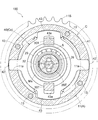
- FIG. 2 is a sectional view taken along line II-II in FIG.
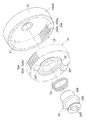
- FIG. 3 is a sectional view taken along line III-III in FIG. 1. It is a disassembled perspective view which shows an output gear, an input gear, and an eccentric member. It is sectional drawing of the occlusion part of an output gear and an input gear. It is a perspective view of the gear transmission of another embodiment (a).
- a drive-side rotator A that rotates synchronously with the crankshaft 1 of the engine E
- a driven-side rotator B that rotates integrally with the intake camshaft 2 around the rotation axis X
- the valve opening / closing timing control device 100 is configured to include a phase adjusting unit C having a gear transmission mechanism so as to set a relative rotational phase between the driving side rotating body A and the driven side rotating body B by the driving force of M. .
- the engine E is configured as a four-cycle type in which pistons 4 are accommodated in a plurality of cylinders 3 formed in a cylinder block, and the pistons 4 are connected to a crankshaft 1 by connecting rods 5.
- a timing chain 6 (or a timing belt or the like) is wound around the output sprocket 1S of the crankshaft 1 of the engine E and the drive sprocket 11S of the drive side rotator A.
- the entire valve opening / closing timing control device 100 rotates about the rotation axis X.
- the phase control motor M drives the phase adjustment unit C to achieve a relative rotational phase displacement that causes the driven-side rotator A to displace the driven-side rotator B in the same or opposite direction as the rotation direction (this operation).
- This operation the same or opposite direction as the rotation direction (this operation).
- Control of the opening / closing timing (opening / closing timing) of the intake valve 2B by the cam portion 2A of the intake camshaft 2 is realized by the displacement of the relative rotational phase.
- the operation in which the driven-side rotator B is displaced in the same direction as the rotation direction of the drive-side rotator A is referred to as an advance angle operation, and the intake air compression ratio is increased by the advance angle operation.
- an operation in which the driven-side rotator B is displaced in the direction opposite to the drive-side rotator A is referred to as retarded angle operation, and the intake air compression ratio is reduced by this retarded angle operation.
- the drive-side rotator A is configured by fastening an outer case 11 having a drive sprocket 11 ⁇ / b> S formed on the outer periphery and a front plate 12 with a plurality of fastening bolts 13.
- the outer case 11 is a bottomed cylindrical mold having an opening at the bottom.
- the intermediate member 20 as the driven-side rotator B and the phase adjuster C having a gear transmission are accommodated in the inner space of the outer case 11.
- the intermediate member 20 constituting the driven side rotating body B includes a support wall portion 21 connected to the intake camshaft 2 in a posture orthogonal to the rotation axis X, and a cylindrical intake camshaft 2 centered on the rotation axis X.
- a cylindrical wall portion 22 that protrudes in a direction away from is integrally formed.
- the intermediate member 20 is fitted in a relatively rotatable manner in a state where the outer peripheral surface of the cylindrical wall portion 22 is in contact with the inner peripheral surface of the outer case 11, and is connected by a connecting bolt 23 that is inserted into the central through hole of the support wall portion 21. It is fixed to the end of the intake camshaft 2.
- the phase control motor M (electric motor) is supported by the engine E by the support frame 7 so that the output shaft Ma is disposed coaxially with the rotary shaft X.
- the output shaft Ma is provided with a pair of engagement pins 8 in a posture orthogonal to the rotation axis X.
- the phase adjustment unit C includes an intermediate member 20, an output gear 25 (an example of a second gear) formed on the inner peripheral surface of the cylindrical wall portion 22 of the intermediate member 20, an eccentric member 26, and the like.
- the output gear 25 is configured as an internal gear in which a plurality of internal teeth 25 ⁇ / b> A (an example of second teeth) is formed on the inner periphery of an annular body centering on the rotation axis X.
- the input gear 30 is configured as an external gear in which a plurality of external tooth portions 30A (an example of a first tooth portion) are formed on the outer periphery of a cylindrical body centered on the eccentric axis Y.
- the number of teeth of the external tooth portion 30A of the input gear 30 is smaller by one than the number of teeth of the internal tooth portion 25A of the output gear 25.
- the phase adjustment unit C is a part of the external gear 30A that is a part of the internal gear 25A of the output gear 25. To bite.
- the eccentric member 26 has a center bearing surface 26S centered on the rotation axis X on the outer end side (the side far from the intake camshaft 2) in the direction along the rotation axis X. Further, the eccentric member 26 is formed with an eccentric bearing surface 26E on the inner end side (side closer to the intake camshaft 2) having an outer peripheral surface centered on the eccentric shaft core Y that is eccentric in a posture parallel to the rotational shaft core X. Has been.
- a pair of engaging grooves 26 ⁇ / b> T that can engage with each of the pair of engaging pins 8 of the phase control motor M (see FIG. 1) are provided on the inner periphery of the eccentric member 26. It is formed in a posture parallel to the core X.
- ball bearings are used for the first bearing 28 and the second bearing 29.
- the inner periphery (inner race) of the first bearing 28 is fitted on the center bearing surface 26S. Further, the outer periphery (outer race) of the first bearing 28 is fitted into the holding space in the center portion of the front plate 12. In this way, the eccentric member 26 is supported so as to be rotatable about the rotation axis X.
- bushes can be used for the first bearing 28 and the second bearing 29.
- the inner circumference (inner race) of the second bearing 29 is fitted on the eccentric bearing surface 26 ⁇ / b> E, and the outer circumference (outer race) of the second bearing 29 is fitted on the inner circumference of the input gear 30. It is crowded.
- the input gear 30 is supported so as to be rotatable about the eccentric axis Y.
- a part of the outer tooth part 30A of the input gear 30 is engaged with a part of the inner tooth part 25A of the output gear 25.
- the internal gear portion 25 ⁇ / b> A of the output gear 25 is a second flat surface parallel to the rotation axis X on the inner end side (side closer to the intake camshaft 2).
- the tooth region 25As and the second tapered tooth region 25At whose tooth thickness (vertical direction in FIG. 5) decreases toward the outer end side (on the side far from the intake camshaft 2) are integrally formed.
- the external gear portion 30A of the input gear 30 (an example of the first gear) includes a first spur tooth region 30As parallel to the eccentric shaft core Y on the inner end side (side closer to the intake camshaft 2), A first tapered tooth region 30At whose tooth thickness increases toward the outer end side is integrally formed on the end side (side far from the intake camshaft 2).
- the first flat tooth region 30As and the second flat tooth region 25As are formed in regions exceeding 50% of the dimension in the tooth width direction (left-right direction in FIG. 5). And as shown in FIG. 5, 1st taper tooth area
- region 25At are formed symmetrically on the basis of the center of tooth thickness. Furthermore, the inclination angle ⁇ (the same angle as the twist angle) of the tooth surfaces of the first tapered tooth region 30At and the second tapered tooth region 25At with respect to the rotation axis X is set to be less than 30 degrees.
- the biasing force of the spring 32 is applied to the inner tooth portion 25A of the output gear 25 so as to shift the outer tooth portion 30A of the input gear 30 in the direction along the rotation axis X (thrust direction).
- a spring 32 is provided so as to be fitted on the eccentric bearing surface 26E of the eccentric member 26, and the urging force of the spring 32 is applied to the inner race of the second bearing 29, whereby the input gear 30 is provided. Shift force is applied to In this embodiment, the compression coil type spring 32 is used as the urging portion, but the urging portion may be a disc spring.
- the Oldham coupling Cx includes a central annular portion 41 and a pair of external engagement arms projecting radially outward from the annular portion 41 along a first direction (left-right direction in FIG. 3). 42 and a plate-like joint member 40 integrally formed with an inner engagement arm 43 projecting radially outward along a direction (vertical direction in FIG. 3) perpendicular to the first direction from the annular portion 41. ing.
- Each of the pair of internal engagement arms 43 is formed with an engagement recess 43 a that is continuous with the opening of the annular portion 41.
- a pair of guides extending in the radial direction about the rotation axis X from the inner space to the outer space of the outer case 11 at the opening edge where the front plate 12 abuts.
- the groove portion 11a is formed in a through groove shape. As shown in FIG. 3, the groove width of the guide groove portion 11 a is set slightly wider than the width of the external engagement arm 42.
- a pair of engaging protrusions 30T are integrally formed on the end face of the input gear 30 facing the front plate 12.
- the engagement width of the engagement protrusion 30 ⁇ / b> T is set to be slightly narrower than the engagement width of the engagement recess 43 a of the internal engagement arm 43.
- the joint member 40 can be displaced in the first direction (left and right direction in FIG. 3) in which the external engagement arm 42 extends with respect to the outer case 11 (see FIG. 1). Further, the input gear 30 can be displaced in the second direction (vertical direction in FIG. 3) along the formation direction of the engagement recess 43 a of the internal engagement arm 43 with respect to the joint member 40.
- valve timing control device 100 In the assembled valve opening / closing timing control device 100, as shown in FIG. 1, a support wall portion 21 of the intermediate member 20 is connected to an end portion of the intake camshaft 2 by a connecting bolt 23, and these rotate integrally.
- the eccentric member 26 is supported by the first bearing 28 so as to be rotatable relative to the front plate 12 about the rotational axis X.
- the input gear 30 is supported via the second bearing 29 with respect to the eccentric bearing surface 26 ⁇ / b> E of the eccentric member 26.
- the input gear 30 is supported so as to be rotatable about the eccentric axis Y, and a part of the outer tooth part 30A is engaged with a part of the inner tooth part 25A of the output gear 25.
- the external engagement arm 42 of the Oldham joint Cx engages with the pair of guide groove portions 11a of the outer case 11, and the input gear 30 enters the engagement recess 43a of the internal engagement arm 43 of the Oldham joint Cx.
- the engaging protrusions 30T are engaged.
- the pair of engaging pins 8 formed on the output shaft Ma of the phase control motor M engages with the engaging groove 26 ⁇ / b> T of the eccentric member 26.
- the biasing force of the spring 32 acts on the input gear 30 in the direction along the rotational axis X (thrust direction) as a whole. Therefore, in a region where a part of the external tooth part 30A of the input gear 30 is engaged with a part of the internal tooth part 25A of the output gear 25, the first part of the external tooth part 30A is in relation to the internal tooth part 25A of the output gear 25.
- the spur tooth region 30As is engaged, and a part of the first tapered tooth region 30At (see FIG. 4) is applied to the outer end portion of the inner tooth portion 25A of the output gear 25 from the direction along the rotation axis X. It will be in contact.
- the first spur tooth region 30As of the input gear 30 and the second spur tooth region 25As of the output gear 25 are engaged, and at the same time, the first tapered tooth of the input gear 30 is engaged.
- the second tapered tooth region 25At of the output gear 25 is engaged with the region 30At, and these tooth surfaces come into contact with each other from the thrust direction.
- phase control motor M (see FIG. 1) is controlled by a control device configured as an ECU (engine control unit).
- the engine E includes sensors (not shown) that can detect the rotational speed (the number of revolutions per unit time) of the crankshaft 1 and the intake camshaft 2 and the respective rotational phases. The detection signals of these sensors are input to the control device.
- the control device maintains the relative rotational phase by driving the phase control motor M at a speed equal to the rotational speed of the intake camshaft 2 when the engine E is in operation.
- the control device performs control to increase or decrease the rotational speed of the phase control motor M with reference to the rotational speed of the intake camshaft 2, thereby realizing the displacement of the relative rotational phase.
- the eccentric shaft core Y rotates the rotational shaft core X in the phase adjustment unit C. Revolve to the center. Due to this revolution, the meshing position of the input gear 30 with respect to the external tooth portion 30 ⁇ / b> A with respect to the internal gear portion 25 ⁇ / b> A of the output gear 25 is displaced along the inner periphery of the output gear 25. Along with this displacement, a rotational force acts between the input gear 30 and the output gear 25. That is, a rotational force centered on the rotational axis X acts on the output gear 25, and a rotational force that attempts to rotate about the eccentric shaft core Y acts on the input gear 30.
- the number of teeth of the external gear portion 30A of the input gear 30 is set to be one less than the number of teeth of the internal gear portion 25A of the output gear 25. Therefore, even when the eccentric shaft core Y of the input gear 30 revolves about one rotation around the rotation shaft X, the output gear 25 rotates only by one tooth angle with respect to the input gear 30 and has a large reduction ratio. Is realized.
- the input gear 30 does not rotate with respect to the outer case 11 because the engaging projection 30T engages with the engaging recess 43a of the internal engaging arm 43 of the joint member 40, and the rotational force is not output to the output gear 25. Act on. Due to the action of the rotational force, the intermediate member 20 together with the output gear 25 rotates about the rotation axis X with respect to the outer case 11. As a result, the relative rotational phase between the driving side rotating body A and the driven side rotating body B is displaced, and the setting of the opening / closing timing by the intake camshaft 2 is realized.
- the first spur tooth region 30As of the input gear 30 and the second spur tooth region 25As of the output gear 25 are engaged, and the first tapered tooth region 30At of the input gear 30 is engaged.
- the second tapered tooth regions 25At of the output gear 25 are in contact with each other from the thrust direction.
- the output gear 25 is displaced along the rotation axis X so as to fill a gap created by the wear. Therefore, the first tapered tooth region 30At of the input gear 30 and the second tapered tooth region 25At of the output gear 25 are maintained in contact with each other in the thrust direction, and the occurrence of backlash is suppressed. Further, with this configuration, it is possible to improve responsiveness in a form in which backlash is packed. Therefore, it is possible to suppress a decrease in responsiveness due to aged wear. Furthermore, when torque is transmitted between the outer tooth portion 30A and the inner tooth portion 25A, the output gear 25 is slightly displaced in the direction along the rotational axis X against the biasing force of the spring 32, so Create a backlash to achieve smooth operation.
- the present invention may be configured as follows (the components having the same functions as those of the embodiments are given the same numbers and symbols as those of the embodiments).
- an externally-driven drive gear 52 (an example of a first gear) that is rotatably arranged around the first axis P1, and is rotatable around the second axis P2.
- the gear transmission is configured by including an externally toothed driven gear 51 (an example of a second gear) and a spring 32 (an example of an urging portion) disposed in the gear.
- the drive gear 52 has a plurality of drive teeth 52A and is spline-fitted to the drive shaft 54 that is rotationally driven.
- the drive gear 52 is supported by the urging force of the spring 32 so as to be shiftable in the direction along the first axis P1 (thrust direction).
- the driven gear 51 has a plurality of driven tooth portions 51A, and is supported so as to rotate integrally with the second shaft P2 and the driven shaft 53 having a coaxial core.
- the driving tooth portion 52A has a main flat tooth region 52As parallel to the first axis P1 and a main tapered tooth region 52At (another example of the first tapered tooth region) whose tooth thickness increases toward one outer end side. Is formed.
- the driven gear 51 includes a follower tooth region 51As parallel to the second axis P2, and a follower taper tooth region 51At (another example of the second taper tooth region) in which the tooth thickness decreases toward the other outer end side. Is formed.
- the drive gear 52 extends along the first axis P1 so as to fill the gap created by this wear. Displace. This displacement maintains the state where the tooth surface of the main tapered tooth region 52At abuts against the tooth surface of the sub taper tooth region 51At in the thrust direction and suppresses the expansion of backlash, thereby improving the responsiveness. Smooth transmission is achieved by suppressing the decrease in responsiveness due to aged wear.
- the tooth thickness is closer to the inner end side with respect to the input gear 30, contrary to the embodiment.
- a taper tooth region to be reduced may be formed, and a taper tooth region in which the tooth thickness increases toward the inner end side with respect to the output gear 25 may be formed.
- the input gear 30 and the output gear 25 are urged in the thrust direction by the urging force of the spring 32, thereby suppressing the backlash expansion and responsiveness. To reduce the responsiveness due to aged wear.
- the tapered tooth region is formed symmetrically with respect to the tooth trace direction.
- the tapered tooth region is formed in an asymmetric shape with respect to the tooth trace direction.
- region only in one side centering on a tooth trace direction may be sufficient.
- a tapered tooth region is formed asymmetrically in this way. It is possible to suppress backlash in accordance with the rotation direction and load. In particular, in this alternative embodiment (c), it is possible to improve responsiveness by closing backlash. Therefore, it is possible to suppress a decrease in responsiveness due to aged wear.
- the eccentric bearing surface 26 ⁇ / b> E of the eccentric member 26 is provided with a spring (recessed spring) that biases the inner tooth portion 25 ⁇ / b> A of the output gear 25 in a direction to engage the outer tooth portion 30 ⁇ / b> A of the input gear 30.
- a spring recessed spring
- a recess is formed in the eccentric bearing surface 26E, and this recess spring is fitted. Then, with this concave spring, the input gear 30 is biased so as to be displaced in the eccentric direction. If it does so, the input gear 30 will be in the state which always applies a pressure from a recessed part spring so that it may displace in an eccentric direction, and suppresses backlash still more favorably.
- (E) Not only for transmitting the driving force, but for example, in order to measure the rotation angle of the rotating system, it is provided in a gear transmission that rotates the potentiometer by increasing the amount of rotation of the rotating system. With such a configuration, the amount of rotation can be increased in a state without backlash to enable detection with high resolution.
- the present invention can be used for a gear transmission having a configuration in which an internal gear and an external gear having a smaller number of teeth are engaged with each other.
Landscapes
- Engineering & Computer Science (AREA)
- General Engineering & Computer Science (AREA)
- Mechanical Engineering (AREA)
- Gears, Cams (AREA)
- Valve Device For Special Equipments (AREA)
- Gear Transmission (AREA)
- Retarders (AREA)
Abstract
長期に亘る使用においてもバックラッシュを良好に抑制するギヤ伝動装置を構成する。ギヤ伝動装置は、歯幅方向で一方に第1平歯領域が形成され他方に外端側ほど歯幅が拡大する第1テーパ歯領域が形成された複数の第1歯部を有する第1ギヤと、歯幅方向で一方に第2平歯領域が形成され他方に外端側ほど歯厚が縮小する第2テーパ歯領域が形成された複数の第2歯部を有する第2ギヤと、第1テーパ歯領域の歯面を第2テーパ歯領域の歯面に当接させるように第1ギヤを回転軸芯に沿う方向に付勢力する付勢部とを備えている。
Description
本発明は、バックラッシュを抑制するギヤ伝動装置に関する。
特許文献1には、入力軸部に対して傾斜する傾斜軸部に回転自在に支持した揺動歯車と、固定歯車と、出力軸部に連結する出力歯車とを傾斜軸部の軸芯と同軸芯で配置し、入力軸部の回転により大きい減速を得るギヤ伝動装置の技術が示されている。
この特許文献1では、揺動歯車がリング状で軸芯方向での両端縁に歯部が形成され、これらの歯部に咬合するように固定歯車に同様の歯部が形成され、出力歯車にも同様に歯部が形成されている。揺動歯車と固定歯車と出力軸部の歯数に差が設定され、入力軸部を駆動回転することにより、揺動歯車の一方の歯部が固定歯車の歯部に順次咬み合い、これと同時に揺動歯車の他方の歯車が出力歯車の歯部に順次咬み合う作動が行われる。このような作動により入力軸部が1回転した際に歯数差に対応する角度だけ出力軸部を回転させる伝動形態となり大減速を実現している。
特に、この特許文献1には、バックラッシュを低減させるため歯車の咬み合いに適切な予圧を与えることが記載されている。
また、特許文献2には、内歯型ギヤ(文献ではリングギヤ)を回転軸芯と同軸芯に配置し、外歯型ギヤ(文献ではインナギヤ)を回転軸芯に平行する偏心軸芯と同軸芯に配置し、外歯型ギヤを、偏心軸芯を中心に回転自在に支持する偏心部材(文献では偏心リング)を備えた技術が示されている。
この特許文献2では、外歯型ギヤを偏心方向に向けて突出付勢するバネ部材を備えることにより、内歯型ギヤの歯部に、外歯型ギヤの歯部が咬合する状態を維持し、バックラッシュに起因した打音を抑制している。
また、特許文献3には、一対の歯車の一方の歯車の歯部が、標準歯車の歯形に対してテーパ状に拡がる突き合わせ段部を形成した形状に形成され、この歯車を他方の歯車(標準歯形の歯車)と咬合させることでバックラッシュを抑制する技術が示されている。
この特許文献3では、歯車の咬合位置においてスラスト方向に発生する力による位置ずれを招くため規制部材を備えている。
ギヤ伝動装置では、特許文献1、2に示されるように歯部の咬み合いを維持するため歯丈方向にバネ等の付勢力を作用させることが一般的に行われる。しかしながら、このように付勢力を作用させる構成であっても、経年変化や、歯面の摩耗に伴いバックラッシュが拡大することもあった。
特に、特許文献1、2に示されるように大きい減速比を得るために歯数を増大した構成では、歯部の歯丈が小さくなり、歯面の摩耗がバックラッシュの拡大に繋がり易いものであった。
このような不都合に対し、特許文献3に示される構成は特許文献1、2に示される構成と比較して歯面の摩耗に伴うバックラッシュの抑制を行い易いものであるが、歯面の摩耗が進行した場合にはバックラッシュが拡大することも想像できた。
このような理由から、長期に亘る使用においてもバックラッシュを良好に抑制するギヤ伝動装置が求められる。
上記目的を達成するための本発明に係るギヤ伝動装置の特徴構成は、
歯幅方向で一方の端部側に平歯領域が形成され歯幅方向で他方に外端側ほど歯厚が拡大する第1テーパ歯領域が形成された複数の第1歯部を有する第1ギヤと、
前記第1ギヤの第1回転軸芯と平行姿勢の第2回転軸芯と同軸芯に配置され、歯幅方向で一方の端部側に平歯領域が形成され歯幅方向で他方に外端側ほど歯厚が縮小する第2テーパ歯領域が形成された複数の第2歯部を有する第2ギヤと、
前記第1歯部の前記平歯領域に前記第2歯部の前記平歯領域が咬合する状態で、前記第1テーパ歯領域と前記第2ギヤの前記第2テーパ歯領域とが当接するように前記第1ギヤと前記第2ギヤとの何れか一方に対してスラスト方向に付勢力を作用させる付勢部と、を備えている点にある。
歯幅方向で一方の端部側に平歯領域が形成され歯幅方向で他方に外端側ほど歯厚が拡大する第1テーパ歯領域が形成された複数の第1歯部を有する第1ギヤと、
前記第1ギヤの第1回転軸芯と平行姿勢の第2回転軸芯と同軸芯に配置され、歯幅方向で一方の端部側に平歯領域が形成され歯幅方向で他方に外端側ほど歯厚が縮小する第2テーパ歯領域が形成された複数の第2歯部を有する第2ギヤと、
前記第1歯部の前記平歯領域に前記第2歯部の前記平歯領域が咬合する状態で、前記第1テーパ歯領域と前記第2ギヤの前記第2テーパ歯領域とが当接するように前記第1ギヤと前記第2ギヤとの何れか一方に対してスラスト方向に付勢力を作用させる付勢部と、を備えている点にある。
この特徴構成によると、第1歯部に第2歯部の平歯領域を咬合させ、付勢部からの付勢力をスラスト方向に作用させることで第1テーパ歯領域と第2テーパ歯領域とを当接させることができる。そのため、第1歯部と第2歯部との一方でも摩耗した場合には、この摩耗により作り出される間隙を埋めるように第1テーパ歯領域と第2テーパ歯領域とが互いに入り込むように第1ギヤと第2ギヤとがスラスト方向に沿って相対変位する。つまり、第1歯部と第2歯部との摩耗の進行の程度に拘わらず、第1歯部の第1テーパ歯領域と第2歯部の第2テーパ歯領域との間に間隙を作ることがなく、バックラッシュの拡大を抑制することができる。また、第1ギヤと第2ギヤとの間でトルクを伝える場合には、付勢部の付勢力に抗して第1ギヤと第2ギヤとがスラスト方向に相対的に離間する方向に僅かに変位し適度のバックラッシュを作り出し円滑な作動を可能にすることができる。
従って、長期に亘る使用においてもバックラッシュを良好に抑制するギヤ伝動装置が構成することができる。
従って、長期に亘る使用においてもバックラッシュを良好に抑制するギヤ伝動装置が構成することができる。
他の構成として、前記第1ギヤの前記平歯領域と前記第2ギヤの前記平歯領域との少なくとも一方が、各々のギヤの歯幅の半分を超えて形成されても良い。
これによると、例えば、負荷が上昇した場合に、付勢部の付勢力に抗して第1ギヤと第2ギヤとが大きく離間する方向に変位する状況であったとしても、第1歯部の平歯領域と、第2歯部の平歯領域とが接触してトルクを伝えることができる。
他の構成として、前記第1ギヤと前記第2ギヤとのうちの一方が環状体の内周に複数の内歯部を形成した内歯ギヤであり、他方が前記内歯ギヤの前記内歯部に咬合する複数の外歯部を円柱状体の外周に形成した外歯ギヤでも良い。
これによると、内歯ギヤと外歯ギヤとの間で回転力を伝えることが可能となる。特に、この構成として例えば、ロボットハンドのように精密な作動が求められる駆動系に内接式遊星ギヤ減速装置を用いても、バックラッシュが抑制されため、ロボットハンドにおいて必要とする精度の作動を可能にすることができる。
他の構成として、前記第1テーパ歯領域の歯面の前記第1回転軸芯に対する傾斜角と、前記第2テーパ歯領域の歯面の前記第2回転軸芯に対する傾斜角との少なくとも一方が30度未満であっても良い。
これによると、30度は緩やかに傾斜する角度であるため、少なくとも一方の傾斜角が30度未満であれば、付勢部の付勢力により第1テーパ歯領域と第2テーパ歯領域と咬み合い状態に維持することができる。
以下、本発明の実施形態を図面に基づいて説明する。
〔基本構成〕
図1に示すように、エンジンEのクランクシャフト1と同期回転する駆動側回転体Aと、回転軸芯Xを中心にして吸気カムシャフト2と一体回転する従動側回転体Bと、位相制御モータMの駆動力により駆動側回転体Aと従動側回転体Bとの相対回転位相を設定するようにギヤ伝動機構を有する位相調節部Cとを備えて弁開閉時期制御装置100が構成されている。
〔基本構成〕
図1に示すように、エンジンEのクランクシャフト1と同期回転する駆動側回転体Aと、回転軸芯Xを中心にして吸気カムシャフト2と一体回転する従動側回転体Bと、位相制御モータMの駆動力により駆動側回転体Aと従動側回転体Bとの相対回転位相を設定するようにギヤ伝動機構を有する位相調節部Cとを備えて弁開閉時期制御装置100が構成されている。
エンジンEは、シリンダブロックに形成された複数のシリンダ3にピストン4を収容し、そのピストン4をコネクティングロッド5によりクランクシャフト1に連結した4サイクル型に構成されている。このエンジンEのクランクシャフト1の出力スプロケット1Sと、駆動側回転体Aの駆動スプロケット11Sとに亘ってタイミングチェーン6(タイミングベルト等でも良い)が巻回されている。
これによりエンジンEの稼働時には弁開閉時期制御装置100の全体が回転軸芯Xを中心に回転する。また、位相制御モータMの駆動により位相調節部Cが駆動側回転体Aに対して従動側回転体Bを回転方向と同方向又は逆方向に変位させる相対回転位相の変位が実現する(この作動形態については後述する)。この相対回転位相の変位により、吸気カムシャフト2のカム部2Aによる吸気バルブ2Bの開閉時期(開閉タイミング)の制御が実現される。
尚、従動側回転体Bが駆動側回転体Aの回転方向と同方向に変位する作動を進角作動と称し、この進角作動により吸気圧縮比が増大する。また、従動側回転体Bが駆動側回転体Aと逆方向に変位する作動(前述と逆方向への作動)を遅角作動と称し、この遅角作動により吸気圧縮比が低減する。
〔弁開閉時期制御装置〕
図1に示すように、駆動側回転体Aは、外周に駆動スプロケット11Sが形成されたアウタケース11と、フロントプレート12とを複数の締結ボルト13で締結して構成されている。アウタケース11は、底部に開口を有する有底筒状型である。
図1に示すように、駆動側回転体Aは、外周に駆動スプロケット11Sが形成されたアウタケース11と、フロントプレート12とを複数の締結ボルト13で締結して構成されている。アウタケース11は、底部に開口を有する有底筒状型である。
アウタケース11の内部空間に従動側回転体Bとしての中間部材20と、ギヤ伝動装置を有した位相調節部Cとが収容されている。
従動側回転体Bを構成する中間部材20は、回転軸芯Xに直交する姿勢で吸気カムシャフト2に連結する支持壁部21と、回転軸芯Xを中心とする筒状で吸気カムシャフト2から離間する方向に突出する筒状壁部22とが一体形成されている。
この中間部材20は、筒状壁部22の外周面がアウタケース11の内周面に接触する状態で相対回転自在に嵌め込まれ、支持壁部21の中央の貫通孔に挿通する連結ボルト23により吸気カムシャフト2の端部に固定される。
位相制御モータM(電動モータ)は、その出力軸Maを回転軸芯Xと同軸芯上に配置するように支持フレーム7によりエンジンEに支持されている。出力軸Maには回転軸芯Xに対して直交する姿勢の一対の係合ピン8が設けられている。
〔位相調節部〕
図1に示すように位相調節部Cは、中間部材20と、中間部材20の筒状壁部22の内周面に形成される出力ギヤ25(第2ギヤの一例)と、偏心部材26と、第1軸受28と、第2軸受29と、入力ギヤ30(第1ギヤの一例)と、付勢部としての圧縮コイル型のスプリング32と、オルダム継手Cxとを備えている。
図1に示すように位相調節部Cは、中間部材20と、中間部材20の筒状壁部22の内周面に形成される出力ギヤ25(第2ギヤの一例)と、偏心部材26と、第1軸受28と、第2軸受29と、入力ギヤ30(第1ギヤの一例)と、付勢部としての圧縮コイル型のスプリング32と、オルダム継手Cxとを備えている。
図1、図2に示すように、出力ギヤ25は回転軸芯Xを中心とする環状体の内周に複数の内歯部25A(第2歯部の一例)を形成した内歯ギヤとして構成されている。入力ギヤ30は偏心軸芯Yを中心とする円柱状体の外周に複数の外歯部30A(第1歯部の一例)を形成した外歯ギヤとして構成されている。
この位相調節部Cでは、入力ギヤ30の外歯部30Aの歯数が、出力ギヤ25の内歯部25Aの歯数より1歯だけ少ない。そして、位相調節部Cは、後述するように入力ギヤ30が偏心軸芯Yを中心に回転自在に支持されることから外歯部30Aの一部が出力ギヤ25の内歯部25Aの一部に咬合する。
偏心部材26は、回転軸芯Xに沿う方向での外端側(吸気カムシャフト2から遠い側)に回転軸芯Xを中心とする中心軸受面26Sが形成されている。また、偏心部材26は、内端側(吸気カムシャフト2に近い側)には回転軸芯Xに平行となる姿勢で偏心する偏心軸芯Yを中心とする外周面の偏心軸受面26Eが形成されている。
図1、4に示すように、偏心部材26の内周には、位相制御モータM(図1参照)の一対の係合ピン8の各々が係合可能な一対の係合溝26Tが回転軸芯Xと平行姿勢で形成されている。
図1に示すように、第1軸受28と第2軸受29とにはボールベアリングが用いられている。そして、第1軸受28の内周(インナーレース)を中心軸受面26Sに外嵌している。さらに、この第1軸受28の外周(アウターレース)をフロントプレート12の中央部分の保持空間に嵌め込んでいる。このようにして、偏心部材26が回転軸芯Xを中心に回転自在に支持される。この弁開閉時期制御装置100では第1軸受28と第2軸受29とにブッシュを用いることも可能である。
また、図2に示すように、第2軸受29の内周(インナーレース)を偏心軸受面26Eに外嵌し、この第2軸受29の外周(アウターレース)を入力ギヤ30の内周に嵌め込んでいる。これにより入力ギヤ30は、偏心軸芯Yを中心に回転自在に支持される。このように、入力ギヤ30が偏心位置に配置される結果、入力ギヤ30の外歯部30Aの一部が出力ギヤ25の内歯部25Aの一部に咬合する。
図4、図5に示すように、出力ギヤ25(第2ギヤの一例)の内歯部25Aは、内端側(吸気カムシャフト2に近い側)に回転軸芯Xと平行する第2平歯領域25Asと、外端側(吸気カムシャフト2から遠い側)に外端側ほど歯厚(図5では上下方向)が縮小する第2テーパ歯領域25Atとが一体形成されている。
これに対し、入力ギヤ30(第1ギヤの一例)の外歯部30Aは、内端側(吸気カムシャフト2に近い側)に偏心軸芯Yと平行する第1平歯領域30Asと、外端側(吸気カムシャフト2から遠い側)に外端側ほど歯厚が拡大する第1テーパ歯領域30Atとが一体形成されている。
尚、第1平歯領域30Asと第2平歯領域25Asとは、歯幅方向(図5では左右方向)での寸法の50%を超える領域に形成されている。そして、図5に示すように、第1テーパ歯領域30Atと第2テーパ歯領域25Atとは、歯厚の中央を基準として対称に形成されている。さらに、第1テーパ歯領域30Atと第2テーパ歯領域25Atとの歯面の回転軸芯Xに対する傾斜角θ(ねじれ角と同様の角度)が、30度未満に設定されている。
更に、出力ギヤ25の内歯部25Aに対して、入力ギヤ30の外歯部30Aを回転軸芯Xに沿う方向(スラスト方向)にシフトさせるようにスプリング32の付勢力を作用させている。具体的な構成として、偏心部材26の偏心軸受面26Eに外嵌するようにスプリング32を備えており、このスプリング32の付勢力を第2軸受29のインナーレースに作用させることにより、入力ギヤ30にシフト力を作用させている。尚、本実施形態では付勢部として圧縮コイル型のスプリング32を用いているが、付勢部が皿バネであっても良い。
〔位相調節部:オルダム継手〕
図3に示すように、オルダム継手Cxは、中央の環状部41と、この環状部41から第1方向(図3では左右方向)に沿って径方向外方に突出する一対の外部係合アーム42と、環状部41から第1方向に直交する方向(図3では上下方向)に沿って径方向外方に突出する内部係合アーム43とを一体形成した板状の継手部材40で構成されている。一対の内部係合アーム43の各々には環状部41の開口に連なる係合凹部43aが形成されている。
図3に示すように、オルダム継手Cxは、中央の環状部41と、この環状部41から第1方向(図3では左右方向)に沿って径方向外方に突出する一対の外部係合アーム42と、環状部41から第1方向に直交する方向(図3では上下方向)に沿って径方向外方に突出する内部係合アーム43とを一体形成した板状の継手部材40で構成されている。一対の内部係合アーム43の各々には環状部41の開口に連なる係合凹部43aが形成されている。
図1に示すように、アウタケース11のうち、フロントプレート12が当接する開口縁部にはアウタケース11の内部空間から外部空間に亘り、回転軸芯Xを中心に半径方向に伸びる一対の案内溝部11aが貫通溝状に形成されている。図3に示すように、この案内溝部11aの溝幅が外部係合アーム42の幅より僅かに広く設定されている。
また、図1に示すように、入力ギヤ30のうちフロントプレート12に対向する端面には一対の係合突起30Tが一体形成されている。図3に示すように、この係合突起30Tの係合幅が内部係合アーム43の係合凹部43aの係合幅より僅かに狭く設定されている。
尚、図3に示すように、継手部材40がアウタケース11(図1参照)に対して外部係合アーム42が伸びる第1方向(図3で左右方向)に変位可能となる。また、この継手部材40に対して内部係合アーム43の係合凹部43aの形成方向に沿う第2方向(図3では上下方向)に入力ギヤ30が変位自在となる。
〔弁開閉時期制御装置の各部の配置〕
組み立て状態の弁開閉時期制御装置100は、図1に示すように吸気カムシャフト2の端部に中間部材20の支持壁部21が連結ボルト23により連結しており、これらは一体回転する。偏心部材26は第1軸受28によりフロントプレート12に対し回転軸芯Xを中心に相対回転自在に支持される。図1、図3に示すように、偏心部材26の偏心軸受面26Eに対し第2軸受29を介して入力ギヤ30が支持されている。これにより入力ギヤ30は偏心軸芯Yを中心に回転自在に支持されると共に、外歯部30Aの一部が出力ギヤ25の内歯部25Aの一部に咬み合う。
組み立て状態の弁開閉時期制御装置100は、図1に示すように吸気カムシャフト2の端部に中間部材20の支持壁部21が連結ボルト23により連結しており、これらは一体回転する。偏心部材26は第1軸受28によりフロントプレート12に対し回転軸芯Xを中心に相対回転自在に支持される。図1、図3に示すように、偏心部材26の偏心軸受面26Eに対し第2軸受29を介して入力ギヤ30が支持されている。これにより入力ギヤ30は偏心軸芯Yを中心に回転自在に支持されると共に、外歯部30Aの一部が出力ギヤ25の内歯部25Aの一部に咬み合う。
また、図3に示すようにオルダム継手Cxの外部係合アーム42がアウタケース11の一対の案内溝部11aに係合し、オルダム継手Cxの内部係合アーム43の係合凹部43aに入力ギヤ30の係合突起30Tが係合する。
更に、図1に示すように、位相制御モータMの出力軸Maに形成された一対の係合ピン8が、偏心部材26の係合溝26Tに係合する。
スプリング32の付勢力が、入力ギヤ30を全体的に回転軸芯Xに沿う方向(スラスト方向)に作用する。そのため、入力ギヤ30の外歯部30Aの一部が出力ギヤ25の内歯部25Aの一部に咬み合う領域においては、出力ギヤ25の内歯部25Aに対して外歯部30Aの第1平歯領域30Asが咬み合うと共に、この出力ギヤ25の内歯部25Aの外端部に対して、第1テーパ歯領域30At(図4参照)の一部が回転軸芯Xに沿う方向から当接する状態となる。
特に、この咬合状態では、図5に示すように、入力ギヤ30の第1平歯領域30Asと、出力ギヤ25の第2平歯領域25Asとが咬合すると同時に、入力ギヤ30の第1テーパ歯領域30Atに対して、出力ギヤ25の第2テーパ歯領域25Atが咬合し、且つ、これらの歯面がスラスト方向から互いに当接する状態となる。
〔位相調節部の作動形態〕
図面には示していないが、位相制御モータM(図1参照)は、ECU(エンジンコントロールユニット)として構成される制御装置によって制御される。
図1に示すように、エンジンEにはクランクシャフト1と吸気カムシャフト2との回転速度(単位時間あたりの回転数)と、各々の回転位相とを検知可能なセンサ(図示せず)を備えており、これらのセンサの検知信号が制御装置に入力する。
図面には示していないが、位相制御モータM(図1参照)は、ECU(エンジンコントロールユニット)として構成される制御装置によって制御される。
図1に示すように、エンジンEにはクランクシャフト1と吸気カムシャフト2との回転速度(単位時間あたりの回転数)と、各々の回転位相とを検知可能なセンサ(図示せず)を備えており、これらのセンサの検知信号が制御装置に入力する。
制御装置は、エンジンEの稼動時において位相制御モータMを吸気カムシャフト2の回転速度と等しい速度で駆動することで相対回転位相を維持する。これに対して制御装置が、位相制御モータMの回転速度を吸気カムシャフト2の回転速度を基準に増大する又は低減する制御を行うことにより相対回転位相の変位が実現する。
位相制御モータMがアウタケース11と等速(吸気カムシャフト2と等速)で回転する場合には、出力ギヤ25の内歯部25Aに対する入力ギヤ30の外歯部30Aの咬み合い位置が変化しないため、駆動側回転体Aに対する従動側回転体Bの相対回転位相は維持される。
これに対して、制御装置が、アウタケース11の回転速度より高速又は低速で位相制御モータMの出力軸Maを駆動回転することにより、位相調節部Cでは偏心軸芯Yが回転軸芯Xを中心に公転する。この公転により出力ギヤ25の内歯部25Aに対する入力ギヤ30の外歯部30Aに対する咬み合い位置が出力ギヤ25の内周に沿って変位する。そしてこの変位に伴い、入力ギヤ30と出力ギヤ25との間には回転力が作用する。つまり、出力ギヤ25には回転軸芯Xを中心とする回転力が作用し、入力ギヤ30には偏心軸芯Yを中心に自転させようとする回転力が作用する。
前述したように入力ギヤ30の外歯部30Aの歯数が、出力ギヤ25の内歯部25Aの歯数より1歯だけ少なく設定されている。そのため、入力ギヤ30の偏心軸芯Yが回転軸芯Xを中心に1回転だけ公転した場合でも、出力ギヤ25は入力ギヤ30に対して1歯の角度だけ回転するに過ぎず大きい減速比での伝動が実現する。
また、入力ギヤ30は、その係合突起30Tが継手部材40の内部係合アーム43の係合凹部43aに係合するためアウタケース11に対して自転することはなく、回転力が出力ギヤ25に作用する。この回転力の作用により出力ギヤ25と共に中間部材20が、アウタケース11に対し回転軸芯Xを中心に回転する。その結果、駆動側回転体Aと従動側回転体Bとの相対回転位相を変位させ、吸気カムシャフト2による開閉時期の設定を実現する。
尚、入力ギヤ30の偏心軸芯Yが回転軸芯Xを中心に公転する際には、入力ギヤ30の変位に伴い、オルダム継手Cxの継手部材40は、アウタケース11に対して外部係合アーム42(図4参照)が伸びる方向(第1方向)に変位し、入力ギヤ30は、内部係合アーム43が伸びる方向(第2方向)へ変位する。
前述したように、位相調節部Cでは、入力ギヤ30の第1平歯領域30Asと、出力ギヤ25の第2平歯領域25Asとが咬合し、入力ギヤ30の第1テーパ歯領域30Atに対して出力ギヤ25の第2テーパ歯領域25Atがスラスト方向から互いに当接する状態にある。
このため、外歯部30Aと内歯部25Aとの一方でも摩耗した場合には、この摩耗によって作り出される間隙を埋めるように出力ギヤ25が回転軸芯Xに沿って変位する。したがって、入力ギヤ30の第1テーパ歯領域30Atと出力ギヤ25の第2テーパ歯領域25Atとをスラスト方向で互いに当接する状態に維持することになりバックラッシュの発生が抑制される。また、この構成ではバックラッシュを詰める形態で応答性の向上を図ることが可能となる。そのため、経年摩耗による応答性の低下も抑制することができる。更に、外歯部30Aと内歯部25Aとの間でトルクを伝える場合には、スプリング32の付勢力に抗して、出力ギヤ25が回転軸芯Xに沿う方向に僅かに変位し適度のバックラッシュを作り出して円滑な作動を実現する。
〔別実施形態〕
本発明は、上記した実施形態以外に以下のように構成しても良い(実施形態と同じ機能を有するものには、実施形態と共通の番号、符号を付している)。
本発明は、上記した実施形態以外に以下のように構成しても良い(実施形態と同じ機能を有するものには、実施形態と共通の番号、符号を付している)。
(a)図6に示すように、第1軸芯P1を中心に回転自在に配置される外歯型の駆動ギヤ52(第1ギヤの一例)と、第2軸芯P2を中心に回転自在に配置される外歯型の従動ギヤ51(第2ギヤの一例)と、スプリング32(付勢部の一例)とを備えてギヤ伝動装置を構成する。
この別実施形態(a)では、駆動ギヤ52は、複数の駆動歯部52Aを有しており、回転駆動される駆動軸54に対してスプライン嵌合している。また、この駆動ギヤ52は、スプリング32の付勢力により第1軸芯P1に沿う方向(スラスト方向)にシフト可能に支持されている。従動ギヤ51は、複数の従動歯部51Aを有しており、第2軸芯P2と同軸芯の従動軸53と一体回転するように支持されている。
駆動歯部52Aは、第1軸芯P1と平行する主平歯領域52Asと、一方の外端側ほど歯厚が拡大する主テーパ歯領域52At(第1テーパ歯領域の別の例)とが形成されている。また、従動ギヤ51は、第2軸芯P2と平行する従平歯領域51Asと、他方の外端側ほど歯厚が縮小する従テーパ歯領域51At(第2テーパ歯領域の別の例)とが形成されている。
これにより、駆動ギヤ52の主平歯領域52Asと従動ギヤ51の従平歯領域51Asが咬合すると同時に、スプリング32の付勢力により従動歯部51Aの従テーパ歯領域51Atの歯面に対して、駆動歯部52Aの主テーパ歯領域52Atの歯面がスラスト方向に当接する状態が維持される。
そして、駆動ギヤ52の駆動歯部52Aと従動ギヤ51の従動歯部51Aとの何れが摩耗した場合でも、この摩耗によって作り出される間隙を埋めるように駆動ギヤ52が第1軸芯P1に沿って変位する。この変位により、従テーパ歯領域51Atの歯面に対して主テーパ歯領域52Atの歯面がスラスト方向に当接する状態を維持し、バックラッシュの拡大を抑制することで、応答性の向上を図り、経年摩耗による応答性の低下を抑制して円滑な伝動を実現する。
(b)実施形態と同様に外歯型の入力ギヤ30と、内歯型の出力ギヤ25とを有する構成において、実施形態とは逆に、入力ギヤ30に対して内端側ほど歯厚が縮小するテーパ歯領域を形成し、出力ギヤ25に対して内端側ほど歯厚が拡大するテーパ歯領域とを形成しても良い。このような構成であっても実施形態に示した構成と同様にスプリング32の付勢力によって入力ギヤ30と出力ギヤ25とをスラスト方向に付勢することによりバックラッシュの拡大を抑制して応答性の向上を図り、経年摩耗による応答性の低下を抑制する。
(c)実施形態では、歯筋方向を基準としてテーパ歯領域を対称に形成していたが、これに代えて、例えば、歯筋方向を基準に非対称となる形状にテーパ歯領域を形成することや、歯筋方向を中央として、一方の側だけにテーパ歯領域を形成する構成であっても良い。
つまり、ギヤ伝動装置として歯車が決まった方向にだけ回転するものや、決まった方向に回転した場合にのみ大きい負荷が作用するギヤ伝動装置では、このように非対称にテーパ歯領域を形成することにより、回転方向や負荷に対応してバックラッシュの抑制が可能となる。特に、この別実施形態(c)ではバックラッシュを詰めることで、応答性の向上を図ることが可能となる。そのため、経年摩耗による応答性の低下を抑制することができる。
(d)実施形態において出力ギヤ25の内歯部25Aに対して、入力ギヤ30の外歯部30Aを咬合させる方向に付勢するバネ(凹部バネ)を偏心部材26の偏心軸受面26Eに備える。具体的な構成としては、偏心軸受面26Eに凹部を形成し、この凹部バネを嵌め込む。そして、この凹部バネで、入力ギヤ30を偏心方向に変位するように付勢する。そうすると、入力ギヤ30は、偏心方向に変位するように凹部バネから常に圧力を作用させる状態となり、一層良好にバックラッシュを抑制する。
(e)駆動力を伝動するものに限らず、例えば、回転系の回転角度を計測するため、回転系の回転量を増大してポテンショメータを回転操作するギヤ伝動装置に備える。このように構成したものでは、バックラッシュのない状態で回転量を拡大し高い分解能での検知を可能にする。
本発明は、内歯型ギヤと、これより歯数が少ない外歯型ギヤとを咬合させた構成のギヤ伝動装置に利用することができる。
25 出力ギヤ(第2ギヤ)
25A 内歯部(第2歯部)
25As 第2平歯領域
25At 第2テーパ歯領域
30 入力ギヤ(第1ギヤ)
30A 外歯ギヤ(第1歯部)
30As 第1平歯領域
30At 第1テーパ歯領域
32 スプリング(付勢部)
51 従動ギヤ(第2ギヤ)
51A 従動歯部(第2歯部)
51As 従平歯領域
51At 従テーパ歯領域(第2テーパ歯領域)
52 駆動ギヤ(第1ギヤ)
52A 駆動歯部(第1歯部)
52As 主平歯領域
52At 主テーパ歯領域(第1テーパ歯領域)
θ 傾斜角
25A 内歯部(第2歯部)
25As 第2平歯領域
25At 第2テーパ歯領域
30 入力ギヤ(第1ギヤ)
30A 外歯ギヤ(第1歯部)
30As 第1平歯領域
30At 第1テーパ歯領域
32 スプリング(付勢部)
51 従動ギヤ(第2ギヤ)
51A 従動歯部(第2歯部)
51As 従平歯領域
51At 従テーパ歯領域(第2テーパ歯領域)
52 駆動ギヤ(第1ギヤ)
52A 駆動歯部(第1歯部)
52As 主平歯領域
52At 主テーパ歯領域(第1テーパ歯領域)
θ 傾斜角
Claims (4)
- 歯幅方向で一方の端部側に平歯領域が形成され歯幅方向で他方に外端側ほど歯厚が拡大する第1テーパ歯領域が形成された複数の第1歯部を有する第1ギヤと、
前記第1ギヤの第1回転軸芯と平行姿勢の第2回転軸芯と同軸芯に配置され、歯幅方向で一方の端部側に平歯領域が形成され歯幅方向で他方に外端側ほど歯厚が縮小する第2テーパ歯領域が形成された複数の第2歯部を有する第2ギヤと、
前記第1歯部の前記平歯領域に前記第2歯部の前記平歯領域が咬合する状態で、前記第1テーパ歯領域と前記第2ギヤの前記第2テーパ歯領域とが当接するように前記第1ギヤと前記第2ギヤとの何れか一方に対してスラスト方向に付勢力を作用させる付勢部と、を備えているギヤ伝動装置。 - 前記第1ギヤの前記平歯領域と前記第2ギヤの前記平歯領域との少なくとも一方が、各々のギヤの歯幅の半分を超えて形成されている請求項1に記載のギヤ伝動装置。
- 前記第1ギヤと前記第2ギヤとのうちの一方が環状体の内周に複数の内歯部を形成した内歯ギヤであり、他方が前記内歯ギヤの前記内歯部に咬合する複数の外歯部を円柱状体の外周に形成した外歯ギヤである請求項1又は2に記載のギヤ伝動装置。
- 前記第1テーパ歯領域の歯面の前記第1回転軸芯に対する傾斜角と、前記第2テーパ歯領域の歯面の前記第2回転軸芯に対する傾斜角との少なくとも一方が30度未満である請求項1から3のいずれか一項に記載のギヤ伝動装置。
Priority Applications (1)
| Application Number | Priority Date | Filing Date | Title |
|---|---|---|---|
| US16/479,794 US20200182331A1 (en) | 2017-03-28 | 2017-08-31 | Gear transmission device |
Applications Claiming Priority (2)
| Application Number | Priority Date | Filing Date | Title |
|---|---|---|---|
| JP2017062864A JP2018165531A (ja) | 2017-03-28 | 2017-03-28 | ギヤ伝動装置 |
| JP2017-062864 | 2017-03-28 |
Publications (1)
| Publication Number | Publication Date |
|---|---|
| WO2018179484A1 true WO2018179484A1 (ja) | 2018-10-04 |
Family
ID=63674842
Family Applications (1)
| Application Number | Title | Priority Date | Filing Date |
|---|---|---|---|
| PCT/JP2017/031426 Ceased WO2018179484A1 (ja) | 2017-03-28 | 2017-08-31 | ギヤ伝動装置 |
Country Status (3)
| Country | Link |
|---|---|
| US (1) | US20200182331A1 (ja) |
| JP (1) | JP2018165531A (ja) |
| WO (1) | WO2018179484A1 (ja) |
Families Citing this family (7)
| Publication number | Priority date | Publication date | Assignee | Title |
|---|---|---|---|---|
| JP7198099B2 (ja) * | 2019-02-01 | 2022-12-28 | 株式会社デンソー | バルブタイミング調整装置 |
| JP7226780B2 (ja) * | 2019-03-15 | 2023-02-21 | 株式会社Soken | バルブタイミング調整装置 |
| DE112020004671T5 (de) * | 2019-09-30 | 2022-06-15 | Denso Corporation | Untersetzungsgetriebe und Motor mit Untersetzungsgetriebe |
| JP7074115B2 (ja) * | 2019-09-30 | 2022-05-24 | 株式会社デンソー | 減速機及び減速機付モータ |
| JP7131520B2 (ja) * | 2019-09-30 | 2022-09-06 | 株式会社デンソー | 減速機及び減速機付モータ |
| JP7074114B2 (ja) * | 2019-09-30 | 2022-05-24 | 株式会社デンソー | 減速機及び減速機付モータ |
| CN114922947B (zh) * | 2022-06-13 | 2023-03-21 | 三联传动机械有限公司 | 一种用于圆切机的减速机构 |
Citations (2)
| Publication number | Priority date | Publication date | Assignee | Title |
|---|---|---|---|---|
| JP2007303612A (ja) * | 2006-05-12 | 2007-11-22 | Enplas Corp | 歯車装置 |
| JP2016044627A (ja) * | 2014-08-25 | 2016-04-04 | アイシン精機株式会社 | 弁開閉時期制御装置 |
-
2017
- 2017-03-28 JP JP2017062864A patent/JP2018165531A/ja active Pending
- 2017-08-31 US US16/479,794 patent/US20200182331A1/en not_active Abandoned
- 2017-08-31 WO PCT/JP2017/031426 patent/WO2018179484A1/ja not_active Ceased
Patent Citations (2)
| Publication number | Priority date | Publication date | Assignee | Title |
|---|---|---|---|---|
| JP2007303612A (ja) * | 2006-05-12 | 2007-11-22 | Enplas Corp | 歯車装置 |
| JP2016044627A (ja) * | 2014-08-25 | 2016-04-04 | アイシン精機株式会社 | 弁開閉時期制御装置 |
Also Published As
| Publication number | Publication date |
|---|---|
| JP2018165531A (ja) | 2018-10-25 |
| US20200182331A1 (en) | 2020-06-11 |
Similar Documents
| Publication | Publication Date | Title |
|---|---|---|
| JP2018165531A (ja) | ギヤ伝動装置 | |
| JP2016044627A (ja) | 弁開閉時期制御装置 | |
| JP6838506B2 (ja) | 弁開閉時期制御装置 | |
| JP6790639B2 (ja) | 弁開閉時期制御装置 | |
| JP6790640B2 (ja) | 弁開閉時期制御装置 | |
| JP4390078B2 (ja) | バルブタイミング調整装置 | |
| JP2019007409A (ja) | 弁開閉時期制御装置 | |
| JP4442574B2 (ja) | バルブタイミング調整装置 | |
| JP6869465B2 (ja) | ギヤ減速装置 | |
| JP6443382B2 (ja) | バルブタイミング調整装置 | |
| JP4760953B2 (ja) | バルブタイミング調整装置 | |
| JP7353789B2 (ja) | 波動歯車ユニット、歯車変速装置及びバルブタイミング変更装置 | |
| WO2018092390A1 (ja) | 弁開閉時期制御装置 | |
| JP6394222B2 (ja) | 弁開閉時期制御装置 | |
| JP5139209B2 (ja) | 可変バルブタイミング装置 | |
| JP2019157679A (ja) | 弁開閉時期制御装置 | |
| JP2015102064A (ja) | 弁開閉時期制御装置 | |
| JP7161917B2 (ja) | 位相変更ユニット及びバルブタイミング変更装置 | |
| JP2828361B2 (ja) | バルブタイミング調整装置 | |
| JP7198099B2 (ja) | バルブタイミング調整装置 | |
| JP4419092B2 (ja) | バルブタイミング調整装置 | |
| JP7368152B2 (ja) | バルブタイミング調整装置 | |
| JP4915006B2 (ja) | 内燃機関の制御時間を変化させる装置 | |
| JP7131445B2 (ja) | バルブタイミング調整装置 | |
| JP2015102065A (ja) | 弁開閉時期制御装置 |
Legal Events
| Date | Code | Title | Description |
|---|---|---|---|
| 121 | Ep: the epo has been informed by wipo that ep was designated in this application |
Ref document number: 17902864 Country of ref document: EP Kind code of ref document: A1 |
|
| NENP | Non-entry into the national phase |
Ref country code: DE |
|
| 122 | Ep: pct application non-entry in european phase |
Ref document number: 17902864 Country of ref document: EP Kind code of ref document: A1 |