WO2018168747A1 - Buse de chambre de combustion, chambre de combustion, et turbine à gaz - Google Patents
Buse de chambre de combustion, chambre de combustion, et turbine à gaz Download PDFInfo
- Publication number
- WO2018168747A1 WO2018168747A1 PCT/JP2018/009444 JP2018009444W WO2018168747A1 WO 2018168747 A1 WO2018168747 A1 WO 2018168747A1 JP 2018009444 W JP2018009444 W JP 2018009444W WO 2018168747 A1 WO2018168747 A1 WO 2018168747A1
- Authority
- WO
- WIPO (PCT)
- Prior art keywords
- air
- fuel
- combustor
- nozzle
- passage
- Prior art date
Links
Images


Classifications
-
- F—MECHANICAL ENGINEERING; LIGHTING; HEATING; WEAPONS; BLASTING
- F23—COMBUSTION APPARATUS; COMBUSTION PROCESSES
- F23R—GENERATING COMBUSTION PRODUCTS OF HIGH PRESSURE OR HIGH VELOCITY, e.g. GAS-TURBINE COMBUSTION CHAMBERS
- F23R3/00—Continuous combustion chambers using liquid or gaseous fuel
- F23R3/02—Continuous combustion chambers using liquid or gaseous fuel characterised by the air-flow or gas-flow configuration
- F23R3/04—Air inlet arrangements
- F23R3/045—Air inlet arrangements using pipes
-
- F—MECHANICAL ENGINEERING; LIGHTING; HEATING; WEAPONS; BLASTING
- F23—COMBUSTION APPARATUS; COMBUSTION PROCESSES
- F23R—GENERATING COMBUSTION PRODUCTS OF HIGH PRESSURE OR HIGH VELOCITY, e.g. GAS-TURBINE COMBUSTION CHAMBERS
- F23R3/00—Continuous combustion chambers using liquid or gaseous fuel
- F23R3/28—Continuous combustion chambers using liquid or gaseous fuel characterised by the fuel supply
- F23R3/286—Continuous combustion chambers using liquid or gaseous fuel characterised by the fuel supply having fuel-air premixing devices
-
- F—MECHANICAL ENGINEERING; LIGHTING; HEATING; WEAPONS; BLASTING
- F23—COMBUSTION APPARATUS; COMBUSTION PROCESSES
- F23R—GENERATING COMBUSTION PRODUCTS OF HIGH PRESSURE OR HIGH VELOCITY, e.g. GAS-TURBINE COMBUSTION CHAMBERS
- F23R3/00—Continuous combustion chambers using liquid or gaseous fuel
- F23R3/02—Continuous combustion chambers using liquid or gaseous fuel characterised by the air-flow or gas-flow configuration
- F23R3/16—Continuous combustion chambers using liquid or gaseous fuel characterised by the air-flow or gas-flow configuration with devices inside the flame tube or the combustion chamber to influence the air or gas flow
- F23R3/18—Flame stabilising means, e.g. flame holders for after-burners of jet-propulsion plants
- F23R3/22—Flame stabilising means, e.g. flame holders for after-burners of jet-propulsion plants movable, e.g. to an inoperative position; adjustable, e.g. self-adjusting
-
- F—MECHANICAL ENGINEERING; LIGHTING; HEATING; WEAPONS; BLASTING
- F02—COMBUSTION ENGINES; HOT-GAS OR COMBUSTION-PRODUCT ENGINE PLANTS
- F02C—GAS-TURBINE PLANTS; AIR INTAKES FOR JET-PROPULSION PLANTS; CONTROLLING FUEL SUPPLY IN AIR-BREATHING JET-PROPULSION PLANTS
- F02C3/00—Gas-turbine plants characterised by the use of combustion products as the working fluid
- F02C3/04—Gas-turbine plants characterised by the use of combustion products as the working fluid having a turbine driving a compressor
-
- F—MECHANICAL ENGINEERING; LIGHTING; HEATING; WEAPONS; BLASTING
- F02—COMBUSTION ENGINES; HOT-GAS OR COMBUSTION-PRODUCT ENGINE PLANTS
- F02C—GAS-TURBINE PLANTS; AIR INTAKES FOR JET-PROPULSION PLANTS; CONTROLLING FUEL SUPPLY IN AIR-BREATHING JET-PROPULSION PLANTS
- F02C3/00—Gas-turbine plants characterised by the use of combustion products as the working fluid
- F02C3/14—Gas-turbine plants characterised by the use of combustion products as the working fluid characterised by the arrangement of the combustion chamber in the plant
-
- F—MECHANICAL ENGINEERING; LIGHTING; HEATING; WEAPONS; BLASTING
- F02—COMBUSTION ENGINES; HOT-GAS OR COMBUSTION-PRODUCT ENGINE PLANTS
- F02C—GAS-TURBINE PLANTS; AIR INTAKES FOR JET-PROPULSION PLANTS; CONTROLLING FUEL SUPPLY IN AIR-BREATHING JET-PROPULSION PLANTS
- F02C3/00—Gas-turbine plants characterised by the use of combustion products as the working fluid
- F02C3/20—Gas-turbine plants characterised by the use of combustion products as the working fluid using a special fuel, oxidant, or dilution fluid to generate the combustion products
- F02C3/24—Gas-turbine plants characterised by the use of combustion products as the working fluid using a special fuel, oxidant, or dilution fluid to generate the combustion products the fuel or oxidant being liquid at standard temperature and pressure
-
- F—MECHANICAL ENGINEERING; LIGHTING; HEATING; WEAPONS; BLASTING
- F02—COMBUSTION ENGINES; HOT-GAS OR COMBUSTION-PRODUCT ENGINE PLANTS
- F02C—GAS-TURBINE PLANTS; AIR INTAKES FOR JET-PROPULSION PLANTS; CONTROLLING FUEL SUPPLY IN AIR-BREATHING JET-PROPULSION PLANTS
- F02C7/00—Features, components parts, details or accessories, not provided for in, or of interest apart form groups F02C1/00 - F02C6/00; Air intakes for jet-propulsion plants
- F02C7/04—Air intakes for gas-turbine plants or jet-propulsion plants
-
- F—MECHANICAL ENGINEERING; LIGHTING; HEATING; WEAPONS; BLASTING
- F02—COMBUSTION ENGINES; HOT-GAS OR COMBUSTION-PRODUCT ENGINE PLANTS
- F02C—GAS-TURBINE PLANTS; AIR INTAKES FOR JET-PROPULSION PLANTS; CONTROLLING FUEL SUPPLY IN AIR-BREATHING JET-PROPULSION PLANTS
- F02C7/00—Features, components parts, details or accessories, not provided for in, or of interest apart form groups F02C1/00 - F02C6/00; Air intakes for jet-propulsion plants
- F02C7/22—Fuel supply systems
- F02C7/222—Fuel flow conduits, e.g. manifolds
-
- F—MECHANICAL ENGINEERING; LIGHTING; HEATING; WEAPONS; BLASTING
- F23—COMBUSTION APPARATUS; COMBUSTION PROCESSES
- F23R—GENERATING COMBUSTION PRODUCTS OF HIGH PRESSURE OR HIGH VELOCITY, e.g. GAS-TURBINE COMBUSTION CHAMBERS
- F23R3/00—Continuous combustion chambers using liquid or gaseous fuel
- F23R3/02—Continuous combustion chambers using liquid or gaseous fuel characterised by the air-flow or gas-flow configuration
- F23R3/04—Air inlet arrangements
- F23R3/10—Air inlet arrangements for primary air
- F23R3/12—Air inlet arrangements for primary air inducing a vortex
- F23R3/14—Air inlet arrangements for primary air inducing a vortex by using swirl vanes
-
- F—MECHANICAL ENGINEERING; LIGHTING; HEATING; WEAPONS; BLASTING
- F23—COMBUSTION APPARATUS; COMBUSTION PROCESSES
- F23R—GENERATING COMBUSTION PRODUCTS OF HIGH PRESSURE OR HIGH VELOCITY, e.g. GAS-TURBINE COMBUSTION CHAMBERS
- F23R3/00—Continuous combustion chambers using liquid or gaseous fuel
- F23R3/02—Continuous combustion chambers using liquid or gaseous fuel characterised by the air-flow or gas-flow configuration
- F23R3/16—Continuous combustion chambers using liquid or gaseous fuel characterised by the air-flow or gas-flow configuration with devices inside the flame tube or the combustion chamber to influence the air or gas flow
- F23R3/18—Flame stabilising means, e.g. flame holders for after-burners of jet-propulsion plants
- F23R3/24—Flame stabilising means, e.g. flame holders for after-burners of jet-propulsion plants of the fluid-screen type
-
- F—MECHANICAL ENGINEERING; LIGHTING; HEATING; WEAPONS; BLASTING
- F23—COMBUSTION APPARATUS; COMBUSTION PROCESSES
- F23R—GENERATING COMBUSTION PRODUCTS OF HIGH PRESSURE OR HIGH VELOCITY, e.g. GAS-TURBINE COMBUSTION CHAMBERS
- F23R3/00—Continuous combustion chambers using liquid or gaseous fuel
- F23R3/28—Continuous combustion chambers using liquid or gaseous fuel characterised by the fuel supply
- F23R3/30—Continuous combustion chambers using liquid or gaseous fuel characterised by the fuel supply comprising fuel prevapourising devices
- F23R3/32—Continuous combustion chambers using liquid or gaseous fuel characterised by the fuel supply comprising fuel prevapourising devices being tubular
-
- F—MECHANICAL ENGINEERING; LIGHTING; HEATING; WEAPONS; BLASTING
- F23—COMBUSTION APPARATUS; COMBUSTION PROCESSES
- F23R—GENERATING COMBUSTION PRODUCTS OF HIGH PRESSURE OR HIGH VELOCITY, e.g. GAS-TURBINE COMBUSTION CHAMBERS
- F23R3/00—Continuous combustion chambers using liquid or gaseous fuel
- F23R3/28—Continuous combustion chambers using liquid or gaseous fuel characterised by the fuel supply
- F23R3/36—Supply of different fuels
-
- F—MECHANICAL ENGINEERING; LIGHTING; HEATING; WEAPONS; BLASTING
- F23—COMBUSTION APPARATUS; COMBUSTION PROCESSES
- F23R—GENERATING COMBUSTION PRODUCTS OF HIGH PRESSURE OR HIGH VELOCITY, e.g. GAS-TURBINE COMBUSTION CHAMBERS
- F23R3/00—Continuous combustion chambers using liquid or gaseous fuel
- F23R3/42—Continuous combustion chambers using liquid or gaseous fuel characterised by the arrangement or form of the flame tubes or combustion chambers
- F23R3/44—Combustion chambers comprising a single tubular flame tube within a tubular casing
-
- F—MECHANICAL ENGINEERING; LIGHTING; HEATING; WEAPONS; BLASTING
- F05—INDEXING SCHEMES RELATING TO ENGINES OR PUMPS IN VARIOUS SUBCLASSES OF CLASSES F01-F04
- F05D—INDEXING SCHEME FOR ASPECTS RELATING TO NON-POSITIVE-DISPLACEMENT MACHINES OR ENGINES, GAS-TURBINES OR JET-PROPULSION PLANTS
- F05D2220/00—Application
- F05D2220/30—Application in turbines
- F05D2220/32—Application in turbines in gas turbines
-
- F—MECHANICAL ENGINEERING; LIGHTING; HEATING; WEAPONS; BLASTING
- F05—INDEXING SCHEMES RELATING TO ENGINES OR PUMPS IN VARIOUS SUBCLASSES OF CLASSES F01-F04
- F05D—INDEXING SCHEME FOR ASPECTS RELATING TO NON-POSITIVE-DISPLACEMENT MACHINES OR ENGINES, GAS-TURBINES OR JET-PROPULSION PLANTS
- F05D2240/00—Components
- F05D2240/35—Combustors or associated equipment
-
- F—MECHANICAL ENGINEERING; LIGHTING; HEATING; WEAPONS; BLASTING
- F05—INDEXING SCHEMES RELATING TO ENGINES OR PUMPS IN VARIOUS SUBCLASSES OF CLASSES F01-F04
- F05D—INDEXING SCHEME FOR ASPECTS RELATING TO NON-POSITIVE-DISPLACEMENT MACHINES OR ENGINES, GAS-TURBINES OR JET-PROPULSION PLANTS
- F05D2260/00—Function
- F05D2260/20—Heat transfer, e.g. cooling
- F05D2260/213—Heat transfer, e.g. cooling by the provision of a heat exchanger within the cooling circuit
Definitions
- the present invention relates to a combustor nozzle, a combustor, and a gas turbine.
- a premixed combustion method is widely used in which fuel is mixed with compressed air (combustion air) sent from a compressor in advance to generate an air-fuel mixture, and this air-fuel mixture is combusted.
- compressed air combustion air
- this type of combustor one having a second fuel nozzle provided on the central axis of the combustor and a plurality of first fuel nozzles arranged in parallel with the second fuel nozzle is known. .
- Patent Document 1 discloses a technique for suppressing the occurrence of flashback by reducing the fuel concentration while reducing the region where the flow rate of the air-fuel mixture is low by ejecting air from the tip of the first fuel nozzle. Has been.
- the present invention is directed to a combustor nozzle, a combustor, and a gas turbine that can suppress the flame from going up toward the tip of the nozzle when a backfire occurs and can reduce the influence of heat on the fuel.
- the purpose is to provide.
- the combustor nozzle includes a nozzle body extending along the axis, and the nozzle body is formed along the axis, and the first fuel passage through which the first fuel flows. And extending from the first fuel passage toward the front end side toward the outer peripheral surface of the nozzle body, and ejecting the first fuel from the outer peripheral surface, and more than the first fuel passage.
- An air flow passage extending in the axial direction on the outer side in the radial direction of the axis and through which purge air flows, and extending from the air flow passage toward the center of the tip of the nozzle body, and ejecting purge air from the center of the tip An air ejection path.
- the purge air is ejected from the center of the tip of the nozzle body, so that in the combustor provided with the combustor nozzle, fuel and compressed air are mixed in the vicinity of the tip of the combustor nozzle.
- the fuel concentration in the air-fuel mixture can be reduced. This makes it difficult for a flame to occur at the tip of the nozzle.
- the flow rate of the air-fuel mixture at the tip of the nozzle is increased by the jetted purge air. Thereby, when backfire occurs, it becomes difficult for the flame to go up toward the tip of the nozzle.
- the first fuel passage is arranged radially inward of the air flow passage, the first fuel is kept away from the high-temperature compressed air flowing around the nozzle body, and the influence of the heat on the first fuel is affected. Can be reduced.
- the air flow passage may be an annular passage extending in a circumferential direction, and the first fuel passage may be disposed radially inward of the air flow passage.
- the influence of heat on the first fuel flowing through the first fuel passage can be further reduced.
- the air flow amount can be increased by increasing the cross-sectional area of the air flow passage.
- the combustor nozzle may include an air heat insulating layer provided between the air flow passage and the first fuel passage.
- the influence of heat on the first fuel flowing through the first fuel passage can be further reduced.
- the nozzle for a combustor has a plurality of the first fuel ejection paths, and the air ejection paths include a plurality of upstream air ejection paths connected to the air flow path and a plurality of the upstream air ejection paths.
- An air cavity connected to the downstream side, and a downstream air ejection path connecting the air cavity and the center of the tip of the nozzle body, and the first fuel ejection path and the upstream air ejection path The positions in the circumferential direction are different and may intersect when viewed from the radial direction.
- the purge air can be ejected from the center of the tip of the nozzle body without causing the upstream air ejection path and the first fuel ejection path to interfere with each other.
- the combustor nozzle includes a second fuel passage through which a second fuel flows radially outward of the first fuel flow passage, the first fuel is an oil fuel, and the second fuel is a gas It may be fuel.
- Such a configuration can be applied to a dual type combustor in which the nozzle for the combustor can be switched to oil fuel or gas fuel. Moreover, coking of oil fuel can be suppressed by arrange
- the combustor nozzle may include an air intake portion that connects the outer peripheral surface of the nozzle body and the air flow passage to take in purge air from the outer peripheral surface of the nozzle body.
- the combustor holds the combustor nozzle and between the inner cylinder through which the compressed air circulates toward the downstream side and the inner cylinder.
- An outer cylinder that defines a compressed air flow path that inverts at the end and introduces compressed air to the downstream side, a turning vane that is provided on the outer peripheral surface of the nozzle body and rectifies the compressed air that is reversed,
- the air intake part is formed on the upstream side of the turning vane.
- compressed air with higher pressure can be taken into the air intake section as purge air.
- the air intake portion may be formed on a radially outer side centering on a central axis of the inner cylinder.
- the compressed air that is reversed and flows radially inward can be taken in efficiently.
- the combustor holds the combustor nozzle and between the inner cylinder through which the compressed air circulates toward the downstream side and the inner cylinder.
- An outer cylinder that defines a compressed air flow path that inverts at the end and introduces compressed air toward the downstream side, an air supply means that generates compressed air, and compressed air generated by the air supply means And an air introduction part that supplies the air flow passage.
- the purge air can be stably supplied to the air flow passage regardless of the operation state of the gas turbine.
- a gas turbine includes a compressor that generates compressed air obtained by compressing air, the combustor, and a turbine driven by the combustion gas, and the air supply means. Has an extraction part for extracting compressed air generated by the compressor.
- the purge air can be generated by extracting the compressed air generated by the compressor without providing a separate device for generating the purge air supplied to the air flow passage.
- the influence of heat on the first fuel can be reduced by moving the first fuel away from the high-temperature compressed air flowing around the nozzle body.
- FIG. 5 is a cross-sectional view taken along the line VV in FIG. 4, illustrating the arrangement of the first fuel ejection path and the upstream air ejection path of the first fuel nozzle. It is sectional drawing of the 1st fuel nozzle of 2nd embodiment of this invention.
- the gas turbine 100 combusts a mixture gas of a compressor 51 that compresses the outside air Ao to generate compressed air A, and the compressed air A and the fuel F to burn the combustion gas G.
- the compressor 51 includes a compressor rotor 56 that rotates about the gas turbine axis Ar, a compressor casing 57 that rotatably covers the compressor rotor 56, and a plurality of compressor vane rows 58. .
- the compressor rotor 56 includes a compressor rotor shaft 59 extending along the gas turbine axis Ar and a plurality of compressor blade rows 60 attached to the compressor rotor shaft 59.
- the plurality of compressor rotor cascades 60 are arranged in the axial direction of the gas turbine axis Ar.
- Each compressor moving blade row 60 is composed of a plurality of moving blades arranged in the circumferential direction of the gas turbine axis Ar.
- a compressor stationary blade row 58 is disposed on each downstream side of the plurality of compressor moving blade rows 60.
- Each compressor stationary blade row 58 is fixed inside the compressor casing 57.
- Each compressor stationary blade row 58 is composed of a plurality of stationary blades arranged in the circumferential direction of the gas turbine axis Ar.
- the turbine 53 includes a turbine rotor 61 that rotates about the gas turbine axis Ar, a turbine casing 62 that rotatably covers the turbine rotor 61, and a plurality of turbine stationary blade rows 63.
- the turbine rotor 61 includes a turbine rotor shaft 64 extending along the gas turbine axis Ar, and a plurality of turbine rotor blade rows 65 attached to the turbine rotor shaft 64.
- the plurality of turbine rotor blade rows 65 are arranged in the axial direction of the gas turbine axis Ar.
- Each turbine rotor blade row 65 is composed of a plurality of rotor blades arranged in the circumferential direction of the gas turbine axis Ar.
- a turbine stationary blade row 63 is arranged on each upstream side of the plurality of turbine blade rows 65.
- Each turbine stationary blade row 63 is fixed inside the turbine casing 62.
- Each turbine stationary blade row 63 is composed of a plurality of stationary blades arranged in the circumferential direction of the gas turbine axis Ar.
- the gas turbine 100 further includes a cylindrical intermediate casing 67 around the gas turbine axis Ar.
- the intermediate casing 67 is disposed between the compressor casing 57 and the turbine casing 62 in the axial direction of the gas turbine axis Ar.
- the compressor rotor 56 and the turbine rotor 61 are located on the same gas turbine axis Ar, and are connected to each other to form a gas turbine rotor 68.
- a rotor of a generator GEN is connected to the gas turbine rotor 68.
- the combustor 10 generates high-temperature and high-pressure combustion gas G by supplying fuel F to the compressed air A compressed by the compressor 51.
- the combustor 10 of the present embodiment is a dual type combustor that can be switched to oil fuel or gas fuel.
- the plurality of combustors 10 are fixed to the intermediate casing 67 at intervals in the circumferential direction of the gas turbine axis Ar.
- the combustor 10 includes a combustor main body 11 and a combustion cylinder 69.
- the combustion cylinder 69 functions as a combustion chamber in which the supplied fuel F and compressed air A are reacted.
- the combustion cylinder 69 increases the flow velocity of the combustion gas G flowing from the combustor body 11 and introduces it into the turbine 53 in the downstream.
- the outside air Ao taken into the compressor 51 passes through the plurality of compressor stationary blade rows 58 and the compressor moving blade row 60 and is compressed to become high-temperature and high-pressure compressed air A.
- the compressed air A is mixed with the fuel F in the combustor 10 and burned, whereby a high-temperature and high-pressure combustion gas G is generated.
- the combustion gas G passes through the turbine stationary blade row 63 and the turbine rotor blade row 65 of the turbine 53, so that the turbine rotor shaft 64 is rotationally driven, and rotational power is supplied to the generator GEN connected to the gas turbine rotor 68. Power is generated by granting.
- the cooling device 54 is a device that extracts a part of the compressed air A supplied to the combustor 10 and compresses it again to cool the cooling target of the gas turbine 100.
- the object to be cooled is a component that is exposed to a high temperature.
- the cooling device 54 includes an extraction unit 72 for extracting a part of the compressed air A, a cooler 73 for cooling the extracted compressed air A, and further compressing the compressed air A cooled by the cooler 73 to purge air PA
- the air introduction unit 76 includes a manifold 77 and an air introduction pipe 78.
- the air introduction pipe 78 is connected to the air flow passage 24 (see FIG. 3) of the first fuel nozzle 1.
- Compressed air A compressed again by the forced air-cooled compressor 74 is supplied to the first fuel nozzle 1 through the air introduction unit 76 as purge air PA.
- the purge air PA may be supplied to another cooling target of the gas turbine 100, for example, a stationary blade as cooling air.
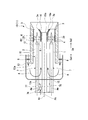
- the combustor main body 11 includes a cylindrical inner cylinder 12, and an outer cylinder 13 provided coaxially with the central axis Ac of the inner cylinder 12 on the outer peripheral side of the inner cylinder 12. Yes. Between the outer cylinder 13 and the inner cylinder 12, there is formed a compressed air flow path R1 for introducing the compressed air A so as to be reversed at the end 12a of the inner cylinder 12 toward the downstream Da2.
- the compressed air A that has flowed into the combustor main body 11 from between the outer cylinder 13 and the inner cylinder 12 turns 180 ° at the end wall 13 a of the outer cylinder 13 and is supplied into the inner cylinder 12.
- the combustor body 11 includes a second fuel nozzle 15 and a first fuel nozzle 1 in the inner cylinder 12.
- a third fuel nozzle 8 for injecting fuel into the compressed air flow path R1 is provided on the inner peripheral surface of the outer cylinder 13.
- the third fuel nozzle 8 is formed so as to protrude from the inner peripheral surface of the outer cylinder 13 toward the central axis Ac of the inner cylinder 12.
- the third fuel nozzle 8 is connected to a fuel supply source (not shown). The fuel is mixed with the compressed air A in the compressed air flow path R1.
- the second fuel nozzle 15 is provided along the central axis Ac of the inner cylinder 12.
- the second fuel nozzle 15 injects fuel F supplied from outside and ignites the fuel F to generate a flame.
- the second fuel nozzle 15 includes a pilot cone 16.
- the pilot cone 16 is formed in a cylindrical shape surrounding the outer peripheral side of the tip portion 15 a of the second fuel nozzle 15.
- the pilot cone 16 has a tapered cone portion 16a whose inner diameter gradually increases from the vicinity of the tip portion 15a of the second fuel nozzle 15 in the flame generation direction.
- the tapered cone portion 16a regulates the flame diffusion range and direction, and enhances flame holding properties.
- a plurality of first fuel nozzles 1 are provided in the inner cylinder 12.
- the first fuel nozzles 1 are arranged on the outer peripheral side of the second fuel nozzle 15 (radially outward with the central axis Ac as the center) with a gap in the circumferential direction.
- Each first fuel nozzle 1 extends parallel to the central axis Ac of the inner cylinder 12.
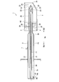
- the first fuel nozzle 1 includes a first fuel nozzle main body 2, a cone member 3, and a swirl vane 4 provided between the first fuel nozzle main body 2 and the cone member 3.
- the direction in which the axis Am of the first fuel nozzle 1 extends is defined as the axis direction Da.
- a direction perpendicular to the axis Am is defined as a radial direction, a side away from the axis Am in the radial direction is referred to as a radially outer side, and a side closer to the axis Am in the radial direction is referred to as a radially inner side.
- the base end side of the first fuel nozzle 1 is referred to as an upstream side Da1 (left side in FIG. 2), and the tip side of the first fuel nozzle 1 is referred to as a downstream side Da2 (right side in FIG. 2).
- the first fuel nozzle body 2 is a substantially cylindrical member that extends along the axis Am.
- the first fuel nozzle body 2 connects the first fuel nozzle base 2a on the downstream Da2, the first fuel nozzle tip 2c on the upstream Da1, and the first fuel nozzle base 2a and the first fuel nozzle body 2 part. And a first fuel nozzle taper portion 2b.
- the outer diameter of the first fuel nozzle base 2a is larger than the outer diameter of the first fuel nozzle tip 2c.
- the first fuel nozzle taper portion 2b is formed so as to be gradually reduced in diameter toward the downstream Da2 so as to smoothly connect the first fuel nozzle base portion 2a and the first fuel nozzle tip portion 2c.
- the first fuel nozzle tip 2c has a substantially conical shape whose outer diameter gradually decreases toward the downstream Da2.
- the first fuel nozzle tip 2c is formed with a plurality of first fuel ejection holes 23 (see FIG. 3) for ejecting oil fuel.
- An air ejection hole 26 for ejecting air is formed in the center of the tip of the first fuel nozzle tip 2c.
- the cone member 3 is provided on the outer peripheral side of the first fuel nozzle tip 2c.
- the cone member 3 is cylindrical and is provided so as to surround the first fuel nozzle tip 2c of the first fuel nozzle body 2 from the outer peripheral side.
- the cone member 3 is formed such that the side 3a close to the pilot cone 16 on the center side of the inner cylinder 12 is gradually inclined toward the outer peripheral side in the flame generation direction.
- the cone member 3 forms a main flow path R ⁇ b> 2 through which the compressed air A flows with the first fuel nozzle 1.
- the plurality of swirl blades 4 impart swirl force to the flow in the main flow path R2.
- a plurality of second fuel ejection holes 29 for ejecting the gas fuel F ⁇ b> 2 are formed in the plurality of swirl vanes 4.
- Oil fuel F ⁇ b> 1 or gas fuel F ⁇ b> 2 is supplied into the first fuel nozzle 1, and gas fuel F ⁇ b> 2 is supplied from the first fuel nozzle 1 to the swirl blade 4.
- Each swirl vane 4 projects radially from the outer peripheral surface of the first fuel nozzle 1 and is connected to the inner peripheral surface of the cone member 3.
- the swirl vane 4 is formed to swirl the compressed air A flowing to the downstream side Da2 around the axis Am.
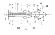
- the first fuel nozzle body 2 includes three fuel tanks connected to the first fuel passage 21 into which the oil fuel F ⁇ b> 1 as the first fuel is introduced and the downstream Da ⁇ b> 2 of the first fuel passage 21.
- a first fuel ejection path 22 (only two are shown in FIG. 3), an air flow path 24 into which purge air PA is introduced, an air ejection path 25 connected to the downstream side Da2 of the air flow path 24,
- a second fuel passage 27 into which gas fuel F2 as the second fuel is introduced, a second fuel passage 27, and a second fuel ejection passage 28 connecting the second fuel ejection holes 29 are provided.
- the first fuel passage 21 is formed along the axis Am at the radial center position of the first fuel nozzle body 2.
- the first fuel passage 21 is disposed on the axis Am of the first fuel nozzle body 2.
- the first fuel ejection path 22 extends to the outer peripheral surface 2 f of the first fuel nozzle body 2 as it goes toward the distal end side of the first fuel nozzle body 2.
- the first fuel ejection path 22 is connected to a first fuel ejection hole 23 opened on the outer peripheral surface 2 f of the first fuel nozzle body 2.
- oil fuel F1 flows as the first fuel.
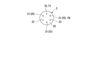
- the three first fuel ejection paths 22 are provided at equal intervals in the circumferential direction around the axis Am. Each first fuel ejection path 22 is inclined so as to gradually go outward in the radial direction toward the downstream side Da2.
- the oil fuel F1 supplied to the first fuel passage 21 is divided into three first fuel ejection paths 22 and ejected from the first fuel ejection holes 23.
- the number of the first fuel ejection paths 22 is not limited to three.
- the air flow passage 24 is an annular passage that is disposed radially outside the first fuel passage 21 and extends in the axial direction Da.
- the air flow passage 24 has an annular cross-sectional shape viewed from the axial direction Da.
- the air flow passage 24 extends from the first fuel nozzle base 2a of the first fuel nozzle body 2 to the first fuel nozzle tip 2c.
- An air introduction hole 30 that connects the air flow passage 24 and the outer peripheral surface of the first fuel nozzle body 2 is formed in the vicinity of the downstream Da2 end of the first fuel nozzle base 2a.
- the air introduction hole 30 extends from the air flow passage 24 toward the central axis Ac (see FIG. 2) of the inner cylinder 12 of the combustor 10.
- the purge air PA is supplied to the air flow passage 24 through the air introduction portion 76 and the air introduction hole 30 of the cooling device 54.
- the air ejection path 25 is a flow path connecting the air flow passage 24 and the air ejection hole 26. As shown in FIG. 4, the air ejection path 25 includes three upstream air ejection paths 31 (only two are shown in FIG. 4) connected to the air flow path 24 and three upstream air ejection paths 31.
- the air cavity 32 is connected to the downstream side Da2, the air cavity 32, and the downstream air ejection path 33 that connects the air ejection holes 26.
- the three upstream air ejection paths 31 are provided at equal intervals in the circumferential direction around the axis Am.
- the upstream air ejection path 31 is formed along the outer peripheral surface of the first fuel nozzle body 2.
- the upstream air ejection path 31 intersects the first fuel ejection path 22 when viewed from the radial direction.
- the air cavity 32 is a space formed on the upstream side Da ⁇ b> 1 from the first fuel injection hole 23.
- the downstream air ejection path 33 is formed on the axis Am.
- the first fuel ejection path 22 and the upstream air ejection path 31 are alternately formed with a gap in the circumferential direction. That is, the first fuel ejection path 22 and the upstream air ejection path 31 are formed such that the first fuel ejection path 22 and the upstream air ejection path 31 are adjacent to each other.
- the second fuel passage 27 is disposed radially outside the air flow passage 24.
- the second fuel passage 27 extends from the first fuel nozzle base 2a to the first fuel nozzle tip 2c.
- the second fuel passage 27 is a passage formed in an annular shape, but may be a passage divided into a plurality of portions in the radial direction.
- a turning vane 7 is provided on the outer peripheral surface of the first fuel nozzle body 2.
- the turning vane 7 turns 180 ° at the end wall 13 a of the outer cylinder 13 and rectifies the compressed air A (see FIG. 2) supplied to the inside of the inner cylinder 12.
- the turning vane 7 is arranged on the upstream side Da1 with respect to the end portion of the upstream side Da1 of the inner cylinder 12 and on the downstream side Da2 with respect to the end wall 13a of the outer cylinder 13.
- an air heat insulating layer 6 is formed between the first fuel passage 21 and the air flow passage 24.
- the air insulation layer 6 is an annular space extending in the axial direction Da.
- the compressor 51 sucks outside air Ao and compresses it.
- the air compressed by the compressor 51 is guided to the first fuel nozzle 1 and the second fuel nozzle 15 of the combustor 10.
- the fuel F is supplied to the first fuel nozzle 1 and the second fuel nozzle 15.
- the first fuel nozzle 1 ejects an air-fuel mixture in which the fuel F and the compressed air A are confused into the combustor body 11. This mixture is premixed and combusted in the combustor body 11.
- the second fuel nozzle 15 injects fuel F and compressed air A into the combustor body 11.
- the fuel F is subjected to diffusion combustion or premixed combustion in the combustor body 11.
- the high-temperature and high-pressure combustion gas G generated by the combustion of the fuel F in the combustor body 11 is guided into the combustion gas flow path of the turbine 53 by the tail cylinder 70 and rotates the turbine rotor 61.
- the air compressed by the compressor 51 is introduced into the cone member 3 from its upstream end.
- the compressed air A swirls around the axis Am from the swirl blades 4 of the first fuel nozzle 1.
- the gas fuel F ⁇ b> 2 is injected into the cone member 3 from the second fuel injection holes 29 of the plurality of swirl vanes 4.
- the oil fuel F ⁇ b> 1 is ejected from the first fuel ejection hole 23 into the combustor body 11.
- the gas fuel F2 ejected from the second fuel ejection hole 29 of the swirl vane 4 and the compressed air A flowing while flowing to the downstream side Da2 are premixed in the cone member 3, and then the cone member 3 as an air-fuel mixture. Is ejected into the combustor main body 11 from the downstream end.
- the gas fuel F ⁇ b> 2 ejected into the combustor body 11 from the second fuel ejection holes 29 of the plurality of swirl vanes 4 is promoted to be mixed with the compressed air A by the swirl flow formed by the plurality of swirl vanes 4. .
- the air-fuel mixture is ejected into the combustor body 11 while swirling from the cone member 3, thereby increasing the flame holding effect of the premixed flame formed by the combustion of the air-fuel mixture.
- the purge air generated by the cooling device 54 is introduced into the air flow passage 24 via the air introduction unit 76.
- the purge air PA introduced into the air flow passage 24 is ejected from the air ejection hole 26 via the air ejection path 25.
- the fuel concentration of the air-fuel mixture in which the fuel F and the compressed air A are mixed decreases in the vicinity of the tip of the first fuel nozzle 1.
- the flow rate of the air-fuel mixture at the tip portion of the first fuel nozzle 1 is increased by the jetted purge air PA.
- the purge air PA is ejected from the center of the tip of the first fuel nozzle body 2, thereby mixing the fuel F and the compressed air A in the vicinity of the tip of the first fuel nozzle 1.
- the fuel concentration in the atmosphere can be lowered. This makes it difficult for a flame to occur at the tip of the first fuel nozzle 1.
- the flow rate of the air-fuel mixture at the tip portion of the first fuel nozzle 1 is increased by the jetted purge air PA. Thereby, when a backfire occurs, it becomes difficult for the flame to go up toward the tip of the first fuel nozzle 1.
- the oil fuel F1 is kept away from the high-temperature compressed air A flowing around the first fuel nozzle body 2, and the oil fuel The influence (coking) of heat on F1 can be reduced.
- the influence of heat on the oil fuel F1 can be further reduced by arranging the air flow passage 24 as an annular passage and disposing the first fuel passage 21 radially inside the air flow passage 24.
- the flow rate of the purge air PA can be increased by increasing the flow passage cross-sectional area of the air flow passage 24.
- the air heat insulating layer 6 is provided between the air flow passage 24 and the first fuel passage 21, the influence of heat on the oil fuel F1 can be further reduced.
- first fuel ejection path 22 and the upstream air ejection path 31 have different circumferential positions, and intersect with each other when viewed from the radial direction, so that the upstream air ejection path 31 and the first fuel ejection path 22
- the purge air PA can be ejected from the center of the tip of the first fuel nozzle 1 without interfering with each other.
- the purge air PA can be stably supplied to the air flow passage 24 regardless of the operation state of the gas turbine 100.
- the cooling device 54 having the extraction unit 72 for extracting the compressed air A generated by the compressor 51, the air can be supplied without providing a separate device for generating the purge air PA to be supplied to the air flow passage 24. Can be generated.
- the cooling device 54 is used as a device for generating the purge air PA.
- the present invention is not limited to this.
- a configuration may be employed in which a separate compressor is prepared to supply the purge air PA.
- the first fuel nozzle 1B of the present embodiment is different from the first fuel nozzle 1 of the first embodiment in the supply source of the purge air PA ejected from the air ejection hole 26.
- the first fuel nozzle 1 of the first embodiment injects the purge air PA supplied from the cooling device 54, whereas the first fuel nozzle 1B of the present embodiment has the compressed air flowing through the compressed air flow path R1. A is introduced directly into the air flow passage 24.
- an air intake 35 (air intake portion) is formed as an alternative to the air introduction hole 30 of the first embodiment.
- the air intake 35 is formed on the outer peripheral surface 2 f of the first fuel nozzle body 2.
- the air intake 35 is formed on the upstream Da1 of the turning vane 7 and the downstream Da2 of the end wall 13a of the outer cylinder 13.
- the air intake 35 is formed on the outer side in the radial direction around the central axis Ac (see FIG. 2) of the inner cylinder 12. In other words, the air intake 35 is open radially outward with the central axis Ac of the inner cylinder 12 as the center.
- the purge air PA can be supplied to the air flow passage 24 at a low cost.
- the air intake 35 is formed on the upstream side Da ⁇ b> 1 of the turning vane 7, air with higher pressure can be taken into the air intake 35.
- the air intake 35 is formed on the outer side in the radial direction with the central axis Ac of the inner cylinder 12 as the center, the compressed air A that is reversed and flows toward the inner side in the radial direction can be taken in efficiently.
- the air intake 35 does not need to be formed radially outward with the central axis Ac of the inner cylinder 12 as the center, and may be formed radially inward with the central axis Ac of the inner cylinder 12 as the center.
- the air intake 35 can be inclined toward the upstream Da1 or the downstream Da2, for example, to improve the intake efficiency of the compressed air A.
- the air flow passage 24 is annular, but the present invention is not limited to this.
- a plurality of air flow passages 24 may be formed and arranged at intervals in the circumferential direction.
- the combustor 10 was made into the dual-type combustor which can switch to the oil fuel F1 or the gas fuel F2, it is not restricted to this, It can apply also to the combustor which uses only gas fuel. is there.
- First fuel nozzle (combustor nozzle) 2 First fuel nozzle body (nozzle body) 2a 1st fuel nozzle base part 2b 1st fuel nozzle taper part 2c 1st fuel nozzle front-end
Landscapes
- Engineering & Computer Science (AREA)
- Chemical & Material Sciences (AREA)
- Combustion & Propulsion (AREA)
- Mechanical Engineering (AREA)
- General Engineering & Computer Science (AREA)
- Turbine Rotor Nozzle Sealing (AREA)
- Pre-Mixing And Non-Premixing Gas Burner (AREA)
- Pressure-Spray And Ultrasonic-Wave- Spray Burners (AREA)
Abstract
L'invention concerne une buse de chambre de combustion munie d'un corps principal (2) de buse s'étendant le long d'un axe, le corps principal (2) de buse comprenant : un premier passage de combustible (21) formé le long de l'axe (Am) et apte à être traversé par un écoulement d'un premier combustible (F1) ; des premiers passages d'injection de combustible (22) s'étendant du premier passage de combustible (21) vers la face circonférentielle externe du corps principal de buse lorsqu'ils s'approchent de son côté avant, et injectant le premier combustible à partir de la face circonférentielle externe ; un passage d'écoulement d'air (24) s'étendant dans la direction axiale (Da) sur l'extérieur du premier passage de combustible (21) dans la direction radiale par rapport à l'axe, et apte à être traversé par un écoulement d'air de balayage (PA) ; et un circuit d'injection d'air (25) s'étendant du passage d'écoulement d'air (24) vers le centre de l'extrémité avant du corps principal (2) de buse, et destiné à injecter l'air de balayage (PA) à partir du centre de l'extrémité avant.
Priority Applications (4)
| Application Number | Priority Date | Filing Date | Title |
|---|---|---|---|
| CN201880016659.2A CN110418920B (zh) | 2017-03-13 | 2018-03-12 | 燃烧器用喷嘴、燃烧器及燃气轮机 |
| US16/491,883 US11274830B2 (en) | 2017-03-13 | 2018-03-12 | Combustor nozzle, combustor, and gas turbine |
| KR1020197026319A KR102228706B1 (ko) | 2017-03-13 | 2018-03-12 | 연소기용 노즐, 연소기 및 가스 터빈 |
| DE112018001300.6T DE112018001300B4 (de) | 2017-03-13 | 2018-03-12 | Brennkammerdüse, brennkammer und gasturbine |
Applications Claiming Priority (2)
| Application Number | Priority Date | Filing Date | Title |
|---|---|---|---|
| JP2017047575A JP6839571B2 (ja) | 2017-03-13 | 2017-03-13 | 燃焼器用ノズル、燃焼器、及びガスタービン |
| JP2017-047575 | 2017-03-13 |
Publications (1)
| Publication Number | Publication Date |
|---|---|
| WO2018168747A1 true WO2018168747A1 (fr) | 2018-09-20 |
Family
ID=63522166
Family Applications (1)
| Application Number | Title | Priority Date | Filing Date |
|---|---|---|---|
| PCT/JP2018/009444 WO2018168747A1 (fr) | 2017-03-13 | 2018-03-12 | Buse de chambre de combustion, chambre de combustion, et turbine à gaz |
Country Status (6)
| Country | Link |
|---|---|
| US (1) | US11274830B2 (fr) |
| JP (1) | JP6839571B2 (fr) |
| KR (1) | KR102228706B1 (fr) |
| CN (1) | CN110418920B (fr) |
| DE (1) | DE112018001300B4 (fr) |
| WO (1) | WO2018168747A1 (fr) |
Cited By (1)
| Publication number | Priority date | Publication date | Assignee | Title |
|---|---|---|---|---|
| EP3832206A1 (fr) * | 2019-12-06 | 2021-06-09 | Raytheon Technologies Corporation | Chambre de combustion pour turbine à gaz |
Families Citing this family (4)
| Publication number | Priority date | Publication date | Assignee | Title |
|---|---|---|---|---|
| JP7339206B2 (ja) * | 2020-04-22 | 2023-09-05 | 三菱重工業株式会社 | バーナー集合体、ガスタービン燃焼器及びガスタービン |
| JP2022049136A (ja) * | 2020-09-16 | 2022-03-29 | 三菱重工業株式会社 | 燃料ノズルおよびガスタービン燃焼器 |
| US11639687B2 (en) * | 2020-10-22 | 2023-05-02 | Pratt & Whitney Canada Corp. | Fuel injectors and method of purging fuel injectors |
| US11680709B2 (en) * | 2020-10-26 | 2023-06-20 | Solar Turbines Incorporated | Flashback resistant premixed fuel injector for a gas turbine engine |
Citations (4)
| Publication number | Priority date | Publication date | Assignee | Title |
|---|---|---|---|---|
| US5675971A (en) * | 1996-01-02 | 1997-10-14 | General Electric Company | Dual fuel mixer for gas turbine combustor |
| US6415594B1 (en) * | 2000-05-31 | 2002-07-09 | General Electric Company | Methods and apparatus for reducing gas turbine engine emissions |
| JP2005195284A (ja) * | 2004-01-08 | 2005-07-21 | Mitsubishi Heavy Ind Ltd | ガスタービン用燃料ノズル、ガスタービン用燃焼器、ガスタービン用燃焼器の燃焼方法 |
| WO2012124467A1 (fr) * | 2011-03-16 | 2012-09-20 | 三菱重工業株式会社 | Chambre de combustion de turbine à gaz et turbine à gaz |
Family Cites Families (14)
| Publication number | Priority date | Publication date | Assignee | Title |
|---|---|---|---|---|
| JPS5615008B2 (fr) | 1973-12-27 | 1981-04-08 | ||
| JPS59229114A (ja) * | 1983-06-08 | 1984-12-22 | Hitachi Ltd | ガスタ−ビン用燃焼器 |
| US5680766A (en) | 1996-01-02 | 1997-10-28 | General Electric Company | Dual fuel mixer for gas turbine combustor |
| US5778676A (en) * | 1996-01-02 | 1998-07-14 | General Electric Company | Dual fuel mixer for gas turbine combustor |
| JP2001141243A (ja) | 1999-11-10 | 2001-05-25 | Mitsubishi Heavy Ind Ltd | ガスタービンの燃料供給機構 |
| JP2002031343A (ja) | 2000-07-13 | 2002-01-31 | Mitsubishi Heavy Ind Ltd | 燃料噴出部材、バーナ、燃焼器の予混合ノズル、燃焼器、ガスタービン及びジェットエンジン |
| US7065972B2 (en) * | 2004-05-21 | 2006-06-27 | Honeywell International, Inc. | Fuel-air mixing apparatus for reducing gas turbine combustor exhaust emissions |
| JP4764391B2 (ja) | 2007-08-29 | 2011-08-31 | 三菱重工業株式会社 | ガスタービン燃焼器 |
| JP5055144B2 (ja) * | 2008-01-18 | 2012-10-24 | 三菱重工業株式会社 | パイロットノズル、ガスタービン燃焼器およびガスタービン |
| EP2233836B1 (fr) | 2009-03-23 | 2015-07-29 | Siemens Aktiengesellschaft | Générateur de torsion, procédé destiné à empêcher des retours de flammes dans un brûleur, doté d'au moins un générateur de torsion et d'un brûleur |
| JP5631223B2 (ja) | 2011-01-14 | 2014-11-26 | 三菱重工業株式会社 | 燃料ノズル、これを備えたガスタービン燃焼器およびこれを備えたガスタービン |
| JP5380488B2 (ja) * | 2011-05-20 | 2014-01-08 | 株式会社日立製作所 | 燃焼器 |
| JP6191918B2 (ja) | 2014-03-20 | 2017-09-06 | 三菱日立パワーシステムズ株式会社 | ノズル、バーナ、燃焼器、ガスタービン、ガスタービンシステム |
| JP6696130B2 (ja) | 2015-08-31 | 2020-05-20 | ぺんてる株式会社 | ペン先 |
-
2017
- 2017-03-13 JP JP2017047575A patent/JP6839571B2/ja active Active
-
2018
- 2018-03-12 WO PCT/JP2018/009444 patent/WO2018168747A1/fr active Application Filing
- 2018-03-12 US US16/491,883 patent/US11274830B2/en active Active
- 2018-03-12 DE DE112018001300.6T patent/DE112018001300B4/de active Active
- 2018-03-12 KR KR1020197026319A patent/KR102228706B1/ko active IP Right Grant
- 2018-03-12 CN CN201880016659.2A patent/CN110418920B/zh active Active
Patent Citations (4)
| Publication number | Priority date | Publication date | Assignee | Title |
|---|---|---|---|---|
| US5675971A (en) * | 1996-01-02 | 1997-10-14 | General Electric Company | Dual fuel mixer for gas turbine combustor |
| US6415594B1 (en) * | 2000-05-31 | 2002-07-09 | General Electric Company | Methods and apparatus for reducing gas turbine engine emissions |
| JP2005195284A (ja) * | 2004-01-08 | 2005-07-21 | Mitsubishi Heavy Ind Ltd | ガスタービン用燃料ノズル、ガスタービン用燃焼器、ガスタービン用燃焼器の燃焼方法 |
| WO2012124467A1 (fr) * | 2011-03-16 | 2012-09-20 | 三菱重工業株式会社 | Chambre de combustion de turbine à gaz et turbine à gaz |
Cited By (1)
| Publication number | Priority date | Publication date | Assignee | Title |
|---|---|---|---|---|
| EP3832206A1 (fr) * | 2019-12-06 | 2021-06-09 | Raytheon Technologies Corporation | Chambre de combustion pour turbine à gaz |
Also Published As
| Publication number | Publication date |
|---|---|
| DE112018001300T5 (de) | 2019-12-24 |
| US11274830B2 (en) | 2022-03-15 |
| JP2018151124A (ja) | 2018-09-27 |
| CN110418920B (zh) | 2022-04-29 |
| KR20190116395A (ko) | 2019-10-14 |
| DE112018001300B4 (de) | 2023-12-14 |
| CN110418920A (zh) | 2019-11-05 |
| JP6839571B2 (ja) | 2021-03-10 |
| US20200033006A1 (en) | 2020-01-30 |
| KR102228706B1 (ko) | 2021-03-16 |
Similar Documents
| Publication | Publication Date | Title |
|---|---|---|
| WO2018168747A1 (fr) | Buse de chambre de combustion, chambre de combustion, et turbine à gaz | |
| JP5924618B2 (ja) | 燃料噴射装置 | |
| EP2664767B1 (fr) | Gicleur de carburant, chambre de combustion de turbine à gaz équipée de celui-ci, et turbine à gaz équipée de cette chambre de combustion de turbine à gaz | |
| JP6262986B2 (ja) | 燃焼タービン・エンジンの燃料噴射アセンブリ | |
| JP6736284B2 (ja) | 予混合燃料ノズル組立体 | |
| CN105980777B (zh) | 喷嘴、烧嘴、燃烧器、燃气涡轮机、燃气涡轮机系统 | |
| JP5997897B2 (ja) | 燃料ノズルのパッシブパージキャップ流 | |
| JP6196868B2 (ja) | 燃料ノズルとその組立方法 | |
| JP2012154618A (ja) | ガスタービンエンジンのミキサーアッセンブリ | |
| JP2014088874A (ja) | 燃焼器キャップアセンブリ | |
| TWI576509B (zh) | 噴嘴、燃燒器、及燃氣渦輪機 | |
| JP2013140004A (ja) | 燃焼器燃料ノズル及び燃焼器への燃料供給方法 | |
| JP2011140952A (ja) | 受動的パージ空気通路を有するタービンエンジン用の燃料ノズル | |
| JP6236149B2 (ja) | ガスタービン燃焼器及びガスタービン | |
| US20170268786A1 (en) | Axially staged fuel injector assembly | |
| JP2016099107A (ja) | 予混合燃料ノズル組立体 | |
| JP2005106411A (ja) | プレフィルマー式エアブラスト微粒化ノズル | |
| JP6001854B2 (ja) | タービンエンジン用燃焼器組立体及びその組み立て方法 | |
| US20180340689A1 (en) | Low Profile Axially Staged Fuel Injector | |
| JP6452298B2 (ja) | 噴射ノズル、ガスタービン燃焼器及びガスタービン | |
| JP6092007B2 (ja) | ガスタービン燃焼器 | |
| WO2019181183A1 (fr) | Buse de carburant et chambre de combustion pour turbine à gaz, et turbine à gaz | |
| CN115371082A (zh) | 具有通风文丘里管的先导燃料喷嘴组件 |
Legal Events
| Date | Code | Title | Description |
|---|---|---|---|
| 121 | Ep: the epo has been informed by wipo that ep was designated in this application |
Ref document number: 18766782 Country of ref document: EP Kind code of ref document: A1 |
|
| ENP | Entry into the national phase |
Ref document number: 20197026319 Country of ref document: KR Kind code of ref document: A |
|
| 122 | Ep: pct application non-entry in european phase |
Ref document number: 18766782 Country of ref document: EP Kind code of ref document: A1 |