WO2018168463A1 - シート装置 - Google Patents
シート装置 Download PDFInfo
- Publication number
- WO2018168463A1 WO2018168463A1 PCT/JP2018/007470 JP2018007470W WO2018168463A1 WO 2018168463 A1 WO2018168463 A1 WO 2018168463A1 JP 2018007470 W JP2018007470 W JP 2018007470W WO 2018168463 A1 WO2018168463 A1 WO 2018168463A1
- Authority
- WO
- WIPO (PCT)
- Prior art keywords
- muscle
- massage
- vibration
- massage mechanism
- control unit
- Prior art date
- Legal status (The legal status is an assumption and is not a legal conclusion. Google has not performed a legal analysis and makes no representation as to the accuracy of the status listed.)
- Ceased
Links
Images


Classifications
-
- B—PERFORMING OPERATIONS; TRANSPORTING
- B60—VEHICLES IN GENERAL
- B60N—SEATS SPECIALLY ADAPTED FOR VEHICLES; VEHICLE PASSENGER ACCOMMODATION NOT OTHERWISE PROVIDED FOR
- B60N2/00—Seats specially adapted for vehicles; Arrangement or mounting of seats in vehicles
- B60N2/90—Details or parts not otherwise provided for
- B60N2/976—Details or parts not otherwise provided for massaging systems
-
- A—HUMAN NECESSITIES
- A47—FURNITURE; DOMESTIC ARTICLES OR APPLIANCES; COFFEE MILLS; SPICE MILLS; SUCTION CLEANERS IN GENERAL
- A47C—CHAIRS; SOFAS; BEDS
- A47C7/00—Parts, details, or accessories of chairs or stools
- A47C7/62—Accessories for chairs
- A47C7/72—Adaptations for incorporating lamps, radio sets, bars, telephones, ventilation, heating or cooling arrangements or the like
-
- A—HUMAN NECESSITIES
- A61—MEDICAL OR VETERINARY SCIENCE; HYGIENE
- A61H—PHYSICAL THERAPY APPARATUS, e.g. DEVICES FOR LOCATING OR STIMULATING REFLEX POINTS IN THE BODY; ARTIFICIAL RESPIRATION; MASSAGE; BATHING DEVICES FOR SPECIAL THERAPEUTIC OR HYGIENIC PURPOSES OR SPECIFIC PARTS OF THE BODY
- A61H23/00—Percussion or vibration massage, e.g. using supersonic vibration; Suction-vibration massage; Massage with moving diaphragms
- A61H23/02—Percussion or vibration massage, e.g. using supersonic vibration; Suction-vibration massage; Massage with moving diaphragms with electric or magnetic drive
-
- A—HUMAN NECESSITIES
- A61—MEDICAL OR VETERINARY SCIENCE; HYGIENE
- A61H—PHYSICAL THERAPY APPARATUS, e.g. DEVICES FOR LOCATING OR STIMULATING REFLEX POINTS IN THE BODY; ARTIFICIAL RESPIRATION; MASSAGE; BATHING DEVICES FOR SPECIAL THERAPEUTIC OR HYGIENIC PURPOSES OR SPECIFIC PARTS OF THE BODY
- A61H23/00—Percussion or vibration massage, e.g. using supersonic vibration; Suction-vibration massage; Massage with moving diaphragms
- A61H23/02—Percussion or vibration massage, e.g. using supersonic vibration; Suction-vibration massage; Massage with moving diaphragms with electric or magnetic drive
- A61H23/0245—Percussion or vibration massage, e.g. using supersonic vibration; Suction-vibration massage; Massage with moving diaphragms with electric or magnetic drive with ultrasonic transducers, e.g. piezoelectric
-
- A—HUMAN NECESSITIES
- A61—MEDICAL OR VETERINARY SCIENCE; HYGIENE
- A61H—PHYSICAL THERAPY APPARATUS, e.g. DEVICES FOR LOCATING OR STIMULATING REFLEX POINTS IN THE BODY; ARTIFICIAL RESPIRATION; MASSAGE; BATHING DEVICES FOR SPECIAL THERAPEUTIC OR HYGIENIC PURPOSES OR SPECIFIC PARTS OF THE BODY
- A61H23/00—Percussion or vibration massage, e.g. using supersonic vibration; Suction-vibration massage; Massage with moving diaphragms
- A61H23/02—Percussion or vibration massage, e.g. using supersonic vibration; Suction-vibration massage; Massage with moving diaphragms with electric or magnetic drive
- A61H23/0254—Percussion or vibration massage, e.g. using supersonic vibration; Suction-vibration massage; Massage with moving diaphragms with electric or magnetic drive with rotary motor
-
- A—HUMAN NECESSITIES
- A61—MEDICAL OR VETERINARY SCIENCE; HYGIENE
- A61H—PHYSICAL THERAPY APPARATUS, e.g. DEVICES FOR LOCATING OR STIMULATING REFLEX POINTS IN THE BODY; ARTIFICIAL RESPIRATION; MASSAGE; BATHING DEVICES FOR SPECIAL THERAPEUTIC OR HYGIENIC PURPOSES OR SPECIFIC PARTS OF THE BODY
- A61H9/00—Pneumatic or hydraulic massage
- A61H9/005—Pneumatic massage
- A61H9/0078—Pneumatic massage with intermittent or alternately inflated bladders or cuffs
-
- B—PERFORMING OPERATIONS; TRANSPORTING
- B60—VEHICLES IN GENERAL
- B60N—SEATS SPECIALLY ADAPTED FOR VEHICLES; VEHICLE PASSENGER ACCOMMODATION NOT OTHERWISE PROVIDED FOR
- B60N2/00—Seats specially adapted for vehicles; Arrangement or mounting of seats in vehicles
- B60N2/90—Details or parts not otherwise provided for
- B60N2/914—Hydro-pneumatic adjustments of the shape
-
- A—HUMAN NECESSITIES
- A61—MEDICAL OR VETERINARY SCIENCE; HYGIENE
- A61H—PHYSICAL THERAPY APPARATUS, e.g. DEVICES FOR LOCATING OR STIMULATING REFLEX POINTS IN THE BODY; ARTIFICIAL RESPIRATION; MASSAGE; BATHING DEVICES FOR SPECIAL THERAPEUTIC OR HYGIENIC PURPOSES OR SPECIFIC PARTS OF THE BODY
- A61H2201/00—Characteristics of apparatus not provided for in the preceding codes
- A61H2201/01—Constructive details
- A61H2201/0119—Support for the device
- A61H2201/0138—Support for the device incorporated in furniture
- A61H2201/0149—Seat or chair
-
- A—HUMAN NECESSITIES
- A61—MEDICAL OR VETERINARY SCIENCE; HYGIENE
- A61H—PHYSICAL THERAPY APPARATUS, e.g. DEVICES FOR LOCATING OR STIMULATING REFLEX POINTS IN THE BODY; ARTIFICIAL RESPIRATION; MASSAGE; BATHING DEVICES FOR SPECIAL THERAPEUTIC OR HYGIENIC PURPOSES OR SPECIFIC PARTS OF THE BODY
- A61H2201/00—Characteristics of apparatus not provided for in the preceding codes
- A61H2201/12—Driving means
- A61H2201/1207—Driving means with electric or magnetic drive
-
- A—HUMAN NECESSITIES
- A61—MEDICAL OR VETERINARY SCIENCE; HYGIENE
- A61H—PHYSICAL THERAPY APPARATUS, e.g. DEVICES FOR LOCATING OR STIMULATING REFLEX POINTS IN THE BODY; ARTIFICIAL RESPIRATION; MASSAGE; BATHING DEVICES FOR SPECIAL THERAPEUTIC OR HYGIENIC PURPOSES OR SPECIFIC PARTS OF THE BODY
- A61H2201/00—Characteristics of apparatus not provided for in the preceding codes
- A61H2201/16—Physical interface with patient
- A61H2201/1602—Physical interface with patient kind of interface, e.g. head rest, knee support or lumbar support
- A61H2201/1628—Pelvis
- A61H2201/1633—Seat
-
- A—HUMAN NECESSITIES
- A61—MEDICAL OR VETERINARY SCIENCE; HYGIENE
- A61H—PHYSICAL THERAPY APPARATUS, e.g. DEVICES FOR LOCATING OR STIMULATING REFLEX POINTS IN THE BODY; ARTIFICIAL RESPIRATION; MASSAGE; BATHING DEVICES FOR SPECIAL THERAPEUTIC OR HYGIENIC PURPOSES OR SPECIFIC PARTS OF THE BODY
- A61H2201/00—Characteristics of apparatus not provided for in the preceding codes
- A61H2201/50—Control means thereof
- A61H2201/5007—Control means thereof computer controlled
-
- A—HUMAN NECESSITIES
- A61—MEDICAL OR VETERINARY SCIENCE; HYGIENE
- A61H—PHYSICAL THERAPY APPARATUS, e.g. DEVICES FOR LOCATING OR STIMULATING REFLEX POINTS IN THE BODY; ARTIFICIAL RESPIRATION; MASSAGE; BATHING DEVICES FOR SPECIAL THERAPEUTIC OR HYGIENIC PURPOSES OR SPECIFIC PARTS OF THE BODY
- A61H2203/00—Additional characteristics concerning the patient
- A61H2203/04—Position of the patient
- A61H2203/0425—Sitting on the buttocks
- A61H2203/0431—Sitting on the buttocks in 90°/90°-position, like on a chair
-
- A—HUMAN NECESSITIES
- A61—MEDICAL OR VETERINARY SCIENCE; HYGIENE
- A61H—PHYSICAL THERAPY APPARATUS, e.g. DEVICES FOR LOCATING OR STIMULATING REFLEX POINTS IN THE BODY; ARTIFICIAL RESPIRATION; MASSAGE; BATHING DEVICES FOR SPECIAL THERAPEUTIC OR HYGIENIC PURPOSES OR SPECIFIC PARTS OF THE BODY
- A61H2205/00—Devices for specific parts of the body
- A61H2205/04—Devices for specific parts of the body neck
-
- A—HUMAN NECESSITIES
- A61—MEDICAL OR VETERINARY SCIENCE; HYGIENE
- A61H—PHYSICAL THERAPY APPARATUS, e.g. DEVICES FOR LOCATING OR STIMULATING REFLEX POINTS IN THE BODY; ARTIFICIAL RESPIRATION; MASSAGE; BATHING DEVICES FOR SPECIAL THERAPEUTIC OR HYGIENIC PURPOSES OR SPECIFIC PARTS OF THE BODY
- A61H2205/00—Devices for specific parts of the body
- A61H2205/06—Arms
- A61H2205/062—Shoulders
-
- A—HUMAN NECESSITIES
- A61—MEDICAL OR VETERINARY SCIENCE; HYGIENE
- A61H—PHYSICAL THERAPY APPARATUS, e.g. DEVICES FOR LOCATING OR STIMULATING REFLEX POINTS IN THE BODY; ARTIFICIAL RESPIRATION; MASSAGE; BATHING DEVICES FOR SPECIAL THERAPEUTIC OR HYGIENIC PURPOSES OR SPECIFIC PARTS OF THE BODY
- A61H2205/00—Devices for specific parts of the body
- A61H2205/08—Trunk
- A61H2205/081—Back
Definitions
- the present invention relates to a seat device having a function of massaging a seated person.
- Patent Document 1 discloses a pad that constitutes the entire seating surface of a seat, a massage mechanism that is disposed on the pad and presses the back of the seated person by inhaling and discharging gas, and vibration is transmitted to the massage mechanism.
- a seat device including a vibration generating mechanism is disclosed.
- the seat device as described above still has room for improvement in terms of increasing the fatigue reduction effect of the seated person.
- the objective of this invention is providing the seat apparatus which can improve a fatigue reduction effect.
- a seat device that solves the above problems includes a massage mechanism configured to massage a first muscle, and a vibration stimulus having a frequency that causes muscle tone in a second muscle that is an antagonist muscle to the first muscle. And a vibration generating mechanism configured to provide
- the perspective view of the sheet apparatus concerning one embodiment.
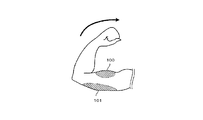
- the block diagram of the massage mechanism of the seat apparatus of FIG. The figure which shows the state which the arm part of a human body is bent.
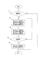
- 3 is a flowchart showing processing performed by a control unit of the sheet apparatus of FIG.
- the seat device 1 reduces a seat occupant's fatigue, a seat back 12 that supports the back of the seated person, a seat cushion 13 that supports a part of the buttocks and legs of the seated person. And a fatigue reduction device 11.
- the seat back 12 and the seat cushion 13 are configured by, for example, covering a cushion material made of soft urethane with a cover 15.
- the seat back 12 is supported by the seat cushion 13 in such a manner that it can be tilted with respect to the seat cushion 13.
- the seat cushion 13 is fixed to the floor surface of the passenger compartment.
- the fatigue reduction device 11 includes a massage mechanism 20 configured to massage a seated person, a vibration generating mechanism 30 configured to apply vibration to the seated person, the massage mechanism 20, and vibration. And a control unit 40 configured to operate the generating mechanism 30.
- the massage mechanism 20 includes two first massage mechanisms 201 for massaging the occupant's trapezius muscles and two second massage mechanisms 202 for massaging the occupant's latissimus dorsi muscles.
- Both the first massage mechanism 201 and the second massage mechanism 202 are provided on the left side and the right side of the seat back 12 so as to correspond to the right half and the left half of the seated person. That is, one set of the first massage mechanism 201 and the second massage mechanism 202 is provided on the left side and the right side of the seat back 12.
- the first massaging mechanism 201 and the second massaging mechanism 202 include an air bag 23 that expands as air flows in, a compressor 21 that supplies compressed air to the air bag 23, an air bag 23, and a compressor 21, a first flow path 25 that branches from the middle of the first flow path 25, a first valve 22 that switches a gas flow in the first flow path 25, and a second flow path And a second valve 24 for switching the gas flow at 26.
- the air bag 23 is provided corresponding to each of the first and second massage mechanisms 201 and 202.
- the components other than the air bag 23, that is, the compressor 21, the first flow path 25, the second flow path 26, the first valve 22 and the second valve 24 are composed of two first massage mechanisms 201 (or two second massage mechanisms). 202), and may be shared by the two first massage mechanisms 201 (or the two second massage mechanisms 202).
- the compressor 21 may be shared by all of the first and second massage mechanisms 201 and 202.
- the air bag 23 is formed of an elastic material.
- the air bag 23 is provided in contact with the cover 15.
- the air bag 23 expands when air is supplied and contracts when air is discharged.
- the air bag 23 pushes the cover 15 from the inside to the outside of the seat back 12.
- the first flow path 25 and the second flow path 26 may be formed of, for example, an elastic tube, or may be formed of a material that does not elastically deform such as metal.
- the second channel 26 has a first end connected to the first channel 25 and a second end opposite to the first end, and the second end is open to the atmosphere. ing.
- the first valve 22 and the second valve 24 are electromagnetic valves that are switched between a valve open state and a valve closed state by being electrically controlled.
- the first valve 22 is provided in the first flow path 25 between the branch portion where the second flow path 26 branches and the compressor 21.
- the first valve 22 allows the supply of air from the compressor 21 to the air bladder 23 in the opened state. Further, the first valve 22 restricts the supply of air from the compressor 21 to the air bladder 23 in the closed state.
- the second valve 24 permits the outflow of air from the air bag 23 to the atmosphere in the open state. Further, the second valve 24 restricts the outflow of air from the air bag 23 to the atmosphere in the closed state.
- the air supplied from the compressor 21 to the air bladder 23 is compressed, when the air bladder 23 is expanded, the inside of the air bladder 23 is at a higher pressure than the atmospheric pressure. Therefore, when the first valve 22 is closed and the second valve 24 is opened, the air in the air bladder 23 is discharged into the atmosphere through the second flow path 26. As a result, the air bag 23 contracts. Thus, the first and second massage mechanisms 201 and 202 do not press the seated person's back.
- the air bags 23 of the first and second massage mechanisms 201 and 202 alternately repeat expansion and contraction at a period of less than 1 Hz. Further, the air bladder 23 of the first and second massage mechanisms 201 and 202 presses the back of the seated person with a force of 15 to 20 kPa when inflated.
- the vibration generating mechanism 30 is configured to transmit vibrations to two first vibration generating mechanisms 301 configured to transmit vibration to the seated person's trapezius muscle and to the seated person's latissimus back muscle. And two second vibration generating mechanisms 302 configured as described above.
- each of the first and second vibration generating mechanisms 301 and 302 is attached to a corresponding one of the air bags 23 of the first and second massage mechanisms 201 and 202.
- the first and second vibration generating mechanisms 301 and 302 are preferably attached to a surface of the air bag 23 opposite to the surface facing the cover 15.
- the vibration generating mechanism 30 may be configured to generate vibration by driving a motor with a weight eccentric to the output shaft, for example, and periodically supplies a voltage to the piezoelectric element or solenoid. It may be configured to generate vibration.
- the vibration generating mechanism 30 is configured to be able to vibrate at a frequency (for example, a frequency of about 80 to 100 Hz) that causes muscle tension in the human muscle.
- the vibration generating mechanism 30 of this embodiment gives vibration to the seated person's back through the air bag 23 and the cover 15 by applying vibration to the air bag 23.
- the air bag 23 is preferably contracted so that the vibration is not attenuated.
- control unit 40 is electrically connected to the massage mechanism 20 (specifically, the compressor 21, the first valve 22 and the second valve 24) and the vibration generating mechanism 30. Or it is connected by the vehicle-mounted network represented by CAN (Control Area Network).
- CAN Control Area Network
- the control unit 40 is configured by a known microcomputer including a CPU, a RAM, a ROM, and the like.
- the control unit 40 controls the driving of the massage mechanism 20 and the vibration generating mechanism 30 by executing a program read from the ROM by the CPU.
- the control unit 40 starts controlling the massage mechanism 20 and the vibration generating mechanism 30 when a signal is input from an operation unit (manual operation unit) 41 including one or more switches connected to the control unit 40. do it.
- the trapezius muscle (first muscle) is an antagonistic muscle for the latissimus dorsi muscle (second muscle), and the latissimus back muscle (second muscle) is an antagonistic muscle for the trapezius muscle (first muscle).
- the seat device 1 includes a first massage mechanism 201 that massages the trapezius muscle, a second vibration generation mechanism 302 that applies vibrations that tension the antagonistic muscle (the latissimus dorsi muscle) to the trapezius muscle, and the latissimus dorsi muscle.
- a first vibration generating mechanism 301 that applies a vibration that tensions the antagonistic muscles (the latissimus dorsi muscles) for the latissimus dorsi.
- step S1 the control unit 40 determines whether or not a control start condition is satisfied.
- the control start condition is, for example, that a seated person operates a start switch provided in the operation unit 41, and more specifically, receives a signal transmitted by operating the start switch.
- step S1: YES the control unit 40 proceeds to step S2.
- step S1: NO the control unit 40 once ends this process.
- step S2 the control unit 40 operates both the first massage mechanism 201 and the second vibration generation mechanism 302, and stops the second massage mechanism 202 and the first vibration generation mechanism 301.
- the control unit 40 causes the first massage mechanism 201 to massage the occupant's trapezius muscle and causes the second vibration generation mechanism 302 to vibrate the seated person's latissimus dorsi muscle.
- the control unit 40 restricts driving of the second massaging mechanism 202 so as not to massage the seated person's latissimus dorsi muscle, and restricts driving of the first vibration generating mechanism 301 to prevent the Avoid vibration of the trapezius muscle.
- the control unit 40 switches the second valve 24 of the first massage mechanism 201 to a closed state, and switches the first valve 22 of the first massage mechanism 201 to a valve open state. Subsequently, the control unit 40 drives the compressor 21 of the first massage mechanism 201. Thus, compressed air is supplied to the air bladder 23 of the first massage mechanism 201, and the air bladder 23 is inflated. Then, the control unit 40 stops driving the compressor 21 of the first massage mechanism 201. Subsequently, the control unit 40 switches the second valve 24 of the first massage mechanism 201 to the valve open state. Thus, air is discharged from the air bag 23 of the first massage mechanism 201, and the air bag 23 contracts. Therefore, the control unit 40 causes the first massage mechanism 201 to massage the trapezius muscle of the seated person by inflating or contracting the air bladder 23 of the first massage mechanism 201 at a predetermined cycle.
- control unit 40 drives the second vibration generating mechanism 302. In this way, the control unit 40 causes the second vibration generating mechanism 302 to apply a vibration stimulus having a frequency that causes muscle tone to the seated dorsum muscle.
- the control unit 40 does not drive the second massage mechanism 202 and the first vibration generating mechanism 301. And when the elapsed time after starting the process of step S2 becomes more than determination time, the control part 40 will complete
- the “determination time” referred to here may be a predetermined fixed value or a variable value that can be changed by the seated person. When the determination time is set to a fixed value, for example, a time between several seconds to several tens of seconds may be used.
- Step S3 the control unit 40 operates both the second massage mechanism 202 and the first vibration generating mechanism 301 in a manner substantially similar to Step S2, and stops the first massage mechanism 201 and the second vibration generating mechanism 302. .
- the control unit 40 causes the second massage mechanism 202 to massage the seated latissimus dorsi muscle, and causes the first vibration generating mechanism 301 to vibrate the seated person's trapezius muscle.
- the control unit 40 restricts the driving of the first massage mechanism 201 so as not to massage the occupant's trapezius muscle, and restricts the driving of the second vibration generating mechanism 302 to allow the seated person to massage.
- the control unit 40 switches between a state where the first massage mechanism 201 and the second vibration generation mechanism 302 are operated and a state where the second massage mechanism 202 and the first vibration generation mechanism 301 are operated.
- step S4 the control unit 40 determines whether or not a control end condition is satisfied.
- the control end condition is, for example, that the seated person operates an end switch provided in the operation unit 41, and more specifically, receives a signal transmitted by operating the end switch.
- step S4: YES the control unit 40 proceeds to step S5.
- step S4: NO the control unit 40 shifts the process to step S2.
- step S4 in order to reduce the fatigue of the seated person, the control unit 40 performs the first massage mechanism 201, the second massage mechanism 202, the first vibration generation mechanism 301, and the second vibration generation mechanism. 302 is driven intermittently. In other words, the state in which the first massage mechanism 201 and the second vibration generating mechanism 302 are operated and the state in which the second massage mechanism 202 and the first vibration generating mechanism 301 are operated are alternately repeated.
- step S5 the control unit 40 stops driving the second massage mechanism 202 and the first vibration generating mechanism 301, and temporarily ends this process. Next, the operation of the sheet apparatus 1 will be described.
- the seat device 1 starts an operation for reducing the fatigue of the seated person by receiving a signal from the operation unit 41 operated by the seated person (driver). That is, the first massage mechanism 201 massages the occupant's trapezius muscle, and at the same time, the second vibration generating mechanism 302 transmits vibrations that cause muscle tension to the seated dorsum muscle.
- the trapezius muscle is massaged in a state where the muscle tone of the trapezius muscle, which is an antagonistic muscle for the latissimus dorsi muscle, is relaxed.
- the second massage mechanism 202 massages the seated dorsum muscle, and at the same time, the first vibration generating mechanism 301 transmits vibrations that cause muscle tension to the seated person's trapezius muscle.
- the latissimus dorsi muscle is massaged in a state where the muscle tone of the latissimus dorsi muscle, which is an antagonistic muscle for the trapezius muscle, is relaxed.
- the second vibration generating mechanism 302 imparts vibration stimulation at a frequency that causes muscle tension to the latissimus dorsi muscle, thereby causing muscle tension in the latissimus dorsi muscle and the muscle tone of the trapezius muscle, which is an antagonist muscle for the latissimus dorsi muscle.
- the 1st massage mechanism 201 can relieve the muscle tone of a trapezius muscle effectively by massaging the trapezius muscle in which the muscle tone was suppressed.
- the seat device 1 can improve the fatigue reduction effect of the seated person.
- the first vibration generating mechanism 301 applies a vibration stimulus having a frequency that causes muscle tension to the trapezius muscle, thereby causing muscle tension in the trapezius muscle and the muscle of the latissimus dorsi muscle that is an antagonist muscle for the trapezius muscle. Tension can be eased. Furthermore, the 2nd massage mechanism 202 can relieve the muscle tone of the latissimus dorsi muscle by massaging the latissimus dorsi muscle whose muscle tone was suppressed. In this way, not only the muscle tone of the trapezius muscle can be relieved, but also the muscle tone of the latissimus dorsi muscle can be relieved. For this reason, in order to relieve the muscle tone of the trapezius muscle, it can suppress that the muscle tone of the latissimus back muscle is promoted.
- the muscle corresponding to the position where the massage mechanism 20 and the vibration generating mechanism 30 are provided may not be the trapezius and latissimus dorsi.
- the seat cushion 13 may be extended downward, a part extending downward from the knee of the seated person may be provided, and the fatigue reduction device 11 may be provided at the part. According to this, the fatigue reduction effect of the muscle below the knee and its antagonist muscle can be improved.
- the control unit 40 may not be provided.
- the operation unit 41 may be electrically connected to the massage mechanism 20 and the vibration generation mechanism 30, and the massage mechanism 20 and the vibration generation mechanism 30 may be activated and stopped according to a signal from the operation unit 41.
- a switch that alternately switches between a state in which the first massage mechanism 201 and the second vibration generation mechanism 302 operate and a state in which the second massage mechanism 202 and the first vibration generation mechanism 301 operate is provided. May be.
- whether or not the control start condition is satisfied may not be determined based on the operation of the start switch provided in the operation unit 41. For example, it may be determined according to whether the travel distance of the vehicle has become a predetermined distance or more, or may be determined according to whether the driving time of the vehicle has become a predetermined time or more, The determination may be made based on the steering operation history.
- whether or not the control end condition is satisfied may not be determined based on the operation of the end switch provided in the operation unit 41. For example, what is necessary is just to determine based on the elapsed time after satisfy
- the vibration generating mechanism 30 may be arranged so as to contact the back of the seated person without using the massage mechanism 20.
- the second massage mechanism 202 and the first vibration generation mechanism 301 may not be included.
- the seat device 1 may not include the first massage mechanism 201 and the second vibration generation mechanism 302 as long as the sheet device 1 includes the second massage mechanism 202 and the first vibration generation mechanism 301.
- the control unit 40 does not need to be for vehicles. For example, it may be used for an aircraft seat or a household seat.
- the control part 40 is not restricted to what performs a software process about all the processes which self performs.
- the control unit 40 may include a dedicated hardware circuit (for example, an application specific integrated circuit: ASIC) that performs hardware processing for at least a part of processing executed by itself. That is, the control unit 40 includes 1) one or more processors that operate according to a computer program (software), 2) one or more dedicated hardware circuits that execute at least some of various processes, or 3) A combination thereof may be configured as a circuit.
- the processor includes a CPU and a memory such as a RAM and a ROM, and the memory stores program codes or instructions configured to cause the CPU to execute processing.
- Memory or computer readable media includes any available media that can be accessed by a general purpose or special purpose computer.
Landscapes
- Health & Medical Sciences (AREA)
- Engineering & Computer Science (AREA)
- Public Health (AREA)
- Veterinary Medicine (AREA)
- Rehabilitation Therapy (AREA)
- Life Sciences & Earth Sciences (AREA)
- Animal Behavior & Ethology (AREA)
- General Health & Medical Sciences (AREA)
- Pain & Pain Management (AREA)
- Physical Education & Sports Medicine (AREA)
- Epidemiology (AREA)
- Aviation & Aerospace Engineering (AREA)
- Transportation (AREA)
- Mechanical Engineering (AREA)
- Percussion Or Vibration Massage (AREA)
- Chair Legs, Seat Parts, And Backrests (AREA)
- Passenger Equipment (AREA)
- Seats For Vehicles (AREA)
Abstract
シート装置は、第1の筋をマッサージするように構成されたマッサージ機構と、前記第1の筋に対する拮抗筋である第2の筋に筋緊張を引き起こす周波数の振動刺激を付与するように構成された振動発生機構と、を備える。
Description
本発明は、着座者をマッサージする機能を有するシート装置に関する。
従来から、マッサージ機構を内蔵したシート装置が知られている。例えば、特許文献1には、シートの着座面全体を構成するパッドと、当該パッドに配置され、ガスの吸入及び排出によって着座者の背中を押圧するマッサージ機構と、当該マッサージ機構に振動を伝達する振動発生機構と、を備えるシート装置が開示されている。
上記のようなシート装置には、着座者の疲労低減効果を高める点について、改善の余地が残されている。
本発明の目的は、疲労低減効果を向上できるシート装置を提供することにある。
本発明の目的は、疲労低減効果を向上できるシート装置を提供することにある。
上記の課題を解決するシート装置は、第1の筋をマッサージするように構成されたマッサージ機構と、前記第1の筋に対する拮抗筋である第2の筋に、筋緊張を引き起こす周波数の振動刺激を付与するように構成された振動発生機構と、を備える。
以下、シート装置を車両の運転席に適用した一実施形態について、図面を参照しつつ説明する。
図1及び図2に示すように、シート装置1は、着座者の背中を支えるシートバック12と、着座者の臀部及び脚部の一部を支えるシートクッション13と、着座者の疲労を低減させるための疲労低減装置11と、を備える。
図1及び図2に示すように、シート装置1は、着座者の背中を支えるシートバック12と、着座者の臀部及び脚部の一部を支えるシートクッション13と、着座者の疲労を低減させるための疲労低減装置11と、を備える。
シートバック12及びシートクッション13は、例えば、軟質のウレタンからなるクッション材をカバー15で覆うことで構成される。シートバック12は、シートクッション13に対して傾動自在な態様で、シートクッション13に支持されている。シートクッション13は、車室の床面に固定されている。
図2に示すように、疲労低減装置11は、着座者をマッサージするように構成されたマッサージ機構20と、着座者に振動を与えるように構成された振動発生機構30と、マッサージ機構20及び振動発生機構30を作動させるように構成された制御部40と、を有する。
図1に示すように、マッサージ機構20は、着座者の僧帽筋をマッサージする2つの第1マッサージ機構201と、着座者の広背筋をマッサージする2つの第2マッサージ機構202と、を備える。第1マッサージ機構201及び第2マッサージ機構202はともに、着座者の右半身と左半身とに対応するように、シートバック12の左側と右側とに1つずつ設けられる。すなわち、第1マッサージ機構201と第2マッサージ機構202とのセットが、シートバック12の左側と右側とに1セットずつ設けられる。
図2に示すように、第1マッサージ機構201及び第2マッサージ機構202は、空気の流入に伴い膨張する空気袋23と、空気袋23に圧縮空気を供給するコンプレッサ21と、空気袋23とコンプレッサ21とを接続する第1流路25と、第1流路25の途中から分岐する第2流路26と、第1流路25における気体の流れを切り替える第1バルブ22と、第2流路26における気体の流れを切り替える第2バルブ24と、を有する。
空気袋23は第1及び第2マッサージ機構201,202の各々に対応して設けられる。空気袋23以外の構成要素、すなわちコンプレッサ21、第1流路25、第2流路26、第1バルブ22及び第2バルブ24は、2つの第1マッサージ機構201(或いは2つの第2マッサージ機構202)の各々に対応して設けられてもよいし、2つの第1マッサージ機構201(或いは2つの第2マッサージ機構202)で共有されてもよい。コンプレッサ21は、第1及び第2マッサージ機構201,202の全てで共有されてもよい。
空気袋23は、弾性を有する材料で形成される。空気袋23は、カバー15に接するように設けられる。そして、空気袋23は、空気が供給されたときに膨張し、空気が排出されるときに収縮する。空気袋23が膨張する場合、空気袋23は、シートバック12の内側から外側に向けてカバー15を押す。
第1流路25及び第2流路26は、例えば、弾性を有するチューブで構成してもよいし、金属など弾性変形しない材料で形成されてもよい。また、第2流路26は、第1流路25と接続される第1端部と、第1端部の反対側の第2端部とを有し、第2端部は大気に開放されている。
第1バルブ22及び第2バルブ24は、電気的に制御されることによって開弁状態と閉弁状態とに切り替わる電磁弁である。第1バルブ22は、第1流路25において、第2流路26が分岐する分岐部位と、コンプレッサ21との間に設けられる。第1バルブ22は、開弁状態において、コンプレッサ21から空気袋23への空気の供給を許容する。また、第1バルブ22は、閉弁状態において、コンプレッサ21から空気袋23への空気の供給を制限する。第2バルブ24は、開弁状態において、空気袋23内から大気中への空気の流出を許容する。また、第2バルブ24は、閉弁状態において、空気袋23内から大気中への空気の流出を制限する。
したがって、第1バルブ22を開弁状態にし、第2バルブ24を閉弁状態にした状態で、コンプレッサ21を駆動すると、コンプレッサ21から第1流路25を通して空気袋23に空気が供給される。その結果、空気袋23が着座者に向かって膨張する。こうして、第1及び第2マッサージ機構201,202は、着座者の背中(背面)を押圧する。
コンプレッサ21から空気袋23に供給される空気は圧縮されているため、空気袋23が膨張したとき、空気袋23内は、大気圧に比べて高圧になっている。したがって、第1バルブ22を閉弁状態にし、第2バルブ24を開弁状態にすると、空気袋23内の空気が第2流路26を通って大気中に排出される。その結果、空気袋23が収縮する。こうして、第1及び第2マッサージ機構201,202は、着座者の背中を押圧しなくなる。
なお、第1及び第2マッサージ機構201,202の空気袋23は、1Hz未満の周期で膨張と収縮とを交互に繰り返す。また、第1及び第2マッサージ機構201,202の空気袋23は、膨張しているときに、15~20kPaの力で着座者の背中を押圧する。
図1に示すように、振動発生機構30は、着座者の僧帽筋に振動を伝達するように構成された2つの第1振動発生機構301と、着座者の広背筋に振動を伝達するように構成された2つの第2振動発生機構302と、を備える。
図2に示すように、第1及び第2振動発生機構301,302の各々は、第1及び第2マッサージ機構201,202の空気袋23のうち対応する1つに取り付けられる。第1及び第2振動発生機構301,302は、空気袋23において、カバー15に対向する面とは反対側の面に取り付けることが好ましい。振動発生機構30は、例えば、出力軸に偏心させた錘を取り付けたモータを駆動することで振動を発生するように構成されてもよいし、圧電素子又はソレノイドに周期的に電圧を供給することで振動を発生するように構成されてもよい。また、振動発生機構30は、人体の筋肉に筋緊張を引き起こす周波数(例えば、80~100Hz程度の周波数)で振動可能に構成される。
そして、本実施形態の振動発生機構30は、空気袋23に振動を与えることで、空気袋23とカバー15とを介して着座者の背中に振動を与える。なお、振動発生機構30によって着座者の背中に振動を与える場合には、振動が減衰しないように、空気袋23を収縮させることが好ましい。
図2に示すように、制御部40は、マッサージ機構20(詳細には、コンプレッサ21、第1バルブ22及び第2バルブ24)及び振動発生機構30に対して、電気的に接続されているか、または、CAN(Control Area Network)に代表される車載ネットワークによって接続されている。
制御部40は、CPU、RAM及びROM等からなる周知のマイクロコンピュータで構成される。制御部40は、ROMから読み出したプログラムをCPUで実行することによって、マッサージ機構20及び振動発生機構30の駆動を制御する。なお、制御部40は、制御部40に接続された1つ以上のスイッチを含む操作部(手動操作部)41から信号が入力されたときに、マッサージ機構20及び振動発生機構30の制御を開始すればよい。
次に、図3を参照して、筋肉間の拮抗作用について説明する。
図3に示すように、肘関節を屈曲する場合、上腕二頭筋100が緊張(収縮)し、上腕三頭筋101の緊張が緩和される。一方、肘関節を伸展する場合、上腕二頭筋100の緊張が緩和され、上腕三頭筋101が緊張する。以降の説明では、肘関節における上腕二頭筋100と上腕三頭筋101のように、ある動作をするときに互いに逆の動きをする一対の筋について、一方の筋を、他方の筋に対する拮抗筋と表現する。
図3に示すように、肘関節を屈曲する場合、上腕二頭筋100が緊張(収縮)し、上腕三頭筋101の緊張が緩和される。一方、肘関節を伸展する場合、上腕二頭筋100の緊張が緩和され、上腕三頭筋101が緊張する。以降の説明では、肘関節における上腕二頭筋100と上腕三頭筋101のように、ある動作をするときに互いに逆の動きをする一対の筋について、一方の筋を、他方の筋に対する拮抗筋と表現する。
本実施形態では、僧帽筋(第1の筋)は広背筋(第2の筋)に対する拮抗筋であり、広背筋(第2の筋)は僧帽筋(第1の筋)に対する拮抗筋である。したがって、本実施形態のシート装置1は、僧帽筋をマッサージする第1マッサージ機構201と、僧帽筋に対する拮抗筋(広背筋)を緊張させる振動を与える第2振動発生機構302と、広背筋をマッサージする第2マッサージ機構202と、広背筋に対する拮抗筋(広背筋)を緊張させる振動を与える第1振動発生機構301と、を備える。
次に、図4に示すフローチャートを参照して、制御部40が行う処理について説明する。
ステップS1では、制御部40は、制御開始条件が満たされたか否かを判定する。制御開始条件は、例えば、着座者が操作部41に設けられた開始スイッチを操作すること、より詳細には、開始スイッチを操作することにより送信された信号を受信することである。制御開始条件が満たされた場合(ステップS1:YES)、制御部40は、ステップS2へ進む。一方、制御開始条件が満たされなかった場合(ステップS1:NO)、制御部40は、本処理を一旦終了する。
ステップS1では、制御部40は、制御開始条件が満たされたか否かを判定する。制御開始条件は、例えば、着座者が操作部41に設けられた開始スイッチを操作すること、より詳細には、開始スイッチを操作することにより送信された信号を受信することである。制御開始条件が満たされた場合(ステップS1:YES)、制御部40は、ステップS2へ進む。一方、制御開始条件が満たされなかった場合(ステップS1:NO)、制御部40は、本処理を一旦終了する。
ステップS2では、制御部40は、第1マッサージ機構201及び第2振動発生機構302を共に作動させ、第2マッサージ機構202及び第1振動発生機構301を停止させる。具体的には、ステップS2において、制御部40は、第1マッサージ機構201に着座者の僧帽筋をマッサージさせ、第2振動発生機構302に着座者の広背筋に振動を与えさせる。また、ステップS2において、制御部40は、第2マッサージ機構202の駆動を制限して着座者の広背筋をマッサージさせないようにするとともに、第1振動発生機構301の駆動を制限して着座者の僧帽筋に振動を与えないようにする。
すなわち、制御部40は、第1マッサージ機構201の第2バルブ24を閉弁状態に切り替え、第1マッサージ機構201の第1バルブ22を開弁状態に切り替える。続いて、制御部40は、第1マッサージ機構201のコンプレッサ21を駆動させる。こうして、第1マッサージ機構201の空気袋23に圧縮空気が供給され、空気袋23が膨張する。そして、制御部40は、第1マッサージ機構201のコンプレッサ21の駆動を停止させる。続いて、制御部40は、第1マッサージ機構201の第2バルブ24を開弁状態に切り替える。こうして、第1マッサージ機構201の空気袋23内から空気が排出され、空気袋23が収縮する。したがって、制御部40は、所定の周期で第1マッサージ機構201の空気袋23を膨張させたり収縮させたりすることで、第1マッサージ機構201に着座者の僧帽筋をマッサージさせる。
また、制御部40は、第2振動発生機構302を駆動させる。こうして、制御部40は、第2振動発生機構302に筋緊張を引き起こす周波数の振動刺激を着座者の広背筋に付与させる。
その一方で、制御部40は、第2マッサージ機構202及び第1振動発生機構301を駆動させない。
そして、制御部40は、ステップS2の処理を開始してからの経過時間が判定時間以上となると、ステップS2の処理を終了し、次のステップS3の処理を開始する。なお、ここで言う「判定時間」は、予め定められた固定値であってもよいし、着座者が変更できる可変値であってもよい。判定時間を固定値とする場合には、例えば、数秒~数十秒の間の時間とすればよい。
そして、制御部40は、ステップS2の処理を開始してからの経過時間が判定時間以上となると、ステップS2の処理を終了し、次のステップS3の処理を開始する。なお、ここで言う「判定時間」は、予め定められた固定値であってもよいし、着座者が変更できる可変値であってもよい。判定時間を固定値とする場合には、例えば、数秒~数十秒の間の時間とすればよい。
ステップS3では、制御部40は、ステップS2と略同様の態様で、第2マッサージ機構202及び第1振動発生機構301を共に作動させ、第1マッサージ機構201及び第2振動発生機構302を停止させる。具体的には、ステップS3において、制御部40は、第2マッサージ機構202に着座者の広背筋をマッサージさせ、第1振動発生機構301に着座者の僧帽筋に振動を与えさせる。また、ステップS3において、制御部40は、第1マッサージ機構201の駆動を制限して着座者の僧帽筋をマッサージさせないようにするとともに、第2振動発生機構302の駆動を制限して着座者の広背筋に振動を与えないようにする。すなわち、制御部40は、第1マッサージ機構201及び第2振動発生機構302が作動する状態と、第2マッサージ機構202及び第1振動発生機構301が作動する状態と、を切り替える。
そして、制御部40は、ステップS3の処理を開始してからの経過時間が判定時間以上となると、ステップS3の処理を終了し、次のステップS4の処理を開始する。
ステップS4では、制御部40は、制御終了条件が満たされたか否かを判定する。制御終了条件は、例えば、着座者が操作部41に設けられた終了スイッチを操作すること、より詳細には終了スイッチを操作することにより送信された信号を受信することである。制御終了条件が満たされた場合(ステップS4:YES)、制御部40は、ステップS5へ進む。一方、制御終了条件が満たされなかった場合(ステップS4:NO)、制御部40は、ステップS2にその処理を移行する。すなわち、この場合(ステップS4:NO)、着座者の疲労を軽減するために、制御部40は、第1マッサージ機構201、第2マッサージ機構202、第1振動発生機構301及び第2振動発生機構302を断続的に駆動する。言い換えれば、第1マッサージ機構201及び第2振動発生機構302が作動する状態と、第2マッサージ機構202及び第1振動発生機構301が作動する状態とが交互に繰り返される。
ステップS4では、制御部40は、制御終了条件が満たされたか否かを判定する。制御終了条件は、例えば、着座者が操作部41に設けられた終了スイッチを操作すること、より詳細には終了スイッチを操作することにより送信された信号を受信することである。制御終了条件が満たされた場合(ステップS4:YES)、制御部40は、ステップS5へ進む。一方、制御終了条件が満たされなかった場合(ステップS4:NO)、制御部40は、ステップS2にその処理を移行する。すなわち、この場合(ステップS4:NO)、着座者の疲労を軽減するために、制御部40は、第1マッサージ機構201、第2マッサージ機構202、第1振動発生機構301及び第2振動発生機構302を断続的に駆動する。言い換えれば、第1マッサージ機構201及び第2振動発生機構302が作動する状態と、第2マッサージ機構202及び第1振動発生機構301が作動する状態とが交互に繰り返される。
ステップS5では、制御部40は、第2マッサージ機構202及び第1振動発生機構301の駆動を停止し、本処理を一旦終了する。
次に、シート装置1の作用について説明する。
次に、シート装置1の作用について説明する。
シート装置1は、着座者(運転者)が操作する操作部41からの信号を受け付けることで、着座者の疲労低減のための動作を開始する。すなわち、第1マッサージ機構201が着座者の僧帽筋をマッサージし、それと同時に、第2振動発生機構302が筋緊張を引き起こす振動を着座者の広背筋に伝達する。こうして、広背筋に対する拮抗筋である僧帽筋の筋緊張が緩和された状態で、僧帽筋がマッサージされる。そして、判定時間が経過すると、第2マッサージ機構202が着座者の広背筋をマッサージし、それと同時に、第1振動発生機構301が筋緊張を引き起こす振動を着座者の僧帽筋に伝達する。こうして、僧帽筋に対する拮抗筋である広背筋の筋緊張が緩和された状態で、広背筋がマッサージされる。
上述した実施形態によれば、以下に示す効果を得ることができる。
(1)第2振動発生機構302が広背筋に筋緊張を引き起こす周波数の振動刺激を付与することで、広背筋に筋緊張を起こすとともに、広背筋に対する拮抗筋である僧帽筋の筋緊張を緩和できる。さらに、第1マッサージ機構201が、筋緊張が抑制された僧帽筋をマッサージすることで、僧帽筋の筋緊張を効果的に緩和できる。こうして、シート装置1は、着座者の疲労低減効果を向上できる。
(1)第2振動発生機構302が広背筋に筋緊張を引き起こす周波数の振動刺激を付与することで、広背筋に筋緊張を起こすとともに、広背筋に対する拮抗筋である僧帽筋の筋緊張を緩和できる。さらに、第1マッサージ機構201が、筋緊張が抑制された僧帽筋をマッサージすることで、僧帽筋の筋緊張を効果的に緩和できる。こうして、シート装置1は、着座者の疲労低減効果を向上できる。
(2)第1振動発生機構301が僧帽筋に筋緊張を引き起こす周波数の振動刺激を付与することで、僧帽筋に筋緊張を起こすとともに、僧帽筋に対する拮抗筋である広背筋の筋緊張を緩和できる。さらに、第2マッサージ機構202が、筋緊張が抑制された広背筋をマッサージすることで、広背筋の筋緊張を効果的に緩和できる。こうして、僧帽筋の筋緊張を緩和するだけでなく、広背筋の筋緊張を緩和することができる。このため、僧帽筋の筋緊張を緩和するために、広背筋の筋緊張が亢進されることを抑制できる。
(3)制御部40が、第1マッサージ機構201及び第2振動発生機構302を作動させる状態と、第2マッサージ機構202及び第1振動発生機構301を作動させる状態と、を自動的に交互に切り替える。このため、僧帽筋及び広背筋の双方の筋の筋緊張を効率的に緩和できる。
(4)車両を運転する運転者は、ステアリング操作を行うことにより、僧帽筋及び広背筋が筋緊張しやすい。そこで、シート装置1を車両の運転席に適用することで、運転者の疲労低減効果を得ることができる。
以下に、上述した実施形態の別の実施形態を説明する。
・マッサージ機構20及び振動発生機構30が設けられる位置に対応する筋は、僧帽筋及び広背筋でなくてもよい。例えば、シートクッション13を下方に延長し、着座者の膝から下に沿う部位を設け、当該部位に疲労低減装置11を設けてもよい。これによれば、膝から下の部位の筋肉と、その拮抗筋の疲労低減効果を向上できる。
・マッサージ機構20及び振動発生機構30が設けられる位置に対応する筋は、僧帽筋及び広背筋でなくてもよい。例えば、シートクッション13を下方に延長し、着座者の膝から下に沿う部位を設け、当該部位に疲労低減装置11を設けてもよい。これによれば、膝から下の部位の筋肉と、その拮抗筋の疲労低減効果を向上できる。
・制御部40が設けられていなくてもよい。例えば、操作部41がマッサージ機構20及び振動発生機構30に電気的に接続されており、操作部41からの信号に応じてマッサージ機構20及び振動発生機構30が作動及び停止してもよい。この場合、第1マッサージ機構201及び第2振動発生機構302が作動する状態と、第2マッサージ機構202及び第1振動発生機構301が作動する状態と、を交互に切り替えるスイッチ(手動スイッチ)が設けられてもよい。
・図4に示すフローチャートにおいて、制御開始条件が満たされたか否かは、操作部41に設けられた開始スイッチの操作に基づいて判定しなくてもよい。例えば、車両の走行距離が所定の距離以上になったか否かに応じて判定してもよいし、車両の運転時間が所定の時間以上になったか否かに応じて判定してもよいし、ステアリングの操作履歴に基づいて判定してもよい。
・図4に示すフローチャートにおいて、制御終了条件が満たされたか否かは、操作部41に設けられた終了スイッチの操作に基づいて判定しなくてもよい。例えば、制御開始条件を満たしてからの経過時間に基づいて判定すればよい。
・振動発生機構30は、マッサージ機構20を介さずに着座者の背中に当接するように配置されてもよい。この場合には、シート装置1は、第1マッサージ機構201及び第2振動発生機構302を備えていれば、第2マッサージ機構202及び第1振動発生機構301を備えなくてもよい。もしくは、シート装置1は、第2マッサージ機構202及び第1振動発生機構301を備えていれば、第1マッサージ機構201及び第2振動発生機構302を備えなくてもよい。
・シート装置1は車両用でなくてもよい。例えば、航空機のシートに用いられてもよいし、家庭用のシートに用いられてもよい。
・制御部40は、自身が実行する全ての処理についてソフトウェア処理を行うものに限られない。たとえば、制御部40は、自身が実行する処理の少なくとも一部についてハードウェア処理を行う専用のハードウェア回路(たとえば特定用途向け集積回路:ASIC)を備えてもよい。すなわち、制御部40は、1)コンピュータプログラム(ソフトウェア)に従って動作する1つ以上のプロセッサ、2)各種処理のうち少なくとも一部の処理を実行する1つ以上の専用のハードウェア回路、或いは3)それらの組み合わせ、を含む回路(circuitry)として構成し得る。プロセッサは、CPU並びに、RAM及びROM等のメモリを含み、メモリは、処理をCPUに実行させるように構成されたプログラムコードまたは指令を格納している。メモリすなわちコンピュータ可読媒体は、汎用または専用のコンピュータでアクセスできるあらゆる利用可能な媒体を含む。
・制御部40は、自身が実行する全ての処理についてソフトウェア処理を行うものに限られない。たとえば、制御部40は、自身が実行する処理の少なくとも一部についてハードウェア処理を行う専用のハードウェア回路(たとえば特定用途向け集積回路:ASIC)を備えてもよい。すなわち、制御部40は、1)コンピュータプログラム(ソフトウェア)に従って動作する1つ以上のプロセッサ、2)各種処理のうち少なくとも一部の処理を実行する1つ以上の専用のハードウェア回路、或いは3)それらの組み合わせ、を含む回路(circuitry)として構成し得る。プロセッサは、CPU並びに、RAM及びROM等のメモリを含み、メモリは、処理をCPUに実行させるように構成されたプログラムコードまたは指令を格納している。メモリすなわちコンピュータ可読媒体は、汎用または専用のコンピュータでアクセスできるあらゆる利用可能な媒体を含む。
Claims (5)
- 第1の筋をマッサージするように構成されたマッサージ機構と、
前記第1の筋に対する拮抗筋である第2の筋に筋緊張を引き起こす周波数の振動刺激を付与するように構成された振動発生機構と、を備える
シート装置。 - 前記マッサージ機構は第1マッサージ機構であり、前記振動発生機構は第2振動発生機構であり、
前記第1の筋に筋緊張を引き起こす周波数の振動刺激を付与するように構成された第1振動発生機構と、
前記第2の筋をマッサージするように構成された第2マッサージ機構と、をさらに備える
請求項1に記載のシート装置。 - 前記第1マッサージ機構及び前記第2振動発生機構が共に作動する状態と、前記第2マッサージ機構及び前記第1振動発生機構が共に作動する状態と、を切り替えるように構成された制御部をさらに備える
請求項2に記載のシート装置。 - 前記第1マッサージ機構及び前記第2振動発生機構が共に作動する状態と、前記第2マッサージ機構及び前記第1振動発生機構が共に作動する状態と、を切り替えるように構成された手動操作部をさらに備える
請求項2に記載のシート装置。 - 前記第1の筋及び前記第2の筋のうち、一方が僧帽筋であり、他方が広背筋である
請求項1乃至4の何れか一項に記載のシート装置。
Priority Applications (2)
| Application Number | Priority Date | Filing Date | Title |
|---|---|---|---|
| JP2019505858A JP7070545B2 (ja) | 2017-03-13 | 2018-02-28 | シート装置 |
| US16/492,799 US11896549B2 (en) | 2017-03-13 | 2018-02-28 | Seat device |
Applications Claiming Priority (2)
| Application Number | Priority Date | Filing Date | Title |
|---|---|---|---|
| JP2017047154 | 2017-03-13 | ||
| JP2017-047154 | 2017-03-13 |
Publications (1)
| Publication Number | Publication Date |
|---|---|
| WO2018168463A1 true WO2018168463A1 (ja) | 2018-09-20 |
Family
ID=63523293
Family Applications (1)
| Application Number | Title | Priority Date | Filing Date |
|---|---|---|---|
| PCT/JP2018/007470 Ceased WO2018168463A1 (ja) | 2017-03-13 | 2018-02-28 | シート装置 |
Country Status (3)
| Country | Link |
|---|---|
| US (1) | US11896549B2 (ja) |
| JP (1) | JP7070545B2 (ja) |
| WO (1) | WO2018168463A1 (ja) |
Cited By (3)
| Publication number | Priority date | Publication date | Assignee | Title |
|---|---|---|---|---|
| JP2020066354A (ja) * | 2018-10-25 | 2020-04-30 | トヨタ自動車株式会社 | 倒立型移動体 |
| GB2622696A (en) * | 2022-08-31 | 2024-03-27 | Rockwell Collins Inc | High comfort endurance haptic cushion |
| JP2024053103A (ja) * | 2020-08-31 | 2024-04-12 | テイ・エス テック株式会社 | 乗物用シート |
Families Citing this family (5)
| Publication number | Priority date | Publication date | Assignee | Title |
|---|---|---|---|---|
| US10874822B2 (en) * | 2018-11-21 | 2020-12-29 | Gulfstream Aerospace Corporation | Aircraft seat assembly including a vibration producing apparatus and method for fabricating the same |
| KR102359742B1 (ko) * | 2020-05-15 | 2022-02-08 | 박재범 | 다채널 사운드 시스템이 구비된 의자 |
| CN111529343B (zh) * | 2020-06-03 | 2021-10-26 | 复旦大学附属儿科医院 | 一种便于翻转的多体位全身包裹式空气波按摩装置 |
| US11357332B2 (en) * | 2020-08-11 | 2022-06-14 | Samuelson Group Inc. | Furniture with integrated acoustical system |
| FR3121883B1 (fr) * | 2021-04-19 | 2024-08-30 | Faurecia Sieges Dautomobile | Siège de véhicule |
Citations (3)
| Publication number | Priority date | Publication date | Assignee | Title |
|---|---|---|---|---|
| JP2000262578A (ja) * | 1999-03-12 | 2000-09-26 | Tadahiro Okura | 椅子形マッサージ機 |
| JP2013085571A (ja) * | 2011-10-13 | 2013-05-13 | Fuji Iryoki:Kk | マッサージ機 |
| DE102015217044A1 (de) * | 2015-09-07 | 2017-03-09 | Ford Global Technologies, Llc | Fahrzeugsitz mit Massagefunktion |
Family Cites Families (8)
| Publication number | Priority date | Publication date | Assignee | Title |
|---|---|---|---|---|
| US6212719B1 (en) * | 1997-10-10 | 2001-04-10 | D2Rm Corp. | Air massager cushioning device |
| US6087942A (en) * | 1998-05-18 | 2000-07-11 | Jb Research, Inc. | Tactile alert and massaging system |
| US20030028132A1 (en) * | 2001-07-03 | 2003-02-06 | Conair Corporation | Massage pad with selectively placeable massage actuators |
| US7727171B2 (en) | 2005-01-19 | 2010-06-01 | Toyota Boshoku Kabushiki Kaisha | Vehicle seats with plurality of pneumatic massaging elements |
| JP4628800B2 (ja) | 2005-01-19 | 2011-02-09 | トヨタ紡織株式会社 | 車両用シート |
| DE102006018184A1 (de) * | 2006-04-19 | 2007-10-25 | Bayerische Motoren Werke Ag | Sitz |
| EP2396193B1 (de) * | 2009-02-11 | 2015-04-08 | Daimler AG | Fahrzeugsitz mit einem polster eines sitzkissens und/oder einer sitzlehne und mit einer massageeinrichtung |
| JP5570776B2 (ja) | 2009-09-24 | 2014-08-13 | トヨタ紡織株式会社 | 車両用シート |
-
2018
- 2018-02-28 WO PCT/JP2018/007470 patent/WO2018168463A1/ja not_active Ceased
- 2018-02-28 JP JP2019505858A patent/JP7070545B2/ja active Active
- 2018-02-28 US US16/492,799 patent/US11896549B2/en active Active
Patent Citations (3)
| Publication number | Priority date | Publication date | Assignee | Title |
|---|---|---|---|---|
| JP2000262578A (ja) * | 1999-03-12 | 2000-09-26 | Tadahiro Okura | 椅子形マッサージ機 |
| JP2013085571A (ja) * | 2011-10-13 | 2013-05-13 | Fuji Iryoki:Kk | マッサージ機 |
| DE102015217044A1 (de) * | 2015-09-07 | 2017-03-09 | Ford Global Technologies, Llc | Fahrzeugsitz mit Massagefunktion |
Cited By (6)
| Publication number | Priority date | Publication date | Assignee | Title |
|---|---|---|---|---|
| JP2020066354A (ja) * | 2018-10-25 | 2020-04-30 | トヨタ自動車株式会社 | 倒立型移動体 |
| JP7121907B2 (ja) | 2018-10-25 | 2022-08-19 | トヨタ自動車株式会社 | 倒立型移動体 |
| JP2024053103A (ja) * | 2020-08-31 | 2024-04-12 | テイ・エス テック株式会社 | 乗物用シート |
| JP7733330B2 (ja) | 2020-08-31 | 2025-09-03 | テイ・エス テック株式会社 | 乗物用シート |
| GB2622696A (en) * | 2022-08-31 | 2024-03-27 | Rockwell Collins Inc | High comfort endurance haptic cushion |
| US12208903B2 (en) | 2022-08-31 | 2025-01-28 | Rockwell Collins, Inc. | High comfort endurance haptic cushion |
Also Published As
| Publication number | Publication date |
|---|---|
| US20200054518A1 (en) | 2020-02-20 |
| JPWO2018168463A1 (ja) | 2020-01-23 |
| JP7070545B2 (ja) | 2022-05-18 |
| US11896549B2 (en) | 2024-02-13 |
Similar Documents
| Publication | Publication Date | Title |
|---|---|---|
| JP7070545B2 (ja) | シート装置 | |
| KR102740913B1 (ko) | 에어 마사지 장치 | |
| JP2018100054A (ja) | 空気供給装置及び車両用シート | |
| CN215536408U (zh) | 具有会阴部按摩功能的按摩器 | |
| CN115701966B (zh) | 具有会阴部按摩功能的按摩器及其控制方法 | |
| WO2007094492A1 (ja) | 疲労軽減機能付自動車用シート | |
| CN105636569A (zh) | 伸展用垫 | |
| KR20220108282A (ko) | 회음부 마사지 기능을 갖는 마사지기 및 그 제어 방법 | |
| WO2016027437A1 (ja) | マッサージ装置 | |
| JP5890725B2 (ja) | 着座式マッサージ装置 | |
| JP3548052B2 (ja) | マッサージ機 | |
| JP4802633B2 (ja) | マッサージ機 | |
| JP6670604B2 (ja) | マッサージ機 | |
| KR200427267Y1 (ko) | 지압 돌기와 에어백을 구비한 안마의자 | |
| JP3903077B2 (ja) | マッサージ機 | |
| JP4194824B2 (ja) | マッサージ機 | |
| JP3913207B2 (ja) | マッサージ機 | |
| JP2001029416A (ja) | 椅子式マッサージ機 | |
| JP2001252315A (ja) | エアーマッサージ装置 | |
| JP3257752B2 (ja) | 椅子式エアーマッサージ機 | |
| JP6387033B2 (ja) | マッサージ機 | |
| JP4018462B2 (ja) | マッサージ機 | |
| JP5896864B2 (ja) | マッサージ機 | |
| JP2003339807A (ja) | 手揉機能付施療機 | |
| JP2009183550A (ja) | 足部マッサージ装置 |
Legal Events
| Date | Code | Title | Description |
|---|---|---|---|
| 121 | Ep: the epo has been informed by wipo that ep was designated in this application |
Ref document number: 18767496 Country of ref document: EP Kind code of ref document: A1 |
|
| ENP | Entry into the national phase |
Ref document number: 2019505858 Country of ref document: JP Kind code of ref document: A |
|
| NENP | Non-entry into the national phase |
Ref country code: DE |
|
| 122 | Ep: pct application non-entry in european phase |
Ref document number: 18767496 Country of ref document: EP Kind code of ref document: A1 |