WO2018168284A1 - 光学フィルム - Google Patents
光学フィルム Download PDFInfo
- Publication number
- WO2018168284A1 WO2018168284A1 PCT/JP2018/004664 JP2018004664W WO2018168284A1 WO 2018168284 A1 WO2018168284 A1 WO 2018168284A1 JP 2018004664 W JP2018004664 W JP 2018004664W WO 2018168284 A1 WO2018168284 A1 WO 2018168284A1
- Authority
- WO
- WIPO (PCT)
- Prior art keywords
- meth
- hard coat
- coat layer
- optical film
- layer
- Prior art date
- Legal status (The legal status is an assumption and is not a legal conclusion. Google has not performed a legal analysis and makes no representation as to the accuracy of the status listed.)
- Ceased
Links
Images

Classifications
-
- B—PERFORMING OPERATIONS; TRANSPORTING
- B32—LAYERED PRODUCTS
- B32B—LAYERED PRODUCTS, i.e. PRODUCTS BUILT-UP OF STRATA OF FLAT OR NON-FLAT, e.g. CELLULAR OR HONEYCOMB, FORM
- B32B27/00—Layered products comprising a layer of synthetic resin
- B32B27/18—Layered products comprising a layer of synthetic resin characterised by the use of special additives
-
- B—PERFORMING OPERATIONS; TRANSPORTING
- B32—LAYERED PRODUCTS
- B32B—LAYERED PRODUCTS, i.e. PRODUCTS BUILT-UP OF STRATA OF FLAT OR NON-FLAT, e.g. CELLULAR OR HONEYCOMB, FORM
- B32B27/00—Layered products comprising a layer of synthetic resin
- B32B27/30—Layered products comprising a layer of synthetic resin comprising vinyl (co)polymers; comprising acrylic (co)polymers
-
- C—CHEMISTRY; METALLURGY
- C09—DYES; PAINTS; POLISHES; NATURAL RESINS; ADHESIVES; COMPOSITIONS NOT OTHERWISE PROVIDED FOR; APPLICATIONS OF MATERIALS NOT OTHERWISE PROVIDED FOR
- C09D—COATING COMPOSITIONS, e.g. PAINTS, VARNISHES OR LACQUERS; FILLING PASTES; CHEMICAL PAINT OR INK REMOVERS; INKS; CORRECTING FLUIDS; WOODSTAINS; PASTES OR SOLIDS FOR COLOURING OR PRINTING; USE OF MATERIALS THEREFOR
- C09D5/00—Coating compositions, e.g. paints, varnishes or lacquers, characterised by their physical nature or the effects produced; Filling pastes
-
- C—CHEMISTRY; METALLURGY
- C09—DYES; PAINTS; POLISHES; NATURAL RESINS; ADHESIVES; COMPOSITIONS NOT OTHERWISE PROVIDED FOR; APPLICATIONS OF MATERIALS NOT OTHERWISE PROVIDED FOR
- C09D—COATING COMPOSITIONS, e.g. PAINTS, VARNISHES OR LACQUERS; FILLING PASTES; CHEMICAL PAINT OR INK REMOVERS; INKS; CORRECTING FLUIDS; WOODSTAINS; PASTES OR SOLIDS FOR COLOURING OR PRINTING; USE OF MATERIALS THEREFOR
- C09D5/00—Coating compositions, e.g. paints, varnishes or lacquers, characterised by their physical nature or the effects produced; Filling pastes
- C09D5/32—Radiation-absorbing paints
-
- C—CHEMISTRY; METALLURGY
- C09—DYES; PAINTS; POLISHES; NATURAL RESINS; ADHESIVES; COMPOSITIONS NOT OTHERWISE PROVIDED FOR; APPLICATIONS OF MATERIALS NOT OTHERWISE PROVIDED FOR
- C09D—COATING COMPOSITIONS, e.g. PAINTS, VARNISHES OR LACQUERS; FILLING PASTES; CHEMICAL PAINT OR INK REMOVERS; INKS; CORRECTING FLUIDS; WOODSTAINS; PASTES OR SOLIDS FOR COLOURING OR PRINTING; USE OF MATERIALS THEREFOR
- C09D7/00—Features of coating compositions, not provided for in group C09D5/00; Processes for incorporating ingredients in coating compositions
- C09D7/40—Additives
-
- C—CHEMISTRY; METALLURGY
- C09—DYES; PAINTS; POLISHES; NATURAL RESINS; ADHESIVES; COMPOSITIONS NOT OTHERWISE PROVIDED FOR; APPLICATIONS OF MATERIALS NOT OTHERWISE PROVIDED FOR
- C09J—ADHESIVES; NON-MECHANICAL ASPECTS OF ADHESIVE PROCESSES IN GENERAL; ADHESIVE PROCESSES NOT PROVIDED FOR ELSEWHERE; USE OF MATERIALS AS ADHESIVES
- C09J201/00—Adhesives based on unspecified macromolecular compounds
-
- C—CHEMISTRY; METALLURGY
- C09—DYES; PAINTS; POLISHES; NATURAL RESINS; ADHESIVES; COMPOSITIONS NOT OTHERWISE PROVIDED FOR; APPLICATIONS OF MATERIALS NOT OTHERWISE PROVIDED FOR
- C09J—ADHESIVES; NON-MECHANICAL ASPECTS OF ADHESIVE PROCESSES IN GENERAL; ADHESIVE PROCESSES NOT PROVIDED FOR ELSEWHERE; USE OF MATERIALS AS ADHESIVES
- C09J7/00—Adhesives in the form of films or foils
- C09J7/20—Adhesives in the form of films or foils characterised by their carriers
-
- B—PERFORMING OPERATIONS; TRANSPORTING
- B60—VEHICLES IN GENERAL
- B60J—WINDOWS, WINDSCREENS, NON-FIXED ROOFS, DOORS, OR SIMILAR DEVICES FOR VEHICLES; REMOVABLE EXTERNAL PROTECTIVE COVERINGS SPECIALLY ADAPTED FOR VEHICLES
- B60J1/00—Windows; Windscreens; Accessories therefor
Definitions
- the present invention relates to an optical film used for cars, mobile phones, home appliances, and the like.
- thermoforming is the most time-consuming part of window film construction. If there is a thermoforming defect, it will affect the quality (film floating, peeling, film breakage, visibility) when affixed to a car window. Therefore, thermoformability is one of the major problems in window films.
- the polyester film is mainly used for the window film base film from the viewpoint of quality and cost. It is known that the ratio of polyester film to the total film thickness of window film is 50% or more, and the thermal shrinkage of polyester film is reflected in the thermal shrinkage of window film and greatly contributes to the thermoformability of window film. It was.
- Patent Document 1 discloses a laminated film for window pasting in which at least one of the horizontal and vertical heat shrinkage rates of the base film is specified to a predetermined value.
- Patent Document 2 discloses a bifunctional (meth) acrylate compound having at least one of an alicyclic ring, an aromatic ring, and a heterocyclic structure in the molecule, and 3
- An optical film having a hard coat layer formed from a composition containing a polyfunctional acrylate compound having one or more (meth) acryloyl groups and a photopolymerization initiator on a transparent support is disclosed.
- high surface hardness is implement
- thermoformability and scratch resistance are in a trade-off relationship, and it is difficult to achieve high scratch resistance in optical films having excellent thermoformability. there were.
- in-vehicle wind films require more scratch resistance because they have more human contact than optical films for display devices.
- an object of the present invention is to provide an optical film having excellent thermoformability and scratch resistance.
- An optical film characterized by comprising: (A) Polyfunctional (meth) acrylate compound having 3 or more (meth) acryloyl groups (b) Bifunctional (meth) having 2 (meth) acryloyl groups and having an alicyclic structure in the molecule Acrylate compound (c) Bifunctional silicone (meth) acrylate compound (d) photopolymerization initiator having two (meth) acryloyl groups
- an optical film having excellent thermoformability and scratch resistance can be provided.
- (meth) acrylate is a general term for acrylate and methacrylate.
- the “(meth) acryloyl group” is a general term for an acryloyl group and a methacryloyl group.
- X to Y indicating a range means “X or more and Y or less”. Unless otherwise specified, measurement of operation and physical properties is performed under conditions of room temperature (20 to 25 ° C.) / Relative humidity 40 to 50%.
- the optical film 1 has a base layer 2 and a hard coat layer 3 disposed on one surface of the base layer 2, and the hard coat layer 3 includes the following (a) to (d): Preferably, it consists of the hardened
- A a polyfunctional (meth) acrylate compound having three or more (meth) acryloyl groups
- Acrylate compound a bifunctional silicone (meth) acrylate compound having two (meth) acryloyl groups
- d) Photopolymerization initiator e) Heat ray shielding fine particles
- the heat shrinkability can be controlled while maintaining the scratch resistance, and the thermoformability is greatly improved.
- a polyfunctional (meth) acrylate compound is blended with a bifunctional (meth) acrylate compound having a special alicyclic structure, and a bifunctional silicone acrylate compound and a photopolymerization initiator are used.
- a polyfunctional (meth) acrylate compound is blended with a bifunctional (meth) acrylate compound having a special alicyclic structure, and a bifunctional silicone acrylate compound and a photopolymerization initiator are used.
- the thermal shrinkage rate of the entire film while maintaining the scratch resistance of the hard coat layer 3, and to shorten the thermoforming time.
- the flaw resistance of the hard-coat layer 3 was further improved by using 2 or more types of photoinitiators as a photoinitiator.
- the hard coat layer 3 used in the present invention thermally shrinks not only in the MD (Machine Direction) direction of the optical film 1 but also in the TD (Transverse Direction) direction, construction in the TD direction is possible. As a result, the film loss at the time of construction of the optical film 1 which has been a problem in construction in the MD direction can be reduced by construction in the TD direction.
- the optical film 1 of the present invention has a layer structure in which the hard coat layer 3 is disposed on one surface of the base material layer 2 and the adhesive layer 4 and the separator 5 are disposed on the other surface of the base material layer 2 in this order.
- the hard coat layer 3 is formed on the glass side during molding because it is molded from the outside of the glass rather than from the narrow vehicle interior. Since the hard coat layer 3 actively heat shrinks following the glass, the thermoformability could be greatly improved.
- the optical film 1 according to the present invention has a base material layer 2 and a hard coat layer 3 disposed on one surface of the base material layer 2. Each configuration will be described below.
- the optical film 1 according to the present invention preferably has a total film thickness of 12 to 200 ⁇ m, more preferably 25 to 100 ⁇ m, and even more preferably 25 to 70 ⁇ m.
- the total film thickness is less than 200 ⁇ m, when the optical film 1 is bonded to a substrate such as glass (not shown), for example, the followability to a substrate having a curved surface such as glass becomes good, and the generation of wrinkles is suppressed. Is done.
- the total film thickness is thicker than 12 ⁇ m, the generation of wrinkles during handling is suppressed.
- the base material layer 2 has a function of supporting the hard coat layer 3.
- the base material layer 2 is preferably transparent, and various resin films can be used.
- polyolefin film polyethylene, polypropylene, etc.
- polyester film polyethylene terephthalate, polyethylene naphthalate, etc.
- polyvinyl chloride cellulose triacetate, polyimide, polybutyral film, cycloolefin polymer film, transparent cellulose nanofiber film, etc.
- the film thickness of the base material layer 2 is preferably 10 to 150 ⁇ m.
- the film thickness of the base material layer 2 is thicker than 10 ⁇ m, generation of wrinkles during handling is suppressed.
- the thickness of the base material layer 2 is less than 150 ⁇ m, for example, when the optical film 1 is bonded to a substrate (not shown) such as glass, the followability to a substrate having a curved surface such as glass becomes good. , Generation of wrinkles is suppressed.
- the thickness is preferably 20 to 80 ⁇ m, more preferably 20 to 60 ⁇ m.
- the base material layer 2 is preferably a biaxially oriented film, but an unstretched or at least one stretched film can also be used.
- a stretched film is preferable from the viewpoint of improving strength and suppressing thermal expansion.
- the hard coat layer 3 is a layer having a pencil hardness of H or higher according to JIS K 5600-5-4: 1999, preferably a layer of 2H or higher.
- the hardness of the hard coat layer 3 is preferably in terms of scratch resistance as long as the layer is not broken or peeled off when an external stress such as bending is applied.
- the hard coat layer 3 includes (a) a polyfunctional (meth) acrylate compound, (b) a bifunctional (meth) acrylate compound, (c) a bifunctional silicone (meth) acrylate compound, and (d) a photopolymerization initiator. It consists of hardened
- the hard coat layer forming material preferably further includes (e) heat ray shielding fine particles.
- the hard coat layer forming material is a material whose cured product constitutes the hard coat layer.
- the hard coat layer coating liquid described later is used for forming the hard coat layer 3
- a solvent that does not constitute the hard coat layer 3 after curing is not included in the hard coat layer forming material.
- the thickness of the hard coat layer 3 is not particularly limited, but is preferably 1 to 20 ⁇ m, more preferably 1.5 to 15 ⁇ m. By setting the thickness to 1 ⁇ m or more, the hardness of the hard coat layer 3 can be maintained. On the other hand, by setting the thickness to 20 ⁇ m or less, cracking of the hard coat layer 3 due to stress can be prevented.
- the thickness of the hard coat layer 3 may be adjusted to have a desired visible light transmittance.
- the visible light transmittance of the hard coat layer 3 is preferably 20% or more, more preferably 40% or more.
- the polyfunctional (meth) acrylate compound contains three or more (meth) acryloyl groups, and preferably has 3 to 6 (meth) acryloyl groups. Then, the hard coat layer 3 is cured by crosslinking by photopolymerization.
- polyfunctional (meth) acrylate compound examples include polyfunctional (meth) acrylate, urethane (meth) acrylate, epoxy (meth) acrylate, polyol (meth) acrylate, and polyester (meth) acrylate.
- polyfunctional (meth) acrylate type compound individually or in combination of 2 or more types.
- examples include tri (meth) acrylate, propylene oxide-modified trimethylolpropane tri (meth) acrylate, tris (acryloxyethyl) isocyanurate, and the like.
- tetrafunctional (meth) acrylate type compound For example, a pentaerythritol tetra (meth) acrylate, ditrimethylol propane tetra (meth) acrylate, etc. are mentioned.
- pentaerythritol tri (meth) acrylate pentaerythritol tetra (meth) acrylate or isocyanuric acid ethylene oxide-modified tri (meth) acrylate is preferable.
- Commercially available products such as (registered trademark) M-305 and M-313 are also used as appropriate.
- tetrafunctional (meth) acrylate compound ditrimethylolpropane tetra (meth) acrylate is preferable, and for example, commercially available products such as Aronix M-408 manufactured by Toa Gosei Co., Ltd. are used.
- the pentafunctional (meth) acrylate compound is not particularly limited, and examples thereof include dipentaerythritol penta (meth) acrylate and alkylene oxide-modified dipentaerythritol penta (meth) acrylate.
- the hexafunctional (meth) acrylate compound is not particularly limited, and examples thereof include dipentaerythritol hexa (meth) acrylate and caprolactone-modified dipentaerythritol hexa (meth) acrylate.
- the penta- or hexafunctional (meth) acrylate compound is preferably dipentaerythritol penta (meth) acrylate, dipentaerythritol hexa (meth) acrylate or urethane (meth) acrylate.
- Aronics M- manufactured by Toagosei Co., Ltd. Commercially available products such as 402, KAYARAD (registered trademark) DPHA manufactured by Nippon Kayaku Co., Ltd., and Hitaloid (registered trademark) 7902-1 manufactured by Hitachi Chemical Co., Ltd. can be used.
- the blending ratio of the (a) polyfunctional (meth) acrylate compound to the total mass of the hard coat layer forming material is preferably 54 to 94% by mass or more based on the total solid content. If the blending ratio is too small, the crosslink density of the hard coat layer 3 is low, and the scratch resistance is deteriorated. If the blending ratio is too high, the crosslink density of the hard coat layer 3 is high, the hard coat layer 3 is difficult to shrink, and the thermoformability is deteriorated, so 94 mass% or less is preferable.
- (B) Bifunctional (meth) acrylate compound The bifunctional (meth) acrylate compound has two (meth) acryloyl groups and has an alicyclic structure in the molecule.
- the bifunctional (meth) acrylate compound is crosslinked by photopolymerization to cure the hard coat layer 3. At that time, since the alicyclic structure inhibits the curing shrinkage of the hard coat layer, the hard coat layer 3 remains in a highly crosslinked state and becomes a sparse structure, and heat shrinkage is likely.
- Examples of the alicyclic structure include saturated or unsaturated rings having 5 to 20 carbon atoms such as a cyclopentane ring, a cyclohexane ring, a cyclohexene ring, a cycloheptadiene ring, and a norbornane ring.
- Bifunctional (meth) acrylate compounds may be used alone or in combination of two or more.
- the bifunctional (meth) acrylate compound having an alicyclic structure in the molecule is not particularly limited.
- dicyclopentanyl di (meth) acrylate, tricyclodecane dimethanol di (meth) acrylate, caprolactone-modified di Examples include cyclopentenyl di (meth) acrylate and allylated cyclohexyl di (meth) acrylate.
- tricyclodecane dimethanol di (meth) acrylate represented by the following structural formula (1) is preferable.
- Daicel Ornex Co., Ltd. Commercial products such as IRR214-K made by Shin-Nakamura Chemical Co., Ltd. and A-DCP made by Shin-Nakamura Chemical Co., Ltd. are used.
- the blending ratio of the (b) bifunctional (meth) acrylate compound having an alicyclic structure in the molecule with respect to the total mass of the hard coat layer forming material is preferably 5 to 40% by mass or more based on the total solid content. . If the blending ratio is too small, curing shrinkage of the hard coat layer 3 at the time of photocuring cannot be suppressed, and the heat shrinkability at the time of thermoforming is deteriorated, so that it is preferably 5% by mass or more. If the blending ratio is too large, a sufficient crosslinking density cannot be obtained due to the effect of suppressing the curing shrinkage of the hard coat layer 3 at the time of photocuring, and the scratch resistance is deteriorated.
- (C) Bifunctional silicone (meth) acrylate compound The bifunctional silicone (meth) acrylate compound has two (meth) acryloyl groups and is crosslinked together with the components (a) and (b) by photopolymerization. Then, the hard coat layer 3 is cured and localized on the surface layer of the hard coat layer 3 to improve the scratch resistance. Moreover, you may use a bifunctional silicone (meth) acrylate type compound individually or in combination of 2 or more types.
- silicone di (meth) acrylate is preferable.
- silicone di (meth) acrylate is preferable.
- the blending ratio of the (c) bifunctional silicone (meth) acrylate compound to the total mass of the hard coat layer forming material is preferably 0.001 to 1% by mass or more based on the total solid content. If the blending ratio is too small, the amount of silicone localized on the surface layer of the hard coat layer 3 is not sufficient, and scratch resistance cannot be obtained, so 0.001% by mass or more is preferable. If the blending ratio is too large, the bifunctional silicone (meth) acrylate compound will bleed and the transmittance (haze) of the hard coat layer 3 will deteriorate, so 1 mass% or less is preferred.
- the photopolymerization initiator is included to accelerate the curing of the components (a) to (c), and is a cationic photopolymerization initiator, an anionic photopolymerization initiator, or a radical photopolymerization.
- the initiator include radical photopolymerization initiators from the viewpoint of curability and productivity.
- the radical photopolymerization initiator is not particularly limited.
- acylphosphine oxides, acetophenones, anthraquinones, thioxanthones, ketals, benzophenones, and azo compounds can be used. From the viewpoint, acylphosphine oxides and acetophenones are preferable.
- photopolymerization initiator for example, those represented by the following structural formulas (2-1) to (2-19) are used.
- photopolymerization initiators can be used singly or in combination of two or more, but from the viewpoint of curability, a combination of two or more is preferable.
- a photopolymerization initiator disclosed in JP-A-2016-155256 may be used.
- the blending ratio of the photopolymerization initiator (d) with respect to the total mass of the hard coat layer forming material is preferably 0.01 to 5% by mass or more based on the total solid content. If the blending ratio is too small, the hard coat layer 3 cannot obtain a sufficient crosslinking density, and the scratch resistance is deteriorated. Therefore, the content is preferably 0.01% by mass or more. If the blending ratio is too large, the photopolymerization initiator bleeds and the transmittance (haze) of the hard coat layer 3 is deteriorated, so that it is preferably 5% by mass or less.
- Heat ray shielding fine particles are metal oxide fine particles having infrared absorptivity, and from the viewpoint of heat ray shielding properties, tungsten oxide is preferable, and cesium-containing composite tungsten oxide is more preferable.
- the composition of the cesium-containing composite tungsten oxide is not particularly limited, but is preferably an oxide represented by the general formula: CsxWyOz from the viewpoint of safety.
- CsxWyOz an oxide represented by the general formula: CsxWyOz from the viewpoint of safety.
- JP2013-64042A and JP2010- The thing similar to what is indicated by 215451 gazette can be used.
- Cs represents cesium
- W represents tungsten
- O oxygen
- x, y and z represent a composition ratio
- the composition ratio (x / y) of tungsten and Cs satisfies 0.001 or more and 1 or less (0.001 ⁇ x / y ⁇ 1), and tungsten, oxygen
- the composition ratio (z / y) satisfying 2.0 or more and 3.5 or less (2.0 ⁇ z / y ⁇ 3.5) is preferable.
- the average particle size (average primary particle size, diameter) of the cesium-containing composite tungsten oxide fine particles can ensure the heat ray absorption effect while suppressing the reflection of visible light, and the haze deterioration due to scattering does not occur, and the transparency Since it can be ensured, the thickness is preferably 5 to 150 nm.
- Cs 0.33 WO 3 is preferable.
- a commercially available product such as YMF-02A manufactured by Sumitomo Metal Mining Co., Ltd. is used.
- the blending ratio of (e) heat ray shielding fine particles to the total mass of the hard coat layer forming material is preferably 5 to 40% by mass with respect to the total solid content. If the blending ratio is too small, curling of the optical film 1 due to shrinkage of the hard coat layer 3 is likely to occur, and thermal cracking is likely to occur, so 5 mass% or more is preferable. When the blending ratio is too large, aggregation of the heat-shielding fine particles is likely to occur in the use environment of the optical film 1, and haze change over time of the optical film 1 is difficult to be suppressed.
- the blending ratio of (a) polyfunctional (meth) acrylate compound is 40 to 85% by mass with respect to the total solid content
- the blending ratio of the bifunctional (meth) acrylate compound is 5 to 25% by mass with respect to the total solid content
- the blending ratio of the bifunctional silicone (meth) acrylate compound is 0.01 to It is preferably 1% by mass.
- the heat ray shielding fine particles may be a heat ray shielding metal oxide other than cesium-containing composite tungsten oxide, for example, zinc oxide, antimony doped zinc oxide (AZO), indium doped zinc oxide (IZO), gallium doped.
- Zinc trioxide (GZO), aluminum-doped zinc oxide, tin oxide, antimony-doped tin oxide (ATO), indium-doped tin oxide (ITO), and the like may be used.
- the hard coat layer forming material may contain optional components such as various additives other than the components (a) to (e) as necessary.
- various additives other than the components (a) to (e) as necessary.
- a surfactant as an additive.
- hardenability by ultraviolet irradiation, a pigment, a sensitizer, etc. may be sufficient.
- the type of the surfactant is not particularly limited, and a fluorosurfactant, an acrylic surfactant, a silicone surfactant, and the like can be used.
- a fluorosurfactant is preferably used from the viewpoint of leveling properties, water repellency, and slipperiness of the coating solution.
- the fluorosurfactant include, for example, Megafac (registered trademark) F series (F-430, F-477, F-552 to F-559, F-561, F-562, etc., manufactured by DIC Corporation. ) Etc. can be used.
- the blending ratio of the surfactant with respect to the total mass of the hard coat layer forming material is preferably 0.001 to 0.1% by mass with respect to the total solid content.
- the optical film 1 according to the present invention preferably has an adhesive layer 4 and a separator 5 in addition to the base material layer 2 and the hard coat layer 3. Since the base material layer 2 and the hard coat layer 3 are as described above, the adhesive layer 4 and the separator 5 will be described below.
- the pressure-sensitive adhesive layer material constituting the pressure-sensitive adhesive layer 4 is not particularly limited, and for example, any of a dry laminating agent, a wet laminating agent, a pressure-sensitive adhesive, a heat seal agent, a hot melt agent and the like are used, and a pressure-sensitive adhesive is preferable. Although it does not restrict
- the thickness of the adhesive layer 4 is not particularly limited, but is preferably 3 to 25 ⁇ m, more preferably 5 to 20 ⁇ m. By setting the thickness to 25 ⁇ m or less, the hardness of the hard coat layer 3 can be maintained. On the other hand, by setting the thickness to 3 ⁇ m or more, cracking of the hard coat layer 3 due to stress can be prevented.
- Separatator Although it does not restrict
- the resin a silicon resin, a fluorine resin, a melamine resin, an epoxy resin, a mixture of these resins, a resin kneaded with a release agent such as silicone, or the like is used.
- the substrate a substrate made of plastic film, nonwoven fabric, paper or the like is used.
- a separator 5 a commercial item may be used, for example, Higashiyama Film Co., Ltd. clean separator HY series can be used conveniently.
- the thickness of the separator 5 is not particularly limited, but is preferably 10 to 50 ⁇ m, more preferably 15 to 40 ⁇ m. By setting the thickness to 10 ⁇ m or more, molding defects due to rapid thermal shrinkage of the separator during thermoforming can be prevented. On the other hand, by setting the thickness to 50 ⁇ m or less, heat can be transferred to the base material or the hard coat layer more quickly during thermoforming, so that the thermoforming time can be shortened.
- the optical film 1 preferably has a layer structure in which the hard coat layer 3 is disposed on one surface of the substrate layer 2 and the adhesive layer 4 and the separator 5 are disposed in this order on the other surface of the substrate layer 2. . Since the optical film 1 has such a layer structure, the hard coat layer 3 is disposed on the outermost surface of the optical film 1 and can be actively shrunk when the optical film 1 is thermoformed. Therefore, the thermoformability of the optical film 1 is improved.
- the manufacturing method of the optical film 1 which concerns on this invention includes the coating liquid preparation process for hard-coat layers, the coating-film formation process for hard-coat layers, and a hard-coat layer formation process. Hereinafter, each process will be described.
- the hard coat layer coating solution preparing step is a step of dissolving the hard coat layer forming material comprising the above (a) to (d) or (a) to (e) in a solvent to obtain a hard coat layer coating solution. is there.
- the solvent is not particularly limited.
- water hydrocarbons (toluene, xylene), alcohols (methanol, ethanol, isopropanol, butanol, cyclohexanol), ketones (acetone, methyl ethyl ketone, methyl isobutyl ketone) , Esters (methyl acetate, ethyl acetate, methyl lactate), glycol ethers, other organic solvents, and the like, or a mixture thereof can be used.
- hydrocarbons toluene, xylene
- alcohols methanol, ethanol, isopropanol, butanol, cyclohexanol
- ketones acetone, methyl ethyl ketone, methyl isobutyl ketone
- Esters methyl acetate, ethyl acetate, methyl lactate
- glycol ethers other organic solvents, and the like, or a mixture thereof
- the content of the solvent in the hard coat layer coating solution is not particularly limited, but is, for example, about 10 to 80% by mass, more preferably 20 to 80% by mass, and still more preferably, with respect to the total mass of the coating solution. Is 20 to 70% by mass.
- the hard coat layer coating solution prepared in the previous step is applied to the surface of the base material layer 2 and dried to form a hard coat layer coating film.
- the coating method is not particularly limited, and a known method such as coating with a wire bar, spin coating, dip coating, or the like can be employed. Further, it can be applied by a continuous coating apparatus such as a die coater, a gravure coater, or a comma coater.
- the drying conditions after application are not particularly limited, but for example, the drying temperature is preferably 40 to 100 ° C. and the drying time is preferably 0.5 to 10 minutes.
- Hard coat layer forming process This is a step of forming the hard coat layer 3 by irradiating the hard coat layer coating film formed in the previous step with light such as ultraviolet rays to cure the coating film. As a result, the optical film 1 in which the hard coat layer 3 is formed on one surface of the base material layer 2 is manufactured.
- Irradiation of the coating film for hard coat layer with ultraviolet rays or the like is performed from the surface side far from the base material layer 2 of the coating film to cure the coating film.
- conditions such as the irradiation wavelength of ultraviolet rays, illuminance, and light quantity vary depending on the types of the components (a) to (d) that are the hard coat layer forming materials to be used, and therefore conditions can be appropriately adjusted by those skilled in the art.
- the illuminance is preferably 50 to 1500 mW / cm 2 and the irradiation energy amount is preferably 50 to 1500 mJ / cm 2 .
- the illuminance is preferably 80 to 1000 mW / cm 2 .
- the irradiation energy amount is preferably 100 to 1000 mJ / cm 2 .
- the ultraviolet irradiation atmosphere may be replaced with nitrogen as necessary.
- the amount of residual oxygen at the time of substitution is preferably 1% by mass or less, more preferably 1000 ppm or less.
- the optical film 1 has the adhesion layer 4 and the separator 5
- stacking and bonding process are performed after the said hard-coat layer formation process.
- the adhesive layer 4 is formed by applying and drying an adhesive layer coating solution prepared by dissolving the adhesive layer forming material in a solvent on the surface of the separator 5 by the same coating method as in the hard coat layer coating film forming step. It is a process.
- the optical film according to the present invention has excellent thermoformability and scratch resistance as described above, it is suitably used for window films and decorative films.
- the hard coat layer 3 is arranged on the window side outside the vehicle, that is, outside the window glass. And the hard-coat layer 3 heat-shrinks by heating the separator 5 side with a heat gun, and the optical film 1 is thermoformed.
- the optical film 1 of the present invention since the hard coat layer 3 disposed on the outermost surface side of the optical film 1 is positively thermally shrunk, the optical film 1 curls to the hard coat layer 3 side, Follow the glass. For this reason, when the optical film 1 after thermoforming is bonded to the inside of the window glass, the optical film 1 is perfectly fitted to the window glass, so that water sticking or draining with a squeegee becomes easy.
- the optical film 1 of the present invention is used as a decorative film
- the optical film 1 is decorated between the base material layer 2 and the hard coat layer 3 or between the base material layer 2 and the adhesive layer 4. It further has a decorating layer (not shown) that imparts properties.
- the decorative layer is as shown below.
- the decorative layer is formed by printing various patterns (pictures) using an ink composition and a printing machine. Further, the thickness of the decorative layer is appropriately selected depending on the pattern (pattern).
- the decorative layer may be printed on a transparent film (not shown) and laminated on the base material layer 2 or may be printed on the base material layer 2. It is preferable to print on and laminate on the base material layer 2.
- a binder composed of a resin or the like and appropriately mixed with a colorant such as a pigment or a dye, an extender pigment, a solvent, a stabilizer, a plasticizer, a catalyst, or a curing agent is used. .
- Patterns include wood grain patterns, marble patterns (for example, travertine marble patterns), stone patterns that mimic the surface of rocks, fabric patterns that imitate fabrics and cloth patterns, tiled patterns, brickwork patterns, etc. There are also patterns such as parquet and patchwork that combine these. These patterns are formed by multicolor printing with the usual yellow, red, blue and black process colors, as well as by multicolor printing with special colors prepared by preparing the individual color plates constituting the pattern. Is done.
- the coating film is cured by irradiating ultraviolet rays from the side far from the base material layer of the coating film under the conditions of illuminance of 100 mW / cm 2 , irradiation amount of 0.2 J / cm 2 , and oxygen concentration of 200 ppm.
- a hard coat layer having a thickness of 3 ⁇ m was formed.
- thermoformability test Using the produced optical film (Sample Nos. 1 to 7), a thermoformability test and a scratch resistance test were performed according to the following procedures to evaluate thermoformability and scratch resistance. The results are shown in Table 1.
- Optical films (Sample Nos. 1 to 7) were thermoformed on a windshield of a car at a temperature setting of 300 ° C. with a heat gun. Thermoformability was evaluated as follows by the number of cars that could be thermoformed in one worker and working time of 8 hours.
- thermoformability 50 units or more ⁇ : 40 units or more and less than 50 units ⁇ : 30 units or more and less than 40 units ⁇ : less than 30 units Among the above evaluations, 40 units or more ( ⁇ , ⁇ ) have good thermoformability and less than 40 units ( ⁇ , x) was regarded as poor thermoformability.
- Optical film (Sample Nos. 1 to 7) was subjected to 10 reciprocations at a load of 50 g, a speed of 500 mm / ms, a distance of 50 mm, and steel wool # 0000 using a load fluctuation type frictional wear test system HHS2000 manufactured by Haydon. Rubbed.
- the haze values before and after rubbing were measured at room temperature using a haze meter (NDH 2000, manufactured by Nippon Denshoku Industries Co., Ltd.), and scratch resistance was evaluated as follows based on the difference.
- ⁇ Difference in haze value is 3.0% or more
- the difference in haze value is less than 1.0% for good scratch resistance, and 1.0% or more for poor scratch resistance.
- sample No. Nos. 1 to 3 and 6 were excellent in thermoformability and scratch resistance in order to satisfy the requirements of the present invention.
- sample No. 4 (Comparative Example) was inferior in thermoformability because it did not contain (b) a bifunctional (meth) acrylate compound having an alicyclic structure in the molecule as a hard coat layer forming material.
- Sample No. Since 5 did not contain (c) a bifunctional silicone (meth) acrylate compound as a hard coat layer forming material, scratch resistance was poor.
- Sample No. 7 (Comparative Example) was inferior in scratch resistance because it did not contain (c) a bifunctional silicone (meth) acrylate compound as a hard coat layer forming material.
Landscapes
- Chemical & Material Sciences (AREA)
- Organic Chemistry (AREA)
- Life Sciences & Earth Sciences (AREA)
- Engineering & Computer Science (AREA)
- Materials Engineering (AREA)
- Wood Science & Technology (AREA)
- Laminated Bodies (AREA)
- Polymerisation Methods In General (AREA)
- Addition Polymer Or Copolymer, Post-Treatments, Or Chemical Modifications (AREA)
Abstract
光学フィルム(1)は、基材層(2)と、基材層(2)の一方の面に配置したハードコート層(3)と、を有し、ハードコート層(3)は、下記(a)~(d)を含むハードコート層形成材料の硬化物からなることを特徴とする。 (a)3個以上の(メタ)アクリロイル基を有する多官能(メタ)アクリレート系化合物 (b)2個の(メタ)アクリロイル基を有し、分子中に脂環構造を有する2官能(メタ)アクリレート系化合物 (c)2個の(メタ)アクリロイル基を有する2官能シリコーン(メタ)アクリレート系化合物 (d)光重合開始剤
Description
本発明は、車、携帯電話、家電製品などに用いられる光学フィルムに関する。
車、携帯電話、家電製品などでは、曲面形状に追従する光学フィルムのニーズが増加している。車載用の光学フィルムとしては、ウィンドウフィルムがある。ウィンドウフィルムにおいては、フィルムを車に施工するためには、ウィンドウの形状に追従するようにフィルムを熱成形する必要がある。その際、ヒートガンを用いてフィルムを300~600℃程度に加熱し、フィルムを熱収縮させることで、ウィンドウの形状に熱成形する。熱成形は、ウィンドウフィルムの施工で最も時間がかかるところであり、熱成形不良があれば車の窓に貼り付けた時の品質(フィルム浮き、剥がれ、フィルム折れ、視認性)に影響してしまう。その為、ウィンドウフィルムにおいて、熱成形性は大きな課題の一つである。
ウィンドウフィルムのベースフィルムには、品質・コストの観点から主にポリエステルフィルムが用いられている。ウィンドウフィルムの総膜厚に占めるポリエステルフィルムの割合は50%以上であり、ポリエステルフィルムの熱収縮がウィンドウフィルムの熱収縮に反映され、ウィンドウフィルムの熱成形性に大きく寄与することがこれまで知られていた。たとえば、特許文献1には、ベースフィルムの縦横の少なくとも一方の熱収縮率を、所定値に特定した窓貼り用積層フィルムが開示されている。
表示装置などの家電装置に用いられる光学フィルムとして、たとえば、特許文献2には、分子中に脂環、芳香環、複素環構造の少なくともいずれかを有する2官能(メタ)アクリレート系化合物と、3個以上の(メタ)アクリロイル基を有する多官能アクリレート系化合物と、光重合開始剤とを含有する組成物から形成されたハードコート層を、透明支持体上に有する光学フィルムが開示されている。そして、特許文献2の光学フィルムでは、分子中に脂環、芳香環、複素環構造の少なくともいずれかを有する2官能(メタ)アクリレート系化合物を添加したハードコート層で、高い表面硬度を実現している。
しかしながら、特許文献1、2の光学フィルムにおいては、熱成形性と耐傷性がトレードオフの関係となっており、優れた熱成形性を持つ光学フィルムにおいては、高い耐傷性を出すことが困難であった。特に、車載用のウィンドフィルムにおいては、表示装置用の光学フィルムよりも人的接触が多いため、より高い耐傷性が要求される。
そこで、本発明は、優れた熱成形性および耐傷性を有する光学フィルムを提供することを課題としている。
本発明の上記課題は、以下の手段により解決される。
1.基材層と、前記基材層の一方の表面に配置したハードコート層と、を有し、前記ハードコート層は、下記(a)~(d)を含むハードコート層形成材料の硬化物からなることを特徴とする光学フィルム。
(a)3個以上の(メタ)アクリロイル基を有する多官能(メタ)アクリレート系化合物
(b)2個の(メタ)アクリロイル基を有し、分子中に脂環構造を有する2官能(メタ)アクリレート系化合物
(c)2個の(メタ)アクリロイル基を有する2官能シリコーン(メタ)アクリレート系化合物
(d)光重合開始剤
(a)3個以上の(メタ)アクリロイル基を有する多官能(メタ)アクリレート系化合物
(b)2個の(メタ)アクリロイル基を有し、分子中に脂環構造を有する2官能(メタ)アクリレート系化合物
(c)2個の(メタ)アクリロイル基を有する2官能シリコーン(メタ)アクリレート系化合物
(d)光重合開始剤
2.前記光重合開始剤が、2種以上の光重合開始剤からなることを特徴とする前記1に記載の光学フィルム。
3.前記ハードコート形成材料が、熱線遮蔽微粒子をさらに含むことを特徴とする前記1または前記2に記載の光学フィルム。
4.前記基材層の一方の表面に前記ハードコート層が配置され、前記基材層の他方の表面に粘着層およびセパレータがこの順に配置された層構造であることを特徴とする前記1から前記3のいずれか1つに記載の光学フィルム。
5.ウィンドウフィルムとして用いられることを特徴とする前記4に記載の光学フィルム。
6.加飾フィルムとして用いられることを特徴とする前記4に記載の光学フィルム。
本発明によれば、優れた熱成形性および耐傷性を有する光学フィルムを提供できる。
以下に、本発明の実施形態について図1を参照して説明する。ただし、本発明は、以下の実施形態のみに制限されない。
本明細書において「(メタ)アクリレート」とは、アクリレートおよびメタアクリレートの総称である。また、本明細書において「(メタ)アクリロイル基」とは、アクリロイル基およびメタクリロイル基の総称である。
本明細書において、範囲を示す「X~Y」は「X以上Y以下」を意味する。また、特記しない限り、操作および物性等の測定は室温(20~25℃)/相対湿度40~50%の条件で測定する。
<光学フィルム>
本発明に係る光学フィルム1は、基材層2と、基材層2の一方の表面に配置したハードコート層3と、を有し、ハードコート層3は、下記(a)~(d)を含む、好ましくは(e)をさらに含むハードコート層形成材料の硬化物よりなる。
(a)3個以上の(メタ)アクリロイル基を有する多官能(メタ)アクリレート系化合物
(b)2個の(メタ)アクリロイル基を有し、分子内に脂環構造を有する2官能(メタ)アクリレート系化合物
(c)2個の(メタ)アクリロイル基を有する2官能シリコーン(メタ)アクリレート系化合物
(d)光重合開始剤
(e)熱線遮蔽微粒子
本発明に係る光学フィルム1は、基材層2と、基材層2の一方の表面に配置したハードコート層3と、を有し、ハードコート層3は、下記(a)~(d)を含む、好ましくは(e)をさらに含むハードコート層形成材料の硬化物よりなる。
(a)3個以上の(メタ)アクリロイル基を有する多官能(メタ)アクリレート系化合物
(b)2個の(メタ)アクリロイル基を有し、分子内に脂環構造を有する2官能(メタ)アクリレート系化合物
(c)2個の(メタ)アクリロイル基を有する2官能シリコーン(メタ)アクリレート系化合物
(d)光重合開始剤
(e)熱線遮蔽微粒子
このような構成を有する本発明に係る光学フィルム1によれば、耐傷性を維持しつつ、熱収縮性が制御可能で、熱成形性が大幅に改善することが判明した。
これまで光学フィルム1の耐傷性の向上のためには、高硬度なハードコート層3を設ける必要があり、ハードコート層形成材料の主剤として多官能(メタ)アクリレート系化合物が用いられてきた。一方で、ハードコート層3を高硬度にし過ぎると、ハードコート層3が縮みにくいため、フィルム全体の熱収縮率を低下させて、熱成形時間を劣化させてしまうという問題があった。
本発明においては、多官能(メタ)アクリレート系化合物に、特殊な脂環構造を有する2官能(メタ)アクリレート系化合物を配合し、かつ、2官能シリコーンアクリレート系化合物および光重合開始剤を用いることで、ハードコート層3の耐傷性を維持しつつ、フィルム全体の熱収縮率を制御することが可能となり、熱成形時間を短縮することができるようになった。また、光重合開始剤として2種以上の光重合開始剤を用いることによって、ハードコート層3の耐傷性をさらに向上させることができた。さらに、ハードコート層形成材料に熱線遮熱微粒子をさらに用いることによって、光学フィルム1に遮熱フィルムとしての機能を持たせることが可能となった。
本発明に用いられるハードコート層3は、光学フィルム1のMD(Machine Direction)方向だけでなく、TD(Transverse Direction)方向にも熱収縮するため、TD方向の施工が可能となる。その結果、MD方向の施工で問題になっていた光学フィルム1の施工時のフィルムロスが、TD方向の施工によって、少なくすることが可能となった。
本発明の光学フィルム1を、基材層2の一方の表面にハードコート層3を配置し、基材層2の他方の表面に粘着層4およびセパレータ5をこの順に配置した層構造とすることで、曲面を有するウィンドウガラス等の基体(図示せず)にフィルムを成形する際、狭い車内側から成形するのではなく、ガラスの外側から成形する為、成形時、ハードコート層3がガラス側に接することになり、ハードコート層3がガラスに追従して積極的に熱収縮するため、熱成形性を大幅に向上させることができた。
本発明に係る光学フィルム1は、基材層2と、基材層2の一方の表面に配置したハードコート層3と、を有する。各構成について、以下に説明する。
本発明に係る光学フィルム1は、その総膜厚が12~200μmであることが好ましく、25~100μmであることがより好ましく、25~70μmであることがさらに好ましい。総膜厚が200μmより薄いと、光学フィルム1をガラス等の基体(図示せず)と貼り合わせる際に、例えば、ガラス等の曲面を有する基体への追従性が良好となり、シワの発生が抑制される。また、総膜厚が12μmより厚いと、取扱い中のシワの発生が抑制される。
[基材層]
基材層2は、ハードコート層3を支持する機能を有する。
基材層2は、ハードコート層3を支持する機能を有する。
基材層2は、透明であることが好ましく、種々の樹脂フィルムを用いることができる。例えば、ポリオレフィンフィルム(ポリエチレン、ポリプロピレン等)、ポリエステルフィルム(ポリエチレンテレフタレート、ポリエチレンナフタレート等)、ポリ塩化ビニル、3酢酸セルロース、ポリイミド、ポリブチラールフィルム、シクロオレフィンポリマーフィルム、透明なセルロースナノファイバーフィルム等を用いることができる。これらのうち、ポリエステルフィルムを用いることが好ましい。
基材層2の膜厚は、10~150μmであることが好ましい。基材層2の膜厚が10μmより厚いと、取扱い中のシワの発生が抑制される。一方、基材層2の膜厚が150μmより薄いと、光学フィルム1をガラス等の基体(図示せず)と貼り合わせる際に、例えば、ガラス等の曲面を有する基体への追従性が良好となり、シワの発生が抑制される。同様の観点より、20~80μmであることが好ましく、20~60μmであることがさらに好ましい。
基材層2は、二軸配向されたフィルムであることが好ましいが、未延伸または少なくとも一方に延伸されたフィルムを用いることもできる。強度向上、熱膨張抑制の観点から延伸フィルムであることが好ましい。
[ハードコート層]
ハードコート層3は、JIS K 5600-5-4:1999に準じた鉛筆硬度がH以上の層であり、好ましくは2H以上の層である。ハードコート層3の硬さは、折り曲げ等の外部応力がかかった際に層の破壊や剥がれなどが発生しない範囲で硬い方が耐傷性の点で好ましい。
ハードコート層3は、JIS K 5600-5-4:1999に準じた鉛筆硬度がH以上の層であり、好ましくは2H以上の層である。ハードコート層3の硬さは、折り曲げ等の外部応力がかかった際に層の破壊や剥がれなどが発生しない範囲で硬い方が耐傷性の点で好ましい。
ハードコート層3は、(a)多官能(メタ)アクリレート系化合物、(b)2官能(メタ)アクリレート系化合物、(c)2官能シリコーン(メタ)アクリレート系化合物、(d)光重合開始剤を含むハードコート層形成材料の硬化物よりなる。好ましくは、ハードコート層形成材料は、(e)熱線遮蔽微粒子をさらに含むことが好ましい。
ここで、ハードコート層形成材料とは、その硬化物がハードコート層を構成する材料である。たとえば、ハードコート層3の形成に、後記するハードコート層用塗布液を用いる場合は、硬化後にハードコート層3を構成しない溶媒等は、ハードコート層形成材料に含まない。
ハードコート層3の厚さは、特に制限されないが、好ましくは1~20μmであり、より好ましくは1.5~15μmである。厚さを1μm以上とすることによって、ハードコート層3の硬度を維持することができる。一方、厚さを20μm以下とすることにより、応力によるハードコート層3の割れを防ぐことができる。
ハードコート層3の厚みは、所望の可視光透過率を有するように調節されてもよい。ここで、ハードコート層3の可視光透過率は、好ましくは20%以上、より好ましくは40%以上である。
ハードコート層形成材料に含まれる各成分について説明する。
(a)多官能(メタ)アクリレート系化合物
多官能(メタ)アクリレート系化合物は、3個以上の(メタ)アクリロイル基を含むもので、好ましくは3~6個の(メタ)アクリロイル基を有するもので、光重合により架橋して、ハードコート層3を硬化させる。
(a)多官能(メタ)アクリレート系化合物
多官能(メタ)アクリレート系化合物は、3個以上の(メタ)アクリロイル基を含むもので、好ましくは3~6個の(メタ)アクリロイル基を有するもので、光重合により架橋して、ハードコート層3を硬化させる。
多官能(メタ)アクリレート系化合物は、多官能(メタ)アクリレート、ウレタン(メタ)アクリレート、エポキシ(メタ)アクリレート、ポリオール(メタ)アクリレート、ポリエステル(メタ)アクリレート等が挙げられる。また、多官能(メタ)アクリレート系化合物は、単独でも2種以上を組み合わせて使用してもよい。
3官能(メタ)アクリレート系化合物としては、特に制限されないが、たとえば、ペンタエリスリトールトリ(メタ)アクリレート、ジペンタエリスリトールトリ(メタ)アクリレート、プロピオン酸変性ジペンタエリスリトールトリ(メタ)アクリレート、トリメチロールプロパントリ(メタ)アクリレート、プロピレンオキシド変性トリメチロールプロパントリ(メタ)アクリレート、トリス(アクリロキシエチル)イソシアヌレート等が挙げられる。
4官能(メタ)アクリレート系化合物としては、特に制限されないが、たとえば、ペンタエリスリトールテトラ(メタ)アクリレート、ジトリメチロールプロパンテトラ(メタ)アクリレート等が挙げられる。
3または4官能(メタ)アクリレート系化合物としては、ペンタエリスリトールトリ(メタ)アクリレート、ペンタエリスリトールテトラ(メタ)アクリレートまたはイソシアヌル酸エチレンオキシド変性トリ(メタ)アクリレートが好ましく、たとえば東亞合成株式会社製のアロニックス(登録商標)M-305、M-313等の市販品も適宜用いられる。
また、4官能(メタ)アクリレート系化合物として、ジトリメチロールプロパンテトラ(メタ)アクリレートが好ましく、たとえば、東亜合成株式会社製のアロニックスM-408等の市販品を用いる。
5官能(メタ)アクリレート系化合物としては、特に制限されないが、たとえば、ジペンタエリスリトールペンタ(メタ)アクリレート、アルキレンオキサイド変性ジペンタエリスリトールペンタ(メタ)アクリレート等が挙げられる。
6官能(メタ)アクリレート系化合物としては、特に制限されないが、たとえば、ジペンタエリスリトールヘキサ(メタ)アクリレート、カプロラクトン変性ジペンタエリスリトールヘキサ(メタ)アクリレート等が挙げられる。
5または6官能(メタ)アクリレート系化合物としては、ジペンタエリスリトールペンタ(メタ)アクリレート、ジペンタエリスリトールヘキサ(メタ)アクリレートまたはウレタン(メタ)アクリレートが好ましく、たとえば、東亞合成株式会社製のアロニックスM-402、日本化薬株式会社製のKAYARAD(登録商標)DPHA、日立化成株式会社製のヒタロイド(登録商標)7902-1等の市販品を用いることができる。
ハードコート層形成材料の総質量に対する(a)多官能(メタ)アクリレート系化合物の配合割合は、全固形分に対して54~94質量%以上であることが好ましい。配合割合が少な過ぎると、ハードコート層3の架橋密度が低く、耐傷性が劣化するため、54質量%以上であることが好ましい。配合割合が多過ぎると、ハードコート層3の架橋密度が高く、ハードコート層3が収縮しづらくなり、熱成形性が劣化するため、94質量%以下が好ましい。
(b)2官能(メタ)アクリレート系化合物
2官能(メタ)アクリレート系化合物は、2個の(メタ)アクリロイル基を有し、分子中に脂環構造を有するものである。2官能(メタ)アクリレート系化合物は、光重合により架橋して、ハードコート層3を硬化させる。その際、脂環構造がハードコート層の硬化収縮を阻害するため、ハードコート層3が高架橋のまま、疎な構造となり、熱収縮しやすくなる。
2官能(メタ)アクリレート系化合物は、2個の(メタ)アクリロイル基を有し、分子中に脂環構造を有するものである。2官能(メタ)アクリレート系化合物は、光重合により架橋して、ハードコート層3を硬化させる。その際、脂環構造がハードコート層の硬化収縮を阻害するため、ハードコート層3が高架橋のまま、疎な構造となり、熱収縮しやすくなる。
脂環構造としては、シクロペンタン環、シクロヘキサン環、シクロヘキセン環、シクロヘプタジエン環、ノルボルナン環等の炭素数5~20の範囲の飽和または不飽和環が挙げられる。また、2官能(メタ)アクリレート系化合物は、単独でも2種以上を組み合わせて使用してもよい。
分子中に脂環構造を有する2官能(メタ)アクリレート系化合物としては、特に制限されないが、たとえば、ジシクロペンタニルジ(メタ)アクリレート、トリシクロデカンジメタノールジ(メタ)アクリレート、カプロラクトン変性ジシクロペンテニルジ(メタ)アクリレート、アリル化シクロヘキシルジ(メタ)アクリレート等が挙げられる。
分子中に脂環構造を有する2官能(メタ)アクリレート系化合物としては、下式(1)の構造式で表わされるトリシクロデカンジメタノールジ(メタ)アクリレートが好ましく、たとえば、ダイセル・オルネクス株式会社製のIRR214-K、新中村化学工業株式会社製のA-DCP等の市販品を用いる。

(R1はHまたはCH3である。)
ハードコート層形成材料の総質量に対する(b)分子中に脂環構造を有する2官能(メタ)アクリレート系化合物の配合割合は、全固形分に対して5~40質量%以上であることが好ましい。配合割合が少な過ぎると、光硬化時のハードコート層3の硬化収縮を抑えることができず、熱成形時の熱収縮性が悪くなるため、5質量%以上であることが好ましい。配合割合が多過ぎると、光硬化時のハードコート層3の硬化収縮抑制効果により、十分な架橋密度が得られず、耐傷性が劣化してしまうため、40質量%以下が好ましい。
(c)2官能シリコーン(メタ)アクリレート系化合物
2官能シリコーン(メタ)アクリレート系化合物は、2個の(メタ)アクリロイル基を有するもので、光重合により(a)、(b)成分と共に架橋して、ハードコート層3を硬化させると共に、ハードコート層3の表層に局在して耐傷性を向上させる。また、2官能シリコーン(メタ)アクリレート系化合物は、単独でも2種以上を組み合わせて使用してもよい。
2官能シリコーン(メタ)アクリレート系化合物は、2個の(メタ)アクリロイル基を有するもので、光重合により(a)、(b)成分と共に架橋して、ハードコート層3を硬化させると共に、ハードコート層3の表層に局在して耐傷性を向上させる。また、2官能シリコーン(メタ)アクリレート系化合物は、単独でも2種以上を組み合わせて使用してもよい。
2官能シリコーン(メタ)アクリレート系化合物は、特に限定されないが、シリコーンジ(メタ)アクリレートが好ましく、たとえば、ダイセル・オルネクス株式会社製のEBECRYL(登録商標)350、信越シリコーン株式会社製のX-22-2445等が挙げられる。
ハードコート層形成材料の総質量に対する(c)2官能シリコーン(メタ)アクリレート系化合物の配合割合は、全固形分に対して0.001~1質量%以上であることが好ましい。配合割合が少な過ぎると、ハードコート層3の表層に局在するシリコーン量が十分でなく、耐傷性が得られないため、0.001質量%以上であることが好ましい。配合割合が多過ぎると、2官能シリコーン(メタ)アクリレート系化合物がブリードして、ハードコート層3の透過率(ヘイズ)が劣化してしまうため、1質量%以下が好ましい。
(d)光重合開始剤
光重合開始剤は、(a)~(c)成分の硬化促進のために含むもので、カチオン性光重合開始剤、アニオン性光重合性開始剤、ラジカル性光重合開始剤が挙げられるが、硬化性および生産性の観点から、ラジカル性光重合開始剤が好ましい。
光重合開始剤は、(a)~(c)成分の硬化促進のために含むもので、カチオン性光重合開始剤、アニオン性光重合性開始剤、ラジカル性光重合開始剤が挙げられるが、硬化性および生産性の観点から、ラジカル性光重合開始剤が好ましい。
ラジカル性光重合開始剤としては、特に制限されないが、たとえば、アシルフォスフィンオキサイド類、アセトフェノン類、アントラキノン類、チオキサントン類、ケタール類、およびベンゾフェノン類およびアゾ化合物等を用いることができ、硬化性の観点から、アシルフォスフィンオキサイド類、アセトフェノン類が好ましい。
光重合開始剤としては、たとえば、下式(2-1)~(2-19)の構造式で表わされるものが用いられる。
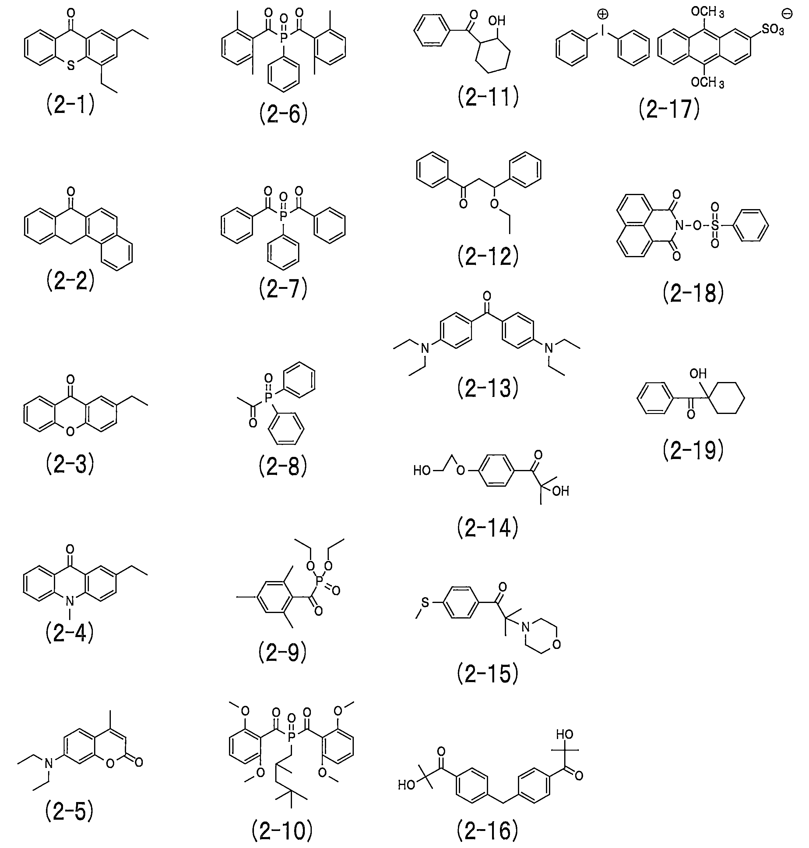
これらの光重合開始剤は、単独でもまたは2種以上組み合わせても使用することができるが、硬化性の観点から、2種以上の組み合わせが好ましい。また、本発明では、特開2016-155256号公報に開示された光重合開始剤を用いてもよい。
ハードコート層形成材料の総質量に対する(d)光重合開始剤の配合割合は、全固形分に対して0.01~5質量%以上であることが好ましい。配合割合が少な過ぎると、ハードコート層3が十分な架橋密度が得られず、耐傷性が劣化するため、0.01質量%以上であることが好ましい。配合割合が多過ぎると、光重合開始剤がブリードして、ハードコート層3の透過率(ヘイズ)が劣化してしまうため、5質量%以下が好ましい。
(e)熱線遮蔽微粒子
熱線遮蔽微粒子は、赤外線吸収性を有する金属酸化物微粒子であって、熱線遮蔽性に観点から、タングステン酸化物が好ましく、セシウム含有複合タングステン酸化物がさらに好ましい。
熱線遮蔽微粒子は、赤外線吸収性を有する金属酸化物微粒子であって、熱線遮蔽性に観点から、タングステン酸化物が好ましく、セシウム含有複合タングステン酸化物がさらに好ましい。
セシウム含有複合タングステン酸化物の組成は、特に制限されないが、安全性の観点から、一般式:CsxWyOzで表される酸化物であることが好ましく、たとえば、特開2013-64042号や特開2010-215451号公報に開示されるものと同様のものを使用することができる。
一般式において、Csはセシウムを表し、Wはタングステンを表し、Oは酸素を表す。x、yおよびzは、組成比を表し、タングステンとCsとの組成比(x/y)が、0.001以上1以下(0.001≦x/y≦1)を満たし、タングステンと酸素との組成比(z/y)が、2.0以上3.5以下(2.0≦z/y≦3.5)を満たすものが好ましい。
セシウム含有複合タングステン酸化物微粒子の平均粒径(平均一次粒子径、直径)は、可視光の反射を抑制しつつ、熱線吸収効果を確保できること、また散乱によるヘイズの劣化が生じず、透明性を確保できることから、5~150nmであることが好ましく。
セシウム含有複合タングステン酸化物微粒子としては、Cs0.33WO3が好ましく、たとえば、住友金属鉱山株式会社製のYMF-02A等の市販品が用いられる。
ハードコート層形成材料の総質量に対する(e)熱線遮蔽微粒子の配合割合は、全固形分に対して、5~40質量%であることが好ましい。配合割合が少な過ぎると、ハードコート層3の収縮に起因する光学フィルム1のカールが発生しやすく、熱割れが発生しやすくなるため、5質量%以上が好ましい。配合割合が多過ぎると、光学フィルム1の使用環境下において熱線遮蔽微粒子の凝集が発生しやすくなり、光学フィルム1の経時によるヘイズ変化が抑制しにくくなるため、40質量%以下が好ましい。
ハードコート層形成材料に(e)熱線遮蔽微粒子が配合されている際の、(a)多官能(メタ)アクリレート系化合物の配合割合は全固形分に対して40~85質量%、(b)2官能(メタ)アクリレート系化合物の配合割合は全固形分に対して5~25質量%、(c)2官能シリコーン(メタ)アクリレート系化合物の配合割合は全固形分に対して0.01~1質量%であることが好ましい。
熱線遮蔽微粒子は、セシウム含有複合タングステン酸化物以外の熱線遮蔽性金属酸化物であってもよく、たとえば、酸化亜鉛、アンチモンドープト酸化亜鉛(AZO)、インジウムドープト酸化亜鉛(IZO)、ガリウムドープト酸化亜鉛(GZO)、アルミニウムドープト酸化亜鉛、酸化錫、アンチモンドープト酸化錫(ATO)、インジウムドープト酸化錫(ITO)などであってもよい。
ハードコート層形成材料は、必要に応じて、(a)~(e)成分以外の各種添加剤等の任意成分を含んでもよい。塗布液のレベリング性、撥水性、滑り性等を付与するために、添加剤として、界面活性剤を含むことが好ましい。また、添加剤としては、塗布液乾燥剤として機能する金属石鹸、紫外線照射による硬化性を向上させるための染料、顔料、増感剤等であってもよい。
界面活性剤の種類として、特に制限はなく、フッ素系界面活性剤、アクリル系界面活性剤、シリコーン系界面活性剤等を用いることができる。特に塗布液のレベリング性、撥水性、滑り性という観点で、フッ素系界面活性剤を用いることが好ましい。フッ素系界面活性剤の例としては、たとえば、DIC株式会社製のメガファック(登録商標)Fシリーズ(F-430、F-477、F-552~F-559、F-561、F-562等)等の市販品を使用することができる。また、ハードコート層形成材料の総質量に対する界面活性剤の配合割合は、全固形分に対して0.001~0.1質量%であることが好ましい。
<光学フィルムの他の形態>
図1に示すように、本発明に係る光学フィルム1は、基材層2およびハードコート層3以外に、粘着層4およびセパレータ5を有するものが好ましい。
基材層2およびハードコート層3については前記のとおりであるので、粘着層4およびセパレータ5について、以下に説明する。
図1に示すように、本発明に係る光学フィルム1は、基材層2およびハードコート層3以外に、粘着層4およびセパレータ5を有するものが好ましい。
基材層2およびハードコート層3については前記のとおりであるので、粘着層4およびセパレータ5について、以下に説明する。
(粘着層)
粘着層4の構成する粘着層材料としては、特に制限されず、例えば、ドライラミネート剤、ウエットラミネート剤、粘着剤、ヒートシール剤、ホットメルト剤等のいずれもが用いられ、粘着剤が好ましい。粘着剤としては、特に制限されないが、例えば、ポリエステル系樹脂、ウレタン系樹脂、ポリ酢酸ビニル系樹脂、アクリル系樹脂、ニトリルゴム等が用いられる。
粘着層4の構成する粘着層材料としては、特に制限されず、例えば、ドライラミネート剤、ウエットラミネート剤、粘着剤、ヒートシール剤、ホットメルト剤等のいずれもが用いられ、粘着剤が好ましい。粘着剤としては、特に制限されないが、例えば、ポリエステル系樹脂、ウレタン系樹脂、ポリ酢酸ビニル系樹脂、アクリル系樹脂、ニトリルゴム等が用いられる。
粘着層4の厚さは、特に制限されないが、好ましくは3~25μmであり、より好ましくは5~20μmである。厚さを25μm以下とすることによって、ハードコート層3の硬度を維持することができる。一方、厚さを3μm以上とすることにより、応力によるハードコート層3の割れを防ぐことができる。
(セパレータ)
セパレータ5としては、特に制限されないが、基材および剥離層を有することが好ましい。剥離層には、任意の適切な樹脂を用いることができる。樹脂には、シリコン樹脂、フッ素系樹脂、メラミン樹脂、エポキシ樹脂、これらの樹脂混合物、シリコーン等の剥離剤を練り込んだ樹脂等が用いられる。基材としては、プラスチックフィルム、不織布、紙等からなる基材を用いる。また、セパレータ5としては、市販品を用いてもよく、たとえば、東山フィルム株式会社製のクリーンセパHYシリーズを好適に用いることができる。セパレータ5の厚さは、特に制限されないが、好ましくは10~50μmであり、より好ましくは15~40μmである。厚さを10μm以上とすることによって、熱成形時にセパレータの急激な熱収縮による成形不良を防ぐことができる。一方、厚さを50μm以下とすることにより、熱成形時により速く熱を基材やハードコート層に伝達することができるため、熱成形時間を短縮することができる。
セパレータ5としては、特に制限されないが、基材および剥離層を有することが好ましい。剥離層には、任意の適切な樹脂を用いることができる。樹脂には、シリコン樹脂、フッ素系樹脂、メラミン樹脂、エポキシ樹脂、これらの樹脂混合物、シリコーン等の剥離剤を練り込んだ樹脂等が用いられる。基材としては、プラスチックフィルム、不織布、紙等からなる基材を用いる。また、セパレータ5としては、市販品を用いてもよく、たとえば、東山フィルム株式会社製のクリーンセパHYシリーズを好適に用いることができる。セパレータ5の厚さは、特に制限されないが、好ましくは10~50μmであり、より好ましくは15~40μmである。厚さを10μm以上とすることによって、熱成形時にセパレータの急激な熱収縮による成形不良を防ぐことができる。一方、厚さを50μm以下とすることにより、熱成形時により速く熱を基材やハードコート層に伝達することができるため、熱成形時間を短縮することができる。
光学フィルム1は、基材層2の一方の表面にハードコート層3が配置され、基材層2の他方の表面に粘着層4およびセパレータ5がこの順に配置された層構造であることが好ましい。光学フィルム1がこのような層構造であることによって、ハードコート層3が光学フィルム1の最表面に配置されることとなり、光学フィルム1の熱成形の際に積極的に熱収縮することが可能となるため、光学フィルム1の熱成形性が向上する。
<光学フィルムの製造方法>
本発明に係る光学フィルム1の製造方法は、ハードコート層用塗布液調製工程と、ハードコート層用塗膜形成工程と、ハードコート層形成工程とを含むものである。以下、各工程について、説明する。
本発明に係る光学フィルム1の製造方法は、ハードコート層用塗布液調製工程と、ハードコート層用塗膜形成工程と、ハードコート層形成工程とを含むものである。以下、各工程について、説明する。
(ハードコート層用塗布液調製工程)
ハードコート層用塗布液調製工程は、前記(a)~(d)または(a)~(e)からなるハードコート層形成材料を溶媒に溶解して、ハードコート層用塗布液とする工程である。
ハードコート層用塗布液調製工程は、前記(a)~(d)または(a)~(e)からなるハードコート層形成材料を溶媒に溶解して、ハードコート層用塗布液とする工程である。
ここで、溶媒は、特に制限されないが、たとえば、水、炭化水素類(トルエン、キシレン)、アルコール類(メタノール、エタノール、イソプロパノール、ブタノール、シクロヘキサノール)、ケトン類(アセトン、メチルエチルケトン、メチルイソブチルケトン)、エステル類(酢酸メチル、酢酸エチル、乳酸メチル)、グリコールエーテル類、その他の有機溶媒等の中から適宜選択し、または、これらを混合し利用できる。
ハードコート層用塗布液における溶媒の含有量は、特に制限されないが、たとえば、塗布液の総質量に対して10~80質量%程度であり、より好ましくは20~80質量%であり、さらに好ましくは20~70質量%である。
(ハードコート層用塗膜形成工程)
前工程で調整されたハードコート層用塗布液を、基材層2の表面に塗布、乾燥してハードコート層用塗膜を形成する工程である。
前工程で調整されたハードコート層用塗布液を、基材層2の表面に塗布、乾燥してハードコート層用塗膜を形成する工程である。
ここで、塗布方法については、特に制限はなく、公知の手法、たとえば、ワイヤーバーによるコーティング、スピンコーティング、ディップコーティングなどの手法が採用されうる。また、ダイコーター、グラビアコーター、コンマコーターなどの連続塗布装置でも塗布することが可能である。
塗布後の乾燥条件としては、特に制限されないが、たとえば、乾燥温度が40~100℃、乾燥時間が0.5~10分であることが好ましい。
(ハードコート層形成工程)
前工程で形成されたハードコート層用塗膜に、紫外線等の光を照射して塗膜を硬化させて、ハードコート層3を形成する工程である。その結果、基材層2の一方の表面にハードコート層3が形成された光学フィルム1が製造される。
前工程で形成されたハードコート層用塗膜に、紫外線等の光を照射して塗膜を硬化させて、ハードコート層3を形成する工程である。その結果、基材層2の一方の表面にハードコート層3が形成された光学フィルム1が製造される。
ハードコート層用塗膜への紫外線等の照射は、塗膜の基材層2から遠い表面側から照射し、塗膜を硬化させる。この際の紫外線等の照射波長、照度、光量等の条件は、使用するハードコート層形成材料である(a)~(d)成分の種類によって異なるため、当業者によって適宜条件が調整されうる。たとえば、紫外線ランプを用いる場合、その照度は50~1500mW/cm2が好ましく、照射エネルギー量は50~1500mJ/cm2が好ましい。光学フィルム1において、照度としては80~1000mW/cm2が好ましい。さらに、照射エネルギー量は100~1000mJ/cm2が好ましい。さらに、必要に応じて紫外線照射雰囲気を窒素に置換してもよい。置換する際の残存酸素量は1質量%以下が好ましく、より好ましくは1000ppm以下である。
また、光学フィルム1が、粘着層4およびセパレータ5を有する場合には、前記のハードコート層形成工程の後に、以下の粘着層形成工程および積層・貼合工程を行う。
(粘着層形成工程)
前記のハードコート層用塗膜形成工程と同様の塗布方法で、セパレータ5の表面に、粘着層形成材料を溶媒に溶解した粘着層用塗布液を塗布・乾燥して、粘着層4を形成する工程である。
前記のハードコート層用塗膜形成工程と同様の塗布方法で、セパレータ5の表面に、粘着層形成材料を溶媒に溶解した粘着層用塗布液を塗布・乾燥して、粘着層4を形成する工程である。
(積層・貼合工程)
従来公知のラミネート方法で、ハードコート層3が形成された基材層2に、粘着層4が形成されたセパレータ5を積層・貼合工程である。積層・貼合は、ハードコート層3が形成されていない基材層2の表面と、粘着層4の表面との間で行う。その結果、ハードコート層3、基材層2、粘着層4およびセパレータ5がこの順で積層・貼合された光学フィルム1が製造される。
従来公知のラミネート方法で、ハードコート層3が形成された基材層2に、粘着層4が形成されたセパレータ5を積層・貼合工程である。積層・貼合は、ハードコート層3が形成されていない基材層2の表面と、粘着層4の表面との間で行う。その結果、ハードコート層3、基材層2、粘着層4およびセパレータ5がこの順で積層・貼合された光学フィルム1が製造される。
<光学フィルムの用途>
本発明に係る光学フィルムは、前記したように優れた熱成形性および耐傷性を有するため、ウィンドウフィルムおよび加飾フィルムに好適に用いられる。
本発明に係る光学フィルムは、前記したように優れた熱成形性および耐傷性を有するため、ウィンドウフィルムおよび加飾フィルムに好適に用いられる。
本発明の光学フィルム1をウィンドウフィルムとして用いる場合には、車外すなわちウィンドウガラスの外側に、ハードコート層3がウィンドウ側になるように配置される。そして、セパレータ5側をヒートガンで加熱することによって、ハードコート層3が熱収縮して、光学フィルム1が熱成形される。
その際、本発明の光学フィルム1では、光学フィルム1の最表面側に配置されるハードコート層3が積極的に熱収縮するため、光学フィルム1はハードコート層3側にカールして、ウィンドウガラスに追従する。そのため、熱成形後の光学フィルム1をウィンドウガラスの内側に貼合する際に、光学フィルム1がウィンドウガラスにピッタリならうため、水貼りやスキージによる水抜きが容易となる。
本発明の光学フィルム1を加飾フィルムとして用いる場合には、光学フィルム1は、基材層2とハードコート層3との間、または、基材層2と粘着層4との間に、装飾性を与える加飾層(図示せず)をさらに有する。加飾層とは、以下に示すようなものである。
(加飾層)
加飾層は、種々の模様(絵柄)をインキ組成物と印刷機を使用して印刷することにより形成される。また、加飾層の厚さは、その模様(絵柄)により適宜選択される。
加飾層は、種々の模様(絵柄)をインキ組成物と印刷機を使用して印刷することにより形成される。また、加飾層の厚さは、その模様(絵柄)により適宜選択される。
印刷方法としては、グラビア印刷などの通常の印刷方法を採用できる。加飾層は透明フィルム(図示せず)上に印刷して基材層2上に積層してもよいし、基材層2上に印刷してもよいが、製造上の観点からは透明フィルム上に印刷して基材層2に積層することが好ましい。ここで、インキ組成物としては、樹脂などから構成されるバインダーに顔料、染料などの着色剤、体質顔料、溶剤、安定剤、可塑剤、触媒、硬化剤などを適宜混合したものが使用される。
模様(絵柄)としては、木目模様、大理石模様(例えばトラバーチン大理石模様)などの岩石の表面を模した石目模様、布目や布状の模様を模した布地模様、タイル貼模様、煉瓦積模様などがあり、これらを複合した寄木、パッチワークなどの模様もある。これらの模様は通常の黄色、赤色、青色、及び黒色のプロセスカラーによる多色印刷によって形成される他、模様を構成する個々の色の版を用意して行う特色による多色印刷などによっても形成される。
以下、実施例を挙げて本発明を具体的に説明するが、本発明はこれらに限定されるものではない。
(ハードコート層用塗布液の調製)
下記に示すハードコート層形成材料を用いて、表1に示す配合割合のハードコート層用塗布液を調整した。なお、溶媒としてはメチルイソブチルケトンを用いた。
(a)多官能(メタ)アクリレート系化合物
a1:アロニックスM-402(東亞合成株式会社製)
a2:アロニックスM-408(東亞合成株式会社製)
(b)2官能(メタ)アクリレート系化合物
b1:IRR214-K(ダイセル・オルネクス株式会社製)
b2:A-DCP(新中村化学工業株式会社製)
(c)シリコーン(メタ)アクリレート系化合物
c1:EBECRYL350(ダイセル・オルネクス株式会社製)
c2:X-22-2445(信越シリコーン株式会社製)
(d)光重合開始剤
d1:Irgacure(登録商標)184(BASFジャパン株式会社製)
d2:Irgacure819(BASFジャパン株式会社製)
(e)熱線遮蔽微粒子
e1:YMF-02A(住友金属鉱山株式会社製)
下記に示すハードコート層形成材料を用いて、表1に示す配合割合のハードコート層用塗布液を調整した。なお、溶媒としてはメチルイソブチルケトンを用いた。
(a)多官能(メタ)アクリレート系化合物
a1:アロニックスM-402(東亞合成株式会社製)
a2:アロニックスM-408(東亞合成株式会社製)
(b)2官能(メタ)アクリレート系化合物
b1:IRR214-K(ダイセル・オルネクス株式会社製)
b2:A-DCP(新中村化学工業株式会社製)
(c)シリコーン(メタ)アクリレート系化合物
c1:EBECRYL350(ダイセル・オルネクス株式会社製)
c2:X-22-2445(信越シリコーン株式会社製)
(d)光重合開始剤
d1:Irgacure(登録商標)184(BASFジャパン株式会社製)
d2:Irgacure819(BASFジャパン株式会社製)
(e)熱線遮蔽微粒子
e1:YMF-02A(住友金属鉱山株式会社製)
(ハードコート層用塗膜の形成)
基材層(厚さ50μmのポリエチレンテレフタレートフィルム、コスモシャイン(登録商標)A4300、東洋紡株式会社製)の上に、前記のハードコート層用塗布液をグラビアコーターで塗布し、90℃で1分間乾燥させ、塗膜を形成した。
基材層(厚さ50μmのポリエチレンテレフタレートフィルム、コスモシャイン(登録商標)A4300、東洋紡株式会社製)の上に、前記のハードコート層用塗布液をグラビアコーターで塗布し、90℃で1分間乾燥させ、塗膜を形成した。
(ハードコート層の形成)
紫外線ランプを用いて、照度100mW/cm2、照射量0.2J/cm2、酸素濃度200ppmの条件で、塗膜の基材層から遠い面側から紫外線を照射することにより、塗膜を硬化させて、厚さが3μmのハードコート層を形成した。
紫外線ランプを用いて、照度100mW/cm2、照射量0.2J/cm2、酸素濃度200ppmの条件で、塗膜の基材層から遠い面側から紫外線を照射することにより、塗膜を硬化させて、厚さが3μmのハードコート層を形成した。
(光学フィルムの作製)
セパレータ(東洋紡社製、厚さ25μm)の上に、アクリル樹脂からなる厚さ10μmの粘着層を、グラビアコーターを用いて作製した。作製した粘着層の上に、ハードコート層が形成された基材層をラミネートし、光学フィルムとした。
セパレータ(東洋紡社製、厚さ25μm)の上に、アクリル樹脂からなる厚さ10μmの粘着層を、グラビアコーターを用いて作製した。作製した粘着層の上に、ハードコート層が形成された基材層をラミネートし、光学フィルムとした。
作製した光学フィルム(試料No.1~7)を用いて、熱成形性試験、耐傷性試験を以下の手順で行い、熱成形性、耐傷性を評価した。その結果を表1に示す。
(熱成形性試験)
光学フィルム(試料No.1~7)を、車のフロントガラスに、ヒートガンで300℃の温度設定で、熱成形した。作業者1名、作業時間8時間で熱成形できた車の台数で、熱成形性を以下のように評価した。
光学フィルム(試料No.1~7)を、車のフロントガラスに、ヒートガンで300℃の温度設定で、熱成形した。作業者1名、作業時間8時間で熱成形できた車の台数で、熱成形性を以下のように評価した。
◎:50台以上
○:40台以上50台未満
△:30台以上40台未満
×:30台未満
前記評価のうち、40台以上(◎、○)を熱成形性が良好、40台未満(△、×)を熱成形性が不良とした。
○:40台以上50台未満
△:30台以上40台未満
×:30台未満
前記評価のうち、40台以上(◎、○)を熱成形性が良好、40台未満(△、×)を熱成形性が不良とした。
(耐傷性試験)
光学フィルム(試料No.1~7)を、ヘイドン社製の荷重変動型摩擦摩耗試験システムHHS2000を用いて、荷重50g、スピード500mm/ms、距離50mmで10往復、スチールウール#0000番を用いて擦った。擦る前と後のヘイズ値を室温にて、ヘイズメータ(日本電色工業社製、NDH2000)を用いて測定し、その差で耐傷性を以下のように評価した。
光学フィルム(試料No.1~7)を、ヘイドン社製の荷重変動型摩擦摩耗試験システムHHS2000を用いて、荷重50g、スピード500mm/ms、距離50mmで10往復、スチールウール#0000番を用いて擦った。擦る前と後のヘイズ値を室温にて、ヘイズメータ(日本電色工業社製、NDH2000)を用いて測定し、その差で耐傷性を以下のように評価した。
◎:ヘイズ値の差が、0.5%未満
○:ヘイズ値の差が、0.5%以上1.0%未満
△:ヘイズ値の差が、1.0%以上3.0%未満
×:ヘイズ値の差が、3.0%以上
前記評価のうち、ヘイズ値の差が1.0%未満を耐傷性が良好、1.0%以上を耐傷性が不良とした。
○:ヘイズ値の差が、0.5%以上1.0%未満
△:ヘイズ値の差が、1.0%以上3.0%未満
×:ヘイズ値の差が、3.0%以上
前記評価のうち、ヘイズ値の差が1.0%未満を耐傷性が良好、1.0%以上を耐傷性が不良とした。
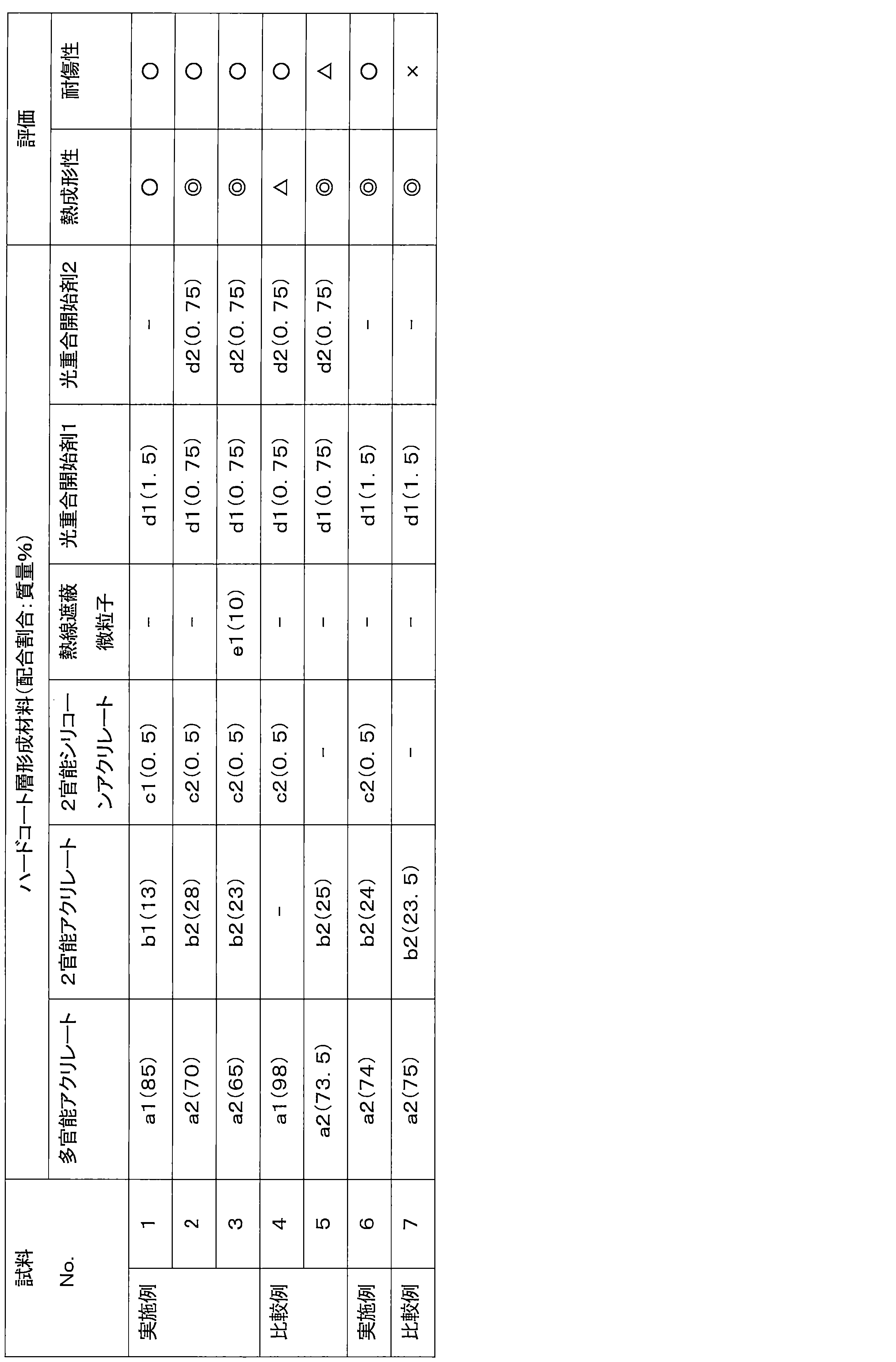
表1の結果より、試料No.1~3、6(実施例)は、本発明の要件を満足するため、熱成形性および耐傷性に優れていた。
一方、試料No.4(比較例)は、ハードコート層形成材料として(b)分子内に脂環構造を有する2官能(メタ)アクリレート系化合物を含んでいないため、熱成形性に劣っていた。試料No.5(比較例)は、ハードコート層形成材料として(c)2官能シリコーン(メタ)アクリレート系化合物を含んでいないため、耐傷性が劣っていた。試料No.7(比較例)は、ハードコート層形成材料として(c)2官能シリコーン(メタ)アクリレート系化合物を含んでいないため、耐傷性が劣っていた。
1 光学フィルム
2 基材層
3 ハードコート層
4 粘着層
5 セパレータ
2 基材層
3 ハードコート層
4 粘着層
5 セパレータ
Claims (6)
- 基材層と、前記基材層の一方の表面に配置したハードコート層と、を有し、前記ハードコート層は、下記(a)~(d)を含むハードコート層形成材料の硬化物からなることを特徴とする光学フィルム。
(a)3個以上の(メタ)アクリロイル基を有する多官能(メタ)アクリレート系化合物
(b)2個の(メタ)アクリロイル基を有し、分子中に脂環構造を有する2官能(メタ)アクリレート系化合物
(c)2個の(メタ)アクリロイル基を有する2官能シリコーン(メタ)アクリレート系化合物
(d)光重合開始剤 - 前記光重合開始剤が、2種以上の光重合開始剤からなることを特徴とする請求項1に記載の光学フィルム。
- 前記ハードコート形成材料が、熱線遮蔽微粒子をさらに含むことを特徴とする請求項1または請求項2に記載の光学フィルム。
- 前記基材層の一方の表面に前記ハードコート層が配置され、前記基材層の他方の表面に粘着層およびセパレータがこの順に配置された層構造であることを特徴とする請求項1から請求項3のいずれか1つに記載の光学フィルム。
- ウィンドウフィルムとして用いられることを特徴とする請求項4に記載の光学フィルム。
- 加飾フィルムとして用いられることを特徴とする請求項4に記載の光学フィルム。
Priority Applications (1)
| Application Number | Priority Date | Filing Date | Title |
|---|---|---|---|
| JP2019505779A JPWO2018168284A1 (ja) | 2017-03-17 | 2018-02-09 | 光学フィルム |
Applications Claiming Priority (2)
| Application Number | Priority Date | Filing Date | Title |
|---|---|---|---|
| JP2017-052192 | 2017-03-17 | ||
| JP2017052192 | 2017-03-17 |
Publications (1)
| Publication Number | Publication Date |
|---|---|
| WO2018168284A1 true WO2018168284A1 (ja) | 2018-09-20 |
Family
ID=63522389
Family Applications (1)
| Application Number | Title | Priority Date | Filing Date |
|---|---|---|---|
| PCT/JP2018/004664 Ceased WO2018168284A1 (ja) | 2017-03-17 | 2018-02-09 | 光学フィルム |
Country Status (2)
| Country | Link |
|---|---|
| JP (1) | JPWO2018168284A1 (ja) |
| WO (1) | WO2018168284A1 (ja) |
Cited By (3)
| Publication number | Priority date | Publication date | Assignee | Title |
|---|---|---|---|---|
| CN114316127A (zh) * | 2021-12-30 | 2022-04-12 | 上海绘兰材料科技有限公司 | 一种热敏胶主体树脂、太阳膜用热敏胶及其制备方法 |
| CN115746370A (zh) * | 2022-11-18 | 2023-03-07 | 江苏斯迪克新材料科技股份有限公司 | 一种哑光硬化半透明光学薄膜及其制备方法 |
| US11987733B2 (en) | 2019-09-27 | 2024-05-21 | Lg Chem, Ltd. | Acrylic adhesive composition, polarizing plate, and display device |
Citations (5)
| Publication number | Priority date | Publication date | Assignee | Title |
|---|---|---|---|---|
| JPH0762267A (ja) * | 1993-08-31 | 1995-03-07 | Sony Chem Corp | 紫外線硬化型塗料組成物 |
| JP2008105191A (ja) * | 2006-10-23 | 2008-05-08 | Fujifilm Corp | 光学フィルム、反射防止フィルム、偏光板、表示装置、及び光学フィルムの製造方法 |
| JP2013041086A (ja) * | 2011-08-15 | 2013-02-28 | Asahi Kasei E-Materials Corp | 光学素子 |
| JP2015030237A (ja) * | 2013-08-06 | 2015-02-16 | 大日本印刷株式会社 | 感熱紙 |
| WO2015142558A1 (en) * | 2014-03-17 | 2015-09-24 | Dow Corning Corporation | Curable composition cured product formed from the curable composition, and method of forming the cured product |
-
2018
- 2018-02-09 WO PCT/JP2018/004664 patent/WO2018168284A1/ja not_active Ceased
- 2018-02-09 JP JP2019505779A patent/JPWO2018168284A1/ja active Pending
Patent Citations (5)
| Publication number | Priority date | Publication date | Assignee | Title |
|---|---|---|---|---|
| JPH0762267A (ja) * | 1993-08-31 | 1995-03-07 | Sony Chem Corp | 紫外線硬化型塗料組成物 |
| JP2008105191A (ja) * | 2006-10-23 | 2008-05-08 | Fujifilm Corp | 光学フィルム、反射防止フィルム、偏光板、表示装置、及び光学フィルムの製造方法 |
| JP2013041086A (ja) * | 2011-08-15 | 2013-02-28 | Asahi Kasei E-Materials Corp | 光学素子 |
| JP2015030237A (ja) * | 2013-08-06 | 2015-02-16 | 大日本印刷株式会社 | 感熱紙 |
| WO2015142558A1 (en) * | 2014-03-17 | 2015-09-24 | Dow Corning Corporation | Curable composition cured product formed from the curable composition, and method of forming the cured product |
Cited By (3)
| Publication number | Priority date | Publication date | Assignee | Title |
|---|---|---|---|---|
| US11987733B2 (en) | 2019-09-27 | 2024-05-21 | Lg Chem, Ltd. | Acrylic adhesive composition, polarizing plate, and display device |
| CN114316127A (zh) * | 2021-12-30 | 2022-04-12 | 上海绘兰材料科技有限公司 | 一种热敏胶主体树脂、太阳膜用热敏胶及其制备方法 |
| CN115746370A (zh) * | 2022-11-18 | 2023-03-07 | 江苏斯迪克新材料科技股份有限公司 | 一种哑光硬化半透明光学薄膜及其制备方法 |
Also Published As
| Publication number | Publication date |
|---|---|
| JPWO2018168284A1 (ja) | 2020-01-16 |
Similar Documents
| Publication | Publication Date | Title |
|---|---|---|
| CN114174871B (zh) | 防反射膜 | |
| JP5998882B2 (ja) | 転写フィルムおよび転写フィルムの製造方法 | |
| KR101415840B1 (ko) | 하드코팅 필름 | |
| JP6597305B2 (ja) | 転写フィルム及びこれを用いた転写成形品 | |
| JP6375360B2 (ja) | 活性エネルギー線硬化性樹脂組成物、防曇防汚積層体、物品、及びその製造方法、並びに防汚方法 | |
| KR101045282B1 (ko) | 하드코팅층을 구비하는 장식 패널 및 그 제조 방법 | |
| KR20200144273A (ko) | 모바일 기기용 커버의 제조방법 | |
| JP6917534B2 (ja) | 積層フィルムおよび積層部材 | |
| TWI606932B (zh) | 高硬度膜 | |
| TW201441064A (zh) | 加飾用轉印薄膜 | |
| KR101886589B1 (ko) | 보호 필름, 필름 적층체 및 편광판 | |
| TWI482705B (zh) | 抗靜電層用硬化性樹脂組成物、光學薄膜、偏光板及顯示面板 | |
| JP2015163457A (ja) | インクジェット用記録シート、インクジェット用記録シートの製造方法、印刷物、印刷物の製造方法および装飾ガラス | |
| KR101103409B1 (ko) | 고광택 곡면 장식 패널 및 그 제조방법 | |
| WO2018168284A1 (ja) | 光学フィルム | |
| KR102063599B1 (ko) | 데코시트용 코팅 조성물 및 데코시트 | |
| JP6232879B2 (ja) | 転写シート及びそれを用いた被覆部材 | |
| JP2023106512A (ja) | 転写シート、加飾成形品及び加飾成形品の製造方法 | |
| KR20210106798A (ko) | 비산방지필름, 및 이를 포함하는 전자 디스플레이 및 전자장치 | |
| JP7074436B2 (ja) | 装飾シート、装飾シートを含む構造体及び装飾シートの製造方法 | |
| KR20230038142A (ko) | 인서트 성형용 하드 코트 필름 및 인서트 성형품의 제조방법 | |
| JP2012035560A (ja) | ハードコートフィルム及び反射防止フィルム | |
| WO2017073262A1 (ja) | 防曇積層体、物品、及びその製造方法、並びに防曇方法 | |
| KR102233234B1 (ko) | 플라스틱 적층체, 이의 제조방법 및 플라스틱 성형체 | |
| JP2023006496A (ja) | 積層フィルムおよび成形体、ならびにそれらの製造方法 |
Legal Events
| Date | Code | Title | Description |
|---|---|---|---|
| 121 | Ep: the epo has been informed by wipo that ep was designated in this application |
Ref document number: 18768258 Country of ref document: EP Kind code of ref document: A1 |
|
| ENP | Entry into the national phase |
Ref document number: 2019505779 Country of ref document: JP Kind code of ref document: A |
|
| NENP | Non-entry into the national phase |
Ref country code: DE |
|
| 122 | Ep: pct application non-entry in european phase |
Ref document number: 18768258 Country of ref document: EP Kind code of ref document: A1 |