WO2018168254A1 - エンジン - Google Patents
エンジン Download PDFInfo
- Publication number
- WO2018168254A1 WO2018168254A1 PCT/JP2018/003747 JP2018003747W WO2018168254A1 WO 2018168254 A1 WO2018168254 A1 WO 2018168254A1 JP 2018003747 W JP2018003747 W JP 2018003747W WO 2018168254 A1 WO2018168254 A1 WO 2018168254A1
- Authority
- WO
- WIPO (PCT)
- Prior art keywords
- fuel tank
- headlight
- upper cover
- mounting
- cover
- Prior art date
- Legal status (The legal status is an assumption and is not a legal conclusion. Google has not performed a legal analysis and makes no representation as to the accuracy of the status listed.)
- Ceased
Links
Images






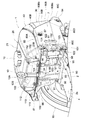
Classifications
-
- F—MECHANICAL ENGINEERING; LIGHTING; HEATING; WEAPONS; BLASTING
- F02—COMBUSTION ENGINES; HOT-GAS OR COMBUSTION-PRODUCT ENGINE PLANTS
- F02B—INTERNAL-COMBUSTION PISTON ENGINES; COMBUSTION ENGINES IN GENERAL
- F02B67/00—Engines characterised by the arrangement of auxiliary apparatus not being otherwise provided for, e.g. the apparatus having different functions; Driving auxiliary apparatus from engines, not otherwise provided for
-
- F—MECHANICAL ENGINEERING; LIGHTING; HEATING; WEAPONS; BLASTING
- F02—COMBUSTION ENGINES; HOT-GAS OR COMBUSTION-PRODUCT ENGINE PLANTS
- F02B—INTERNAL-COMBUSTION PISTON ENGINES; COMBUSTION ENGINES IN GENERAL
- F02B77/00—Component parts, details or accessories, not otherwise provided for
-
- F—MECHANICAL ENGINEERING; LIGHTING; HEATING; WEAPONS; BLASTING
- F21—LIGHTING
- F21S—NON-PORTABLE LIGHTING DEVICES; SYSTEMS THEREOF; VEHICLE LIGHTING DEVICES SPECIALLY ADAPTED FOR VEHICLE EXTERIORS
- F21S41/00—Illuminating devices specially adapted for vehicle exteriors, e.g. headlamps
-
- F—MECHANICAL ENGINEERING; LIGHTING; HEATING; WEAPONS; BLASTING
- F21—LIGHTING
- F21S—NON-PORTABLE LIGHTING DEVICES; SYSTEMS THEREOF; VEHICLE LIGHTING DEVICES SPECIALLY ADAPTED FOR VEHICLE EXTERIORS
- F21S43/00—Signalling devices specially adapted for vehicle exteriors, e.g. brake lamps, direction indicator lights or reversing lights
-
- F—MECHANICAL ENGINEERING; LIGHTING; HEATING; WEAPONS; BLASTING
- F21—LIGHTING
- F21S—NON-PORTABLE LIGHTING DEVICES; SYSTEMS THEREOF; VEHICLE LIGHTING DEVICES SPECIALLY ADAPTED FOR VEHICLE EXTERIORS
- F21S45/00—Arrangements within vehicle lighting devices specially adapted for vehicle exteriors, for purposes other than emission or distribution of light
-
- F—MECHANICAL ENGINEERING; LIGHTING; HEATING; WEAPONS; BLASTING
- F21—LIGHTING
- F21V—FUNCTIONAL FEATURES OR DETAILS OF LIGHTING DEVICES OR SYSTEMS THEREOF; STRUCTURAL COMBINATIONS OF LIGHTING DEVICES WITH OTHER ARTICLES, NOT OTHERWISE PROVIDED FOR
- F21V21/00—Supporting, suspending, or attaching arrangements for lighting devices; Hand grips
Definitions
- a fuel tank is disposed at the top of the engine body, a headlight is disposed on the front side of the fuel tank, and an upper cover that covers between the front portion of the fuel tank and the headlight is provided. It is related with the engine currently arranged.
- a front support body is fixed to the front end portion of the upper surface of a cylinder block of an engine body, and the front support body is mounted on the upper portion of the front support body.
- a headlight is fixed to the front center of the front support so as to penetrate in the front-rear direction.
- a front support is fixed to the front end portion of the upper surface of the cylinder block of the engine body, and the front and lower central portions of the front support are connected to the left and right sides of the light housing of the headlight.
- a mounting structure in which a protruding mounting piece is fixed with a screw or the like is disclosed.
- the front part of the seam welded joint flange of the fuel tank is fixed with a bolt or the like.
- a mounting piece extending downward from the inner surface of the upper cover is attached to a plate-like projecting piece extending in the left-right direction extending upward from the upper part of the light housing of the headlight. Etc. are concluded.
- a lower cover that covers the lower side between the front portion of the fuel tank and the headlight is fastened to the lower portion of the light housing with a screw or the like.
- flanges are formed at the peripheral edges of the side covers disposed on the left and right sides of the fuel tank so as to be bent toward the center in the left-right direction of the engine. Further, among the flanges of both side covers, the light mounting recesses into which the both side surfaces of the headlight enter are cut out in the flange corresponding to the left and right side surfaces of the lens portion of the headlight.
- the plate-like projecting piece to which the upper cover is fastened is a thin sheet metal that extends upward from the upper part of the light housing of the headlight, and the front-rear direction It is also easy to bend and deform. Therefore, the positioning accuracy of the upper cover with respect to the fuel tank is lowered, and there is a disadvantage that the upper cover is easily displaced.
- a lower cover that covers the lower side between the front lower end of the fuel tank and the lower end of the headlight is fastened to the lower portion of the light housing.
- the headlight is disposed in a space surrounded by the upper cover, the left and right side covers, and the lower cover. Therefore, the size of the headlight is limited, and it is difficult to freely design the shape and size of the headlight.
- a headlight is mounted on a light mounting recess formed in a flange portion corresponding to the left and right side portions of the lens portion of the headlight, out of the flanges of both side covers.
- Both side surface portions are arranged in an intrusive manner. Therefore, both side surface portions in the lens portion of the headlight are close to the outer surface sides of both side covers.
- there is a disadvantage that the possibility that both side portions of the lens portion of the headlight come into contact with other objects increases.
- the main object of the present invention is to provide an engine that can firmly mount the mounting portion of the upper cover, increase positioning accuracy, and suppress displacement of the upper cover with respect to the fuel tank. It is in.
- a fuel tank is disposed on an upper portion of an engine body, a headlight is disposed on a front portion side of the fuel tank, and a front portion of the fuel tank and the headlight are arranged.
- An engine having an upper cover that covers the space, The upper cover is directly fastened to the front portion of the joining flange of the fuel tank.
- the fuel tank is disposed in a state of being firmly fixed to the upper part of the engine body. Furthermore, as for the joining flange of the fuel tank, for example, the flange of the upper tank cover and the flange of the lower tank body are welded by seam welding. Thus, the plurality of flanges are in a highly rigid state joined in a superposed state. An upper cover that covers the space between the front part of the fuel tank and the headlight is directly fastened to the front part of the joint flange of the highly rigid fuel tank. As a result, the attachment portion of the upper cover can be constructed firmly. Furthermore, the positioning accuracy of the upper cover with respect to the fuel tank can be improved. Thereby, the position shift of the upper cover with respect to the fuel tank can be suppressed, and the appearance design can be improved.
- the headlight is disposed at a portion of a lower opening surrounded by the upper cover and front portions of side covers disposed on the left and right sides of the fuel tank. It is in.
- the light installation space surrounded by the upper cover and the front portions of both side covers opens downward. Therefore, there is no restriction on the design of the lower part of the headlight. And it becomes possible to make it the large lamp
- a front portion of the joining flange of the fuel tank is fixed to a front support body fixed to a cylinder block of the engine body, and a tank mounting site side of the front support body Is formed with a recess in which the mounting piece of the upper cover is engaged.
- the front part of the joint flange of the fuel tank is fixed to the front support body that is firmly attached to the cylinder block of the engine body.
- the upper cover is fastened directly to the front of the fixed strong and sturdy joint flange. Therefore, the positioning accuracy of the upper cover with respect to the fuel tank can be further improved.
- a recess is formed on the tank mounting site side of the front support to engage the mounting piece of the upper cover. Therefore, this recessed portion functions as a positioning portion that restricts the movement of the upper cover in the horizontal direction relative to the front portion of the joining flange of the fuel tank. Thereby, the positioning accuracy of the upper cover with respect to the fuel tank can be improved. Furthermore, the positional deviation of the upper cover can be eliminated.
- a fourth characteristic configuration according to the present invention is that a lower end edge of the upper cover is disposed below a front portion of the joining flange of the fuel tank.
- the seam welded portion at the front portion of the joint flange of the fuel tank can be covered with a simple appearance by simply modifying the position of the lower edge of the upper cover as described above.
- the width of the region corresponding to the left and right side surfaces of the lens portion of the headlight is configured to be wide at least on the front end side among the widths of the side covers in the left-right direction. It is in.
- the left and right side surfaces of the lens unit are equal in width to the left and right sides of the headlight in the region corresponding to the left and right side surfaces of the lens portion of the headlight. Is separated from the outer surface of the side cover. Thereby, the physical contact to the lens part of a headlight can be reduced, and protection of a headlight can be aimed at.
- the rigidity of the side cover in the wide area is improved. Therefore, the strength of both side covers can also be improved. And it can reduce that external force is transmitted to the right-and-left side of a headlight by a side cover field with high rigidity.
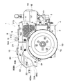
- the engine 1 shown in FIGS. 1 to 3 is a single-cylinder water-cooled horizontal diesel engine (hereinafter referred to as a horizontal engine).
- the engine longitudinal direction indicated by the arrow X in FIG. 1 is the front-rear direction
- the engine width direction indicated by the arrow Z in FIG. 1 is the left-right direction
- the height direction is the vertical direction.
- FIG. 2 shows a side view of the horizontal engine 1 as viewed from the right side, with the right side of the page being the front side and the left side of the page being the back side.
- FIG. 3 shows a side view of the horizontal engine 1 as viewed from the left side.
- the horizontal engine 1 includes an engine body 4 having a cylinder head 3 provided horizontally on the rear side of the cylinder block 2.
- a fuel tank 20 for storing the fuel of the horizontal engine 1 is disposed in the upper half of the cylinder block 2, and a radiator (see FIG. 4) for cooling the engine coolant is disposed in the upper half of the cylinder block 2. 5 including a cooling water tank).
- Headlights 30 are disposed on the front side of the fuel tank 20, and front side covers 7 are disposed on the left and right sides of the fuel tank 20.
- an upper cover that covers a mounting structure on the front side of the fuel tank 20 described later is provided between the front end of the tank cover 21 and the upper end of the headlight 30 of the fuel tank 20.
- a (top cover) 40 is provided.
- the upper cover 40 is formed in an inclined curved surface that rises rearward so that the curved surface of the lens portion 31 of the headlight 30 and the curved surface of the tank cover 21 of the fuel tank 20 are continuous.
- the headlight 30 is provided with a light having a lower opening surrounded by an upper cover 40 and a front portion of the left and right front side covers 7 disposed in a substantially gate shape (substantially inverted U shape) when viewed from the front. It is arranged in the space portion. Therefore, there is no restriction on the design of the lower part of the headlight 30, and it is possible to make the headlight 30 into a large lamp shape projecting downward from the headlight 30.
- the radiator 5 includes a rear upper cover 8 disposed substantially continuously to the rear end of the tank cover 21 of the fuel tank 20, and rear ends of the left and right front side covers 7. Are covered with left and right rear side covers 9 arranged in a substantially continuous state.
- a fuel cap 10 is provided at the center of the upper surface of the fuel tank 20.
- a radiator cap 11 of the radiator 5 and an eye bolt 12A that is a constituent member of a suspension bolt 12 for lifting the horizontal engine 1 at the center of gravity are provided.
- Each of the left and right rear side covers 9 is formed with a cooling vent 13 provided with a mesh.
- An air cleaner 15 and a muffler 16 are arranged in the left-right direction above the cylinder head 3 of the engine body 4.
- a gear case 17 is disposed on the right side surface of the cylinder block 2, and a crank gear, a cam gear, a lubricant pump drive gear, and the like are accommodated in the gear case 17 although not shown.
- crankshaft 18 is rotatably supported on the cylinder block 2 in a posture along the left-right direction, and a flywheel 19 is attached to the left end of the crankshaft 18.
- flywheel 19 By rotating the flywheel 19 when the horizontal engine 1 is started, rotational energy is stored to facilitate the start, and after the start, the rotation of the crankshaft 18 is stabilized.
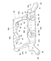
- a front support 50 made of aluminum die-casting extends over the upper surface 2 a and the front side surface (an example of a side surface of the cylinder block 2) 2 b on the front side of the cylinder block 2 of the engine body 4. Is installed.
- the upper surface 2a of the cylinder block 2 to which the front support 50 is attached is formed on a horizontal surface with high processing accuracy
- the front side surface 2b of the cylinder block 2 is a vertical surface with high processing accuracy. Is formed. Therefore, the front end upper corner of the cylinder block 2 is formed as a right angle corner where the upper surface 2a along the horizontal plane and the front side 2b along the vertical plane intersect.
- the front support 50 is provided with a lamp mounting opening 51 in which the reflecting surface constituting part 32A of the lamp housing 32 constituting the headlight 30 can enter and be arranged from the front side.
- a horizontally elongated annular frame 52 is provided.
- a horizontal mounting plate portion 53 and a vertical mounting plate portion 54 are integrally formed on the back side (rear side) of the lower horizontal frame portion 52 ⁇ / b> A of the annular frame portion 52.
- the horizontal mounting plate portion 53 has a horizontal horizontal mounting surface 53a that comes into contact with the upper surface 2a on the front side of the cylinder block 2 from above.
- the vertical mounting plate portion 54 has a pair of vertical left and right vertical mounting surfaces 54 a that abut against the front side surface 2 b of the cylinder block 2 from the front.
- the horizontal mounting surface 53a of the horizontal mounting plate portion 53 has a first screw hole 55 (see FIG. 4) formed in the upper surface 2a of the cylinder block 2 in the first direction from the vertical direction.
- a pair of left and right circular first bolt insertion holes 57 that are fastened by bolts 56 are formed.
- An insertion hole 60 is formed.
- Each of the second bolt insertion holes 60 is formed as a long hole along the vertical direction.
- the horizontal mounting surface 53 a of the horizontal mounting plate portion 53 is formed so as to protrude below the other horizontal lower side surface 53 b of the horizontal mounting plate portion 53 that is continuous therewith.
- the vertical mounting surface 54a of the vertical mounting plate portion 54 is also formed so as to protrude rearward from the other vertical rear side surface 54b of the vertical mounting plate portion 54 that is continuous therewith.
- the front support body 50 is attached over two surfaces of the upper surface 2a and the front side surface 2b of the cylinder block 2 which are tough and excellent in durability. Therefore, it becomes possible to firmly fix the front support body 50 with less vibration. Therefore, it is possible to reduce the stress generated in the front support 50 and improve the durability.
- the upper surface 2a and the front side surface 2b of the cylinder block 2 have high processing accuracy. Therefore, the positioning accuracy with respect to the cylinder block 2 at each of the front portion of the fuel tank 20 attached to the front support 50, the headlight 30, the upper cover 40, and the front portions of both front side covers 7 can be improved.
- the fuel tank 20 includes an upper sheet metal tank cover 21 that opens downward and a lower sheet metal tank body 22 that opens upward. .
- the annular flange formed integrally and projecting outward from the lower opening periphery of the tank cover 21 and the flange formed integrally projecting outward from the upper opening periphery of the tank body 22 are overlapped. In this state, it is welded in a sealed state by seam welding.
- a joining flange 23 is constituted by the flange of the tank cover 21 and the flange of the tank body 22 integrated by seam welding.
- the width is configured to be larger than the width (see FIGS. 5 and 7) of both lateral flange portions 23C protruding outward in the left-right direction.
- the tank cover 21 has a deformed hexagonal contour shape in which the left and right sides of the front portion are slightly tapered in plan view.
- the upper cover 40 is disposed on the outer surface side extending over.
- the front wall portion 22 ⁇ / b> A of the tank body 22 is formed with a lamp recess 24 into which the reflecting surface constituting portion 32 ⁇ / b> A in the lamp housing 32 of the headlight 30 enters from the front side.
- an inclined rear wall portion 22 b positioned on the front side is formed at the upper and lower intermediate portion of the rear wall portion 22 ⁇ / b> B of the tank body 22 as shown in FIG. 4.
- the first bracket 25 and the second bracket 26 are fixed to the left and right side wall portions 22 ⁇ / b> C of the tank body 22.
- the first bracket 25 is for attaching both rear end portions of the upper cover 40 with a first screw member 45 (see FIG. 7).
- the second bracket 26 is for attaching the front and rear intermediate portions of the front side cover 7 with sixth bolts 87.
- a horizontal placement support surface 52 b for placing and supporting the front flange portion 23 ⁇ / b> A of the fuel tank 20 is provided on the upper horizontal frame portion 52 ⁇ / b> B of the annular frame portion 52 in the front support 50. Is formed.
- planes for forming attachment spaces with respect to the upper cover 40 are provided at two positions in the middle portion in the left-right direction of the upper horizontal frame portion 52 ⁇ / b> B provided with the placement support surface 52 b.
- a substantially flat U-shaped concave portion 61 is cut out. Therefore, as shown in FIGS.
- both the left and right side portions and the left and right center portion defined by the two concave portions 61 are arranged in front of the fuel tank 20. It is comprised in the tank attaching part 62 with respect to the flange part 23A.
- Each tank mounting portion 62 is configured to be thicker than other portions of the upper horizontal frame portion 52B of the annular frame portion 52, and the front flange portion 23A of the fuel tank 20 is screwed and fixed to each tank mounting portion 62.
- a third screw hole 63 for the third bolt 69 is formed.
- a contour shape close to the contour shape of the mounting support surface 52b is provided between the mounting support surface 52b of the front support 50 and the lower surface of the front flange portion 23A of the fuel tank 20.
- the lower vibration-proof rubber 65 formed in the bottom is interposed.
- the lower anti-vibration rubber 65 has first bolts of the same shape corresponding to the third bolt insertion holes 65a corresponding to the third screw holes 63 of the upper horizontal frame portion 52B and the recesses 61 of the upper horizontal frame portion 52B.
- a recess 65b is formed.
- an upper anti-vibration rubber 66 formed in a contour shape close to the contour shape of the mounting support surface 52b, and A metal holding plate 67 is provided.
- the upper anti-vibration rubber 66 includes a fourth bolt insertion hole 66a corresponding to each third screw hole 63 of the upper horizontal frame portion 52B and a second concave portion 66b having the same shape corresponding to each concave portion 61 of the upper horizontal frame portion 52B. Is formed.
- the holding plate 67 is also formed with a fifth bolt insertion hole 67a corresponding to each third screw hole 63 of the upper horizontal frame portion 52B and a third recess 67b having the same shape corresponding to each recess 61 of the upper horizontal frame portion 52B.
- sixth bolt insertion holes 68 corresponding to the third screw holes 63 of the upper horizontal frame portion 52 ⁇ / b> B are formed in the front flange portion 23 ⁇ / b> A of the fuel tank 20.
- each sixth bolt insertion hole 68 As shown in FIGS. 7 and 8, between the inner surface of each sixth bolt insertion hole 68 and the outer surface of each third bolt 69 in the front flange portion 23A of the fuel tank 20, and above the front support 50. Between the upper surface of the horizontal frame portion 52 ⁇ / b> B and the lower surface of the pressing plate 67, a metallic cylindrical positioning collar 73 is fitted and mounted. The outer peripheral surface of each collar 73 is formed in an octagon (may be formed in a polygon or a circle other than an octagon).
- the fourth bolt insertion holes 66a of the upper vibration isolating rubber 66 in contact with or close to the collar 73, the sixth bolt insertion holes 68 of the front flange portion 23A, and the third bolt insertion holes 65a of the lower vibration isolating rubber 65 are also 8. It is formed in a square shape.
- the lower end portion of the collar 73 is fitted to the upper portion of the third screw hole 63 positioned at the left and right outer ends of the third screw holes 63 formed in the upper horizontal frame portion 52B of the front support 50.
- a mating octagonal fitting hole 63a is formed.
- the fuel tank is placed on the mounting support surface 52 b of the front support 50 fixed to the cylinder block 2 via the lower vibration isolating rubber 65.
- 20 front flange portions 23A are placed.
- the presser plate 67 is applied to the upper surface of the front flange portion 23 ⁇ / b> A of the fuel tank 20 via the upper vibration-proof rubber 66.
- a metallic cylindrical positioning collar 73 is fitted and mounted. Further, as shown in FIG. 8, the lower ends of the collars 73 located at the left and right outer ends are fitted into fitting holes 63 a formed in the upper part of the third screw holes 63. And the lower end of the collar 73 located in the center of the left and right is in contact with the mounting support surface 52b of the upper horizontal frame portion 52B.
- the third bolts 69 inserted into the fifth bolt insertion holes 67 a of the presser plate 67 are inserted into the fourth bolts of the upper vibration-proof rubber 66.
- the holes 66a, the sixth bolt insertion holes 68 of the front flange portion 23A of the fuel tank 20 and the third bolt insertion holes 65a of the lower vibration isolating rubber 65 pass through the first horizontal frame portion 52B of the front support 50.
- the three screw holes 63 are screwed and fixed.
- the front flange portion 23 ⁇ / b> A of the fuel tank 20 is attached to the upper horizontal frame portion 52 ⁇ / b> B of the front support 50 that is firmly attached over the two surfaces of the upper surface 2 a and the front side surface 2 b of the cylinder block 2. Place. Furthermore, it fastens in the state which interposed the vibration isolating rubbers 65 and 66 on the upper and lower sides of the front flange part 23A of the fuel tank 20. Therefore, the front part of the fuel tank 20 can be attached with little vibration.
- each sixth bolt insertion hole 68 of the front flange portion 23A of the fuel tank 20 and the outer surface of each third bolt 69, and the upper surface of the upper horizontal frame portion 52B of the front support 50 and the presser foot Since a metallic cylindrical positioning collar 73 is fitted and mounted between the lower surface of the plate 67, the front portion of the fuel tank 20 can be firmly attached. Further, the collars 73 positioned on the left and right outer ends are fitted into the sixth bolt insertion holes 68 of the front flange portion 23A of the fuel tank 20, and the third screw in the upper horizontal frame portion 52B of the front support 50 is provided. It fits into a fitting hole 63 a formed in the upper part of the hole 63.
- the upper cover 40 includes a central cover portion 40A and left and right inclined cover portions 40B.
- the center cover portion 40 ⁇ / b> A faces the front end wall portion 21 ⁇ / b> A of the tank cover 21 of the fuel tank 20.
- Both the inclined cover portions 40B face the left and right inclined wall portions 21B of the tank cover 21 in a state of being continuous on both the left and right sides of the central cover portion 40A.
- both first recesses 61 formed in the upper horizontal frame portion 52 ⁇ / b> B of the front support 50 and the first anti-vibration rubber 65 are provided at the lower end edge of the center cover portion 40 ⁇ / b> A.
- a pair of left and right mounting pieces 40C that can be engaged with the concave portion 65b from the front side are bent.
- each attachment piece 40C is formed with a seventh bolt insertion hole 42 for the fourth bolt 41 inserted from below.
- each mounting piece 40C is the same as or slightly the same as the inner edge contour shape of the concave portion 61 of the upper horizontal frame portion 52B and the first concave portions 65b of the lower vibration isolating rubber 65. It is formed in an outline shape that is a small, substantially similar shape, and is substantially U-shaped in plan view. Therefore, when the upper cover 40 is attached to the front flange portion 23 ⁇ / b> A of the fuel tank 20, the outer edges of the attachment pieces 40 ⁇ / b> C of the upper cover 40 abut against the inner surfaces of the first recesses 65 b of the lower vibration-proof rubber 65. Or close.
- each mounting piece 40C functions as a positioning portion that restricts the movement of the upper cover 40 in the left-right direction relative to the front flange portion 23A of the fuel tank 20.
- the positioning accuracy can be improved, and the positional deviation of the upper cover 40 can be eliminated.
- both concave portions 61 of the upper horizontal frame portion 52 ⁇ / b> B of the front support 50 and both first concave portions 65 b of the lower vibration isolation rubber 65 are formed in the same shape.
- the inner surfaces of both concave portions 61 of the upper horizontal frame portion 52B and the inner surfaces of both first concave portions 65b of the lower vibration isolating rubber 65 are connected to the mounting pieces 40C of the upper cover 40 that are engaged from the front side. It functions as an engagement guide surface that guides to a predetermined engagement position.
- the engagement guide surface is a long surface in the vertical direction in which the thickness of the upper horizontal frame portion 52B and the thickness of the lower vibration isolating rubber 65 are combined. Therefore, the assembling work of the upper cover 40 can be facilitated.
- the eighth bolt is inserted into the front flange portion 23 ⁇ / b> A of the fuel tank 20 in a portion corresponding to the seventh bolt insertion hole 42 of the both attachment pieces 40 ⁇ / b> C of the upper cover 40.
- a hole 43 is formed.
- a nut 44 to which the fourth bolt 41 inserted from below into the eighth bolt insertion hole 43 is screwed is fixed to the upper surface of the front flange portion 23A.
- both inclined cover portions 40B of the upper cover 40 are screwed and fixed to the first bracket 25 (see FIG. 5) fixed to the side wall portion 22C of the tank body 22.
- a screw insertion hole 46 for the first screw member 45 is formed.
- the upper cover 40 attaches the upper cover 40.
- the attachment piece 40 ⁇ / b> C engages with both the 1st recessed parts 65b of the lower vibration-proof rubber 65 from the front side.
- the outer edges of the mounting pieces 40 ⁇ / b> C of the upper cover 40 are the inner surfaces of the recesses 61 of the upper horizontal frame portion 52 ⁇ / b> B and the first recesses 65 b of the lower vibration isolation rubber 65. Abuts or approaches each inner surface. Therefore, the positional deviation in the left-right direction of the upper cover 40 with respect to the front flange portion 23A of the fuel tank 20 is prevented.
- the fourth bolt 41 is inserted into the seventh bolt insertion hole 42 of each attachment piece 40 ⁇ / b> C of the upper cover 40 from below.
- the fourth bolt 41 is screwed and fixed to a nut 44 that passes through the eighth bolt insertion hole 43 of the front flange portion 23A of the fuel tank 20 and is fixed to the upper surface of the front flange portion 23A.
- the first screw member 45 is inserted into the screw insertion hole 46 formed in the rear end portion of the both inclined cover portions 40 ⁇ / b> B of the upper cover 40, and the side wall portion of the tank main body 22. It is screwed and fixed to the first bracket 25 of 22C.
- each attachment piece 40C of the upper cover 40 is configured to contact the lower surface of the front flange portion 23A, and therefore, the lower end edge of the upper cover 40 is more than the front flange portion 23A of the fuel tank 20. It is arranged below. As a result, in a state where the upper cover 40 is fixed to the front flange portion 23A of the fuel tank 20, the weld seam portion of the fuel tank 20 can be covered with the upper cover 40, and deterioration of the seam welded portion is suppressed. can do.
- the headlight 30 is configured by fitting and joining the peripheral portion of the lens portion 31 and the peripheral portion of the lamp housing 32 including the light source 29 in a watertight state.
- the lens portion 31 includes a front lens portion 31A that is bent in a substantially “ ⁇ ” shape when viewed from the side, and a side lens portion 31B that extends from the left and right sides of the front lens portion 31A toward the rear outward side.
- the lamp housing 32 extends from the both sides of the reflective surface constituting part 32A in the left-right direction of the reflecting part constituting part 32A to the rear outward side along both side lens parts 31B of the lens part 31. And a side cover portion 32B.
- Positioning pins 33 projecting horizontally on the rear side are provided on both sides.
- a mounting member 34 is horizontally provided on the rear side of the lamp housing 32 and on both sides in the left and right direction on the upper side that is displaced inward from the outer peripheral edge of the fitting between the lens portion 31 and the lamp housing 32. It is extended to.
- the mounting member 34 can be applied to the lower surface of the tank mounting portion 62 located on both sides in the left-right direction among the three tank mounting portions 62 of the front support 50.
- each of the corner portions formed by the lower horizontal frame portion 52A and the left and right vertical frame portions 52C in the annular frame portion 52 of the front support 50 is provided in the left and right sides.
- the arm part 70 extended toward the outward downward direction is integrally formed.
- a positioning engagement hole 71 for engaging both positioning pins 33 of the lamp housing 32 from the front-rear direction is formed in an intermediate portion between the both arm portions 70.
- fourth screw holes 72 for the second screw member 35 to be screwed in from below are formed in the left and right tank mounting portions 62 of the front support 50.
- the front end portions of both mounting members 34 of the lamp housing 32 can be engaged from the front with respect to the second screw members 35 screwed into the fourth screw holes 72 of both tank mounting portions 62 of the front support 50.
- a screw opening notch 34a is formed in the rear opening.
- both positioning pins 33 of the lamp housing 32 and positioning engagement holes formed in both arm portions 70 of the front support 50 in a state where both positioning pins 33 engage from the front-rear direction. 71 is provided. These positioning pins 33 and positioning engagement holes 71 constitute a positioning portion 36 for the front support 50 and the headlight 30.
- a second screw member 35 that passes through the notch 34 a and is screwed and fixed to the fourth screw hole 72 of the tank mounting portion 62 is provided.
- the attachment member 34, the fourth screw hole 72, and the second screw member 35 constitute a fastening portion 37 between the front support 50 and the headlight 30.
- the positioning portion 36 and the fastening portion 37 for the headlight 30 are provided only on the back side of the lamp housing 32 of the headlight 30.
- the positioning part 36 and the fastening part 37 for the headlight 30 are dispersed, for example, on the back surface of the lamp housing 32 and the side surface on the outer side of the outer peripheral edge of the lens part 31 and the lamp housing 32. Is provided.
- the shape of the side surface of the headlight 30 is not limited by the positioning portion 36 and the fastening portion 37. Therefore, there is no restriction on the design of the side surface form of the headlight 30, and the headlight 30 can be formed into a large lamp shape projecting to the side thereof.
- the headlight 30 is attached to the front support 50.
- the first attachment method the second screw member 35 is attached to the fourth screw holes 72 of both tank attachment portions 62 in advance.
- both the positioning pins 33 of the lamp housing 32 and the screw insertion notches 34a of the mounting members 34 are respectively engaged with the positioning engagement holes 71 and the second screw members 35 of the front support 50 from the front side.
- the second screw member 35 is finally tightened and fixed.
- the positioning pins 33 of the lamp housing 32 are engaged with the positioning engagement holes 71 of the front support 50 from the front side.
- the second screw member 35 is clamped and fixed to the fourth screw holes 72 of both tank mounting portions 62 through the screw insertion notches 34a of both mounting members 34 from below.
- the headlight 30 is mounted after the front support 50 is mounted, the fuel tank 20 is mounted, and the upper cover 40 is mounted.
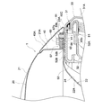
- the height position of the upper end edge of the lens portion 31 which is the uppermost end position of the headlight 30 is set to a position below the lower surface of each mounting piece 40C of the upper cover 40 as shown in FIG. Yes. Therefore, the headlight 30 is not contacted with the upper cover 40 when assembling.
- the upper end edge of the lens portion 31 of the headlight 30 and the lower end edge of the upper cover 40 are both formed in a straight line along the horizontal direction. As a result, the gap between the upper end edge of the lens portion 31 of the headlight 30 and the lower end edge of the upper cover 40 can appear to be apparently small.
- a flange 80 is bent and formed on the entire periphery of each front side cover 7 toward the inward side, which is the central side in the left-right direction of the horizontal engine 1. ing.
- the cover flange 80 includes an upper flange portion 80A, a bent flange portion 80B, a front end flange portion 80C, a lower flange portion 80D, and a rear flange portion 80E.
- the bent flange portion 80B is configured so as to follow the outer edge of the “ ⁇ ” shape (substantially laterally V-shaped) of the side lens portion 31B of the lens portion 31 in a state of being continuous with the front end of the upper flange portion 80A. .
- the front end flange portion 80C is configured to extend forward and downward from the front end of the bent flange portion 80B.
- the lower flange portion 80D is configured to extend rearward from the lower end of the front end flange portion 80C.
- the rear flange portion 80E is configured to connect the rear end of the upper flange portion 80A and the rear end of the lower flange portion 80D.
- the rear flange portion 80E is integrally formed with a connecting cover portion 81 that is fastened together with the front end portion of the rear side cover 9 in a superposed state.
- the width in the left-right direction (hereinafter referred to as the flange width) of the flange portion in the front side region corresponding to the lens portions 31B on both sides of the lens portion 31 is, in other words, The flange width of the front side region from the gently inclined flange portion 80Ba on the front half side of the bent flange portion 80B to the front end flange portion 80C is obtained.
- the flange width is larger than the flange width of the steeply inclined flange portion 80Bb on the rear half side of the bent flange portion 80B, and is formed in a tapered shape in which the flange width becomes wider toward the front end side.
- the flange width of the front region corresponding to the left and right side surfaces of the lens portion 31 of the headlight 30 among the flanges 80 of the both side covers 7 is configured to be wider than the flange widths of other portions. ing. Therefore, the left and right side surfaces of the lens portion 31 are separated from the outer surface of the side cover 7 by this wide width. Thereby, the physical contact to the lens part 31 of the headlight 30 can be reduced, and the headlight 30 can be protected.
- the rigidity of the side cover 7 in the wide area is improved. Therefore, the strength of both side covers 7 can also be improved, and transmission of external force to the left and right side surfaces of the headlight 30 due to the region of the side cover 7 having high rigidity can be reduced.
- the lens portion 31 of the headlight 30 is more effectively formed by forming the gently inclined flange portion 80Ba and the front end flange portion 80C on the front half side of the bent flange portion 80B into a tapered shape with the flange width becoming wider toward the front end side. Can be protected.
- each of the attachment portions 82 has a fifth bolt 84 with respect to the fifth bolt 84 inserted from a ninth bolt insertion hole (not shown) formed in the front end portion of the front side cover 7.
- Five screw holes 85 are formed.
- the sixth bolt 87 inserted from the tenth bolt insertion hole (not shown) formed in the front and rear intermediate portion of each front side cover 7
- the second bracket 26 fixed to each side wall portion 22C of the screw 22 is screwed and fixed.
- a rear support 90 made of aluminum die-casting is formed on the upper surface 2 a of the cylinder block 2 of the engine body 4 and between the fuel tank 20 and the radiator 5 in the left-right direction. Is installed.
- the rear support 90 is configured by integrally forming a plate-like base 92, a plate-like leg portion 93, a tank attachment plate portion 94, and a cover attachment plate portion 95.
- the plate-like base 92 is fixed to the upper surface 2 a of the cylinder block 2 with a plurality of seventh bolts 91.
- the plate-like leg portion 93 is configured in a plate shape extending upward from the plate-like base portion 92.
- the tank mounting plate portion 94 includes a horizontal mounting support surface for mounting and supporting the rear flange portion 23 ⁇ / b> B of the fuel tank 20 at the upper end position of the plate-like leg portion 93.
- the cover attaching plate portion 95 is configured in a plate shape extending laterally outward from the right side surface of the plate-like leg portion 93.
- thick first attachment portions 96 that fix the rear flange portion 23 ⁇ / b> B of the fuel tank 20 are formed on both sides in the left-right direction of the tank attachment plate portion 94.
- a thick second attachment portion 97 to which the connecting bolt 12B constituting the suspension bolt 12 is attached is formed at the center in the left-right direction of the tank attachment plate portion 94 corresponding to the substantially center position in the width direction of the horizontal engine 1.
- the connecting bolt 12 ⁇ / b> B screwed and fixed to the second mounting portion 97 has a length from the upper surface of the second mounting portion 97 to the upper surface of the rear upper surface cover 8.
- An eye bolt 12A is screwed and fixed to the upper end portion of the connecting bolt 12B.
- the rear flange portion 23 ⁇ / b> B of the fuel tank 20 is placed on the mounting support surface of the tank mounting plate portion 94 via the first vibration isolation rubber 100. Further, a third bracket 110 for mounting the rear upper surface cover 8 is placed on the upper surface of the rear flange portion 23 ⁇ / b> B of the fuel tank 20 via the second anti-vibration rubber 101. In this mounted state, the eighth bolt 102 is screwed and fixed to the first mounting portions 96 of the tank mounting plate portion 94 from above.
- the rear flange portion 23 ⁇ / b> B of the fuel tank 20 and the third bracket 110 are fastened together with the tank mounting plate portion 94 of the rear support 90 fixed to the upper surface 2 a of the cylinder block 2. .
- each collar is fitted and mounted.
- the outer peripheral surface of each collar is formed in an octagon (may be formed in a polygon or a circle other than an octagon).
- a bolt insertion hole (not shown) of the first vibration isolating rubber 100 in contact with or close to the collar, a bolt insertion hole of the rear flange portion 23B, and a bolt insertion hole (not shown) of the second vibration isolating rubber 101 are also formed in an octagon. ing. Further, an octagonal fitting hole (not shown) into which the lower end portion of the collar is fitted is formed on the upper portion of the screw hole (not shown) formed in the first mounting portion 96 of the rear support 90. .
- the rear flange portion 23 ⁇ / b> B of the fuel tank 20 is placed on the first attachment portion 96 of the rear support 90 that is firmly attached to the upper surface 2 a of the cylinder block 2. Further, the third bracket 110 is fastened with the anti-vibration rubbers 100 and 101 interposed between the upper and lower sides of the rear flange portion 23B of the fuel tank 20. Therefore, the rear part of the fuel tank 20 can be attached with little vibration. In addition, between the inner surface of each bolt insertion hole of the rear flange portion 23 ⁇ / b> B of the fuel tank 20 and the outer surface of each eighth bolt 102, the upper surface of the first mounting portion 96 of the rear support 90 and the third bracket 110.
- a metallic cylindrical positioning collar (not shown) is fitted between the lower surface and the lower surface. Therefore, the rear part of the fuel tank 20 can be firmly attached. Further, both the collars are fitted into the respective bolt insertion holes (not shown) of the rear flange portion 23B of the fuel tank 20 and are formed above the screw holes (not shown) in the first mounting portion 96 of the rear support 90. It fits into a formed fitting hole (not shown). Therefore, it is possible to improve the mounting accuracy in the left-right direction and the front-rear direction at the rear portion of the fuel tank 20. Thereby, the gap between each of the rear upper surface cover 8, the rear parts of both front side covers 7 and the front parts of both rear side covers 9 arranged close to the rear part of the fuel tank 20 is minimized and the appearance design is reduced. Improvements can be made.
- the rear part of the rear upper cover 8 is fixed by a ninth bolt 113 to mounting equipment (not shown) fixed to the radiator 5 side as shown in FIGS.
- the third bracket 110 includes a bracket body 111 that is bent into a reverse gate shape (substantially inverted U shape) when viewed in the front-rear direction.
- a reverse gate shape substantially inverted U shape
- mounting pieces 112 for fixing the front portion of the rear upper surface cover 8 with the ninth bolts 113 are formed to be bent inward in the left-right direction.
- a fourth bracket 120 for attaching the connection cover portion 81 of the front side cover 7 is fixed to the both attachment portions 98 with tenth bolts 123.
- the fourth bracket 120 includes a bracket body 121 that is bent and formed in a gate shape (substantially inverted U shape) that is laterally viewed in the front-rear direction. At both ends of the bracket body 121, mounting pieces 122 for fixing the upper and lower ends of the connecting cover portion 81 of the front side cover 7 with eleventh bolts 131 are bent upward.
- connection cover portion 81 of the front side cover 7 positioned on the right side and the front portion of the rear side cover 9 positioned on the right side are arranged so as to overlap each other. . These overlapping portions are fixed by a bolt 132 with a knob.
- the plate-like leg portion 93 of the rear support 90 is configured in an inclined posture along the inclined rear wall portion 22 b of the rear wall portion 22 ⁇ / b> B in the tank body 22 of the fuel tank 20.
- the lower half side of the plate-like leg portion 93 is disposed so as to enter a position directly below the inclined rear wall portion 22b of the rear wall portion 22B.
- the lower half portion side of the plate-like leg portion 93 is arranged so as to enter the lower rear portion of the fuel tank 20.
- a space between the fuel tank 20 and the radiator 5 disposed behind it, specifically, a space formed between the opposing surfaces of the plate-like leg portion 93 of the rear support 90 and the radiator 5 is formed. Enlarged formation. Therefore, this enlarged space is formed in a mounting space 141 in which the sub tank 140 connected to the radiator 5 can be disposed, as indicated by the phantom line in FIG.
- the sub-tank 140 is connected to the radiator 5 by piping, and is configured to store the overflow amount of the cooling water in the radiator 5.
- the cooling water in the radiator 5 increases due to thermal expansion, the cooling water in the radiator 5 flows into the sub tank 140.
- the cooling water in the sub tank 140 is returned to the radiator 5. Thereby, the cooling water in the radiator 5 is maintained at a predetermined amount.
- the sub tank 140 when it becomes necessary to dispose the sub tank 140 connected to the radiator 5, the sub tank 140 can be easily mounted using the mounting space 141 secured in advance between the fuel tank 20 and the radiator 5. . If the plate-like leg portion 93 of the rear support 90 is formed with a recess or opening in which a part of the sub tank 140 can enter and be arranged, the sub tank 140 can be attached more easily. Further, the sub tank 140 may be attached to the rear support 90.
- the connecting cover portion 81 of the front side cover 7 located on the left side is arranged in a state of being overlapped with the front portion of the rear side cover 9 located on the same left side as shown in FIGS. Has been.
- These overlapping portions are fixed by a twelfth bolt 150 to an attachment device (not shown) fixed to the radiator 5 side or the cylinder block 2 side.
- the rear portion of the rear side cover 9 located on the left side is also fixed with a thirteenth bolt 151 to an attachment device (not shown) fixed to the radiator 5 side or the cylinder block 2 side.
- the flange width of the front side region from the gently inclined flange portion 80Ba on the front half side of the bent flange portion 80B to the front end flange portion 80C is Although it was formed in the taper shape which is wider than the flange width of other parts and the flange width becomes wider toward the front end side, it is not limited to this configuration.
- the flange width of the front half side region from the rear end of the bent flange portion 80B to the front end flange portion 80C may be configured to be wider than the flange width of other portions.
- the flange width of the front end flange portion 80C located on the front end side may be configured to be wider than the flange width of other portions.
- the front support body 50 is fixed over the two surfaces of the upper surface 2a and the front side surface 2b of the cylinder block 2, but this front support body 50 is fixed to the upper surface 2a of the cylinder block 2. You may fix over two surfaces, a left side surface or a right side surface. Further, the front support 50 may be fixed over the three surfaces of the upper surface 2a of the cylinder block 2 and the two side surfaces. Further, the front support 50 may be fixed over the four surfaces of the upper surface 2a and the three side surfaces of the cylinder block 2.
- the rear support 90 is fixed to the upper surface 2a of the cylinder block 2.
- the rear support 90 is fixed to at least two surfaces of the upper surface 2a and the side surface of the cylinder block 2. Also good.
- a fuel tank is disposed at the top of the engine body, a headlight is disposed on the front side of the fuel tank, and an upper cover that covers between the front portion of the fuel tank and the headlight is provided. Applicable to installed engines.
Landscapes
- Engineering & Computer Science (AREA)
- General Engineering & Computer Science (AREA)
- Chemical & Material Sciences (AREA)
- Combustion & Propulsion (AREA)
- Mechanical Engineering (AREA)
- Non-Portable Lighting Devices Or Systems Thereof (AREA)
- Cooling, Air Intake And Gas Exhaust, And Fuel Tank Arrangements In Propulsion Units (AREA)
Abstract
上カバーの取付け部を頑丈に構成し、且つ、位置決め精度を高めて、燃料タンクに対する上カバーの位置ずれを抑制する。エンジン本体の上部に燃料タンク20が配設され、燃料タンク20の前部側にはヘッドライト30が配設され、燃料タンク20の前部とヘッドライト30との間を覆う上カバー40が配設されているエンジンであって、上カバー40が燃料タンク20の接合フランジの前部に直接締結されている。
Description
本発明は、エンジン本体の上部に燃料タンクが配設され、前記燃料タンクの前部側にはヘッドライトが配設され、前記燃料タンクの前部と前記ヘッドライトとの間を覆う上カバーが配設されているエンジンに関する。
上述のエンジンにおける燃料タンク、ヘッドライト等の取付け構造として、例えば、特許文献1には、エンジン本体のシリンダブロックの上面の前端部に前部支持体が固定され、この前部支持体の上部には、燃料タンクのシーム溶接された接合フランジの前部が固定されている取付け構造が開示されている。この前部支持体の上下中央部には、ヘッドライトが前後方向に貫通する状態で固定されている。
この特許文献1に記載の取付け構造には、上カバー及び燃料タンクの左右両側に配置されるサイドカバーは存在しない。
この特許文献1に記載の取付け構造には、上カバー及び燃料タンクの左右両側に配置されるサイドカバーは存在しない。
また、特許文献2には、エンジン本体のシリンダブロックにおける上面の前端部に前部支持体が固定され、この前部支持体の上下中央部には、ヘッドライトのライトハウジングにおける左右の側部に突設した取付け片がビス等で固定されている取付け構造が開示されている。この前部支持体の上部には、燃料タンクのシーム溶接された接合フランジの前部がボルト等で固定されている。
さらに、特許文献2の取付け構造においては、ヘッドライトのライトハウジングの上部から上方に延出された左右方向に沿う板状突片には、上カバーの内面から下方に延出した取付け片がビス等で締結されている。また、このライトハウジングの下部には、燃料タンクの前部とヘッドライトとの間の下部側を覆う下カバーがビス等で締結されている。
また、燃料タンクの左右両側に配置されるサイドカバーの周縁には、エンジンの左右方向の中央側に向かってフランジが折り曲げ形成されている。また、両サイドカバーのフランジのうち、ヘッドライトのレンズ部における左右の側面部に対応するフランジ部には、ヘッドライトの両側面部が入り込むライト装着凹部が切り欠き形成されている。
さらに、特許文献2の取付け構造においては、ヘッドライトのライトハウジングの上部から上方に延出された左右方向に沿う板状突片には、上カバーの内面から下方に延出した取付け片がビス等で締結されている。また、このライトハウジングの下部には、燃料タンクの前部とヘッドライトとの間の下部側を覆う下カバーがビス等で締結されている。
また、燃料タンクの左右両側に配置されるサイドカバーの周縁には、エンジンの左右方向の中央側に向かってフランジが折り曲げ形成されている。また、両サイドカバーのフランジのうち、ヘッドライトのレンズ部における左右の側面部に対応するフランジ部には、ヘッドライトの両側面部が入り込むライト装着凹部が切り欠き形成されている。
特許文献2に記載の取付け構造では、燃料タンクの前部とヘッドライトとの間の上部側を覆う上カバーが配設されている。そのため、特許文献2に記載の取付け構造では、特許文献1に記載の取付け構造に比較して、燃料タンクのシーム溶接された接合フランジの前部を覆い隠すことができる。
しかし、特許文献2に記載の取付け構造では、上カバーが締結される板状突片は、ヘッドライトのライトハウジングの上部から上方に延出された薄い一枚の板金であり、且つ、前後方向に撓み変形し易い形状でもある。そのため、燃料タンクに対する上カバーの位置決め精度が低くなり、上カバーが位置ずれし易い不都合がある。
また、特許文献2に記載の取付け構造では、ライトハウジングの下部には、燃料タンクの前部下端とヘッドライトの下端との間の下部側を覆う下カバーが締結されている。また、ヘッドライトが、上カバーと左右のサイドカバーと下カバーとで囲まれた空間に配置されている。そのため、ヘッドライトの大きさが制限され、ヘッドライトの形状、大きさを自由に設計することが困難であった。
さらに、特許文献2に記載の取付け構造においては、両サイドカバーのフランジのうち、ヘッドライトのレンズ部における左右の側面部に対応するフランジ部に切り欠き形成されているライト装着凹部に、ヘッドライトの両側面部が入り込み配置されている。そのため、ヘッドライトのレンズ部における両側面部が、両サイドカバーの外面側に近接することになる。そして、ヘッドライトのレンズ部における両側面部が他物と接触する可能性が高くなる不都合がある。
この実情に鑑み、本発明の主たる課題は、上カバーの取付け部を頑丈に構成し、且つ、位置決め精度を高めて、燃料タンクに対する上カバーの位置ずれを抑制することのできるエンジンを提供する点にある。
本発明による第1の特徴構成は、エンジン本体の上部に燃料タンクが配設され、前記燃料タンクの前部側にはヘッドライトが配設され、前記燃料タンクの前部と前記ヘッドライトとの間を覆う上カバーが配設されているエンジンであって、
前記上カバーが前記燃料タンクの接合フランジの前部に直接締結されている点にある。
前記上カバーが前記燃料タンクの接合フランジの前部に直接締結されている点にある。
上記構成によれば、燃料タンクは、エンジン本体の上部に強固に固定された状態で配設されている。さらに、燃料タンクの接合フランジは、例えば、上側のタンクカバーのフランジと下側のタンク本体のフランジとがシーム溶接で溶着されている。このように、複数のフランジが重合状態で接合された剛性の高い状態にある。この剛性の高い燃料タンクの接合フランジの前部に、燃料タンクの前部とヘッドライトとの間を覆う上カバーを直接締結する。このことにより、上カバーの取付け部を頑丈に構成することができる。さらに、燃料タンクに対する上カバーの位置決め精度を向上することができる。これにより、燃料タンクに対する上カバーの位置ずれを抑制して外観意匠の改善を図ることができる。
本発明による第2の特徴構成は、前記ヘッドライトは、前記上カバーと前記燃料タンクの左右両側に配置されるサイドカバーの前部とで囲まれた下方開口の部位に配設されている点にある。
上記構成によれば、上カバーと両サイドカバーの前部とで囲まれたライト配設空間は下方に開口している。よって、ヘッドライトの下部のデザイン上の制約がなくなる。そして、ヘッドライトをそれの下方側に張り出した大形ランプ形状とすることも可能となる。
本発明による第3の特徴構成は、前記燃料タンクの前記接合フランジの前部は、前記エンジン本体のシリンダブロックに固定された前部支持体に固定され、前記前部支持体のタンク取付け部位側には、前記上カバーの取付け片が係合する凹部が形成されている点にある。
上記構成によれば、エンジン本体のシリンダブロックに強固に取付けられている前部支持体に燃料タンクの接合フランジの前部が固定さている。この固定された強固で頑丈な接合フランジの前部に上カバーを直接締結する。よって、燃料タンクに対する上カバーの位置決め精度を一層向上することができる。しかも、前部支持体のタンク取付け部位側には、上カバーの取付け片が係合する凹部が形成されている。よって、この凹部が、燃料タンクの接合フランジの前部に対する上カバーの水平方向での移動を規制する位置決め部として機能する。これにより、燃料タンクに対する上カバーの位置決め精度の向上を図ることができる。さらには、上カバーの位置ずれを解消することができる。
本発明による第4の特徴構成は、前記上カバーの下端縁は、前記燃料タンクの前記接合フランジの前部よりも下方に配置されている点にある。
上記構成によれば、上カバーの下端縁の位置を上述の如く工夫するだけの簡単な改造をもって、燃料タンクの接合フランジの前部におけるシーム溶接部位を体裁良く覆い隠すことができる。
本発明による第5の特徴構成は、前記両サイドカバーの左右方向の幅うち、前記ヘッドライトのレンズ部の左右の側面に対応する領域の幅が、少なくとも前端側において広幅に構成されている点にある。
上記構成によれば、両サイドカバーの左右方向の幅が、ヘッドライトのレンズ部における左右の側面に対応する領域において、少なくとも前端側において広幅に構成されている分だけ、レンズ部の左右の側面がサイドカバーの外面から離間することになる。これにより、ヘッドライトのレンズ部への物理的な接触を低減することができ、ヘッドライトの保護を図ることができる。しかも、広幅に構成されている領域でのサイドカバーの剛性が向上することになる。よって、両サイドカバーの強度も改善することができる。そして、剛性が高いサイドカバー領域によりヘッドライトの左右側面に外力が伝わることを低減することができる。
〔第1実施形態〕
図1~図3に示すエンジン1は、単気筒の水冷式の横形ディーゼルエンジン(以下、横形エンジンと呼称する)である。この横形エンジン1の全体構成の説明にあたっては、図1の矢印Xで示すエンジン長手方向を前後方向とし、同図の矢印Zで示すエンジン幅方向を左右方向とし、同図の矢印Yで示すエンジン高さ方向を上下方向とする。図2は横形エンジン1の右側面視の側面形態を示し、紙面の右側を前方側とし、同紙面の左側を後方側とする。図3は横形エンジン1の左側面視の側面形態を示す。
図1~図3に示すエンジン1は、単気筒の水冷式の横形ディーゼルエンジン(以下、横形エンジンと呼称する)である。この横形エンジン1の全体構成の説明にあたっては、図1の矢印Xで示すエンジン長手方向を前後方向とし、同図の矢印Zで示すエンジン幅方向を左右方向とし、同図の矢印Yで示すエンジン高さ方向を上下方向とする。図2は横形エンジン1の右側面視の側面形態を示し、紙面の右側を前方側とし、同紙面の左側を後方側とする。図3は横形エンジン1の左側面視の側面形態を示す。
横形エンジン1は、図1~図3に示すように、シリンダブロック2の後側面にシリンダヘッド3を横設してエンジン本体4が構成されている。シリンダブロック2の前半上部には、横形エンジン1の燃料が貯溜される燃料タンク20が配設され、シリンダブロック2の後半上部には、図4に示すように、エンジン冷却水を冷却するラジエータ(冷却水タンクを含む)5が配設されている。
燃料タンク20の前部側にはヘッドライト30が配設され、燃料タンク20の左右両側には前部サイドカバー7が配設されている。
また、図1、図8に示すように、燃料タンク20のタンクカバー21の前端とヘッドライト30の上端との間には、後述する燃料タンク20の前部側の取付け構造を覆い隠す上カバー(トップカバー)40が配設されている。この上カバー40は、ヘッドライト30のレンズ部31の曲面と燃料タンク20のタンクカバー21の曲面とを連続させる後方上がりの傾斜曲面に形成されている。
また、図1、図8に示すように、燃料タンク20のタンクカバー21の前端とヘッドライト30の上端との間には、後述する燃料タンク20の前部側の取付け構造を覆い隠す上カバー(トップカバー)40が配設されている。この上カバー40は、ヘッドライト30のレンズ部31の曲面と燃料タンク20のタンクカバー21の曲面とを連続させる後方上がりの傾斜曲面に形成されている。
ヘッドライト30は、前方視において略門の字状(略逆U字状)に配置されている上カバー40と左右の前部サイドカバー7の前部とで囲まれた下方開口のライト配設空間部に入り込み状態で配設されている。
そのため、ヘッドライト30の下部のデザイン上の制約がなくなり、ヘッドライト30をそれの下方側に張り出した大形ランプ形状とすることも可能となる。
そのため、ヘッドライト30の下部のデザイン上の制約がなくなり、ヘッドライト30をそれの下方側に張り出した大形ランプ形状とすることも可能となる。
ラジエータ5は、図1~図4に示すように、燃料タンク20のタンクカバー21の後端に略連続する状態で配設される後部上面カバー8と、左右の前部サイドカバー7の後端に略連続する状態で配設される左右の後部サイドカバー9とで覆い隠されている。
燃料タンク20の上面中央部には燃料キャップ10が設けられている。後部上面カバー8の左右方向中央部には、ラジエータ5のラジエータキャップ11と、横形エンジン1を重心位置で吊り上げるための吊りボルト12の構成部材であるアイボルト12Aが突設されている。左右の後部サイドカバー9の各々には、メッシュを備えた冷却用通気口13が形成されている。
燃料タンク20の上面中央部には燃料キャップ10が設けられている。後部上面カバー8の左右方向中央部には、ラジエータ5のラジエータキャップ11と、横形エンジン1を重心位置で吊り上げるための吊りボルト12の構成部材であるアイボルト12Aが突設されている。左右の後部サイドカバー9の各々には、メッシュを備えた冷却用通気口13が形成されている。
エンジン本体4のシリンダヘッド3の上方側には、エアクリーナ15及びマフラー16が左右方向に並べて配設されている。また、シリンダブロック2の右側面にはギヤケース17が配設され、このギヤケース17の内部には、図示は省略するが、クランクギヤ、カムギヤ及び潤滑油ポンプ駆動ギヤ等が収容されている。
シリンダブロック2には、図3に示すように、クランク軸18が左右方向に沿う姿勢で回転自在に支承され、このクランク軸18の左側の軸端部にフライホイール19が取付けられている。横形エンジン1の始動時にフライホイール19を回転させることにより、回転エネルギーを蓄えて始動を容易とし、始動後はクランク軸18の回転を安定化する。
次に、燃料タンク20の前部、ヘッドライト30、上カバー40、両前部サイドカバー7の前部の取付け構造の基礎となる前部支持体50について説明する。
図4、図5に示すように、エンジン本体4のシリンダブロック2の前部側における上面2a及び前側面(シリンダブロック2の側面の一例)2bに亘ってアルミダイキャスト製の前部支持体50が取付けられている。この前部支持体50が取付けられるシリンダブロック2の上面2aは、図4に示すように、加工精度の高い水平面に形成され、また、シリンダブロック2の前側面2bは加工精度の高い鉛直面に形成されている。そのため、シリンダブロック2の前端上側角部は、水平面に沿う上面2aと鉛直面に沿う前側面2bとが交差する直角角部に構成されている。
図4、図5に示すように、エンジン本体4のシリンダブロック2の前部側における上面2a及び前側面(シリンダブロック2の側面の一例)2bに亘ってアルミダイキャスト製の前部支持体50が取付けられている。この前部支持体50が取付けられるシリンダブロック2の上面2aは、図4に示すように、加工精度の高い水平面に形成され、また、シリンダブロック2の前側面2bは加工精度の高い鉛直面に形成されている。そのため、シリンダブロック2の前端上側角部は、水平面に沿う上面2aと鉛直面に沿う前側面2bとが交差する直角角部に構成されている。
前部支持体50には、図4~図6に示すように、ヘッドライト30を構成するランプハウジング32の反射面構成部32Aが前方側から入り込み配置可能なランプ装着用開口51を備えた略横長矩形状の環状枠部52が備えられている。この環状枠部52の下横枠部分52Aの背面側(後面側)には、図4、図6に示すように、水平取付け板部53と鉛直取付け板部54とが一体形成されている。水平取付け板部53は、シリンダブロック2の前部側における上面2aに上方から当接する水平な水平取付け面53aを有する。鉛直取付け板部54は、シリンダブロック2の前側面2bに前方から当接する鉛直な左右一対の鉛直取付け面54aを有する。
水平取付け板部53の水平取付け面53aには、図4~図6に示すように、シリンダブロック2の上面2aに形成されている第1ネジ孔55(図4参照)に鉛直方向から第1ボルト56で締結する左右一対の円形の第1ボルト挿通孔57が形成されている。鉛直取付け板部54の両鉛直取付け面54aには、シリンダブロック2の前側面2bに形成されている第2ネジ孔58(図4参照)に水平方向から第2ボルト59で締結する第2ボルト挿通孔60が形成されている。両第2ボルト挿通孔60の各々は、上下方向に沿う長孔に形成されている。
水平取付け板部53の水平取付け面53aは、図6に示すように、これに連続する水平取付け板部53の他の水平下側面53bよりも下方に隆起形成されている。また、鉛直取付け板部54の鉛直取付け面54aも、これに連続する鉛直取付け板部54の他の鉛直後側面54bよりも後方側に隆起形成されている。
上述の構成により、図4、図6に示すように、前部支持体50の水平取付け板部53と鉛直取付け板部54とで形成される入隅部が弧状に形成されていても、前部支持体50をシリンダブロック2に取付けたとき、シリンダブロック2の前端上側の直角角部と前部支持体50の弧状入隅とが接触して干渉することがない。よって、前部支持体50をシリンダブロック2に確実、容易に固定することができる。
特に、前部支持体50は、強靭で耐久性に優れたシリンダブロック2の上面2aと前側面2bとの二面に亘って取付けられる。そのため、前部支持体50を振動の少ない状態で強固に固定することが可能となる。よって、前部支持体50に発生する応力を低減して耐久性の改善を図ることができる。しかも、シリンダブロック2の上面2aと前側面2bは加工精度が高い。そのため、前部支持体50に取付けられる燃料タンク20の前部、ヘッドライト30、上カバー40、両前部サイドカバー7の前部の各々におけるシリンダブロック2に対する位置決め精度も向上することができる。
次に、燃料タンク20の構造について説明する。
燃料タンク20は、図4、図5、図7、図9に示すように、下方に開口する上側の板金製のタンクカバー21と上方に開口する下側の板金製のタンク本体22とを有する。タンクカバー21の下側開口周縁から外方に一体的に突出形成されている環状のフランジと、タンク本体22の上側開口周縁から外方に一体的に突出形成されているフランジとは、重ね合わされた状態でシーム溶接にて密封状態に溶着されている。
このシーム溶接で一体化されたタンクカバー21のフランジとタンク本体22のフランジとをもって接合フランジ23が構成されている。
燃料タンク20のシーム溶接部の全周に形成される接合フランジ23のうち、前方側に突出する前フランジ部23Aの幅(図5、図7参照)及び後方側に突出する後フランジ部23Bの幅(図7、図11参照)は、左右方向の外方側に突出する両横フランジ部23Cの幅(図5、図7参照)よりも大に構成されている。
燃料タンク20は、図4、図5、図7、図9に示すように、下方に開口する上側の板金製のタンクカバー21と上方に開口する下側の板金製のタンク本体22とを有する。タンクカバー21の下側開口周縁から外方に一体的に突出形成されている環状のフランジと、タンク本体22の上側開口周縁から外方に一体的に突出形成されているフランジとは、重ね合わされた状態でシーム溶接にて密封状態に溶着されている。
このシーム溶接で一体化されたタンクカバー21のフランジとタンク本体22のフランジとをもって接合フランジ23が構成されている。
燃料タンク20のシーム溶接部の全周に形成される接合フランジ23のうち、前方側に突出する前フランジ部23Aの幅(図5、図7参照)及び後方側に突出する後フランジ部23Bの幅(図7、図11参照)は、左右方向の外方側に突出する両横フランジ部23Cの幅(図5、図7参照)よりも大に構成されている。
タンクカバー21は、図5に示すように、平面視において前部の左右両側が少し先窄まりとなる変形六角形の輪郭形状に構成されている。このタンクカバー21の略垂直な前端壁部21Aとこれの左右方向両端部から後方外方側に「ハ」の字状(略逆V字状)に拡がる左右の略垂直な傾斜壁部21Bとに亘る外面側には、図1に示すように、上カバー40が配置される。
タンク本体22の前壁部22Aには、図4、図7に示すように、ヘッドライト30のランプハウジング32における反射面構成部32Aが前方側から入り込むランプ用凹部24が形成されている。タンク本体22の後壁部22Bの上下中間部位は、図4に示すように、下方ほど前方側に位置する傾斜後壁部分22bが形成されている。
また、タンク本体22の左右の側壁部22Cには、図5に示すように、第1ブラケット25と第2ブラケット26とが固着されている。第1ブラケット25は、上カバー40の両後端部を第1ネジ部材45(図7参照)で取付けるためのものである。第2ブラケット26は、前部サイドカバー7の前後中間部を第6ボルト87で取付けるためのものである
また、タンク本体22の左右の側壁部22Cには、図5に示すように、第1ブラケット25と第2ブラケット26とが固着されている。第1ブラケット25は、上カバー40の両後端部を第1ネジ部材45(図7参照)で取付けるためのものである。第2ブラケット26は、前部サイドカバー7の前後中間部を第6ボルト87で取付けるためのものである
次に、燃料タンク20の前部の取付け構造について説明する。
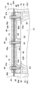
図7、図8に示すように、前部支持体50における環状枠部52の上横枠部分52Bには、燃料タンク20の前フランジ部23Aを載置支持する水平な載置支持面52bが形成されている。この載置支持面52bを備えた上横枠部分52Bの左右方向中間部の二箇所には、図6、図7、図10に示すように、上カバー40に対する取付けスペースを形成するための平面視略扁平U字状の凹部61が切欠き形成されている。
そのため、図5~図7に示すように、環状枠部52の上横枠部分52Bのうち、両凹部61で区画された左右方向両側部位と左右方向中央部位の各々が、燃料タンク20の前フランジ部23Aに対するタンク取付け部62に構成されている。各タンク取付け部62は、環状枠部52の上横枠部分52Bの他の部位よりも厚肉に構成され、各タンク取付け部62には、燃料タンク20の前フランジ部23Aを螺合固定するための第3ボルト69に対する第3ネジ孔63が形成されている。
図7、図8に示すように、前部支持体50における環状枠部52の上横枠部分52Bには、燃料タンク20の前フランジ部23Aを載置支持する水平な載置支持面52bが形成されている。この載置支持面52bを備えた上横枠部分52Bの左右方向中間部の二箇所には、図6、図7、図10に示すように、上カバー40に対する取付けスペースを形成するための平面視略扁平U字状の凹部61が切欠き形成されている。
そのため、図5~図7に示すように、環状枠部52の上横枠部分52Bのうち、両凹部61で区画された左右方向両側部位と左右方向中央部位の各々が、燃料タンク20の前フランジ部23Aに対するタンク取付け部62に構成されている。各タンク取付け部62は、環状枠部52の上横枠部分52Bの他の部位よりも厚肉に構成され、各タンク取付け部62には、燃料タンク20の前フランジ部23Aを螺合固定するための第3ボルト69に対する第3ネジ孔63が形成されている。
図7~図10に示すように、前部支持体50の載置支持面52bと燃料タンク20の前フランジ部23Aの下面との間には、載置支持面52bの輪郭形状に近い輪郭形状に形成されている下側防振ゴム65が介装されている。この下側防振ゴム65には、上横枠部分52Bの各第3ネジ孔63に対応する第3ボルト挿通孔65aと、上横枠部分52Bの各凹部61に対応する同一形状の第1凹部65bが形成されている。
燃料タンク20の前フランジ部23Aの上面には、図5、図7~図9に示すように、載置支持面52bの輪郭形状に近い輪郭形状にそれぞれ形成されている上側防振ゴム66と、金属製の押え板67が配設されている。上側防振ゴム66には、上横枠部分52Bの各第3ネジ孔63に対応する第4ボルト挿通孔66aと、上横枠部分52Bの各凹部61に対応する同一形状の第2凹部66bが形成されている。押え板67にも、上横枠部分52Bの各第3ネジ孔63に対応する第5ボルト挿通孔67aと、上横枠部分52Bの各凹部61に対応する同一形状の第3凹部67bが形成されている。
また、燃料タンク20の前フランジ部23Aには、図7、図8に示すように、上横枠部分52Bの各第3ネジ孔63に対応する第6ボルト挿通孔68が形成されている。
また、燃料タンク20の前フランジ部23Aには、図7、図8に示すように、上横枠部分52Bの各第3ネジ孔63に対応する第6ボルト挿通孔68が形成されている。
図7、図8に示すように、燃料タンク20の前フランジ部23Aにおける各第6ボルト挿通孔68の内面と各第3ボルト69の外面との間で、且つ、前部支持体50の上横枠部分52Bの上面と押え板67の下面との間には、金属製の筒状の位置決め用のカラー73が嵌合装着されている。各カラー73の外周面は8角形(8角形以外の多角形又は円形に形成してもよい)に形成されている。カラー73と接触又は近接する上側防振ゴム66の各第4ボルト挿通孔66a、前フランジ部23Aの各第6ボルト挿通孔68、下側防振ゴム65の各第3ボルト挿通孔65aも8角形に形成されている。
また、前部支持体50の上横枠部分52Bに形成されている第3ネジ孔63のうち、左右両外側端に位置する第3ネジ孔63の上部には、カラー73の下端部が嵌合する8角形の嵌合孔63aが形成されている。
また、前部支持体50の上横枠部分52Bに形成されている第3ネジ孔63のうち、左右両外側端に位置する第3ネジ孔63の上部には、カラー73の下端部が嵌合する8角形の嵌合孔63aが形成されている。
そして、燃料タンク20の前部を取付ける。その場合、先ず、図5、図7~図9に示すように、シリンダブロック2に固定されている前部支持体50の載置支持面52bに、下側防振ゴム65を介して燃料タンク20の前フランジ部23Aを載置する。さらに、燃料タンク20の前フランジ部23Aの上面に上側防振ゴム66を介して押え板67を当て付ける。この重合載置状態においては、燃料タンク20の前フランジ部23Aにおける各第6ボルト挿通孔68の内面と各第3ボルト69の外面との間で、且つ、前部支持体50の上横枠部分52Bの上面と押え板67の下面との間には、金属製の筒状の位置決め用のカラー73が嵌合装着されている。
また、図8に示すように、左右両外側端に位置するカラー73の下端部は、第3ネジ孔63の上部に形成されている嵌合孔63aに嵌合する。そして、左右中央に位置するカラー73の下端は、上横枠部分52Bの載置支持面52bに当接している。
上述の重合載置状態において、図7、図8に示すように、押え板67の各第5ボルト挿通孔67aに挿通された第3ボルト69を、上側防振ゴム66の各第4ボルト挿通孔66a、燃料タンク20の前フランジ部23Aの各第6ボルト挿通孔68、下側防振ゴム65の第3ボルト挿通孔65aを貫通して前部支持体50の上横枠部分52Bの第3ネジ孔63に螺合固定する。
また、図8に示すように、左右両外側端に位置するカラー73の下端部は、第3ネジ孔63の上部に形成されている嵌合孔63aに嵌合する。そして、左右中央に位置するカラー73の下端は、上横枠部分52Bの載置支持面52bに当接している。
上述の重合載置状態において、図7、図8に示すように、押え板67の各第5ボルト挿通孔67aに挿通された第3ボルト69を、上側防振ゴム66の各第4ボルト挿通孔66a、燃料タンク20の前フランジ部23Aの各第6ボルト挿通孔68、下側防振ゴム65の第3ボルト挿通孔65aを貫通して前部支持体50の上横枠部分52Bの第3ネジ孔63に螺合固定する。
上述のように、シリンダブロック2の上面2aと前側面2bとの二面に亘って強固に取付けられている前部支持体50の上横枠部分52Bに、燃料タンク20の前フランジ部23Aを載置する。さらに、燃料タンク20の前フランジ部23Aの上下両側に防振ゴム65,66を介在させた状態で締結する。そのため、燃料タンク20の前部を振動の少ない状態で取付けることができる。
しかも、燃料タンク20の前フランジ部23Aの各第6ボルト挿通孔68の内面と各第3ボルト69の外面との間で、且つ、前部支持体50の上横枠部分52Bの上面と押え板67の下面との間には、金属製の筒状の位置決め用のカラー73が嵌合装着されているので、燃料タンク20の前部を頑丈に取付けることができる。
さらに、左右両外側端に位置するカラー73は、燃料タンク20の前フランジ部23Aの第6ボルト挿通孔68に嵌合し、且つ、前部支持体50の上横枠部分52Bにおける第3ネジ孔63の上部に形成されている嵌合孔63aに嵌合している。そのため、燃料タンク20の前部における左右方向及び前後方向での取付け精度の向上を図ることができる。これにより、燃料タンク20の前部に近接配置される状態で同じく前部支持体50に取付けられる上カバー40、両前部サイドカバー7の前部との各隣接間における隙間を極力小さくして外観意匠の向上を図ることができる。
しかも、燃料タンク20の前フランジ部23Aの各第6ボルト挿通孔68の内面と各第3ボルト69の外面との間で、且つ、前部支持体50の上横枠部分52Bの上面と押え板67の下面との間には、金属製の筒状の位置決め用のカラー73が嵌合装着されているので、燃料タンク20の前部を頑丈に取付けることができる。
さらに、左右両外側端に位置するカラー73は、燃料タンク20の前フランジ部23Aの第6ボルト挿通孔68に嵌合し、且つ、前部支持体50の上横枠部分52Bにおける第3ネジ孔63の上部に形成されている嵌合孔63aに嵌合している。そのため、燃料タンク20の前部における左右方向及び前後方向での取付け精度の向上を図ることができる。これにより、燃料タンク20の前部に近接配置される状態で同じく前部支持体50に取付けられる上カバー40、両前部サイドカバー7の前部との各隣接間における隙間を極力小さくして外観意匠の向上を図ることができる。
次に、上カバー40の取付け構造について説明する。
上カバー40は、図4、図5、図7~図10に示すように、中央カバー部40Aと、左右の両傾斜カバー部40Bとからなる。中央カバー部40Aは、燃料タンク20のタンクカバー21の前端壁部21Aに対面する。両傾斜カバー部40Bは、当該中央カバー部40Aの左右方向両側に連続する状態でタンクカバー21の左右の傾斜壁部21Bに対面する。中央カバー部40Aの下端縁には、図7、図10に示すように、前部支持体50の上横枠部分52Bに形成されている両凹部61及び下側防振ゴム65の両第1凹部65bに対して前方側から係合可能な左右一対の取付け片40Cが折り曲げ形成されている。
上カバー40は、図4、図5、図7~図10に示すように、中央カバー部40Aと、左右の両傾斜カバー部40Bとからなる。中央カバー部40Aは、燃料タンク20のタンクカバー21の前端壁部21Aに対面する。両傾斜カバー部40Bは、当該中央カバー部40Aの左右方向両側に連続する状態でタンクカバー21の左右の傾斜壁部21Bに対面する。中央カバー部40Aの下端縁には、図7、図10に示すように、前部支持体50の上横枠部分52Bに形成されている両凹部61及び下側防振ゴム65の両第1凹部65bに対して前方側から係合可能な左右一対の取付け片40Cが折り曲げ形成されている。
上カバー40の両取付け片40Cは、図7、図9、図10に示すように、上横枠部分52Bの各凹部61及び下側防振ゴム65の各第1凹部65bに臨む燃料タンク20の前フランジ部23Aの下面に当接可能に構成されている。各取付け片40Cには、下方から挿入操作される第4ボルト41に対する第7ボルト挿通孔42が形成されている。
各取付け片40Cの外縁輪郭形状は、図7、図10に示すように、上横枠部分52Bの凹部61及び下側防振ゴム65の両第1凹部65b各内縁輪郭形状と同一又は僅かに小なる略相似形の平面視略扁平U字状の輪郭形状に形成されている。そのため、上カバー40が燃料タンク20の前フランジ部23Aに取付けられた状態では、上カバー40の各取付け片40Cの外縁が下側防振ゴム65の両第1凹部65bの各内面に当接又は近接する。よって、各取付け片40Cの外縁が、燃料タンク20の前フランジ部23Aに対する上カバー40の左右方向での移動を規制する位置決め部として機能する。これにより、位置決め精度の向上を図ることができるとともに、上カバー40の位置ずれを解消することができる。
さらに、図7、図10に示すように、前部支持体50の上横枠部分52Bの両凹部61と下側防振ゴム65の両第1凹部65bとが同一形状に形成されている。そのため、上横枠部分52Bの両凹部61の各内面と下側防振ゴム65の両第1凹部65bの各内面とが、前方側から係合操作される上カバー40の各取付け片40Cを所定係合位置に案内する係合案内面として機能する。しかも、この係合案内面は、上横枠部分52Bの厚みと下側防振ゴム65の厚みを合わせた上下方向に長い面となる。よって、上カバー40の組付け作業の容易化を図ることができる。
また、図5、図7、図9に示すように、燃料タンク20の前フランジ部23Aには、上カバー40の両取付け片40Cの第7ボルト挿通孔42に対応する部位に第8ボルト挿通孔43が形成されている。前フランジ部23Aの上面には、第8ボルト挿通孔43に対して下方から挿入された第4ボルト41が螺合するナット44が固着されている。
上カバー40の両傾斜カバー部40Bの後端部分には、図7に示すように、タンク本体22の側壁部22Cに固着されている第1ブラケット25(図5参照)に螺合固定される第1ネジ部材45に対するネジ挿通孔46が形成されている。
そして、上カバー40を取付ける。その場合、先ず、図7、図9、図10に示すように、中央カバー部40Aの下端縁の取付け片40Cを、前部支持体50の上横枠部分52Bに形成されている両凹部61及び下側防振ゴム65の両第1凹部65bに対して前方側から係入させる。このとき、図9、図10に示すように、上カバー40の各取付け片40Cの外縁は、上横枠部分52Bの凹部61の各内面及び下側防振ゴム65の両第1凹部65bの各内面に当接又は近接する。よって、燃料タンク20の前フランジ部23Aに対する上カバー40の左右方向での位置ずれが防止される。
次に、上カバー40の両取付け片40Cを、図9,図10に示すように、上横枠部分52Bの各凹部61及び下側防振ゴム65の各第1凹部65bに臨む燃料タンク20の前フランジ部23Aの下面に当接させる。この状態において、図7、図9、図10に示すように、上カバー40の各取付け片40Cの第7ボルト挿通孔42に対して第4ボルト41を下方から挿入する。そして、その第4ボルト41を、燃料タンク20の前フランジ部23Aの第8ボルト挿通孔43を通過して前フランジ部23Aの上面に固着されているナット44に螺合固定する。
また、図5、図7に示すように、上カバー40の両傾斜カバー部40Bの後端部分に形成されているネジ挿通孔46に第1ネジ部材45に挿通し、タンク本体22の側壁部22Cの第1ブラケット25に螺合固定する。
また、図5、図7に示すように、上カバー40の両傾斜カバー部40Bの後端部分に形成されているネジ挿通孔46に第1ネジ部材45に挿通し、タンク本体22の側壁部22Cの第1ブラケット25に螺合固定する。
上述のように、上カバー40の各取付け片40Cは、前フランジ部23Aの下面に当接するように構成されているため、上カバー40の下端縁は、燃料タンク20の前フランジ部23Aよりも下方に配置される。これにより、上カバー40が燃料タンク20の前フランジ部23Aに固定された状態では、燃料タンク20の溶接シーム部を上カバー40で体裁良く覆い隠すことができるとともに、シーム溶接部分の劣化を抑制することができる。
次に、ヘッドライト30の取付け構造について説明する。
ヘッドライト30は、図1~図4、図7に示すように、レンズ部31の周縁部分と光源29を備えたランプハウジング32の周縁部分とを水密状態に嵌合接合して構成されている。レンズ部31は、側面視において略「く」字状に屈曲する前面レンズ部分31Aと、当該前面レンズ部分31Aの左右方向両側から後方外方側に向けて延出される側面レンズ部分31Bとから構成されている。
ランプハウジング32は、光源29を収納する椀状の反射面構成部32Aと、当該反射面構成部32Aの左右方向両側からレンズ部31の両側面レンズ部分31Bに沿って後方外方側に延出される側面カバー部32Bとから構成されている。
ヘッドライト30は、図1~図4、図7に示すように、レンズ部31の周縁部分と光源29を備えたランプハウジング32の周縁部分とを水密状態に嵌合接合して構成されている。レンズ部31は、側面視において略「く」字状に屈曲する前面レンズ部分31Aと、当該前面レンズ部分31Aの左右方向両側から後方外方側に向けて延出される側面レンズ部分31Bとから構成されている。
ランプハウジング32は、光源29を収納する椀状の反射面構成部32Aと、当該反射面構成部32Aの左右方向両側からレンズ部31の両側面レンズ部分31Bに沿って後方外方側に延出される側面カバー部32Bとから構成されている。
そして、図7に示すように、ヘッドライト30のランプハウジング32の背面で、且つ、レンズ部31とランプハウジング32との嵌合外周縁部よりも内方側に偏位した下部側の左右方向の両側部には、後方側に水平に突出する位置決めピン33が設けられている。ランプハウジング32の背面で、且つ、レンズ部31とランプハウジング32との嵌合外周縁部よりも内方側に偏位した上部側の左右方向の両側部には、取付け部材34が後方に水平に延出されている。この取付け部材34は、前部支持体50の三つのタンク取付け部62のうち、左右方向の両側部に位置するタンク取付け部62の下面に当て付け可能である。
また、図4~図7に示すように、前部支持体50の環状枠部52のうち、下横枠部分52Aと左右の縦枠部分52Cとで形成される両角部の各々には、左右方向の外方下方に向かって延出されるアーム部70が一体形成されている。両アーム部70の中間部には、図6、図7に示すように、ランプハウジング32の両位置決めピン33が前後方向から係合する位置決め係合孔71が形成されている。
前部支持体50における左右両側部のタンク取付け部62には、図7に示すように、下方からネジ込み操作される第2ネジ部材35に対する第4ネジ孔72が形成されている。ランプハウジング32の両取付け部材34の先端部には、前部支持体50の両タンク取付け部62の第4ネジ孔72に螺合された第2ネジ部材35に対して前方から係合可能な後方開口のネジ挿通用切欠き34aが形成されている。
そして、図7に示すように、ランプハウジング32の両位置決めピン33と、両位置決めピン33が前後方向から係合する状態で前部支持体50の両アーム部70に形成された位置決め係合孔71とが設けられている。これら位置決めピン33と位置決め係合孔71とをもって、前部支持体50とヘッドライト30との位置決め部36が構成されている。
また、図7に示すように、ランプハウジング32の両取付け部材34と、前部支持体50の両タンク取付け部62に形成された第4ネジ孔72と、各取付け部材34のネジ挿通用切欠き34aを通過してタンク取付け部62の第4ネジ孔72に螺合固定される第2ネジ部材35とが設けられている。これら取付け部材34と第4ネジ孔72と第2ネジ部材35とをもって、前部支持体50とヘッドライト30との締結部37が構成されている。
このヘッドライト30用の位置決め部36及び締結部37は、ヘッドライト30のランプハウジング32の背面側にのみ設けられている。
また、図7に示すように、ランプハウジング32の両取付け部材34と、前部支持体50の両タンク取付け部62に形成された第4ネジ孔72と、各取付け部材34のネジ挿通用切欠き34aを通過してタンク取付け部62の第4ネジ孔72に螺合固定される第2ネジ部材35とが設けられている。これら取付け部材34と第4ネジ孔72と第2ネジ部材35とをもって、前部支持体50とヘッドライト30との締結部37が構成されている。
このヘッドライト30用の位置決め部36及び締結部37は、ヘッドライト30のランプハウジング32の背面側にのみ設けられている。
そのため、ヘッドライト30用の位置決め部36及び締結部37が、例えば、ランプハウジング32の背面と、レンズ部31とランプハウジング32との嵌合外周縁部よりも外方側の側面とに分散して設けられている。このような場合のように、ヘッドライト30の側面の形態が位置決め部36及び締結部37で制限されることがない。それ故に、ヘッドライト30の側面形態のデザイン上の制約が無くなり、ヘッドライト30をそれの側方に張り出した大形ランプ形状とすることも可能となる。
ヘッドライト30を前部支持体50に取付ける。その場合、第2ネジ部材35を先付けする第1の取付け方法と、第2ネジ部材35を後付けする第2の取付け方法が存在する。
第1の取付け方法では、両タンク取付け部62の第4ネジ孔72に第2ネジ部材35を先付けする。そして、ランプハウジング32の両位置決めピン33及び両取付け部材34のネジ挿通用切欠き34aを、前部支持体50の位置決め係合孔71及び第2ネジ部材35に対してそれぞれ前方側から係合させる。その後、第2ネジ部材35を本締めして固定する。
第2の取付け方法では、ランプハウジング32の両位置決めピン33を、前部支持体50の位置決め係合孔71に対して前方側から係合させる。その後、第2ネジ部材35を、下方から両取付け部材34のネジ挿通用切欠き34aを通過して両タンク取付け部62の第4ネジ孔72に締め付け固定する。
第1の取付け方法では、両タンク取付け部62の第4ネジ孔72に第2ネジ部材35を先付けする。そして、ランプハウジング32の両位置決めピン33及び両取付け部材34のネジ挿通用切欠き34aを、前部支持体50の位置決め係合孔71及び第2ネジ部材35に対してそれぞれ前方側から係合させる。その後、第2ネジ部材35を本締めして固定する。
第2の取付け方法では、ランプハウジング32の両位置決めピン33を、前部支持体50の位置決め係合孔71に対して前方側から係合させる。その後、第2ネジ部材35を、下方から両取付け部材34のネジ挿通用切欠き34aを通過して両タンク取付け部62の第4ネジ孔72に締め付け固定する。
ヘッドライト30の取付け作業は、前部支持体50の取付け作業、その後の燃料タンク20の取付け作業、その後の上カバー40の取付け作業を行った後に実行される。その作業において、ヘッドライト30の最上端位置であるレンズ部31の上端縁の高さ位置は、図9に示すように、上カバー40の各取付け片40Cの下面よりも下方位置に設定されている。そのため、仕組でヘッドライト30を組付ける際に上カバー40と接触することはない。
また、図1~図3に示すように、ヘッドライト30のレンズ部31の上端縁及び上カバー40の下端縁は共に水平方向に沿う一直線状に形成されている。これにより、ヘッドライト30のレンズ部31の上端縁と上カバー40の下端縁との間の隙間を見かけ上小さく見せることができる。
次に、両前部サイドカバー7の取付け構造について説明する。
各前部サイドカバー7の全周縁には、図1~図3、図10、図11に示すように、横形エンジン1の左右方向中央側である内方側に向かってフランジ80が折り曲げ形成されている。このカバーフランジ80は、上側フランジ部80Aと、屈曲フランジ部80Bと、前端フランジ部80Cと、下側フランジ部80Dと、後側フランジ部80Eとから構成されている。屈曲フランジ部80Bは、当該上側フランジ部80Aの前端に連続する状態でレンズ部31の側面レンズ部分31Bの「く」の字状(略横向きV字状)の外縁に沿うように構成されている。前端フランジ部80Cは、当該屈曲フランジ部80Bの前端から前方下方に延びるように構成されている。下側フランジ部80Dは、前端フランジ部80Cの下端から後方に延びるように構成されている。後側フランジ部80Eは、上側フランジ部80Aの後端と下側フランジ部80Dの後端とを繋ぐように構成されている。そのうち、後側フランジ部80Eには、後部サイドカバー9の前端部と重合状態で共締め固定される連結カバー部81が一体形成されている。
各前部サイドカバー7の全周縁には、図1~図3、図10、図11に示すように、横形エンジン1の左右方向中央側である内方側に向かってフランジ80が折り曲げ形成されている。このカバーフランジ80は、上側フランジ部80Aと、屈曲フランジ部80Bと、前端フランジ部80Cと、下側フランジ部80Dと、後側フランジ部80Eとから構成されている。屈曲フランジ部80Bは、当該上側フランジ部80Aの前端に連続する状態でレンズ部31の側面レンズ部分31Bの「く」の字状(略横向きV字状)の外縁に沿うように構成されている。前端フランジ部80Cは、当該屈曲フランジ部80Bの前端から前方下方に延びるように構成されている。下側フランジ部80Dは、前端フランジ部80Cの下端から後方に延びるように構成されている。後側フランジ部80Eは、上側フランジ部80Aの後端と下側フランジ部80Dの後端とを繋ぐように構成されている。そのうち、後側フランジ部80Eには、後部サイドカバー9の前端部と重合状態で共締め固定される連結カバー部81が一体形成されている。
両前部サイドカバー7のフランジ80のうち、レンズ部31の両側面レンズ部分31Bに対応する前部側領域のフランジ部の左右方向の幅(以下、フランジ幅と呼称する)は、換言すれば、屈曲フランジ部80Bの前半側の緩傾斜フランジ部分80Baから前端フランジ部80Cに至る前部側領域のフランジ幅となる。そのフランジ幅は、屈曲フランジ部80Bの後半側の急傾斜フランジ部分80Bbのフランジ幅よりも大で、且つ、前端側ほどフランジ幅が広くなるテーパー状に形成されている。
上述のように、両サイドカバー7のフランジ80のうち、ヘッドライト30のレンズ部31における左右の側面に対応する前部側領域のフランジ幅は、他の部位のフランジ幅よりも広幅に構成されている。よって、この広幅の分だけ、レンズ部31の左右の側面がサイドカバー7の外面から離間することになる。これにより、ヘッドライト30のレンズ部31への物理的な接触を低減することができ、ヘッドライト30の保護を図ることができる。しかも、広幅に構成されている領域でのサイドカバー7の剛性が向上することになる。よって、両サイドカバー7の強度も改善することができ、剛性が高いサイドカバー7の領域によりヘッドライト30の左右側面に外力が伝わることを低減することができる。
特に、屈曲フランジ部80Bの前半側の緩傾斜フランジ部分80Ba及び前端フランジ部80Cを、前端側ほどフランジ幅が広くなるテーパー状に形成することにより、ヘッドライト30のレンズ部31をより効果的に保護することができる。
特に、屈曲フランジ部80Bの前半側の緩傾斜フランジ部分80Ba及び前端フランジ部80Cを、前端側ほどフランジ幅が広くなるテーパー状に形成することにより、ヘッドライト30のレンズ部31をより効果的に保護することができる。
また、前部支持体50の両アーム部70の先端部は、図4、図5に示すように、両前部サイドカバー7の前部に対する取付け部82に構成されている。両取付け部82の各々には、図5~図7に示すように、前部サイドカバー7の前端部に形成された第9ボルト挿通孔(図示省略)から挿入される第5ボルト84に対する第5ネジ孔85が形成されている。
さらに、図1~図3、図5に示すように、各前部サイドカバー7の前後中間部に形成された第10ボルト挿通孔(図示省略)から挿入された第6ボルト87は、タンク本体22の各側壁部22Cに固着されている第2ブラケット26に螺合固定されている。
さらに、図1~図3、図5に示すように、各前部サイドカバー7の前後中間部に形成された第10ボルト挿通孔(図示省略)から挿入された第6ボルト87は、タンク本体22の各側壁部22Cに固着されている第2ブラケット26に螺合固定されている。
次に、燃料タンク20の後部及びカバー関係の取付け構造について説明する。
図4、図11に示すように、エンジン本体4のシリンダブロック2の上面2aで、且つ、燃料タンク20とラジエータ5との間には、左右方向に沿ってアルミダイキャスト製の後部支持体90が取付けられている。この後部支持体90は、板状基部92と、板状脚部93と、タンク取付け板部94と、カバー取付け板部95とを一体形成して構成されている。板状基部92は、シリンダブロック2の上面2aに複数の第7ボルト91で固定される。板状脚部93は、当該板状基部92から上方に延出される板状に構成されている。タンク取付け板部94は、当該板状脚部93の上端位置において燃料タンク20の後フランジ部23Bを載置支持する水平な載置支持面を備える。カバー取付け板部95は、板状脚部93の右側面から横外方に延出される板状に構成されている。
図4、図11に示すように、エンジン本体4のシリンダブロック2の上面2aで、且つ、燃料タンク20とラジエータ5との間には、左右方向に沿ってアルミダイキャスト製の後部支持体90が取付けられている。この後部支持体90は、板状基部92と、板状脚部93と、タンク取付け板部94と、カバー取付け板部95とを一体形成して構成されている。板状基部92は、シリンダブロック2の上面2aに複数の第7ボルト91で固定される。板状脚部93は、当該板状基部92から上方に延出される板状に構成されている。タンク取付け板部94は、当該板状脚部93の上端位置において燃料タンク20の後フランジ部23Bを載置支持する水平な載置支持面を備える。カバー取付け板部95は、板状脚部93の右側面から横外方に延出される板状に構成されている。
タンク取付け板部94の左右方向両側部には、図11に示すように、燃料タンク20の後フランジ部23Bを固定する厚肉の第1取付け部96が形成されている。横形エンジン1の幅方向の略中心位置に相当するタンク取付け板部94の左右方向中央部には、吊りボルト12を構成する連結ボルト12Bが取付けられる厚肉の第2取付け部97が形成されている。
この第2取付け部97に螺合固定される連結ボルト12Bは、第2取付け部97の上面から後部上面カバー8の上面までの長さを有する。この連結ボルト12Bの上端部にアイボルト12Aが螺合固定されている。
この第2取付け部97に螺合固定される連結ボルト12Bは、第2取付け部97の上面から後部上面カバー8の上面までの長さを有する。この連結ボルト12Bの上端部にアイボルト12Aが螺合固定されている。
タンク取付け板部94の載置支持面には、図11に示すように、第1防振ゴム100を介して燃料タンク20の後フランジ部23Bが載置されている。さらに、燃料タンク20の後フランジ部23Bの上面には、後部上面カバー8を取付けるための第3ブラケット110が第2防振ゴム101を介して載置されている。この載置状態において、第8ボルト102が、タンク取付け板部94の両第1取付け部96に対して上方から螺合固定される。その第8ボルト102により、燃料タンク20の後フランジ部23Bと第3ブラケット110とが、シリンダブロック2の上面2aに固定されている後部支持体90のタンク取付け板部94に共締め固定される。
図示は省略するが、燃料タンク20の前部の取付け構造と同様に、燃料タンク20の後フランジ部23Bのボルト挿通孔(図示省略)の内面と第8ボルト102の外面との間で、かつ、後部支持体90の第1取付け部96の上面と第3ブラケット110の下面との間には、金属製の筒状の位置決め用のカラーが嵌合装着されている。各カラーの外周面は8角形(8角形以外の多角形又は円形に形成してもよい)に形成されている。カラーと接触又は近接する第1防振ゴム100のボルト挿通孔(図示省略)、後フランジ部23Bのボルト挿通孔、第2防振ゴム101のボルト挿通孔(図示省略)も8角形に形成されている。
また、後部支持体90の第1取付け部96に形成されるネジ孔(図示省略)の上部には、カラーの下端部が嵌合する8角形の嵌合孔(図示省略)が形成されている。
また、後部支持体90の第1取付け部96に形成されるネジ孔(図示省略)の上部には、カラーの下端部が嵌合する8角形の嵌合孔(図示省略)が形成されている。
上述のように、シリンダブロック2の上面2aに強固に取付けられている後部支持体90の第1取付け部96に燃料タンク20の後フランジ部23Bを載置する。さらに、燃料タンク20の後フランジ部23Bの上下両側に防振ゴム100,101を介在させた状態で第3ブラケット110を締結する。そのため、燃料タンク20の後部を振動の少ない状態で取付けることができる。
しかも、燃料タンク20の後フランジ部23Bの各ボルト挿通孔の内面と各第8ボルト102の外面との間で、且つ、後部支持体90の第1取付け部96の上面と第3ブラケット110の下面との間には、金属製の筒状の位置決め用のカラー(図示省略)が嵌合装着されている。よって、燃料タンク20の後部を頑丈に取付けることができる。
さらに、両カラーは、燃料タンク20の後フランジ部23Bの各ボルト挿通孔(図示省略)に嵌合し、且つ、後部支持体90の第1取付け部96におけるネジ孔(図示省略)の上部に形成されている嵌合孔(図示省略)に嵌合している。そのため、燃料タンク20の後部における左右方向及び前後方向での取付け精度の向上を図ることができる。
これにより、燃料タンク20の後部に近接配置される後部上面カバー8、両前部サイドカバー7の後部、両後部サイドカバー9の前部との各隣接間における隙間を極力小さくして外観意匠の向上を図ることができる。
しかも、燃料タンク20の後フランジ部23Bの各ボルト挿通孔の内面と各第8ボルト102の外面との間で、且つ、後部支持体90の第1取付け部96の上面と第3ブラケット110の下面との間には、金属製の筒状の位置決め用のカラー(図示省略)が嵌合装着されている。よって、燃料タンク20の後部を頑丈に取付けることができる。
さらに、両カラーは、燃料タンク20の後フランジ部23Bの各ボルト挿通孔(図示省略)に嵌合し、且つ、後部支持体90の第1取付け部96におけるネジ孔(図示省略)の上部に形成されている嵌合孔(図示省略)に嵌合している。そのため、燃料タンク20の後部における左右方向及び前後方向での取付け精度の向上を図ることができる。
これにより、燃料タンク20の後部に近接配置される後部上面カバー8、両前部サイドカバー7の後部、両後部サイドカバー9の前部との各隣接間における隙間を極力小さくして外観意匠の向上を図ることができる。
尚、後部上面カバー8の後部は、図1~図3に示すように、ラジエータ5側に固定される取付け機材(図示せず)に第9ボルト113で固定されている。
前記第3ブラケット110は、図11に示すように、前後方向視において逆向きの門の字状(略逆U字状)に折り曲げ形成されたブラケット本体111を備える。当該ブラケット本体111の両上端部には、後部上面カバー8の前部を第9ボルト113で固定するための取付け片112が左右方向の内方側に折り曲げ形成されている。
後部支持体90のカバー取付け板部95の右端側の上下両側部には、図10に示すように、厚肉の取付け部98が形成されている。両取付け部98には、前部サイドカバー7の連結カバー部81を取付けるための第4ブラケット120が第10ボルト123で固定されている。
第4ブラケット120は、図11に示すように、前後方向視において横向きの門の字状(略逆U字状)に折り曲げ形成されたブラケット本体121を備える。当該ブラケット本体121の両先端部には、前部サイドカバー7の連結カバー部81の上下両端部を第11ボルト131で固定するための取付け片122が上方側に折り曲げ形成されている。
第4ブラケット120は、図11に示すように、前後方向視において横向きの門の字状(略逆U字状)に折り曲げ形成されたブラケット本体121を備える。当該ブラケット本体121の両先端部には、前部サイドカバー7の連結カバー部81の上下両端部を第11ボルト131で固定するための取付け片122が上方側に折り曲げ形成されている。
また、図3、図11に示すように、右側に位置する前部サイドカバー7の連結カバー部81と同じく右側に位置する後部サイドカバー9の前部とが重ね合わされた状態で配置されている。これら両者の重合部分がノブ付きボルト132で固定されている。
後部支持体90の板状脚部93は、図4に示すように、燃料タンク20のタンク本体22における後壁部22Bの傾斜後壁部分22bに沿う傾斜姿勢に構成されている。板状脚部93の下半部側が後壁部22Bの傾斜後壁部分22bの直下位置に入り込み配置されている。
上述のように、板状脚部93の下半部側を、燃料タンク20の後部下方に入り込み配置する。そのことにより、燃料タンク20とそれの後方に配置されるラジエータ5との間の空間、詳しくは、後部支持体90の板状脚部93とラジエータ5との対向面間に形成される空間が拡大形成される。そのため、この拡大された空間を、図4の仮想線で示すように、ラジエータ5に接続されるサブタンク140が配置可能な取付け空間141に形成してある。
上述のように、板状脚部93の下半部側を、燃料タンク20の後部下方に入り込み配置する。そのことにより、燃料タンク20とそれの後方に配置されるラジエータ5との間の空間、詳しくは、後部支持体90の板状脚部93とラジエータ5との対向面間に形成される空間が拡大形成される。そのため、この拡大された空間を、図4の仮想線で示すように、ラジエータ5に接続されるサブタンク140が配置可能な取付け空間141に形成してある。
サブタンク140は、ラジエータ5と配管で接続され、ラジエータ5内の冷却水のオーバーフロー分を貯留するように構成されている。ラジエータ5内の冷却水が熱膨張により増加すると、ラジエータ5内の冷却水がサブタンク140内に流入する。逆に、ラジエータ5内の冷却水が減少すると、サブタンク140内の冷却水がラジエータ5に戻される。これにより、ラジエータ5内の冷却水が所定量に維持される。
上述の構成により、ラジエータ5に接続されるサブタンク140を配置する必要が生じたとき、燃料タンク20とラジエータ5との間に予め確保されている取付け空間141を使用して容易に取付けることができる。
なお、後部支持体90の板状脚部93に、サブタンク140の一部が入り込み配置可能な凹部又は開口が形成されている場合には、サブタンク140を一層容易に取付けことができる。
また、サブタンク140を後部支持体90に取付けてもよい。
なお、後部支持体90の板状脚部93に、サブタンク140の一部が入り込み配置可能な凹部又は開口が形成されている場合には、サブタンク140を一層容易に取付けことができる。
また、サブタンク140を後部支持体90に取付けてもよい。
さらに、左側に位置する前部サイドカバー7の連結カバー部81は、図1、図2、図11に示すように、同じ左側に位置する後部サイドカバー9の前部に重ね合わされた状態で配置されている。これら両者の重合部分がラジエータ5側又はシリンダブロック2側に固定される取付け機材(図示せず)に第12ボルト150で固定されている。左側に位置する後部サイドカバー9の後部も、ラジエータ5側又はシリンダブロック2側に固定される取付け機材(図示せず)に第13ボルト151で固定されている。
〔その他の実施形態〕
(1)上述の実施形態では、両前部サイドカバー7のフランジ80のうち、屈曲フランジ部80Bの前半側の緩傾斜フランジ部分80Baから前端フランジ部80Cに至る前部側領域のフランジ幅を、他の部位のフランジ幅よりも広幅で、且つ、前端側ほどフランジ幅が広くなるテーパー状に形成したが、この構成に限定されない。例えば、屈曲フランジ部80Bの後端から前端フランジ部80Cに至る前半側領域のフランジ幅を、他の部位のフランジ幅よりも広幅に構成してもよい。さらに、前端側に位置する前端フランジ部80Cのフランジ幅のみを、他の部位のフランジ幅よりも広幅に構成してもよい。
また、他の部位よりも広幅に構成される領域のフランジ幅を平行に構成してもよい。
(1)上述の実施形態では、両前部サイドカバー7のフランジ80のうち、屈曲フランジ部80Bの前半側の緩傾斜フランジ部分80Baから前端フランジ部80Cに至る前部側領域のフランジ幅を、他の部位のフランジ幅よりも広幅で、且つ、前端側ほどフランジ幅が広くなるテーパー状に形成したが、この構成に限定されない。例えば、屈曲フランジ部80Bの後端から前端フランジ部80Cに至る前半側領域のフランジ幅を、他の部位のフランジ幅よりも広幅に構成してもよい。さらに、前端側に位置する前端フランジ部80Cのフランジ幅のみを、他の部位のフランジ幅よりも広幅に構成してもよい。
また、他の部位よりも広幅に構成される領域のフランジ幅を平行に構成してもよい。
(2)上述の実施形態では、シリンダブロック2の上面2aと前側面2bとの二面に亘って前部支持体50を固定したが、この前部支持体50を、シリンダブロック2の上面2aと左側面又は右側面との二面に亘って固定してもよい。
また、前部支持体50を、シリンダブロック2の上面2aと二つの側面との三面に亘って固定してもよい。さらに、前部支持体50を、シリンダブロック2の上面2aと三つの側面との四面に亘って固定してもよい。
また、前部支持体50を、シリンダブロック2の上面2aと二つの側面との三面に亘って固定してもよい。さらに、前部支持体50を、シリンダブロック2の上面2aと三つの側面との四面に亘って固定してもよい。
(3)上述の実施形態では、シリンダブロック2の上面2aに後部支持体90を固定したが、この後部支持体90をシリンダブロック2の上面2aと側面との少なくとも二面に亘って固定してもよい。
本発明は、エンジン本体の上部に燃料タンクが配設され、前記燃料タンクの前部側にはヘッドライトが配設され、前記燃料タンクの前部と前記ヘッドライトとの間を覆う上カバーが配設されているエンジンに適用できる。
2 シリンダブロック
4 エンジン本体
7 サイドカバー(前部サイドカバー)
20 燃料タンク
30 ヘッドライト
40 上カバー
50 前部支持体
65b 凹部(第1凹部)
90 後部支持体
98 取付け部
140 サブタンク
141 取付け空間
4 エンジン本体
7 サイドカバー(前部サイドカバー)
20 燃料タンク
30 ヘッドライト
40 上カバー
50 前部支持体
65b 凹部(第1凹部)
90 後部支持体
98 取付け部
140 サブタンク
141 取付け空間
Claims (5)
- エンジン本体の上部に燃料タンクが配設され、前記燃料タンクの前部側にはヘッドライトが配設され、前記燃料タンクの前部と前記ヘッドライトとの間を覆う上カバーが配設されているエンジンであって、
前記上カバーが前記燃料タンクの接合フランジの前部に直接締結されているエンジン。 - 前記ヘッドライトは、前記上カバーと前記燃料タンクの左右両側に配置されるサイドカバーの前部とで囲まれた下方開口の部位に配設されている請求項1記載のエンジン。
- 前記燃料タンクの前記接合フランジの前部は、前記エンジン本体のシリンダブロックに固定された前部支持体に固定され、前記前部支持体のタンク取付け部位側には、前記上カバーの取付け片が係合する凹部が形成されている請求項1又は2記載のエンジン。
- 前記上カバーの下端縁は、前記燃料タンクの前記接合フランジの前部よりも下方に配置されている請求項1~3のいずれか1項に記載のエンジン。
- 前記両サイドカバーの左右方向の幅うち、前記ヘッドライトのレンズ部の左右の側面に対応する領域の幅が、少なくとも前端側において広幅に構成されている請求項2記載のエンジン。
Applications Claiming Priority (2)
| Application Number | Priority Date | Filing Date | Title |
|---|---|---|---|
| JP2017052702A JP6655573B2 (ja) | 2017-03-17 | 2017-03-17 | エンジン |
| JP2017-052702 | 2017-03-17 |
Publications (1)
| Publication Number | Publication Date |
|---|---|
| WO2018168254A1 true WO2018168254A1 (ja) | 2018-09-20 |
Family
ID=63523034
Family Applications (1)
| Application Number | Title | Priority Date | Filing Date |
|---|---|---|---|
| PCT/JP2018/003747 Ceased WO2018168254A1 (ja) | 2017-03-17 | 2018-02-05 | エンジン |
Country Status (2)
| Country | Link |
|---|---|
| JP (1) | JP6655573B2 (ja) |
| WO (1) | WO2018168254A1 (ja) |
Families Citing this family (1)
| Publication number | Priority date | Publication date | Assignee | Title |
|---|---|---|---|---|
| EP3842395A4 (en) | 2018-08-22 | 2022-04-20 | Sumitomo Electric Industries, Ltd. | OPTICAL FIBER |
Citations (5)
| Publication number | Priority date | Publication date | Assignee | Title |
|---|---|---|---|---|
| JPS53133915U (ja) * | 1977-03-31 | 1978-10-24 | ||
| JPS55104727U (ja) * | 1979-01-17 | 1980-07-22 | ||
| JPS6169476U (ja) * | 1984-10-12 | 1986-05-12 | ||
| JP2002347452A (ja) * | 2001-05-25 | 2002-12-04 | Kubota Corp | 燃料タンクのカバー装置 |
| JP2010055851A (ja) * | 2008-08-27 | 2010-03-11 | Kubota Corp | ヘッドランプと燃料タンクの支持構造 |
Family Cites Families (2)
| Publication number | Priority date | Publication date | Assignee | Title |
|---|---|---|---|---|
| JPS60124348U (ja) * | 1984-01-31 | 1985-08-22 | ヤンマーディーゼル株式会社 | 横形エンジンのヘツドランプ取付構造 |
| JP5659105B2 (ja) * | 2011-08-29 | 2015-01-28 | 株式会社クボタ | ヘッドランプカバーの支持構造 |
-
2017
- 2017-03-17 JP JP2017052702A patent/JP6655573B2/ja active Active
-
2018
- 2018-02-05 WO PCT/JP2018/003747 patent/WO2018168254A1/ja not_active Ceased
Patent Citations (5)
| Publication number | Priority date | Publication date | Assignee | Title |
|---|---|---|---|---|
| JPS53133915U (ja) * | 1977-03-31 | 1978-10-24 | ||
| JPS55104727U (ja) * | 1979-01-17 | 1980-07-22 | ||
| JPS6169476U (ja) * | 1984-10-12 | 1986-05-12 | ||
| JP2002347452A (ja) * | 2001-05-25 | 2002-12-04 | Kubota Corp | 燃料タンクのカバー装置 |
| JP2010055851A (ja) * | 2008-08-27 | 2010-03-11 | Kubota Corp | ヘッドランプと燃料タンクの支持構造 |
Also Published As
| Publication number | Publication date |
|---|---|
| JP2018155181A (ja) | 2018-10-04 |
| JP6655573B2 (ja) | 2020-02-26 |
Similar Documents
| Publication | Publication Date | Title |
|---|---|---|
| US8141670B2 (en) | Radiator attachment structure for saddle-ride type vehicle | |
| JP3982458B2 (ja) | エンジンの保護カバー | |
| JP5827595B2 (ja) | 鞍乗型車両のマフラー装置 | |
| US8807510B2 (en) | Mirror device for a vehicle | |
| JP5863728B2 (ja) | 部材の締結構造 | |
| US20150090512A1 (en) | Fuel tank and pump assembly, and motorcycle including same | |
| JP5208786B2 (ja) | 横型エンジン | |
| JP6655573B2 (ja) | エンジン | |
| JP2018138772A (ja) | 燃料供給管の保護構造 | |
| JP6718402B2 (ja) | エンジン | |
| JP2004044394A (ja) | 連結部材の取り付け構造 | |
| JP5386428B2 (ja) | 燃料ポンプの支持構造 | |
| JP6657632B2 (ja) | パワーユニットの支持構造 | |
| JP7658936B2 (ja) | エンジン | |
| JP4412003B2 (ja) | エンジンカバーの取付構造 | |
| JP3663900B2 (ja) | 自動二輪車のエンジン懸架装置 | |
| JP2003083163A (ja) | V型内燃機関のマウントブラケット取付構造 | |
| JP2006291807A (ja) | エンジン及び車両 | |
| JP2016176441A (ja) | 内燃機関 | |
| JP5775771B2 (ja) | エンジン | |
| JP7338672B2 (ja) | 配管取付構造およびブラケット | |
| JP6766020B2 (ja) | 保護部材取付構造 | |
| JP4735846B2 (ja) | オイルパン構造 | |
| JP2004299635A (ja) | ボンネットの開口孔部構造 | |
| CN110017204B (zh) | 端盖的安装结构 |
Legal Events
| Date | Code | Title | Description |
|---|---|---|---|
| 121 | Ep: the epo has been informed by wipo that ep was designated in this application |
Ref document number: 18766706 Country of ref document: EP Kind code of ref document: A1 |
|
| DPE1 | Request for preliminary examination filed after expiration of 19th month from priority date (pct application filed from 20040101) | ||
| NENP | Non-entry into the national phase |
Ref country code: DE |
|
| 122 | Ep: pct application non-entry in european phase |
Ref document number: 18766706 Country of ref document: EP Kind code of ref document: A1 |