WO2018163735A1 - 検出装置、パワーコンディショナ、検出方法、および検出プログラム - Google Patents
検出装置、パワーコンディショナ、検出方法、および検出プログラム Download PDFInfo
- Publication number
- WO2018163735A1 WO2018163735A1 PCT/JP2018/005116 JP2018005116W WO2018163735A1 WO 2018163735 A1 WO2018163735 A1 WO 2018163735A1 JP 2018005116 W JP2018005116 W JP 2018005116W WO 2018163735 A1 WO2018163735 A1 WO 2018163735A1
- Authority
- WO
- WIPO (PCT)
- Prior art keywords
- period
- time difference
- parameter
- frequency
- deviation
- Prior art date
- Legal status (The legal status is an assumption and is not a legal conclusion. Google has not performed a legal analysis and makes no representation as to the accuracy of the status listed.)
- Ceased
Links
Images





Classifications
-
- H—ELECTRICITY
- H02—GENERATION; CONVERSION OR DISTRIBUTION OF ELECTRIC POWER
- H02J—ELECTRIC POWER NETWORKS; CIRCUIT ARRANGEMENTS OR SYSTEMS FOR SUPPLYING OR DISTRIBUTING ELECTRIC POWER; SYSTEMS FOR STORING ELECTRIC ENERGY
- H02J3/00—Circuit arrangements for AC mains or AC distribution networks
- H02J3/38—Arrangements for feeding a single network from two or more generators or sources in parallel; Arrangements for feeding already energised networks from additional generators or sources in parallel
- H02J3/381—Dispersed generators
-
- H—ELECTRICITY
- H02—GENERATION; CONVERSION OR DISTRIBUTION OF ELECTRIC POWER
- H02J—ELECTRIC POWER NETWORKS; CIRCUIT ARRANGEMENTS OR SYSTEMS FOR SUPPLYING OR DISTRIBUTING ELECTRIC POWER; SYSTEMS FOR STORING ELECTRIC ENERGY
- H02J3/00—Circuit arrangements for AC mains or AC distribution networks
- H02J3/001—Arrangements for handling faults or abnormalities, e.g. emergencies or contingencies
- H02J3/0014—Arrangements for handling faults or abnormalities, e.g. emergencies or contingencies for preventing or reducing power oscillations in networks
- H02J3/00142—Oscillations concerning frequency
-
- H—ELECTRICITY
- H02—GENERATION; CONVERSION OR DISTRIBUTION OF ELECTRIC POWER
- H02J—ELECTRIC POWER NETWORKS; CIRCUIT ARRANGEMENTS OR SYSTEMS FOR SUPPLYING OR DISTRIBUTING ELECTRIC POWER; SYSTEMS FOR STORING ELECTRIC ENERGY
- H02J3/00—Circuit arrangements for AC mains or AC distribution networks
- H02J3/002—Flicker reduction, e.g. compensation of flicker introduced by non-linear load
-
- H—ELECTRICITY
- H02—GENERATION; CONVERSION OR DISTRIBUTION OF ELECTRIC POWER
- H02J—ELECTRIC POWER NETWORKS; CIRCUIT ARRANGEMENTS OR SYSTEMS FOR SUPPLYING OR DISTRIBUTING ELECTRIC POWER; SYSTEMS FOR STORING ELECTRIC ENERGY
- H02J3/00—Circuit arrangements for AC mains or AC distribution networks
- H02J3/007—Arrangements for selectively connecting one or more loads to one or more power sources or power lines
-
- H—ELECTRICITY
- H02—GENERATION; CONVERSION OR DISTRIBUTION OF ELECTRIC POWER
- H02J—ELECTRIC POWER NETWORKS; CIRCUIT ARRANGEMENTS OR SYSTEMS FOR SUPPLYING OR DISTRIBUTING ELECTRIC POWER; SYSTEMS FOR STORING ELECTRIC ENERGY
- H02J3/00—Circuit arrangements for AC mains or AC distribution networks
- H02J3/38—Arrangements for feeding a single network from two or more generators or sources in parallel; Arrangements for feeding already energised networks from additional generators or sources in parallel
-
- H—ELECTRICITY
- H02—GENERATION; CONVERSION OR DISTRIBUTION OF ELECTRIC POWER
- H02J—ELECTRIC POWER NETWORKS; CIRCUIT ARRANGEMENTS OR SYSTEMS FOR SUPPLYING OR DISTRIBUTING ELECTRIC POWER; SYSTEMS FOR STORING ELECTRIC ENERGY
- H02J2101/00—Supply or distribution of decentralised, dispersed or local electric power generation
- H02J2101/20—Dispersed power generation using renewable energy sources
- H02J2101/22—Solar energy
- H02J2101/24—Photovoltaics
-
- H—ELECTRICITY
- H02—GENERATION; CONVERSION OR DISTRIBUTION OF ELECTRIC POWER
- H02J—ELECTRIC POWER NETWORKS; CIRCUIT ARRANGEMENTS OR SYSTEMS FOR SUPPLYING OR DISTRIBUTING ELECTRIC POWER; SYSTEMS FOR STORING ELECTRIC ENERGY
- H02J3/00—Circuit arrangements for AC mains or AC distribution networks
- H02J3/38—Arrangements for feeding a single network from two or more generators or sources in parallel; Arrangements for feeding already energised networks from additional generators or sources in parallel
- H02J3/388—Arrangements for the handling of islanding, e.g. for disconnection or for avoiding the disconnection of power
-
- Y—GENERAL TAGGING OF NEW TECHNOLOGICAL DEVELOPMENTS; GENERAL TAGGING OF CROSS-SECTIONAL TECHNOLOGIES SPANNING OVER SEVERAL SECTIONS OF THE IPC; TECHNICAL SUBJECTS COVERED BY FORMER USPC CROSS-REFERENCE ART COLLECTIONS [XRACs] AND DIGESTS
- Y02—TECHNOLOGIES OR APPLICATIONS FOR MITIGATION OR ADAPTATION AGAINST CLIMATE CHANGE
- Y02E—REDUCTION OF GREENHOUSE GAS [GHG] EMISSIONS, RELATED TO ENERGY GENERATION, TRANSMISSION OR DISTRIBUTION
- Y02E10/00—Energy generation through renewable energy sources
- Y02E10/50—Photovoltaic [PV] energy
- Y02E10/56—Power conversion systems, e.g. maximum power point trackers
Definitions
- the present invention relates to a detection device, a power conditioner, a detection method, and a detection program.
- Patent Documents 1 and 2 Japanese Patent Application Laid-Open No. 2016-82789
- Patent Document 2 Japanese Patent Application Laid-Open No. 2016-131441
- the isolated operation detection system is required to operate properly in conjunction with the power system having various characteristics.
- a detection device in a first aspect of the invention, may include a frequency parameter calculation unit that calculates a frequency parameter corresponding to the frequency of the power supplied from the power source.
- the detection apparatus may include a deviation parameter calculation unit that calculates a deviation parameter according to the frequency deviation based on the frequency parameter in the first period and the frequency parameter in the second period that is earlier than the first period.
- the detection device may include an isolated operation detection unit that detects whether or not the power supply is operating independently based on the deviation parameter.
- the detection apparatus may include a time difference changing unit that changes a time difference between the first period and the second period.
- the detection device may include a flicker detection unit that detects whether or not flicker is generated in the power supplied from the power source.
- the time difference changing unit may change the time difference between the first period and the second period in response to detection of flicker.
- the time difference changing unit is configured to detect that the flicker is further detected.
- the time difference between the first period and the second period may be changed to a third time difference different from the first time difference and the second time difference.
- the time difference changing unit may change the time difference between the first period and the second period in a predetermined order from a plurality of predetermined time differences until no flicker is detected.
- the flicker detection unit may calculate a flicker cycle parameter corresponding to the flicker cycle.
- the time difference changing unit may change the time difference between the first period and the second period to a value based on the flicker cycle parameter.
- the detection apparatus may further include a period changing unit that changes the length of the second period.
- the period changing unit may change the length of the second period in response to detection of flicker.
- the period changing unit may calculate the frequency parameter in the second period by thinning out the frequency parameter sampled during the second period.
- the deviation parameter calculation unit may calculate a deviation parameter corresponding to a case where the time difference between the first period and the second period is each of a plurality of predetermined time differences.
- the time difference changing unit may preferentially select a plurality of deviation parameters corresponding to a plurality of time differences with a smaller fluctuation amount.
- the time difference changing unit may change the time difference between the first period and the second period to a time difference specified by an instruction received from the device of the power supplier.
- the deviation parameter calculation unit may calculate the deviation parameter based on a value obtained by low-pass filtering the frequency parameter of a plurality of periods in the second period.
- a power conditioner provided with the power converter which converts the electric power from a distributed power supply into the alternating current according to a system power supply, and said detection apparatus is provided.
- a detection method may include calculating a frequency parameter corresponding to the frequency of power supplied from the power source.
- the detection method may include calculating a deviation parameter corresponding to the frequency deviation based on the frequency parameter in the first period and the frequency parameter in the second period that is earlier than the first period.
- the detection method may include detecting whether the power source is operating independently based on the deviation parameter.
- the detection method may include changing a time difference between the first period and the second period.
- a detection program executed by the detection device may cause the detection device to function as a frequency parameter calculation unit that calculates a frequency parameter corresponding to the frequency of power supplied from the power source.
- the detection program causes the detection device to function as a deviation parameter calculation unit that calculates a deviation parameter according to the frequency deviation based on the frequency parameter in the first period and the frequency parameter in the second period that is earlier than the first period. May be.
- the detection program may cause the detection device to function as an isolated operation detection unit that detects whether the power supply is operated independently based on the deviation parameter.
- the detected woman gram may function as a time difference changing unit that changes the time difference between the first period and the second period.
- the structure of the grid connection system 1 which concerns on this embodiment is shown.
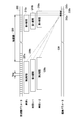
- An example of the timing of deviation parameter calculation according to the present embodiment is shown.
- An example of the relationship between the deviation parameter which concerns on this embodiment, and injection reactive electric energy is shown.
- An example of a situation where flicker occurs in the grid interconnection system 1 is shown.
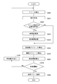
- movement flow of the power conditioner 30 which concerns on this embodiment is shown.
- the example of the period change by the period change part 94 is shown.
- 2 shows an exemplary configuration of a computer 2200 according to the present embodiment.
- FIG. 1 shows a configuration of a grid interconnection system 1 according to the present embodiment.
- the grid interconnection system 1 includes a grid power supply 10 included in a power system provided by an electric power supplier, a distributed power supply 20 such as a solar power generation system, a wind power generation system, and a fuel cell power generation system, a grid power supply 10 and a distributed power supply.
- a power conditioner 30 that is provided between the power supply 20 and converts the power from the distributed power supply 20 and supplies the power to the system power supply 10. Since the power supply from the system power supply 10 is cut off due to an accidental power outage, planned power outage, maintenance power outage or the like of the power system, the power conditioner 30 is disconnected from the power system and is in a single operation state. Detect that.
- the power conditioner 30 disconnects between the distributed power supply 20 side and the system power supply 10 side in response to detection of an isolated operation. Thereby, the power conditioner 30 can ensure the safety
- the power conditioner 30 includes a power conversion unit 40, an interconnection relay 50, and a detection device 60.
- the power conversion unit 40 includes an inverter 42 and an inverter control unit 44, and converts power from the distributed power supply 20 into alternating current corresponding to the system power supply 10.
- the inverter 42 converts the DC power or AC power from the distributed power supply 20 into AC power suitable for the power system and outputs it.
- the inverter control unit 44 controls the inverter control unit 44 so that the voltage, frequency, and phase of the AC power output from the inverter 42 match the power on the power system side.
- the interconnection relay 50 is a switch provided between the power conversion unit 40 and the system power supply 10 side.
- the interconnection relay 50 is connected or disconnected between the power conversion unit 40 and the system power supply 10 side under the control of the detection device 60. Thereby, the interconnection relay 50 switches whether the power conversion unit 40 on the distributed power supply 20 side is connected to the system power supply 10 side to link the system power supply 10 with the power system.
- the power conditioner 30 which concerns on this embodiment is set as the structure which incorporates the interconnection relay 50, it may replace with this and the structure which the interconnection relay 50 exists in the exterior of the power conditioner 30 may be taken. .
- Detecting device 60 detects that system power supply 10 is in a single operation state, and switches interconnection relay 50 to a disconnected state.
- the detection device 60 is a control computer including a CPU such as a microcontroller, and functions as the following units by executing a detection program. Instead of this, the detection device 60 may be realized by a dedicated circuit or a programmable circuit.
- the detection device 60 according to the present embodiment includes a frequency parameter calculation unit 65, a deviation parameter calculation unit 70, an isolated operation detection unit 75, a reactive power injection unit 80, a flicker detection unit 85, a communication unit 90, and a time difference.
- a change unit 92 and a period change unit 94 are included.
- the frequency parameter calculation unit 65 calculates a frequency parameter corresponding to the power supplied from the distributed power supply 20, that is, the frequency of the power supply power flowing in the power supply path between the interconnection relay 50 and the system power supply 10 in the present embodiment, for example.
- the frequency parameter calculation unit 65 detects the voltage of the power supply system path between the interconnection relay 50 and the system power supply 10 and calculates the frequency of the power supply power as an example of the frequency parameter from the change in voltage. Instead of this, the frequency parameter calculation unit 65 may detect the current flowing through the wiring and calculate the frequency parameter.
- the detection device 60 can use a period instead of using a frequency as a frequency parameter.
- the period is nothing but the reciprocal of the frequency
- the frequency parameter may be a value that changes according to the frequency or period, not the frequency or period itself.
- the deviation parameter calculation unit 70 calculates a deviation parameter corresponding to the frequency deviation based on the frequency parameter in a certain period (first period) and the frequency parameter in the second period that is earlier than the first period.
- the deviation parameter calculation unit 70 receives a sequence of frequency parameters output from the frequency parameter calculation unit 65, and represents representative values of a plurality of frequency parameters in a first period of a predetermined time length corresponding to the current period. And representative values of a plurality of frequency parameters in a second period having a predetermined time length corresponding to the past period.
- the representative values of the first period and the second period may be moving average values of the frequency parameters of the first period and the second period.
- the deviation parameter calculation unit 70 calculates the deviation of the representative value of the frequency parameter in the first period and the second period, that is, the representative value of the frequency parameter in the second period from the representative value of the frequency parameter in the first period, for example.
- a deviation parameter corresponding to the subtracted frequency deviation is calculated.
- the deviation parameter may be a periodic deviation or a value that changes in accordance with these.
- the isolated operation detection unit 75 detects whether or not the power supply is operating independently based on the deviation parameter output by the deviation parameter calculation unit 70. As an example, when the change in the deviation parameter more than the reference is detected, the isolated operation detection unit 75 is in a state where the power supply from the system power supply 10 is cut off and the distributed power supply 20 supplies power supply alone. to decide.
- the reactive power injection unit 80 injects reactive power according to the deviation parameter output from the isolated operation detection unit 75 into the power supply path.
- the detection device 60 employs an active isolated operation detection method as an example, injects reactive power into the power supply path between the power conversion unit 40 and the system power supply 10, and is invalid in the case of isolated operation.
- An isolated operation is detected by utilizing the fact that the frequency of the power supply power fluctuates greatly due to the influence of power injection. Instead, the detection device 60 detects a change in the frequency parameter over the reference range that occurs when the distributed power source 20 shifts from the linked state to the single operation state without injecting reactive power. May be taken.
- the detection device 60 may not include the reactive power injection unit 80.
- the flicker detection unit 85 detects whether or not flicker is generated in the power supply power flowing in the wiring between the interconnection relay 50 and the system power supply 10.
- Flicker is a phenomenon in which the voltage of the power supply path is excited by the reactive power injection by the reactive power injection unit 80, and a voltage fluctuation exceeding the flicker standard defined in advance periodically occurs in the power supply path.
- the periodic voltage fluctuation is not a change in the instantaneous voltage at the AC frequency in the AC voltage, but the maximum voltage (or effective voltage or average voltage) mainly in a cycle longer than the AC frequency (as an example, several Hz). ) Fluctuations.
- the communication unit 90 communicates with a device of an electric power company through a dedicated or general-purpose network, and receives various commands for the detection device 60 from the electric power company.
- the time difference changing unit 92 changes the time difference between the first period and the second period used when the deviation parameter calculating unit 70 calculates the deviation parameter.
- the time difference between the first period and the second period is defined as the time difference from the end timing of the second period to the end timing of the first period.
- the time difference between the first period and the second period may be a time difference from the end timing of the second period to the start timing of the first period.
- the period changing unit 94 changes the second period used when the deviation parameter calculating unit 70 calculates the deviation parameter. For example, the period changing unit 94 changes the length of the second period, whether to thin out the frequency parameter samples in the second period, and / or the calculation method of the frequency parameter in the second period.
- the time difference changing unit 92 and the period changing unit 94 may make these changes in response to a command from the electric power supplier, may make these changes in response to the detection of flicker, and other conditions. These changes may be made based on.
- the calculation method by which the deviation parameter calculation unit 70 calculates the deviation parameter can be changed according to a command from the electric power supplier and / or the detection of flicker. it can.
- the power conditioner 30 can appropriately detect the isolated operation by linking the distributed power source 20 to the power system having various characteristics.
- FIG. 2 shows an example of the deviation parameter calculation timing according to this embodiment.
- the frequency parameter calculation unit 65 outputs a frequency parameter sequence 200 including the value of the frequency parameter detected by the frequency parameter calculation unit 65 for each predetermined cycle (5 ms in the example of this figure).
- the deviation parameter calculation unit 70 calculates the deviation parameter 232a at time t based on the representative value of the frequency parameter in the first period 210a and the representative value of the frequency parameter in the second period 220a.
- the deviation parameter calculation unit 70 calculates the difference obtained by subtracting the representative value of the frequency in the second period 220a from the representative value of the frequency in the first period 210a as the deviation parameter 232a.
- the deviation parameter calculation unit 70 may calculate different types of deviation parameters, for example, by calculating a ratio of the frequency parameter in the first period 210a to the frequency parameter in the second period 220a.
- the deviation parameter calculation unit 70 calculates the representative value of the frequency in the first period 210b and the second period 220b corresponding to the next time t + 1, and calculates the deviation parameter 232b at the time t + 1 based on these values. Further, the deviation parameter calculation unit 70 further calculates a representative value of the frequency in the first period 210c and the second period 220c corresponding to the next time t + 2, and calculates the deviation parameter 232c at the time t + 2 based on these values. In this way, the deviation parameter calculation unit 70 can output the deviation parameter sequence 230 including the deviation parameters 232a to 232c corresponding to each cycle.
- FIG. 3 shows an example of the relationship between the deviation parameter and the injection reactive power amount according to this embodiment.
- the horizontal axis indicates a deviation parameter (frequency deviation as an example) received from the deviation parameter calculator 70
- the vertical axis indicates reactive power to be injected into the power supply path.
- the reactive power injection unit 80 calculates the reactive power to be injected according to the deviation parameter received from the deviation parameter calculation unit 70 from the graph of FIG. 3, and the power conversion unit 40 so as to inject the calculated reactive power into the power supply path. To control. As a result, the reactive power injection unit 80 injects reactive power in a direction that promotes the deviation generated in the power supply path, thereby facilitating detection of the single operation state.
- the reactive power injection unit 80 controls the injection amount of the reactive current according to the deviation parameter to be relatively small. Thereby, the reactive power injection unit 80 injects a large reactive power into the power supply path and disturbs the power system when the distributed power source 20 is connected to the power system and the deviation from the power system is small. To prevent.
- the reactive power injection unit 80 controls the amount of reactive power injection corresponding to the deviation parameter to be relatively large.
- the reactive power injection unit 80 injects relatively large reactive power into the power supply path in response to the fact that the magnitude of the deviation parameter is greater than or equal to the disconnection of the distributed power supply 20 from the power system. Make it easier to detect operating conditions. In the range where the deviation parameter is ⁇ b or less or + b or more, the reactive power injection unit 80 maintains the minimum value or the maximum value without further increasing the injection amount of the reactive power. Accordingly, the reactive power injection unit 80 prevents excessive reactive power from being injected into the power supply path.
- FIG. 4 shows an example of a situation where flicker occurs in the grid interconnection system 1.
- the horizontal axis indicates the passage of time, the frequency parameter calculated by the frequency parameter calculation unit 65 from the upper side to the lower side, and the representative value of the frequency parameter in the first period calculated by the deviation parameter calculation unit 70.
- the first period frequency parameter, the second period frequency parameter that is a representative value of the second period frequency parameter calculated by the deviation parameter calculation unit 70, and the deviation parameter output by the deviation parameter calculation unit 70 are shown.
- This figure shows a situation where the frequency of the power supply path fluctuates, but the distributed power supply 20 is linked to the power system and is not in a single operation state.
- the frequency parameter calculating unit 65 detects the large frequency parameter 400a than the reference value.
- the deviation parameter calculation unit 70 calculates the first period frequency parameter 410a affected by the increase in the frequency parameter 400a.
- the time difference 205 in FIG. 2 is fixed to 200ms, but the second period frequency parameter 420b also increases after 200ms from the time t 1, the corresponding period of the first period frequency parameter 410a is increased The two-period frequency parameter 420a has not changed yet.
- the deviation parameter calculation unit 70 calculates the positive deviation parameter 430a based on the increased first period frequency parameter 410a and the unchanged second period frequency parameter 420a.
- the deviation parameter calculating unit 70 calculates a negative deviation parameter 430b.
- the reactive power injection unit 80 injects reactive power that promotes a decrease in the frequency parameter into the power supply path in accordance with the negative deviation parameter 430b.
- the distributed power supply 20 is connected to the end of the power system, the power system is relatively susceptible to reactive power injection, and the frequency of the power supply can be reduced as in the frequency parameter 400b.
- the deviation parameter calculation unit 70 calculates the positive deviation parameter 430c based on the first period frequency parameter 410c near the reference value and the decreased second period frequency parameter 420c.
- Reactive power injector 80 At time t 3, injecting reactive power to promote the increase of the frequency parameter to the power supply path in response to a positive deviation parameter 430c. Accordingly, the frequency parameter of the power supply power can change to a value larger than the reference value, and the frequency parameter calculation unit 65 detects the frequency parameter 400c as a value larger than the reference value.
- reactive power that lowers the frequency of the power supply power is injected at time t2
- reactive power that increases the frequency of the power supply power is injected at time t3.
- reactive power is injected into the power supply path.
- the deviation parameter calculation method in the deviation parameter calculation unit 70 can be changed while being connected to the power system, and can be adapted to the environment of the connected power system part. To do.
- FIG. 5 shows an operation flow of the power conditioner 30 according to the present embodiment.
- the flicker detection unit 85 detects whether or not flicker occurs in the power supply.
- the flicker detection unit 85 according to the present embodiment detects, for example, a voltage (maximum voltage, execution voltage, or average voltage) of the power supply path, and observes a periodic voltage fluctuation (that is, voltage fluctuation due to flicker) in the power supply path.
- the flicker cycle parameter corresponding to the flicker cycle is calculated.
- the flicker cycle parameter may be a flicker cycle or frequency, and may instead be a value that changes according to the flicker cycle or frequency.
- the flicker detection unit 85 may use various known methods such as the method of Patent Document 2 as a flicker detection method.
- the time difference changing unit 92 and the period changing unit 94 determine whether or not a changing condition for changing the deviation parameter calculation method is satisfied.
- the time difference changing unit 92 and the period changing unit 94 according to the present embodiment, when the occurrence of flicker is detected or when receiving an instruction from the electric power supplier to change the deviation parameter calculation method in the deviation parameter calculation unit 70, It is determined that the change condition is satisfied.
- the time difference changing unit 92 and the period changing unit 94 advance the process to S530.
- the time difference changing unit 92 and the period changing unit 94 advance the process to S540.
- the time difference changing unit 92 changes the method for calculating the deviation parameter in the deviation parameter calculating unit 70.
- the time difference changing unit 92 changes the time difference between the first period and the second period using any of the methods exemplified below in response to the detection of flicker.
- An appropriate time difference is selected from a plurality of time differences by trial and error.
- the time difference changing unit 92 changes the time difference between the first period and the second period in response to the detection of flicker.
- the first time difference is changed to the second time difference.
- the time difference changing unit 92 further detects flicker when the time difference between the first period and the second period is changed from the first time difference to the second time difference. Accordingly, the time difference between the first period and the second period is changed to a third time difference different from the first time difference and the second time difference.
- the time difference changing unit 92 may change the time difference between the first period and the second period until no flicker is detected.
- the time difference changing unit 92 changes the time difference between the first period and the second period, thereby increasing the frequency parameter 400a in FIG. 4 until the second period frequency parameter 420b is increased, and the frequency parameter 400b.
- the period from the decrease of the second period to the decrease of the second frequency parameter 420c can be changed, and the timing of reactive power injection associated with the decrease of the deviation parameter 430b and the increase of the deviation parameter 430c can be changed accordingly.
- the time difference changing unit 92 changes the time difference between the first period and the second period in response to the detection of flicker, so that the reactive power is finally generated at an appropriate timing at which flicker does not occur.
- the time difference between the first period and the second period can be adjusted to allow injection.
- the time difference changing unit 92 changes the time difference between the first period and the second period in a predetermined order from a plurality of predetermined time differences until no flicker is detected. It may be.
- a plurality of power conditioners 30 connected to the power system a plurality of time differences that can be set and the order in which these time differences are selected are unified in advance, so that a plurality of power conditioners 30 connected in the vicinity to the power system.
- the inverters 30 can finally set the same time difference.
- each power conditioner 30 independently sets a different time difference, and as a result, it is possible to prevent a situation in which the inverters 30 have different excitation periods and give disturbances.
- the time difference changing unit 92 changes the time difference between the first period and the second period to a value based on the flicker cycle parameter calculated in S500. Specifically, the time difference changing unit 92 preferentially selects a time difference that is more difficult to synchronize with the flicker cycle from a plurality of time differences that can be selected as the time difference between the first period and the second period. For example, in FIG. 4, the second period frequency parameter 420 b increases after the time difference set after the frequency parameter 400 a increases, and the power is supplied after the delay by the reactive power injection unit 80 from the increase in the second period frequency parameter 420 b. Reactive power is injected into the path.
- the detection device 60 has a power supply path after a period obtained by adding a delay time inherent to the detection device 60 including a delay until the reactive power injection to the time difference between the first period and the second period from the change in the detection frequency.
- the time difference changing unit 92 preferably has a larger difference between these time lengths so that the total time length of the time difference and the delay time does not coincide with the time length between the peaks and valleys of the flicker waveform.
- the time difference between the first period and the second period is selected.
- the time difference changing unit 92 can appropriately select the time difference between the first period and the second period according to the flicker cycle, and changes the time difference by trial and error as in (1). It becomes possible to suppress flicker earlier than in the case.
- a predetermined time difference such as 200 ms, 500 ms, and 1 s may be used as the plurality of time differences between the first period and the second period, instead of this, a time difference (for example, 200 ms, 250 ms, 300 ms,..., 1000 ms) that is continuous in a predetermined time unit may be used.
- the time difference changing unit 92 receives designation of the time difference between the first period and the second period according to the instruction received from the device of the electric power company, the time difference between the first period and the second period is Change to the specified time difference.
- the period changing unit 94 changes the calculation method of the deviation parameter in the deviation parameter calculating unit 70 by changing the second period.
- the period changing unit 94 changes the length of the second period in response to the detection of flicker. For example, when flicker is not detected, the period changing unit 94 sets the length of the second period to 80 ms as shown in FIG. 2, and sets the length of the second period according to the detection of flicker. It may be longer than 320 ms or the like.
- the period changing unit 94 can cause the second period frequency to be calculated based on the detection frequency in a longer period by increasing the length of the second period. Thereby, the period changing unit 94 can suppress the fluctuation of the second period frequency parameter such as the increase of the second period frequency parameter 420b and the decrease of the second period frequency parameter 420c in FIG. 4 due to the short fluctuation of the frequency parameter. . As a result, the period changing unit 94 can reduce the injection of reactive power due to the fluctuation of the second period frequency parameter, and can reduce the occurrence of flicker.
- the change of the time difference in S530 and the change of the second period in S535 may alternatively be performed in a predetermined order.
- the period changing unit 94 in response to the detection of flicker, first changes the length of the second period, and if the flicker is still not suppressed and flicker is detected again in S520, the time difference changing unit 92 The time difference between the first period and the second period may be changed.
- the time difference changing unit 92 in response to the detection of flicker, first, changes the time difference between the first period and the second period one or more times, and still flicker cannot be suppressed and flicker is detected in S520. In such a case, the period changing unit 94 may change the length of the second period.
- the frequency parameter calculation unit 65 calculates a frequency parameter according to the frequency of the power supply.
- the deviation parameter calculation unit 70 calculates the frequency parameter in the first period and the frequency parameter in the second period, and calculates a deviation parameter according to the frequency deviation based on these. At this time, when the length of the second period is changed by the period changing unit 94, the deviation parameter calculating unit 70 calculates the frequency parameter in the second period using the changed length. Further, when the time difference is changed by the time difference changing unit 92, the deviation parameter calculating unit 70 calculates a deviation parameter using the changed time difference.
- the isolated operation detection unit 75 detects whether or not the distributed power source 20 is operated independently, based on the deviation parameter.
- the isolated operation detection unit 75 may use various known methods such as the method of Patent Document 1 or the method of Patent Document 2 as a method of detecting an isolated operation.
- the isolated operation detection unit 75 advances the process to S580 in response to not detecting the isolated operation, and advances the process to S590 in response to detecting the isolated operation.
- the reactive power injection unit 80 instructs the inverter control unit 44 in the power conversion unit 40 to inject reactive power according to the deviation parameter calculated in S550 into the power supply path. Then, the reactive power injection unit 80 advances the process to S500.
- the isolated operation detecting unit 75 cuts off the interconnection relay 50, disconnects the system power supply 10 in the isolated operation state from the power system, and ends the operation flow of this figure.
- the power conditioner 30 may be configured to manually switch the interconnection relay 50 to the connected state, and may be manually returned to the interconnection state when power supply from the power system is resumed. Instead, the power conditioner 30 monitors the power supply path between the interconnection relay 50 and the system power supply 10 even when the interconnection relay 50 is disconnected, and responds to the restart of the power supply from the power system. Thus, the interconnection relay 50 may be switched to the connected state.
- FIG. 6 shows an example of a period change by the period change unit 94.
- the period changing unit 94 as an example, before changing the second period in S530 of FIG. 5 (that is, before the flicker is detected and / or before receiving the change instruction for the second period, etc.)
- a second period 620a of 80 ms, which is 16 times the sequence 600 cycle, may be used.
- the period changing unit 94 may make the length of the second period longer than the second period 620a, as shown in the second period 620b.
- the period changing unit 94 sets the second period 620b to 320 ms, which is 64 times the cycle of the frequency sequence 600, and samples of all frequencies included in the second period 620b in the frequency sequence 600 (64 frequency samples as an example) ) To calculate the representative value of the frequency in the second period 620b.
- the period changing unit 94 may shift the start timing of the second period forward and maintain the end timing so that the time difference between the first period and the second period does not change.
- the period changing unit 94 may calculate the frequency parameters in the second period by thinning out the frequency parameters sampled during the second period when the second period is made longer. As shown in the second period 620c, the period changing unit 94 thins out a plurality of frequency parameters sampled during the second period at a predetermined interval (for example, every other interval), and the frequency parameter in the second period. May be used to calculate the representative value of. As an example, when the second period 620a is lengthened as in the second period 620b, the period changing unit 94 thins out the frequency parameter samples included in the second period 620b and sets the frequency parameter used for calculating the representative value. The increase in the number of samples may be suppressed or the number of samples may be kept the same.
- the period changing unit 94 stores the frequency parameter in the second period to be stored in order to calculate the representative value of the frequency parameter in the second period. An increase in the number of samples can be suppressed, and an increase in necessary storage area can be suppressed.
- the period changing unit 94 may calculate the representative value of the frequency parameter in the second period by removing the singular value from the sample of the frequency parameter included in the second period. For example, the period changing unit 94 may calculate the representative value of the frequency parameter in the second period after removing a sample outside the reference range from the average of all the samples of the frequency parameter included in the second period. The period changing unit 94 excludes the maximum value (or the predetermined number from the larger one) and the minimum value (or the predetermined number from the smaller one) of the frequency parameters included in the second period. From this, the representative value of the frequency parameter in the second period may be calculated.
- the period changing unit 94 prevents the representative value of the frequency parameter in the second period from fluctuating greatly due to a short-term fluctuation in the detection frequency, and reduces the injection of reactive power due to the fluctuation in the second period frequency. The occurrence of flicker can be reduced.
- FIG. 7 shows an example of a frequency parameter calculation method in the second period by the deviation parameter calculation unit 70.
- the deviation parameter calculation unit 70 calculates the first period frequency parameter 710 that is affected by the increase in the frequency parameter 700 in response to detecting the frequency parameter 700 that is larger than the reference.
- the second period frequency parameter 720a increased after the time difference set between the first period and the second period is calculated.
- the deviation parameter calculation unit 70 may calculate the deviation parameter based on a value obtained by low-pass filtering the frequency parameter of a plurality of periods in the second period.
- the deviation parameter calculation unit 70 suppresses the second period frequency parameter from being influenced for a long time due to the short-term fluctuation of the frequency parameter 700, as compared with the case where the moving average is used. be able to.
- the deviation parameter calculation unit 70 moves the weight of the influence of the frequency parameter on the representative value in a partial period within a predetermined range from the start timing of the second period, as shown in the second period frequency parameter 720b.
- Low pass filtering smaller than the average may be used. Thereby, the frequency parameter 700 can suppress the fluctuation
- the deviation parameter calculation unit 70 may use an IIR filter or an FIR filter as a low-pass filter.
- a block is either (1) a stage in a process in which an operation is performed or (2) a role in performing an operation. It may represent a section of the device it has. Certain stages and sections are implemented by dedicated circuitry, programmable circuitry supplied with computer readable instructions stored on a computer readable medium, and / or processor supplied with computer readable instructions stored on a computer readable medium. It's okay.
- Dedicated circuitry may include digital and / or analog hardware circuitry and may include integrated circuits (ICs) and / or discrete circuits.
- Programmable circuits include memory elements such as logical AND, logical OR, logical XOR, logical NAND, logical NOR, and other logical operations, flip-flops, registers, field programmable gate arrays (FPGA), programmable logic arrays (PLA), etc. Reconfigurable hardware circuitry, including and the like.
- Computer readable media may include any tangible device capable of storing instructions to be executed by a suitable device, such that a computer readable medium having instructions stored thereon is specified in a flowchart or block diagram. A product including instructions that can be executed to create a means for performing the operation. Examples of computer readable media may include electronic storage media, magnetic storage media, optical storage media, electromagnetic storage media, semiconductor storage media, and the like.
- Computer readable media include floppy disks, diskettes, hard disks, random access memory (RAM), read only memory (ROM), erasable programmable read only memory (EPROM or flash memory), Electrically erasable programmable read only memory (EEPROM), static random access memory (SRAM), compact disc read only memory (CD-ROM), digital versatile disc (DVD), Blu-ray (RTM) disc, memory stick, integrated A circuit card or the like may be included.
- RAM random access memory
- ROM read only memory
- EPROM or flash memory erasable programmable read only memory
- EEPROM Electrically erasable programmable read only memory
- SRAM static random access memory
- CD-ROM compact disc read only memory
- DVD digital versatile disc
- RTM Blu-ray
- Computer readable instructions can be assembler instructions, instruction set architecture (ISA) instructions, machine instructions, machine dependent instructions, microcode, firmware instructions, state setting data, or object oriented programming such as Smalltalk, JAVA, C ++, etc. Including any source code or object code written in any combination of one or more programming languages, including languages and conventional procedural programming languages such as "C" programming language or similar programming languages Good.
- Computer readable instructions may be directed to a general purpose computer, special purpose computer, or other programmable data processing device processor or programmable circuit locally or in a wide area network (WAN) such as a local area network (LAN), the Internet, etc.
- the computer-readable instructions may be executed to create a means for performing the operations provided via and specified in the flowchart or block diagram.
- processors include computer processors, processing units, microprocessors, digital signal processors, controllers, microcontrollers, and the like.
- FIG. 8 illustrates an example of a computer 2200 in which aspects of the present invention may be embodied in whole or in part.
- the program installed in the computer 2200 can cause the computer 2200 to function as an operation associated with the apparatus according to the embodiment of the present invention or one or more sections of the apparatus, or to perform the operation or the one or more sections.
- the section can be executed and / or the computer 2200 can execute a process according to an embodiment of the present invention or a stage of the process.
- Such a program may be executed by CPU 2212 to cause computer 2200 to perform certain operations associated with some or all of the blocks in the flowcharts and block diagrams described herein.
- the computer 2200 includes a CPU 2212, a RAM 2214, a graphic controller 2216, and a display device 2218, which are connected to each other by a host controller 2210.
- the computer 2200 also includes input / output units such as a communication interface 2222, a hard disk drive 2224, a DVD-ROM drive 2226, and an IC card drive, which are connected to the host controller 2210 via the input / output controller 2220.
- the computer also includes legacy input / output units, such as ROM 2230 and keyboard 2242, which are connected to input / output controller 2220 via input / output chip 2240.
- the CPU 2212 operates according to the programs stored in the ROM 2230 and the RAM 2214, thereby controlling each unit.
- the graphic controller 2216 obtains the image data generated by the CPU 2212 in a frame buffer or the like provided in the RAM 2214 or itself so that the image data is displayed on the display device 2218.
- the communication interface 2222 communicates with other electronic devices via a network.
- the hard disk drive 2224 stores programs and data used by the CPU 2212 in the computer 2200.
- the DVD-ROM drive 2226 reads a program or data from the DVD-ROM 2201 and provides the program or data to the hard disk drive 2224 via the RAM 2214.
- the IC card drive reads programs and data from the IC card and / or writes programs and data to the IC card.
- the ROM 2230 stores therein a boot program executed by the computer 2200 at the time of activation and / or a program depending on the hardware of the computer 2200.
- the input / output chip 2240 may also connect various input / output units to the input / output controller 2220 via parallel ports, serial ports, keyboard ports, mouse ports, and the like.
- the program is provided by a computer readable medium such as a DVD-ROM 2201 or an IC card.
- the program is read from a computer-readable medium, installed in the hard disk drive 2224, the RAM 2214, or the ROM 2230, which are also examples of the computer-readable medium, and executed by the CPU 2212.
- Information processing described in these programs is read by the computer 2200 to bring about cooperation between the programs and the various types of hardware resources.
- An apparatus or method may be configured by implementing information manipulation or processing in accordance with the use of computer 2200.
- the CPU 2212 executes a communication program loaded in the RAM 2214 and performs communication processing on the communication interface 2222 based on processing described in the communication program. You may order.
- the communication interface 2222 reads transmission data stored in a transmission buffer processing area provided in a recording medium such as the RAM 2214, the hard disk drive 2224, the DVD-ROM 2201, or an IC card under the control of the CPU 2212, and the read transmission. Data is transmitted to the network, or received data received from the network is written in a reception buffer processing area provided on the recording medium.
- the CPU 2212 allows the RAM 2214 to read all or a necessary part of a file or database stored in an external recording medium such as a hard disk drive 2224, a DVD-ROM drive 2226 (DVD-ROM 2201), an IC card, etc. Various types of processing may be performed on the data on the RAM 2214. Next, the CPU 2212 writes back the processed data to the external recording medium.
- an external recording medium such as a hard disk drive 2224, a DVD-ROM drive 2226 (DVD-ROM 2201), an IC card, etc.
- Various types of processing may be performed on the data on the RAM 2214.
- the CPU 2212 writes back the processed data to the external recording medium.
- the CPU 2212 describes various types of operations, information processing, conditional judgment, conditional branching, unconditional branching, information retrieval, which are described in various places in the present disclosure and specified by the instruction sequence of the program with respect to the data read from the RAM 2214. Various types of processing may be performed, including / replacement etc., and the result is written back to the RAM 2214. Further, the CPU 2212 may search for information in files, databases, etc. in the recording medium.
- the CPU 2212 specifies the attribute value of the first attribute.
- the entry that matches the condition is searched from the plurality of entries, the attribute value of the second attribute stored in the entry is read, and thereby the first attribute that satisfies the predetermined condition is associated.
- the attribute value of the obtained second attribute may be acquired.
- the program or software module described above may be stored in a computer-readable medium on the computer 2200 or in the vicinity of the computer 2200.
- a recording medium such as a hard disk or a RAM provided in a server system connected to a dedicated communication network or the Internet can be used as a computer-readable medium, thereby providing a program to the computer 2200 via the network. To do.
- the power conditioner 30 described above has the above-described various configurations and functions.
- the power conditioner 30 may be configured not to include a part of the above-described various configurations and functions as necessary.
- the detection unit 60 may not have the communication unit 90.
- the detection device 60 may be configured not to include the flicker detection unit 85 when the detection device 60 does not have a function of changing a deviation parameter calculation method in response to detection of flicker.
- the detection apparatus 60 does not need to have the time difference change part 92, when not having the function to change the time difference between the 1st period and the 2nd period.
- the detection apparatus 60 does not need to have the period change part 94, when not having the function to change a 2nd period.
- the deviation parameter calculation unit 70 described above is configured to receive from the time difference time difference change unit 92 between the first period and the second period and calculate the deviation parameter according to these. Instead, the deviation parameter calculation unit 70 calculates the deviation parameter corresponding to the time difference between the first period and the second period as each of a plurality of predetermined time differences in parallel or in parallel.
- the changing unit 92 may preferentially select a plurality of deviation parameters corresponding to a plurality of time differences with a smaller variation amount. Thereby, although the deviation parameter calculation part 70 and the time difference change part 92 increase the amount of calculation accompanying a process, they can select an appropriate setting more efficiently from possible options.
- the deviation parameter calculation unit 70 calculates deviation parameters corresponding to a plurality of predetermined second periods in parallel or in parallel, and the time difference changing unit 92 includes a plurality of second periods.
- a parameter having a smaller fluctuation amount may be selected with higher priority.
- the detection device 60 described above has changed the calculation method of the deviation parameter with the occurrence of flicker and / or an instruction from the electric power supplier as a trigger.
- the detection device 60 calculates the deviation parameter with another event as a trigger.
- the method may be changed.
- the detection apparatus 60 may change the deviation parameter calculation method in the deviation parameter calculation unit 70 in response to a user or installer of the power conditioner 30 manually inputting the deviation parameter calculation method. .
- the detection device 60 dynamically switches a deviation parameter such as a time difference between the first period and the second period and / or a length of the second period at a predetermined interval or a random timing. You may make it go. As a result, the detection device 60 can suppress the excitation state that may occur when the deviation parameter calculation method is fixed.
- the calculation method of the representative value of the frequency parameter in the first period is not limited to the moving average value, and may be changed as appropriate. May be.
Landscapes
- Engineering & Computer Science (AREA)
- Power Engineering (AREA)
- Physics & Mathematics (AREA)
- Nonlinear Science (AREA)
- Supply And Distribution Of Alternating Current (AREA)
- Inverter Devices (AREA)
- Control Of Eletrric Generators (AREA)
Abstract
様々な特性の電力系統と連系して適切に単独運転を検出する。 電源から供給される電力の周波数に応じた周波数パラメータを算出する周波数パラメータ算出部と、第1期間における周波数パラメータ、および第1期間よりも過去の第2期間における周波数パラメータに基づいて、周波数偏差に応じた偏差パラメータを算出する偏差パラメータ算出部と、偏差パラメータに基づいて、電源が単独運転しているか否かを検出する単独運転検出部と、第1期間および第2期間の間の時間差を変更する時間差変更部とを備える検出装置を提供する。
Description
本発明は、検出装置、パワーコンディショナ、検出方法、および検出プログラムに関する。
従来、太陽光発電システム等の分散電源を系統電源に連係させる系統連系システムにおいて、系統電源の停電により分散電源が単独運転状態となったことを検出する単独運転検出システムが知られている(例えば、特許文献1、2参照)。
特許文献1 特開2016-82789号公報
特許文献2 特開2016-131441号公報
特許文献1 特開2016-82789号公報
特許文献2 特開2016-131441号公報
分散電源が接続される電力系統の特性は接続箇所によって異なるので、単独運転検出システムは、様々な特性の電力系統と連系して適切に作動することが求められる。
(項目1)
本発明の第1の態様においては、検出装置を提供する。検出装置は、電源から供給される電力の周波数に応じた周波数パラメータを算出する周波数パラメータ算出部を備えてもよい。検出装置は、第1期間における周波数パラメータ、および第1期間よりも過去の第2期間における周波数パラメータに基づいて、周波数偏差に応じた偏差パラメータを算出する偏差パラメータ算出部を備えてもよい。検出装置は、偏差パラメータに基づいて、電源が単独運転しているか否かを検出する単独運転検出部を備えてもよい。検出装置は、第1期間および第2期間の間の時間差を変更する時間差変更部を備えてもよい。
本発明の第1の態様においては、検出装置を提供する。検出装置は、電源から供給される電力の周波数に応じた周波数パラメータを算出する周波数パラメータ算出部を備えてもよい。検出装置は、第1期間における周波数パラメータ、および第1期間よりも過去の第2期間における周波数パラメータに基づいて、周波数偏差に応じた偏差パラメータを算出する偏差パラメータ算出部を備えてもよい。検出装置は、偏差パラメータに基づいて、電源が単独運転しているか否かを検出する単独運転検出部を備えてもよい。検出装置は、第1期間および第2期間の間の時間差を変更する時間差変更部を備えてもよい。
(項目2)
検出装置は、電源から供給される電力にフリッカが発生しているか否かを検出するフリッカ検出部を備えてもよい。時間差変更部は、フリッカが検出されたことに応じて、第1期間および第2期間の間の時間差を変更してもよい。
検出装置は、電源から供給される電力にフリッカが発生しているか否かを検出するフリッカ検出部を備えてもよい。時間差変更部は、フリッカが検出されたことに応じて、第1期間および第2期間の間の時間差を変更してもよい。
(項目3)
フリッカが検出されたことに応じて第1期間および第2期間の間の時間差を第1時間差から第2時間差に変更した場合において、時間差変更部は、フリッカが更に検出されたことに応じて、第1期間および第2期間の間の時間差を、第1時間差および第2時間差と異なる第3時間差に変更してもよい。
フリッカが検出されたことに応じて第1期間および第2期間の間の時間差を第1時間差から第2時間差に変更した場合において、時間差変更部は、フリッカが更に検出されたことに応じて、第1期間および第2期間の間の時間差を、第1時間差および第2時間差と異なる第3時間差に変更してもよい。
(項目4)
時間差変更部は、フリッカが検出されなくなるまで、第1期間および第2期間の間の時間差を、予め定められた複数の時間差の中から予め定められた順番で変更していってもよい。
時間差変更部は、フリッカが検出されなくなるまで、第1期間および第2期間の間の時間差を、予め定められた複数の時間差の中から予め定められた順番で変更していってもよい。
(項目5)
フリッカ検出部は、フリッカの周期に応じたフリッカ周期パラメータを算出してもよい。時間差変更部は、第1期間および第2期間の間の時間差を、フリッカ周期パラメータに基づく値に変更してもよい。
フリッカ検出部は、フリッカの周期に応じたフリッカ周期パラメータを算出してもよい。時間差変更部は、第1期間および第2期間の間の時間差を、フリッカ周期パラメータに基づく値に変更してもよい。
(項目6)
検出装置は、第2期間の長さを変更する期間変更部を更に備えてもよい。
検出装置は、第2期間の長さを変更する期間変更部を更に備えてもよい。
(項目7)
期間変更部は、フリッカが検出されたことに応じて、第2期間の長さを変更してもよい。
期間変更部は、フリッカが検出されたことに応じて、第2期間の長さを変更してもよい。
(項目8)
期間変更部は、第2期間をより長くする場合において、第2期間中においてサンプルした周波数パラメータを間引いて第2期間における周波数パラメータを算出してもよい。
期間変更部は、第2期間をより長くする場合において、第2期間中においてサンプルした周波数パラメータを間引いて第2期間における周波数パラメータを算出してもよい。
(項目9)
偏差パラメータ算出部は、第1期間および第2期間の間の時間差を予め定められた複数の時間差のそれぞれとした場合に対応する偏差パラメータを算出してもよい。時間差変更部は、複数の時間差に対応する複数の偏差パラメータのうち変動量がより小さいものをより優先して選択してもよい。
偏差パラメータ算出部は、第1期間および第2期間の間の時間差を予め定められた複数の時間差のそれぞれとした場合に対応する偏差パラメータを算出してもよい。時間差変更部は、複数の時間差に対応する複数の偏差パラメータのうち変動量がより小さいものをより優先して選択してもよい。
(項目10)
偏差パラメータに応じた無効電力を電源経路に注入する無効電力注入部を更に備えてもよい。
偏差パラメータに応じた無効電力を電源経路に注入する無効電力注入部を更に備えてもよい。
(項目11)
電力業者の装置との間で通信する通信部を更に備えてもよい。時間差変更部は、第1期間および第2期間の間の時間差を、電力業者の装置から受信した指示によって指定された時間差に変更してもよい。
電力業者の装置との間で通信する通信部を更に備えてもよい。時間差変更部は、第1期間および第2期間の間の時間差を、電力業者の装置から受信した指示によって指定された時間差に変更してもよい。
(項目12)
偏差パラメータ算出部は、第2期間中の複数周期の周波数パラメータをローパスフィルタリングした値に基づいて、偏差パラメータを算出してもよい。
偏差パラメータ算出部は、第2期間中の複数周期の周波数パラメータをローパスフィルタリングした値に基づいて、偏差パラメータを算出してもよい。
(項目13)
本発明の第2の態様においては、分散電源からの電力を系統電源に応じた交流に変換する電力変換部と、上記の検出装置とを備えるパワーコンディショナを提供する。
本発明の第2の態様においては、分散電源からの電力を系統電源に応じた交流に変換する電力変換部と、上記の検出装置とを備えるパワーコンディショナを提供する。
(項目14)
本発明の第3の態様においては、検出方法を提供する。検出方法は、電源から供給される電力の周波数に応じた周波数パラメータを算出することを含んでもよい。検出方法は、第1期間における周波数パラメータ、および第1期間よりも過去の第2期間における周波数パラメータに基づいて、周波数偏差に応じた偏差パラメータを算出することを含んでもよい。検出方法は、偏差パラメータに基づいて、電源が単独運転しているか否かを検出することを含んでよい。検出方法は、第1期間および第2期間の間の時間差を変更することを含んでもよい。
本発明の第3の態様においては、検出方法を提供する。検出方法は、電源から供給される電力の周波数に応じた周波数パラメータを算出することを含んでもよい。検出方法は、第1期間における周波数パラメータ、および第1期間よりも過去の第2期間における周波数パラメータに基づいて、周波数偏差に応じた偏差パラメータを算出することを含んでもよい。検出方法は、偏差パラメータに基づいて、電源が単独運転しているか否かを検出することを含んでよい。検出方法は、第1期間および第2期間の間の時間差を変更することを含んでもよい。
(項目15)
本発明の第4の態様においては、検出装置により実行される検出プログラムを提供する。検出プログラムは、検出装置を、電源から供給される電力の周波数に応じた周波数パラメータを算出する周波数パラメータ算出部として機能させてもよい。検出プログラムは、検出装置を、第1期間における周波数パラメータ、および第1期間よりも過去の第2期間における周波数パラメータに基づいて、周波数偏差に応じた偏差パラメータを算出する偏差パラメータ算出部として機能させてもよい。検出プログラムは、検出装置を、偏差パラメータに基づいて、電源が単独運転しているか否かを検出する単独運転検出部として機能させてもよい。検出婦グラムは、第1期間および第2期間の間の時間差を変更する時間差変更部として機能させてもよい。
本発明の第4の態様においては、検出装置により実行される検出プログラムを提供する。検出プログラムは、検出装置を、電源から供給される電力の周波数に応じた周波数パラメータを算出する周波数パラメータ算出部として機能させてもよい。検出プログラムは、検出装置を、第1期間における周波数パラメータ、および第1期間よりも過去の第2期間における周波数パラメータに基づいて、周波数偏差に応じた偏差パラメータを算出する偏差パラメータ算出部として機能させてもよい。検出プログラムは、検出装置を、偏差パラメータに基づいて、電源が単独運転しているか否かを検出する単独運転検出部として機能させてもよい。検出婦グラムは、第1期間および第2期間の間の時間差を変更する時間差変更部として機能させてもよい。
上記の発明の概要は、本発明の特徴の全てを列挙したものではない。これらの特徴群のサブコンビネーションも発明となりうる。
以下、発明の実施の形態を通じて本発明を説明するが、以下の実施形態は請求の範囲にかかる発明を限定するものではない。また、実施形態の中で説明されている特徴の組み合わせの全てが発明の解決手段に必須であるとは限らない。
図1は、本実施形態に係る系統連系システム1の構成を示す。系統連系システム1は、電力業者等が提供する電力系統に含まれる系統電源10と、太陽光発電システム、風力発電システム、および燃料電池発電システム等の分散電源20と、系統電源10および分散電源20の間に設けられて分散電源20からの電力を変換して系統電源10に供給するパワーコンディショナ30とを備える。パワーコンディショナ30は、電力系統の事故停電、計画停電、および保守停電等によって系統電源10からの電力供給が遮断されたことにより、系統電源10側が電力系統から切り離されて単独運転状態となったことを検出する。本実施形態に係るパワーコンディショナ30は、一例として、単独運転を検出したことに応じて、分散電源20側と系統電源10側の間を切り離す。これにより、パワーコンディショナ30は、電力系統側での作業・点検の安全性を確保し、及び/又は電力系統側の配電設備を保護することができる。
パワーコンディショナ30は、電力変換部40と、連系リレー50と、検出装置60とを備える。
電力変換部40は、インバータ42およびインバータ制御部44を有し、分散電源20からの電力を系統電源10に応じた交流に変換する。インバータ42は、分散電源20からの直流電力または交流電力を、電力系統に適合する交流電力に変換して出力する。インバータ制御部44は、インバータ42が出力する交流電力の電圧、周波数、および位相を電力系統側の電力に合わせるようにインバータ制御部44を制御する。
電力変換部40は、インバータ42およびインバータ制御部44を有し、分散電源20からの電力を系統電源10に応じた交流に変換する。インバータ42は、分散電源20からの直流電力または交流電力を、電力系統に適合する交流電力に変換して出力する。インバータ制御部44は、インバータ42が出力する交流電力の電圧、周波数、および位相を電力系統側の電力に合わせるようにインバータ制御部44を制御する。
連系リレー50は、電力変換部40および系統電源10側の間に設けられるスイッチである。連系リレー50は、検出装置60からの制御を受けて電力変換部40および系統電源10側の間を接続または遮断する。これにより、連系リレー50は、分散電源20側の電力変換部40を系統電源10側と接続して系統電源10を電力系統と連系させるか否かを切り替える。なお、本実施形態に係るパワーコンディショナ30は、連系リレー50を内蔵している構成としているが、これに代えて連系リレー50がパワーコンディショナ30の外部にある構成を採ってもよい。
検出装置60は、系統電源10が単独運転状態となったことを検出して、連系リレー50を遮断状態に切り替える。検出装置60は、マイクロコントローラ等のCPUを含む制御コンピュータであり、検出プログラムを実行することにより以下に示す各部として機能する。これに代えて、検出装置60は、専用回路またはプログラマブル回路によって実現されてもよい。本実施形態に係る検出装置60は、周波数パラメータ算出部65と、偏差パラメータ算出部70と、単独運転検出部75と、無効電力注入部80と、フリッカ検出部85と、通信部90と、時間差変更部92と、期間変更部94とを有する。
周波数パラメータ算出部65は、分散電源20から供給される電力、すなわち例えば本実施形態における連系リレー50および系統電源10の間の電源経路に流れる電源電力の周波数に応じた周波数パラメータを算出する。本実施形態において、周波数パラメータ算出部65は、連系リレー50および系統電源10の間の電源系路の電圧を検出して、電圧の変化から周波数パラメータの一例として電源電力の周波数を算出する。これに代えて、周波数パラメータ算出部65は、配線を流れる電流を検出して周波数パラメータを算出してもよい。検出装置60は、周波数パラメータとして周波数を用いるのに代えて周期を用いることができる。周期は周波数の逆数に他ならないから、当業者にとっては、周波数パラメータとして周期を用いる構成もまた本明細書に実質的に記載されているものと理解できる。また、周波数パラメータは、周波数または周期自体ではなく、周波数または周期に応じて変化する値であってもよい。
偏差パラメータ算出部70は、ある期間(第1期間)における周波数パラメータ、および第1期間よりも過去の第2期間における周波数パラメータに基づいて、周波数偏差に応じた偏差パラメータを算出する。本実施形態において、偏差パラメータ算出部70は、周波数パラメータ算出部65が出力する周波数パラメータのシーケンスを受け取り、現在期間に対応する予め定められた時間長の第1期間における複数の周波数パラメータの代表値と、過去期間に対応する予め定められた時間長の第2期間における複数の周波数パラメータの代表値とを算出する。第1期間および第2期間の代表値は、一例として第1期間および第2期間の周波数パラメータの移動平均値であってよい。
本実施形態に係る偏差パラメータ算出部70は、第1期間および第2期間における周波数パラメータの代表値の偏差、すなわち例えば第1期間における周波数パラメータの代表値から第2期間における周波数パラメータの代表値を減じた、周波数偏差に応じた偏差パラメータを算出する。これに代えて、偏差パラメータは、周期偏差、またはこれらに応じて変化する値等であってもよい。
単独運転検出部75は、偏差パラメータ算出部70が出力する偏差パラメータに基づいて、電源が単独運転しているか否かを検出する。一例として、単独運転検出部75は、偏差パラメータに基準以上の変化が検出された場合に、系統電源10からの電力供給が遮断されて分散電源20が単独で電源電力を供給する状態となったと判断する。
無効電力注入部80は、単独運転検出部75が出力する偏差パラメータに応じた無効電力を電源経路に注入する。本実施形態に係る検出装置60は、一例として能動的単独運転検出方式を採り、電力変換部40および系統電源10の間の電源経路に対して無効電力を注入し、単独運転の場合には無効電力注入の影響により電源電力の周波数が大きく変動することを利用して単独運転を検出する。これに代えて、検出装置60は、無効電力を注入せずに分散電源20が連係状態から単独運転状態に移行したときに生じる周波数パラメータの基準範囲以上の変化を検出する受動的単独運転検出方式を採ってもよい。受動的単独運転検出方式を採る場合には、検出装置60は、無効電力注入部80を有しなくてもよい。
フリッカ検出部85は、連系リレー50および系統電源10の間の配線に流れる電源電力にフリッカが発生しているか否かを検出する。フリッカは、無効電力注入部80による無効電力の注入によって電源経路の電圧が励振され、電源経路に周期的に予め定義されたフリッカ基準以上の電圧変動が生じる現象である。なお、ここでいう周期的な電圧変動は、交流電圧における交流周波数での瞬時電圧の変化ではなく、主に交流周波数よりも長い周期(一例として数Hz)における最大電圧(あるいは実効電圧または平均電圧)の変動である。
通信部90は、専用または汎用のネットワークを介して電力業者の装置との間で通信し、電力業者から検出装置60に対する各種の指令を受け取る。
時間差変更部92は、偏差パラメータ算出部70が偏差パラメータを算出する際に用いる第1期間および第2期間の間の時間差を変更する。本実施形態において、第1期間および第2期間の間の時間差は、第2期間の終了タイミングから第1期間の終了タイミングまでの時間差として定義する。これに代えて、第1期間および第2期間の間の時間差は、第2期間の終了タイミングから、第1期間の開始タイミングまでの時間差としてもよい。
期間変更部94は、偏差パラメータ算出部70が偏差パラメータを算出する際に用いる第2期間を変更する。期間変更部94は、一例として第2期間の長さ、第2期間中の周波数パラメータのサンプルを間引くか否か、及び/又は第2期間における周波数パラメータの算出方式を変更する。時間差変更部92および期間変更部94は、電力業者からの指令に応じてこれらの変更を行ってもよく、フリッカが検出されたことに応じてこれらの変更を行ってもよく、他の条件に基づいてこれらの変更を行ってもよい。
以上に示したパワーコンディショナ30によれば、電力業者からの指令、及び/又はフリッカが検出されたこと等に応じて、偏差パラメータ算出部70が偏差パラメータを算出する算出方法を変更することができる。これにより、パワーコンディショナ30は、様々な特性の電力系統に対して分散電源20を連係させて適切に単独運転を検出することが可能となる。
図2は、本実施形態に係る偏差パラメータ算出のタイミングの一例を示す。周波数パラメータ算出部65は、予め定められたサイクル毎(本図の例においては5ms)に周波数パラメータ算出部65が検出した周波数パラメータの値を含む周波数パラメータシーケンス200を出力する。偏差パラメータ算出部70は、時刻tに対応して第1期間210a(一例として8サイクル=40ms)における周波数パラメータの代表値(一例として移動平均値)と、第1期間210aよりも時間差205だけ過去の期間である第2期間220a(一例として16サイクル=80ms)における周波数パラメータの代表値(一例として移動平均値)とを算出する。そして、偏差パラメータ算出部70は、第1期間210aにおける周波数パラメータの代表値および第2期間220aにおける周波数パラメータの代表値に基づいて、時刻tにおける偏差パラメータ232aを算出する。本実施形態においては、偏差パラメータ算出部70は、第1期間210aにおける周波数の代表値から第2期間220aにおける周波数の代表値を減じて得られる差分を偏差パラメータ232aとして算出する。これに代えて、偏差パラメータ算出部70は、第2期間220aにおける周波数パラメータに対する第1期間210aにおける周波数パラメータの比を算出する等により、異なる種類の偏差パラメータを算出してもよい。
同様にして、偏差パラメータ算出部70は、次の時刻t+1に対応する第1期間210bおよび第2期間220bにおける周波数の代表値を算出し、これらに基づいて時刻t+1における偏差パラメータ232bを算出する。また、偏差パラメータ算出部70は、更に次の時刻t+2に対応する第1期間210cおよび第2期間220cにおける周波数の代表値を算出し、これらに基づいて時刻t+2における偏差パラメータ232cを算出する。このようにして、偏差パラメータ算出部70は、各サイクルに対応する偏差パラメータ232a~cを含む偏差パラメータシーケンス230を出力することができる。
図3は、本実施形態に係る偏差パラメータと注入無効電力量との関係の一例を示す。本図の横軸は偏差パラメータ算出部70から受け取る偏差パラメータ(一例として周波数偏差)、縦軸は電源経路に注入すべき無効電力を示す。無効電力注入部80は、偏差パラメータ算出部70から受け取った偏差パラメータに応じて注入すべき無効電力を図3のグラフから算出し、算出した無効電力を電源経路に注入するように電力変換部40を制御する。これにより、無効電力注入部80は、電源経路に生じた偏差を助長する方向に無効電力を注入させて、単独運転状態の検出をしやすくする。
偏差パラメータが-a~+aの範囲においては、無効電力注入部80は、偏差パラメータに応じた無効電流の注入量を比較的小さく制御する。これにより、無効電力注入部80は、分散電源20が電力系統と連系されており電力系統との間の偏差が小さい場合に、電源経路に大きな無効電力を注入して電力系統を乱すことを防止する。偏差パラメータが-b~-aおよび+a~+bの範囲においては、無効電力注入部80は、偏差パラメータに応じた無効電力の注入量を比較的大きく制御する。これにより、無効電力注入部80は、分散電源20が電力系統から切り離されることにより偏差パラメータの大きさがa以上となったことに応じて比較的大きな無効電力を電源経路に注入して、単独運転状態を検出しやくする。偏差パラメータが-b以下または+b以上の範囲においては、無効電力注入部80は、無効電力の注入量を更に増加させず最小値または最大値のまま維持する。これにより、無効電力注入部80は、電源経路に過大な無効電力を注入することを防ぐ。
図4は、系統連系システム1においてフリッカが発生する状況の一例を示す。本図においては横軸に時間の経過を示し、上側から下側に向かって周波数パラメータ算出部65が算出する周波数パラメータと、偏差パラメータ算出部70が算出する、第1期間における周波数パラメータの代表値である第1期間周波数パラメータと、偏差パラメータ算出部70が算出する、第2期間の周波数パラメータの代表値である第2期間周波数パラメータと、偏差パラメータ算出部70が出力する偏差パラメータとを示す。
本図は、電源経路の周波数は変動するものの、分散電源20は電力系統と連系しており単独運転状態ではない状況を示す。時刻t1において系統電源10の変動等によって電源電力の周波数が一時増加すると、周波数パラメータ算出部65は、基準値より大きい周波数パラメータ400aを検出する。偏差パラメータ算出部70は、周波数パラメータ400aが増加した影響を受けた第1期間周波数パラメータ410aを算出する。本図においては、図2における時間差205は200msに固定されているので、時刻t1から200ms後に第2期間周波数パラメータ420bも増加するが、第1期間周波数パラメータ410aが増加する期間に対応する第2期間周波数パラメータ420aはまだ変化しない。この結果、偏差パラメータ算出部70は、増加した第1期間周波数パラメータ410aおよび変化しない第2期間周波数パラメータ420aに基づいて、正の偏差パラメータ430aを算出する。
時刻t2の前に第2期間周波数パラメータ420bが増加すると、偏差パラメータ算出部70は、負の偏差パラメータ430bを算出する。無効電力注入部80は、負の偏差パラメータ430bに応じて電源経路に周波数パラメータの減少を助長する無効電力を注入する。分散電源20が電力系統の末端に接続されている場合等においては電力系統が無効電力注入の影響を比較的受けやすく、周波数パラメータ400bのように電源電力の周波数が減少し得る。
周波数パラメータ400bの減少に伴って、時刻t2から200ms後に第2期間周波数パラメータ420cも減少する。この結果、偏差パラメータ算出部70は、基準値近くの第1期間周波数パラメータ410cおよび減少した第2期間周波数パラメータ420cに基づいて、正の偏差パラメータ430cを算出する。無効電力注入部80は、時刻t3において、正の偏差パラメータ430cに応じて電源経路に周波数パラメータの増加を助長する無効電力を注入する。これに伴って、電源電力の周波数パラメータが基準値より大きな値に変化し得、周波数パラメータ算出部65は、周波数パラメータ400cを基準値より大きい値として検出する。
本図の例においては、時刻t2において電源電力の周波数を低下させる無効電力を注入し、時刻t3において電源電力の周波数を上昇させる無効電力を注入し、以後同様にして一定周期で交互に異なる向きの無効電力が電源経路に注入される。無効電力注入のタイミングと、電源経路の電圧変動のタイミングが合うと、電源経路の電圧が励振されて、周期的な電圧変動が助長されてフリッカが発生する。
なお、以上においては、フリッカが発生する状況を簡単な例を用いて定性的に簡潔に説明した。しかし、実際には系統電源10およびパワーコンディショナ30を接続する電力系統部分の特性、並びにパワーコンディショナ30の単独運転検出方法等によってどのような場合にどのような周期・長さのフリッカが発生するかが異なるので、予め予想することが難しい。そこで、本実施形態に係るパワーコンディショナ30では、電力系統に接続された状態で偏差パラメータ算出部70における偏差パラメータの算出方法を変更可能とし、接続先の電力系統部分の環境に適応できるようにする。
図5は、本実施形態に係るパワーコンディショナ30の動作フローを示す。
ステップS500において、フリッカ検出部85は、電源電力にフリッカが発生しているか否かを検出する。本実施形態に係るフリッカ検出部85は、例えば電源経路の電圧(最大電圧、実行電圧、または平均電圧)を検出して、電源経路における周期的な電圧変動(すなわちフリッカによる電圧変動)を観測することにより、フリッカの周期に応じたフリッカ周期パラメータを算出する。ここでフリッカ周期パラメータは、フリッカの周期または周波数であってよく、これに代えてフリッカの周期または周波数に応じて変化する値であってもよい。なお、フリッカ検出部85は、フリッカの検出方法として、特許文献2の方法等の公知の各種の方法を用いてよい。
ステップS500において、フリッカ検出部85は、電源電力にフリッカが発生しているか否かを検出する。本実施形態に係るフリッカ検出部85は、例えば電源経路の電圧(最大電圧、実行電圧、または平均電圧)を検出して、電源経路における周期的な電圧変動(すなわちフリッカによる電圧変動)を観測することにより、フリッカの周期に応じたフリッカ周期パラメータを算出する。ここでフリッカ周期パラメータは、フリッカの周期または周波数であってよく、これに代えてフリッカの周期または周波数に応じて変化する値であってもよい。なお、フリッカ検出部85は、フリッカの検出方法として、特許文献2の方法等の公知の各種の方法を用いてよい。
S510において、通信部90は、電力業者から検出装置60に対する指令があればその指令を受信する。
S520において、時間差変更部92および期間変更部94は、偏差パラメータの算出方法を変更する変更条件が満たされたか否かを判定する。本実施形態に係る時間差変更部92および期間変更部94は、フリッカの発生が検出された場合、または電力業者から偏差パラメータ算出部70における偏差パラメータの算出方法を変更する指令を受けた場合に、変更条件が満たされたと判定する。変更条件が満たされた場合、時間差変更部92および期間変更部94は、処理をS530へ進める。変更条件が満たされない場合、時間差変更部92および期間変更部94は、処理をS540へ進める。
S530において、時間差変更部92は、偏差パラメータ算出部70における偏差パラメータの算出方法を変更する。時間差変更部92は、フリッカが検出されたことに応じて、以下に例示するいずれかの方法を用いて第1期間および第2期間の間の時間差を変更する。
(1)複数の時間差の中から試行錯誤により適切な時間差を選択する。
時間差変更部92は、第1期間および第2期間の間の時間差を第1時間差に設定している場合において、フリッカが検出されたことに応じて第1期間および第2期間の間の時間差を第1時間差から第2時間差に変更する。
3種類の時間差を選択可能な構成を採る場合、時間差変更部92は、第1期間および第2期間の間の時間差を第1時間差から第2時間差に変更した場合においてフリッカが更に検出されたことに応じて、第1期間および第2期間の間の時間差を、第1時間差および第2時間差と異なる第3時間差に変更する。
更に多くの時間差を選択可能な構成を採る場合、時間差変更部92は、フリッカが検出されなくなるまで、第1期間および第2期間の間の時間差を変更していくようにしてもよい。
時間差変更部92は、第1期間および第2期間の間の時間差を第1時間差に設定している場合において、フリッカが検出されたことに応じて第1期間および第2期間の間の時間差を第1時間差から第2時間差に変更する。
3種類の時間差を選択可能な構成を採る場合、時間差変更部92は、第1期間および第2期間の間の時間差を第1時間差から第2時間差に変更した場合においてフリッカが更に検出されたことに応じて、第1期間および第2期間の間の時間差を、第1時間差および第2時間差と異なる第3時間差に変更する。
更に多くの時間差を選択可能な構成を採る場合、時間差変更部92は、フリッカが検出されなくなるまで、第1期間および第2期間の間の時間差を変更していくようにしてもよい。
これにより、時間差変更部92は、第1期間および第2期間の間の時間差を変えることにより、図4における周波数パラメータ400aの増加から第2期間周波数パラメータ420bの増加までの期間、および周波数パラメータ400bの減少から第2期間周波数パラメータ420cの減少までの期間等を変えることができ、これらに応じた偏差パラメータ430bの減少および偏差パラメータ430cの増加に伴う無効電力注入のタイミングを変えることができる。更に、時間差変更部92は、フリッカが検出されたことに応じて第1期間および第2期間の間の時間差を変えていくことで、最終的にはフリッカが発生しない適切なタイミングで無効電力を注入できるように第1期間および第2期間の間の時間差を調整することができる。
以上において、時間差変更部92は、フリッカが検出されなくなるまで、第1期間および第2期間の間の時間差を、予め定められた複数の時間差の中から予め定められた順番で変更していくようにしてもよい。電力系統に接続される複数のパワーコンディショナ30において、設定可能な複数の時間差と、これらの時間差が選択される順番を予め統一しておくことで、電力系統に対して近傍で接続される複数のパワーコンディショナ30が最終的に同じ時間差を設定するようにすることができる。これにより、各パワーコンディショナ30が独立して異なる時間差を設定する結果、互いに異なる励振周期を持つようになり外乱を与え合うような状況に至るのを防ぐことができる。
(2)フリッカの周期に応じて適切な時間差を選択する。
時間差変更部92は、第1期間および第2期間の間の時間差を、S500において算出されたフリッカ周期パラメータに基づく値に変更する。具体的には、時間差変更部92は、第1期間および第2期間の間の時間差として選択可能な複数の時間差の中から、フリッカの周期とより同期しにくい時間差を優先的に選択する。例えば、図4においては、周波数パラメータ400aが増加してから設定された時間差の後に第2期間周波数パラメータ420bが増加し、第2期間周波数パラメータ420bの増加から無効電力注入部80による遅延の後に電源経路に無効電力が注入される。したがって、検出装置60は、検出周波数の変化から第1期間および第2期間の間の時間差に無効電力注入までの遅延等を含む検出装置60に固有の遅延時間を加えた期間の後に、電源経路に無効電力を注入する。したがって、時間差変更部92は、この時間差および遅延時間の合計の時間長が、フリッカ波形の山と谷の間の時間長と一致しないように、より好ましくはこれらの時間長の差がより大きくなるように第1期間および第2期間の間の時間差を選択する。
時間差変更部92は、第1期間および第2期間の間の時間差を、S500において算出されたフリッカ周期パラメータに基づく値に変更する。具体的には、時間差変更部92は、第1期間および第2期間の間の時間差として選択可能な複数の時間差の中から、フリッカの周期とより同期しにくい時間差を優先的に選択する。例えば、図4においては、周波数パラメータ400aが増加してから設定された時間差の後に第2期間周波数パラメータ420bが増加し、第2期間周波数パラメータ420bの増加から無効電力注入部80による遅延の後に電源経路に無効電力が注入される。したがって、検出装置60は、検出周波数の変化から第1期間および第2期間の間の時間差に無効電力注入までの遅延等を含む検出装置60に固有の遅延時間を加えた期間の後に、電源経路に無効電力を注入する。したがって、時間差変更部92は、この時間差および遅延時間の合計の時間長が、フリッカ波形の山と谷の間の時間長と一致しないように、より好ましくはこれらの時間長の差がより大きくなるように第1期間および第2期間の間の時間差を選択する。
これにより、時間差変更部92は、第1期間および第2期間の間の時間差をフリッカの周期に応じて適切に選択することができ、(1)のように試行錯誤により時間差を変更していく場合と比較してより早くフリッカを抑制することが可能となる。
なお、上記(1)および(2)のいずれにおいても、第1期間および第2期間の間の複数の時間差は、例えば200ms、500ms、および1s等の予め定められた時間差を用いてもよく、これに代えて予め定められた時間単位で連続する時間差(例えば200ms、250ms、300ms、…、1000ms)を用いてもよい。
また、時間差変更部92は、電力業者の装置から受信した指示によって第1期間および第2期間の間の時間差の指定を受けた場合には、第1期間および第2期間の間の時間差を、指定された時間差に変更する。
S535において、期間変更部94は、第2期間を変更することにより偏差パラメータ算出部70における偏差パラメータの算出方法を変更する。一例として、期間変更部94は、フリッカが検出されたことに応じて、第2期間の長さを変更する。例えば、期間変更部94は、フリッカが検出されていない場合には図2に示したように第2期間の長さを80msとし、フリッカが検出されたことに応じて第2期間の長さを320ms等より長くしてよい。
期間変更部94は、第2期間の長さを長くすることで、より長い期間における検出周波数に基づいて第2期間周波数を算出させるようにすることができる。これにより期間変更部94は、周波数パラメータの短い変動に伴う図4における第2期間周波数パラメータ420bの増加および第2期間周波数パラメータ420cの減少のような第2期間周波数パラメータの変動を抑えることができる。この結果、期間変更部94は、第2期間周波数パラメータの変動に伴う無効電力の注入を低減することができ、フリッカの発生を低減することができる。
なお、S530における時間差の変更と、S535における第2期間の変更とは、予め定めた順番で択一的に行ってもよい。例えば、フリッカが検出されたことに応じて、まず期間変更部94が第2期間の長さを変更し、それでもフリッカが抑止できず再度S520においてフリッカが検出された場合には時間差変更部92が第1期間および第2期間の間の時間差を変更するようにしてもよい。逆に、フリッカが検出されたことに応じて、まず時間差変更部92が第1期間および第2期間の間の時間差を1または複数回変更し、それでもフリッカが抑止できずS520においてフリッカが検出された場合には期間変更部94が第2期間の長さを変更するようにしてもよい。
S540において、周波数パラメータ算出部65は、電源電力の周波数に応じた周波数パラメータを算出する。
S550において、偏差パラメータ算出部70は、第1期間における周波数パラメータおよび第2期間における周波数パラメータを算出し、これらに基づいて周波数偏差に応じた偏差パラメータを算出する。この際、偏差パラメータ算出部70は、期間変更部94により第2期間の長さが変更された場合には、変更後の長さを用いて第2期間における周波数パラメータを算出する。また、偏差パラメータ算出部70は、時間差変更部92により時間差が変更された場合には、変更後の時間差を用いて偏差パラメータを算出する。
S560において、単独運転検出部75は、偏差パラメータに基づいて、分散電源20が単独運転しているか否かを検出する。単独運転検出部75は、単独運転の検出方法として、特許文献1の方法または特許文献2の方法等の公知の各種の方法を用いてよい。
S570において、単独運転検出部75は、単独運転を検出しなかったことに応じて処理をS580に進め、単独運転を検出したことに応じて処理をS590に進める。
S580において、無効電力注入部80は、S550において算出された偏差パラメータに応じた無効電力を電源経路に注入するように電力変換部40内のインバータ制御部44に指示する。そして、無効電力注入部80は、処理をS500へと進める。
S590において、単独運転検出部75は、連系リレー50を遮断して単独運転状態の系統電源10を電力系統から切り離し本図の動作フローを終了する。なお、パワーコンディショナ30は、手動により連系リレー50を接続状態に切り替えられるように構成されてよく、電力系統からの電力供給が再開された場合に手動で連系状態に戻されてよい。これに代えてパワーコンディショナ30は、連系リレー50の遮断中にも連系リレー50と系統電源10の間の電源経路を監視して、電力系統からの電力供給が再開されたことに応じて、連系リレー50を接続状態に切り替えてもよい。
図6は、期間変更部94による期間変更の例を示す。期間変更部94は、図5のS530で第2期間を変更する前(すなわち、フリッカが検出される前、及び/又は第2期間の変更指示等を受ける前のデフォルト状態)では、一例として周波数シーケンス600のサイクルの16倍である80msの第2期間620aを使用してよい。期間変更部94は、図5のS530で第2期間を変更する場合に、第2期間620bに示すように、第2期間の長さを第2期間620aよりも長くしてもよい。一例として期間変更部94は、第2期間620bを周波数シーケンス600のサイクルの64倍である320msとし、周波数シーケンス600における第2期間620bに含まれる全ての周波数のサンプル(一例として64個の周波数サンプル)から第2期間620bにおける周波数の代表値を算出してもよい。この際、期間変更部94は、第1期間および第2期間の間の時間差は変えないように、第2期間の開始タイミングを前にずらし、終了タイミングは維持してもよい。
期間変更部94は、第2期間をより長くする場合において、第2期間中においてサンプルした周波数パラメータを間引いて第2期間における周波数パラメータを算出するようにしてもよい。期間変更部94は、第2期間620cに示すように、第2期間中においてサンプルされた複数の周波数パラメータから、予め定められた間隔(例えば1つおき)ピッチで間引いて第2期間における周波数パラメータの代表値の算出に使用してよい。一例として、期間変更部94は、第2期間620aを第2期間620bのように長くした場合に、第2期間620bに含まれる周波数パラメータのサンプルを間引いて、代表値の算出に用いる周波数パラメータのサンプルの数の増加を抑え、またはサンプル数を同じに維持してもよい。これにより、期間変更部94は、第2期間の長さを長く変更した場合にも、第2期間における周波数パラメータの代表値を計算するために記憶しておくべき第2期間中の周波数パラメータのサンプル数の増加を抑え、必要な記憶領域が増加するのを抑えることができる。
なお、期間変更部94は、第2期間に含まれる周波数パラメータのサンプルのうち、特異値を除いて第2期間における周波数パラメータの代表値を算出するようにしてもよい。例えば、期間変更部94は、第2期間に含まれる周波数パラメータの全サンプルの平均から基準範囲より外となるサンプルを除いてから、第2期間における周波数パラメータの代表値を算出してもよい。また、期間変更部94は、第2期間に含まれる周波数パラメータのうち最大値(または大きい方から予め定められた個数分)および最小値(または小さい方から予め定められた個数分)を除いてから、第2期間における周波数パラメータの代表値を算出してもよい。これにより、期間変更部94は、検出周波数の短期的な変動によって第2期間の周波数パラメータの代表値が大きく変動することを防ぎ、第2期間周波数の変動に伴う無効電力の注入を低減してフリッカの発生を低減することができる。
図7は、偏差パラメータ算出部70による第2期間における周波数パラメータの算出方法の例を示す。図4に示したように、偏差パラメータ算出部70は、基準より大きい周波数パラメータ700を検出したことに応じて、周波数パラメータ700が増加した影響を受けた第1期間周波数パラメータ710を算出し、第1期間および第2期間の間に設定された時間差の後に増加した第2期間周波数パラメータ720aを算出する。第2期間における周波数パラメータの代表値を移動平均により算出した場合、第2期間のほぼ全体にわたって周波数パラメータ700の増加の影響を大きく受ける可能性がある。
そこで、偏差パラメータ算出部70は、第2期間中の複数周期の周波数パラメータをローパスフィルタリングした値に基づいて、偏差パラメータを算出するようにしてもよい。ローパスフィルタリングを用いることにより、偏差パラメータ算出部70は、移動平均を用いた場合と比較して、周波数パラメータ700の短期的な変動に伴って第2期間周波数パラメータが長時間影響を受けることを抑えることができる。なお、偏差パラメータ算出部70は、第2期間周波数パラメータ720bに示したように、第2期間の開始タイミングから予め定められた範囲の一部期間における周波数パラメータが代表値に与える影響のウェイトを移動平均よりも小さくしたローパスフィルタリングを用いてよい。これにより、周波数パラメータ700は、第2期間周波数パラメータの変動を移動平均よりも早く抑えるようにすることができる。偏差パラメータ算出部70は、ローパスフィルタとして、IIRフィルタまたはFIRフィルタを用いてよい。
また、本発明の様々な実施形態は、フローチャートおよびブロック図を参照して記載されてよく、ここにおいてブロックは、(1)操作が実行されるプロセスの段階または(2)操作を実行する役割を持つ装置のセクションを表わしてよい。特定の段階およびセクションが、専用回路、コンピュータ可読媒体上に格納されるコンピュータ可読命令と共に供給されるプログラマブル回路、および/またはコンピュータ可読媒体上に格納されるコンピュータ可読命令と共に供給されるプロセッサによって実装されてよい。専用回路は、デジタルおよび/またはアナログハードウェア回路を含んでよく、集積回路(IC)および/またはディスクリート回路を含んでよい。プログラマブル回路は、論理AND、論理OR、論理XOR、論理NAND、論理NOR、および他の論理操作、フリップフロップ、レジスタ、フィールドプログラマブルゲートアレイ(FPGA)、プログラマブルロジックアレイ(PLA)等のようなメモリ要素等を含む、再構成可能なハードウェア回路を含んでよい。
コンピュータ可読媒体は、適切なデバイスによって実行される命令を格納可能な任意の有形なデバイスを含んでよく、その結果、そこに格納される命令を有するコンピュータ可読媒体は、フローチャートまたはブロック図で指定された操作を実行するための手段を作成すべく実行され得る命令を含む、製品を備えることになる。コンピュータ可読媒体の例としては、電子記憶媒体、磁気記憶媒体、光記憶媒体、電磁記憶媒体、半導体記憶媒体等が含まれてよい。コンピュータ可読媒体のより具体的な例としては、フロッピー(登録商標)ディスク、ディスケット、ハードディスク、ランダムアクセスメモリ(RAM)、リードオンリメモリ(ROM)、消去可能プログラマブルリードオンリメモリ(EPROMまたはフラッシュメモリ)、電気的消去可能プログラマブルリードオンリメモリ(EEPROM)、静的ランダムアクセスメモリ(SRAM)、コンパクトディスクリードオンリメモリ(CD-ROM)、デジタル多用途ディスク(DVD)、ブルーレイ(RTM)ディスク、メモリスティック、集積回路カード等が含まれてよい。
コンピュータ可読命令は、アセンブラ命令、命令セットアーキテクチャ(ISA)命令、マシン命令、マシン依存命令、マイクロコード、ファームウェア命令、状態設定データ、またはSmalltalk、JAVA(登録商標)、C++等のようなオブジェクト指向プログラミング言語、および「C」プログラミング言語または同様のプログラミング言語のような従来の手続型プログラミング言語を含む、1または複数のプログラミング言語の任意の組み合わせで記述されたソースコードまたはオブジェクトコードのいずれかを含んでよい。
コンピュータ可読命令は、汎用コンピュータ、特殊目的のコンピュータ、若しくは他のプログラム可能なデータ処理装置のプロセッサまたはプログラマブル回路に対し、ローカルにまたはローカルエリアネットワーク(LAN)、インターネット等のようなワイドエリアネットワーク(WAN)を介して提供され、フローチャートまたはブロック図で指定された操作を実行するための手段を作成すべく、コンピュータ可読命令を実行してよい。プロセッサの例としては、コンピュータプロセッサ、処理ユニット、マイクロプロセッサ、デジタル信号プロセッサ、コントローラ、マイクロコントローラ等を含む。
図8は、本発明の複数の態様が全体的または部分的に具現化されてよいコンピュータ2200の例を示す。コンピュータ2200にインストールされたプログラムは、コンピュータ2200に、本発明の実施形態に係る装置に関連付けられる操作または当該装置の1または複数のセクションとして機能させることができ、または当該操作または当該1または複数のセクションを実行させることができ、および/またはコンピュータ2200に、本発明の実施形態に係るプロセスまたは当該プロセスの段階を実行させることができる。そのようなプログラムは、コンピュータ2200に、本明細書に記載のフローチャートおよびブロック図のブロックのうちのいくつかまたはすべてに関連付けられた特定の操作を実行させるべく、CPU2212によって実行されてよい。
本実施形態によるコンピュータ2200は、CPU2212、RAM2214、グラフィックコントローラ2216、およびディスプレイデバイス2218を含み、それらはホストコントローラ2210によって相互に接続されている。コンピュータ2200はまた、通信インタフェース2222、ハードディスクドライブ2224、DVD-ROMドライブ2226、およびICカードドライブのような入/出力ユニットを含み、それらは入/出力コントローラ2220を介してホストコントローラ2210に接続されている。コンピュータはまた、ROM2230およびキーボード2242のようなレガシの入/出力ユニットを含み、それらは入/出力チップ2240を介して入/出力コントローラ2220に接続されている。
CPU2212は、ROM2230およびRAM2214内に格納されたプログラムに従い動作し、それにより各ユニットを制御する。グラフィックコントローラ2216は、RAM2214内に提供されるフレームバッファ等またはそれ自体の中にCPU2212によって生成されたイメージデータを取得し、イメージデータがディスプレイデバイス2218上に表示されるようにする。
通信インタフェース2222は、ネットワークを介して他の電子デバイスと通信する。ハードディスクドライブ2224は、コンピュータ2200内のCPU2212によって使用されるプログラムおよびデータを格納する。DVD-ROMドライブ2226は、プログラムまたはデータをDVD-ROM2201から読み取り、ハードディスクドライブ2224にRAM2214を介してプログラムまたはデータを提供する。ICカードドライブは、プログラムおよびデータをICカードから読み取り、および/またはプログラムおよびデータをICカードに書き込む。
ROM2230はその中に、アクティブ化時にコンピュータ2200によって実行されるブートプログラム等、および/またはコンピュータ2200のハードウェアに依存するプログラムを格納する。入/出力チップ2240はまた、様々な入/出力ユニットをパラレルポート、シリアルポート、キーボードポート、マウスポート等を介して、入/出力コントローラ2220に接続してよい。
プログラムが、DVD-ROM2201またはICカードのようなコンピュータ可読媒体によって提供される。プログラムは、コンピュータ可読媒体から読み取られ、コンピュータ可読媒体の例でもあるハードディスクドライブ2224、RAM2214、またはROM2230にインストールされ、CPU2212によって実行される。これらのプログラム内に記述される情報処理は、コンピュータ2200に読み取られ、プログラムと、上記様々なタイプのハードウェアリソースとの間の連携をもたらす。装置または方法が、コンピュータ2200の使用に従い情報の操作または処理を実現することによって構成されてよい。
例えば、通信がコンピュータ2200および外部デバイス間で実行される場合、CPU2212は、RAM2214にロードされた通信プログラムを実行し、通信プログラムに記述された処理に基づいて、通信インタフェース2222に対し、通信処理を命令してよい。通信インタフェース2222は、CPU2212の制御下、RAM2214、ハードディスクドライブ2224、DVD-ROM2201、またはICカードのような記録媒体内に提供される送信バッファ処理領域に格納された送信データを読み取り、読み取られた送信データをネットワークに送信し、またはネットワークから受信された受信データを記録媒体上に提供される受信バッファ処理領域等に書き込む。
また、CPU2212は、ハードディスクドライブ2224、DVD-ROMドライブ2226(DVD-ROM2201)、ICカード等のような外部記録媒体に格納されたファイルまたはデータベースの全部または必要な部分がRAM2214に読み取られるようにし、RAM2214上のデータに対し様々なタイプの処理を実行してよい。CPU2212は次に、処理されたデータを外部記録媒体にライトバックする。
様々なタイプのプログラム、データ、テーブル、およびデータベースのような様々なタイプの情報が記録媒体に格納され、情報処理を受けてよい。CPU2212は、RAM2214から読み取られたデータに対し、本開示の随所に記載され、プログラムの命令シーケンスによって指定される様々なタイプの操作、情報処理、条件判断、条件分岐、無条件分岐、情報の検索/置換等を含む、様々なタイプの処理を実行してよく、結果をRAM2214に対しライトバックする。また、CPU2212は、記録媒体内のファイル、データベース等における情報を検索してよい。例えば、各々が第2の属性の属性値に関連付けられた第1の属性の属性値を有する複数のエントリが記録媒体内に格納される場合、CPU2212は、第1の属性の属性値が指定される、条件に一致するエントリを当該複数のエントリの中から検索し、当該エントリ内に格納された第2の属性の属性値を読み取り、それにより予め定められた条件を満たす第1の属性に関連付けられた第2の属性の属性値を取得してよい。
上で説明したプログラムまたはソフトウェアモジュールは、コンピュータ2200上またはコンピュータ2200近傍のコンピュータ可読媒体に格納されてよい。また、専用通信ネットワークまたはインターネットに接続されたサーバーシステム内に提供されるハードディスクまたはRAMのような記録媒体が、コンピュータ可読媒体として使用可能であり、それによりプログラムを、ネットワークを介してコンピュータ2200に提供する。
以上、本発明を実施の形態を用いて説明したが、本発明の技術的範囲は上記実施の形態に記載の範囲には限定されない。上記実施の形態に、多様な変更または改良を加えることが可能であることが当業者に明らかである。その様な変更または改良を加えた形態も本発明の技術的範囲に含まれ得ることが、請求の範囲の記載から明らかである。
例えば、以上に示したパワーコンディショナ30は、上述の様々な構成・機能を具備する。これに代えて、パワーコンディショナ30は、必要に応じて上述の様々な構成・機能のうちの一部を具備しない構成とすることも可能である。
例えば、パワーコンディショナ30内の検出装置60は、電力業者からの指令を受信する機能を有しない場合には、通信部90を有しない構成としてもよい。また、検出装置60は、フリッカを検出したことに応じて偏差パラメータの算出方法を変更する機能を有しない場合には、フリッカ検出部85を有しない構成としてもよい。また、検出装置60は、第1期間および第2期間の間の時間差を変更する機能を有しない場合には、時間差変更部92を有しなくてもよい。また、検出装置60は、第2期間を変更する機能を有しない場合には、期間変更部94を有しなくてもよい。
また、以上に示した偏差パラメータ算出部70は、第1期間および第2期間の間の時間差時間差変更部92から受け取って、これらに応じて偏差パラメータを算出する構成をとる。これに代えて、偏差パラメータ算出部70は、第1期間および第2期間の間の時間差を予め定められた複数の時間差のそれぞれとした場合に対応する偏差パラメータを並列または並行に算出し、時間差変更部92は、複数の時間差に対応する複数の偏差パラメータのうち変動量がより小さいものをより優先して選択するようにしてもよい。これにより、偏差パラメータ算出部70および時間差変更部92は、処理に伴う演算量が大きくなるが、可能な選択肢の中から適切な設定をより効率よく選択することができる。
同様に、偏差パラメータ算出部70は、第2期間を予め定められた複数通りのそれぞれとした場合に対応する偏差パラメータを並列または並行に算出し、時間差変更部92は、複数通りの第2期間に対応する複数の偏差パラメータのうち変動量がより小さいものをより優先して選択するようにしてもよい。
また、以上に示した検出装置60は、フリッカの発生及び/又は電力業者からの指示をトリガとして偏差パラメータの算出方法を変更したが、検出装置60は、他の事象をトリガとして偏差パラメータの算出方法を変更してもよい。例えば、検出装置60は、パワーコンディショナ30のユーザまたは設置業者等がマニュアルで偏差パラメータの算出方法を入力したことに応じて、偏差パラメータ算出部70における偏差パラメータの算出方法を変更してもよい。
また、検出装置60は、予め定められたインターバル、またはランダムなタイミング等において、第1期間および第2期間の間の時間差、及び/又は第2期間の長さ等の偏差パラメータを動的に切り替えていくようにしてもよい。これにより、検出装置60は、偏差パラメータの算出方法を固定した場合に生じうる励振状態を抑えることが可能となる。
また、以上においては第2期間における周波数パラメータの代表値を算出するための各種の算出方法を示したが、第1期間における周波数パラメータの代表値の算出方法も移動平均値に限らず適宜変更してもよい。
請求の範囲、明細書、および図面中において示した装置、システム、プログラム、および方法における動作、手順、ステップ、および段階等の各処理の実行順序は、特段「より前に」、「先立って」等と明示しておらず、また、前の処理の出力を後の処理で用いるのでない限り、任意の順序で実現しうることに留意すべきである。請求の範囲、明細書、および図面中の動作フローに関して、便宜上「まず、」、「次に、」等を用いて説明したとしても、この順で実施することが必須であることを意味するものではない。
1 系統連系システム
10 系統電源
20 分散電源
30 パワーコンディショナ
40 電力変換部
42 インバータ
44 インバータ制御部
50 連系リレー
60 検出装置
65 周波数パラメータ算出部
70 偏差パラメータ算出部
75 単独運転検出部
80 無効電力注入部
85 フリッカ検出部
90 通信部
92 時間差変更部
94 期間変更部
200 周波数パラメータシーケンス
205 時間差
210a~c 第1期間
220a~c 第2期間
230 偏差パラメータシーケンス
232a~c 偏差パラメータ
400a~c 周波数パラメータ
410a~c 第1期間周波数パラメータ
420a~c 第2期間周波数パラメータ
430a~c 偏差パラメータ
600 周波数シーケンス
620a~c 第2期間
700 周波数パラメータ
710 第1期間周波数パラメータ
720a~b 第2期間周波数パラメータ
2200 コンピュータ
2201 DVD-ROM
2210 ホストコントローラ
2212 CPU
2214 RAM
2216 グラフィックコントローラ
2218 ディスプレイデバイス
2220 入/出力コントローラ
2222 通信インタフェース
2224 ハードディスクドライブ
2226 DVD-ROMドライブ
2230 ROM
2240 入/出力チップ
2242 キーボード
10 系統電源
20 分散電源
30 パワーコンディショナ
40 電力変換部
42 インバータ
44 インバータ制御部
50 連系リレー
60 検出装置
65 周波数パラメータ算出部
70 偏差パラメータ算出部
75 単独運転検出部
80 無効電力注入部
85 フリッカ検出部
90 通信部
92 時間差変更部
94 期間変更部
200 周波数パラメータシーケンス
205 時間差
210a~c 第1期間
220a~c 第2期間
230 偏差パラメータシーケンス
232a~c 偏差パラメータ
400a~c 周波数パラメータ
410a~c 第1期間周波数パラメータ
420a~c 第2期間周波数パラメータ
430a~c 偏差パラメータ
600 周波数シーケンス
620a~c 第2期間
700 周波数パラメータ
710 第1期間周波数パラメータ
720a~b 第2期間周波数パラメータ
2200 コンピュータ
2201 DVD-ROM
2210 ホストコントローラ
2212 CPU
2214 RAM
2216 グラフィックコントローラ
2218 ディスプレイデバイス
2220 入/出力コントローラ
2222 通信インタフェース
2224 ハードディスクドライブ
2226 DVD-ROMドライブ
2230 ROM
2240 入/出力チップ
2242 キーボード
Claims (16)
- 電源から供給される電力の周波数に応じた周波数パラメータを算出する周波数パラメータ算出部と、
第1期間における前記周波数パラメータ、および前記第1期間よりも過去の第2期間における前記周波数パラメータに基づいて、周波数偏差に応じた偏差パラメータを算出する偏差パラメータ算出部と、
前記偏差パラメータに基づいて、前記電源が単独運転しているか否かを検出する単独運転検出部と、
前記第1期間および前記第2期間の間の時間差を変更する時間差変更部と
を備える検出装置。 - 前記電源から供給される電力にフリッカが発生しているか否かを検出するフリッカ検出部を更に備え、
前記時間差変更部は、フリッカが検出されたことに応じて、前記第1期間および前記第2期間の間の時間差を変更する
請求項1に記載の検出装置。 - フリッカが検出されたことに応じて前記第1期間および前記第2期間の間の時間差を第1時間差から第2時間差に変更した場合において、前記時間差変更部は、フリッカが更に検出されたことに応じて、前記第1期間および前記第2期間の間の時間差を、前記第1時間差および前記第2時間差と異なる第3時間差に変更する請求項2に記載の検出装置。
- 前記時間差変更部は、フリッカが検出されなくなるまで、前記第1期間および前記第2期間の間の時間差を、予め定められた複数の時間差の中から予め定められた順番で変更していく請求項2または3に記載の検出装置。
- 前記フリッカ検出部は、フリッカの周期に応じたフリッカ周期パラメータを算出し、
前記時間差変更部は、前記第1期間および前記第2期間の間の時間差を、前記フリッカ周期パラメータに基づく値に変更する
請求項2から4のいずれか一項に記載の検出装置。 - 前記第2期間の長さを変更する期間変更部を更に備える請求項2から5のいずれか一項に記載の検出装置。
- 前記期間変更部は、フリッカが検出されたことに応じて、前記第2期間の長さを変更する請求項6に記載の検出装置。
- 前記期間変更部は、前記第2期間をより長くする場合において、前記第2期間中においてサンプルした前記周波数パラメータを間引いて前記第2期間における前記周波数パラメータを算出する請求項7に記載の検出装置。
- 前記偏差パラメータ算出部は、前記第1期間および前記第2期間の間の時間差を予め定められた複数の時間差のそれぞれとした場合に対応する前記偏差パラメータを算出し、
前記時間差変更部は、前記複数の時間差に対応する複数の前記偏差パラメータのうち変動量がより小さいものをより優先して選択する
請求項1から8のいずれか一項に記載の検出装置。 - 前記偏差パラメータに応じた無効電力を電源経路に注入する無効電力注入部を更に備える請求項1から9のいずれか一項に記載の検出装置。
- 電力業者の装置との間で通信する通信部を更に備え、
前記時間差変更部は、前記第1期間および前記第2期間の間の時間差を、前記電力業者の装置から受信した指示によって指定された時間差に変更する請求項1から10のいずれか一項に記載の検出装置。 - 前記偏差パラメータ算出部は、前記第2期間中の複数周期の前記周波数パラメータをローパスフィルタリングした値に基づいて、前記偏差パラメータを算出する請求項1から11のいずれか一項に記載の検出装置。
- 分散電源からの電力を系統電源に応じた交流に変換する電力変換部と、
請求項1から12のいずれか一項に記載の検出装置と
を備えるパワーコンディショナ。 - 検出装置が、電源から供給される電力の周波数に応じた周波数パラメータを算出し、
前記検出装置が、第1期間における前記周波数パラメータ、および前記第1期間よりも過去の第2期間における前記周波数パラメータに基づいて、周波数偏差に応じた偏差パラメータを算出し、
前記検出装置が、前記偏差パラメータに基づいて、前記電源が単独運転しているか否かを検出し、
前記検出装置が、前記第1期間および前記第2期間の間の時間差を変更する
検出方法。 - コンピュータにより実行され、コンピュータを、
電源から供給される電力の周波数に応じた周波数パラメータを算出する周波数パラメータ算出部と、
第1期間における前記周波数パラメータ、および前記第1期間よりも過去の第2期間における前記周波数パラメータに基づいて、周波数偏差に応じた偏差パラメータを算出する偏差パラメータ算出部と、
前記偏差パラメータに基づいて、前記電源が単独運転しているか否かを検出する単独運転検出部と、
前記第1期間および前記第2期間の間の時間差を変更する時間差変更部と
して機能させるための検出プログラム。 - コンピュータにより実行される検出プログラムを記録したコンピュータ可読媒体であって、
前記検出プログラムは、前記コンピュータを、
電源から供給される電力の周波数に応じた周波数パラメータを算出する周波数パラメータ算出部と、
第1期間における前記周波数パラメータ、および前記第1期間よりも過去の第2期間における前記周波数パラメータに基づいて、周波数偏差に応じた偏差パラメータを算出する偏差パラメータ算出部と、
前記偏差パラメータに基づいて、前記電源が単独運転しているか否かを検出する単独運転検出部と、
前記第1期間および前記第2期間の間の時間差を変更する時間差変更部と
して機能させるためのものである、コンピュータ可読媒体。
Priority Applications (4)
| Application Number | Priority Date | Filing Date | Title |
|---|---|---|---|
| DE112018000085.0T DE112018000085B4 (de) | 2017-03-10 | 2018-02-14 | Detektionsvorrichtung, Leistungsaufbereiter, Detektionsverfahren und Detektionsprogramm |
| KR1020197006008A KR102242443B1 (ko) | 2017-03-10 | 2018-02-14 | 검출 장치, 파워 컨디셔너, 검출 방법, 및 검출 프로그램 |
| CN201880003393.8A CN109643898B (zh) | 2017-03-10 | 2018-02-14 | 检测装置、电力调节器、检测方法以及计算机可读介质 |
| US16/286,595 US11018507B2 (en) | 2017-03-10 | 2019-02-27 | Detection apparatus, power conditioner, detection method, and computer readable medium |
Applications Claiming Priority (2)
| Application Number | Priority Date | Filing Date | Title |
|---|---|---|---|
| JP2017046246A JP6160790B1 (ja) | 2017-03-10 | 2017-03-10 | 検出装置、パワーコンディショナ、検出方法、および検出プログラム |
| JP2017-046246 | 2017-03-10 |
Related Child Applications (1)
| Application Number | Title | Priority Date | Filing Date |
|---|---|---|---|
| US16/286,595 Continuation US11018507B2 (en) | 2017-03-10 | 2019-02-27 | Detection apparatus, power conditioner, detection method, and computer readable medium |
Publications (1)
| Publication Number | Publication Date |
|---|---|
| WO2018163735A1 true WO2018163735A1 (ja) | 2018-09-13 |
Family
ID=59308908
Family Applications (1)
| Application Number | Title | Priority Date | Filing Date |
|---|---|---|---|
| PCT/JP2018/005116 Ceased WO2018163735A1 (ja) | 2017-03-10 | 2018-02-14 | 検出装置、パワーコンディショナ、検出方法、および検出プログラム |
Country Status (6)
| Country | Link |
|---|---|
| US (1) | US11018507B2 (ja) |
| JP (1) | JP6160790B1 (ja) |
| KR (1) | KR102242443B1 (ja) |
| CN (1) | CN109643898B (ja) |
| DE (1) | DE112018000085B4 (ja) |
| WO (1) | WO2018163735A1 (ja) |
Cited By (1)
| Publication number | Priority date | Publication date | Assignee | Title |
|---|---|---|---|---|
| EP3654483A1 (en) * | 2018-11-16 | 2020-05-20 | LG Electronics Inc. | Power converting apparatus, photovoltaic module, and photovoltaic system including the same |
Families Citing this family (7)
| Publication number | Priority date | Publication date | Assignee | Title |
|---|---|---|---|---|
| JP6958322B2 (ja) * | 2017-12-18 | 2021-11-02 | 富士電機株式会社 | 検出装置、パワーコンディショナ、検出方法および検出プログラム |
| JP7040337B2 (ja) * | 2018-07-25 | 2022-03-23 | 住友電気工業株式会社 | 電力変換装置及びフリッカ制御方法 |
| JP7135643B2 (ja) | 2018-09-19 | 2022-09-13 | 富士電機株式会社 | 検出装置、パワーコンディショナ、検出方法、および検出プログラム |
| JP6638848B1 (ja) | 2019-07-04 | 2020-01-29 | 富士電機株式会社 | 電力変換装置、制御装置、サーバ、およびシステム |
| JP7480627B2 (ja) * | 2020-08-03 | 2024-05-10 | オムロン株式会社 | コミュニケーション支援装置、コミュニケーション支援方法、及びプログラム |
| KR102694421B1 (ko) | 2023-12-13 | 2024-08-13 | 에이치디현대일렉트릭 주식회사 | 순간적인 전압 변동에 따른 회로 차단을 방지할 수 있는 분산전원의 단독운전 상태를 검출하는 장치 및 방법 |
| KR102925646B1 (ko) * | 2024-05-13 | 2026-02-11 | 한화솔루션 주식회사 | 인버터를 제어하는 방법 및 장치 |
Citations (3)
| Publication number | Priority date | Publication date | Assignee | Title |
|---|---|---|---|---|
| JP2008054366A (ja) * | 2006-08-22 | 2008-03-06 | Omron Corp | 単独運転検出装置 |
| JP2016131441A (ja) * | 2015-01-13 | 2016-07-21 | オムロン株式会社 | 単独運転検出装置、制御装置、パワーコンディショナ、電源システムおよび単独運転検出方法 |
| JP6086271B1 (ja) * | 2016-01-12 | 2017-03-01 | 富士電機株式会社 | 単独運転検出装置 |
Family Cites Families (15)
| Publication number | Priority date | Publication date | Assignee | Title |
|---|---|---|---|---|
| JP3948487B1 (ja) * | 2006-01-13 | 2007-07-25 | オムロン株式会社 | 単独運転検出方法、分散型電源の単独運転検出用制御装置、単独運転検出装置および分散型電源 |
| JP2013025359A (ja) * | 2011-07-15 | 2013-02-04 | Sony Corp | 電力制御装置、電力管理装置、電力制御方法および電力管理システム |
| EP2720338B1 (en) | 2012-10-10 | 2021-06-09 | FIMER S.p.A. | Method and arrangement for detecting an islanding operation of a distributed power generator |
| JP6047425B2 (ja) * | 2013-02-28 | 2016-12-21 | 山洋電気株式会社 | 単独運転検出装置および単独運転検出方法 |
| JP5729413B2 (ja) * | 2013-04-15 | 2015-06-03 | オムロン株式会社 | 制御装置、パワーコンディショナ、分散型電源システム、プログラム、および制御方法 |
| JP2014214119A (ja) | 2013-04-25 | 2014-11-17 | 住友化学株式会社 | ハエの羽化抑制方法 |
| JP6169420B2 (ja) | 2013-06-19 | 2017-07-26 | 株式会社ミツトヨ | 光学干渉計 |
| CN104734176B (zh) * | 2013-12-23 | 2016-09-21 | 阳光电源股份有限公司 | 一种孤岛检测方法及装置 |
| JP6210640B2 (ja) | 2014-06-19 | 2017-10-11 | 大原薬品工業株式会社 | ホリナートカルシウム含有錠 |
| JP6281704B2 (ja) * | 2014-10-21 | 2018-02-21 | 富士電機株式会社 | 分散電源の単独運転検出システム |
| KR102281937B1 (ko) | 2014-12-29 | 2021-07-28 | 삼성디스플레이 주식회사 | 표시 장치 |
| CN106199228B (zh) * | 2015-04-29 | 2020-02-14 | 清华大学 | 用于电网系统的分布式电源孤岛的判断方法和判断系统 |
| KR102007866B1 (ko) | 2015-05-07 | 2019-08-06 | 에이피시스템 주식회사 | 원자층 증착 장치 및 이를 이용한 원자층 증착 방법 |
| JP6547528B2 (ja) * | 2015-09-04 | 2019-07-24 | 富士電機株式会社 | 分散電源の単独運転検出システム |
| JP6304180B2 (ja) * | 2015-09-04 | 2018-04-04 | 株式会社安川電機 | 電力変換装置、発電システム、制御装置および制御方法 |
-
2017
- 2017-03-10 JP JP2017046246A patent/JP6160790B1/ja active Active
-
2018
- 2018-02-14 KR KR1020197006008A patent/KR102242443B1/ko active Active
- 2018-02-14 CN CN201880003393.8A patent/CN109643898B/zh active Active
- 2018-02-14 WO PCT/JP2018/005116 patent/WO2018163735A1/ja not_active Ceased
- 2018-02-14 DE DE112018000085.0T patent/DE112018000085B4/de active Active
-
2019
- 2019-02-27 US US16/286,595 patent/US11018507B2/en active Active
Patent Citations (3)
| Publication number | Priority date | Publication date | Assignee | Title |
|---|---|---|---|---|
| JP2008054366A (ja) * | 2006-08-22 | 2008-03-06 | Omron Corp | 単独運転検出装置 |
| JP2016131441A (ja) * | 2015-01-13 | 2016-07-21 | オムロン株式会社 | 単独運転検出装置、制御装置、パワーコンディショナ、電源システムおよび単独運転検出方法 |
| JP6086271B1 (ja) * | 2016-01-12 | 2017-03-01 | 富士電機株式会社 | 単独運転検出装置 |
Cited By (1)
| Publication number | Priority date | Publication date | Assignee | Title |
|---|---|---|---|---|
| EP3654483A1 (en) * | 2018-11-16 | 2020-05-20 | LG Electronics Inc. | Power converting apparatus, photovoltaic module, and photovoltaic system including the same |
Also Published As
| Publication number | Publication date |
|---|---|
| DE112018000085T5 (de) | 2019-04-25 |
| US20190199099A1 (en) | 2019-06-27 |
| JP6160790B1 (ja) | 2017-07-12 |
| CN109643898A (zh) | 2019-04-16 |
| JP2018152953A (ja) | 2018-09-27 |
| CN109643898B (zh) | 2022-07-26 |
| KR20190032566A (ko) | 2019-03-27 |
| DE112018000085B4 (de) | 2022-08-04 |
| KR102242443B1 (ko) | 2021-04-19 |
| US11018507B2 (en) | 2021-05-25 |
Similar Documents
| Publication | Publication Date | Title |
|---|---|---|
| JP6160790B1 (ja) | 検出装置、パワーコンディショナ、検出方法、および検出プログラム | |
| US20150109836A1 (en) | Power Conversion System and Method for Detecting Isolated Operation of the Same | |
| US11101659B2 (en) | Detection device, power conditioner, detection method, and storage medium | |
| JP6065273B2 (ja) | 単独運転検出装置、及び検出方法 | |
| JP2017506494A (ja) | 制御システムにおけるエラーのモニタリングおよびハンドリングのためのシステムおよび方法 | |
| US10216154B2 (en) | Plant monitoring control device | |
| JP6609520B2 (ja) | マイクログリッド制御装置及び方法 | |
| US9658903B2 (en) | Event processing method and apparatus | |
| CN116345614B (zh) | 异常检测方法、储能设备和存储介质 | |
| JP6984262B2 (ja) | 制御装置、電力変換装置、制御方法、電力変換方法、プログラム | |
| JP4807085B2 (ja) | 単独運転検出方法、分散型電源の単独運転検出用制御装置、単独運転検出装置および分散型電源 | |
| Cortellessa et al. | Enabling Performance Antipatterns to arise from an ADL-based Software Architecture | |
| US20100064146A1 (en) | Power system design tool | |
| US20170244252A1 (en) | Autonomous Operational Platform for Micro-Grid Energy Management | |
| US9696697B2 (en) | Automatic switching of HMI screens based on process, task, and abnormal deviation in a power plant | |
| JP2019122157A (ja) | 無停電電源装置 | |
| JP2008193827A (ja) | 単独運転検出方法、分散型電源の単独運転検出用制御装置、単独運転検出装置および分散型電源 | |
| KR102563459B1 (ko) | 장치에서 출력되는 고해상도 데이터를 daq로 중개하는 전압매칭보드 | |
| WO2025043870A1 (zh) | 储能逆变器的并网切换方法及其相关设备 | |
| JP2022052956A (ja) | 単独運転検出センサ、単独運転検出装置、分析装置、および、単独運転検出方法 | |
| JP6958322B2 (ja) | 検出装置、パワーコンディショナ、検出方法および検出プログラム | |
| US8964337B2 (en) | Methods and systems for monitoring excitation of a generator based on a faulty status of a generator breaker | |
| CN120754987B (zh) | 一种电除尘优化控制方法及系统 | |
| CN121508100A (zh) | Plc电源负载动态分流方法、装置、设备及存储介质 | |
| JP6809107B2 (ja) | 調整装置および調整方法 |
Legal Events
| Date | Code | Title | Description |
|---|---|---|---|
| 121 | Ep: the epo has been informed by wipo that ep was designated in this application |
Ref document number: 18763467 Country of ref document: EP Kind code of ref document: A1 |
|
| ENP | Entry into the national phase |
Ref document number: 20197006008 Country of ref document: KR Kind code of ref document: A |
|
| 122 | Ep: pct application non-entry in european phase |
Ref document number: 18763467 Country of ref document: EP Kind code of ref document: A1 |