WO2018163434A1 - 回転式圧縮機および冷凍サイクル装置 - Google Patents
回転式圧縮機および冷凍サイクル装置 Download PDFInfo
- Publication number
- WO2018163434A1 WO2018163434A1 PCT/JP2017/009849 JP2017009849W WO2018163434A1 WO 2018163434 A1 WO2018163434 A1 WO 2018163434A1 JP 2017009849 W JP2017009849 W JP 2017009849W WO 2018163434 A1 WO2018163434 A1 WO 2018163434A1
- Authority
- WO
- WIPO (PCT)
- Prior art keywords
- muffler chamber
- muffler
- chamber
- port
- center
- Prior art date
- Legal status (The legal status is an assumption and is not a legal conclusion. Google has not performed a legal analysis and makes no representation as to the accuracy of the status listed.)
- Ceased
Links
Images




Classifications
-
- F—MECHANICAL ENGINEERING; LIGHTING; HEATING; WEAPONS; BLASTING
- F04—POSITIVE - DISPLACEMENT MACHINES FOR LIQUIDS; PUMPS FOR LIQUIDS OR ELASTIC FLUIDS
- F04C—ROTARY-PISTON, OR OSCILLATING-PISTON, POSITIVE-DISPLACEMENT MACHINES FOR LIQUIDS; ROTARY-PISTON, OR OSCILLATING-PISTON, POSITIVE-DISPLACEMENT PUMPS
- F04C18/00—Rotary-piston pumps specially adapted for elastic fluids
- F04C18/30—Rotary-piston pumps specially adapted for elastic fluids having the characteristics covered by two or more of groups F04C18/02, F04C18/08, F04C18/22, F04C18/24, F04C18/48, or having the characteristics covered by one of these groups together with some other type of movement between co-operating members
- F04C18/34—Rotary-piston pumps specially adapted for elastic fluids having the characteristics covered by two or more of groups F04C18/02, F04C18/08, F04C18/22, F04C18/24, F04C18/48, or having the characteristics covered by one of these groups together with some other type of movement between co-operating members having the movement defined in group F04C18/08 or F04C18/22 and relative reciprocation between the co-operating members
- F04C18/356—Rotary-piston pumps specially adapted for elastic fluids having the characteristics covered by two or more of groups F04C18/02, F04C18/08, F04C18/22, F04C18/24, F04C18/48, or having the characteristics covered by one of these groups together with some other type of movement between co-operating members having the movement defined in group F04C18/08 or F04C18/22 and relative reciprocation between the co-operating members with vanes reciprocating with respect to the outer member
-
- F—MECHANICAL ENGINEERING; LIGHTING; HEATING; WEAPONS; BLASTING
- F04—POSITIVE - DISPLACEMENT MACHINES FOR LIQUIDS; PUMPS FOR LIQUIDS OR ELASTIC FLUIDS
- F04C—ROTARY-PISTON, OR OSCILLATING-PISTON, POSITIVE-DISPLACEMENT MACHINES FOR LIQUIDS; ROTARY-PISTON, OR OSCILLATING-PISTON, POSITIVE-DISPLACEMENT PUMPS
- F04C29/00—Component parts, details or accessories of pumps or pumping installations, not provided for in groups F04C18/00 - F04C28/00
- F04C29/06—Silencing
-
- F—MECHANICAL ENGINEERING; LIGHTING; HEATING; WEAPONS; BLASTING
- F04—POSITIVE - DISPLACEMENT MACHINES FOR LIQUIDS; PUMPS FOR LIQUIDS OR ELASTIC FLUIDS
- F04C—ROTARY-PISTON, OR OSCILLATING-PISTON, POSITIVE-DISPLACEMENT MACHINES FOR LIQUIDS; ROTARY-PISTON, OR OSCILLATING-PISTON, POSITIVE-DISPLACEMENT PUMPS
- F04C29/00—Component parts, details or accessories of pumps or pumping installations, not provided for in groups F04C18/00 - F04C28/00
- F04C29/06—Silencing
- F04C29/065—Noise dampening volumes, e.g. muffler chambers
-
- F—MECHANICAL ENGINEERING; LIGHTING; HEATING; WEAPONS; BLASTING
- F04—POSITIVE - DISPLACEMENT MACHINES FOR LIQUIDS; PUMPS FOR LIQUIDS OR ELASTIC FLUIDS
- F04C—ROTARY-PISTON, OR OSCILLATING-PISTON, POSITIVE-DISPLACEMENT MACHINES FOR LIQUIDS; ROTARY-PISTON, OR OSCILLATING-PISTON, POSITIVE-DISPLACEMENT PUMPS
- F04C29/00—Component parts, details or accessories of pumps or pumping installations, not provided for in groups F04C18/00 - F04C28/00
- F04C29/12—Arrangements for admission or discharge of the working fluid, e.g. constructional features of the inlet or outlet
- F04C29/124—Arrangements for admission or discharge of the working fluid, e.g. constructional features of the inlet or outlet with inlet and outlet valves specially adapted for rotary or oscillating piston pumps
-
- F—MECHANICAL ENGINEERING; LIGHTING; HEATING; WEAPONS; BLASTING
- F25—REFRIGERATION OR COOLING; COMBINED HEATING AND REFRIGERATION SYSTEMS; HEAT PUMP SYSTEMS; MANUFACTURE OR STORAGE OF ICE; LIQUEFACTION SOLIDIFICATION OF GASES
- F25B—REFRIGERATION MACHINES, PLANTS OR SYSTEMS; COMBINED HEATING AND REFRIGERATION SYSTEMS; HEAT PUMP SYSTEMS
- F25B1/00—Compression machines, plants or systems with non-reversible cycle
- F25B1/04—Compression machines, plants or systems with non-reversible cycle with compressor of rotary type
-
- F—MECHANICAL ENGINEERING; LIGHTING; HEATING; WEAPONS; BLASTING
- F25—REFRIGERATION OR COOLING; COMBINED HEATING AND REFRIGERATION SYSTEMS; HEAT PUMP SYSTEMS; MANUFACTURE OR STORAGE OF ICE; LIQUEFACTION SOLIDIFICATION OF GASES
- F25B—REFRIGERATION MACHINES, PLANTS OR SYSTEMS; COMBINED HEATING AND REFRIGERATION SYSTEMS; HEAT PUMP SYSTEMS
- F25B2500/00—Problems to be solved
- F25B2500/12—Sound
Definitions
- Embodiments of the present invention relate to a rotary compressor and a refrigeration cycle apparatus.
- the compression mechanism section includes a compression chamber that compresses the working fluid as the rotating shaft rotates, and the working fluid compressed in the compression chamber is supplied into the hermetic container through the muffler chamber.
- the compressor having three or more muffler chambers as described above, if the working fluid concentrates on a specific part in the muffler chamber where the working fluids merge, the flow path loss increases. In addition, the portion where the working fluid is concentrated is overheated, and the temperature distribution of the components becomes non-uniform. In this case, the deformation of the components may make the clearance of each part inappropriate, resulting in an increase in leakage loss and deterioration in sliding reliability.
- An object in one embodiment of the present disclosure is to improve the performance and improve the reliability of a rotary compressor including three or more muffler chambers and a refrigeration cycle apparatus including the compressor.
- a rotary compressor includes a rotary shaft, an electric motor unit that rotates the rotary shaft, a compression mechanism unit coupled to the rotary shaft, the rotary shaft, the electric motor unit, and the compression mechanism unit.
- An airtight container for housing the container.
- the compression mechanism section includes a compression chamber that compresses the working fluid as the rotation shaft rotates, and a discharge port that discharges the working fluid compressed in the compression chamber and arranged in the axial direction of the rotation shaft.
- the plurality of muffler chambers include a first muffler chamber, a second muffler chamber, and a third muffler chamber.
- the first muffler chamber has a first communication port that supplies the working fluid that has passed through the second muffler chamber to the first muffler chamber, and the working fluid that has passed through the third muffler chamber to the first muffler chamber. And a second communication port to be supplied. Furthermore, when viewed from the axial direction, the one of the two areas of the first muffler chamber defined by a first straight line passing through the center of the discharge port of the first muffler chamber and the center of the rotation shaft The center of the first communication port is located, and the center of the second communication port is located on the other side.
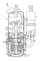
- FIG. 1 is a longitudinal sectional view of a compressor and a configuration diagram of a refrigeration cycle apparatus according to the first embodiment.
- FIG. 2 is a cross-sectional view of a compression mechanism unit included in the compressor according to the first embodiment.
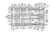
- FIG. 3 is a schematic longitudinal sectional view of the compression mechanism section in the first embodiment.
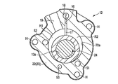
- FIG. 4 is a plan view of the first bearing in the first embodiment when viewed from the axial direction of the rotary shaft.
- FIG. 5 is a plan view showing another example of the first bearing in the first embodiment.
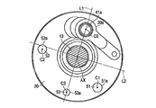
- FIG. 6 is a plan view showing still another example of the first bearing in the first embodiment.
- FIG. 7 is a graph showing the effect of the first embodiment.
- FIG. 8 is a longitudinal sectional view of a compressor according to the second embodiment.
- FIG. 9 is a schematic longitudinal sectional view of a compression mechanism unit included in the compressor according to the second embodiment.
- FIG. 1 is a longitudinal sectional view of a rotary compressor 1 according to the first embodiment and a configuration diagram of a refrigeration cycle apparatus R.
- the rotary compressor 1 is simply referred to as the compressor 1.
- the refrigeration cycle apparatus R includes a compressor 1, a condenser 2 as a radiator, an expansion valve (expansion device) 3, an evaporator 4 as a heat absorber, an accumulator 5, a refrigerant pipe P, and a suction pipe VP.
- the refrigerant pipe P sequentially connects the compressor 1, the condenser 2, the expansion valve 3, the evaporator 4, and the accumulator 5.
- the accumulator 5 and the compressor 1 are connected by two suction pipes VP.
- the compressor 1 includes an airtight container 10, an electric motor unit 11 as a driving element, a compression mechanism unit 12 as a compression element, and a rotating shaft 13.
- the electric motor unit 11 and the compression mechanism unit 12 are accommodated in the sealed container 10 and are connected to each other via the rotation shaft 13.
- the inside of the sealed container 10 stores lubricating oil at the bottom, and the remaining space is filled with a gas refrigerant that is an example of a working fluid.
- the direction from the electric motor unit 11 toward the compression mechanism unit 12 along the rotation shaft 13 is referred to as “lower” or simply “lower”, and the opposite direction is referred to as “upward” or simply “up”.
- the sealed container 10 includes a discharge pipe 10a provided on the upper wall and two suction pipes VP provided on the side walls.
- a refrigerant pipe P is connected to the discharge pipe 10a.
- the electric motor unit 11 includes a stator 14 and a rotor 15.
- the rotor 15 is fixed to the rotating shaft 13.
- the stator 14 is fixed to the inner peripheral wall of the sealed container 10 with the inner peripheral surface thereof facing the outer peripheral surface of the rotor 15 with a slight gap.
- the compression mechanism unit 12 is located below the motor unit 11.
- the compression mechanism unit 12 includes a first bearing (main bearing) 20, a second bearing (sub bearing) 21, a first cylinder 22, a second cylinder 23, a first roller 24, a second roller 25, A partition plate 26, a first muffler 27, and a second muffler 28 are provided.
- the first bearing 20 is fixed to the sealed container 10 via a fixing member 29, for example.
- the first bearing 20, the first cylinder 22, the partition plate 26, the second cylinder 23, and the second bearing 21 are arranged in this order from the electric motor unit 11 side, and are fixed to each other by, for example, co-fastening.
- the 1st bearing 20 and the 2nd bearing 21 are supporting the rotating shaft 13 rotatably.
- the first muffler 27 is attached to the upper surface of the first bearing 20.
- a first muffler chamber 31 is formed between the first muffler 27 and the first bearing 20.
- the first muffler 27 has a plurality of communication holes 27 a that allow communication between the first muffler chamber 31 and the space in the sealed container 10.
- the second muffler 28 is attached to the lower surface of the second bearing 21.
- a second muffler chamber 32 is formed between the second muffler 28 and the second bearing 21.
- the first cylinder 22 has a circular first cylinder chamber 22a.
- the second cylinder 23 has a circular second cylinder chamber 23a.
- the first cylinder 22 and the second cylinder 23 are arranged coaxially with respect to the center AX of the rotating shaft 13, for example.
- the partition plate 26 is disposed between the first cylinder 22 and the second cylinder 23.
- the partition plate 26 is divided into a first portion 26 a and a second portion 26 b that are arranged in the axial direction (vertical direction in the drawing) of the rotary shaft 13.
- the first portion 26a and the second portion 26b have, for example, a disk shape in which an opening for passing the rotating shaft 13 is provided at the center.
- a third muffler chamber 33 is formed by recesses formed on the lower surface of the first portion 26 a and the upper surface of the second portion 26 b, respectively.
- the rotary shaft 13 has a first eccentric portion 13a and a second eccentric portion 13b that protrude in a direction orthogonal to the axial direction.
- the first eccentric portion 13a and the second eccentric portion 13b are eccentric with a phase difference of, for example, about 180 ° with respect to the center AX of the rotating shaft 13.
- the inner peripheral surface of the hollow first roller 24 is fitted to the first eccentric portion 13a.
- the inner peripheral surface of the hollow second roller 25 is fitted into the second eccentric portion 13b.
- the first eccentric portion 13a and the first roller 24 are disposed in the first cylinder chamber 22a.
- the second eccentric portion 13b and the second roller 25 are disposed in the second cylinder chamber 23a.
- the first roller 24 rolls in a state where a part of the outer peripheral surface is in contact with the inner peripheral wall of the first cylinder chamber 22a.
- the second roller 25 rolls in a state where a part of the outer peripheral surface is in contact with the inner peripheral wall of the second cylinder chamber 23a.
- the upper side of the first cylinder chamber 22a is closed by the first bearing 20, and the lower side is closed by the first portion 26a.
- the second cylinder chamber 23 a is closed on the upper side by the second portion 26 b and closed on the lower side by the second bearing 21.
- the gas refrigerant supplied through each suction pipe VP is led to the first cylinder chamber 22a and the second cylinder chamber 23a, respectively. As will be described in detail later, these gas refrigerants are compressed in the first cylinder chamber 22a and the second cylinder chamber 23a as the rotating shaft 13 rotates.
- the gas refrigerant compressed in the first cylinder chamber 22 a is discharged into the first muffler chamber 31 via the first valve mechanism 41 provided in the first bearing 20.
- the gas refrigerant compressed in the second cylinder chamber 23 a is discharged into the second muffler chamber 32 via the second valve mechanism 42 provided in the second bearing 21.
- the third valve mechanism 43 is provided in the first portion 26 a of the partition plate 26, and the fourth valve mechanism 44 is provided in the second portion 26 b of the partition plate 26. That is, the gas refrigerant compressed in the first cylinder chamber 22a is discharged to the third muffler chamber 33 through the third valve mechanism 43, and the gas refrigerant compressed in the second cylinder chamber 23a is discharged to the fourth valve. It is discharged into the third muffler chamber 33 through the mechanism 44.
- the gas refrigerant discharged to the second muffler chamber 32 and the gas refrigerant discharged to the third muffler chamber 33 pass through the first communication passage 51 and the second communication passage 52 (see FIG. 3), which will be described later, respectively.
- an auxiliary communication path 53 that communicates all of the first muffler chamber 31, the second muffler chamber 32, and the third muffler chamber 33 is provided.
- the high-temperature and high-pressure gas refrigerant discharged into the first muffler chamber 31, the second muffler chamber 32, and the third muffler chamber 33 merges in the first muffler chamber 31, and then enters the sealed container 10. Supplied.
- the gas refrigerant in the sealed container 10 is guided to the condenser 2 through the discharge pipe 10 a and the refrigerant pipe P and condensed in the condenser 2.
- the condensed refrigerant is expanded and depressurized by the expansion valve 3, evaporated by the evaporator 4, and gas-liquid separated by the accumulator 5.
- the gas refrigerant separated into gas and liquid by the accumulator 5 is supplied to the first cylinder chamber 22a and the second cylinder chamber 23a via the suction pipes VP, and is compressed again.
- FIG. 2 is a cross-sectional view of the compression mechanism section 12 at the position of the first cylinder 22.
- the vane slot 16 is formed in the first cylinder 22.
- the vane slot 16 extends linearly in the radial direction of the first cylinder chamber 22a.
- a vane 17 is inserted into the vane slot 16 so as to be movable along the radial direction of the first cylinder chamber 22a.
- the vane 17 is always urged toward the first cylinder chamber 22a by an urging member 18 that is, for example, a coil spring.
- the tip of the vane 17 is slidably in contact with the outer peripheral surface of the first roller 24.
- the first cylinder chamber 22a is partitioned by the vane 17 into a suction chamber R1 and a compression chamber R2.
- the first cylinder 22 is formed with a suction path 19 that leads to the suction chamber R1.
- a gas refrigerant is supplied from the suction passage 19 through the suction pipe VP.
- the rotating shaft 13 rotates, the volumes of the suction chamber R1 and the compression chamber R2 change with the eccentric rotation of the eccentric portion 13a and the first roller 24. Thereby, the gas refrigerant is compressed.
- the compressed gas refrigerant is discharged from the compression chamber R2 to the first muffler chamber 31 through the first valve mechanism 41 and from the compression chamber R2 to the third muffler chamber through the third valve mechanism 43. 33 is discharged.
- a plurality of bolt holes H, a first communication path 51, a second communication path 52, and an auxiliary communication path 53 are provided in the first cylinder 22.
- some of the bolt holes are omitted.
- the cross-sectional structure of the compression mechanism 12 at the position of the second cylinder 23 is the same as that shown in FIG. That is, the vane slot 16 is also provided in the second cylinder 23, and the vane 17 and the biasing member 18 are accommodated in the vane slot 16. Then, the gas refrigerant sucked from the suction pipe VP is supplied to the suction chamber R1 through the suction passage 19, and is compressed along with the eccentric rotation of the eccentric portion 13b and the second roller 25. The compressed gas refrigerant is discharged from the compression chamber R2 to the second muffler chamber 32 via the second valve mechanism 42 described above, and from the compression chamber R2 to the third muffler chamber via the fourth valve mechanism 44 described above. 33 is discharged.
- the structure in which the compression mechanism unit 12 compresses the gas refrigerant is not limited to the example in FIG.
- the compression mechanism unit 12 may have a so-called swing structure in which a vane and a roller are integrated.
- FIG. 3 is a schematic longitudinal sectional view of the compression mechanism section 12. This cross section passes through the first valve mechanism 41, the second valve mechanism 42, the third valve mechanism 43, the fourth valve mechanism 44, the first communication path 51, the second communication path 52, and the auxiliary communication path 53 described above. In addition, the compression mechanism portion 12 is cut in the circumferential direction of the rotary shaft 13.
- the first valve mechanism 41 provided in the first bearing 20 includes a first discharge port 41a, a first discharge valve 41b, and a first restriction plate 41c.
- the first discharge port 41a discharges the gas refrigerant from the first cylinder chamber 22a to the first muffler chamber 31.
- the first discharge valve 41b closes the first discharge port 41a when the first cylinder chamber 22a is at a low pressure, and opens the first discharge port 41a when the first cylinder chamber 22a is at a high pressure.
- the first regulating plate 41c regulates the maximum opening degree of the first discharge valve 41b.
- the first discharge port 41 a, the first discharge valve 41 b, and the first restricting plate 41 c are disposed inside a recess 20 a provided on the upper surface of the first bearing 20.
- the second valve mechanism 42 provided in the second bearing 21 includes a second discharge port 42a, a second discharge valve 42b, and a second restriction plate 42c.
- the second discharge port 42a discharges the gas refrigerant from the second cylinder chamber 23a to the second muffler chamber 32.
- the second discharge valve 42b closes the second discharge port 42a when the second cylinder chamber 23a is at a low pressure, and opens the second discharge port 42a when the second cylinder chamber 23a is at a high pressure.
- the second regulating plate 42c regulates the maximum opening degree of the second discharge valve 42b.
- the second discharge port 42 a, the second discharge valve 42 b, and the second restricting plate 42 c are disposed inside a recess 21 a provided on the lower surface of the second bearing 21.
- the third valve mechanism 43 provided in the first portion 26a of the partition plate 26 includes a third discharge port 43a, a third discharge valve 43b, and a third restriction plate 43c.
- the third discharge port 43a discharges the gas refrigerant from the first cylinder chamber 22a to the third muffler chamber 33.
- the third discharge valve 43b closes the third discharge port 43a when the first cylinder chamber 22a is at a low pressure, and opens the third discharge port 43a when the first cylinder chamber 22a is at a high pressure.
- the third regulating plate 43c regulates the maximum opening degree of the third discharge valve 43b.
- the fourth valve mechanism 44 provided in the second portion 26b of the partition plate 26 includes a fourth discharge port 44a, a fourth discharge valve 44b, and a fourth restriction plate 44c.
- the fourth discharge port 44a discharges the gas refrigerant from the second cylinder chamber 23a to the third muffler chamber 33.
- the fourth discharge valve 44b closes the fourth discharge port 44a when the second cylinder chamber 23a is at a low pressure, and opens the fourth discharge port 44a when the second cylinder chamber 23a is at a high pressure.
- the fourth regulating plate 44c regulates the maximum opening degree of the fourth discharge valve 44b.
- the first communication path 51 passes through the first bearing 20, the first cylinder 22, the first portion 26a, the second portion 26b, the second cylinder 23, and the second bearing 21, and includes the first muffler chamber 31 and the second muffler.
- the chamber 32 is open.
- the second muffler chamber 32 and the first muffler chamber 31 communicate with each other, and the gas refrigerant discharged to the second muffler chamber 32 is supplied to the first muffler chamber 31 via the first communication path 51.
- the second communication passage 52 passes through the first bearing 20, the first cylinder 22, and the first portion 26 a and opens to the first muffler chamber 31 and the third muffler chamber 33.
- the third muffler chamber 33 and the first muffler chamber 31 communicate with each other, and the gas refrigerant discharged to the third muffler chamber 33 is supplied to the first muffler chamber 31 via the second communication passage 52.
- the auxiliary communication path 53 passes through the first bearing 20, the first cylinder 22, the first portion 26 a, the second portion 26 b, the second cylinder 23, and the second bearing 21, and includes a first muffler chamber 31 and a second muffler chamber. 32 and the third muffler chamber 33 are opened. As a result, all of the first muffler chamber 31, the second muffler chamber 32, and the third muffler chamber 33 communicate with each other, and the gas refrigerant discharged to the second muffler chamber 32 and the third muffler chamber 33 passes through the auxiliary communication passage 53. To the first muffler chamber 31.
- the first communication path 51, the second communication path 52, and the auxiliary communication path 53 extend, for example, in parallel with the center AX of the rotating shaft 13.
- the centers of the first discharge port 41a, the second discharge port 42a, the third discharge port 43a, and the fourth discharge port 44a are aligned along a straight line parallel to the center AX of the rotating shaft 13, for example.
- first communication passages 51 that communicate the first muffler chamber 31 and the second muffler chamber 32 may be provided.
- second communication passages 52 communicating with the first muffler chamber 31 and the third muffler chamber 33 may be provided, or all of the first muffler chamber 31, the second muffler chamber 32, and the third muffler chamber 33 may be provided.
- a plurality of auxiliary communication passages 53 that communicate with each other may be provided.
- the opening of the first communication passage 51 in the first muffler chamber 31 is the first communication port 51a
- the opening of the second communication passage 52 in the first muffler chamber 31 is the second communication port 52a
- the first muffler chamber is referred to as an auxiliary port 53a.
- the gas refrigerant from the second muffler chamber 32 and the third muffler chamber 33 joins the first muffler chamber 31. Therefore, if the positions of the first discharge port 41a, the first communication port 51a, the second communication port 52a, and the auxiliary port 53a are close to each other, gas refrigerant concentrates on a specific location in the first muffler chamber 31, Channel loss can increase. Further, since the gas refrigerant is heated to a high temperature, the temperature distribution of the components such as the first bearing 20 and the first muffler 27 can be non-uniform. Hereinafter, a configuration for suppressing such an increase in flow path loss and uneven temperature distribution will be described.
- FIG. 4 is a plan view of the upper surface of the first bearing 20 as viewed from the axial direction of the rotary shaft 13.
- the first discharge valve 41b, the first restricting plate 41c, and the bolt hole are not shown.
- a straight line passing through the center C0 of the first discharge port 41a and the center AX of the rotating shaft 13 is defined as a first straight line L1
- a straight line orthogonal to the first straight line L1 and passing through the center AX of the rotating shaft 13 is defined as a second straight line L2.
- the center C1 of the first communication port 51a is located in one of the two areas of the first muffler chamber 31 defined by the first straight line L1, and the center C2 of the second communication port 52a is located in the other. positioned.
- the center C0 of the first discharge port 41a is located in one of the two areas of the first muffler chamber 31 defined by the second straight line L2, and the center C1 and the second communication port of the first communication port 51a are located on the other side.
- the center C2 of 52a is located.
- the distance between the first communication port 51a and the first discharge port 41a is smaller than the distance between the auxiliary port 53a and the first discharge port 41a.
- the distance between the second communication port 52a and the first discharge port 41a is smaller than the distance between the auxiliary port 53a and the first discharge port 41a.
- the cross-sectional area of the first communication port 51a (or the first communication path 51) is smaller than the cross-sectional area of the first discharge port 41a.
- the cross-sectional area of the second communication port 52a (or the second communication path 52) is smaller than the cross-sectional area of the first discharge port 41a.
- the cross-sectional area of the auxiliary port 53a (or auxiliary communication path 53) is larger than the cross-sectional area of the first communication port 51a (or first communication path 51) or the second communication port 52a (or second communication path 52). Is small.
- the distance between the second discharge port 42a and the opening of the first communication passage 51 is smaller than the distance between the second discharge port 42a and the opening of the auxiliary communication passage 53.
- the distance between the third discharge port 43 a and the fourth discharge port 44 a and the opening of the second communication passage 52 is set so that the third discharge port 43 a, the fourth discharge port 44 a and the auxiliary communication passage 53 It becomes smaller than the distance between the openings.
- the opening of the communication path having a large cross-sectional area that is, a small flow path loss
- the opening of the communication path having a large cross-sectional area that is, a small flow path loss
- FIG. This figure is a plan view of the upper surface of the first bearing 20 as seen from the axial direction of the rotary shaft 13 as in FIG.
- the center C0 of the first discharge port 41a and the center C2 of the second communication port 52a are located in one of the two areas of the first muffler chamber 31 defined by the second straight line L2, and the other
- the center C1 of the first communication port 51a is located.
- the center C0 of the first discharge port 41a and the center C1 of the first communication port 51a are located in one of the two regions of the first muffler chamber 31 defined by the second straight line L2, and the second communication port 52a is located in the other.
- the center C2 may be located.
- FIG. 1 is a plan view of the upper surface of the first bearing 20 as viewed from the axial direction of the rotary shaft 13.
- the positions of the first discharge port 41a, the first communication port 51a, the second communication port 52a, and the auxiliary port 53a are as follows. It is the same as FIG.
- each of the angles around the center of the rotation shaft 13 between the centers of two adjacent ports among the first discharge port 41a, the first communication port 51a, and the second communication port 52a is It is in the range of ⁇ that satisfies the following [Formula 1].
- a straight line L11 that connects the center C0 of the first discharge port 41a and the center AX of the rotation shaft 13, and the center C1 of the first communication port 51a and the center AX of the rotation shaft 13 are defined.
- a straight line L12 to be connected and a straight line L13 to connect the center C2 of the second communication port 52a and the center AX of the rotating shaft 13 are defined.
- the angle ⁇ 1 between the straight line L11 and the straight line L12, the angle ⁇ 2 between the straight line L12 and the straight line L13, and the angle ⁇ 3 between the straight line L13 and the straight line L11 are all in the range of [Expression 1].
- the position of each port may be determined so that The angles ⁇ 1, ⁇ 2, and ⁇ 3 may be the same or different from each other.
- the gas refrigerant can be more uniformly dispersed in the first muffler chamber 31.
- the method for determining the position of each port using [Equation 1] and the method for determining the position of each port using the first straight line L1 and the second straight line L2 can be used in combination.
- the inventor measured the temperature distribution of the first bearing 20 in each of the following cases 1 to 4 in order to verify the effect of the present embodiment.
- Both the center C1 of the first communication port 51a and the center C2 of the second communication port 52a are located in one of the two areas of the first muffler chamber 31 defined by the first straight line L1.
- the center C1 of the first communication port 51a is located in one of the two areas of the first muffler chamber 31 defined by the first straight line L1, and the center C2 of the second communication port 52a is located on the other.
- the center C0 of the first discharge port 41a is located in one of the two areas of the first muffler chamber 31 defined by the second straight line L2, and the first in the other.
- FIG. 7 shows the maximum temperature difference (maximum temperature-minimum temperature) in the temperature distribution of the first bearing 20 in cases 1 to 4 described above.
- the maximum temperature difference exceeded 20 ° C, but in Case 2, it was reduced to about 10 ° C, less than half of that.
- the maximum temperature difference was further reduced, and in case 4 it was 1/5 or less of case 1.
- an auxiliary communication path 53 that communicates the first muffler chamber 31, the second muffler chamber 32, and the third muffler chamber 33 is provided.
- the third muffler chamber 33 is closer to the first muffler chamber 31 than the second muffler chamber 32, the flow path loss from the third muffler chamber 33 to the first muffler chamber 31 is from the second muffler chamber 32 to the first muffler chamber. Less than channel loss up to 31. Therefore, the total cross-sectional area of the discharge port of the third muffler chamber 33 may be larger than the total cross-sectional area of the discharge port of the second muffler chamber 32. With such a configuration, the total flow loss in the compression mechanism section 12 is reduced, and the compressor 1 can be improved in performance.
- the “total cross-sectional area of the discharge port of the third muffler chamber 33” corresponds to the sum of the cross-sectional areas of the third discharge port 43a and the fourth discharge port 44a in the present embodiment. When there is one port, it corresponds to the cross-sectional area of the port, and when there are three or more discharge ports of the third muffler chamber 33, it corresponds to the sum of the cross-sectional areas of these ports.
- total cross-sectional area of the discharge port of the second muffler chamber 32 corresponds to the cross-sectional area of the second discharge port 42a in the present embodiment, but when there are two or more discharge ports of the second muffler chamber 32, This corresponds to the sum of the cross-sectional areas of these ports.
- various suitable effects can be obtained from this embodiment.
- FIG. 8 is a longitudinal sectional view of the compressor 100 according to the present embodiment. Elements that are the same as or similar to those of the compressor 1 according to the first embodiment are denoted by the same reference numerals.
- the compressor 100 has a three-cylinder structure including a third cylinder 101 in addition to the first cylinder 22 and the second cylinder 23.
- the third cylinder 101 has a third cylinder chamber 101a.
- the compressor 100 includes a third roller 102 disposed in the third cylinder chamber 101a, a first partition plate 103 disposed between the first cylinder 22 and the third cylinder 101, a second cylinder 23, and a second cylinder 23. And a second partition plate 104 disposed between the three cylinders 101.
- the first bearing 20, the first cylinder 22, the first partition plate 103, the third cylinder 101, the second partition plate 104, the second cylinder 23, and the second bearing 21 are arranged in this order from the motor unit 11 side. For example, they are fixed together by tightening.
- the first partition plate 103 is divided into a first portion 103a and a second portion 103b arranged in the axial direction (vertical direction in the drawing) of the rotary shaft 13. Similar to the partition plate 26 of the first embodiment, a third muffler chamber 110 is formed by recesses respectively formed on the lower surface of the first portion 103a and the upper surface of the second portion 103b.
- the upper side of the first cylinder chamber 22 a is closed by the first bearing 20, and the lower side is closed by the first portion 103 a of the first partition plate 103.
- the second cylinder chamber 23 a is closed on the upper side by the second partition plate 104 and closed on the lower side by the second bearing 21.
- the third cylinder chamber 101 a is closed on the upper side by the second portion 103 b of the first partition plate 103 and closed on the lower side by the second partition plate 104.
- the rotary shaft 13 has a third eccentric portion 13c protruding in a direction orthogonal to the axial direction in addition to the first eccentric portion 13a and the second eccentric portion 13b.
- the first eccentric portion 13a, the second eccentric portion 13b, and the third eccentric portion 13c are eccentric with a phase difference of, for example, about 120 ° with respect to the center AX of the rotating shaft 13.
- each eccentric part may be eccentric with another phase difference.
- An inner peripheral surface of a hollow third roller 102 is fitted into the third eccentric portion 13c and is disposed in the third cylinder chamber 101a. As the rotation shaft 13 rotates, the third roller 102 rolls with a part of the outer peripheral surface in contact with the inner peripheral wall of the third cylinder chamber 101a.
- the gas refrigerant supplied from the suction pipe VP is guided to the second cylinder chamber 23 a and the third cylinder chamber 101 a through a suction path provided inside the second partition plate 104.
- the specific configuration for compressing the gas refrigerant in the third cylinder chamber 101a can be the one described above with reference to FIG.
- the gas refrigerant compressed in the first cylinder chamber 22 a is discharged to the first muffler chamber 31 via the first valve mechanism 41.
- the gas refrigerant compressed in the second cylinder chamber 23 a is discharged to the second muffler chamber 32 via the second valve mechanism 42.
- the gas refrigerant compressed in the third cylinder chamber 101 a is discharged into the third muffler chamber 110 via the third valve mechanism 111 provided in the second portion 103 b of the first partition plate 103.
- the gas refrigerant compressed in the three cylinder chambers is discharged to different muffler chambers.
- FIG. 9 is a schematic longitudinal sectional view of the compression mechanism section 12. This cross-section passes through the first valve mechanism 41, the second valve mechanism 42, the third valve mechanism 111, the first communication path 51, the second communication path 52, and the auxiliary communication path 53 described above, so This corresponds to the compression mechanism section 12 cut in the circumferential direction.
- the configurations of the first valve mechanism 41 and the second valve mechanism 42 are the same as in the first embodiment.
- the third valve mechanism 111 includes a third discharge port 111a, a third discharge valve 111b, and a third restriction plate 111c.
- the third discharge port 111a discharges the gas refrigerant from the third cylinder chamber 101a to the third muffler chamber 110.
- the third discharge valve 111b closes the third discharge port 111a when the third cylinder chamber 101a is at a low pressure, and opens the third discharge port 111a when the third cylinder chamber 101a is at a high pressure.
- the third regulating plate 111c regulates the maximum opening degree of the third discharge valve 111b.
- the centers of the first discharge port 41a, the second discharge port 42a, and the third discharge port 111a are arranged along a straight line parallel to the center AX of the rotating shaft 13, for example.
- the first communication passage 51 passes through the first bearing 20, the first cylinder 22, the first portion 103 a, the second portion 103 b, the third cylinder 101, the second partition plate 104, the second cylinder 23, and the second bearing 21.
- the first muffler chamber 31 and the second muffler chamber 32 are open.
- the second communication passage 52 passes through the first bearing 20, the first cylinder 22, and the first portion 103 a of the first partition plate 103, and opens to the first muffler chamber 31 and the third muffler chamber 110.
- the auxiliary communication path 53 passes through the first bearing 20, the first cylinder 22, the first portion 103 a, the second portion 103 b, the third cylinder 101, the second partition plate 104, the second cylinder 23, and the second bearing 21.
- the first muffler chamber 31, the second muffler chamber 32, and the third muffler chamber 110 are opened.
- first communication passages 51 that communicate the first muffler chamber 31 and the second muffler chamber 32 may be provided.
- a plurality of second communication passages 52 communicating with the first muffler chamber 31 and the third muffler chamber 110 may be provided, or all of the first muffler chamber 31, the second muffler chamber 32, and the third muffler chamber 110 may be provided.
- a plurality of auxiliary communication passages 53 that communicate with each other may be provided.
- the first bearing 20 includes a first communication port 51 a of the first communication path 51, a second communication port 52 a of the second communication path 52, and an auxiliary port 53 a of the auxiliary communication path 53. Is provided.
- the positional relationship among the first discharge port 41a, the first communication port 51a, the second communication port 52a, and the auxiliary port 53a can be the same as in the first embodiment.
- the first discharge valve 41b, the second discharge valve 42b, and the third discharge valve are arranged because the phases of the eccentric portions 13a to 13c are shifted from each other.
- the opening / closing timing of 111b is different from each other.
- a compressor including three muffler chambers is disclosed.
- the number of muffler chambers provided in the compressor is not limited to three, and may be four or more.
- the first straight line L1 and the second straight line L2 described above are used for the positions of the discharge port, the communication port, and the auxiliary port provided in the first muffler chamber where the gas refrigerant from the other muffler chambers merges. It can be determined by a determination method or a determination method using [Formula 1].
- the number of communication ports provided in the first muffler chamber is, for example, three or more.
- a part of the three or more communication ports may be arranged in one of the two areas partitioned by the first straight line L1, and the rest may be arranged in the other area.
- the discharge port may be disposed in one of the two regions partitioned by the second straight line L2, and at least one of the three or more communication ports may be disposed in the other region.
- the angle ⁇ between the centers of two adjacent ports among the discharge port and the three or more communication ports may satisfy [Equation 1].
- a compressor including two cylinder chambers is disclosed, and in the second embodiment, a compressor including three cylinder chambers is disclosed.
- the number of cylinder chambers provided in the compressor is not limited to two or three, and may be four or more.
- R Refrigeration cycle apparatus, 1,100: Rotary compressor, 10: Airtight container, 11: Electric motor part, 12: Compression mechanism part, 13: Rotating shaft, 20: First bearing, 21: Second bearing, 22 ... 1st cylinder, 23 ... 2nd cylinder, 24 ... 1st roller, 25 ... 2nd roller, 26 ... Partition plate, 31 ... 1st muffler chamber, 32 ... 2nd muffler chamber, 33 ... 3rd muffler chamber, 41a ... 1st discharge port, 51 ... 1st communication path, 52 ... 2nd communication path, 51a ... 1st communication port, 52a ... 2nd communication port, 53 ... Auxiliary communication path, 53a ... Auxiliary port, L1 ... 1st straight line, L2 is the second straight line.
Landscapes
- Engineering & Computer Science (AREA)
- Mechanical Engineering (AREA)
- General Engineering & Computer Science (AREA)
- Physics & Mathematics (AREA)
- Thermal Sciences (AREA)
- Applications Or Details Of Rotary Compressors (AREA)
Abstract
Description
[第1実施形態]
図1は、第1実施形態に係る回転式圧縮機1の縦断面図および冷凍サイクル装置Rの構成図である。以下の説明においては、回転式圧縮機1を単に圧縮機1と呼ぶ。冷凍サイクル装置Rは、圧縮機1と、放熱器である凝縮器2と、膨張弁(膨張装置)3と、吸熱器である蒸発器4と、アキュームレータ5と、冷媒管Pと、吸込管VPとを備えている。冷媒管Pは、圧縮機1、凝縮器2、膨張弁3、蒸発器4、アキュームレータ5を順次接続している。アキュームレータ5と圧縮機1は、2本の吸込管VPで接続されている。
電動機部11は、ステータ14と、ロータ15とを備えている。ロータ15は、回転軸13に固定されている。ステータ14は、その内周面がロータ15の外周面と僅かな隙間を介して対向した状態で、密閉容器10の内周壁に固定されている。
仕切板26は、第1シリンダ22と第2シリンダ23の間に配置されている。仕切板26は、回転軸13の軸方向(図中の上下方向)に並ぶ第1部分26aと第2部分26bとに分割されている。第1部分26aおよび第2部分26bは、例えば中心に回転軸13を通すための開口が設けられた円盤状である。図1の例においては、第1部分26aの下面および第2部分26bの上面にそれぞれ形成された凹部により、第3マフラ室33が形成されている。
各吸込管VPを介して供給されるガス冷媒は、それぞれ第1シリンダ室22aおよび第2シリンダ室23aに導かれる。詳しくは後述するが、これらのガス冷媒は回転軸13の回転に伴い第1シリンダ室22aおよび第2シリンダ室23aにおいて圧縮される。第1シリンダ室22aにて圧縮されたガス冷媒は、第1軸受20に設けられた第1弁機構41を介して第1マフラ室31に吐出される。第2シリンダ室23aにて圧縮されたガス冷媒は、第2軸受21に設けられた第2弁機構42を介して第2マフラ室32に吐出される。
第2シリンダ23の位置における圧縮機構部12の断面構造は、図2に示したものと同様である。すなわち、第2シリンダ23にもベーンスロット16が設けられ、このベーンスロット16にベーン17と付勢部材18が収容されている。そして、吸込管VPから吸入されたガス冷媒が吸入路19を通じて吸入室R1に供給され、偏心部13bおよび第2ローラ25の偏心回転に伴って圧縮される。圧縮されたガス冷媒は、上述の第2弁機構42を介して圧縮室R2から第2マフラ室32に吐出されるとともに、上述の第4弁機構44を介して圧縮室R2から第3マフラ室33に吐出される。
以下、このような流路損失の増大や温度分布の不均一を抑制するための構成について説明する。
図4の例では、第1直線L1にて区画される第1マフラ室31の2つの領域の一方に第1連通ポート51aの中心C1が位置し、他方に第2連通ポート52aの中心C2が位置している。このような配置であれば、第1連通ポート51aと第2連通ポート52aの位置を分散することができるので、上述の流路損失および温度分布の不均一を抑制することができる。
[式1] 360°/(N+1)<θ<360°/(N-1)
ここに、Nは圧縮機構部12が備えるマフラ室の数である。本実施形態ではN=3であるため、90°<θ<180°となる。マフラ室の数は4以上であってもよい。したがって、Nは3以上の整数となる。
なお、[式1]を用いた各ポートの位置の決定方法と、上述の第1直線L1および第2直線L2を用いた各ポートの位置の決定方法とは、併用することができる。
第1直線L1にて区画される第1マフラ室31の2つの領域の一方に第1連通ポート51aの中心C1および第2連通ポート52aの中心C2の双方が位置する。
[ケース2]
図4のように、第1直線L1にて区画される第1マフラ室31の2つの領域の一方に第1連通ポート51aの中心C1が位置し、他方に第2連通ポート52aの中心C2が位置する。
[ケース3]
ケース2の構成に加え、図4のように、第2直線L2にて区画される第1マフラ室31の2つの領域の一方に第1吐出ポート41aの中心C0が位置し、他方に第1連通ポート51aの中心C1および第2連通ポート52aの中心C2の双方が位置する。
[ケース4]
ケース2,3の構成に加え、図6のように、角度θ1,θ2,θ3が上述の[式1]を満たす。
以上述べた他にも、本実施形態からは種々の好適な効果を得ることができる。
第2実施形態について説明する。本実施形態では、圧縮機に適用し得る他の例を開示する。圧縮機に関して特に言及しない構成、および、圧縮機を除く冷凍サイクル装置の構成については第1実施形態と同様である。
第1吐出ポート41a、第2吐出ポート42a、および第3吐出ポート111aの中心は、例えば回転軸13の中心AXと平行な直線に沿って並んでいる。
その他、本実施形態からは第1実施形態と同様の効果を得ることができる。
Claims (7)
- 回転軸と、前記回転軸を回転させる電動機部と、前記回転軸に連結された圧縮機構部と、前記回転軸、前記電動機部、および前記圧縮機構部を収容する密閉容器と、を備える回転式圧縮機であって、
前記圧縮機構部は、
前記回転軸の回転に伴い作動流体を圧縮する圧縮室と、
前記回転軸の軸方向に並び、前記圧縮室にて圧縮された前記作動流体を吐出する吐出ポートがそれぞれ設けられた複数のマフラ室と、を備え、
前記複数のマフラ室は、第1マフラ室と、第2マフラ室と、第3マフラ室とを含み、
前記第1マフラ室には、前記第2マフラ室を経た前記作動流体を前記第1マフラ室に供給する第1連通ポートと、前記第3マフラ室を経た前記作動流体を前記第1マフラ室に供給する第2連通ポートと、が設けられ、
前記軸方向から見て、前記第1マフラ室の前記吐出ポートの中心と前記回転軸の中心とを通る第1直線にて区画される前記第1マフラ室の2つの領域の一方に前記第1連通ポートの中心が位置し、他方に前記第2連通ポートの中心が位置している、
回転式圧縮機。 - 前記軸方向から見て、前記回転軸の中心を通り且つ前記第1直線と直交する第2直線にて区画される前記第1マフラ室の2つの領域の一方に前記第1マフラ室の前記吐出ポートの中心が位置し、他方に前記第1連通ポートおよび前記第2連通ポートの少なくとも一方の中心が位置している、
請求項1に記載の回転式圧縮機。 - 前記圧縮機構部は、3以上の整数であるNの前記マフラ室を備え、
前記第1マフラ室において、前記吐出ポートと、他の前記マフラ室からの前記作動流体を前記第1マフラ室に供給する各連通ポートとのうち、隣り合う2つのポートの中心間の前記回転軸の中心を中心とした回転方向における角度の各々が、
360°/(N+1)<θ<360°/(N-1)
を満たすθの範囲にある、
請求項2に記載の回転式圧縮機。 - 前記圧縮機構部は、前記複数のマフラ室の全てを連通する補助連通路をさらに備え、
前記第1マフラ室には、前記補助連通路を通る前記作動流体を供給する補助ポートが設けられ、
前記第1マフラ室において、前記補助ポートと前記吐出ポートとの間の距離よりも、前記第1連通ポートまたは前記第2連通ポートと前記吐出ポートとの間の距離の方が小さい、
請求項1に記載の回転式圧縮機。 - 前記軸方向において、前記第3マフラ室は、前記第2マフラ室よりも前記第1マフラ室に近い位置にあり、
前記第3マフラ室の前記吐出ポートの総断面積が、前記第2マフラ室の前記吐出ポートの総断面積よりも大きい、
請求項1乃至4のうちいずれか1項に記載の回転式圧縮機。 - 前記圧縮機構部は、前記第1マフラ室、前記第2マフラ室、および前記第3マフラ室の各前記吐出ポートにそれぞれ設けられた複数の吐出弁を備え、
前記複数の吐出弁が開閉するタイミングが全て異なる、
請求項1乃至5のうちいずれか1項に記載の回転式圧縮機。 - 請求項1乃至6のうちいずれか1項に記載の回転式圧縮機と、
前記回転式圧縮機に接続された放熱器と、
前記放熱器に接続された膨張装置と、
前記膨張装置に接続された吸熱器と、
を備える冷凍サイクル装置。
Priority Applications (4)
| Application Number | Priority Date | Filing Date | Title |
|---|---|---|---|
| JP2019504292A JP6743277B2 (ja) | 2017-03-10 | 2017-03-10 | 回転式圧縮機および冷凍サイクル装置 |
| CN201780084058.0A CN110199126B (zh) | 2017-03-10 | 2017-03-10 | 旋转式压缩机以及制冷循环装置 |
| PCT/JP2017/009849 WO2018163434A1 (ja) | 2017-03-10 | 2017-03-10 | 回転式圧縮機および冷凍サイクル装置 |
| KR1020197028474A KR102290735B1 (ko) | 2017-03-10 | 2017-03-10 | 회전식 압축기 및 냉동 사이클 장치 |
Applications Claiming Priority (1)
| Application Number | Priority Date | Filing Date | Title |
|---|---|---|---|
| PCT/JP2017/009849 WO2018163434A1 (ja) | 2017-03-10 | 2017-03-10 | 回転式圧縮機および冷凍サイクル装置 |
Publications (1)
| Publication Number | Publication Date |
|---|---|
| WO2018163434A1 true WO2018163434A1 (ja) | 2018-09-13 |
Family
ID=63448207
Family Applications (1)
| Application Number | Title | Priority Date | Filing Date |
|---|---|---|---|
| PCT/JP2017/009849 Ceased WO2018163434A1 (ja) | 2017-03-10 | 2017-03-10 | 回転式圧縮機および冷凍サイクル装置 |
Country Status (4)
| Country | Link |
|---|---|
| JP (1) | JP6743277B2 (ja) |
| KR (1) | KR102290735B1 (ja) |
| CN (1) | CN110199126B (ja) |
| WO (1) | WO2018163434A1 (ja) |
Citations (4)
| Publication number | Priority date | Publication date | Assignee | Title |
|---|---|---|---|---|
| JPH10213087A (ja) * | 1997-01-30 | 1998-08-11 | Toshiba Corp | ロータリコンプレッサ |
| JP2002221156A (ja) * | 2001-01-25 | 2002-08-09 | Mitsubishi Electric Corp | 密閉型圧縮機 |
| JP2009002299A (ja) * | 2007-06-25 | 2009-01-08 | Daikin Ind Ltd | ロータリ圧縮機 |
| JP2013083245A (ja) * | 2011-09-29 | 2013-05-09 | Toshiba Carrier Corp | 密閉型圧縮機及び冷凍サイクル装置 |
-
2017
- 2017-03-10 JP JP2019504292A patent/JP6743277B2/ja active Active
- 2017-03-10 KR KR1020197028474A patent/KR102290735B1/ko active Active
- 2017-03-10 WO PCT/JP2017/009849 patent/WO2018163434A1/ja not_active Ceased
- 2017-03-10 CN CN201780084058.0A patent/CN110199126B/zh active Active
Patent Citations (4)
| Publication number | Priority date | Publication date | Assignee | Title |
|---|---|---|---|---|
| JPH10213087A (ja) * | 1997-01-30 | 1998-08-11 | Toshiba Corp | ロータリコンプレッサ |
| JP2002221156A (ja) * | 2001-01-25 | 2002-08-09 | Mitsubishi Electric Corp | 密閉型圧縮機 |
| JP2009002299A (ja) * | 2007-06-25 | 2009-01-08 | Daikin Ind Ltd | ロータリ圧縮機 |
| JP2013083245A (ja) * | 2011-09-29 | 2013-05-09 | Toshiba Carrier Corp | 密閉型圧縮機及び冷凍サイクル装置 |
Also Published As
| Publication number | Publication date |
|---|---|
| KR102290735B1 (ko) | 2021-08-17 |
| CN110199126B (zh) | 2021-07-06 |
| JP6743277B2 (ja) | 2020-08-19 |
| CN110199126A (zh) | 2019-09-03 |
| JPWO2018163434A1 (ja) | 2019-07-25 |
| KR20190116527A (ko) | 2019-10-14 |
Similar Documents
| Publication | Publication Date | Title |
|---|---|---|
| JP6022247B2 (ja) | 密閉型圧縮機及び冷凍サイクル装置 | |
| JP7066495B2 (ja) | 密閉型圧縮機及び冷凍サイクル装置 | |
| WO2013172144A1 (ja) | 気体圧縮機 | |
| JP6267360B2 (ja) | 回転式圧縮機及び冷凍サイクル装置 | |
| JP2015129475A (ja) | 電動圧縮機 | |
| JP6177741B2 (ja) | 回転式圧縮機及び冷凍サイクル装置 | |
| CN109312742B (zh) | 密闭型压缩机以及制冷循环装置 | |
| JP2015129476A (ja) | 電動圧縮機 | |
| JP6732898B2 (ja) | 密閉型圧縮機および冷凍サイクル装置 | |
| JP6743277B2 (ja) | 回転式圧縮機および冷凍サイクル装置 | |
| WO2019171540A1 (ja) | ロータリコンプレッサおよび冷凍サイクル装置 | |
| JP6467311B2 (ja) | 圧縮機及び冷凍サイクル装置 | |
| CN112771273A (zh) | 旋转压缩机以及制冷循环装置 | |
| KR102222539B1 (ko) | 밀폐형 압축기 및 냉동 사이클 장치 | |
| JP6930026B2 (ja) | ロータリコンプレッサおよび冷凍サイクル装置 | |
| JP6005786B2 (ja) | 密閉型圧縮機及び冷凍サイクル装置 | |
| JP6430904B2 (ja) | 圧縮機及び冷凍サイクル装置 | |
| JP2020118053A (ja) | 回転式圧縮機および冷凍サイクル装置 | |
| JP2018053874A (ja) | 密閉型圧縮機及び冷凍サイクル装置 |
Legal Events
| Date | Code | Title | Description |
|---|---|---|---|
| 121 | Ep: the epo has been informed by wipo that ep was designated in this application |
Ref document number: 17899800 Country of ref document: EP Kind code of ref document: A1 |
|
| ENP | Entry into the national phase |
Ref document number: 2019504292 Country of ref document: JP Kind code of ref document: A |
|
| NENP | Non-entry into the national phase |
Ref country code: DE |
|
| ENP | Entry into the national phase |
Ref document number: 20197028474 Country of ref document: KR Kind code of ref document: A |
|
| 122 | Ep: pct application non-entry in european phase |
Ref document number: 17899800 Country of ref document: EP Kind code of ref document: A1 |