WO2018159760A1 - 表面処理鋼板 - Google Patents
表面処理鋼板 Download PDFInfo
- Publication number
- WO2018159760A1 WO2018159760A1 PCT/JP2018/007782 JP2018007782W WO2018159760A1 WO 2018159760 A1 WO2018159760 A1 WO 2018159760A1 JP 2018007782 W JP2018007782 W JP 2018007782W WO 2018159760 A1 WO2018159760 A1 WO 2018159760A1
- Authority
- WO
- WIPO (PCT)
- Prior art keywords
- plating layer
- layer
- plating
- steel sheet
- treated steel
- Prior art date
Links
- 229910000831 Steel Inorganic materials 0.000 title claims abstract description 141
- 239000010959 steel Substances 0.000 title claims abstract description 141
- 238000007747 plating Methods 0.000 claims abstract description 250
- 229910045601 alloy Inorganic materials 0.000 claims abstract description 80
- 239000000956 alloy Substances 0.000 claims abstract description 80
- 229910017709 Ni Co Inorganic materials 0.000 claims abstract description 54
- 229910003267 Ni-Co Inorganic materials 0.000 claims abstract description 54
- 229910003262 Ni‐Co Inorganic materials 0.000 claims abstract description 54
- 239000000463 material Substances 0.000 claims abstract description 46
- 229910003271 Ni-Fe Inorganic materials 0.000 claims abstract description 27
- 238000004458 analytical method Methods 0.000 claims description 32
- 238000000034 method Methods 0.000 claims description 25
- 229910052759 nickel Inorganic materials 0.000 claims description 24
- 229910052742 iron Inorganic materials 0.000 claims description 19
- 238000002149 energy-dispersive X-ray emission spectroscopy Methods 0.000 claims description 17
- 238000005259 measurement Methods 0.000 claims description 14
- 239000012535 impurity Substances 0.000 claims description 10
- 238000004611 spectroscopical analysis Methods 0.000 claims description 3
- 239000011159 matrix material Substances 0.000 claims 1
- 239000010410 layer Substances 0.000 description 197
- PXHVJJICTQNCMI-UHFFFAOYSA-N nickel Substances [Ni] PXHVJJICTQNCMI-UHFFFAOYSA-N 0.000 description 110
- 239000002585 base Substances 0.000 description 38
- XEEYBQQBJWHFJM-UHFFFAOYSA-N iron Substances [Fe] XEEYBQQBJWHFJM-UHFFFAOYSA-N 0.000 description 36
- 238000005275 alloying Methods 0.000 description 19
- 230000000052 comparative effect Effects 0.000 description 14
- 238000004519 manufacturing process Methods 0.000 description 14
- VEXZGXHMUGYJMC-UHFFFAOYSA-M Chloride anion Chemical compound [Cl-] VEXZGXHMUGYJMC-UHFFFAOYSA-M 0.000 description 11
- 238000000137 annealing Methods 0.000 description 9
- QAOWNCQODCNURD-UHFFFAOYSA-N Sulfuric acid Chemical compound OS(O)(=O)=O QAOWNCQODCNURD-UHFFFAOYSA-N 0.000 description 8
- 239000000203 mixture Substances 0.000 description 8
- 238000012545 processing Methods 0.000 description 8
- 239000011347 resin Substances 0.000 description 8
- 229920005989 resin Polymers 0.000 description 8
- 239000012298 atmosphere Substances 0.000 description 7
- 229910052739 hydrogen Inorganic materials 0.000 description 7
- 238000004090 dissolution Methods 0.000 description 6
- 230000000694 effects Effects 0.000 description 6
- OKTJSMMVPCPJKN-UHFFFAOYSA-N Carbon Chemical compound [C] OKTJSMMVPCPJKN-UHFFFAOYSA-N 0.000 description 5
- QAOWNCQODCNURD-UHFFFAOYSA-L Sulfate Chemical compound [O-]S([O-])(=O)=O QAOWNCQODCNURD-UHFFFAOYSA-L 0.000 description 5
- 229910052799 carbon Inorganic materials 0.000 description 5
- 230000007423 decrease Effects 0.000 description 5
- 238000000151 deposition Methods 0.000 description 5
- 230000008021 deposition Effects 0.000 description 5
- 238000009792 diffusion process Methods 0.000 description 5
- 239000007788 liquid Substances 0.000 description 5
- 241000080590 Niso Species 0.000 description 4
- 239000000654 additive Substances 0.000 description 4
- 230000002950 deficient Effects 0.000 description 4
- 238000009713 electroplating Methods 0.000 description 4
- NUJOXMJBOLGQSY-UHFFFAOYSA-N manganese dioxide Chemical compound O=[Mn]=O NUJOXMJBOLGQSY-UHFFFAOYSA-N 0.000 description 4
- BDAGIHXWWSANSR-UHFFFAOYSA-N methanoic acid Natural products OC=O BDAGIHXWWSANSR-UHFFFAOYSA-N 0.000 description 4
- 239000003973 paint Substances 0.000 description 4
- 238000000550 scanning electron microscopy energy dispersive X-ray spectroscopy Methods 0.000 description 4
- 239000002344 surface layer Substances 0.000 description 4
- 238000012546 transfer Methods 0.000 description 4
- QTBSBXVTEAMEQO-UHFFFAOYSA-N Acetic acid Chemical compound CC(O)=O QTBSBXVTEAMEQO-UHFFFAOYSA-N 0.000 description 3
- LFQSCWFLJHTTHZ-UHFFFAOYSA-N Ethanol Chemical compound CCO LFQSCWFLJHTTHZ-UHFFFAOYSA-N 0.000 description 3
- LYCAIKOWRPUZTN-UHFFFAOYSA-N Ethylene glycol Chemical compound OCCO LYCAIKOWRPUZTN-UHFFFAOYSA-N 0.000 description 3
- VEXZGXHMUGYJMC-UHFFFAOYSA-N Hydrochloric acid Chemical compound Cl VEXZGXHMUGYJMC-UHFFFAOYSA-N 0.000 description 3
- OKKJLVBELUTLKV-UHFFFAOYSA-N Methanol Chemical compound OC OKKJLVBELUTLKV-UHFFFAOYSA-N 0.000 description 3
- MUBZPKHOEPUJKR-UHFFFAOYSA-N Oxalic acid Chemical compound OC(=O)C(O)=O MUBZPKHOEPUJKR-UHFFFAOYSA-N 0.000 description 3
- 238000002441 X-ray diffraction Methods 0.000 description 3
- 230000001133 acceleration Effects 0.000 description 3
- 230000000996 additive effect Effects 0.000 description 3
- 239000007864 aqueous solution Substances 0.000 description 3
- 239000007806 chemical reaction intermediate Substances 0.000 description 3
- 239000010960 cold rolled steel Substances 0.000 description 3
- 238000011156 evaluation Methods 0.000 description 3
- 235000019253 formic acid Nutrition 0.000 description 3
- 238000013507 mapping Methods 0.000 description 3
- 238000000465 moulding Methods 0.000 description 3
- 239000006259 organic additive Substances 0.000 description 3
- 229910052760 oxygen Inorganic materials 0.000 description 3
- 238000004544 sputter deposition Methods 0.000 description 3
- 239000000126 substance Substances 0.000 description 3
- NLXLAEXVIDQMFP-UHFFFAOYSA-N Ammonia chloride Chemical compound [NH4+].[Cl-] NLXLAEXVIDQMFP-UHFFFAOYSA-N 0.000 description 2
- WGCNASOHLSPBMP-UHFFFAOYSA-N Glycolaldehyde Chemical compound OCC=O WGCNASOHLSPBMP-UHFFFAOYSA-N 0.000 description 2
- UFHFLCQGNIYNRP-UHFFFAOYSA-N Hydrogen Chemical compound [H][H] UFHFLCQGNIYNRP-UHFFFAOYSA-N 0.000 description 2
- MHAJPDPJQMAIIY-UHFFFAOYSA-N Hydrogen peroxide Chemical compound OO MHAJPDPJQMAIIY-UHFFFAOYSA-N 0.000 description 2
- NBBJYMSMWIIQGU-UHFFFAOYSA-N Propionic aldehyde Chemical compound CCC=O NBBJYMSMWIIQGU-UHFFFAOYSA-N 0.000 description 2
- 229910004298 SiO 2 Inorganic materials 0.000 description 2
- FAPWRFPIFSIZLT-UHFFFAOYSA-M Sodium chloride Chemical compound [Na+].[Cl-] FAPWRFPIFSIZLT-UHFFFAOYSA-M 0.000 description 2
- QVGXLLKOCUKJST-UHFFFAOYSA-N atomic oxygen Chemical compound [O] QVGXLLKOCUKJST-UHFFFAOYSA-N 0.000 description 2
- KGBXLFKZBHKPEV-UHFFFAOYSA-N boric acid Chemical compound OB(O)O KGBXLFKZBHKPEV-UHFFFAOYSA-N 0.000 description 2
- 239000004327 boric acid Substances 0.000 description 2
- 238000011088 calibration curve Methods 0.000 description 2
- 239000002131 composite material Substances 0.000 description 2
- 238000001816 cooling Methods 0.000 description 2
- 230000006866 deterioration Effects 0.000 description 2
- XBDQKXXYIPTUBI-UHFFFAOYSA-N dimethylselenoniopropionate Natural products CCC(O)=O XBDQKXXYIPTUBI-UHFFFAOYSA-N 0.000 description 2
- 239000003792 electrolyte Substances 0.000 description 2
- 238000004453 electron probe microanalysis Methods 0.000 description 2
- 239000007789 gas Substances 0.000 description 2
- 238000010438 heat treatment Methods 0.000 description 2
- 239000001257 hydrogen Substances 0.000 description 2
- 239000000543 intermediate Substances 0.000 description 2
- 150000002500 ions Chemical class 0.000 description 2
- 230000014759 maintenance of location Effects 0.000 description 2
- 229910052748 manganese Inorganic materials 0.000 description 2
- 239000011572 manganese Substances 0.000 description 2
- 230000007246 mechanism Effects 0.000 description 2
- LNOPIUAQISRISI-UHFFFAOYSA-N n'-hydroxy-2-propan-2-ylsulfonylethanimidamide Chemical compound CC(C)S(=O)(=O)CC(N)=NO LNOPIUAQISRISI-UHFFFAOYSA-N 0.000 description 2
- 239000007773 negative electrode material Substances 0.000 description 2
- 239000012299 nitrogen atmosphere Substances 0.000 description 2
- 230000003647 oxidation Effects 0.000 description 2
- 238000007254 oxidation reaction Methods 0.000 description 2
- 239000001301 oxygen Substances 0.000 description 2
- 230000008569 process Effects 0.000 description 2
- 238000004080 punching Methods 0.000 description 2
- 230000003014 reinforcing effect Effects 0.000 description 2
- 238000005096 rolling process Methods 0.000 description 2
- 150000003839 salts Chemical class 0.000 description 2
- 230000001629 suppression Effects 0.000 description 2
- OSWFIVFLDKOXQC-UHFFFAOYSA-N 4-(3-methoxyphenyl)aniline Chemical compound COC1=CC=CC(C=2C=CC(N)=CC=2)=C1 OSWFIVFLDKOXQC-UHFFFAOYSA-N 0.000 description 1
- 229910017061 Fe Co Inorganic materials 0.000 description 1
- 229910000655 Killed steel Inorganic materials 0.000 description 1
- HBBGRARXTFLTSG-UHFFFAOYSA-N Lithium ion Chemical compound [Li+] HBBGRARXTFLTSG-UHFFFAOYSA-N 0.000 description 1
- 229910001209 Low-carbon steel Inorganic materials 0.000 description 1
- PWHULOQIROXLJO-UHFFFAOYSA-N Manganese Chemical compound [Mn] PWHULOQIROXLJO-UHFFFAOYSA-N 0.000 description 1
- IKHGUXGNUITLKF-XPULMUKRSA-N acetaldehyde Chemical compound [14CH]([14CH3])=O IKHGUXGNUITLKF-XPULMUKRSA-N 0.000 description 1
- 235000011054 acetic acid Nutrition 0.000 description 1
- 230000002411 adverse Effects 0.000 description 1
- 239000003513 alkali Substances 0.000 description 1
- 235000019270 ammonium chloride Nutrition 0.000 description 1
- 229910052796 boron Inorganic materials 0.000 description 1
- ZTQSAGDEMFDKMZ-UHFFFAOYSA-N butyric aldehyde Natural products CCCC=O ZTQSAGDEMFDKMZ-UHFFFAOYSA-N 0.000 description 1
- 229910052801 chlorine Inorganic materials 0.000 description 1
- 150000001805 chlorine compounds Chemical class 0.000 description 1
- 239000011248 coating agent Substances 0.000 description 1
- 238000000576 coating method Methods 0.000 description 1
- 239000000470 constituent Substances 0.000 description 1
- 230000007797 corrosion Effects 0.000 description 1
- 238000005260 corrosion Methods 0.000 description 1
- 238000011161 development Methods 0.000 description 1
- 238000010586 diagram Methods 0.000 description 1
- 238000001035 drying Methods 0.000 description 1
- 238000003411 electrode reaction Methods 0.000 description 1
- 238000010828 elution Methods 0.000 description 1
- 238000005265 energy consumption Methods 0.000 description 1
- 238000003912 environmental pollution Methods 0.000 description 1
- 230000001747 exhibiting effect Effects 0.000 description 1
- 239000012467 final product Substances 0.000 description 1
- 238000007429 general method Methods 0.000 description 1
- 229910002804 graphite Inorganic materials 0.000 description 1
- 239000010439 graphite Substances 0.000 description 1
- 230000006872 improvement Effects 0.000 description 1
- 238000007689 inspection Methods 0.000 description 1
- 230000003993 interaction Effects 0.000 description 1
- 229910001416 lithium ion Inorganic materials 0.000 description 1
- 229910052987 metal hydride Inorganic materials 0.000 description 1
- 229910021645 metal ion Inorganic materials 0.000 description 1
- 238000001465 metallisation Methods 0.000 description 1
- WSFSSNUMVMOOMR-NJFSPNSNSA-N methanone Chemical compound O=[14CH2] WSFSSNUMVMOOMR-NJFSPNSNSA-N 0.000 description 1
- -1 nickel metal hydride Chemical class 0.000 description 1
- 239000003960 organic solvent Substances 0.000 description 1
- 235000006408 oxalic acid Nutrition 0.000 description 1
- 229910052698 phosphorus Inorganic materials 0.000 description 1
- 239000007774 positive electrode material Substances 0.000 description 1
- 238000003825 pressing Methods 0.000 description 1
- BDERNNFJNOPAEC-UHFFFAOYSA-N propan-1-ol Chemical compound CCCO BDERNNFJNOPAEC-UHFFFAOYSA-N 0.000 description 1
- 235000019260 propionic acid Nutrition 0.000 description 1
- IUVKMZGDUIUOCP-BTNSXGMBSA-N quinbolone Chemical compound O([C@H]1CC[C@H]2[C@H]3[C@@H]([C@]4(C=CC(=O)C=C4CC3)C)CC[C@@]21C)C1=CCCC1 IUVKMZGDUIUOCP-BTNSXGMBSA-N 0.000 description 1
- 230000009467 reduction Effects 0.000 description 1
- 238000000682 scanning probe acoustic microscopy Methods 0.000 description 1
- 229910052710 silicon Inorganic materials 0.000 description 1
- 239000011780 sodium chloride Substances 0.000 description 1
- 235000002639 sodium chloride Nutrition 0.000 description 1
- 230000000087 stabilizing effect Effects 0.000 description 1
- 238000003860 storage Methods 0.000 description 1
- 238000006467 substitution reaction Methods 0.000 description 1
- 229910052717 sulfur Inorganic materials 0.000 description 1
- 238000004381 surface treatment Methods 0.000 description 1
- 229910002058 ternary alloy Inorganic materials 0.000 description 1
- 230000000007 visual effect Effects 0.000 description 1
- XLYOFNOQVPJJNP-UHFFFAOYSA-N water Substances O XLYOFNOQVPJJNP-UHFFFAOYSA-N 0.000 description 1
Images

Classifications
-
- C—CHEMISTRY; METALLURGY
- C25—ELECTROLYTIC OR ELECTROPHORETIC PROCESSES; APPARATUS THEREFOR
- C25D—PROCESSES FOR THE ELECTROLYTIC OR ELECTROPHORETIC PRODUCTION OF COATINGS; ELECTROFORMING; APPARATUS THEREFOR
- C25D5/00—Electroplating characterised by the process; Pretreatment or after-treatment of workpieces
- C25D5/10—Electroplating with more than one layer of the same or of different metals
- C25D5/12—Electroplating with more than one layer of the same or of different metals at least one layer being of nickel or chromium
-
- B—PERFORMING OPERATIONS; TRANSPORTING
- B32—LAYERED PRODUCTS
- B32B—LAYERED PRODUCTS, i.e. PRODUCTS BUILT-UP OF STRATA OF FLAT OR NON-FLAT, e.g. CELLULAR OR HONEYCOMB, FORM
- B32B15/00—Layered products comprising a layer of metal
- B32B15/01—Layered products comprising a layer of metal all layers being exclusively metallic
- B32B15/013—Layered products comprising a layer of metal all layers being exclusively metallic one layer being formed of an iron alloy or steel, another layer being formed of a metal other than iron or aluminium
- B32B15/015—Layered products comprising a layer of metal all layers being exclusively metallic one layer being formed of an iron alloy or steel, another layer being formed of a metal other than iron or aluminium the said other metal being copper or nickel or an alloy thereof
-
- C—CHEMISTRY; METALLURGY
- C22—METALLURGY; FERROUS OR NON-FERROUS ALLOYS; TREATMENT OF ALLOYS OR NON-FERROUS METALS
- C22C—ALLOYS
- C22C19/00—Alloys based on nickel or cobalt
- C22C19/03—Alloys based on nickel or cobalt based on nickel
-
- C—CHEMISTRY; METALLURGY
- C22—METALLURGY; FERROUS OR NON-FERROUS ALLOYS; TREATMENT OF ALLOYS OR NON-FERROUS METALS
- C22C—ALLOYS
- C22C38/00—Ferrous alloys, e.g. steel alloys
- C22C38/001—Ferrous alloys, e.g. steel alloys containing N
-
- C—CHEMISTRY; METALLURGY
- C22—METALLURGY; FERROUS OR NON-FERROUS ALLOYS; TREATMENT OF ALLOYS OR NON-FERROUS METALS
- C22C—ALLOYS
- C22C38/00—Ferrous alloys, e.g. steel alloys
- C22C38/002—Ferrous alloys, e.g. steel alloys containing In, Mg, or other elements not provided for in one single group C22C38/001 - C22C38/60
-
- C—CHEMISTRY; METALLURGY
- C22—METALLURGY; FERROUS OR NON-FERROUS ALLOYS; TREATMENT OF ALLOYS OR NON-FERROUS METALS
- C22C—ALLOYS
- C22C38/00—Ferrous alloys, e.g. steel alloys
- C22C38/02—Ferrous alloys, e.g. steel alloys containing silicon
-
- C—CHEMISTRY; METALLURGY
- C22—METALLURGY; FERROUS OR NON-FERROUS ALLOYS; TREATMENT OF ALLOYS OR NON-FERROUS METALS
- C22C—ALLOYS
- C22C38/00—Ferrous alloys, e.g. steel alloys
- C22C38/04—Ferrous alloys, e.g. steel alloys containing manganese
-
- C—CHEMISTRY; METALLURGY
- C22—METALLURGY; FERROUS OR NON-FERROUS ALLOYS; TREATMENT OF ALLOYS OR NON-FERROUS METALS
- C22C—ALLOYS
- C22C38/00—Ferrous alloys, e.g. steel alloys
- C22C38/06—Ferrous alloys, e.g. steel alloys containing aluminium
-
- C—CHEMISTRY; METALLURGY
- C22—METALLURGY; FERROUS OR NON-FERROUS ALLOYS; TREATMENT OF ALLOYS OR NON-FERROUS METALS
- C22C—ALLOYS
- C22C38/00—Ferrous alloys, e.g. steel alloys
- C22C38/12—Ferrous alloys, e.g. steel alloys containing tungsten, tantalum, molybdenum, vanadium, or niobium
-
- C—CHEMISTRY; METALLURGY
- C22—METALLURGY; FERROUS OR NON-FERROUS ALLOYS; TREATMENT OF ALLOYS OR NON-FERROUS METALS
- C22C—ALLOYS
- C22C38/00—Ferrous alloys, e.g. steel alloys
- C22C38/14—Ferrous alloys, e.g. steel alloys containing titanium or zirconium
-
- C—CHEMISTRY; METALLURGY
- C25—ELECTROLYTIC OR ELECTROPHORETIC PROCESSES; APPARATUS THEREFOR
- C25D—PROCESSES FOR THE ELECTROLYTIC OR ELECTROPHORETIC PRODUCTION OF COATINGS; ELECTROFORMING; APPARATUS THEREFOR
- C25D3/00—Electroplating: Baths therefor
- C25D3/02—Electroplating: Baths therefor from solutions
- C25D3/12—Electroplating: Baths therefor from solutions of nickel or cobalt
-
- C—CHEMISTRY; METALLURGY
- C25—ELECTROLYTIC OR ELECTROPHORETIC PROCESSES; APPARATUS THEREFOR
- C25D—PROCESSES FOR THE ELECTROLYTIC OR ELECTROPHORETIC PRODUCTION OF COATINGS; ELECTROFORMING; APPARATUS THEREFOR
- C25D5/00—Electroplating characterised by the process; Pretreatment or after-treatment of workpieces
- C25D5/48—After-treatment of electroplated surfaces
- C25D5/50—After-treatment of electroplated surfaces by heat-treatment
-
- C—CHEMISTRY; METALLURGY
- C25—ELECTROLYTIC OR ELECTROPHORETIC PROCESSES; APPARATUS THEREFOR
- C25D—PROCESSES FOR THE ELECTROLYTIC OR ELECTROPHORETIC PRODUCTION OF COATINGS; ELECTROFORMING; APPARATUS THEREFOR
- C25D7/00—Electroplating characterised by the article coated
-
- H—ELECTRICITY
- H01—ELECTRIC ELEMENTS
- H01M—PROCESSES OR MEANS, e.g. BATTERIES, FOR THE DIRECT CONVERSION OF CHEMICAL ENERGY INTO ELECTRICAL ENERGY
- H01M50/00—Constructional details or processes of manufacture of the non-active parts of electrochemical cells other than fuel cells, e.g. hybrid cells
- H01M50/10—Primary casings; Jackets or wrappings
- H01M50/116—Primary casings; Jackets or wrappings characterised by the material
- H01M50/117—Inorganic material
- H01M50/119—Metals
-
- H—ELECTRICITY
- H01—ELECTRIC ELEMENTS
- H01M—PROCESSES OR MEANS, e.g. BATTERIES, FOR THE DIRECT CONVERSION OF CHEMICAL ENERGY INTO ELECTRICAL ENERGY
- H01M50/00—Constructional details or processes of manufacture of the non-active parts of electrochemical cells other than fuel cells, e.g. hybrid cells
- H01M50/10—Primary casings; Jackets or wrappings
- H01M50/116—Primary casings; Jackets or wrappings characterised by the material
- H01M50/124—Primary casings; Jackets or wrappings characterised by the material having a layered structure
- H01M50/1245—Primary casings; Jackets or wrappings characterised by the material having a layered structure characterised by the external coating on the casing
-
- H—ELECTRICITY
- H01—ELECTRIC ELEMENTS
- H01M—PROCESSES OR MEANS, e.g. BATTERIES, FOR THE DIRECT CONVERSION OF CHEMICAL ENERGY INTO ELECTRICAL ENERGY
- H01M50/00—Constructional details or processes of manufacture of the non-active parts of electrochemical cells other than fuel cells, e.g. hybrid cells
- H01M50/10—Primary casings; Jackets or wrappings
- H01M50/131—Primary casings; Jackets or wrappings characterised by physical properties, e.g. gas permeability, size or heat resistance
- H01M50/133—Thickness
-
- B—PERFORMING OPERATIONS; TRANSPORTING
- B32—LAYERED PRODUCTS
- B32B—LAYERED PRODUCTS, i.e. PRODUCTS BUILT-UP OF STRATA OF FLAT OR NON-FLAT, e.g. CELLULAR OR HONEYCOMB, FORM
- B32B2457/00—Electrical equipment
- B32B2457/10—Batteries
-
- C—CHEMISTRY; METALLURGY
- C25—ELECTROLYTIC OR ELECTROPHORETIC PROCESSES; APPARATUS THEREFOR
- C25D—PROCESSES FOR THE ELECTROLYTIC OR ELECTROPHORETIC PRODUCTION OF COATINGS; ELECTROFORMING; APPARATUS THEREFOR
- C25D7/00—Electroplating characterised by the article coated
- C25D7/06—Wires; Strips; Foils
- C25D7/0614—Strips or foils
-
- Y—GENERAL TAGGING OF NEW TECHNOLOGICAL DEVELOPMENTS; GENERAL TAGGING OF CROSS-SECTIONAL TECHNOLOGIES SPANNING OVER SEVERAL SECTIONS OF THE IPC; TECHNICAL SUBJECTS COVERED BY FORMER USPC CROSS-REFERENCE ART COLLECTIONS [XRACs] AND DIGESTS
- Y02—TECHNOLOGIES OR APPLICATIONS FOR MITIGATION OR ADAPTATION AGAINST CLIMATE CHANGE
- Y02E—REDUCTION OF GREENHOUSE GAS [GHG] EMISSIONS, RELATED TO ENERGY GENERATION, TRANSMISSION OR DISTRIBUTION
- Y02E60/00—Enabling technologies; Technologies with a potential or indirect contribution to GHG emissions mitigation
- Y02E60/10—Energy storage using batteries
-
- Y—GENERAL TAGGING OF NEW TECHNOLOGICAL DEVELOPMENTS; GENERAL TAGGING OF CROSS-SECTIONAL TECHNOLOGIES SPANNING OVER SEVERAL SECTIONS OF THE IPC; TECHNICAL SUBJECTS COVERED BY FORMER USPC CROSS-REFERENCE ART COLLECTIONS [XRACs] AND DIGESTS
- Y10—TECHNICAL SUBJECTS COVERED BY FORMER USPC
- Y10T—TECHNICAL SUBJECTS COVERED BY FORMER US CLASSIFICATION
- Y10T428/00—Stock material or miscellaneous articles
- Y10T428/12—All metal or with adjacent metals
- Y10T428/12493—Composite; i.e., plural, adjacent, spatially distinct metal components [e.g., layers, joint, etc.]
- Y10T428/12771—Transition metal-base component
- Y10T428/12861—Group VIII or IB metal-base component
- Y10T428/12937—Co- or Ni-base component next to Fe-base component
Definitions
- the present invention relates to a surface-treated steel sheet.
- This application claims priority based on Japanese Patent Application No. 2017-038958 filed in Japan on March 2, 2017, the contents of which are incorporated herein by reference.
- Ni-plated steel sheets have been used as surface-treated steel sheets for battery containers.
- Ni-plated steel sheets are used as various battery containers such as alkaline manganese dry batteries, lithium ion batteries, battery cans of nickel metal hydride batteries, etc. due to the excellent chemical stability of Ni.
- the method of continuously plating the steel strip before can making is advantageous, so the Ni-plated steel sheet is deep-drawn press processed to produce a positive electrode material, a negative electrode material,
- An increasing number of cases are used in positive electrode cans, which are containers that contain an electrolyte or the like and that also serve as a positive electrode terminal.
- Ni-plated steel sheet for example, as a positive electrode can of a general alkaline battery
- a conductive paint containing graphite is applied to the inner surface of the positive electrode can to maintain contact with the positive electrode mixture.
- an organic solvent-based paint is used, there is a problem of environmental pollution. If a water-based paint is used, energy consumption for drying becomes a problem.
- oxidation of Ni occurs with time, contact resistance increases, and discharge characteristics deteriorate.
- Patent Document 1 Japanese Patent Application Laid-Open No. 2009-129664 discloses a Co plating layer of 0.05 to 0.10 ⁇ m on the upper surface of the Ni plating layer on the inner surface with respect to the problem of deterioration of discharge characteristics due to oxidation of the Ni plating layer.
- a positive electrode can in which
- Patent Document 2 Japanese Patent Application Laid-Open No. 2012-489578 discloses an alkaline battery capable of maintaining superior discharge characteristics, in which the inner surface of a positive electrode can is formed by a multilayer coating of Ni plating and Ni—Co alloy plating. It has been proposed that the thickness of the alloy film is 0.15 to 0.25 ⁇ m and the Co ratio in the alloy is 40 to 60%.
- Patent Document 3 International Publication No. 2012/144743 shows that, in a plated steel sheet in which only Co plating is applied on a Ni plating layer, when used as a battery container using a strong alkaline electrolyte, It is pointed out that Co is eluted with the passage of time and it becomes difficult to maintain the battery characteristics.
- the outermost layer portion of the plating layer is made of an Ni—Co alloy layer, and Co / O by Auger electron spectroscopy analysis on the surface of the Ni—Co alloy layer. It is appropriate to control the Ni value within the range of 0.1 to 1.5.
- Patent Document 4 Japanese Patent Publication No. 3-17916
- a Ni plating layer of 1 to 6 ⁇ m is formed
- a Co plating layer of 0.01 to 1.0 ⁇ m is formed, and then heat-treated at 580 to 710 ° C.
- a cold-rolled steel strip is disclosed.
- the surface-treated steel sheet for alkaline battery cans is required to satisfy both discharge characteristics and leakage resistance as a positive electrode current collector.
- Ni-Co plating is used on the inner surface of the can, compared to the case where Ni plating is used, an increase in resistance to charge transfer between the inner surface of the can and the positive electrode due to storage is suppressed, and a decrease in output of the battery is suppressed. This has the effect of improving the discharge characteristics.
- the surface Co atom concentration of the plating is required to be 20 at% or more.
- Patent Documents 1 to 4 do not fully study from the viewpoint of can workability of steel sheets.
- an object of the present invention is to provide a surface-treated steel sheet having excellent workability while maintaining discharge characteristics and leakage resistance.
- a surface-treated steel sheet according to an aspect of the present invention is a surface-treated steel sheet comprising a steel plate base material and a plating layer comprising Ni, Co, Fe, and impurities provided on the surface of the steel plate base material.
- the plating layer is identified by performing a line analysis of the cross-section of the plating layer from the surface of the surface-treated steel plate toward the steel plate base material by an energy dispersive X-ray analysis method.
- Ni—Co alloy plating layer which is a region between the position where the maximum concentration of Co is 8% by mass for the first time, and the cross section of the plating layer from the surface of the surface-treated steel sheet.
- the position where the mass concentration of Fe is 8% by mass for the first time, the mass concentration of Fe, and the mass concentration of Fe, which are specified by performing the line analysis with the energy dispersive X-ray analysis method toward the steel plate base material Is the same for the first time
- a Ni—Fe alloy layer that is a region between the Ni—Fe alloy layer and a Ni layer that exists between the Ni—Co alloy plating layer and the Ni—Fe alloy layer.
- the total deposition amount is 0.2 to 2.3 g / m 2
- the total deposition amount of Ni is 8.9 g / m 2 or more
- the Ni layer has a thickness of 0.3 to 3.0 ⁇ m.
- the atomic concentration of Co specified by analyzing the surface of the Ni—Co alloy plating layer by X-ray photoelectric spectroscopy is 20 to 70 at%, and the cross section of the plating layer is the energy dispersive X-ray.
- the concentration gradient y in the depth direction of Co in the plating layer obtained by substituting Ip, I 1/5 , and ⁇ x specified by the line analysis by the analysis method into the following formula (1) is 50 to 400% by mass / ⁇ m.
- Ip the peak mass concentration of Co specified by the line analysis
- I 1/5 the mass concentration of 1/5 of Ip
- ⁇ x X 1/5 -Xp
- Xp specified by the line analysis
- X 1/5 specified by the line analysis
- the mass concentration of Co is first I on the side of the steel plate base material than Xp. It is the depth in the unit ⁇ m of the position that becomes 1/5, and the origin of depth measurement is the surface of the plating layer for both X 1/5 and Xp.
- the total adhesion amount of Co may be 0.4 g / m 2 or more in the plating layer.
- the thickness of the Ni layer may be 2.0 ⁇ m or less.
- the total adhesion amount of Co may be 9.5 to 17 g / m 2 in the plating layer.
- the atomic concentration of Co on the surface of the Ni—Co alloy plating layer may be 30 to 60 at%. . (7) In the surface-treated steel sheet according to any one of (1) to (6), the concentration gradient y in the depth direction of Co in the plating layer may be 110 to 300.
- the surface-treated steel sheet of the present invention has high discharge characteristics and leakage resistance, and is excellent in workability.
- the plating layer is difficult to break even when the processing conditions for the battery can are severe while ensuring the battery performance, thereby stabilizing the quality of the battery and improving the yield. It can contribute to cost reduction. Therefore, the present invention can contribute to industrial development.
- the inventors of the present invention repeatedly investigated a surface-treated steel sheet having excellent workability while maintaining discharge characteristics and leakage resistance.
- the present inventors have found that workability can be improved while ensuring the battery performance of the surface-treated steel sheet by optimizing the plating configuration, particularly the concentration gradient in the depth direction of Co.
- the plating configuration particularly the concentration gradient in the depth direction of Co.
- the Co atomic concentration on the surface of the Ni—Co alloy plating layer is set to 20 to 70 at%, a specific Co concentration gradient is formed in the plating depth direction, and the Ni layer is formed below the Ni—Co alloy plating layer. It was found that a surface-treated steel sheet excellent in workability can be obtained while maintaining discharge characteristics and leakage resistance.
- FIG. 1 shows a schematic cross-sectional view of the surface-treated steel sheet according to this embodiment based on the above knowledge.
- a surface-treated steel sheet 10 according to the present embodiment includes a steel sheet base material 1 and a plating layer 2 containing Ni, Co, Fe, and impurities formed on the steel sheet base material 1.
- the impurity of the plating layer 2 means a substance mixed in the plating layer 2 and allowed within a range that does not adversely affect the surface-treated steel sheet 10 according to the present embodiment. Examples of elements that can be contained in the plating layer 2 as impurities include H, O, C, B, S, and Cl.
- the plating layer 2 includes a Ni—Fe alloy layer 3, a Ni layer 4, and a Ni—Co alloy plating layer 5 in order from the surface side of the steel plate base material 1.
- the Ni—Co alloy plating layer 5 is an energy dispersive X-ray analysis method in which the cross section of the plating layer 2 is directed from the surface of the surface-treated steel sheet 10 toward the steel sheet base material 1 ( It is defined as a region between a position where the mass concentration of Co is maximized and a position where the mass concentration of Co is 8 mass% for the first time, which is specified by performing line analysis with EDX).
- the Ni—Fe alloy layer 3 is the mass of Fe specified by performing a line analysis of the cross section of the plating layer 2 from the surface of the surface-treated steel plate 10 toward the steel plate base material 1 by energy dispersive X-ray analysis. It is defined as a region between a position where the concentration is 8 mass% for the first time and a position where the mass concentration of Ni and the mass concentration of Fe are the same for the first time.
- the Ni layer 4 is defined as a layer existing between the Ni—Co alloy plating layer 5 and the Ni—Fe alloy layer 3. Details of the cross-sectional analysis by EDX will be described later.
- a natural oxide film or the like may be formed on the surface of the Ni—Co alloy plating layer 5 in some cases.
- the steel sheet base material 1 of the surface-treated steel sheet 10 according to the present embodiment is not necessarily limited, but a commonly used aluminum-killed (Al-killed) steel or ultra-low carbon steel (for example, ultra-low carbon Ti added) Steel, ultra-low carbon Nb-added steel, ultra-low carbon Ti—Nb-added steel, etc.) can be used as the material. Furthermore, a steel plate to which appropriate amounts of Si, Mn, and P elements are added as reinforcing component elements and a steel plate to which B is added as a grain boundary reinforcing element can be used as the material of the steel plate base material 1. In view of the thickness of the final product, a cold-rolled steel sheet is usually used as the material of the steel sheet base material 1, but is not limited thereto.
- the plating layer 2 includes the Ni—Fe alloy layer 3, the Ni layer 4, and the Ni—Co alloy plating layer 5 in this order from the steel plate base material 1 side.
- the total adhesion amount of Co is set to 0.2 g / m 2 or more. This is because if the total adhesion amount of Co is less than 0.2 g / m 2 , the atomic concentration of Co on the surface of the Ni—Co alloy plating layer 5 described later cannot be ensured, and the discharge characteristics deteriorate.
- the total adhesion amount of Co in the plating layer 2 is set to 2.3 g / m 2 or less.
- the total adhesion amount of Co in the plating layer 2 may be 0.4 g / m 2 or more, 0.6 g / m 2 or more, or 0.8 g / m 2 or more.
- the total adhesion amount of Co in the plating layer 2 may be 2.0 g / m 2 or less, 1.8 g / m 2 or less, or 1.6 g / m 2 or less.
- the total adhesion amount of Ni is 8.9 g / m 2 or more.
- Fe in the steel plate base material 1 diffuses to the surface layer in the process of interdiffusion of Co and Ni to form an alloy, resulting in leakage resistance. This is because the soft Ni layer 4 disappears and the workability may decrease.
- the total adhesion amount of Ni is 17.8 g / m 2 or less.
- the total adhesion amount of Ni in the plating layer 2 9.5 g / m 2 or more, 11.0 g / m 2 or more, or 12.5 g / m 2 may be higher.
- the total adhesion amount of Ni in the plating layer 2 17.0 g / m 2 or less, 15.0 g / m 2 or less, or 14.0 g / m 2 may be less.
- the total deposition amount of Ni and the total deposition amount of Co in the plating layer 2 can be measured by applying a fluorescent X-ray analysis method to the plating layer 2.
- a fluorescent X-ray analysis method for example, RSXaku ZSX Primus II can be used as a means of fluorescent X-ray analysis. If a standard sample with known amounts of adhesion of Ni and Co is prepared in advance and a calibration curve is prepared using this standard sample, the amount of adhesion of Ni and Co to be measured can be determined based on the calibration curve. .
- the atomic concentration of Co obtained by analyzing the surface of the Ni—Co alloy plating layer 5 by X-ray photoelectric spectroscopy (XPS) (hereinafter abbreviated as “surface Co concentration”) is 20 to 70%.
- the surface Co concentration is set in the range of 20 to 70 at% in atomic%.
- the surface Co concentration may be 25 at% or more, 30 at% or more, or 35 at% or more.
- the surface Co concentration may be 65 at% or less, 60 at% or less, or 55 at% or less.
- the surface Co concentration is measured by XPS.
- XPS In measurement by XPS, PHI5600 manufactured by ULVAC-PHI is used, and MgK ⁇ ray is used as the X-ray source.
- the surface treated steel plate 10 with Ar ions is removed in order to remove these effects.
- sputtering the surface of the plating layer 2 it is necessary to measure the atomic concentration of Co. Sputtering may be performed until the influence of dirt and oxide film is eliminated, for example, sputtering may be performed to a depth of 4 nm in terms of SiO 2 .
- the atomic concentration of Co is calculated by regarding the total atomic concentration of Ni, Co, and Fe as 100 at%. That is, the ratio of the molar amount of Co to the total molar amount of Co, Fe, and Ni on the surface of the Ni—Co alloy plating layer 5 is regarded as the atomic concentration of Co on the surface of the Ni—Co alloy plating layer 5. The atomic concentration of Fe and the atomic concentration of Ni on the surface of the Ni—Co alloy plating layer 5 are similarly measured.
- the atomic concentrations of Ni and Fe on the surface of the Ni—Co alloy plating layer 5 are not particularly limited. In order to further secure the liquid leakage resistance of the surface-treated steel sheet 10, the atomic concentration of Fe on the surface of the Ni—Co alloy plating layer 5 may be 4 at% or less, 3 at% or less, or 2 at% or less.
- the concentration gradient y in the depth direction of Co in the plating layer 2 is controlled from the viewpoint of ensuring the workability of the plating layer 2.
- the concentration gradient y [mass% / ⁇ m] in the depth direction of Co in the plating layer 2 is expressed by the following formula: Ip, I 1/5 , and ⁇ x specified by performing a line analysis of the cross section of the plating layer with EDX. Obtained by substitution.
- Ip peak mass concentration of Co in unit mass% specified by line analysis
- I 1/5 mass concentration of 1/5 of Ip
- ⁇ x X 1/5 -Xp
- Xp Depth in units of ⁇ m at the position where the mass concentration of Co is Ip, specified by line analysis
- X 1/5 Depth in the unit ⁇ m at the position where the mass concentration of Co is initially I 1/5 on the steel plate base material 1 side relative to Xp, specified by line analysis
- the origin of depth measurement is the surface of the plating layer 2 for both X 1/5 and Xp.
- the concentration gradient y is a mass concentration gradient of Co.
- This concentration gradient y is set to a range of 50 ⁇ y ⁇ 400.
- the concentration gradient y is less than 50, the alloying of Ni and Co has progressed too much, so that the surface-treated steel sheet 10 tends to be inferior in workability.
- the concentration gradient y exceeds 400, alloying between Ni and Co is insufficient, the surface layer of the plating layer 2 becomes hard, workability deteriorates, and the plating layer 2 is easily peeled off during processing.
- the concentration gradient y may be 70 or more, 90 or more, or 110 or more.
- the concentration gradient y may be 350 or less, 320 or less, or 300 or less.
- the concentration gradient y in the depth direction of Co in the plating layer 2 is obtained by measuring the cross section of the plating layer 2 by energy dispersive X-ray analysis (EDX, for example, SEM-EDX).
- EDX energy dispersive X-ray analysis
- the specific measurement procedure is as follows. First, the surface-treated steel sheet 10 is embedded with resin. Next, a cross section perpendicular to the surface of the surface-treated steel sheet 10 is formed, which is used as an inspection surface and mirror-polished. Then, the cross section of the plating layer 2 is observed at a magnification of 10,000 times, and EDX ray analysis is performed from the resin side (that is, the surface side of the surface-treated steel plate 10) to the steel plate base material 1 side.
- the acceleration voltage is 15 kV
- the irradiation current is 10 nA
- the measurement pitch is 0.025 ⁇ m
- the aperture diameter of the objective lens is 30 ⁇ m ⁇ .
- the mass concentration of each element is calculated on the assumption that the total mass concentration of Ni, Co, and Fe is 100%. That is, the ratio of the mass of Co to the total mass of Ni, Co, and Fe at the measurement point is regarded as the mass concentration of Co at the measurement point.
- the same measurement is performed from the surface side of the surface-treated steel sheet 10, and the mass concentration of Co at the highest Co mass concentration is defined as Ip, and the depth at this position is defined as Xp.
- the EDX ray analysis is performed from the steel plate base material 1 side, and the mass concentration of Co becomes 1/5 (I 1/5 ) of Ip for the first time.
- the depth of the coincident position be X 1/5 .
- the origin of the depth measurement at these positions is the surface of the plating layer 2.
- the surface of the plating layer 2 in this measurement is defined as the interface between the resin and the sample when the resin-embedded sample is observed from the cross section.
- the thicknesses of the Ni—Co alloy plating layer 5 and the Ni layer 4 and Ni—Fe alloy layer 3 below the Ni—Co alloy plating layer 5 are measured by SEM-EDX in a cross section perpendicular to the surface of the surface-treated steel sheet 10 as described above. .
- the thickness of the Ni—Co alloy plating layer 5 is determined from the surface of the plating layer 2 [when the EDX analysis is performed from the resin side to the steel plate base material 1 side, the mass concentration of the plating layer Co becomes Ip. After passing the position, the position until the mass concentration of Co in the plating layer is 8% by mass for the first time] is said.
- the position where the mass concentration of the plating layer Co is Ip substantially coincides with the surface of the plating layer 2, but this is not the case when an oxide film or the like is formed on the surface of the plating layer 2.
- the Ni—Fe alloy layer 3 is [from the position where the mass concentration of Fe in the plating layer becomes 8 mass% for the first time when EDX analysis is performed from the resin side to the steel plate base material 1 side].
- the position where the mass concentration of Ni and the mass concentration of Fe become the same concentration for the first time] is said.
- a layer between the Ni—Co alloy plating layer and the Ni—Fe alloy layer is defined as a Ni layer.
- the thickness of the Ni—Co alloy plating layer 5 is not particularly limited as long as the total deposition amount of Co, the concentration gradient y of Co, and the like are controlled within the above ranges.
- the thickness of the Ni—Co alloy plating layer 5 is generally in the range of 0.1 to 1.5 ⁇ m. .
- the thickness of the Ni—Co alloy plating layer 5 may be 0.2 ⁇ m or more, or 0.5 ⁇ m or more.
- the thickness of the Ni—Co alloy plating layer 5 may be 1.2 ⁇ m or less, 1.0 ⁇ m or less, or 0.8 ⁇ m or less.
- the plating layer 2 can be provided with followability to the steel plate base material 1 when the surface-treated steel plate 10 is processed, and the plating layer 2 can be made difficult to break.
- the thickness of the Ni layer 4 optimum for workability is in the range of 0.3 to 3.0 ⁇ m. If the thickness of the Ni layer 2 is less than 0.3 ⁇ m, the above-described effects cannot be obtained sufficiently.
- the thickness of the Ni layer 2 is more preferably 0.5 ⁇ m or more, 0.8 ⁇ m or more, or 1.0 ⁇ m or more.
- the thickness of the Ni layer 2 is 3. If it exceeds 0 ⁇ m, the cost increases with increasing thickness.
- the thickness of the Ni layer 4 is more preferably 2.0 ⁇ m or less, and further preferably 1.5 ⁇ m or less.
- the Ni—Fe alloy layer 3 is formed by heat treatment after Ni plating and Co plating.
- the Ni—Fe alloy layer 3 has the effect of improving the adhesion of the plating layer 2.
- the thickness of the Ni—Fe alloy layer 3 is not particularly limited. When the surface-treated steel sheet 10 according to the present embodiment is manufactured under manufacturing conditions capable of achieving the above-described requirements, the thickness of the Ni—Fe alloy layer 3 is generally in the range of 0.3 to 1.5 ⁇ m.
- the manufacturing method is as follows. Ni plating, 2. 2. Co plating, and Includes alloying treatment.
- Ni plating In order to obtain the plating layer 2 of the surface-treated steel sheet 10 according to the present embodiment, it is necessary to make all of the Ni plating thickness, Ni plating conditions, Co plating thickness, Co plating conditions, and alloying treatment conditions within an appropriate range.
- the Ni plating referred to here is Ni plating before alloying treatment, and is distinguished from the Ni layer 4 of the surface-treated steel sheet 10 according to the present embodiment after alloying treatment.
- the Ni plating thickness affects the thickness of the intermediate layer in the plating layer 2 of the surface-treated steel sheet 10, that is, the Ni layer 4.
- the Ni plating conditions are considered to affect the atomic concentration of Co on the surface of the Ni—Co alloy plating layer 5, the Co concentration gradient y, the thickness of the Ni layer 4, and the thickness of the Ni—Fe alloy layer 3.
- the Co plating thickness is considered to affect the atomic concentration of Co on the surface of the Ni—Co alloy plating layer 5 and the Co concentration gradient y.
- the Co plating conditions are considered to affect the atomic concentration of Co on the surface of the Ni—Co alloy plating layer 5, the Co concentration gradient y, and the thickness of the Ni layer 4.
- the alloying treatment conditions are considered to affect the atomic concentration of Co on the surface of the Ni—Co alloy plating layer 5, the Co concentration gradient y, the thickness of the Ni layer 4, and the thickness of the Ni—Fe alloy layer 3.
- Ni plating conditions and Co plating conditions affect the plating structure The mechanism by which Ni plating conditions and Co plating conditions affect the plating structure is that the plating conditions affect the amount of plating strain before alloying treatment, and the amount of plating strain affects the Ni—Co diffusion rate and Ni—Fe diffusion rate. It is presumed to be due to influence.
- the plating condition that has the greatest effect on the amount of plating strain is considered to be the type of plating bath.
- Well-known plating baths having a small plating strain include well-known baths (sulfate ion and chloride ion composite baths) and sulfamic acid baths.
- the smaller the amount of plating distortion the better the plating uniformity and coverage, and the smaller the plating damage during processing of the plated steel sheet. Therefore, in a general method for manufacturing a plated steel sheet, it is directed to minimize the amount of plating distortion.
- it is necessary to increase the amount of plating strain before the alloying process for the reasons described above.
- Ni and Co are deposited as plating
- Ni and Co are deposited via some reaction intermediate produced by the interaction between these metal ions and components in the plating bath.
- the structure of this reaction intermediate affects the exchange current density at the time of metal deposition, the exchange current density of the hydrogen electrode reaction, and the like, and consequently affects the amount of plating strain.
- the plating strain is reduced by the presence of NiCl adsorbed atoms as a reaction intermediate due to the coexistence of sulfate ions and chloride ions.
- examples of the plating bath that can obtain an amount of plating strain suitable for the surface-treated steel sheet 10 according to the present embodiment include a sulfuric acid bath, a total chloride bath, and the strain increases in these.
- a bath containing an organic or inorganic additive can be used.
- the Ni—Fe alloy layer 3 When a larger strain than usual is introduced into both Ni plating and Co plating, the Ni—Fe alloy layer 3 may become too thick and the Ni layer 4 may disappear depending on the alloying conditions and the like. it is conceivable that. Moreover, when an organic additive or an inorganic additive is contained in the Ni plating bath, it is considered that these may eutect in the plating layer and reduce the corrosion resistance of the surface-treated steel sheet 10. For this reason, it is preferable to apply normal plating conditions with a small amount of strain to Ni plating, and apply plating conditions with a larger amount of strain than usual to only Co plating.
- a Ni plating layer is formed on the surface of the steel plate base material 1 by electroplating using a Ni plating bath.
- a plating bath usually used in Ni plating such as a watt bath, a sulfamic acid bath, a borofluoride bath, and the like can be used.
- the Ni plating layer has a bath composition of NiSO 4 ⁇ 6H 2 O: 250 to 380 g / L, NiCl 2 ⁇ 6H 2 O: 40 to 80 g / L, and H 3 BO 3 : 20 to 55 g / L as a watt bath.
- a Co plating layer is formed on the Ni plating layer by applying Co plating to the steel plate base material 1 on which the Ni plating layer is formed.
- a Co plating bath that increases the amount of plating strain is used instead of a general Co plating bath.
- the Co plating bath include a sulfuric acid Co bath and a total chloride Co bath.
- the sulfuric acid Co bath is a bath containing Co sulfate as a main component, containing boric acid, sulfuric acid, or a salt thereof as required, and not containing chloride ions in an amount that is considered as an impurity.
- the amount of chloride ions regarded as impurities is, for example, 500 ppm or less.
- the total chloride Co bath is a bath substantially composed of Co chloride alone, or a composite containing Co chloride and other chlorides (for example, Na chloride, K chloride, and ammonium chloride). It is a bath that further contains boric acid, hydrochloric acid, and the like and does not contain sulfate ions in an amount that is considered to be an impurity.
- the amount of sulfate ions regarded as impurities is, for example, 500 ppm or less.
- organic additives and inorganic additives include formic acid, acetic acid, propionic acid, and oxalic acid, and salts thereof, or formaldehyde, methanol, ethanol, acetaldehyde, propanol, propionaldehyde, ethylene glycol, glycol aldehyde. , Hydrogen peroxide, and the like can be used.
- a Co plating layer can be formed under conditions of pH 2 to 3, bath temperature 50 to 60 ° C., and current density 1 to 40 A / dm 2 .
- the steel plate base material 1 on which the Ni plating layer and the Co plating layer are formed is subjected to an alloying treatment, whereby the Ni plating layer and the Co plating layer are thermally diffused to form the Ni—Co alloy plating layer 5.
- the elements are diffused between the Ni plating layer and the steel plate base material 1 to form the Ni—Fe alloy layer 3.
- a continuous annealing method is used as the alloying treatment, the treatment atmosphere is a nitrogen-2-4% hydrogen atmosphere, and the maximum temperature reached by the plated steel sheet base material 1 is 715-900 ° C.
- the holding time is desirably 10 to 40 seconds.
- the surface-treated steel sheet 10 according to the present embodiment can be obtained by forming the above-described predetermined plating layer on the steel sheet base material 1 and alloying it as described above.
- the conditions in the examples are one example of conditions adopted to confirm the feasibility and effects of the present invention.
- the present invention is not limited to this one condition example.
- the present invention can adopt various conditions as long as the object of the present invention is achieved without departing from the gist of the present invention.
- Ni plating (i) bath condition ⁇ NiSO 4 ⁇ 6H 2 O: 340g / L ⁇ NiCl 2 ⁇ 6H 2 O: 70 g / L ⁇ H 3 BO 3 : 45 g / L (Ii) Other plating conditions and bath temperature: 60 ° C Cathode current density: 20 A / dm 2 ⁇ PH: 4.0 2.
- Example 8 the same production conditions as in Examples 1 to 7 were adopted except that the following was adopted as the Co plating conditions.
- Example 9 the production conditions were the same as those of Examples 1 to 8, except that the following was adopted as the Co plating conditions.
- Ni plating (i) bath conditions / NiSO 4 .6H 2 O: 225 g / L ⁇ NiCl 2 ⁇ 6H 2 O: 23 g / L ⁇ H 3 BO 3 : 41 g / L (Ii) Other plating conditions / pH: 3.6 ⁇ Bath temperature: 60 ° C Cathode current density: 20 A / dm 2 2.
- Comparative Example 8 was not batch annealed, but was subjected to continuous annealing at an ultimate temperature of 720 ° C., a holding time of 10 seconds, and an atmosphere N 2 -2% H 2 (oxygen concentration: 50 ppm or less). The production was performed under the same conditions.
- the total adhesion amount of Ni and the total adhesion amount of Co in the plating layer were obtained by punching a 40 mm ⁇ sample from the center of the produced surface-treated steel sheet. It measured by evaluating the total adhesion amount of Ni and Co using the fluorescent X ray analysis method (ZSX Primus II by Rigaku) with respect to the plating layer of this sample.
- the atomic concentration of Co on the surface of the Ni—Co alloy plating layer was obtained by punching a 10 mm ⁇ 10 mm sample from the center of the produced surface-treated steel sheet. This was measured by analyzing with XPS (PHI5600 manufactured by ULVAC-PHI). The X-ray source used was MgK ⁇ , and the acceleration voltage was 15 kV and the current value was 27 mA. The surface of the sample was sputtered 4 nm in terms of SiO 2 using Ar ions, and then the composition of the surface was analyzed. In the composition analysis, the total atomic concentration of Ni, Co, and Fe was considered to be 100 at%.
- concentration gradient y in the depth direction of Co in the plating layer is 10 mm from the center of the produced surface-treated steel sheet.
- a sample of ⁇ 20 mm was punched out and the cross section was analyzed by SEM-EDX ray analysis. The short side of the sample was matched with the direction perpendicular to the rolling direction of the steel plate base material, and the long side of the sample was matched with the rolling direction of the steel plate base material. After embedding the resin, the sample was cut perpendicularly to the surface, and the cut surface was mirror-polished before analysis.
- SEM-EDX uses JEOL JSM-7000F, acceleration voltage is 15kV, irradiation current is 10nA, objective lens aperture diameter is 30 ⁇ m ⁇ , magnification is 10,000 times, and the cross section of the plating layer is line analysis from resin side to steel plate base material side did.
- the measurement elements were Ni, Co, and Fe, and these compositions were calculated assuming that the total mass concentration of Ni, Co, and Fe was 100% by mass. Based on the result of the line analysis, Ip, I 1/5 , Xp, and X 1/5 were calculated by the above-described method, and y was obtained.
- the thickness of the Ni layer, the thickness of the Ni—Fe alloy layer (Ni—Fe layer), and the Ni—Co alloy plating layer (Ni— The thickness of the Co layer was measured. The thickness was measured according to the procedure described above. Note that the Ni layer was defined as the Fe concentration of 8% or less. The above evaluation was calculated with the average of 5 places in a 10,000 times visual field.
- Comparative Examples 2 and 3 were inferior in both battery performance and workability.
- Comparative Example 4 since the annealing temperature was too high, the diffusion of Co and Fe proceeded excessively, the Ni layer was not formed, and the workability was inferior.
- Comparative Example 5 had a high surface Co concentration because the annealing temperature was too low, and was inferior in liquid leakage resistance.
- Comparative Examples 6 and 7 since the annealing time was outside the above-described preferable range, the Co concentration gradient was outside the scope of the invention and the workability was poor.
- Comparative Examples 8 and 9 the diffusion of Co and Fe proceeded excessively due to BAF annealing, the Ni layer was deficient, and Fe diffused in the surface layer of the plating layer.
- Comparative Examples 8 and 9 are inferior in workability.
- “-” In the column of the thickness of the Ni—Co alloy plating layer and the column of the thickness of the Ni—Fe alloy layer in Table 2 indicates that at least one ternary alloy layer of Ni—Fe—Co is present. In other words, the Ni—Co alloy plating layer and the Ni—Fe alloy layer could not be distinguished from each other, indicating that their thickness could not be measured.
- Comparative Example 10 both the surface Co concentration and the Co concentration gradient were out of the scope of the invention, and both leakage resistance and workability were inferior. This is presumably because the composition of the plating bath was inappropriate and the amount of strain of the plating layer before the alloying treatment was small.
- the surface-treated steel sheet of the present invention has high discharge characteristics and leakage resistance, and is excellent in workability.
- the surface-treated steel sheet of the present invention when used as a positive electrode can of an alkaline battery, it is difficult to break even if processed, and thus it can contribute to battery quality improvement by stably exhibiting battery characteristics and liquid leakage resistance. . Therefore, the industrial significance of the present invention is extremely great.
Landscapes
- Chemical & Material Sciences (AREA)
- Electrochemistry (AREA)
- Chemical Kinetics & Catalysis (AREA)
- Organic Chemistry (AREA)
- Materials Engineering (AREA)
- Metallurgy (AREA)
- Engineering & Computer Science (AREA)
- General Chemical & Material Sciences (AREA)
- Mechanical Engineering (AREA)
- Inorganic Chemistry (AREA)
- Electroplating Methods And Accessories (AREA)
- Other Surface Treatments For Metallic Materials (AREA)
- Sealing Battery Cases Or Jackets (AREA)
Abstract
Description
本願は、2017年3月2日に、日本に出願された特願2017-038958号に基づき優先権を主張し、その内容をここに援用する。
(1)本発明の一態様に係る表面処理鋼板は、鋼板母材と、前記鋼板母材の表面に設けられた、Ni、Co、Fe及び不純物からなるめっき層と、を備える表面処理鋼板であって、前記めっき層は、前記めっき層の断面を、前記表面処理鋼板の表面から前記鋼板母材に向かってエネルギー分散型X線分析法で線分析することにより特定される、Coの質量濃度が最大となる位置と、Coの質量濃度が初めて8質量%となる位置との間の領域であるNi-Co合金めっき層と、前記めっき層の前記断面を、前記表面処理鋼板の前記表面から前記鋼板母材に向かって前記エネルギー分散型X線分析法で前記線分析することにより特定される、Feの質量濃度が初めて8質量%になる位置と、Niの質量濃度と前記Feの質量濃度とが初めて同一となる位置との間の領域であるNi-Fe合金層と、前記Ni-Co合金めっき層と前記Ni-Fe合金層との間に存在するNi層と、を含み、前記めっき層において、Coの総付着量が0.2~2.3g/m2であり、Niの総付着量が8.9g/m2以上であり、前記Ni層は、0.3~3.0μmの厚さを有し、前記Ni-Co合金めっき層の表面をX線光電分光法で分析することにより特定されるCoの原子濃度が20~70at%であり、前記めっき層の前記断面を前記エネルギー分散型X線分析法で前記線分析することにより特定されるIp、I1/5、及びΔxを下記式(1)に代入することで得られる、前記めっき層中のCoの深さ方向の濃度勾配yが50~400質量%/μmである。
y=(Ip-I1/5)/(Δx)・・・(1)
ここで、Ip:前記線分析により特定される、Coのピーク質量濃度、I1/5:Ipの1/5の質量濃度、Δx=X1/5-Xp、Xp:前記線分析により特定される、Coの質量濃度がIpである位置の単位μmでの深さ、X1/5:前記線分析により特定される、Xpよりも前記鋼板母材の側でCoの質量濃度が最初にI1/5となる位置の単位μmでの深さであり、X1/5、Xpともに深さ測定の原点を前記めっき層の表面とする。
(2)上記(1)に記載の表面処理鋼板では、前記めっき層において、Coの前記総付着量が0.4g/m2以上であってもよい。
(3)上記(1)又は(2)に記載の表面処理鋼板では、前記Ni層の前記厚さが2.0μm以下であってもよい。
(4)上記(1)~(3)のいずれか一項に記載の表面処理鋼板では、前記めっき層において、Coの前記総付着量が0.4~1.8g/m2であってもよい。
(5)上記(1)~(4)のいずれか一項に記載の表面処理鋼板では、前記めっき層において、Niの前記総付着量が9.5~17g/m2であってもよい。
(6)上記(1)~(5)のいずれか一項に記載の表面処理鋼板では、前記Ni-Co合金めっき層の前記表面におけるCoの前記原子濃度が30~60at%であってもよい。
(7)上記(1)~(6)のいずれか一項に記載の表面処理鋼板では、前記めっき層中のCoの前記深さ方向の前記濃度勾配yが110~300であってもよい。
めっき層2中のCoの深さ方向の濃度勾配y[質量%/μm]は、めっき層の断面をEDXで線分析することにより特定されるIp、I1/5、及びΔxを下記式に代入することによって得られる。
y=(Ip-I1/5)/(Δx)
上記式において
Ip:線分析により特定される、単位質量%でのCoのピーク質量濃度、
I1/5:Ipの1/5の質量濃度、
Δx=X1/5-Xp、
Xp:線分析により特定される、Coの質量濃度がIpである位置の単位μmでの深さ、
X1/5:線分析により特定される、Xpよりも鋼板母材1側でCoの質量濃度が最初にI1/5となる位置の単位μmでの深さ、
であり、X1/5、Xpともに深さ測定の原点をめっき層2の表面とする。上述の定義から明らかなように、濃度勾配yはCoの質量濃度勾配である。
この濃度勾配yを、50≦y≦400の範囲とする。濃度勾配yが50未満の場合、NiとCoとの合金化が進行しすぎているため、表面処理鋼板10が加工性に劣る傾向がある。また、濃度勾配yが400を上回ると、NiとCoとの合金化が不十分で、めっき層2の表層が硬くなり、加工性が劣化し、加工時にめっき層2が剥離しやすくなる。濃度勾配yを70以上、90以上、又は110以上としてもよい。濃度勾配yを350以下、320以下、又は300以下としてもよい。

(i)浴条件
・NiSO4・6H2O:340g/L
・NiCl2・6H2O:70g/L
・H3BO3:45g/L
(ii)その他めっき条件
・浴温度:60℃
・陰極電流密度:20A/dm2
・pH:4.0
2.Coめっき
(i)浴条件
・CoSO4・7H2O:300g/L
・H3BO3:45g/L
・HCOOH:23g/L
・H2SO4:1.3g/L
(ii)その他めっき条件
・浴温度:55℃
・陰極電流密度:20A/dm2
・pH:2.6
3.合金化処理条件
・雰囲気:N2-2%H2雰囲気中(酸素濃度:50ppm以下)
・昇温速度:10℃/秒
・到達温度:600~860℃
・保持時間:5~3600秒間
・冷却:100℃までN2ガス冷却
(i)浴条件
・CoCl2・6H2O:150g/L
・NH4Cl:250g/L
(ii)その他めっき条件
・浴温度:50℃
・陰極電流密度:20A/dm2
・pH:3.2
(i)浴条件
・CoCl2・6H2O:70g/L
・HCl:0.2g/L
(ii)その他めっき条件
・浴温度:70℃
・陰極電流密度:5A/dm2
・pH:2.9
1.Niめっき
(i)浴条件
・NiSO4・6H2O:250g/L
・NiCl2・6H2O:45g/L
・H3BO3:30g/L
・pH:4.0
(ii)その他めっき条件
・浴温度:60℃
・陰極電流密度:10A/dm2
2.Coめっき
(i)浴条件
・CoSO4・7H2O:250g/L
・H3BO3:30g/L
・CoCl2・6H2O:90g/L
(ii)その他めっき条件
・pH:4.3
・浴温度:60℃
・陰極電流密度:10A/dm2
3.合金化処理条件
・バッチ型の焼鈍炉を使用
・雰囲気:75%H2-N2雰囲気中
・到達温度:700℃
・保持時間:3600秒
1.Niめっき
(i)浴条件
・NiSO4・6H2O:225g/L
・NiCl2・6H2O:23g/L
・H3BO3:41g/L
(ii)その他めっき条件
・pH:3.6
・浴温度:60℃
・陰極電流密度:20A/dm2
2.Coめっき
(i)浴条件
・CoSO4・7H2O:300g/L
・H3BO3:41g/L
・CoCl2・6H2O:50g/L
・NaCl:23g/L
(ii)その他めっき条件
・pH:3.3
・浴温度:60℃
・陰極電流密度:20A/dm2
3.合金化処理条件
・バッチ型の焼鈍炉を使用
・雰囲気:75%H2-N2雰囲気
・到達温度:700℃
・保持時間:3600秒
めっき層におけるNiの総付着量及びCoの総付着量は、作製した表面処理鋼板の中心部から40mmφの試料を打ち抜き、この試料のめっき層に対して蛍光X線分析法(Rigaku製ZSXPrimus II)を用いてNi、及びCoの総付着量を評価することにより測定した。
Ni-Co合金めっき層の表面のCoの原子濃度は、作製した表面処理鋼板の中心部から10mm×10mmの試料を打ち抜き、これをXPS(アルバックファイ製PHI5600)で解析することにより測定した。X線源はMgKαを使用し、加速電圧15kV、電流値27mAとした。Arイオンを用いて、試料の表面をSiO2換算で4nmスパッタした後、その表面の組成を分析した。組成分析にあたり、Ni、Co、及びFeの原子濃度の合計が100at%であるとみなした。
めっき層中のCoの深さ方向の濃度勾配yは、作製した表面処理鋼板の中心部から10mm×20mmの試料を打ち抜き、その断面をSEM-EDX線分析で解析することにより実施した。試料の短辺は鋼板母材の圧延方向に垂直な方向と一致させ、試料の長辺は鋼板母材の圧延方向と一致させた。試料は、樹脂埋め込み後、その表面に垂直に切断し、切断面を鏡面研磨してから、解析した。SEM-EDXはJEOL製JSM-7000Fを使用し、加速電圧15kV、照射電流10nA、対物レンズの絞り径30μmφ、倍率10000倍として、めっき層の断面を樹脂側から鋼板母材側に向けて線分析した。測定元素はNi、Co、及びFeとし、これらの組成は、Ni、Co、及びFeの質量濃度の合計が100質量%になるとみなして算出した。線分析結果に基づき、前記の方法で、Ip、I1/5、Xp、及びX1/5を算出し、yを求めた。
また、上述の方法で調製した試料に対して、断面SEM-EDXによって、Ni層の厚さ、Ni-Fe合金層(Ni-Fe層)の厚さ、及びNi-Co合金めっき層(Ni-Co層)の厚さを測定した。厚さの測定は、上述の手順で実施した。なお、Feの濃度8%以下のところをNi層とした。以上の評価は、10000倍の視野中の5か所の平均で算出した。
60℃、35%KOH水溶液中で、各試料を正極の二酸化マンガンの電位(0.3V vs. Hg/HgO)に20日間定電位保持した。その後、電気化学インピーダンス法で、各試料に関して周波数0.1Hz時のインピーダンス値を評価した。この時、インピーダンスの値が50Ω未満である試料を良好(G)、50Ω以上である試料を不良(B)と評価した。
試料を円筒缶の形状にプレス加工後、缶側面部を切り出した。60℃、35%KOH水溶液中で、缶側面部から切り出された試料を正極の二酸化マンガンの電位(0.3V vs Hg/HgO)に20日間定電位保持した。その後、水溶液中のNi、Co、及びFeの量をICPで評価した。このとき、Ni、Co、及びFeの溶出量の合計が30mg/L未満の試料を良好(G)、30mg/L以上の試料を不良(B)と評価した。
試料を円筒缶の形状にプレス成型後、試料を切り出して、試料の缶内面側にあたる箇所を倍率200倍で表面EPMAマッピングし、地鉄の露出がないか評価した。プレス成型では、試料をブランク径52mmφに打ち抜き、Ni-Co合金めっき層が容器内側になるように数回の絞り加工を実施し、さらに再絞り成型によって外径15mm、高さ40mmの円筒形の容器に成型加工した。表面EPMAマッピングでは、JEOL製JXA-8230を使用して測定した。マッピングデータから、Feの質量濃度が95~100%の部分の面積が1%未満の試料を良好(G)、1%以上の試料を不良(B)と評価した。
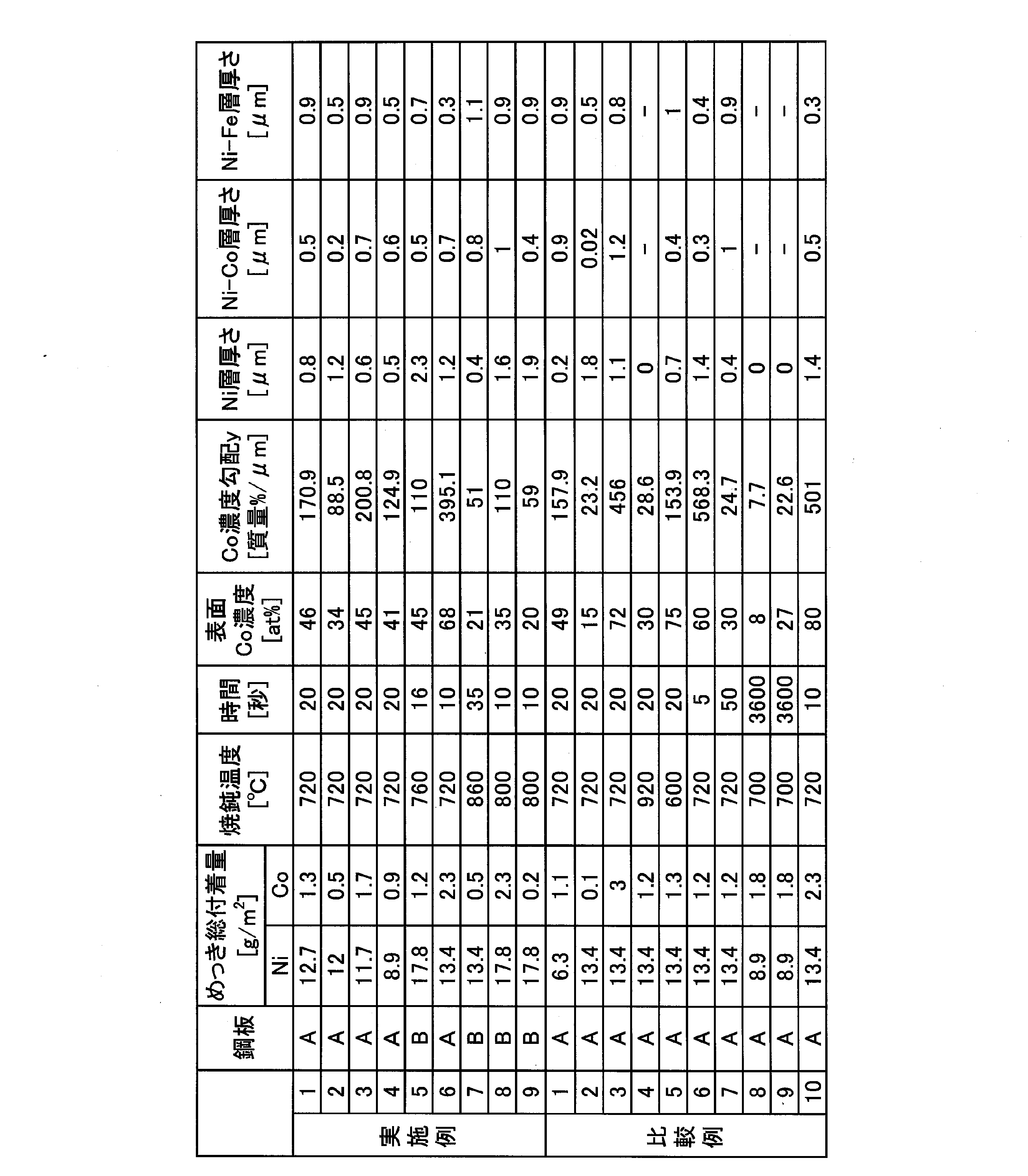
Ni及びCoの総付着量、Ni-Co合金めっき層の表面のCoの原子濃度(表面Co濃度)、Co濃度勾配、及びNi層厚さを本発明に従って製造した実施例1~9は、電池性能、加工性共に良好な結果であった。
一方で、Niの総付着量が少ない比較例1は、Ni層厚さが薄く、めっき層表層までFeが拡散していた。そのため比較例1は加工性に劣った。
比較例2及び3は、Coの総付着量が範囲外のため、表面Co濃度が発明範囲外となり、かつCo濃度勾配も発明範囲外となった。このため、比較例2及び3は、電池性能、加工性共に劣った。
比較例4は焼鈍温度が高すぎるためにCo及びFeの拡散が過剰に進み、Ni層が形成されず、加工性に劣った。逆に比較例5は焼鈍温度が低すぎるため表面Co濃度が高く、耐漏液性に劣った。
比較例6及び7は、焼鈍時間が上述の好ましい範囲外のため、Co濃度勾配が発明範囲外となり、加工性に劣った。
比較例8及び9は、BAF焼鈍のためCo及びFeの拡散が過剰に進行し、Ni層が欠乏し、めっき層の表層にFeが拡散した。そのため、めっき層中のCoの深さ方向の濃度勾配yが低く、Ni層も形成しないため、比較例8及び9は加工性に劣った。なお、表2のNi-Co合金めっき層の厚さの欄、及びNi-Fe合金層の厚さの欄における“―”は、Ni-Fe-Coの3元系の合金層が、少なくとも一部に混在した状態であったので、Ni-Co合金めっき層とNi-Fe合金層とを区別できず、これらの厚さが測定できなかったことを示す。
比較例10は、表面Co濃度、及びCo濃度勾配の両方が発明範囲外となり、耐漏液性、加工性共に劣った。これは、めっき浴の組成が不適切であったので、合金化処理前のめっき層の歪の量が小さかったことによると推定される。

2…めっき層
3…Ni-Fe合金層
4…Ni層
5…Ni-Co合金めっき層
10…表面処理鋼板
Claims (7)
- 鋼板母材と、
前記鋼板母材の表面に設けられた、Ni、Co、Fe及び不純物からなるめっき層と、
を備える表面処理鋼板であって、
前記めっき層は、
前記めっき層の断面を、前記表面処理鋼板の表面から前記鋼板母材に向かってエネルギー分散型X線分析法で線分析することにより特定される、Coの質量濃度が最大となる位置と、Coの質量濃度が初めて8質量%となる位置との間の領域であるNi-Co合金めっき層と、
前記めっき層の前記断面を、前記表面処理鋼板の前記表面から前記鋼板母材に向かって前記エネルギー分散型X線分析法で前記線分析することにより特定される、Feの質量濃度が初めて8質量%になる位置と、Niの質量濃度と前記Feの質量濃度とが初めて同一となる位置との間の領域であるNi-Fe合金層と、
前記Ni-Co合金めっき層と前記Ni-Fe合金層との間に存在するNi層と、
を含み、
前記めっき層において、Coの総付着量が0.2~2.3g/m2であり、Niの総付着量が8.9g/m2以上であり、
前記Ni層は、0.3~3.0μmの厚さを有し、
前記Ni-Co合金めっき層の表面をX線光電分光法で分析することにより特定されるCoの原子濃度が20~70at%であり、
前記めっき層の前記断面を前記エネルギー分散型X線分析法で前記線分析することにより特定されるIp、I1/5、及びΔxを下記式(1)に代入することで得られる、前記めっき層中のCoの深さ方向の濃度勾配yが50~400質量%/μmである
ことを特徴とする表面処理鋼板。
y=(Ip-I1/5)/(Δx)・・・(1)
ここで、
Ip:前記線分析により特定される、Coのピーク質量濃度、
I1/5:Ipの1/5の質量濃度、
Δx=X1/5-Xp、
Xp:前記線分析により特定される、Coの質量濃度がIpである位置の単位μmでの深さ、
X1/5:前記線分析により特定される、Xpよりも前記鋼板母材の側でCoの質量濃度が最初にI1/5となる位置の単位μmでの深さ
であり、X1/5、Xpともに深さ測定の原点を前記めっき層の表面とする。 - 前記めっき層において、Coの前記総付着量が0.4g/m2以上であることを特徴とする請求項1に記載の表面処理鋼板。
- 前記Ni層の前記厚さが2.0μm以下であることを特徴とする請求項1又は2に記載の表面処理鋼板。
- 前記めっき層において、Coの前記総付着量が0.4~1.8g/m2であることを特徴とする請求項1~3のいずれか一項に記載の表面処理鋼板。
- 前記めっき層において、Niの前記総付着量が9.5~17g/m2であることを特徴とする請求項1~4のいずれか一項に記載の表面処理鋼板。
- 前記Ni-Co合金めっき層の前記表面におけるCoの前記原子濃度が30~60at%であることを特徴とする請求項1~5のいずれか一項に記載の表面処理鋼板。
- 前記めっき層中のCoの前記深さ方向の前記濃度勾配yが110~300であることを特徴とする請求項1~6のいずれか一項に記載の表面処理鋼板。
Priority Applications (6)
| Application Number | Priority Date | Filing Date | Title |
|---|---|---|---|
| JP2018533285A JP6394847B1 (ja) | 2017-03-02 | 2018-03-01 | 表面処理鋼板 |
| US16/489,652 US11084252B2 (en) | 2017-03-02 | 2018-03-01 | Surface-treated steel sheet |
| CN201880014706.XA CN110366610B (zh) | 2017-03-02 | 2018-03-01 | 表面处理钢板 |
| KR1020197025231A KR102304252B1 (ko) | 2017-03-02 | 2018-03-01 | 표면 처리 강판 |
| SG11201907947VA SG11201907947VA (en) | 2017-03-02 | 2018-03-01 | Surface-treated steel sheet |
| EP18760695.9A EP3591098A4 (en) | 2017-03-02 | 2018-03-01 | SURFACE TREATED STEEL SHEET |
Applications Claiming Priority (2)
| Application Number | Priority Date | Filing Date | Title |
|---|---|---|---|
| JP2017038958 | 2017-03-02 | ||
| JP2017-038958 | 2017-03-02 |
Publications (1)
| Publication Number | Publication Date |
|---|---|
| WO2018159760A1 true WO2018159760A1 (ja) | 2018-09-07 |
Family
ID=63370508
Family Applications (1)
| Application Number | Title | Priority Date | Filing Date |
|---|---|---|---|
| PCT/JP2018/007782 WO2018159760A1 (ja) | 2017-03-02 | 2018-03-01 | 表面処理鋼板 |
Country Status (7)
| Country | Link |
|---|---|
| US (1) | US11084252B2 (ja) |
| EP (1) | EP3591098A4 (ja) |
| JP (1) | JP6394847B1 (ja) |
| KR (1) | KR102304252B1 (ja) |
| CN (1) | CN110366610B (ja) |
| SG (1) | SG11201907947VA (ja) |
| WO (1) | WO2018159760A1 (ja) |
Cited By (6)
| Publication number | Priority date | Publication date | Assignee | Title |
|---|---|---|---|---|
| WO2019159794A1 (ja) * | 2018-02-14 | 2019-08-22 | 日本製鉄株式会社 | 電池容器用表面処理鋼板及び電池容器用表面処理鋼板の製造方法 |
| WO2020009213A1 (ja) * | 2018-07-06 | 2020-01-09 | 日本製鉄株式会社 | 表面処理鋼板および表面処理鋼板の製造方法 |
| WO2020009212A1 (ja) * | 2018-07-06 | 2020-01-09 | 日本製鉄株式会社 | 表面処理鋼板および表面処理鋼板の製造方法 |
| WO2022118769A1 (ja) | 2020-12-03 | 2022-06-09 | 日本製鉄株式会社 | 表面処理鋼板 |
| KR20230113602A (ko) | 2020-12-03 | 2023-07-31 | 닛폰세이테츠 가부시키가이샤 | 표면 처리 강판 |
| JP7425298B2 (ja) | 2020-03-03 | 2024-01-31 | 日本製鉄株式会社 | 電池缶用Niめっき鋼板、及びその製造方法 |
Families Citing this family (3)
| Publication number | Priority date | Publication date | Assignee | Title |
|---|---|---|---|---|
| WO2018181950A1 (ja) * | 2017-03-31 | 2018-10-04 | 東洋鋼鈑株式会社 | 表面処理金属板、電池容器および電池 |
| US11773503B2 (en) * | 2019-12-20 | 2023-10-03 | Nippon Steel Corporation | Ni-plated steel sheet and method for manufacturing Ni-plated steel sheet |
| JP7060186B1 (ja) * | 2020-12-03 | 2022-04-26 | 日本製鉄株式会社 | 表面処理鋼板 |
Citations (7)
| Publication number | Priority date | Publication date | Assignee | Title |
|---|---|---|---|---|
| JPH0317916B2 (ja) | 1987-08-10 | 1991-03-11 | Hire Unto Myureru | |
| JP2009129664A (ja) | 2007-11-22 | 2009-06-11 | Fdk Energy Co Ltd | アルカリ電池用正極缶、アルカリ電池及びその製造方法 |
| WO2010113502A1 (ja) * | 2009-03-31 | 2010-10-07 | 新日本製鐵株式会社 | 非水電解質を用いた二次電池の金属外装ケース用素材及び金属外装ケース、二次電池、金属外装ケース用素材の製造方法 |
| JP2012048958A (ja) | 2010-08-26 | 2012-03-08 | Fdk Energy Co Ltd | アルカリ電池 |
| WO2012147843A1 (ja) | 2011-04-28 | 2012-11-01 | 東洋鋼鈑株式会社 | 電池容器用表面処理鋼板、電池容器および電池 |
| JP2015076151A (ja) * | 2013-10-07 | 2015-04-20 | パナソニックIpマネジメント株式会社 | アルカリ乾電池 |
| JP2017038958A (ja) | 2016-11-16 | 2017-02-23 | 富士フイルム株式会社 | 内視鏡装置 |
Family Cites Families (13)
| Publication number | Priority date | Publication date | Assignee | Title |
|---|---|---|---|---|
| JPH0317916Y2 (ja) | 1986-12-02 | 1991-04-16 | ||
| CN1127158C (zh) * | 1996-09-03 | 2003-11-05 | 东洋钢钣株式会社 | 用于电池外壳的表面处理钢板、电池外壳和使用该外壳的电池 |
| EP1352993B1 (en) * | 2001-01-19 | 2011-05-11 | The Furukawa Electric Co., Ltd. | A method for preparation of metal-plated material |
| DE10129900C1 (de) * | 2001-06-21 | 2003-02-13 | Hille & Mueller Gmbh | Verfahren zur Wärmebehandlung eines Kaltbandes mit einer Oberflächenbeschichtung aus Ni und/oder Co, durch das Verfahren herstellbares Blech und durch das Verfahren herstellbarer Batteriebecher |
| KR100696929B1 (ko) * | 2002-04-22 | 2007-03-20 | 도요 고한 가부시키가이샤 | 전지 케이스용 표면 처리 강판, 전지 케이스 및 그것을사용한 전지 |
| JP3840430B2 (ja) * | 2002-05-16 | 2006-11-01 | 東洋鋼鈑株式会社 | 電池ケース用表面処理鋼板及び電池ケース |
| JP5168237B2 (ja) * | 2009-06-29 | 2013-03-21 | 新日鐵住金株式会社 | NiおよびFeの溶出が抑制された高容量リチウムイオン電池の金属外装ケース用素材および金属外装ケースならびにリチウムイオン電池 |
| JP5570078B2 (ja) * | 2009-06-09 | 2014-08-13 | 東洋鋼鈑株式会社 | Niめっき鋼板及びそのNiめっき鋼板を用いた電池缶の製造方法 |
| KR101699112B1 (ko) * | 2010-01-08 | 2017-01-23 | 도요 고한 가부시키가이샤 | 프레스성이 우수한 전지 캔용 Ni 도금 강판 |
| CN102822387B (zh) * | 2010-03-25 | 2014-12-31 | 新日铁住金株式会社 | 耐蚀性优异的容器用钢板 |
| US9017862B2 (en) * | 2011-07-07 | 2015-04-28 | Toyo Kohan Co., Ltd. | Surface-treated steel sheet for battery cases, method of producing same, battery case, and battery |
| JP6033304B2 (ja) * | 2012-07-03 | 2016-11-30 | 東洋鋼鈑株式会社 | 電池容器用表面処理鋼板、電池容器および電池 |
| TWI488733B (zh) * | 2012-10-04 | 2015-06-21 | Jx Nippon Mining & Metals Corp | Metal material for electronic parts and manufacturing method thereof |
-
2018
- 2018-03-01 EP EP18760695.9A patent/EP3591098A4/en active Pending
- 2018-03-01 JP JP2018533285A patent/JP6394847B1/ja active Active
- 2018-03-01 CN CN201880014706.XA patent/CN110366610B/zh active Active
- 2018-03-01 KR KR1020197025231A patent/KR102304252B1/ko active IP Right Grant
- 2018-03-01 WO PCT/JP2018/007782 patent/WO2018159760A1/ja unknown
- 2018-03-01 US US16/489,652 patent/US11084252B2/en active Active
- 2018-03-01 SG SG11201907947VA patent/SG11201907947VA/en unknown
Patent Citations (7)
| Publication number | Priority date | Publication date | Assignee | Title |
|---|---|---|---|---|
| JPH0317916B2 (ja) | 1987-08-10 | 1991-03-11 | Hire Unto Myureru | |
| JP2009129664A (ja) | 2007-11-22 | 2009-06-11 | Fdk Energy Co Ltd | アルカリ電池用正極缶、アルカリ電池及びその製造方法 |
| WO2010113502A1 (ja) * | 2009-03-31 | 2010-10-07 | 新日本製鐵株式会社 | 非水電解質を用いた二次電池の金属外装ケース用素材及び金属外装ケース、二次電池、金属外装ケース用素材の製造方法 |
| JP2012048958A (ja) | 2010-08-26 | 2012-03-08 | Fdk Energy Co Ltd | アルカリ電池 |
| WO2012147843A1 (ja) | 2011-04-28 | 2012-11-01 | 東洋鋼鈑株式会社 | 電池容器用表面処理鋼板、電池容器および電池 |
| JP2015076151A (ja) * | 2013-10-07 | 2015-04-20 | パナソニックIpマネジメント株式会社 | アルカリ乾電池 |
| JP2017038958A (ja) | 2016-11-16 | 2017-02-23 | 富士フイルム株式会社 | 内視鏡装置 |
Non-Patent Citations (2)
| Title |
|---|
| PETER, LASZLO ET AL.: "On the composition depth profile of electrodeposited Fe-Co-Ni alloys", ELECTROCHIMICA ACTA, vol. 55, no. 16, 2 April 2010 (2010-04-02), pages 4734 - 4741, XP055554452, Retrieved from the Internet <URL:https://doi.org/10.1016/j.electacta.2010.03.075> * |
| See also references of EP3591098A4 |
Cited By (6)
| Publication number | Priority date | Publication date | Assignee | Title |
|---|---|---|---|---|
| WO2019159794A1 (ja) * | 2018-02-14 | 2019-08-22 | 日本製鉄株式会社 | 電池容器用表面処理鋼板及び電池容器用表面処理鋼板の製造方法 |
| WO2020009213A1 (ja) * | 2018-07-06 | 2020-01-09 | 日本製鉄株式会社 | 表面処理鋼板および表面処理鋼板の製造方法 |
| WO2020009212A1 (ja) * | 2018-07-06 | 2020-01-09 | 日本製鉄株式会社 | 表面処理鋼板および表面処理鋼板の製造方法 |
| JP7425298B2 (ja) | 2020-03-03 | 2024-01-31 | 日本製鉄株式会社 | 電池缶用Niめっき鋼板、及びその製造方法 |
| WO2022118769A1 (ja) | 2020-12-03 | 2022-06-09 | 日本製鉄株式会社 | 表面処理鋼板 |
| KR20230113602A (ko) | 2020-12-03 | 2023-07-31 | 닛폰세이테츠 가부시키가이샤 | 표면 처리 강판 |
Also Published As
| Publication number | Publication date |
|---|---|
| CN110366610A (zh) | 2019-10-22 |
| EP3591098A1 (en) | 2020-01-08 |
| KR102304252B1 (ko) | 2021-09-23 |
| CN110366610B (zh) | 2021-06-29 |
| SG11201907947VA (en) | 2019-09-27 |
| JPWO2018159760A1 (ja) | 2019-03-07 |
| JP6394847B1 (ja) | 2018-09-26 |
| EP3591098A4 (en) | 2021-01-27 |
| US11084252B2 (en) | 2021-08-10 |
| KR20190112080A (ko) | 2019-10-02 |
| US20190381765A1 (en) | 2019-12-19 |
Similar Documents
| Publication | Publication Date | Title |
|---|---|---|
| JP6394847B1 (ja) | 表面処理鋼板 | |
| JP6669321B2 (ja) | 電池容器用表面処理鋼板及び電池容器用表面処理鋼板の製造方法 | |
| EP3385410A1 (en) | Surface-treated steel plate for cell container | |
| EP1191615B1 (en) | A method for manufacturing a surface treated steel sheet to be formed into a battery container | |
| US11242591B2 (en) | Surface-treated metal plate, cell container, and cell | |
| JP6729821B2 (ja) | 表面処理鋼板および表面処理鋼板の製造方法 | |
| US9132610B2 (en) | Ni-containing-surface-treated steel sheet for can and manufacturing method thereof | |
| CN112368426B (zh) | 表面处理钢板以及表面处理钢板的制造方法 | |
| US11618965B2 (en) | Ni-plated steel sheet and method for manufacturing Ni-plated steel sheet | |
| TWI477662B (zh) | 鍍錫鋼板之製造方法及鍍錫鋼板暨化學轉化處理液 | |
| KR20160037845A (ko) | 전지 용기용 표면 처리 강판, 전지 용기 및 전지 | |
| JP3272866B2 (ja) | アルカリ電池ケース用表面処理鋼板、アルカリ電池ケースおよびアルカリ電池 | |
| JP4452198B2 (ja) | シーム溶接性に優れた表面処理鋼板 | |
| WO2021192614A1 (ja) | Sn系めっき鋼板 | |
| JP6048441B2 (ja) | 容器用鋼板 | |
| CN116601337A (zh) | 表面处理钢板及其制造方法 | |
| JP2015140468A (ja) | 容器用鋼板およびその製造方法 |
Legal Events
| Date | Code | Title | Description |
|---|---|---|---|
| ENP | Entry into the national phase |
Ref document number: 2018533285 Country of ref document: JP Kind code of ref document: A |
|
| 121 | Ep: the epo has been informed by wipo that ep was designated in this application |
Ref document number: 18760695 Country of ref document: EP Kind code of ref document: A1 |
|
| ENP | Entry into the national phase |
Ref document number: 20197025231 Country of ref document: KR Kind code of ref document: A |
|
| NENP | Non-entry into the national phase |
Ref country code: DE |
|
| ENP | Entry into the national phase |
Ref document number: 2018760695 Country of ref document: EP Effective date: 20191002 |