WO2018159503A1 - リアクトル - Google Patents
リアクトル Download PDFInfo
- Publication number
- WO2018159503A1 WO2018159503A1 PCT/JP2018/006785 JP2018006785W WO2018159503A1 WO 2018159503 A1 WO2018159503 A1 WO 2018159503A1 JP 2018006785 W JP2018006785 W JP 2018006785W WO 2018159503 A1 WO2018159503 A1 WO 2018159503A1
- Authority
- WO
- WIPO (PCT)
- Prior art keywords
- case
- core
- winding
- reactor
- coil
- Prior art date
- Legal status (The legal status is an assumption and is not a legal conclusion. Google has not performed a legal analysis and makes no representation as to the accuracy of the status listed.)
- Ceased
Links
Images


Classifications
-
- H—ELECTRICITY
- H01—ELECTRIC ELEMENTS
- H01F—MAGNETS; INDUCTANCES; TRANSFORMERS; SELECTION OF MATERIALS FOR THEIR MAGNETIC PROPERTIES
- H01F27/00—Details of transformers or inductances, in general
- H01F27/02—Casings
-
- H—ELECTRICITY
- H01—ELECTRIC ELEMENTS
- H01F—MAGNETS; INDUCTANCES; TRANSFORMERS; SELECTION OF MATERIALS FOR THEIR MAGNETIC PROPERTIES
- H01F27/00—Details of transformers or inductances, in general
- H01F27/02—Casings
- H01F27/022—Encapsulation
-
- H—ELECTRICITY
- H01—ELECTRIC ELEMENTS
- H01F—MAGNETS; INDUCTANCES; TRANSFORMERS; SELECTION OF MATERIALS FOR THEIR MAGNETIC PROPERTIES
- H01F27/00—Details of transformers or inductances, in general
- H01F27/02—Casings
- H01F27/025—Constructional details relating to cooling
-
- H—ELECTRICITY
- H01—ELECTRIC ELEMENTS
- H01F—MAGNETS; INDUCTANCES; TRANSFORMERS; SELECTION OF MATERIALS FOR THEIR MAGNETIC PROPERTIES
- H01F27/00—Details of transformers or inductances, in general
- H01F27/24—Magnetic cores
-
- H—ELECTRICITY
- H01—ELECTRIC ELEMENTS
- H01F—MAGNETS; INDUCTANCES; TRANSFORMERS; SELECTION OF MATERIALS FOR THEIR MAGNETIC PROPERTIES
- H01F27/00—Details of transformers or inductances, in general
- H01F27/28—Coils; Windings; Conductive connections
- H01F27/30—Fastening or clamping coils, windings, or parts thereof together; Fastening or mounting coils or windings on core, casing, or other support
- H01F27/306—Fastening or mounting coils or windings on core, casing or other support
-
- H—ELECTRICITY
- H01—ELECTRIC ELEMENTS
- H01F—MAGNETS; INDUCTANCES; TRANSFORMERS; SELECTION OF MATERIALS FOR THEIR MAGNETIC PROPERTIES
- H01F27/00—Details of transformers or inductances, in general
- H01F27/28—Coils; Windings; Conductive connections
- H01F27/32—Insulating of coils, windings, or parts thereof
- H01F27/324—Insulation between coil and core, between different winding sections, around the coil; Other insulation structures
-
- H—ELECTRICITY
- H01—ELECTRIC ELEMENTS
- H01F—MAGNETS; INDUCTANCES; TRANSFORMERS; SELECTION OF MATERIALS FOR THEIR MAGNETIC PROPERTIES
- H01F41/00—Apparatus or processes specially adapted for manufacturing or assembling magnets, inductances or transformers; Apparatus or processes specially adapted for manufacturing materials characterised by their magnetic properties
- H01F41/02—Apparatus or processes specially adapted for manufacturing or assembling magnets, inductances or transformers; Apparatus or processes specially adapted for manufacturing materials characterised by their magnetic properties for manufacturing cores, coils, or magnets
- H01F41/0206—Manufacturing of magnetic cores by mechanical means
- H01F41/0246—Manufacturing of magnetic circuits by moulding or by pressing powder
-
- H—ELECTRICITY
- H01—ELECTRIC ELEMENTS
- H01F—MAGNETS; INDUCTANCES; TRANSFORMERS; SELECTION OF MATERIALS FOR THEIR MAGNETIC PROPERTIES
- H01F37/00—Fixed inductances not covered by group H01F17/00
Definitions
- the present invention relates to a reactor.
- This application claims priority based on Japanese Patent Application No. 2017-041148 filed on Mar. 3, 2017, and incorporates all the contents described in the aforementioned Japanese application.
- Patent Document 1 discloses a reactor that includes a coil having a pair of winding portions arranged in parallel and a magnetic core that forms a closed magnetic circuit, and is used as a component of a converter of a hybrid vehicle.
- the magnetic core can be divided into an inner core portion disposed inside the winding portion and an outer core portion disposed outside the winding portion.
- the coil / magnetic core combination is housed inside the case.
- the reactor of the present disclosure is A coil having a pair of windings arranged in parallel; A magnetic core having an inner core portion disposed inside the winding portion and an outer core portion exposed from the winding portion; A case for storing a combination of the coil and the magnetic core; A reactor comprising: The case is A bottom plate portion on which the assembly is placed; A side wall portion erected from the bottom plate portion, The side wall includes a core notch that exposes at least a part of the outer core to the outside of the case.
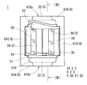
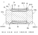
- FIG. 3 is a sectional view taken along line III-III in FIG.
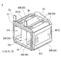
- FIG. 3 is a perspective view of a coil molded body provided in the reactor according to the first embodiment. It is a perspective view of the reactor of Embodiment 2. It is a schematic top view of the reactor of Embodiment 3. It is a schematic top view of the reactor of Embodiment 4.
- the case serves to physically protect the combination and is also used to fix the reactor to the installation target.
- the reactor of Patent Document 1 has a problem that the entire circumference of the assembly is surrounded by the case, and the heat dissipation from the assembly to the outside is not good.
- This disclosure is intended to provide a reactor having a case and excellent heat dissipation.
- the reactor according to the embodiment is A coil having a pair of windings arranged in parallel; A magnetic core having an inner core portion disposed inside the winding portion and an outer core portion exposed from the winding portion; A case for storing a combination of the coil and the magnetic core; A reactor comprising: The case is A bottom plate portion on which the assembly is placed; A side wall portion erected from the bottom plate portion, The side wall includes a core notch that exposes at least a part of the outer core to the outside of the case.
- the reactor may be operated under conditions that increase the loss in the magnetic core.
- the heat generated in the magnetic core may exceed the heat generated in the coil, and if the outer periphery of the magnetic core is surrounded by the case, the reactor may be heated and the operation of the reactor may become unstable.
- the notch portion for the core that exposes a part of the outer core portion to the outside of the case is provided on the side wall portion of the case. It becomes easy to be discharged outside. As a result, the heat dissipation of the reactor according to the embodiment is improved, and the operation of the reactor is stabilized.
- the stress for fixing the reactor to the installation target can hardly act on the assembly in the case.
- the case may receive the tightening force of the mounting bracket. it can.
- a fixing portion having a screw hole is formed in a part of the case and the fixing portion is screwed to the installation target, the case can receive the tightening force of the screw. In any case, stress does not act directly on the combination in the case.
- the core notch is a through hole communicating with the inside and outside of the side wall, A form in which a part of the outer core portion is held in a state of being fitted into the through hole can be exemplified.
- the said baseplate part can mention the form provided with the bottom hole part which exposes at least one part of the said outer core part to the downward direction of the said case.
- the outer core portion is composed of a composite material including soft magnetic powder and resin, The form which at least one part of the said outer core part has joined to the internal peripheral surface of the said case can be mentioned.
- the composite material has an advantage that the magnetic properties can be easily adjusted by adjusting the amount of the soft magnetic powder. Moreover, since the composite material can be produced by filling the case with the composite material, the productivity of the reactor can be improved.
- the composite material is filled in a case to produce a magnetic core, the magnetic core is joined to the inner peripheral surface of the case, and heat is easily transmitted from the magnetic core to the case. As a result, heat is easily released to the outside of the case through the case.
- the side wall portion has an outer side surface in the parallel direction in one of the winding portions, or an outer side surface in the parallel direction in the other winding portion, when a direction in which the winding portions are arranged in parallel is a parallel direction.
- the form provided with the notch part for coils exposed to the outward of the said case can be mentioned.
- the outer surface of one winding part is exposed from the case, so that the heat dissipation of the reactor can be further improved.
- the side wall portion includes an outer side surface in the parallel direction in one of the winding portions and an outer side surface in the parallel direction in the other winding portion, where the direction in which the winding portions are arranged in parallel is a parallel direction.
- the form provided with the notch part for coils exposed to the outward of the said case, respectively can be mentioned.
- the heat radiation performance of the reactor can be further improved by adopting a configuration in which the outer surfaces of both winding portions are exposed from the case.
- the heat radiation from the coil can be promoted by arranging the heat dissipating member in the portion of the winding part exposed from the notch for the coil.
- the heat radiating member include a heat radiating fin attached via a heat radiating grease or a heat radiating sheet, an attachment member for fixing the reactor to the installation target, and the like.
- the exposed portion of the winding portion can be directly attached to the installation target without using an attachment member. In that case, it is good to interpose a thermal radiation grease and a thermal radiation sheet as a thermal radiation member between the exposed part of a winding part, and installation object.
- the heat radiation from the outer core portion can be promoted by disposing the heat radiating member in the portion of the outer core portion exposed from the core cutout portion.
- the thermal conductivity of the magnetic core of the composite material of the soft magnetic powder is lower by an order of magnitude compared to the magnetic core of the green compact formed by pressing the soft magnetic powder.
- the content is 70% by volume, it is around 3 W / m ⁇ K. Therefore, in particular, when the outer core portion is made of a composite material, it is preferable to provide a heat dissipation member at the exposed portion of the outer core portion.
- the coil includes an integrated resin made of an insulating resin,
- the integrated resin is A turn covering portion for integrating the turns of the winding portion;
- coated part interposed between the end surface of the said winding part and the said outer core part can be mentioned.
- each turn of the coil By integrating each turn of the coil with the integrated resin turn coating part, when the composite material is filled inside the winding part in manufacturing the reactor, the leakage of the composite material from between the turns of the winding part is prevented. Can be suppressed. Moreover, the insulation between the end surface of a winding part and an outer core part is securable by the end surface coating
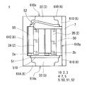
- a reactor 1 shown in FIG. 1 includes a combined body 10 of a coil 2 and a magnetic core 3 and a case 6 that houses the combined body 10.
- One of the features of the reactor 1 is that a part of the magnetic core 3 is exposed to the outside of the case 6 from the core notches 61Ax and 61Bx provided in the case 6.
- each structure with which the reactor 1 is provided is demonstrated in detail, and the manufacturing method of the reactor 1 is demonstrated then.
- the coil 2 of the present embodiment includes a pair of winding portions 2A and 2B and a connecting portion 2R (FIG. 3) that connects both the winding portions 2A and 2B.
- the winding portions 2A and 2B provided in the coil 2 of this example are portions in which the windings are spirally wound, are formed in a hollow cylindrical shape with the same number of turns and the same winding direction, and the respective axial directions are parallel. It is paralleled to become. The number of turns and the cross-sectional area of the winding may be different in each winding part 2A, 2B.
- the coil 2 is manufactured with one coil
- Each winding part 2A, 2B of this embodiment is formed in a rectangular tube shape.
- the rectangular tube-shaped winding parts 2A and 2B are winding parts whose end face shape is a square shape (including a square shape) with rounded corners.
- the winding portions 2A and 2B may be formed in a cylindrical shape.
- the cylindrical winding portion is a winding portion whose end face shape is a closed curved surface shape (an elliptical shape, a perfect circle shape, a race track shape, etc.).
- the coil 2 including the winding portions 2A and 2B is a coated wire having an insulating coating made of an insulating material on the outer periphery of a conductor such as a flat wire or a round wire made of a conductive material such as copper, aluminum, magnesium, or an alloy thereof.
- a conductor such as a flat wire or a round wire made of a conductive material such as copper, aluminum, magnesium, or an alloy thereof.
- the conductor is made of a copper rectangular wire (winding)
- the insulating coating is made of enamel (typically polyimide resin) by edgewise winding, whereby each winding portion 2A, 2B is formed.
- Both end portions 2a and 2b of the coil 2 are extended from the winding portions 2A and 2B and connected to a terminal member (not shown).
- the insulating coating such as enamel is peeled off at both ends 2a and 2b.
- An external device such as a power source for supplying power is connected to the coil 2 through the terminal member.
- the coil 2 of this example is used in the form of a coil molded body 4 including an integrated resin 5 that is integrated so that the turns of the winding portions 2A and 2B are not separated.
- the integrated resin 5 has a function of suppressing the expansion of the winding portions 2A and 2B and a function of ensuring insulation between the coil 2 and the magnetic core 3 (FIG. 1).
- Examples of the integrated resin 5 include polyphenylene sulfide (PPS) resin, polytetrafluoroethylene (PTFE) resin, liquid crystal polymer (LCP), polyamide (PA) resin such as nylon 6 and nylon 66, and polybutylene terephthalate (PBT) resin.
- thermoplastic resin such as acrylonitrile / butadiene / styrene (ABS) resin.
- the integrated resin can be formed of a thermosetting resin such as an unsaturated polyester resin, an epoxy resin, a urethane resin, or a silicone resin.
- a ceramic filler may be included in the resin to improve the heat dissipation of the integrated resin 5.
- the ceramic filler for example, nonmagnetic powders such as alumina, silica, boron nitride, and aluminum nitride can be used.
- the integrated resin 5 of this example is composed of a turn covering portion 50 for integrating the turns of the winding portions 2A and 2B, and an end surface covering interposed between the end surfaces of the winding portions 2A and 2B and the outer core portion 32. Part 51. Further, the integrated resin 5 includes a connecting portion covering portion 52 that covers the connecting portion 2R (FIG. 3) of the winding portions 2A and 2B.
- the turn covering portion 50 includes an inner peripheral covering portion 50A that covers the inner peripheral surfaces of the winding portions 2A and 2B, and an outer peripheral covering portion 50B that covers at least a part of the outer peripheral surfaces of the winding portions 2A and 2B. (Fig. 4).
- the inner periphery covering portion 50A covers the entire inner peripheral surface of the winding portions 2A and 2B, suppresses the expansion of the winding portions 2A and 2B, and the winding portions 2A and 2B and the inner core disposed therein. The insulation between the part 31 (FIG. 3) is ensured.
- the outer periphery covering portion 50B covers the four corners formed by bending the winding, of the outer peripheral surfaces of the winding portions 2A and 2B, and suppresses the expansion of the winding portions 2A and 2B.
- the outer peripheral covering portion 50B is not formed in the flat portion where the winding is not bent, and is exposed to the outside of the integrated resin 5. The heat radiation from the outer surfaces of the portions 2A and 2B is not hindered by the outer periphery covering portion 50B.
- the end face covering portion 51 is provided so as to connect the turn covering portion 50 of the winding portion 2A and the turn covering portion 50 of the winding portion 2B.
- the end surface covering portion 51 is provided with a pair of through holes 51h and 51h communicating with the inside of the winding portions 2A and 2B.
- the inner core portion 31 (FIG. 3) is disposed inside the winding portions 2A and 2B through the through hole 51h.
- the end surface covering portion 51 has a frame portion 510 that protrudes in a frame shape toward the side away from the coil 2 in the axial direction of the winding portions 2A and 2B.
- the outer surface of the frame portion 510 (the surface in the parallel direction of the winding portions 2A and 2B) is in contact with the step between the coil facing walls 61C and 61D of the case 6 (see FIGS. 1 and 2).
- the frame portion 510 has a function of suppressing the leakage of the composite material when the coil 2 is positioned in the case 6 and the reactor 1 is manufactured.
- the integrated resin 5 for example, a fusion layer in which a coating layer of a heat-fusible resin is formed on the outer periphery of a winding (further outer periphery of an insulating coating such as enamel) and the coating layers are heat-sealed.
- the form of resin can be mentioned.
- the integrated resin 5 can be made very thin, for example, 1 mm or less, and further 100 ⁇ m or less, the heat dissipation of the coil 2 can be improved.
- the winding portions 2A and 2B can be individually integrated, it is possible to easily release the heat of the coil 2 from between the winding portions 2A and 2B.
- a heat radiating member can be arranged between the winding parts 2A and 2B, and various sensors for measuring the temperature of the coil 2 can be arranged.
- the integrated resin 5 made of the fusion resin is very thin, even if each turn of the winding portions 2A and 2B is integrated with the integrated resin 5, the shape of the turns of the winding portions 2A and 2B , Turn boundaries are visible from the outside.
- a thermosetting resin such as an epoxy resin, a silicone resin, or an unsaturated polyester can be used.
- the magnetic core 3 is a magnetic body made of a powder compact or a composite material. As shown in FIG. 3, for convenience, the magnetic core 3 includes an inner core portion 31 disposed inside the winding portions 2A and 2B, an outer core portion 32 disposed outside the winding portions 2A and 2B, Can be divided into The inner core portion 31 and the outer core portion 32 may be made of different materials, or may be made of the same material. As an example of the former, the inner core part 31 is made of a green compact and the outer core part 32 is made of a composite material. As the latter example, the inner core part 31 and the outer core part 32 are made of a composite material. Is mentioned. In this example, the core portions 31 and 32 are integrally formed of a composite material.
- the composite material is a magnetic body containing soft magnetic powder and resin.
- the soft magnetic powder is an aggregate of magnetic particles composed of an iron group metal such as iron or an alloy thereof (Fe—Si alloy, Fe—Si—Al alloy, Fe—Ni alloy, etc.).
- An insulating coating such as phosphate may be formed on the surface of the magnetic particles.
- the resin for example, thermosetting resin such as epoxy resin, phenol resin, silicone resin, urethane resin, PA resin such as PPS resin, nylon 6, nylon 66, thermoplastic resin such as polyimide resin, fluorine resin, etc. are used. it can.
- the composite material may contain a filler or the like.
- a compacting body is a magnetic body formed by pressure-molding raw material powder containing soft magnetic powder.
- the outer core portion 32 may be composed of a composite material, and the inner core portion 31 may be composed of a powder compact.
- the inner core part 31 may be configured by a single compacted body, or the inner core part 31 may be configured by alternately connecting the core pieces and the gap plate of the compacted body.
- the gap plate is a plate made of a nonmagnetic material such as alumina.
- the outer core portion 32 of the present example is formed by injection molding or filling a composite material into the case 6 after the coil molded body 4 is accommodated in the case 6 as shown in a reactor manufacturing method described later. It is formed. Therefore, the outer core portion 32 of the magnetic core 3 is joined to the inner peripheral surface of the case 6.
- a part of the outer core part 32, in this example, part of the end face in the axial direction of the winding parts 2A, 2B is a core notch part 61Ax, 61Bx (see FIG. 1, FIG. 2) to the outside of the case 6.
- the outer peripheral surface of the outer core portion 32 exposed from the case 6 is flush with the outer peripheral surface of the side wall portion 61 of the case 6.
- a heat radiating member such as a heat radiating fin can be provided on the exposed portion of the outer core portion 32.
- a heat radiating grease or a heat radiating sheet may be interposed between the heat radiating fins and the outer core portion 32.
- the case 6 includes a bottom plate portion 60 and a side wall portion 61.
- the bottom plate portion 60 and the side wall portion 61 may be integrally formed, or the separately prepared bottom plate portion 60 and the side wall portion 61 may be connected.
- a material of the case 6, for example, aluminum or an alloy thereof, a nonmagnetic metal such as magnesium or an alloy thereof, or a resin can be used. If the bottom plate portion 60 and the side wall portion 61 are separated, the materials of the two 60 and 61 can be different.
- the bottom plate portion 60 is made of a nonmagnetic metal and the side wall portion 61 is made of resin, or vice versa.
- the side wall portion 61 of this example includes a pair of core facing walls 61A and 61B facing the outer peripheral surface of the outer core portion 32, a pair of coil facing walls 61C and 61D facing the outer peripheral surface of the winding portions 2A and 2B, It consists of
- the core facing walls 61A and 61B are parallel to each other and spaced apart in the axial direction of the winding portions 2A and 2B.
- the coil facing walls 61C and 61D are parallel to each other and spaced apart in the parallel direction of the winding portions 2A and 2B.
- the core facing walls 61A and 61B are provided with core cutout portions 61Ax and 61Bx that expose a part of the outer core portion 32 to the outside of the case 6, respectively.
- a part of the outer core portion 32 is inserted into the core notches 61Ax and 61Bx (see the portion on the outer side of the two-dot chain line in FIGS. 1 and 2).
- the shape and size of the core notches 61Ax and 61Bx are not particularly limited, but as shown in FIG. 1, the core notches 61Ax and 61Bx are formed in a rectangular shape.
- the number of core cutouts 61Ax (61Bx) in this example is one, but may be plural.
- the rectangular upper ends of the core cutout portions 61Ax and 61Bx in this example reach the upper ends of the core facing walls 61A and 61B, the lower ends are positioned slightly above the bottom plate portion 60, and the left and right ends are the outer core portions 32. It is located inward from the left and right end faces.
- the lower end may reach the bottom plate portion 60, but the rigidity of the case 6 can be easily increased by being positioned slightly above the bottom plate portion 60 as in this example.
- the core cutout portions 61Ax and 61Bx having such a size and shape, the exposed area of the outer core portion 32 from the case 6 can be increased.
- the assembly 10 is prevented from dropping from the case 6 in the axial direction of the winding portions 2A and 2B. it can.
- the case 6 of this example further includes a bottom hole 60x at the position of the bottom plate portion 60, as shown in the III-III sectional view of FIG.
- the outer core portion 32 also enters the bottom hole portion 60x, and the portion that enters the bottom hole portion 60x is flush with the bottom surface of the bottom plate portion 60. Therefore, the heat of the outer core portion 32 is easily released from the bottom surface side of the case 6.
- the stress for fixing the reactor 1 to the installation target can hardly be applied to the combined body 10 in the case 6.
- the case 6 receives the tightening force of the mounting bracket.
- the tightening force of the screw can be received by the case 6. In any case, stress does not act directly on the combination 10 in the case 6.
- the reactor 1 of this example can be used as a component of a power conversion device such as a bidirectional DC-DC converter mounted on an electric vehicle such as a hybrid vehicle, an electric vehicle, or a fuel cell vehicle.
- a power conversion device such as a bidirectional DC-DC converter mounted on an electric vehicle such as a hybrid vehicle, an electric vehicle, or a fuel cell vehicle.
- a coil molded body 4 shown in FIG. 4 is prepared.
- the coil molded body 4 is disposed in the case 6, and the case 6 is further disposed in the mold.
- the mold is not particularly limited as long as the composite material has a configuration that does not leak out of the case 6 when the magnetic core 3 is formed of the composite material in the case 6.
- the mold may cover the entire outer periphery of the case 6 including the upper end opening of the case 6, or may cover only the core notches 61Ax and 61Bx and the bottom hole 60x. Also good.
- the composite material is injection-molded or filled in the space in the case 6 to form the inner core portion 31 in the winding portions 2A and 2B, and the outer core portion 32 joined to the inner peripheral surface of the case 6 is formed.
- the reactor 1 can be completed by removing the mold.
- the inner core portion 31 When the inner core portion 31 is configured by combining the core piece and the gap plate, the inner core portion 31 is inserted into the through hole 51h of the coil molded body 4, and the coil molded body 4 and the inner core portion 31 are inserted.
- the assembly is stored in the case 6.
- the case 6 containing the coil molded body 4 may be placed in a mold, and an uncured composite material may be injection molded or filled in the case 6. In that case, it can suppress that a composite material contacts the inner core part 31 at the time of injection molding, and the inner core part 31 is damaged by arrange
- the core cutout portion 61 ⁇ / b> Ax of this example is a through hole communicating with the inside and outside of the side wall portion 61.
- a portion of the outer core portion 32 is fitted into the through-hole-shaped core cutout portion 61Ax, and the portion fitted into the core cutout portion 61Ax is connected to the outer peripheral surface of the core facing wall 61A. It is the same. Also with this configuration, a part of the outer core portion 32 is exposed from the side wall portion 61 of the case 6, and the heat of the outer core portion 32 can be easily released to the side.
- the upper surface of the portion of the outer core portion 32 fitted into the core cutout portion 61Ax is the inner peripheral surface of the core cutout portion 61Ax. Engage with. Therefore, even if the case 6 is placed sideways or upside down, the combined body 10 is not dropped from the case 6. That is, the degree of freedom in the direction in which the reactor 1 is attached to the installation target is increased.
- the outer core portion 32 is exposed from the core cutout portion 61Ax, but the contact area with the case 6 is increased as compared with the configuration in which the outer core portion 32 is not fitted into the core cutout portion 61Ax. It becomes easy to radiate the heat of the outer core portion 32 through the case 6.
- FIG. 6 is a schematic top view of the reactor 1 according to the third embodiment.
- a coil notch 61Dy is formed on the coil facing wall 61D of the side wall 61. From the coil cutout portion 61Dy, the outer surface of the winding portions 2A and 2B in the parallel direction of the winding portion 2B is exposed to the outside of the case 6.
- the shape and size of the coil cutout 61Dy are not particularly limited, but are formed in a rectangular shape in this example.
- the coil cutout portion 61Dy of this example is one, but a plurality of cutout portions 61Dy may be provided.
- the rectangular upper end (the end in the front direction of the paper) of the coil notch 61Dy in this example reaches the upper end of the coil facing wall 61D, and the lower end (the end in the depth direction of the paper) is the lower side of the winding parts 2A and 2B.
- the left and right ends (ends in the vertical direction on the paper surface) are substantially flush with the axial end surfaces of the winding portions 2A and 2B.
- the exposed area of the winding portion 2B from the case 6 can be increased.
- the coil cutout portion 61Dy is substantially the same as the side view of the winding portion 2B, but is smaller than the area of the coil molded body 4 including the integrated resin 5 as viewed from the side, and therefore the winding portion 2A. , 2B in the parallel direction, it is possible to suppress the union 10 from dropping from the case 6.
- the reinforcing member 7 is disposed on the outer peripheral surface of the winding portion 2B exposed from the coil cutout portion 61Dy.
- the reinforcing member 7 of this example has the same length as the length of the case 6 in the axial direction of the winding portion 2B, and has a role of maintaining the strength of the coil facing wall 61D in the axial direction of the winding portion 2B. ing. Therefore, for example, when tightening the coil facing wall 61D in the axial direction of the winding portion 2B and performing lateral fixation with the reinforcing member 7 as an attachment surface to the installation target, the reinforcing member 7 can receive a tightening force. It is possible to reduce the deformation of the case 6 and the stress load on the combined body 10 associated therewith.
- the reinforcing member 7 of this example is made of a material that is equivalent to or superior in thermal conductivity to the case 6 and functions as a heat radiating member that improves the heat radiating property of the coil 2.
- a heat conductive material such as heat radiating grease or foaming heat radiating sheet is provided to promote heat conduction from the winding part 2B to the reinforcing member 7. May be.
- the reinforcing member 7 may be omitted. In that case, it is good to interpose a heat dissipation grease, a heat dissipation sheet, etc. as a heat radiating member between coil opposing wall 61D and installation object.
- FIG. 7 is a schematic top view of the reactor 1 according to the fourth embodiment.
- a coil notch 61Ci is also formed in the coil facing wall 61C. According to this configuration, since the four sides of the combined body 10 are exposed outside the case 6, it is easy to improve the heat dissipation of the reactor 1.
- the side wall 61 in this example is like four spaced columns. For this reason, when the reactor 1 is fastened to the installation target by fastening the reactor 1 with a mounting bracket or the like, it is preferable that the side wall 61 has a strength in the fastening direction.
- the reinforcing members having the same length as the coil facing walls 61C and 61D are provided on the outer sides of the coil facing walls 61C and 61D, respectively. 7,7 are arranged.
- the reinforcing members 7 and 7 are also made of a material that is equivalent to the case 6 or has a higher thermal conductivity than that of the case 6, thereby radiating heat from the winding portions 2 ⁇ / b> A and 2 ⁇ / b> B. .
Landscapes
- Engineering & Computer Science (AREA)
- Power Engineering (AREA)
- Manufacturing & Machinery (AREA)
- Insulating Of Coils (AREA)
- Coils Of Transformers For General Uses (AREA)
- Housings And Mounting Of Transformers (AREA)
Abstract
並列された一対の巻回部を有するコイルと、前記巻回部の内部に配置される内側コア部、および前記巻回部から露出する外側コア部を有する磁性コアと、前記コイルと前記磁性コアの組合体を収納するケースと、を備えるリアクトルであって、前記ケースは、前記組合体を載置する底板部と、前記底板部から立設される側壁部と、を備え、前記側壁部は、前記外側コア部の少なくとも一部を前記ケースの外方に露出させるコア用切欠き部を備えるリアクトル。
Description
本発明は、リアクトルに関する。
本出願は、2017年3月3日付の日本国出願の特願2017-041148に基づく優先権を主張し、前記日本国出願に記載された全ての記載内容を援用するものである。
本出願は、2017年3月3日付の日本国出願の特願2017-041148に基づく優先権を主張し、前記日本国出願に記載された全ての記載内容を援用するものである。
特許文献1には、並列された一対の巻回部を有するコイルと、閉磁路を形成する磁性コアとを備え、ハイブリッド自動車のコンバータの構成部品などに利用されるリアクトルが開示されている。磁性コアは、巻回部の内部に配置される内側コア部と、巻回部の外部に配置される外側コア部と、に分けることができる。上記コイルと磁性コアの組合体は、ケースの内部に収納されている。
本開示のリアクトルは、
並列された一対の巻回部を有するコイルと、
前記巻回部の内部に配置される内側コア部、および前記巻回部から露出する外側コア部を有する磁性コアと、
前記コイルと前記磁性コアの組合体を収納するケースと、
を備えるリアクトルであって、
前記ケースは、
前記組合体を載置する底板部と、
前記底板部から立設される側壁部と、を備え、
前記側壁部は、前記外側コア部の少なくとも一部を前記ケースの外方に露出させるコア用切欠き部を備える。
並列された一対の巻回部を有するコイルと、
前記巻回部の内部に配置される内側コア部、および前記巻回部から露出する外側コア部を有する磁性コアと、
前記コイルと前記磁性コアの組合体を収納するケースと、
を備えるリアクトルであって、
前記ケースは、
前記組合体を載置する底板部と、
前記底板部から立設される側壁部と、を備え、
前記側壁部は、前記外側コア部の少なくとも一部を前記ケースの外方に露出させるコア用切欠き部を備える。
[本開示が解決しようとする課題]
ケースは、組合体を物理的に保護する役割を果たすと共に、リアクトルを設置対象に固定することにも利用される。しかし、特許文献1のリアクトルでは、ケースによって組合体の全周が囲まれており、組合体から外部への放熱性が芳しくないという問題がある。
ケースは、組合体を物理的に保護する役割を果たすと共に、リアクトルを設置対象に固定することにも利用される。しかし、特許文献1のリアクトルでは、ケースによって組合体の全周が囲まれており、組合体から外部への放熱性が芳しくないという問題がある。
本開示は、ケースを備えながらも放熱性に優れるリアクトルを提供することを目的の一つとする。
[本願発明の実施形態の説明]
最初に本願発明の実施態様を列記して説明する。
最初に本願発明の実施態様を列記して説明する。
<1>実施形態に係るリアクトルは、
並列された一対の巻回部を有するコイルと、
前記巻回部の内部に配置される内側コア部、および前記巻回部から露出する外側コア部を有する磁性コアと、
前記コイルと前記磁性コアの組合体を収納するケースと、
を備えるリアクトルであって、
前記ケースは、
前記組合体を載置する底板部と、
前記底板部から立設される側壁部と、を備え、
前記側壁部は、前記外側コア部の少なくとも一部を前記ケースの外方に露出させるコア用切欠き部を備える。
並列された一対の巻回部を有するコイルと、
前記巻回部の内部に配置される内側コア部、および前記巻回部から露出する外側コア部を有する磁性コアと、
前記コイルと前記磁性コアの組合体を収納するケースと、
を備えるリアクトルであって、
前記ケースは、
前記組合体を載置する底板部と、
前記底板部から立設される側壁部と、を備え、
前記側壁部は、前記外側コア部の少なくとも一部を前記ケースの外方に露出させるコア用切欠き部を備える。
リアクトルの作動条件によっては、磁性コアにおける損失が大きくなるような条件でリアクトルを作動させる場合がある。その場合、磁性コアでの発熱がコイルでの発熱を上回ることがあり、ケースによって磁性コアの外周が囲まれていると、リアクトルに熱が籠ってリアクトルの作動が不安定になる恐れがある。これに対して、実施形態に係るリアクトルでは、ケースの側壁部に、外側コア部の一部をケースの外方に露出させるコア用切欠き部が設けられているため、磁性コアの熱がケース外に放出され易くなる。その結果、実施形態に係るリアクトルの放熱性が向上し、リアクトルの作動が安定する。
また、実施形態に係るリアクトルでは、リアクトルを設置対象に固定するための応力がケース内の組合体に作用し難くできる。例えば、巻回部の軸方向または並列方向の両側からリアクトルを締め付ける取付金具を取り付けて、その取付金具を介してリアクトルを設置対象に固定する場合、取付金具の締め付け力をケースに受けさせることができる。また、ケースの一部にネジ孔を有する固定部を形成し、固定部を設置対象にネジ止めする場合、ネジの締め付け力をケースに受けさせることができる。いずれにせよ、ケース内の組合体に直接的に応力が作用することがない。
<2>実施形態のリアクトルの一形態として、
前記コア用切欠き部は、前記側壁部の内外に連通する貫通孔であり、
前記外側コア部の一部が、前記貫通孔の内部に嵌まり込んだ状態で保持されている形態を挙げることができる。
前記コア用切欠き部は、前記側壁部の内外に連通する貫通孔であり、
前記外側コア部の一部が、前記貫通孔の内部に嵌まり込んだ状態で保持されている形態を挙げることができる。
外側コア部の一部が貫通孔の内部に入り込んで貫通孔に係合することで、ケースから組合体が脱落することを効果的に抑制できる。また、外側コア部が貫通孔に入り込む構成とすることで、単に貫通孔の奥に外側コア部が露出し、貫通孔に外側コア部が入り込んでいない構成に比べて、外側コア部とケースの接触面積が大きくなるため、ケースを介した磁性コアの放熱性を向上させることができる。
<3>実施形態のリアクトルの一形態として、
前記底板部は、前記外側コア部の少なくとも一部を前記ケースの下方に露出させる底孔部を備える形態を挙げることができる。
前記底板部は、前記外側コア部の少なくとも一部を前記ケースの下方に露出させる底孔部を備える形態を挙げることができる。
底板部の位置からも外側コア部を露出させることで、より一層、磁性コアの熱がケース外に放出され易くなり、リアクトルの放熱性が向上する。
<4>実施形態のリアクトルの一形態として、
前記外側コア部は、軟磁性粉末と樹脂とを含む複合材料で構成され、
前記外側コア部の少なくとも一部が、前記ケースの内周面に接合している形態を挙げることができる。
前記外側コア部は、軟磁性粉末と樹脂とを含む複合材料で構成され、
前記外側コア部の少なくとも一部が、前記ケースの内周面に接合している形態を挙げることができる。
複合材料は、軟磁性粉末の量を調整することで磁気特性を調整し易いという利点がある。また、複合材料は、ケース内に複合材料を充填することで作製できるため、リアクトルの生産性を向上させることができる。ケース内に複合材料を充填して磁性コアを作製する場合、磁性コアがケースの内周面に接合し、磁性コアからケースに熱が伝播し易くなる。その結果、ケースを介してケースの外部に熱が放出され易くなる。
<5>実施形態のリアクトルの一形態として、
前記側壁部は、前記巻回部が並列される方向を並列方向としたとき、一方の前記巻回部における前記並列方向の外側面、または他方の前記巻回部における前記並列方向の外側面を前記ケースの外方に露出させるコイル用切欠き部を備える形態を挙げることができる。
前記側壁部は、前記巻回部が並列される方向を並列方向としたとき、一方の前記巻回部における前記並列方向の外側面、または他方の前記巻回部における前記並列方向の外側面を前記ケースの外方に露出させるコイル用切欠き部を備える形態を挙げることができる。
外側コア部に加えて、一方の巻回部の外側面がケースから露出される構成とすることで、リアクトルの放熱性をより一層向上させることができる。
<6>実施形態のリアクトルの一形態として、
前記側壁部は、前記巻回部が並列される方向を並列方向としたとき、一方の前記巻回部における前記並列方向の外側面、および他方の前記巻回部における前記並列方向の外側面をそれぞれ前記ケースの外方に露出させるコイル用切欠き部を備える形態を挙げることができる。
前記側壁部は、前記巻回部が並列される方向を並列方向としたとき、一方の前記巻回部における前記並列方向の外側面、および他方の前記巻回部における前記並列方向の外側面をそれぞれ前記ケースの外方に露出させるコイル用切欠き部を備える形態を挙げることができる。
外側コア部に加えて、両巻回部の外側面がケースから露出される構成とすることで、リアクトルの放熱性をより一層向上させることができる。
<7>前記コイル用切欠き部を備える実施形態のリアクトルの一形態として、
前記巻回部のうち、前記コイル用切欠き部から前記ケースの外方に露出する部分に、放熱部材を備える形態を挙げることができる。
前記巻回部のうち、前記コイル用切欠き部から前記ケースの外方に露出する部分に、放熱部材を備える形態を挙げることができる。
コイル用切欠き部から露出する巻回部の部分に放熱部材を配置することで、コイルからの放熱を促進させることができる。放熱部材としては、放熱グリスや放熱シートを介して取り付けられる放熱フィンや、リアクトルを設置対象に固定するための取付部材などを挙げることができる。もちろん、設置対象の熱伝導性が良い場合、取付部材を用いることなく巻回部の露出部分を設置対象に直付けすることもできる。その場合、巻回部の露出部分と設置対象との間に、放熱部材として放熱グリスや放熱シートを介在させると良い。
<8>実施形態のリアクトルの一形態として、
前記外側コア部のうち、前記コア用切欠き部から前記ケースの外方に露出する部分に、放熱部材を備える形態を挙げることができる。
前記外側コア部のうち、前記コア用切欠き部から前記ケースの外方に露出する部分に、放熱部材を備える形態を挙げることができる。
コア用切欠き部から露出する外側コア部の部分に放熱部材を配置することで、外側コア部からの放熱を促進させることができる。ここで、軟磁性粉末を加圧成形して作製した圧粉成形体の磁性コアと比較して、軟磁性粉末の複合材料の磁性コアの熱伝導率は一桁程度低く、例えば軟磁性粉末の含有量が70体積%のときで3W/m・K前後である。そのため、特に外側コア部を複合材料で構成する場合、外側コア部の露出箇所に放熱部材を設けることが好ましい。
<9>実施形態のリアクトルの一形態として、
前記コイルは、絶縁性樹脂で構成される一体化樹脂を備え、
前記一体化樹脂は、
前記巻回部の各ターンを一体化するターン被覆部と、
前記巻回部の端面と前記外側コア部との間に介在される端面被覆部と、を備える形態を挙げることができる。
前記コイルは、絶縁性樹脂で構成される一体化樹脂を備え、
前記一体化樹脂は、
前記巻回部の各ターンを一体化するターン被覆部と、
前記巻回部の端面と前記外側コア部との間に介在される端面被覆部と、を備える形態を挙げることができる。
一体化樹脂のターン被覆部によってコイルの各ターンを一体化することで、リアクトルを製造するにあたり巻回部の内部に複合材料を充填する場合、巻回部のターン間からの複合材料の漏れを抑制できる。また、一体化樹脂の端面被覆部によって巻回部の端面と外側コア部との間の絶縁を確保することができる。
[本願発明の実施形態の詳細]
以下、本願発明のリアクトルの実施形態を図面に基づいて説明する。図中の同一符号は同一名称物を示す。なお、本願発明は実施形態に示される構成に限定されるわけではなく、請求の範囲によって示され、請求の範囲と均等の意味および範囲内の全ての変更が含まれることを意図する。
以下、本願発明のリアクトルの実施形態を図面に基づいて説明する。図中の同一符号は同一名称物を示す。なお、本願発明は実施形態に示される構成に限定されるわけではなく、請求の範囲によって示され、請求の範囲と均等の意味および範囲内の全ての変更が含まれることを意図する。
<実施形態1>
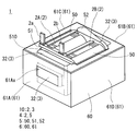
実施形態1では、図1~図4に基づいてリアクトル1の構成を説明する。図1に示すリアクトル1は、コイル2と磁性コア3の組合体10と、組合体10を収納するケース6と、を備える。このリアクトル1の特徴の一つとして、ケース6に設けたコア用切欠き部61Ax,61Bxからケース6の外部に磁性コア3の一部が露出していることを挙げることができる。以下、リアクトル1に備わる各構成を詳細に説明し、次いで、そのリアクトル1の製造方法を説明する。
実施形態1では、図1~図4に基づいてリアクトル1の構成を説明する。図1に示すリアクトル1は、コイル2と磁性コア3の組合体10と、組合体10を収納するケース6と、を備える。このリアクトル1の特徴の一つとして、ケース6に設けたコア用切欠き部61Ax,61Bxからケース6の外部に磁性コア3の一部が露出していることを挙げることができる。以下、リアクトル1に備わる各構成を詳細に説明し、次いで、そのリアクトル1の製造方法を説明する。
≪コイル≫
本実施形態のコイル2は、図4に示すように、一対の巻回部2A,2Bと、両巻回部2A,2Bを連結する連結部2R(図3)と、を備える。本例のコイル2に備わる巻回部2A,2Bは、巻線を螺旋状に巻回した部分で、互いに同一の巻数、同一の巻回方向で中空筒状に形成され、各軸方向が平行になるように並列されている。各巻回部2A,2Bで巻数や巻線の断面積が異なっても良い。また、本例では、一本の巻線でコイル2を製造しているが、別々の巻線により作製した巻回部2A,2Bを連結することでコイル2を製造しても構わない。
本実施形態のコイル2は、図4に示すように、一対の巻回部2A,2Bと、両巻回部2A,2Bを連結する連結部2R(図3)と、を備える。本例のコイル2に備わる巻回部2A,2Bは、巻線を螺旋状に巻回した部分で、互いに同一の巻数、同一の巻回方向で中空筒状に形成され、各軸方向が平行になるように並列されている。各巻回部2A,2Bで巻数や巻線の断面積が異なっても良い。また、本例では、一本の巻線でコイル2を製造しているが、別々の巻線により作製した巻回部2A,2Bを連結することでコイル2を製造しても構わない。
本実施形態の各巻回部2A,2Bは角筒状に形成されている。角筒状の巻回部2A,2Bとは、その端面形状が四角形状(正方形状を含む)の角を丸めた形状の巻回部のことである。もちろん、巻回部2A,2Bは円筒状に形成しても構わない。円筒状の巻回部とは、その端面形状が閉曲面形状(楕円形状や真円形状、レーストラック形状など)の巻回部のことである。
巻回部2A,2Bを含むコイル2は、銅やアルミニウム、マグネシウム、あるいはその合金といった導電性材料からなる平角線や丸線などの導体の外周に、絶縁性材料からなる絶縁被覆を備える被覆線によって構成することができる。本実施形態では、導体が銅製の平角線(巻線)からなり、絶縁被覆がエナメル(代表的にはポリイミド系樹脂)からなる被覆平角線をエッジワイズ巻きにすることで、各巻回部2A,2Bを形成している。
コイル2の両端部2a,2bは、巻回部2A,2Bから引き延ばされて、図示しない端子部材に接続される。両端部2a,2bではエナメルなどの絶縁被覆は剥がされている。この端子部材を介して、コイル2に電力供給を行なう電源などの外部装置が接続される。
[一体化樹脂]
本例のコイル2は、巻回部2A,2Bの各ターンがばらけないように一体化する一体化樹脂5を備えるコイル成形体4の形態で利用される。一体化樹脂5には、巻回部2A,2Bの伸張を抑制する機能や、コイル2と磁性コア3(図1)との間の絶縁を確保する機能がある。一体化樹脂5としては、例えば、ポリフェニレンスルフィド(PPS)樹脂、ポリテトラフルオロエチレン(PTFE)樹脂、液晶ポリマー(LCP)、ナイロン6やナイロン66といったポリアミド(PA)樹脂、ポリブチレンテレフタレート(PBT)樹脂、アクリロニトリル・ブタジエン・スチレン(ABS)樹脂などの熱可塑性樹脂で構成することができる。その他、不飽和ポリエステル樹脂、エポキシ樹脂、ウレタン樹脂、シリコーン樹脂などの熱硬化性樹脂などで一体化樹脂を形成することができる。上記樹脂にセラミックスフィラーを含有させて、一体化樹脂5の放熱性を向上させても良い。セラミックスフィラーとしては、例えば、アルミナやシリカ、窒化ホウ素、窒化アルミニウムなどの非磁性粉末を利用することができる。
本例のコイル2は、巻回部2A,2Bの各ターンがばらけないように一体化する一体化樹脂5を備えるコイル成形体4の形態で利用される。一体化樹脂5には、巻回部2A,2Bの伸張を抑制する機能や、コイル2と磁性コア3(図1)との間の絶縁を確保する機能がある。一体化樹脂5としては、例えば、ポリフェニレンスルフィド(PPS)樹脂、ポリテトラフルオロエチレン(PTFE)樹脂、液晶ポリマー(LCP)、ナイロン6やナイロン66といったポリアミド(PA)樹脂、ポリブチレンテレフタレート(PBT)樹脂、アクリロニトリル・ブタジエン・スチレン(ABS)樹脂などの熱可塑性樹脂で構成することができる。その他、不飽和ポリエステル樹脂、エポキシ樹脂、ウレタン樹脂、シリコーン樹脂などの熱硬化性樹脂などで一体化樹脂を形成することができる。上記樹脂にセラミックスフィラーを含有させて、一体化樹脂5の放熱性を向上させても良い。セラミックスフィラーとしては、例えば、アルミナやシリカ、窒化ホウ素、窒化アルミニウムなどの非磁性粉末を利用することができる。
本例の一体化樹脂5は、巻回部2A,2Bの各ターンを一体化するターン被覆部50と、巻回部2A,2Bの端面と外側コア部32との間に介在される端面被覆部51とを備える。さらに、一体化樹脂5は、巻回部2A,2Bの連結部2R(図3)を覆う連結部被覆部52を備える。
ターン被覆部50は、巻回部2A,2Bの内周面を覆う内周被覆部50Aと、巻回部2A,2Bの外周面の少なくとも一部を覆う外周被覆部50Bと、で構成されている(図4)。内周被覆部50Aは、巻回部2A,2Bの内周面全体を覆い、巻回部2A,2Bの伸張を抑制すると共に、巻回部2A,2Bと、その内部に配置される内側コア部31(図3)と、の間の絶縁を確保する。一方、外周被覆部50Bは、巻回部2A,2Bの外周面のうち、巻線が曲げられることで形成される四つの角部を覆い、巻回部2A,2Bの伸張を抑制する。ここで、巻回部2A,2Bのうち、巻線が曲げられていない平坦部には、外周被覆部50Bが形成されておらず、一体化樹脂5の外部に露出しているため、巻回部2A,2Bの外側面からの放熱が外周被覆部50Bによって阻害されることはない。
端面被覆部51は、巻回部2Aのターン被覆部50と巻回部2Bのターン被覆部50を連結するように設けられる。端面被覆部51には、巻回部2A,2Bの内部に連通する一対の貫通孔51h,51hが設けられている。この貫通孔51hを介して、巻回部2A,2Bの内部に内側コア部31(図3)を配置する。
端面被覆部51は、巻回部2A,2Bの軸方向にコイル2から離れる側に向って枠状に突出する枠部510を有する。その枠部510の外側面(巻回部2A,2Bの並列方向の面)は、ケース6のコイル対向壁61C,61Dの段差に当接する(図1,2参照)。枠部510は、ケース6におけるコイル2の位置決め、およびリアクトル1の作製時の複合材料の漏れを抑制する機能を持っている。
一体化樹脂5の別の形態として、例えば巻線の外周(エナメルなどの絶縁被覆のさらに外周)に熱融着性樹脂の被覆層を形成し、その被覆層同士を熱融着させた融着樹脂の形態を挙げることができる。この形態の場合、一体化樹脂5を非常に薄くできる、例えば1mm以下、さらには100μm以下とできるため、コイル2の放熱性を向上させることができる。また、巻回部2A,2Bをそれぞれ個別に一体化できるため、巻回部2A,2Bの間からコイル2の熱を逃がし易くできる。その他、巻回部2A,2Bの間に放熱部材を配置したり、コイル2の温度などを測定する各種センサを配置したりすることができる。
融着樹脂で構成される一体化樹脂5は非常に薄いため、巻回部2A,2Bの各ターンが一体化樹脂で5一体化されていても、巻回部2A,2Bのターンの形状や、ターンの境界が外観上から分かる状態になっている。この融着樹脂として、例えば、エポキシ樹脂、シリコーン樹脂、不飽和ポリエステルなどの熱硬化性樹脂を利用することもできる。
[磁性コア]
磁性コア3は、圧粉成形体や複合材料などで構成される磁性体である。この磁性コア3は、便宜上図3に示すように、巻回部2A,2Bの内部に配置される内側コア部31と、巻回部2A,2Bの外側に配置される外側コア部32と、に分けることができる。内側コア部31と外側コア部32はそれぞれ別々の材料で構成されていても良いし、同じ材料で構成されていても良い。前者の例として、内側コア部31を圧粉成形体、外側コア部32を複合材料で構成すること、後者の例として、内側コア部31と外側コア部32を複合材料で一体に構成することが挙げられる。本例では、コア部31,32を複合材料で一体に構成している。
磁性コア3は、圧粉成形体や複合材料などで構成される磁性体である。この磁性コア3は、便宜上図3に示すように、巻回部2A,2Bの内部に配置される内側コア部31と、巻回部2A,2Bの外側に配置される外側コア部32と、に分けることができる。内側コア部31と外側コア部32はそれぞれ別々の材料で構成されていても良いし、同じ材料で構成されていても良い。前者の例として、内側コア部31を圧粉成形体、外側コア部32を複合材料で構成すること、後者の例として、内側コア部31と外側コア部32を複合材料で一体に構成することが挙げられる。本例では、コア部31,32を複合材料で一体に構成している。
複合材料は、軟磁性粉末と樹脂とを含む磁性体である。軟磁性粉末は、鉄などの鉄族金属やその合金(Fe-Si合金、Fe-Si-Al合金、Fe-Ni合金など)などで構成される磁性粒子の集合体である。磁性粒子の表面にはリン酸塩などの絶縁被膜が形成されていても良い。樹脂としては、例えば、エポキシ樹脂、フェノール樹脂、シリコーン樹脂、ウレタン樹脂などの熱硬化性樹脂や、PPS樹脂、ナイロン6、ナイロン66といったPA樹脂、ポリイミド樹脂、フッ素樹脂などの熱可塑性樹脂などを利用できる。複合材料にはフィラーなどが含有されていても良い。フィラーとしては、例えば炭酸カルシウム、タルク、シリカ、クレー、アラミド繊維、カーボンファイバーやグラスファイバーなどの各種ファイバー、マイカ、ガラスフレークなどが利用できる。一方、圧粉成形体は、軟磁性粉末を含む原料粉末を加圧成形してなる磁性体である。
本例とは異なり、外側コア部32を複合材料で構成し、内側コア部31を圧粉成形体で構成しても良い。単独の圧粉成形体で内側コア部31を構成しても良いし、圧粉成形体のコア片とギャップ板とを交互に繋げて内側コア部31を構成しても良い。ギャップ板は、アルミナなどの非磁性材料からなる板材である。
ここで、本例の外側コア部32は、後述するリアクトルの製造方法に示すように、ケース6にコイル成形体4を収納した後、ケース6の内部に複合材料を射出成形または充填することで形成される。そのため、磁性コア3の外側コア部32は、ケース6の内周面に接合している。
外側コア部32の一部、本例では巻回部2A,2Bの軸方向における端面の一部が、後述するケース6の側壁部61に設けられるコア用切欠き部61Ax,61Bx(図1,2)からケース6の外部に露出している。ケース6から露出した外側コア部32の外周面は、ケース6の側壁部61の外周面と面一となっている。外側コア部32の露出部分には、放熱フィンなどの放熱部材を設けることができる。放熱フィンと外側コア部32との間に放熱グリスや放熱シートを介在させても良い。
≪ケース≫
ケース6は、図1,2に示すように、底板部60と側壁部61とで構成されている。底板部60と側壁部61とは一体に形成しても良いし、別々に用意した底板部60と側壁部61とを連結しても良い。ケース6の材料としては、例えばアルミニウムやその合金、マグネシウムやその合金などの非磁性金属、あるいは樹脂などを利用することができる。底板部60と側壁部61とを別体とするのであれば、両者60,61の材料を異ならせることもできる。例えば、底板部60を非磁性金属、側壁部61を樹脂とする、あるいはその逆とすることが挙げられる。
ケース6は、図1,2に示すように、底板部60と側壁部61とで構成されている。底板部60と側壁部61とは一体に形成しても良いし、別々に用意した底板部60と側壁部61とを連結しても良い。ケース6の材料としては、例えばアルミニウムやその合金、マグネシウムやその合金などの非磁性金属、あるいは樹脂などを利用することができる。底板部60と側壁部61とを別体とするのであれば、両者60,61の材料を異ならせることもできる。例えば、底板部60を非磁性金属、側壁部61を樹脂とする、あるいはその逆とすることが挙げられる。
本例の側壁部61は、外側コア部32の外周面に対向する一対のコア対向壁61A,61Bと、巻回部2A,2Bの外周面に対向する一対のコイル対向壁61C,61Dと、で構成されている。コア対向壁61A,61Bは、互いに平行で、巻回部2A,2Bの軸方向に離隔している。コイル対向壁61C,61Dは、互いに平行で、巻回部2A,2Bの並列方向に離隔している。
本例では、コア対向壁61A,61Bのそれぞれに、外側コア部32の一部をケース6の外方に露出させるコア用切欠き部61Ax,61Bxが設けられている。そのコア用切欠き部61Ax,61Bxの内部に外側コア部32の一部が入り込んでいる(図1,2の二点鎖線よりも外方側の部分を参照)。コア用切欠き部61Ax,61Bxの形状・大きさは特に限定されないが、図1に示すように本例のコア用切欠き部61Ax,61Bxは矩形状に形成されている。また、本例のコア用切欠き部61Ax(61Bx)の数は一つであるが、複数であっても良い。本例のコア用切欠き部61Ax,61Bxの矩形の上端はコア対向壁61A,61Bの上端に至り、下端は底板部60よりも若干上方に位置しており、左右端は外側コア部32の左右端面よりも内方に位置している。上記下端は底板部60に至っていても構わないが、本例のように底板部60よりも若干上方に位置することでケース6の剛性を高め易い。このような大きさと形状のコア用切欠き部61Ax,61Bxとすることで、ケース6からの外側コア部32の露出面積を大きくできる。また、コア用切欠き部61Ax,61Bxの左右長が外側コア部32の左右長よりも短いことで、巻回部2A,2Bの軸方向に、ケース6から組合体10が脱落することを抑制できる。
本例のケース6はさらに、図3のIII-III断面図に示すように、底板部60の位置に底孔部60xを備える。外側コア部32は底孔部60xにも入り込んでおり、その底孔部60xに入り込んだ部分は底板部60の底面と面一となっている。そのため、外側コア部32の熱をケース6の底面側からも放出し易くなっている。
≪リアクトルの効果≫
本例のリアクトル1では、リアクトル1を設置対象に固定するための応力がケース6内の組合体10に作用し難くできる。例えば、巻回部2A,2Bの軸方向の両側からリアクトル1を締め付ける取付金具を取り付けて、その取付金具を介してリアクトル1を設置対象に固定する場合、取付金具の締め付け力をケース6に受けさせることができる。また、ケース6の一部にネジ孔を有する固定部を形成し、固定部を設置対象にネジ止めする場合、ネジの締め付け力をケース6に受けさせることができる。いずれにせよ、ケース6内の組合体10に直接的に応力が作用することがない。
本例のリアクトル1では、リアクトル1を設置対象に固定するための応力がケース6内の組合体10に作用し難くできる。例えば、巻回部2A,2Bの軸方向の両側からリアクトル1を締め付ける取付金具を取り付けて、その取付金具を介してリアクトル1を設置対象に固定する場合、取付金具の締め付け力をケース6に受けさせることができる。また、ケース6の一部にネジ孔を有する固定部を形成し、固定部を設置対象にネジ止めする場合、ネジの締め付け力をケース6に受けさせることができる。いずれにせよ、ケース6内の組合体10に直接的に応力が作用することがない。
また、外側コア部32の外側面をケース6の側壁部61から露出させることで、外側コア部32からケース6の外部に熱が放出され易くなり、リアクトル1の放熱性をより向上させることができる。
≪用途≫
本例のリアクトル1は、ハイブリッド自動車や電気自動車、燃料電池自動車といった電動車両に搭載される双方向DC-DCコンバータなどの電力変換装置の構成部材に利用することができる。
本例のリアクトル1は、ハイブリッド自動車や電気自動車、燃料電池自動車といった電動車両に搭載される双方向DC-DCコンバータなどの電力変換装置の構成部材に利用することができる。
≪リアクトルの製造方法≫
次に、実施形態1に係るリアクトル1を製造するためのリアクトルの製造方法の一例を説明する。
次に、実施形態1に係るリアクトル1を製造するためのリアクトルの製造方法の一例を説明する。
まず、図4に示すコイル成形体4を用意する。そのコイル成形体4をケース6内に配置し、さらにそのケース6を金型内に配置する。金型は、ケース6内に複合材料で磁性コア3を形成する際、複合材料がケース6外に漏れない構成を備えるものであれば特に限定されない。例えば、金型は、ケース6の上端開口部を含めたケース6の外周全体を覆う物であっても良いし、コア用切欠き部61Ax,61Bxや底孔部60xのみを覆う物であっても良い。
次に、ケース6内の空間に複合材料を射出成形または充填し、巻回部2A,2Bの内部に内側コア部31を形成すると共に、ケース6の内周面に接合する外側コア部32を形成する。ケース6内の複合材料が固化または硬化したら、金型を取り外すことでリアクトル1を完成させることができる。
なお、コア片とギャップ板とを組み合わせて内側コア部31を構成する場合、コイル成形体4の貫通孔51hの内部に内側コア部31を挿入し、そのコイル成形体4と内側コア部31の組物をケース6に収納する。そして、コイル成形体4を収納したケース6を金型に配置し、ケース6内に未硬化の複合材料を射出成形または充填すると良い。その場合、内側コア部31の両端部にギャップ板を配置することで、射出成形時に複合材料が内側コア部31に接触し、内側コア部31が損傷することを抑制できる。
<実施形態2>
実施形態2では、ケース6のコア対向壁61A,61Bに、貫通孔状のコア用切欠き部61Axを設けた構成を図5に基づいて説明する。ここで、コア対向壁61Bに設けたコア用切欠き部は、図面上、見えない位置にあるが、コア用切欠き部61Axと同じ構成を備える。
実施形態2では、ケース6のコア対向壁61A,61Bに、貫通孔状のコア用切欠き部61Axを設けた構成を図5に基づいて説明する。ここで、コア対向壁61Bに設けたコア用切欠き部は、図面上、見えない位置にあるが、コア用切欠き部61Axと同じ構成を備える。
図5に示すように、本例のコア用切欠き部61Axは、側壁部61の内外に連通する貫通孔となっている。その貫通孔状のコア用切欠き部61Axには、外側コア部32の一部が嵌まり込んでおり、そのコア用切欠き部61Axに嵌まり込んだ部分がコア対向壁61Aの外周面と面一となっている。この構成によっても、外側コア部32の一部がケース6の側壁部61から露出しており、外側コア部32の熱を側方に放出し易くできる。
コア用切欠き部61Axを貫通孔状とすることで、外側コア部32のうち、コア用切欠き部61Axの内部に嵌まり込んだ部分の上面が、コア用切欠き部61Axの内周面に係合する。そのため、ケース6を横にしても逆さにしても、ケース6から組合体10が脱落することが無くなる。つまり、設置対象に対するリアクトル1の取付け方向の自由度が高くなる。また、この構成によれば、外側コア部32がコア用切欠き部61Axから露出するが、コア用切欠き部61Axに嵌まり込んでいない構成に比べて、ケース6との接触面積が大きくなり、ケース6を介して外側コア部32の熱を放熱し易くなる。
<実施形態3>
実施形態3では、外側コア部32に加えて、一方の巻回部2A,2Bの外側面がケース6から露出したリアクトル1を図6に基づいて説明する。実施形態1と同様の機能を有する構成には、実施形態1と同一の符号を付して、その説明を省略する。
実施形態3では、外側コア部32に加えて、一方の巻回部2A,2Bの外側面がケース6から露出したリアクトル1を図6に基づいて説明する。実施形態1と同様の機能を有する構成には、実施形態1と同一の符号を付して、その説明を省略する。
図6は、実施形態3のリアクトル1の概略上面図である。図6に示すように、本例のケース6には、コア用切欠き部61Ax,61Bxに加えて、側壁部61のコイル対向壁61Dにコイル用切欠き部61Dyが形成されている。コイル用切欠き部61Dyからは、巻回部2Bのうち、巻回部2A,2Bの並列方向の外側面がケース6の外方に露出している。
コイル用切欠き部61Dyの形状・大きさは特に限定されないが、本例では矩形状に形成されている。また、本例のコイル用切欠き部61Dyは一つであるが、複数であっても良い。本例のコイル用切欠き部61Dyの矩形の上端(紙面手前方向の端部)はコイル対向壁61Dの上端に至り、下端(紙面奥行き方向の端部)は巻回部2A,2Bの下方側の曲げ角部よりも高くなっており、左右端(紙面上下方向の端部)は巻回部2A,2Bの軸方向端面とほぼ面一となっている。このような大きさと形状のコイル用切欠き部61Dyとすることで、ケース6からの巻回部2Bの露出面積を大きくできる。また、コイル用切欠き部61Dyは、巻回部2Bを側面視した面積とほぼ同じであるが、一体化樹脂5を含むコイル成形体4を側面視した面積よりは小さいため、巻回部2A,2Bの並列方向に、ケース6から組合体10が脱落することを抑制できる。
実施形態3のリアクトル1では、コイル用切欠き部61Dyから露出する巻回部2Bの外周面に補強部材7を配置している。本例の補強部材7は、巻回部2Bの軸方向におけるケース6の長さと同じ長さを有しており、巻回部2Bの軸方向におけるコイル対向壁61Dの強度を保持する役割を持っている。そのため、例えば、巻回部2Bの軸方向にコイル対向壁61Dを締め付けて、補強部材7を設置対象への取付け面とする側方固定を行なう場合、補強部材7に締め付け力を受圧させることができ、ケース6の変形やそれに伴う組合体10への応力負荷を低減できる。
また、本例の補強部材7は、ケース6と同等か、それよりも熱伝導性に優れる材料で構成されており、コイル2の放熱性を向上させる放熱部材としても機能する。巻回部2Bと補強部材(放熱部材)7との間には、放熱グリスや発泡性の放熱シートなどの熱伝導材料を設けて、巻回部2Bから補強部材7への熱伝導を促進しても良い。
なお、コイル対向壁61Dを締め付けずに、コイル対向壁61Dを設置対象への取付け面とする側方固定を行なう場合、補強部材7は無くても良い。その場合、コイル対向壁61Dと設置対象との間に、放熱部材として放熱グリスや放熱シートなどを介在させると良い。
<実施形態4>
実施形態4では、外側コア部32に加えて、両巻回部2A,2Bの外側面がケース6から露出したリアクトル1を図7に基づいて説明する。実施形態3と同様の機能を有する構成には、実施形態3と同一の符号を付して、その説明を省略する。
実施形態4では、外側コア部32に加えて、両巻回部2A,2Bの外側面がケース6から露出したリアクトル1を図7に基づいて説明する。実施形態3と同様の機能を有する構成には、実施形態3と同一の符号を付して、その説明を省略する。
図7は、実施形態4のリアクトル1の概略上面図である。図7に示すように、本例のケース6には、コイル用切欠き部61Dyに加えて、コイル対向壁61Cにもコイル用切欠き部61Cyが形成されている。この構成によれば、組合体10の四方がケース6外に露出するので、リアクトル1の放熱性を高め易い。
本例の側壁部61は、四本の離隔した柱のようになっている。そのため、リアクトル1を取付金具などで締め付けてリアクトル1を設置対象に固定する場合、側壁部61に締め付け方向の耐力を持たせることが好ましい。図7の例では、巻回部2A,2Bの軸方向に締め付け力が作用することを想定し、コイル対向壁61C,61Dの外側にそれぞれ、コイル対向壁61C,61Dと同じ長さの補強部材7,7を配置している。この補強部材7,7も、実施形態3と同様に、ケース6と同等か、それよりも熱伝導性に優れる材料で構成することで、巻回部2A,2Bからの放熱を促すことができる。
1 リアクトル
10 組合体
2 コイル
2A,2B 巻回部 2R 連結部 2a,2b 端部
3 磁性コア
31 内側コア部 32 外側コア部
4 コイル成形体
5 一体化樹脂
50 ターン被覆部 50A 内周被覆部 50B 外周被覆部
51 端面被覆部 52 連結部被覆部
51h 貫通孔 510 枠部
6 ケース
60 底板部 60x 底孔部
61 側壁部 61A,61B コア対向壁
61C,61D コイル対向壁
61Ax,61Bx コア用切欠き部
61Cy,61Dy コイル用切欠き部
7 補強部材(放熱部材)
10 組合体
2 コイル
2A,2B 巻回部 2R 連結部 2a,2b 端部
3 磁性コア
31 内側コア部 32 外側コア部
4 コイル成形体
5 一体化樹脂
50 ターン被覆部 50A 内周被覆部 50B 外周被覆部
51 端面被覆部 52 連結部被覆部
51h 貫通孔 510 枠部
6 ケース
60 底板部 60x 底孔部
61 側壁部 61A,61B コア対向壁
61C,61D コイル対向壁
61Ax,61Bx コア用切欠き部
61Cy,61Dy コイル用切欠き部
7 補強部材(放熱部材)
Claims (9)
- 並列された一対の巻回部を有するコイルと、
前記巻回部の内部に配置される内側コア部、および前記巻回部から露出する外側コア部を有する磁性コアと、
前記コイルと前記磁性コアの組合体を収納するケースと、
を備えるリアクトルであって、
前記ケースは、
前記組合体を載置する底板部と、
前記底板部から立設される側壁部と、を備え、
前記側壁部は、前記外側コア部の少なくとも一部を前記ケースの外方に露出させるコア用切欠き部を備えるリアクトル。 - 前記コア用切欠き部は、前記側壁部の内外に連通する貫通孔であり、
前記外側コア部の一部が、前記貫通孔の内部に嵌まり込んだ状態で保持されている請求項1に記載のリアクトル。 - 前記底板部は、前記外側コア部の少なくとも一部を前記ケースの下方に露出させる底孔部を備える請求項1または請求項2に記載のリアクトル。
- 前記外側コア部は、軟磁性粉末と樹脂とを含む複合材料で構成され、
前記外側コア部の少なくとも一部が、前記ケースの内周面に接合している請求項1から請求項3のいずれか1項に記載のリアクトル。 - 前記側壁部は、前記巻回部が並列される方向を並列方向としたとき、一方の前記巻回部における前記並列方向の外側面、または他方の前記巻回部における前記並列方向の外側面を前記ケースの外方に露出させるコイル用切欠き部を備える請求項1から請求項4のいずれか1項に記載のリアクトル。
- 前記側壁部は、前記巻回部が並列される方向を並列方向としたとき、一方の前記巻回部における前記並列方向の外側面、および他方の前記巻回部における前記並列方向の外側面をそれぞれ前記ケースの外方に露出させるコイル用切欠き部を備える請求項1から請求項4のいずれか1項に記載のリアクトル。
- 前記巻回部のうち、前記コイル用切欠き部から前記ケースの外方に露出する部分に、放熱部材を備える請求項5または請求項6に記載のリアクトル。
- 前記外側コア部のうち、前記コア用切欠き部から前記ケースの外方に露出する部分に、放熱部材を備える請求項1から請求項7のいずれか1項に記載のリアクトル。
- 前記コイルは、絶縁性樹脂で構成される一体化樹脂を備え、
前記一体化樹脂は、
前記巻回部の各ターンを一体化するターン被覆部と、
前記巻回部の端面と前記外側コア部との間に介在される端面被覆部と、を備える請求項1から請求項8のいずれか1項に記載のリアクトル。
Priority Applications (2)
| Application Number | Priority Date | Filing Date | Title |
|---|---|---|---|
| US16/489,097 US11495386B2 (en) | 2017-03-03 | 2018-02-23 | Reactor |
| CN201880011878.1A CN110326071B (zh) | 2017-03-03 | 2018-02-23 | 电抗器 |
Applications Claiming Priority (2)
| Application Number | Priority Date | Filing Date | Title |
|---|---|---|---|
| JP2017-041148 | 2017-03-03 | ||
| JP2017041148A JP6593780B2 (ja) | 2017-03-03 | 2017-03-03 | リアクトル |
Publications (1)
| Publication Number | Publication Date |
|---|---|
| WO2018159503A1 true WO2018159503A1 (ja) | 2018-09-07 |
Family
ID=63370724
Family Applications (1)
| Application Number | Title | Priority Date | Filing Date |
|---|---|---|---|
| PCT/JP2018/006785 Ceased WO2018159503A1 (ja) | 2017-03-03 | 2018-02-23 | リアクトル |
Country Status (4)
| Country | Link |
|---|---|
| US (1) | US11495386B2 (ja) |
| JP (1) | JP6593780B2 (ja) |
| CN (1) | CN110326071B (ja) |
| WO (1) | WO2018159503A1 (ja) |
Cited By (1)
| Publication number | Priority date | Publication date | Assignee | Title |
|---|---|---|---|---|
| CN114158285A (zh) * | 2019-07-29 | 2022-03-08 | 株式会社自动网络技术研究所 | 线束的散热构造 |
Families Citing this family (5)
| Publication number | Priority date | Publication date | Assignee | Title |
|---|---|---|---|---|
| JP6656594B2 (ja) * | 2017-05-22 | 2020-03-04 | 株式会社オートネットワーク技術研究所 | リアクトル |
| JP6948300B2 (ja) * | 2018-09-25 | 2021-10-13 | 株式会社タムラ製作所 | リアクトルの製造方法 |
| JP7089672B2 (ja) * | 2018-10-25 | 2022-06-23 | 株式会社オートネットワーク技術研究所 | リアクトル |
| JP7613880B2 (ja) | 2020-10-23 | 2025-01-15 | 株式会社トーキン | リアクトル |
| GB2618373B (en) * | 2022-05-05 | 2024-09-11 | Murata Manufacturing Co | Hybrid construction transformer |
Citations (15)
| Publication number | Priority date | Publication date | Assignee | Title |
|---|---|---|---|---|
| JP2006310539A (ja) * | 2005-04-28 | 2006-11-09 | Sumida Corporation | チョークコイル |
| JP2009231495A (ja) * | 2008-03-21 | 2009-10-08 | Toyota Motor Corp | リアクトル |
| JP2010118465A (ja) * | 2008-11-12 | 2010-05-27 | Tamura Seisakusho Co Ltd | インダクタ |
| JP2010226138A (ja) * | 2008-08-22 | 2010-10-07 | Sumitomo Electric Ind Ltd | リアクトル用部品およびリアクトル |
| JP2011071466A (ja) * | 2009-03-25 | 2011-04-07 | Sumitomo Electric Ind Ltd | リアクトル |
| WO2011101976A1 (ja) * | 2010-02-19 | 2011-08-25 | トヨタ自動車株式会社 | 電磁機器及びその製造方法 |
| JP2013115140A (ja) * | 2011-11-25 | 2013-06-10 | Toyota Motor Corp | リアクトルおよびその製造方法 |
| JP2013149869A (ja) * | 2012-01-20 | 2013-08-01 | Tamura Seisakusho Co Ltd | リアクトル及びその製造方法 |
| JP2013197567A (ja) * | 2012-03-23 | 2013-09-30 | Tamura Seisakusho Co Ltd | リアクトル及びその製造方法 |
| JP2015012147A (ja) * | 2013-06-28 | 2015-01-19 | 株式会社オートネットワーク技術研究所 | リアクトル |
| JP2015095563A (ja) * | 2013-11-12 | 2015-05-18 | 株式会社タムラ製作所 | リアクトル |
| JP2015103627A (ja) * | 2013-11-22 | 2015-06-04 | 株式会社タムラ製作所 | リアクトル |
| JP2015153929A (ja) * | 2014-02-17 | 2015-08-24 | 株式会社デンソー | リアクトル |
| JP2015170674A (ja) * | 2014-03-06 | 2015-09-28 | 株式会社デンソー | リアクトル |
| JP2018041927A (ja) * | 2016-09-09 | 2018-03-15 | 株式会社タムラ製作所 | リアクトルとその製造方法 |
Family Cites Families (8)
| Publication number | Priority date | Publication date | Assignee | Title |
|---|---|---|---|---|
| CN1894755B (zh) * | 2003-12-10 | 2011-11-16 | 株式会社田村制作所 | 变压器 |
| JP4650755B1 (ja) | 2009-08-31 | 2011-03-16 | 住友電気工業株式会社 | リアクトル |
| JP5120679B1 (ja) | 2011-05-10 | 2013-01-16 | 住友電気工業株式会社 | リアクトル |
| JP5120678B2 (ja) | 2011-05-10 | 2013-01-16 | 住友電気工業株式会社 | リアクトル |
| JP5893505B2 (ja) * | 2012-05-15 | 2016-03-23 | 株式会社タムラ製作所 | リアクトル |
| JP5697707B2 (ja) * | 2013-03-28 | 2015-04-08 | トヨタ自動車株式会社 | リアクトル |
| US9343223B2 (en) | 2013-03-29 | 2016-05-17 | Tamura Corporation | Reactor |
| JP6288531B2 (ja) * | 2014-06-24 | 2018-03-07 | 株式会社オートネットワーク技術研究所 | コア部材、リアクトル、及びコア部材の製造方法 |
-
2017
- 2017-03-03 JP JP2017041148A patent/JP6593780B2/ja active Active
-
2018
- 2018-02-23 WO PCT/JP2018/006785 patent/WO2018159503A1/ja not_active Ceased
- 2018-02-23 US US16/489,097 patent/US11495386B2/en active Active
- 2018-02-23 CN CN201880011878.1A patent/CN110326071B/zh active Active
Patent Citations (15)
| Publication number | Priority date | Publication date | Assignee | Title |
|---|---|---|---|---|
| JP2006310539A (ja) * | 2005-04-28 | 2006-11-09 | Sumida Corporation | チョークコイル |
| JP2009231495A (ja) * | 2008-03-21 | 2009-10-08 | Toyota Motor Corp | リアクトル |
| JP2010226138A (ja) * | 2008-08-22 | 2010-10-07 | Sumitomo Electric Ind Ltd | リアクトル用部品およびリアクトル |
| JP2010118465A (ja) * | 2008-11-12 | 2010-05-27 | Tamura Seisakusho Co Ltd | インダクタ |
| JP2011071466A (ja) * | 2009-03-25 | 2011-04-07 | Sumitomo Electric Ind Ltd | リアクトル |
| WO2011101976A1 (ja) * | 2010-02-19 | 2011-08-25 | トヨタ自動車株式会社 | 電磁機器及びその製造方法 |
| JP2013115140A (ja) * | 2011-11-25 | 2013-06-10 | Toyota Motor Corp | リアクトルおよびその製造方法 |
| JP2013149869A (ja) * | 2012-01-20 | 2013-08-01 | Tamura Seisakusho Co Ltd | リアクトル及びその製造方法 |
| JP2013197567A (ja) * | 2012-03-23 | 2013-09-30 | Tamura Seisakusho Co Ltd | リアクトル及びその製造方法 |
| JP2015012147A (ja) * | 2013-06-28 | 2015-01-19 | 株式会社オートネットワーク技術研究所 | リアクトル |
| JP2015095563A (ja) * | 2013-11-12 | 2015-05-18 | 株式会社タムラ製作所 | リアクトル |
| JP2015103627A (ja) * | 2013-11-22 | 2015-06-04 | 株式会社タムラ製作所 | リアクトル |
| JP2015153929A (ja) * | 2014-02-17 | 2015-08-24 | 株式会社デンソー | リアクトル |
| JP2015170674A (ja) * | 2014-03-06 | 2015-09-28 | 株式会社デンソー | リアクトル |
| JP2018041927A (ja) * | 2016-09-09 | 2018-03-15 | 株式会社タムラ製作所 | リアクトルとその製造方法 |
Cited By (2)
| Publication number | Priority date | Publication date | Assignee | Title |
|---|---|---|---|---|
| CN114158285A (zh) * | 2019-07-29 | 2022-03-08 | 株式会社自动网络技术研究所 | 线束的散热构造 |
| CN114158285B (zh) * | 2019-07-29 | 2024-01-09 | 株式会社自动网络技术研究所 | 线束的散热构造 |
Also Published As
| Publication number | Publication date |
|---|---|
| US11495386B2 (en) | 2022-11-08 |
| CN110326071A (zh) | 2019-10-11 |
| US20200075215A1 (en) | 2020-03-05 |
| CN110326071B (zh) | 2021-04-27 |
| JP2018148007A (ja) | 2018-09-20 |
| JP6593780B2 (ja) | 2019-10-23 |
Similar Documents
| Publication | Publication Date | Title |
|---|---|---|
| JP6593780B2 (ja) | リアクトル | |
| JP5263720B2 (ja) | リアクトル用部品の製造方法及びリアクトル本体の製造方法 | |
| JP6384732B2 (ja) | リアクトル | |
| JP5343387B2 (ja) | リアクトル、及びコンバータ | |
| US20190131052A1 (en) | Reactor | |
| JP6376461B2 (ja) | リアクトル | |
| US12062477B2 (en) | Reactor | |
| US20190267184A1 (en) | Reactor and method for producing reactor | |
| US11017935B2 (en) | Reactor | |
| JP2016096271A (ja) | リアクトル | |
| JP6610903B2 (ja) | リアクトル | |
| WO2018020988A1 (ja) | リアクトル | |
| CN112582135B (zh) | 电抗器 | |
| JP6362030B2 (ja) | リアクトル | |
| US11342105B2 (en) | Coil, magnetic core, and reactor | |
| US20210398728A1 (en) | Reactor | |
| JP6468466B2 (ja) | リアクトル | |
| JP2011009660A (ja) | リアクトル | |
| JP6436352B2 (ja) | リアクトル | |
| JP2024147896A (ja) | リアクトル | |
| WO2020105469A1 (ja) | リアクトル | |
| WO2020111160A1 (ja) | リアクトル |
Legal Events
| Date | Code | Title | Description |
|---|---|---|---|
| 121 | Ep: the epo has been informed by wipo that ep was designated in this application |
Ref document number: 18761217 Country of ref document: EP Kind code of ref document: A1 |
|
| NENP | Non-entry into the national phase |
Ref country code: DE |
|
| 122 | Ep: pct application non-entry in european phase |
Ref document number: 18761217 Country of ref document: EP Kind code of ref document: A1 |