WO2018159298A1 - 内燃機関の可変動弁システム及び可変動弁機構のコントロール装置 - Google Patents
内燃機関の可変動弁システム及び可変動弁機構のコントロール装置 Download PDFInfo
- Publication number
- WO2018159298A1 WO2018159298A1 PCT/JP2018/005157 JP2018005157W WO2018159298A1 WO 2018159298 A1 WO2018159298 A1 WO 2018159298A1 JP 2018005157 W JP2018005157 W JP 2018005157W WO 2018159298 A1 WO2018159298 A1 WO 2018159298A1
- Authority
- WO
- WIPO (PCT)
- Prior art keywords
- valve
- exhaust
- timing
- intake
- variable valve
- Prior art date
- Legal status (The legal status is an assumption and is not a legal conclusion. Google has not performed a legal analysis and makes no representation as to the accuracy of the status listed.)
- Ceased
Links
Images




Classifications
-
- F—MECHANICAL ENGINEERING; LIGHTING; HEATING; WEAPONS; BLASTING
- F02—COMBUSTION ENGINES; HOT-GAS OR COMBUSTION-PRODUCT ENGINE PLANTS
- F02D—CONTROLLING COMBUSTION ENGINES
- F02D13/00—Controlling the engine output power by varying inlet or exhaust valve operating characteristics, e.g. timing
- F02D13/02—Controlling the engine output power by varying inlet or exhaust valve operating characteristics, e.g. timing during engine operation
-
- F—MECHANICAL ENGINEERING; LIGHTING; HEATING; WEAPONS; BLASTING
- F02—COMBUSTION ENGINES; HOT-GAS OR COMBUSTION-PRODUCT ENGINE PLANTS
- F02D—CONTROLLING COMBUSTION ENGINES
- F02D21/00—Controlling engines characterised by their being supplied with non-airborne oxygen or other non-fuel gas
- F02D21/06—Controlling engines characterised by their being supplied with non-airborne oxygen or other non-fuel gas peculiar to engines having other non-fuel gas added to combustion air
- F02D21/08—Controlling engines characterised by their being supplied with non-airborne oxygen or other non-fuel gas peculiar to engines having other non-fuel gas added to combustion air the other gas being the exhaust gas of engine
-
- F—MECHANICAL ENGINEERING; LIGHTING; HEATING; WEAPONS; BLASTING
- F02—COMBUSTION ENGINES; HOT-GAS OR COMBUSTION-PRODUCT ENGINE PLANTS
- F02D—CONTROLLING COMBUSTION ENGINES
- F02D41/00—Electrical control of supply of combustible mixture or its constituents
- F02D41/02—Circuit arrangements for generating control signals
- F02D41/04—Introducing corrections for particular operating conditions
- F02D41/06—Introducing corrections for particular operating conditions for engine starting or warming up
-
- F—MECHANICAL ENGINEERING; LIGHTING; HEATING; WEAPONS; BLASTING
- F02—COMBUSTION ENGINES; HOT-GAS OR COMBUSTION-PRODUCT ENGINE PLANTS
- F02M—SUPPLYING COMBUSTION ENGINES IN GENERAL WITH COMBUSTIBLE MIXTURES OR CONSTITUENTS THEREOF
- F02M26/00—Engine-pertinent apparatus for adding exhaust gases to combustion-air, main fuel or fuel-air mixture, e.g. by exhaust gas recirculation [EGR] systems
- F02M26/01—Internal exhaust gas recirculation, i.e. wherein the residual exhaust gases are trapped in the cylinder or pushed back from the intake or the exhaust manifold into the combustion chamber without the use of additional passages
-
- Y—GENERAL TAGGING OF NEW TECHNOLOGICAL DEVELOPMENTS; GENERAL TAGGING OF CROSS-SECTIONAL TECHNOLOGIES SPANNING OVER SEVERAL SECTIONS OF THE IPC; TECHNICAL SUBJECTS COVERED BY FORMER USPC CROSS-REFERENCE ART COLLECTIONS [XRACs] AND DIGESTS
- Y02—TECHNOLOGIES OR APPLICATIONS FOR MITIGATION OR ADAPTATION AGAINST CLIMATE CHANGE
- Y02T—CLIMATE CHANGE MITIGATION TECHNOLOGIES RELATED TO TRANSPORTATION
- Y02T10/00—Road transport of goods or passengers
- Y02T10/10—Internal combustion engine [ICE] based vehicles
- Y02T10/12—Improving ICE efficiencies
-
- Y—GENERAL TAGGING OF NEW TECHNOLOGICAL DEVELOPMENTS; GENERAL TAGGING OF CROSS-SECTIONAL TECHNOLOGIES SPANNING OVER SEVERAL SECTIONS OF THE IPC; TECHNICAL SUBJECTS COVERED BY FORMER USPC CROSS-REFERENCE ART COLLECTIONS [XRACs] AND DIGESTS
- Y02—TECHNOLOGIES OR APPLICATIONS FOR MITIGATION OR ADAPTATION AGAINST CLIMATE CHANGE
- Y02T—CLIMATE CHANGE MITIGATION TECHNOLOGIES RELATED TO TRANSPORTATION
- Y02T10/00—Road transport of goods or passengers
- Y02T10/10—Internal combustion engine [ICE] based vehicles
- Y02T10/40—Engine management systems
Definitions
- the present invention relates to a variable valve system for an internal combustion engine, and more particularly to a variable valve system for an internal combustion engine having a variable valve mechanism for controlling the opening and closing phases of an intake valve and an exhaust valve, and a control device for the variable valve mechanism. is there.
- variable valve mechanism for controlling the opening / closing phase of an intake valve or an exhaust valve of an internal combustion engine
- a variable phase variable valve mechanism for controlling the opening / closing phase of the intake valve
- PVO positive valve overlap
- high-temperature residual gas containing unburned HC is caused to flow back to the intake system during the period of “positive valve overlap” (PVO) at the beginning of startup, and unburned in the subsequent intake stroke thereafter.
- PVO positive valve overlap
- Non-Patent Document 1 high-temperature residual gas including unburned HC is caused to flow back to the intake system during the period of “positive valve overlap” (PVO) at the initial stage of starting, and the subsequent intake air thereafter.
- PVO positive valve overlap
- the unburned HC reintroduces the residual gas containing soot into the cylinder and re-combusts it, thereby reducing the emission of harmful exhaust components in the exhaust gas.
- the main object of the present invention is to provide a novel variable valve system for an internal combustion engine and a variable valve control apparatus capable of reducing harmful exhaust components in exhaust gas by suppressing deterioration of combustion at the time of cold start. There is.
- the intake valve opening timing (IVOc) is set to an advanced angle side with respect to the most retarded angle opening timing (IVOrtd) by the intake valve variable valve mechanism.
- the exhaust angle is set to the retarded angle side by a predetermined angle (ITc) from the exhaust top dead center (TDC), and the exhaust valve variable valve mechanism is used to close the exhaust valve (EVCc).
- the negative valve overlap (NVOc) is formed so that the intake valve opening timing (IVOc) and the exhaust valve closing timing (EVCc) do not overlap.
- a “negative valve overlap” is formed from the end of the exhaust stroke to the beginning of the intake stroke, thereby producing a high temperature combustion gas (high temperature EGR).
- Gas is contained in the cylinder, and the remaining cylinder gas and the engine body are heated by pressurizing with a piston, suppressing deterioration of combustion at the time of cold start, and exhaust harmful components in the exhaust gas. Can be reduced.
- FIG. 1 shows a configuration of a main part of a variable valve system of an internal combustion engine.
- An exhaust camshaft 10 is provided with two exhaust cams 11 per cylinder.
- the exhaust cam 11 opens and closes the exhaust valve 12.
- a sprocket mechanism 13 and an exhaust valve variable valve mechanism (hereinafter referred to as an exhaust VTC) 14 fixed to the sprocket mechanism 13 are attached to one end of the exhaust camshaft 10, and the exhaust camshaft 10 is connected to the sprocket mechanism.
- the relative rotational position of the exhaust cam 11 is controlled by making relative rotation (phase conversion) with respect to 13.
- the sprocket mechanism 13 includes a timing sprocket 15 and is rotated by a crankshaft by a timing belt (not shown).
- the exhaust VTC 14 includes a housing 16 and a vane that is hydraulically driven in a space formed by the front cover 17 and the rear cover 18 fixed to both ends of the housing 16.
- the timing sprocket 15 and the rear cover 18 are fixed to each other, and the vane is fixed to the exhaust camshaft 10. Therefore, by adjusting the rotational position of the vane by hydraulic pressure, the exhaust camshaft 10 adjusts the opening / closing phase of the exhaust valve correspondingly.
- the intake camshaft 20 is provided with two intake cams 21 per cylinder.
- the intake cam 21 opens and closes the intake valve 22.
- a sprocket mechanism 23 and an intake valve variable valve mechanism (hereinafter referred to as intake VTC) 24 fixed to the sprocket mechanism 23 are attached to one end of the intake camshaft 20, and the intake camshaft 20 is connected to the sprocket mechanism.
- the relative rotational position of the intake cam 21 is controlled by relative rotation (phase conversion) with respect to 23.
- the sprocket mechanism 23 includes a timing sprocket 25, and is rotated by a crankshaft by a timing belt (not shown).
- the intake VTC 24 has a housing 26 and a vane that is hydraulically driven in a space formed by a front cover 27 and a rear cover 28 fixed to both ends of the housing 26.
- the timing sprocket 25 and the rear cover 28 are fixed to each other, and the vane is fixed to the intake camshaft 20. Therefore, the intake camshaft 20 adjusts the opening / closing phase of the intake valve correspondingly by adjusting the rotational position of the vane by hydraulic pressure.
- the control device 30 receives various operating state information of the internal combustion engine, an exhaust VTC actual position signal, an intake VTC actual position signal, and the like, supplies an exhaust phase control signal to the exhaust electromagnetic switching valve 31, and supplies an intake phase control signal.
- the intake electromagnetic switching valve 32 By supplying the intake electromagnetic switching valve 32, the exhaust phase control hydraulic pressure of the exhaust VTC 14 and the intake phase control hydraulic pressure of the intake VTC 24 are controlled.
- the housing 35 (16) has a cylindrical housing body 35a whose front end opening is closed by a disc-shaped front cover 17 (see FIG. 1) and whose rear end opening is a disk.
- the rear cover 18 (see FIG. 1) is closed.
- shoes 35b that are four partition walls project from the inner side.
- the rear cover 18 is integrally provided at the center position of the timing sprocket 13, and the outer peripheral portion thereof is fastened to the housing body 35 a and the front cover 17 by four bolts 39.
- a large-diameter bearing hole that is supported on the outer periphery of the cylindrical portion of the vane rotor 36 is formed in the center of the rear cover 18 in the axial direction.
- the vane rotor 36 includes a cylindrical rotor 37 having a bolt insertion hole in the center, and four vanes 38 and 38a provided integrally at approximately 90 ° in the circumferential direction of the outer peripheral surface of the rotor 37.
- the rotor 37 has a small diameter cylindrical portion on the front end side rotatably supported by the central support hole of the front cover 17, while a small diameter cylindrical portion on the rear end side is rotatably supported by the bearing hole of the rear cover 18. .
- the vane rotor 36 is fixed to the front end portion of the exhaust camshaft 10 from the axial direction by a fixing bolt 40 inserted through the bolt insertion hole of the rotor 37 from the axial direction.
- Each vane 38, 38a is disposed between each shoe 35b, and a seal member that slidably contacts the inner peripheral surface of the housing main body 35a in an elongated holding groove formed in the axial direction of each outer surface and the seal.
- a leaf spring that presses the member in the direction of the inner peripheral surface of the housing body is fitted and held.
- retarding chambers 41 and advance chambers 42 are respectively formed between both sides of the vanes 38 and 38a and both sides of the shoes 35b.
- the vane 38a has an advance side stopper function and a retard side stopper function.
- the intake VTC 24 has the same configuration, but the advance chamber and the retard chamber have an opposite relationship, and the four coil springs that constantly urge the vane rotor 36 in the retard direction include the retard chamber. Are attached to each.
- the intermediate angle time (Emid) is between the most advanced angle time (Emax) and the most retarded angle time (Emin), and is slightly behind the most advanced angle time (Emax).
- the fastening pin 45 built in the vane 38a and the fastening hole on the rear cover 18 side coincide with each other, and the vanes 38a and 38 are positioned at the default position. It is like that.
- the intake VTC 24 has a structure similar to that of the exhaust VTC 14 shown in FIG. 2, but the conversion phase angle formed between the most advanced angle timing (Imax) and the most retarded angle magnetism (Imin) is larger than that of the exhaust VTC 14. Is set.
- the intermediate angle timing (Imid) is set between the most advanced timing (Imax) and the most retarded timing (Imin), and the fastening pin in the vane matches the fastening hole on the rear cover side.
- the default position is set to the retard side that is larger than the most advanced timing (Imax), and is set to be slightly advanced from the most retarded timing (Imin).
- the fastening pin in the vane and the fastening hole on the rear cover 28 coincide with each other like the exhaust VTC 14 so that the vane is positioned at the default position. It has become.
- FIG. 3 “(A) cold start state”, “(B) partial load state after warm-up”, and “(C) post-warm state”.
- Each valve timing characteristic of “full load state” is shown.
- “(A) the cold start state” is, for example, a state where the main body temperature of the internal combustion engine is 40 ° C. or less
- “(B) the partial load state after warming up” is, for example, the accelerator pedal being in the middle
- “(C) full load state after warm-up” is a state where, for example, the accelerator pedal is depressed to the maximum extent.
- each valve timing characteristic will be described.
- valve timings of the exhaust valve and the intake valve are the valve timings shown in “(A) Cold machine start state” in FIG.
- the exhaust top dead center is when the exhaust valve closing timing (EVC) is more retarded than the exhaust valve most advanced timing (EVCadv) and more advanced than the most retarded timing (EVCrtd).
- the exhaust valve closing timing (EVCc) on the advance side is set by a predetermined angle (ETc) from (TDC).
- EDC exhaust valve closing timing
- the intake valve opening timing (IVO) is an advance side of the most retarded angle opening timing (IVOrtd) of the intake valve, and is between the retarded side of the most advanced angle opening timing (IVOaddv) and the exhaust top dead center (
- the intake valve opening timing (IVOc) is set at a delay angle side by a predetermined angle (ITc) from TDC).
- the most advanced angle opening time (IVOadv) is the same as the most advanced angle time (Imax)
- the most retarded angle opening time (IVOrtd) is the same as the most retarded angle time (Imin).
- the predetermined angle (ITc) and the predetermined angle (ETc) are set to substantially the same angle.
- substantially the same angle is a concept including mechanical errors after assembly of the exhaust VTC 14 and the intake VTC 24, design tolerances, and the like, and does not necessarily mean the same angle.
- high temperature combustion gas high temperature EGR gas
- NVOc negative valve overlap
- the intake valve opening timing (IVOc) is retarded in the present embodiment.
- the period (intake operating angle) can be set narrow, whereby the valve friction resistance of the intake valve can be reduced and the use of the driving force of the internal combustion engine can be suppressed.
- the exhaust valve closing timing (EVCc) is advanced in this embodiment.
- the valve opening period (exhaust operating angle) can be set narrow, whereby the valve frictional resistance of the exhaust valve can be reduced, and use of the driving force of the internal combustion engine can be suppressed.
- the exhaust valve opening timing EVO
- the exhaust valve is opened before the combustion gas temperature decreases, and the exhaust gas having a high temperature is supplied to the exhaust gas purification catalyst. It is possible to increase the temperature of the exhaust gas purifying catalyst to reduce harmful components of exhaust gas at the time of cold start while suppressing an increase in valve frictional resistance.
- the EGR gas can also be introduced into the cylinder by the conventional “positive valve overlap” (PVO).
- the temperature of the EGR gas is in principle the “negative valve overlap” according to the present embodiment. It is lower than (NVO), and the valve opening period (intake / exhaust operating angle) of the intake valve and the exhaust valve is set to be large, so there is a problem that the valve friction resistance of the intake valve and the exhaust valve increases. .
- the intake valve opening timing (IVO) is further retarded than the intake valve opening timing (IVOc) in the cold start state, and the exhaust The timing is converted into the open timing (IVOp) on the retard side by a predetermined angle (ITp) from the dead point (TDC).
- the opening timing (IVOp) is the same as the most retarded opening timing (IVOrtd).
- the intake valve closing timing (IVC) is set to the intake valve closing timing (IVCp) retarded to near the middle position between the intake bottom dead center (BDC) and the compression top dead center (TDC).
- the vane may be phase-converted by the intake VTC 24 until the aforementioned most retarded opening timing (Imin) of the intake valve.
- the exhaust valve closing timing (EVC) is further advanced than the exhaust valve closing timing (EVCc) in the cold start state, and the exhaust The dead time (TDC) is converted into the closing timing (EVCp) on the advance side by a predetermined angle (ETp).
- the closing time (EVCp) is the same as the most advanced angle closing time (EVCadv).
- the exhaust valve opening timing (EVO) is advanced to a section between the exhaust bottom dead center (BDC) and the compression top dead center (TDC) to open the exhaust valve opening timing (EVOp).
- BDC exhaust bottom dead center
- TDC compression top dead center
- the vanes 38a and 38 may be phase-converted by the exhaust VTC 14 up to the most advanced timing (Emax) of the exhaust valve.
- the frictional resistance of the internal combustion engine mechanism system may be lower than that in the cold state, and the intake air amount can be reduced compared to that in the cold state.
- the throttle valve is closed to reduce the intake air amount, so-called pump loss may increase and fuel consumption performance may deteriorate.
- the throttle valve opening time (IVC) is greatly retarded to near the middle position between the intake bottom dead center and the compression top dead center, so that a so-called “lately closed Atkinson cycle” is established, so that the throttle valve opening is greatly opened. It is conceivable to reduce the amount of intake air while maintaining the same.
- the gas temperature at the compression top dead center can be increased by a large “negative valve overlap” (NVOp), so that the deterioration of combustion is avoided and the desired fuel consumption is reduced. An effect comes to be acquired.
- NVOp negative valve overlap
- a large “negative valve overlap” reduces the amount of fresh air by relatively increasing the amount of high-temperature combustion gas in the cylinder, so that a predetermined partial load torque can be obtained.
- the required throttle opening can be further increased (throttle large opening ⁇ p range shown in FIG. 5), and thus pump loss can be further reduced and fuel efficiency can be improved.
- the intake valve opening timing (IVOp) is retarded in the present embodiment.
- the period (intake operating angle) can be set narrow, thereby reducing the valve frictional resistance of the intake valve and suppressing unnecessary use of the driving force of the internal combustion engine, resulting in improved fuel efficiency. It becomes possible to do.
- the exhaust valve closing timing (EVCp) is advanced in this embodiment.
- the valve opening period exhaust operating angle
- the valve opening period can be set narrow, thereby reducing the valve frictional resistance of the exhaust valve and suppressing the wasteful use of the driving force of the internal combustion engine. Can be improved.
- the predetermined angle (ITp) and the predetermined angle (ETp) are set to be substantially the same angle. This makes it possible to reduce pump loss that occurs during “negative valve overlap” (NVOp). The reason will be described with reference to the PV diagram shown in FIG.
- the predetermined angle (ITp) and the predetermined angle (ETp) are set to substantially the same angle.
- the substantially same angle is a mechanical error or design after assembling the exhaust VTC 14 and the intake VTC 24. It is a concept that includes the above tolerances, etc., and does not necessarily mean the same angle.
- FIG. 4A shows a PV diagram of the present embodiment (the valve timing characteristics shown in FIG. 3B), and FIG. 4B shows Reference Example 1 (ETp ⁇ 0) as a comparison target.
- the PV diagram at ⁇ ITp) is shown, and
- FIG. 4C shows the PV diagram at Reference Example 2 (ETp> ITp ⁇ 0) as a comparison object.
- in-cylinder negative pressure develops in the section (ITp) from the exhaust top dead center (TDC) to the intake valve opening timing (IVOp) in the process of lowering the piston.
- This in-cylinder negative pressure acts so as to suppress the downward movement of the piston, so that a pump loss (downward triangular area) at the initial stage of suction occurs as shown in the PV diagram.
- the piston rises toward the exhaust top dead center (TDC) from the closing timing (EVCp) when the exhaust valve before the exhaust top dead center (TDC) is closed.
- in-cylinder positive pressure develops in the section (ETp) to the exhaust top dead center (TDC).
- This in-cylinder positive pressure acts to suppress the upward movement of the piston.
- the intake valve opens when the exhaust top dead center (TDC) is exceeded, the positive pressure gas in the cylinder flows backward to the intake side and can be recovered as energy for promoting the downward movement of the piston. Can not.
- pump loss upward triangular region
- the exhaust valve closing timing (EVCp) is before the exhaust top dead center (TDC), and from the exhaust valve closing timing (EVCp) to the exhaust top dead center (TDC), the high-temperature combustion gas
- the (high temperature EGR gas) is compressed by a predetermined angle (ETp), and at that time, it acts to suppress the upward movement of the piston.
- predetermined angle (ETp) predetermined angle (ITp) is most preferable.
- the pump loss at the end of the exhaust stroke and the initial pump loss of the intake stroke Both can be removed.
- the valve timing characteristic in the partial load state of the present embodiment shown in FIG. 4A can further improve the fuel efficiency from the viewpoint of suppressing the pump loss before and after the exhaust top dead center (TDC). Is. ⁇ Full load state after warm-up >> Next, the valve timing in the full load state after warm-up will be described. At the full load after warm-up, the valve timing characteristics shown in “(C) Full-load state after warm-up” in FIG. 3 are obtained.
- the opening timing (IVO) of the intake air valve is advanced to a more advanced side than the opening timing (IVOc) of the intake valve in the cold start state, and is a predetermined angle from the exhaust top dead center (TDC). Only (ITh) is converted to the opening timing (IVOh) on the advance side.
- the opening time (IVOh) is the same as the most advanced angle opening time (IVOadv).
- the stopper surface 44 of the exhaust VTC 14 is subjected to the maximum retardation conversion until the most retarded timing (Emin).
- the closing timing (EVC) of the exhaust valve is retarded to the far side of the closing timing (EVCc) of the exhaust valve in the cold start state, and a predetermined angle (ETh) from the exhaust top dead center (TDC). Is converted into the retard timing (EVCh).
- the closing timing (EVCh) is the same as the most advanced angle closing timing (EVCrtd).
- valve timing characteristics it is possible to sufficiently increase the engine torque in the full load state after warm-up. That is, since the opening timing (EVOh) of the exhaust valve is retarded to the vicinity of the expansion bottom dead center (BDC), the timing when the negative pressure wave of the exhaust pulsation arrives near the exhaust valve is “positive valve overlap” (PVOh). ) Will be delayed until near.
- EVOh opening timing
- BDC expansion bottom dead center
- the negative pressure wave of exhaust pulsation is synchronized with “positive valve overlap” (PVOh).
- the scavenging effect can be increased. That is, the timing at which the negative pressure wave of the exhaust pulsation arrives in the vicinity of the exhaust valve can be brought closer to the center of the section of “positive valve overlap” (PVOh).
- the air-fuel mixture burned in the cylinder of the internal combustion engine may be a lean air-fuel mixture in the partial load state after cold or warm-up.
- the air-fuel ratio is leaner than the stoichiometric air-fuel ratio, there are advantages such as less generation of harmful exhaust components from the engine body and further improvement in fuel efficiency, but there is a problem in combustion stability.
- the stability of combustion can be improved by the effect of the NVO described above, so that the advantage of using the lean air-fuel mixture can be fully exhibited.
- a moderate “negative valve overlap” can stabilize combustion and improve warm-up performance during cold operation. Improve fuel efficiency and reduce harmful components of exhaust gas through improvements.
- the opening degree ⁇ c of the throttle valve is increased to increase the engine torque in order to overcome this frictional resistance.
- the valve timing during cold operation is maintained. That is, for example, the “negative valve overlap” (NVOi) of the idle after warm-up is matched with the “negative valve overlap” (NVOc) during the cold operation.
- the throttle valve opening is closed to a small opening ⁇ i in order to reduce the combustion torque.
- the intake negative pressure increased by reducing the opening of the throttle valve causes the internal EGR in the cylinder to pass through the open intake valve.
- the exhaust gas is sucked into the intake system, and further, the intake negative pressure is re-inhaled into the cylinder from the exhaust port side through the exhaust valve that is open in the section of “positive valve overlap” (PVO). End up.
- the internal EGR sucked into the intake system is reintroduced into the cylinder in the next intake stroke, and the internal EGR introduced into the cylinder from the exhaust port side as described above is also added, and finally the cylinder EGR is added.
- the internal EGR introduced into the inside becomes excessive and the combustion stability deteriorates.
- the valve overlap need not be set to “0”. It is possible to suppress the range of change from “lap” (NVOp) to “negative valve overlap” (NVOi) in the idle state after warm-up. As a result, it is possible to avoid the problem of delay in conversion response between the intake VTC 24 and the exhaust VTC 14 in an operating state in which the engine operating conditions cross both regions.
- a large “negative valve overlap” (NVOp) or an Atkinson cycle can reduce the charging efficiency (torque) without reducing the opening of the throttle valve.
- the degree is a large opening ⁇ p.
- the engine torque in the full load state after warm-up can be sufficiently increased. That is, since the opening timing (EVOh) of the exhaust valve is retarded to the vicinity of the expansion bottom dead center (BDC), the timing when the negative pressure wave of the exhaust pulsation arrives near the exhaust valve is “positive valve overlap” (PVOh). ) Therefore, the high-temperature combustion gas in the cylinder is sucked out by the negative pressure wave through the open exhaust valve, and cool fresh air is introduced into the cylinder through the open intake valve.
- FIG. 6 shows a control flow for mechanically stabilizing the exhaust VTC 14 and the intake VTC 24 at a default position where “negative valve overlap (NVOc)” occurs when the internal combustion engine is stopped.
- step S10 engine stop information for stopping the internal combustion engine and operating condition information for the internal combustion engine are read.
- the engine stop information for stopping the internal combustion engine there is typically a key-off signal, and there are many signals indicating the operating condition information of the internal combustion engine.
- the engine speed information, the intake air There are quantity information, water temperature information, required load information (accelerator opening), and the like, and further, actual position information of the exhaust VTC 14 and the intake VTC 24, and the like. If various information is read in this step S10, it will transfer to step S11.
- Step S11 it is determined whether the engine stop transition condition is satisfied. For this determination, for example, the key-off signal may be monitored, and if the key-off signal is not input, the process returns to return and waits for the next activation timing. On the other hand, when the key-off signal is input, the engine stop transition condition is determined and the process proceeds to step S12.
- Step S12 a conversion control signal is output to the exhaust electromagnetic switching valve 31 of the exhaust VTC 14 and the intake electromagnetic switching valve 32 of the intake VTC 24 so that the exhaust VTC 14 and the intake VTC 24 are shifted to the default positions. That is, in order to respond to the next start, the hydraulic pressure is controlled so that the valve timing characteristics of “(A) cold start state” of FIG. 3 are obtained.
- Step S13 From the actual position information of the exhaust VTC 14 and the intake VTC 24, the exhaust VTC 14 and the intake VTC 24 are set to the default positions, that is, the exhaust valve closing timing (EVCc) is set. It is determined whether or not the valve opening timing (IVOc) has been set. If it is determined that the exhaust valve closing timing (EVCc) and the intake valve opening timing (IVOc) are not set, the process returns to step S12 again, and the exhaust valve closing timing (EVCc) If it is determined that the opening time (IVOc) is set, the process proceeds to step S14.
- the exhaust valve closing timing EVCc
- Step S14 the output control signal to the fuel injection valve and the ignition device is stopped to stop the internal combustion engine.
- the rotational speed Ne of the internal combustion engine decreases, and the hydraulic pressure of the hydraulic oil of the hydraulic pump decreases accordingly.
- the exhaust VTC 14 and the intake VTC 24 execute the following operations based on the mechanism. This operation is not a control step in the flowchart, but will be described as a control step for convenience.
- Step S15 to Step S17 As the rotational speed Ne of the internal combustion engine decreases, the discharge pressure of the hydraulic oil from the hydraulic pump also decreases, so that the fastening pin 45 held in the vanes of the exhaust VTC 14 and the intake VTC 24 (see FIG. 2) is moved toward the rear cover by the return spring. On the other hand, the advance chamber and the retard chamber of the exhaust VTC 14 and the intake VTC 24 are filled with hydraulic oil, and the vane position is maintained as it is even when the rotational speed Ne is decreased.
- the fastening pin is further moved toward the rear cover by the return spring and fastened to the fastening hole, so that the vane is fixed to the housing, the exhaust valve closing timing (EVCc), and the intake valve opening timing (IVOc). ) Is finally determined to the default position.
- the tip of the fastening pin is formed in a taper shape, and the fastening pin can be engaged with the fastening hole even if the vane is slightly out of phase.
- the exhaust VTC 14 and the intake VTC 24 are expressed as “the negative valve overlap (NVOc) is obtained, the exhaust valve closing timing (EVCc) and the intake valve opening timing (IVOc). ) Can be mechanically stabilized at the default position.
- control flow when the operation of the internal combustion engine is resumed from this state will be described with reference to FIG. This control flow is also executed by the control device 30.
- Step S20 engine start information for starting the internal combustion engine and operating condition information for the internal combustion engine are read.
- the engine start information for starting the internal combustion engine is typically a key-on signal or a starter activation signal, and there are many signals indicating the operating condition information of the internal combustion engine.
- Step S21 it is determined whether the engine start condition is satisfied. For this determination, for example, the starter activation signal may be monitored. If the starter activation signal is not input, the process returns to return and waits for the next activation timing. On the other hand, when the starter activation signal is input, the engine start condition is determined and the process proceeds to step S22.
- the starter activation signal may be monitored. If the starter activation signal is not input, the process returns to return and waits for the next activation timing. On the other hand, when the starter activation signal is input, the engine start condition is determined and the process proceeds to step S22.
- Step S22 In step S22, in response to the starter start signal, cranking of the internal combustion engine by the starter motor is started. Then, as soon as cranking is started, the process proceeds to step S23.
- Step S23 a conversion control signal is output to the exhaust electromagnetic switching valve 31 of the exhaust VTC 14 and the intake electromagnetic switching valve 32 of the intake VTC 24 so that the exhaust VTC 14 and the intake VTC 24 are shifted to the default positions. This is because the vanes of the exhaust VTC 14 and the intake VTC 24 are maintained at the default positions even when the fastening pin is pulled out of the fastening hole for some reason and the fastening state is released when the hydraulic pressure of the hydraulic pump hydraulic oil rises. Control.
- the conversion control signal is output to the exhaust electromagnetic switching valve 31 of the exhaust VTC 14 and the intake electromagnetic switching valve 32 of the intake VTC 24, the process proceeds to step S24.
- Step S24 From the actual position information of the exhaust VTC 14 and the intake VTC 24, the exhaust VTC 14 and the intake VTC 24 are set to the default positions, that is, the exhaust valve closing timing (EVCc) is set. It is determined whether or not the valve opening timing (IVOc) has been set. If it is determined that the exhaust valve closing timing (EVCc) and the intake valve opening timing (IVOc) are not set, the process returns to step S23 again, and the exhaust valve closing timing (EVCc) and the intake valve opening timing are set. If it is determined that the opening time (IVOc) is set, the process proceeds to step S25.
- Step S25 an output control signal is supplied to the fuel injection valve and the ignition device in order to start the internal combustion engine in accordance with the rotation of the starter motor.
- the rotational speed Ne of the internal combustion engine increases, and the hydraulic pressure of the hydraulic oil of the hydraulic pump increases accordingly.
- the output control signal is supplied to the fuel injection valve and the ignition device, the process proceeds to step S26.
- Step S26 the engine temperature (cooling water temperature) of the internal combustion engine is detected to determine whether or not a predetermined temperature T0 has been exceeded. If the temperature does not exceed the predetermined temperature T0, it is determined that the engine is in a cold state, and the process returns to return and waits for the next start timing. This state is a cold start state. Therefore, the "negative valve overlap" (NVOc) is set by the exhaust valve closing timing (EVCc) and the intake valve opening timing (IVOc) in "(A) cold start state” in FIG. Will be.
- NVOc exhaust valve closing timing
- IVOc intake valve opening timing
- step S27 if the temperature exceeds the predetermined temperature T0, it is determined that the warm-up is completed from the cold state, and the exhaust VTC 14 and the intake VTC 24 are controlled based on the control map according to the respective operation conditions. Therefore, if the warm-up is completed exceeding the predetermined temperature T0, the process proceeds to step S27.
- Step S27 it is determined whether or not the engine is in an idle condition from the opening of the throttle valve or the opening of the accelerator pedal.
- the process proceeds to step S28, and the exhaust VTC 14 and the intake VTC 24 cause the exhaust valve closing timing (EVCi) during idling and the intake valve opening timing (IVOi) to indicate "negative" "Valve Overlap” (NVOi).
- EVCi exhaust valve closing timing
- IVOi intake valve opening timing
- NVOi intake valve opening timing
- Step S29 it is determined whether the partial load condition is satisfied from the opening of the throttle valve or the opening of the accelerator pedal. If the partial load condition is determined, the process proceeds to step S30, where the exhaust VTC 14 and the intake VTC 24 cause the partial load depending on the exhaust valve closing timing (EVCp) at the partial load and the intake valve opening timing (IVOp). It controls to “negative valve overlap” (NVOp).
- the valve timing characteristic at this partial load is the valve timing shown in “(B) Partial load state after warm-up” in FIG.
- the process proceeds to step S31.
- Step S31 to Step S32 it is determined whether or not the full load condition is satisfied from the opening of the throttle valve or the opening of the accelerator pedal.
- the process proceeds to step S32, where the exhaust VTC 14 and the intake VTC 24 cause the exhaust valve closing timing (EVCh) at the full load and the intake valve opening timing (IVOh) to reach the full load.
- the time is controlled to “positive valve overlap” (PVOh).
- the valve timing characteristic at this full load is the valve timing shown in “(C) Full load state after warm-up” in FIG.
- the process returns to return and waits for the next activation timing.
- valve timing characteristics that can manage the combustion state in a stable state over a wide operation range, suppress the generation of harmful exhaust components, and improve the fuel efficiency. become able to.
- the second embodiment is different in that a variable valve lift valve mechanism that can continuously adjust the operating angle and the opening / closing timing is used on both the exhaust side and the intake side. .
- exhaust VEL exhaust valve lift variable valve mechanism
- intake VEL intake valve lift variable valve mechanism
- the operating angle is reduced by the intake air VEL, and the valve timing characteristics such as “(A) cold start state” in FIG. 8 are set.
- the closing timing (IVC) of the intake valve advances to near the bottom dead center as the closing timing (IVCc ′). It is horned.
- the effective compression ratio is increased as compared with the first embodiment, so that the combustion state is improved and the exhaust harmful components in the exhaust gas can be further reduced.
- the operating angle is expanded by the intake VEL, and the valve timing characteristics such as “(B) partial load state after warm-up” in FIG. 8 are set.
- the closing timing (IVC) of the intake valve is dead as the closing timing (IVCp ′). It is retarded to the point side.
- the effect of the Atkinson cycle is enhanced as compared with the first embodiment, so that the fuel efficiency can be further improved.
- the exhaust valve closing timing (EVC) is dead as the closing timing (EVCh ′). It has been advanced to the point side. Compared with the first embodiment, this is a form in which a part on the retarded side in the “positive overlap” (PVO) is removed.
- variable valve lift valve mechanism capable of continuously adjusting the operating angle and the opening / closing timing is used on both the exhaust side and the intake side. It is also possible to use a variable valve mechanism and the other variable phase valve mechanism (the above-mentioned VTC) in which the operating angle is constant and the valve lift is unchanged.
- variable valve mechanism intake / exhaust VTC
- intake / exhaust VTC hydraulically driven phase variable mechanism
- intake / exhaust VL an intake / exhaust VVL that adjusts the operating angle stepwise should be used. Can do.
- specific form of the variable valve mechanism is not limited as long as the gist of the present invention is satisfied.
- the intake valve opening timing (IVOc) is advanced from the most retarded angle opening timing (IVOrtd) by the intake valve variable valve mechanism.
- a predetermined angle (ITc) is set to the retarded angle side from the exhaust top dead center (TDC), and the exhaust valve is closed by the exhaust valve variable valve mechanism.
- the timing (EVCc) is retarded from the most advanced angle closing timing (EVCadv), and more advanced than the most retarded timing (EVCrtd), and a predetermined angle (ETc) from the exhaust top dead center (TDC).
- NVOc negative valve overlap
- a “negative valve overlap” (NVOc) is formed from the end of the exhaust stroke to the initial stage of the intake stroke, whereby high temperature combustion gas (high temperature EGR gas) is generated in the cylinder.
- high temperature combustion gas high temperature EGR gas
- the remaining in-cylinder gas and the engine main body are heated by pressurizing with a piston and suppressing deterioration of combustion at the time of cold start, and exhaust harmful components in the exhaust gas can be reduced. It becomes like this.
- this invention is not limited to above-described embodiment, Various modifications are included.
- the above-described embodiment has been described in detail for easy understanding of the present invention, and is not necessarily limited to one having all the configurations described.
- a part of the configuration of an embodiment can be replaced with the configuration of another embodiment, and the configuration of another embodiment can be added to the configuration of an embodiment.
- EVCc exhaust valve closing at cold start Timing
- IVOadv most advanced timing of intake valve
- IVOrtd most retarded timing of intake valve
- EVCadv exhaust valve The most advanced period of, EVCrtd ... the most retarded timing of the exhaust valve.
Landscapes
- Engineering & Computer Science (AREA)
- Chemical & Material Sciences (AREA)
- Combustion & Propulsion (AREA)
- Mechanical Engineering (AREA)
- General Engineering & Computer Science (AREA)
- Output Control And Ontrol Of Special Type Engine (AREA)
- Exhaust-Gas Circulating Devices (AREA)
- Electrical Control Of Air Or Fuel Supplied To Internal-Combustion Engine (AREA)
Abstract
内燃機関の冷機始動時には、吸気バルブ可変動弁機構によって吸気バルブの開時期(IVOc)を、最遅角開時期(IVOrtd)より進角側で、しかも最進角開時期(IVOadv)より遅角側の間で、排気上死点よりも所定角度(ITc)だけ遅角側に設定すると共に、排気バルブ可変動弁機構によって排気バルブの閉時期(EVCc)を、最進角閉時期(EVCadv)より遅角側で、しかも最遅角閉時期(EVCrtd)より進角側の間で、排気上死点よりも所定角度(ETc)だけ進角側に設定して、吸気バルブの開時期(IVOc)と排気バルブの閉時期(EVCc)が重ならない「負のバルブオーバーラップ」(NVOc)を形成する。
Description
本発明は内燃機関の可変動弁システムに係り、特に吸気バルブ及び排気バルブの開閉位相を制御する可変動弁機構を備えた内燃機関の可変動弁システム及び可変動弁機構のコントロール装置に関するものである。
従来の内燃機関の吸気バルブや排気バルブの開閉位相を制御する可変動弁機構としては、例えば、以下の非特許文献1に記載されているものが知られている。この非特許文献1においては、吸気側に吸気バルブの開閉位相を制御する位相可変型の可変動弁機構(油圧式VTC)を設け、内燃機関が停止された際に、吸気バルブが適度な「正のバルブオーバーラップ」(PVO:吸気バルブの開時期と排気バルブの閉時期が重なる区間)を有する位置に機械的に安定するように制御して、内燃機関の始動初期の排気有害成分を低減する可変動弁システムが示されている。
この非特許文献1においては、始動初期に「正のバルブオーバーラップ」(PVO)の期間内に、未燃HCを含む高温残留ガスを吸気系に逆流させ、その後の次の吸気行程で未燃HCガスを含む残留ガスを筒内に再導入して燃焼させることで、排気ガス中の排気有害成分を低減することを可能としているものである。
SAE Paper 2012-01-0416;Development of a Hydraulic Variable Valve Timing Control System with an Optimum Angular Position Locking Mechanism
ところで、非特許文献1においては上述の通り、始動初期に「正のバルブオーバーラップ」(PVO)の期間内に、未燃HCを含む高温残留ガスを吸気系に逆流させ、その後の次の吸気行程で、未燃HCがスを含む残留ガスを筒内に再導入して、再燃焼させることで排気ガス中の排気有害成分の排出を低減するようにしている。
しかしながら、内燃機関が冷機されている冷機始動においては、「正のバルブオーバーラップ」(PVO)の期間内に、未燃HCを含む残留ガスを吸気系に逆流させているので、高温残留ガスが吸気系に戻されることで冷却されてしまい、筒内に再吸入された時点ではその分温度の低いものとなる。したがって、筒内での燃焼の安定化の観点からすると、高温残留ガスによる混合気加熱効果がその分低下しているので冷機始動時に燃焼の悪化を惹起する恐れがあった。
本発明の主たる目的は、冷機始動時の燃焼の悪化を抑制して排気ガス中の排気有害成分を低減することができる新規な内燃機関の可変動弁システム及び可変動弁のコントロール装置を提供することにある。
本発明の好ましい実施形態において、内燃機関の冷機始動時には、吸気バルブ可変動弁機構によって吸気バルブの開時期(IVOc)を、最遅角開時期(IVOrtd)より進角側で、しかも最進角開時期(IVOadv)より遅角側の間で、排気上死点(TDC)よりも所定角度(ITc)だけ遅角側に設定すると共に、排気バルブ可変動弁機構によって排気バルブの閉時期(EVCc)を、最進角閉時期(EVCadv)より遅角側で、しかも最遅角時期(EVCrtd)より進角側の間で、排気上死点(TDC)よりも所定角度(ETc)だけ進角側に設定して、吸気バルブの開時期(IVOc)と排気バルブの閉時期(EVCc)とが重ならない「負のバルブオーバーラップ」(NVOc)を形成する。
本発明の好ましい実施形態によれば、内燃機関の冷機始動時において、排気行程の末期から吸気行程の初期にかけて「負のバルブオーバーラップ」(NVOc)を形成することによって、高温燃焼ガス(高温EGRガス)を筒内に封じ込め、しかもピストンで加圧することにより、残留している筒内ガス及び機関本体が加熱されて、冷機始動時における燃焼の悪化を抑制して排気ガス中の排気有害成分を低減することができるようになる。
以下、本発明の実施形態について図面を用いて詳細に説明するが、本発明は以下の実施形態に限定されることなく、本発明の技術的な概念の中で種々の変形例や応用例をもその範囲に含むものである。
図1は内燃機関の可変動弁システムの要部の構成を示すものであり、排気カム軸10には気筒あたり2個の排気カム11が設けられている。この排気カム11は、排気バルブ12を開閉するものである。また、排気カム軸10の一端には、スプロケット機構13と、これに固定された排気バルブ可変動弁機構(以下、排気VTCと表記する)14が取り付けられており、排気カム軸10をスプロケット機構13に対して相対回転(位相変換)させて排気カム11の相対回転位置を制御している。
スプロケット機構13は、タイミングスプロケット15を備えており、図示しないタイミングベルトによってクランク軸によって回転されている。また、排気VTC14は、ハウジング16と、このハウジング16の両端に固定されたフロントカバー17とリアカバー18によって形成された空間に油圧で駆動されるベーンが内蔵されている。タイミングスプロケット15とリアカバー18は相互に固定されており、またベーンは排気カム軸10に固定されている。したがって、油圧によってベーンの回転位置を調整することによって、排気カム軸10がこれに対応して排気バルブの開閉位相を調整するようになっている。
同様に、吸気カム軸20には気筒あたり2個の吸気カム21が設けられている。この吸気カム21は、吸気バルブ22を開閉するものである。また、吸気カム軸20の一端には、スプロケット機構23と、これに固定された吸気バルブ可変動弁機構(以下、吸気VTCと表記する)24が取り付けられており、吸気カム軸20をスプロケット機構23に対して相対回転(位相変換)させて吸気カム21の相対回転位置を制御している。
スプロケット機構23は、タイミングスプロケット25を備えており、図示しないタイミングベルトによってクランク軸によって回転されている。また、吸気VTC24は、ハウジング26と、このハウジング26の両端に固定されたフロントカバー27とリアカバー28によって形成された空間に油圧で駆動されるベーンが内蔵されている。タイミングスプロケット25とリアカバー28は相互に固定されており、またベーンは吸気カム軸20に固定されている。したがって、油圧によってベーンの回転位置を調整することによって、吸気カム軸20がこれに対応して吸気バルブの開閉位相を調整するようになっている。
制御装置30は、内燃機関の各種の運転状態情報、排気VTC実位置信号、吸気VTC実位置信号等を入力とし、排気位相制御信号を排気電磁切換弁31に供給し、また吸気位相制御信号を吸気電磁切換弁32に供給することで、排気VTC14の排気位相制御油圧、及び吸気VTC24の吸気位相制御油圧を制御している。
次に、排気VTC14と吸気VTC24の構成について簡単に説明するが、排気VTC14と吸気VTC24の構成は実質的に同じ構成なので、以下では排気VTC14の構成について説明する。
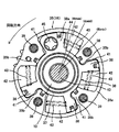
図2に示すリアビュー断面図において、ハウジング35(16)は、円筒状のハウジング本体35aの前端開口が円板状のフロントカバー17(図1参照)によって閉塞されていると共に、後端開口が円盤状のリアカバー18(図1参照)によって閉塞されている。また、ハウジング本体35aの内周面の周方向の約90°位置には、4つの隔壁であるシュー35bが内方に向かって突設されている。
リアカバー18は、タイミングスプロケット13の中央位置に両者一体に設けられ、外周部が4本のボルト39によってハウジング本体35aとフロントカバー17に共締め固定されている。また、リアカバー18のほぼ中央には、ベーンロータ36の円筒部に外周に軸受される大径な軸受孔が軸方向に貫通形成されている。
ベーンロータ36は、中央にボルト挿通孔を有する円筒状のロータ37と、ロータ37の外周面の周方向のほぼ90°位置に一体に設けられた4枚のベーン38、38aとを備えている。ロータ37は、前端側の小径筒部がフロントカバー17の中央支持孔に回転自在に支持されている一方、後端側の小径な円筒部がリアカバー18の軸受孔に回転自在に支持されている。
また、ベーンロータ36は、ロータ37のボルト挿通孔に軸方向から挿通した固定ボルト40によって排気カム軸10の前端部に軸方向から固定されている。また、各ベーン38、38aは、各シュー35b間に配置されていると共に、各外面の軸方向に形成された細長い保持溝内に前記ハウジング本体35aの内周面に摺接するシール部材及びこのシール部材をハウジング本体内周面方向に押圧する板ばねがそれぞれ嵌着、保持されている。
また、この各ベーン38、38aの両側と各シュー35bの両側面との間に、それぞれ4つの遅角室41と進角室42がそれぞれ隔成されている。尚、ベーン38aは、進角側のストッパ機能と、遅角側のストッパ機能を備えている。
そして、排気電磁切換弁31の切り換え作動によって、夫々の遅角室41と夫々の進角室42に作動油を選択的に供給することによって、ベーンロータ36(排気カム軸10)をクランクシャフトに対して相対回転位相を変更させるようになっている。また、各進角室42内には、ベーンロータ36を進角方向へ常時付勢する4本のコイルスプリング43が装着されている。
同様に、吸気VTC24も同じ構成となっているが、進角室及び遅角室が逆の関係となっており、ベーンロータ36を遅角方向へ常時付勢する4本のコイルスプリングが遅角室にそれぞれ装着されている。
図2において、ベーン38aのストッパ面44が進角時期(Emax)と一致した状態で、ベーン38aの他方側面とシュー35b側面が当接し最進角の位相となっている。また、ベーン38aのストッパ面44が遅角時期(Emin)と一致した状態でストッパ面44の当接により最遅角の位相となっている。ここで、進角室42に収納されたコイルスプリング43は、図2に示すようにベーン38a、38を進角側に付勢している。
ここで、中間角時期(Emid)は、最進角時期(Emax)と最遅角時期(Emin)の間にあり、最進角時期(Emax)よりやや遅角側にある。そして、この中間角時期(Emid)と一致した位相(デフォルト位相)では、ベーン38aに内蔵された締結ピン45とリアカバー18側の締結穴が一致し、デフォルト位置でベーン38a、38が位置決めされるようになっている。
また、吸気VTC24も図2に示す排気VTC14と同様な構造となっているが、最進角時期(Imax)と最遅角磁気(Imin)の間で形成される変換位相角が排気VTC14より大きく設定されている。
そして、排気VTC14と同様に、最進角時期(Imax)と最遅角時期(Imin)の間に設定され、ベーン内の締結ピンとリアカバー側の締結穴が一致する中間角時期(Imid)であるデフォルト位置は、最進角時期(Imax)より大きく遅角側に設定され、最遅角時期(Imin)よりやや進角側に設定されている。
したがって、ベーンのストッパ面が、この中間角時期(Imid)と一致した位相では、排気VTC14と同様にベーン内の締結ピンとリアカバー28側の締結穴が一致し、デフォルト位置でベーンが位置決めされるようになっている。
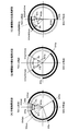
次に、本実施形態のバルブタイミング特性を説明するが、図3では「(A)冷機始動状態」と、「(B)暖機後の部分負荷状態」と、「(C)暖機後の全負荷状態」の夫々のバルブタイミング特性を示している。ここで、「(A)冷機始動状態」は、例えば内燃機関の本体温度が40℃以下の状態であり、また、「(B)暖機後の部分負荷状態」は、例えばアクセルペダルが中間付近程度まで踏み込まれた状態であり、更に、「(C)暖機後の全負荷状態」は、例えばアクセルペダルが最大付近程度まで踏み込まれた状態である。以下、夫々のバルブタイミング特性について説明する。≪冷機始動状態≫ 冷機始動時においては、図3の「(A)冷機始動状態」に示すバルブタイミング特性となる。ここでは、排気VTC14は上述の中間角時期(EVCc=Emid)で、ベーン38aが締結ピン45を介してリアカバー18と締結されるので、デフォルト位置となる。同様に、吸気VTC24のベーンも上述の中間角時期(IVOc=Imid)で、ベーンが締結ピンを介してリアカバーと締結されるので、デフォルト位置となる。
この結果、排気VTC14と吸気VTC24の両方がデフォルト位置となるので、排気バルブと吸気バルブのバルブタイミングは、図3の「(A)冷機始動状態」に示すバルブタイミングとなる。
つまり、排気バルブの閉時期(EVC)が、排気バルブの最進角閉時期(EVCadv)より遅角側で、しかも最遅角閉時期(EVCrtd)より進角側の間で、排気上死点(TDC)よりも所定角度(ETc)だけ進角側の排気バルブの閉時期(EVCc)に設定されている。ここで、最進角閉時期(EVCadv)は図2で示す最進角時期(Emax)と同じであり、最遅角閉時期(EVCrtd)は図2で示す最遅角時期(Emin)と同じである。
また、吸気バルブ開時期(IVO)は、吸気バルブの最遅角開時期(IVOrtd)より進角側で、しかも最進角開時期(IVOadv)より遅角側の間で、排気上死点(TDC)よりも所定角度(ITc)だけ遅角側の吸気バルブの開時期(IVOc)に設定されている。ここで、最進角開時期(IVOadv)は最進角時期(Imax)と同じであり、最遅角開時期(IVOrtd)は最遅角時期(Imin)と同じである。
この結果、冷間始動時においては、排気バルブの閉時期(EVCc)と吸気バルブの開時期(IVOc)の間には、所定角度(ITc)と所定角度(ETc)を足し合わせた「ITc+ETc」の角度からなる「負のバルブオーバーラップ」(NVOc)が設定されることになる。これによって、排気行程の末期から吸気行程の初期にかけて、高温燃焼ガス(高温EGRガス)が筒内に封じ込められ、且つピストンで加圧されることになる。
ここで、所定角度(ITc)と所定角度(ETc)は略同じ角度に設定されている。尚、略同じ角度とは、排気VTC14、及び吸気VTC24の組立後の機構的な誤差や設計上の公差等を含む概念であり、必ずしも同じ角度を意味するものではない。
したがって、冷機始動時において、「負のバルブオーバーラップ」(NVOc)の期間(排気行程の末期から吸気行程の初期にかけて)に、高温燃焼ガス(高温EGRガス)を筒内に封じ込め、しかもピストンで加圧することにより、圧縮上死点で残留している筒内ガスの温度を上昇させることができ、筒内ガス及びシリンダ本体が顕著に加熱されるようになる。
このため、次の吸気行程で新気を吸入した場合に形成される混合気の温度を高めることによって冷機始動時における燃焼を安定化して、燃費の向上や排気有害成分の発生を抑制でき、更に内燃機関の暖機性能(機関本体温度の上昇)を向上できるので、オイル粘度低下によって機構系の摩擦抵抗を低減して燃費性能を向上でき、また、排気系に備えられた排気浄化用触媒の温度を早く高める効果も得られるので、更に排気有害成分の低減効果が得られるものとなる。
尚、吸気バルブの閉時期(IVCc)を従来の閉時期(IVC)と同じに設定した場合、本実施形態では吸気バルブの開時期(IVOc)が遅角されているので、吸気バルブの開弁期間(吸気作動角)を狭く設定でき、これによって吸気バルブの動弁摩擦抵抗を減少して、内燃機関の駆動力が無駄に使用されるのを抑制することができる。
同様の理由で、排気バルブ開時期(EVOc)を従来の開時期(EVO)と同じに設定した場合、本実施形態では排気バルブの閉時期(EVCc)が進角されているので、排気バルブの開弁期間(排気作動角)を狭く設定でき、これによって排気バルブの動弁摩擦抵抗を減少して、内燃機関の駆動力が無駄に使用されるのを抑制することができる。
このようなことから、燃費性能を向上することが可能となる。更には、排気バルブの開時期(EVO)を可及的に早めることで、燃焼ガス温度が低下しないうちに排気バルブを開き、温度が高い排気ガスを排気ガス浄化用触媒に供給することで、排気ガス浄化用触媒の温度を高めて冷機始動時の排気ガス有害成分を低減することが、動弁摩擦抵抗の増加を抑制しつつ可能となる。
ここで、従来の「正のバルブオーバーラップ」(PVO)によっても筒内にEGRガスを導入することができるが、このEGRガスの温度は原理的に本実施形態による「負のバルブオーバーラップ」(NVO)よりは低くなり、また、吸気バルブ及び排気バルブの開弁期間(吸排作動角)も大きく設定されるので、吸気バルブ及び排気バルブの動弁摩擦抵抗が増加する課題を有している。
また、吸気バルブの開時期(IVOc)及び排気バルブの閉時期(EVCc)が、それぞれの最進角時期(IVOadv、EVCadv)最遅角時期(IVOrtd、EVCrtd)の間にあるので、暖機運転の途中や暖機後において、「負のバルブオーバーラップ」(NVO)を拡大したり、逆に減少させたりすることができ、これにより暖機運転途中及び暖機後において、種々の性能向上を実現することが可能となる。≪暖機後の部分負荷状態≫ 次に暖機後の部分負荷状態のバルブタイミングについて説明する。暖機後の部分負荷(低負荷)においては、図3の「(B)暖機後の部分負荷状態」に示すバルブタイミング特性となる。
すなわち、暖機後の部分負荷(低負荷)状態においては、吸気バルブの開時期(IVO)を、冷機始動状態の場合の吸気バルブの開時期(IVOc)より更に遅角側で、しかも排気上死点(TDC)よりも所定角度(ITp)だけ遅角側の開時期(IVOp)に変換する。ここで、開時期(IVOp)は最遅角開時期(IVOrtd)と同じ開時期とされている。
また、これと同時に、吸気バルブの閉時期(IVC)を吸気下死点(BDC)と圧縮上死点(TDC)の中間位置付近まで遅角した吸気バルブの閉時期(IVCp)に設定する。これは、例えば、吸気VTC24によってベーンを上述の吸気バルブの最遅角開時期(Imin)まで位相変換すれば良いものである。
また、暖機後の部分負荷(低負荷)状態においては、排気バルブの閉時期(EVC)を、冷機始動状態の場合の排気バルブの閉時期(EVCc)より更に進角側で、しかも排気上死点(TDC)よりも所定角度(ETp)だけ進角側の閉時期(EVCp)に変換する。ここで、閉時期(EVCp)は最進角閉時期(EVCadv)と同じ閉時期とされている。
また、これと同時に、排気バルブの開時期(EVO)を排気下死点(BDC)と圧縮上死点(TDC)の中間位置の間の区間まで進角して排気バルブの開時期(EVOp)に設定する。これは、例えば、排気VTC14によってベーン38a、38を上述の排気バルブの最進角時期(Emax)まで位相変換すれば良いものである。
これによって、冷機始動状態の場合の「負のバルブオーバーラップ」(NVOc)より更に長い、所定角度(ITp)と所定角度(ETp)を足し合わせた「ITp+ETp」の角度からなる「負のバルブオーバーラップ」(NVOp)が設定されることになる。したがって、排気行程の末期から吸気行程の初期にかけて、高温燃焼ガス(高温EGRガス)を筒内に封じ込め、しかもピストンで加圧することができる。
このため、内燃機関の暖機後の部分負荷(低負荷)における燃費効率を充分に向上することが可能となる。すなわち、暖機後の部分負荷(低負荷)においては、内燃機関の機構系の摩擦抵抗が冷機状態時より低減することもあり、吸入空気量を冷機状態時より低減することができるが、その場合にスロットルバルブを閉じて吸入空気量を低減すると、いわゆるポンプ損失が増加して燃費性能が悪化してしまう恐れがある。
そこで、吸気バルブの閉時期(IVC)を吸気下死点と圧縮上死点の中間位置付近まで大きく遅角して、いわゆる「遅閉じアトキンソンサイクル」とすることで、スロットルバルの開度を大開度に維持しつつ、吸入空気量を低減することが考えられる。
しかしながら、その場合には、吸気バルブの閉時期(IVC)が遅角されているので有効圧縮比が下がり、圧縮上死点でのガス温度が低下して燃焼の悪化が生じて所望の燃費低減効果が得られない恐れがある。
それに対し、本実施形態では、大きな「負のバルブオーバーラップ」(NVOp)によって圧縮上死点でのガス温度を上昇することができるので、この様な燃焼の悪化が回避されて所望の燃費低減効果が得られるようになる。
また、大きな「負のバルブオーバーラップ」(NVOp)により、筒内における高温燃焼ガスが相対的に増えることによって新気の量が相対的に減少されるので、所定の部分負荷トルクを得るのに必要なスロットル開度をさらに拡大でき(図5に示すスロットル大開度θp域)、これによってポンプ損失を更に低減できて燃費効率を向上することができるようになる。
尚、吸気バルブの閉時期(IVCp)を従来の閉時期(IVC)と同じに設定した場合、本実施形態では吸気バルブの開時期(IVOp)が遅角されているので、吸気バルブの開弁期間(吸気作動角)を狭く設定でき、これによって吸気バルブの動弁摩擦抵抗を減少して、内燃機関の駆動力が無駄に使用されるのを抑制することができ、結果として燃費性能を向上することが可能となる。
同様の理由で、排気バルブ開時期(EVOp)を従来の開時期(EVO)と同じに設定した場合、本実施形態では排気バルブの閉時期(EVCp)が進角されているので、排気バルブの開弁期間(排気作動角)を狭く設定でき、これによって排気バルブの動弁摩擦抵抗を減少して、内燃機関の駆動力が無駄に使用されるのを抑制することができ、結果として燃費性能を向上することが可能となる。
ここで、本実施形態では、特に所定角度(ITp)と所定角度(ETp)が、略同じ角度になるように設定されている。これによれば、「負のバルブオーバーラップ」(NVOp)の間に発生する、ポンプ損失を低減できるようになる。その理由について図4に示すPV線図を用いて説明する。
ここで、所定角度(ITp)と所定角度(ETp)は略同じ角度に設定されているが、上述の通り略同じ角度とは、排気VTC14、及び吸気VTC24の組立後の機構的な誤差や設計上の公差等を含む概念であり、必ずしも同じ角度を意味するものではない。
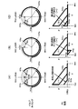
図4の(A)は、本実施形態(図3の(B)に示すバルブタイミング特性)のPV線図を示し、図4の(B)は、比較対象としての参考例1(ETp≒0<ITp)でのPV線図を示し、図4の(C)は、同じく比較対象としての参考例2(ETp>ITp≒0)でのPV線図を示している。
図4の(B)の参考例1においては、排気上死点(TDC)からピストンが下がっていく過程で、吸気バルブの開時期(IVOp)までの区間(ITp)は筒内負圧が発達する。そして、この筒内負圧はピストンの下降動作を抑制するように作用するので、PV線図に示すように吸入初期のポンプ損失(下向き三角領域)が発生する。
また、図5の(C)の参考例2においては、排気上死点(TDC)前の排気バルブが閉じる閉時期(EVCp)から排気上死点(TDC)に向けてピストンが上昇していく過程で、排気上死点(TDC)までの区間(ETp)は筒内正圧が発達する。そして、この筒内正圧はピストンの上昇動作を抑制するように作用する。ここで、排気上死点(TDC)を越えると吸気バルブが開くので、この筒内の正圧ガスは吸気側に逆流してしまい、ピストンの下降動作を助長するためのエネルギとして回収することができない。その結果、(C)のPV線図に示すように、排気行程の末期のポンプ損失(上向き三角領域)が発生する。
このように、参考例1、2ともポンプ損失が大きくなるので部分負荷での燃費の悪化を生じるようになるものである。
これに対して、本実施形態においては、図4(A)のPV線図に示すように、吸気行程の初期のポンプ損失、及び排気行程の末期のポンプ損失とも抑制することができる。
つまり、参考例2と同様に、排気バルブの閉時期(EVCp)が排気上死点(TDC)前であり、排気バルブの閉時期(EVCp)から排気上死点(TDC)にかけて、高温燃焼ガス(高温EGRガス)が所定角度(ETp)分だけ圧縮されて、その時点ではピストンの上昇動作を抑止しようと作用する。
一方、吸気バルブの開時期(IVOp)が排気上死点(TDC)から同じ角度で、所定角度(ITp)分だけ遅れているので、排気上死点(TDC)を越えてピストンが下降動作に移ると、先に圧縮された高温燃焼ガスの圧力が開放されてピストンの下降動作を助長するエネルギとして回収されるようになる。その結果、図4(A)に示すように、三角形の面積の発生が抑制され、排気上死点(TDC)前後のポンプ損失が抑制されるのである。
したがって、所定角度(ETp)=所定角度(ITp)の関係が最も好ましく、図4の(A)のPV線図に示すように、排気行程の末期のポンプ損失と吸気行程の初期のポンプ損失の両方を除去できるようになる。このように、図4の(A)に示す本実施形態の部分負荷状態でのバルブタイミング特性は、排気上死点(TDC)前後のポンプ損失を抑制するという観点でも、更に燃費性能を向上できるものである。≪暖機後の全負荷状態≫ 次に暖機後の全負荷状態のバルブタイミングについて説明する。暖機後の全負荷においては、図3の「(C)暖機後の全負荷状態」に示すバルブタイミング特性となる。
すなわち、暖機後の全負荷状態においては、吸気VTC24のストッパ面は最進角時期(Imax)まで最大限の進角変換が行われる。このため吸気気バルブの開時期(IVO)は、冷機始動状態の場合の吸気バルブの開時期(IVOc)より大幅に進角側に進角され、しかも排気上死点(TDC)よりも所定角度(ITh)だけ進角側の開時期(IVOh)に変換される。ここで、開時期(IVOh)は最進角開時期(IVOadv)と同じ開時期とされている。
また、暖機後の全負荷状態においては、排気VTC14のストッパ面44は最遅角時期(Emin)まで最大限の遅角変換が行われる。排気バルブの閉時期(EVC)を、冷機始動状態の場合の排気バルブの閉時期(EVCc)より大幅に遅角側に遅角され、しかも排気上死点(TDC)よりも所定角度(ETh)だけ遅角側の閉時期(EVCh)に変換される。ここで、閉時期(EVCh)は最進角閉時期(EVCrtd)と同じ閉時期とされている。
したがって、吸気バルブの開時期(IVOh)が最大進角開時期(IVOadv)となり、排気バルブの閉時期(EVCh)が最大遅角閉時期(EVCrtd)となるので、大きな「正のバルブオーバーラップ」(PVOh)が設定される。また、吸気バルブの閉時期(IVCh)は吸気下死点付近まで進角し、排気バルブの開時期(EVOh)は膨張下死点付近まで遅角する。ここで、吸気VTC24の進角変換角は、排気VTC14の遅角変換角より大きく、その結果、上述の「正のバルブオーバーラップ」(PVOh)の区間中心は、図3の(C)に示すように、排気上死点(TDC)より進角することになる。
そして、このようなバルブタイミング特性によれば、暖機後の全負荷状態における機関トルクを充分に高めることが可能となる。すなわち、排気バルブの開時期(EVOh)が膨張下死点(BDC)付近まで遅角されたので、排気脈動の負圧波が排気バルブ付近に到来するタイミングが、「正のバルブオーバーラップ」(PVOh)の近くまで遅れるようになる。
このため、負圧波によって開状態の排気バルブを介して筒内の高温燃焼ガスを吸い出し、そこに冷たい新気が、開状態の吸気バルブを介して筒内に導入される、という所謂掃気効果が得られる。これによって、全負荷状態での吸気充填効率が高まるだけでなく、筒内を新気により冷却するので、いわゆる耐ノッキング性も向上して、両者の効果により機関トルクの絶対値を高めることができるようになる。
さらに、「正のバルブオーバーラップ」(PVOh)の区間中心が、排気上死点(TDC)より進角しているので、排気脈動の負圧波が「正のバルブオーバーラップ」(PVOh)と同期しやすくなり、上記掃気効果を大きくすることができる。つまり、排気脈動の負圧波が排気バルブ付近に到来するタイミングを、「正のバルブオーバーラップ」(PVOh)の区間中心に近づけることができる。
また、本実施形態では内燃機関の筒内で燃焼される混合気は、冷機時や暖機後の部分負荷状態では、リーン状態の混合気としても良い。その場合、空燃比が理論空燃比よりリーン状態であるのでエンジン本体からの排気有害成分の発生が少ない、さらに燃費性能が向上する、といった長所があるが、燃焼の安定性に課題がある。ところが、本実施形態においては、前述のNVOの効果によって燃焼の安定性が向上できるので、リーン状態の混合気を使用する長所を十分に発揮することができるようになる。
次に運転条件(状態)を変化させた場合のバルブオーバーラップの変化とスロットルバルブの開度変化を図5に基づき説明する。
上述してきたように、冷機運転状態(冷機始動後のファ-ストアイドル等)では、中程度の「負のバルブオーバーラップ」(NVOc)により、冷機運転時の燃焼の安定化や暖機性能の向上等により、燃費性能の向上や排気ガス有害成分を低減する。その際、冷機運転時だと、内燃機関の機構系の摩擦抵抗が大きいので、この摩擦抵抗に打ち勝つためにスロットルバルブの開度θcは大開度として機関トルクを高めている。
また、暖機後のアイドルでは、冷機運転時のバルブタイミングが維持されている。つまり、例えば、暖機後アイドルの「負のバルブオーバーラップ」(NVOi)は、冷機運転時の「負のバルブオーバーラップ」(NVOc)と一致させている。ここで、暖機後は内燃機関の機構系の摩擦抵抗が小さくなっているので、燃焼トルクを下げるために、スロットルバルブの開度を小開度θiまで閉じている。
これによって、大きな吸気負圧が生じてポンプ損失は増加するが、暖機後のアイドルであるため、少吸入空気量(小燃焼トルク)であるが故の燃焼変動・回転変動をこの負圧による燃料霧化改善効果により高め、その結果、アイドルでの燃焼安定性、回転安定性、燃費性能等を向上することができる。
ここで、仮に通常の「正バルブオーバーラップ」(PVO)であると、スロットルバルブの開度を小さくしたことによって増加した吸気負圧が、開状態の吸気バルブを介して筒内の内部EGRを吸気系に吸いだしたり、さらにはこの吸気負圧が「正バルブオーバーラップ」(PVO)の区間に開状態の排気バルブを介して排気ポ-ト側から排気ガスを筒内に再吸入してしまう。そして、吸気系に吸い出された内部EGRが次の吸気行程において再度筒内に導入され、さらに前述のような排気ポート側から筒内に導入される内部EGRも付加されて、最終的に筒内に導入される内部EGRが過大となり燃焼安定性が悪くなるという問題がある。
それに対し、本実施形態では「負のバルブオーバーラップ」(NVOi)になっているので、吸気バルブと排気バルブが同時に開くことがなく、また排気上死点付近では吸気バルブ、排気バルブとも開いておらず、吸気負圧が高まった暖機後アイドルにおいても、前述のPVOの場合のように筒内に過大な内部EGRが導入されることはなく、安定した良好な燃焼状態を実現できるようになる。
したがって、例えば、図5の「負のバルブオーバーラップ」(NVOi´)に示すように、バルブオーバーラップを「0」にしなくても良く、暖機後の部分負荷状態での「負のバルブオーバーラップ」(NVOp)から暖機後のアイドル状態の「負のバルブオーバーラップ」(NVOi)の変化幅を抑制できる。これによって、機関運転条件が両領域を行き交う運転状態の吸気VTC24と排気VTC14の変換応答遅れの問題を回避できる。
また、暖機後の部分負荷状態では、大きな「負のバルブオーバーラップ」(NVOp)による高温混合ガスにより燃焼を安定化できることに加え、アトキンソンサイクルの実施や、ポンプ損失の低減等により燃費性能を向上する。この場合、大きな「負のバルブオーバーラップ」(NVOp)やアトキンソンサイクル(吸気バルブ遅閉じ)の実施により、スロットルバルブの開度を絞らずに充填効率(トルク)を抑制できるので、スロットルバルブの開度は大開度θpとなっている。
また、暖機後の全負荷状態では、暖機後の全負荷状態における機関トルクを充分に高めることが可能となる。すなわち、排気バルブの開時期(EVOh)が膨張下死点(BDC)付近まで遅角されたので、排気脈動の負圧波が排気バルブ付近に到来するタイミングが、「正のバルブオーバーラップ」(PVOh)の近くまで遅れる。このため、負圧波によって開状態の排気バルブを介して筒内の高温燃焼ガスを吸い出し、そこに冷たい新気が、開状態の吸気バルブを介して筒内に導入される。これによって、全負荷状態での吸気充填効率が高まり、更に筒内を新気により冷却するので耐ノッキング性能も向上して、両者の効果により充分に機関トルクの絶対値を高めることができるようになる。
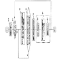
次に、上述した本実施形態になるバルブタイミング特性を実行するための制御フローについて説明する。尚、この制御フローは制御装置30によって実行されるものである。図6には、内燃機関を停止する停止移行時に、排気VTC14と吸気VTC24を「負のバルブオーバーラップ(NVOc)となるデフォルト位置に機械的に安定させる制御フローを示している。
≪ステップS10≫まず、ステップS10においては、内燃機関を停止する機関停止情報や、内燃機関の運転条件情報を読み込む。内燃機機関を停止する機関停止情報としては、代表的にはキーオフ信号があり、また、内燃機関の運転条件情報を示す信号としては数多くあるが、本実施形態では、内燃機関の回転数情報、吸気量情報、水温情報、要求負荷情報(アクセル開度)等があり、更に排気VTC14や吸気VTC24の実位置情報等がある。このステップS10で各種情報を読み込むとステップS11に移行する。
≪ステップS11≫ステップS11においては、機関停止移行条件かどうかを判断する。この判断は、例えば、キーオフ信号を監視しておけばよく、キーオフ信号が入力されないとリターンに抜けて次の起動タイミングを待つことになる。一方、キーオフ信号が入力されると、機関停止移行条件と判断してステップS12に移行する。
≪ステップS12≫ステップS12においては、排気VTC14、及び吸気VTC24にデフォルト位置に移行するように、変換制御信号を排気VTC14の排気電磁切換弁31、及び吸気VTC24の吸気電磁切換弁32に出力する。つまり、次回の始動に対応するために、図3の「(A)冷機始動状態」のバルブタイミング特性になるように油圧を制御するものである。
したがって、排気バルブの閉時期(EVC)は、図3の「(A)冷機始動状態」の排気バルブの閉時期(EVCc=Emid:図2参照)に設定され、また、吸気バルブ開時期(IVO)は、吸気バルブの開時期(IVOc=Imid:同様図2参照)に設定されるものである。これによって「負のバルブオーバーラップ」(NVOc)が設定されることになる。変換制御信号を排気VTC14の排気電磁切換弁31、及び吸気VTC24の吸気電磁切換弁32に出力すると、ステップS13に移行する。
≪ステップS13≫ステップ13においては、排気VTC14及び吸気VTC24の実位置情報から、排気VTC14及び吸気VTC24がデフォルト位置に移行したか、つまり、排気バルブの閉時期(EVCc)に設定され、また、吸気バルブの開時期(IVOc)に設定されたかどうかが判断される。そして、排気バルブの閉時期(EVCc)、及び吸気バルブの開時期(IVOc)に設定されていないと判断されると、再びステップS12に戻り、排気バルブの閉時期(EVCc)、及び吸気バルブの開時期(IVOc)に設定されたと判断されるとステップS14に移行する。
≪ステップS14≫ステップS14においては、内燃機関を停止するため燃料噴射弁や点火装置への出力制御信号を停止する。これによって内燃機関の回転数Neが低下していき、これに伴って油圧ポンプの作動油の油圧が低下することになる。内燃機関が停止されると、排気VTC14及び吸気VTC24は、以下の動作をその機構に基づいて実行する。この動作は、フローチャートでいう制御ステップではないが、便宜上制御ステップとして説明する。
≪ステップS15~ステップS17≫内燃機関の回転数Neの低下に伴い、油圧ポンプからの作動油の吐出圧も下がるので、排気VTC14、及び吸気VTC24のベーン内に保持されていた締結ピン45(図2参照)は、リタ-ンスプリングによりリアカバー方向に移動する。一方、排気VTC14、及び吸気VTC24の進角室、遅角室には作動油が充満されており、回転数Neが下がってもベーン位置はそのまま維持されている。
そして、リタ-ンスプリングによって締結ピンが、リアカバー方向に更に移動して締結穴に締結することで、ベーンはハウジングに固定され、排気バルブの閉時期(EVCc)、及び吸気バルブの開時期(IVOc)のデフォルト位置に最終的に決定される。ここで、締結ピンの先端はテ-パ形状に形成されており、ベーンの位相が多少ずれていても締結ピンを締結穴に係合させることができる。そして内燃機関は回転数Ne=0となって機関停止となるものである。
このようにして、内燃機関を停止する停止移行時に、排気VTC14と吸気VTC24を、「負のバルブオーバーラップ(NVOc)が得られる、排気バルブの閉時期(EVCc)と吸気バルブの開時期(IVOc)のデフォルト位置に機械的に安定させることができるようになるものである。
次に、この状態から内燃機関の運転を再開する場合の制御フローを図7に基づき説明する。この制御フローも制御装置30によって実行されるものである。
≪ステップS20≫まず、ステップS20においては、内燃機関を始動する機関始動情報や、内燃機関の運転条件情報を読み込む。内燃機機関を始動する機関始動情報としては、代表的にはキーオン信号、或いはスタータ起動信号があり、また、内燃機関の運転条件情報を示す信号としては数多くあるが、本実施形態では、内燃機関の回転数情報、吸気量情報、水温情報、要求負荷情報(アクセル開度)等があり、更に排気VTC14や吸気VTC24の実位置情報等がある。このステップS20で各種情報を読み込むとステップS21に移行する。
≪ステップS21≫ステップS21においては、機関始動条件かどうかを判断する。この判断は、例えば、スタータ起動信号を監視しておけばよく、スタータ起動信号が入力されないとリターンに抜けて次の起動タイミングを待つことになる。一方、スタータ起動信号が入力されると、機関始動条件と判断してステップS22に移行する。
≪ステップS22≫ステップS22においては、スタータ起動信号を受けてスタータモータによる内燃機関のクランキングを開始する。そして、クランキングが開始されるや否やステップS23に移行する。
≪ステップS23≫ステップS23においては、排気VTC14及び吸気VTC24にデフォルト位置に移行するように、変換制御信号を排気VTC14の排気電磁切換弁31、及び吸気VTC24の吸気電磁切換弁32に出力する。これは、油圧ポンプの作動油の油圧が上昇した時に、何らかの原因で締結ピンが締結穴から抜けて締結状態が解除されても、排気VTC14及び吸気VTC24のベーンをデフォルト位置に維持しておくための制御である。そして、変換制御信号を排気VTC14の排気電磁切換弁31、及び吸気VTC24の吸気電磁切換弁32に出力すると、ステップS24に移行する。
≪ステップS24≫ステップ24においては、排気VTC14及び吸気VTC24の実位置情報から、排気VTC14及び吸気VTC24がデフォルト位置に移行したか、つまり、排気バルブの閉時期(EVCc)に設定され、また、吸気バルブの開時期(IVOc)に設定されたかどうかが判断される。そして、排気バルブの閉時期(EVCc)、及び吸気バルブの開時期(IVOc)に設定されていないと判断されると、再びステップS23に戻り、排気バルブの閉時期(EVCc)、及び吸気バルブの開時期(IVOc)に設定されたと判断されるとステップS25に移行する。
≪ステップS25≫ステップS25においては、スタータモータの回転に合せて内燃機関を始動するため燃料噴射弁や点火装置へ出力制御信号を供給する。これによって内燃機関の回転数Neが増加していき、これに伴って油圧ポンプの作動油の油圧が上昇することになる。燃料噴射弁や点火装置へ出力制御信号を供給するとステップS26に移行する。
≪ステップS26≫ステップS26においては、内燃機関の機関温度(冷却水温度)を検出して所定温度T0を超えたかどうかを判断する。所定温度T0を超えていなければ冷機状態と判断してリターンに抜けて次の起動タイミングを待つことになる。この状態は冷機始動状態となる。したがって、図3の「(A)冷機始動状態」の排気バルブの閉時期(EVCc)、及び吸気バルブの開時期(IVOc)によって「負のバルブオーバーラップ」(NVOc)が設定されて、始動されることになる。
一方、所定温度T0を超えていれば冷機状態から暖機完了したと判断して、夫々の運転条件に応じて排気VTC14、及び吸気VTC24が制御マップに基づいて制御されることになる。したがって、所定温度T0を超えて暖機が完了していればステップS27に移行する。
≪ステップS27、ステップS28≫ステップS27においては、スロットルバルブの開度、或いはアクセルペダルの開度からアイドル条件かどうかを判断する。アイドル条件と判断されると、ステップS28に移行して、排気VTC14、及び吸気VTC24によって、アイドル時の排気バルブの閉時期(EVCi)、及び吸気バルブの開時期(IVOi)によってアイドル時の「負のバルブオーバーラップ」(NVOi)に制御するものである。一方、アイドル状態ではないと判断されるとステップS29に移行する。
≪ステップS29~ステップS30≫ステップS29においては、スロットルバルブの開度、或いはアクセルペダルの開度から部分負荷条件かどうかを判断する。部分負荷条件と判断されると、ステップS30に移行して、排気VTC14、及び吸気VTC24によって、部分負荷時の排気バルブの閉時期(EVCp)、及び吸気バルブの開時期(IVOp)によって、部分負荷時の「負のバルブオーバーラップ」(NVOp)に制御するものである。この部分負荷でのバルブタイミング特性は、図3の「(B)暖機後の部分負荷状態」に示すバルブタイミングである。一方、部分負荷状態ではないと判断されるとステップS31に移行する。
≪ステップS31~ステップS32≫ステップS31においては、スロットルバルブの開度、或いはアクセルペダルの開度から全負荷条件かどうかを判断する。全負荷条件と判断されると、ステップS32に移行して、排気VTC14、及び吸気VTC24によって、全負荷時の排気バルブの閉時期(EVCh)、及び吸気バルブの開時期(IVOh)によって、全負荷時の「正のバルブオーバーラップ」(PVOh)に制御するものである。この全負荷でのバルブタイミング特性は、図3の「(C)暖機後の全負荷状態」に示すバルブタイミングである。一方、全負荷状態ではないと判断されるとリターンに抜けて次の起動タイミングを待つことになる。
このようにして、本実施形態では、広い運転範囲で燃焼状態を安定な状態に管理できるバルブタイミング特性を得ることができ、排気有害成分の発生を抑制し、しかも燃費性能の向上を図ることができるようになる。
次に、本発明の第2の実施形態について、図8を用いて説明する。第1の実施形態では、排気バルブと吸気バルブの作動角が一定で、バルブリフトが不変の排気VTC14と吸気VTC24を使用した。これに対して、第2の実施形態は、排気側と吸気側の両方に、作動角と開閉時期を連続的に調整することが可能なバルブリフト可変動弁機構を用いた点で異なっている。
本実施形態では、排気バルブリフト可変動弁機構(以下、排気VELと表記する)と、吸気バルブリフト可変動弁機構(以下、吸気VELと表記する)とを用いて、夫々のバルブの開時期、閉時期、及び作動角を調整するものである。
そして、冷機始動状態においては、吸気VELで作動角を縮小して、図8の「(A)冷機始動状態」のようなバルブタイミング特性が設定される。第1の実施形態の図3の「(A)冷機始動状態」として比較して分かるように、吸気バルブの閉時期(IVC)が、閉時期(IVCc´)というように下死点付近まで進角されている。これによって、第1の実施形態と比較して、有効圧縮比が高まるので燃焼状態が改善されて、排気ガス中の排気有害成分が更に低減できるという効果がある。
また、暖機後の部分負荷状態においては、吸気VELで作動角を拡大して、図8の「(B)暖機後の部分負荷状態」のようなバルブタイミング特性が設定される。第1の実施形態の図3の「(B)暖機後の部分負荷状態」として比較して分かるように、吸気バルブの閉時期(IVC)が、閉時期(IVCp´)というように上死点側まで遅角されている。これによって、第1の実施形態と比較して、アトキンソンサイクルの効果が高まるので、燃費性能を更に向上できるという効果がある。
更に、暖機後の全負荷状態においては、排気VELで作動角を縮小して、図8の「(C)暖機後の全負荷状態」のようなバルブタイミング特性が設定される。第1の実施形態の図3の「(C)暖機後の全負荷状態」として比較して分かるように、排気バルブの閉時期(EVC)が、閉時期(EVCh´)というように上死点側まで進角されている。これは、第1の実施形態と比較して、「正のオーバーラップ」(PVO)における遅角側の一部が除去された形となっている。この付近では、排気脈動が負圧から正圧に戻りだしており、この部分を除去すれば、この戻り正圧による掃気効果の目減りを抑えることができ、掃気効果を更に高めることができるという効果がある。
このように、排気VEL、及び吸気VELを採用することによって本発明の効果を更に高めることが可能となる。
以上の第2の実施形態では、排気側と吸気側の両方に、作動角と開閉時期を連続的に調整することが可能なバルブリフト可変動弁機構を用いているが、一方をバルブリフト可変動弁機構とし、他方を作動角が一定で、バルブリフトが不変の位相可変動弁機構(上述のVTC)とすることも可能である。
更に、可変動弁機構の形態として、油圧駆動式の位相可変機構(吸/排気VTC)を示したが、油圧駆動に限らず電動駆動式の位相可変機構でも使用することができる。また、可変動弁機構の形態として、作動角と開閉時期が連続変化する吸/排気VELの例を示したが、作動角を段階的に調整する吸/排気VVLのようなものも使用することができる。要は、本発明の主旨を満足するものであれば、具体的な可変動弁機構の形態は限定されないものである。
以上述べた通り、本発明によれば、内燃機関の冷機始動時には、吸気バルブ可変動弁機構によって吸気バルブの開時期(IVOc)を、最遅角開時期(IVOrtd)より進角側で、しかも最進角開時期(IVOadv)より遅角側の間で、排気上死点(TDC)よりも所定角度(ITc)だけ遅角側に設定すると共に、排気バルブ可変動弁機構によって排気バルブの閉時期(EVCc)を、最進角閉時期(EVCadv)より遅角側で、しかも最遅角時期(EVCrtd)より進角側の間で、排気上死点(TDC)よりも所定角度(ETc)だけ進角側に設定して、吸気バルブの開時期(IVOc)と排気バルブの閉時期(EVCc)とが重ならない「負のバルブオーバーラップ」(NVOc)を形成する構成とした。
これによれば、内燃機関の冷機始動時において、排気行程の末期から吸気行程の初期にかけて「負のバルブオーバーラップ」(NVOc)を形成することによって、高温燃焼ガス(高温EGRガス)を筒内に封じ込め、しかもピストンで加圧することにより、残留している筒内ガス及び機関本体が加熱されて、冷機始動時における燃焼の悪化を抑制して排気ガス中の排気有害成分を低減することができるようになる。
尚、本発明は上記した実施形態に限定されるものではなく、様々な変形例が含まれる。例えば、上記した実施形態は本発明を分かりやすく説明するために詳細に説明したものであり、必ずしも説明した全ての構成を備えるものに限定されるものではない。また、ある実施形態の構成の一部を他の実施形態の構成に置き換えることが可能であり、また、ある実施形態の構成に他の実施形態の構成を加えることも可能である。また、各実施形態の構成の一部について、他の構成の追加・削除・置換をすることが可能である。
本願は、2017年2月28日付出願の日本国特許出願第2017-035878号に基づく優先権を主張する。2017年2月28日付出願の日本国特許出願第2017-035878号の明細書、特許請求の範囲、図面、及び要約書を含む全開示内容は、参照により本願に全体として組み込まれる。
10…排気カム軸、11…排気カム、12…排気バルブ、13…スプロケット機構、14…排気バルブ可変動弁機構(排気VTC)、15…タイミングスプロケット、16(35)…ハウジング、17…フロントカバー、18…リアカバー、20…吸気カム軸、21…吸気カム、22…吸気バルブ、23…スプロケット機構、24…吸気バルブ可変動弁機構(吸気VTC)、25…タイミングスプロケット、26…ハウジング、27…フロントカバー、28…リアカバー、30…制御装置、31…排気電磁切換弁、32…吸気電磁切換弁、IVOc…冷間始動時の吸気バルブの開時期、EVCc…冷間始動時の排気バルブの閉時期、IVOadv…吸気バルブの最進角時期、IVOrtd…吸気バルブの最遅角時期、EVCadv…排気バルブの最進角時期、EVCrtd…排気バルブの最遅角時期。
Claims (13)
- 動弁制御系を備えた内燃機関の可変動弁システムであって、
前記動弁制御系は、少なくとも、
吸気バルブの開閉時期を調整する吸気バルブ可変動弁機構と、
排気バルブの開閉時期を調整する排気バルブ可変動弁機構と、
前記吸気バルブ可変動弁機構、及び前記排気バルブ可変動弁機構を制御する制御手段とを備えており、
前記動弁制御系は、内燃機関の冷機始動時においては、
前記吸気バルブ可変動弁機構によって、吸気バルブの開時期(IVO)を、最遅角開時期(IVOrtd)より進角側で、しかも最進角開時期(IVOadv)より遅角側の間で、排気上死点(TDC)よりも所定角度(ITc)だけ遅角側の吸気バルブの開時期(IVOc)に設定し、
前記排気バルブ可変動弁機構によって、排気バルブの閉時期(EVC)を、最進角閉時期(EVCadv)より遅角側で、しかも最遅角時期(EVCrtd)より進角側の間で、排気上死点(TDC)よりも所定角度(ETc)だけ進角側の排気バルブの閉時期(EVCc)に設定して、
前記吸気バルブの開時期(IVOc)と前記排気バルブの閉時期(EVCc)とが重ならない「負のバルブオーバーラップ」(NVOc)を形成することを特徴とする内燃機関の可変動弁システム。 - 請求項1に記載の内燃機関の可変動弁システムにおいて、
前記所定角度(ITc)と前記所定角度(ETc)とは、略同じ角度であることを特徴とする内燃機関の可変動弁システム。 - 請求項1に記載の内燃機関の可変動弁システムにおいて、
前記動弁制御系は、前記内燃機関の暖機後の部分負荷時においては、
前記吸気バルブ可変動弁機構によって、前記吸気バルブの開時期(IVO)を、前記吸気バルブの閉時期(IVOc)より遅角側で、しかも前記排気上死点よりも所定角度(ITp)だけ遅角側の吸気バルブの開時期(IVOp)に設定すると共に、吸気バルブの閉時期(IVC)を、吸気下死(BDC)点と圧縮上死点(TDC)の中間位置付近の吸気バルブの閉時期(IVCp)に設定し、
前記排気バルブ可変動弁機構によって、前記排気バルブの閉時期(EVC)を、前記排気バルブの閉時期(EVCc)より進角側で、しかも前記排気上死点(TDC)よりも所定角度(ETp)だけ進角側の排気バルブの閉時期(EVCp)に設定することを特徴とする内燃機関の可変動弁システム。 - 請求項3に記載の内燃機関の可変動弁システムにおいて、
前記所定角度(ITp)と前記所定角度(ETp)とは、略同じ角度であることを特徴とする内燃機関の可変動弁システム。 - 請求項1に記載の内燃機関の可変動弁システムにおいて、
前記動弁制御系は、前記内燃機関の暖機後の全負荷時においては、
前記吸気バルブ可変動弁機構によって、前記吸気バルブの開時期(IVO)を、前記吸気バルブの開時期(IVOp)より進角側の吸気バルブの開時期(IVOh)に設定し、
前記排気バルブ可変動弁機構によって、前記排気バルブの閉時期(EVC)を、前記排気バルブの閉時期(EVCp)より遅角側の排気バルブの閉時期(EVCh)に設定し、しかも排気バルブの開時期(EVO)を、膨張下死点(BDC)付近の排気バルブの開時期(EVOh)に設定して、
前記吸気バルブの開時期(IVOh)と前記排気バルブの閉時期(EVCh)とが重なる「正のバルブオーバーラップ」(PVOh)を形成することを特徴とする内燃機関の可変動弁システム。 - 請求項5に記載の内燃機関の可変動弁システムにおいて、
前記「正のバルブオーバーラップ」(PVOh)の期間中心が、前記排気上死点(TDC)より進角側に設定されていることを特徴とする内燃機関の可変動弁システム。 - 請求項1に記載の内燃機関の可変動弁システムにおいて、
前記吸気バルブ可変動弁機構は吸気側機械的安定位置を定める機構を備えており、前記吸気バルブの開時期(IVOc)は、前記吸気側機械的安定位置によって決められ、
前記排気バルブ可変動弁機構は排気側機械的安定位置を定める機構を備えており、前記排気バルブの閉時期(EVCc)は、前記排気側機械的安定位置によって決められることを特徴とする内燃機関の可変動弁システム。 - 請求項1に記載の内燃機関の可変動弁システムにおいて、
前記吸気バルブ可変動弁機構、及び前記排気バルブ可変動弁機構は、作動角が一定のまま前記開閉時期が変化する位相可変型の可変動弁機構であることを特徴とする内燃機関の可変動弁システム。 - 請求項1に記載の内燃機関の可変動弁システムにおいて、
前記吸気バルブ可変動弁機構、及び前記排気バルブ可変動弁機構の少なくとも一方は、作動角が一定のまま前記開閉時期が変化する位相可変型の可変動弁機構であり、他方は前記作動角と前記開閉時期が共に変化するバルブリフト可変型の可変動弁機構であることを特徴とする内燃機関の可変動弁システム。 - 請求項1に記載の内燃機関の可変動弁システムにおいて、
前記内燃機関に供給される混合気は、リーン状態の混合気であることを特徴とする内燃機関の可変動弁システム。 - 可変動弁機構のコントロール装置であって、
前記コントロール装置は、少なくとも、
吸気バルブの開閉時期を調整する吸気バルブ可変動弁機構と、排気バルブの開閉時期を調整する排気バルブ可変動弁機構とを制御する制御手段を備えており、
前記制御手段は、内燃機関の冷機始動時においては、
吸気バルブの開時期(IVO)を、最遅角開時期(IVOrtd)より進角側で、しかも最進角開時期(IVOadv)より遅角側の間で、排気上死点(TDC)よりも所定角度(ITc)だけ遅角側の吸気バルブの開時期(IVOc)に設定するように前記吸気バルブ可変動弁機構を制御する第1の機能と、
排気バルブの閉時期(EVC)を、最進角閉時期(EVCadv)より遅角側で、しかも最遅角時期(EVCrtd)より進角側の間で、排気上死点(TDC)よりも所定角度(ETc)だけ進角側の排気バルブの閉時期(EVCc)に設定するように前記排気バルブ可変動弁機構を制御する第2の機能を有し、
前記第1の機能と前記第2の機能を実行することによって、前記吸気バルブの開時期(IVOc)と前記排気バルブの閉時期(EVCc)とが重ならない「負のバルブオーバーラップ」(NVOc)を形成することを特徴とする可変動弁機構のコントロール装置。 - 請求項11に記載の可変動弁機構のコントロール装置において、
前記制御手段は、前記内燃機関の暖機後の部分負荷時においては、前記吸気バルブの開時期(IVO)を、前記吸気バルブの閉時期(IVOc)より遅角側で、しかも前記排気上死点よりも所定角度(ITp)だけ遅角側の吸気バルブの開時期(IVOp)に設定すると共に、吸気バルブの閉時期(IVC)を、吸気下死(BDC)点と圧縮上死点(TDC)の中間位置付近の吸気バルブの閉時期(IVCp)に設定するように前記吸気バルブ可変動弁機構を制御する第3機能と、
前記排気バルブの閉時期(EVC)を、前記排気バルブの閉時期(EVCc)より進角側で、しかも前記排気上死点(TDC)よりも所定角度(ETp)だけ進角側の排気バルブの閉時期(EVCp)に設定するように前記排気バルブ可変動弁機構を制御する第4機能を有している、ことを特徴とする可変動弁機構のコントロール装置。 - 請求項11に記載の可変動弁機構のコントロール装置において、
前記制御手段は、前記内燃機関の暖機後の全負荷時においては、
前記吸気バルブの開時期(IVO)を、前記吸気バルブの開時期(IVOp)より進角側の吸気バルブの開時期(IVOh)に設定するように前記吸気バルブ可変動弁機構を制御する第5の機能と、
前記排気バルブの閉時期(EVC)を、前記排気バルブの閉時期(EVCp)より遅角側の排気バルブの閉時期(EVCh)に設定し、しかも排気バルブの開時期(EVO)を、膨張下死点(BDC)付近の排気バルブの開時期(EVOh)に設定するように前記排気バルブ可変動弁機構を制御する第6の機能を有し、
前記第5の機能と前記第6の機能を実行することによって、前記吸気バルブの開時期(IVOh)と前記排気バルブの閉時期(EVCh)とが重なる「正のバルブオーバーラップ」(PVOh)を形成することを特徴とする可変動弁機構のコントロール装置。
Applications Claiming Priority (2)
| Application Number | Priority Date | Filing Date | Title |
|---|---|---|---|
| JP2017-035878 | 2017-02-28 | ||
| JP2017035878A JP2018141403A (ja) | 2017-02-28 | 2017-02-28 | 内燃機関の可変動弁システム及び可変動弁機構のコントロール装置 |
Publications (1)
| Publication Number | Publication Date |
|---|---|
| WO2018159298A1 true WO2018159298A1 (ja) | 2018-09-07 |
Family
ID=63370021
Family Applications (1)
| Application Number | Title | Priority Date | Filing Date |
|---|---|---|---|
| PCT/JP2018/005157 Ceased WO2018159298A1 (ja) | 2017-02-28 | 2018-02-15 | 内燃機関の可変動弁システム及び可変動弁機構のコントロール装置 |
Country Status (2)
| Country | Link |
|---|---|
| JP (1) | JP2018141403A (ja) |
| WO (1) | WO2018159298A1 (ja) |
Cited By (1)
| Publication number | Priority date | Publication date | Assignee | Title |
|---|---|---|---|---|
| EP4283108A1 (en) * | 2022-05-24 | 2023-11-29 | Mazda Motor Corporation | Engine control apparatus, engine system, and vehicle |
Families Citing this family (1)
| Publication number | Priority date | Publication date | Assignee | Title |
|---|---|---|---|---|
| JP7559615B2 (ja) | 2021-02-26 | 2024-10-02 | 株式会社アイシン | 内燃機関の制御装置 |
Citations (6)
| Publication number | Priority date | Publication date | Assignee | Title |
|---|---|---|---|---|
| JP2001355464A (ja) * | 2000-06-09 | 2001-12-26 | Nissan Motor Co Ltd | 内燃機関の可変動弁装置 |
| JP2008088874A (ja) * | 2006-09-29 | 2008-04-17 | Mazda Motor Corp | 火花点火式直噴ガソリンエンジン |
| JP2008088875A (ja) * | 2006-09-29 | 2008-04-17 | Mazda Motor Corp | 火花点火式ガソリンエンジン |
| JP2008267300A (ja) * | 2007-04-23 | 2008-11-06 | Hitachi Ltd | 内燃機関の可変動弁装置 |
| JP2009156029A (ja) * | 2007-12-25 | 2009-07-16 | Hitachi Ltd | 内燃機関の可変動弁システム及び該可変動弁システムに用いられるコントローラ |
| JP2010209859A (ja) * | 2009-03-11 | 2010-09-24 | Toyota Motor Corp | 内燃機関の制御装置 |
-
2017
- 2017-02-28 JP JP2017035878A patent/JP2018141403A/ja active Pending
-
2018
- 2018-02-15 WO PCT/JP2018/005157 patent/WO2018159298A1/ja not_active Ceased
Patent Citations (6)
| Publication number | Priority date | Publication date | Assignee | Title |
|---|---|---|---|---|
| JP2001355464A (ja) * | 2000-06-09 | 2001-12-26 | Nissan Motor Co Ltd | 内燃機関の可変動弁装置 |
| JP2008088874A (ja) * | 2006-09-29 | 2008-04-17 | Mazda Motor Corp | 火花点火式直噴ガソリンエンジン |
| JP2008088875A (ja) * | 2006-09-29 | 2008-04-17 | Mazda Motor Corp | 火花点火式ガソリンエンジン |
| JP2008267300A (ja) * | 2007-04-23 | 2008-11-06 | Hitachi Ltd | 内燃機関の可変動弁装置 |
| JP2009156029A (ja) * | 2007-12-25 | 2009-07-16 | Hitachi Ltd | 内燃機関の可変動弁システム及び該可変動弁システムに用いられるコントローラ |
| JP2010209859A (ja) * | 2009-03-11 | 2010-09-24 | Toyota Motor Corp | 内燃機関の制御装置 |
Cited By (1)
| Publication number | Priority date | Publication date | Assignee | Title |
|---|---|---|---|---|
| EP4283108A1 (en) * | 2022-05-24 | 2023-11-29 | Mazda Motor Corporation | Engine control apparatus, engine system, and vehicle |
Also Published As
| Publication number | Publication date |
|---|---|
| JP2018141403A (ja) | 2018-09-13 |
Similar Documents
| Publication | Publication Date | Title |
|---|---|---|
| JP4989523B2 (ja) | 内燃機関の可変動弁システム及び内燃機関の制御装置 | |
| US6405694B2 (en) | Variable valve timing control device for internal combustion engine | |
| JP4907416B2 (ja) | 内燃機関の可変動弁装置 | |
| JP4957611B2 (ja) | 内燃機関の制御方法 | |
| US7509932B2 (en) | Control apparatus for controlling internal combustion engines | |
| JP4804384B2 (ja) | 内燃機関の可変動弁装置及び制御装置 | |
| JP6320882B2 (ja) | 内燃機関の可変燃焼システム | |
| US8113157B2 (en) | Variable valve control apparatus | |
| US20200232325A1 (en) | Variable operation system for internal combustion engine, and control device therefor | |
| JP2012036864A (ja) | 内燃機関の可変動弁装置と、内燃機関の始動システム及び内燃機関の始動制御装置 | |
| WO2016167186A1 (ja) | 内燃機関の圧縮比調整装置 | |
| JP6494502B2 (ja) | 内燃機関のピストンストローク調整装置 | |
| JP6348833B2 (ja) | 内燃機関の可変動弁システム及び可変動弁制御装置 | |
| CN110382844A (zh) | 发动机的控制装置 | |
| JP2018141403A (ja) | 内燃機関の可変動弁システム及び可変動弁機構のコントロール装置 | |
| US10337427B2 (en) | Control device of compression self-ignition engine | |
| JP2020190229A (ja) | 内燃機関の可変動弁システム、及びその制御装置 | |
| WO2018051852A1 (ja) | 可変動弁装置及び可変動弁装置のコントローラ | |
| WO2018211853A1 (ja) | 内燃機関の可変動作システム及びその制御装置 | |
| JP6170711B2 (ja) | 内燃機関の可変動弁装置 | |
| US20060266313A1 (en) | Valve-timing control apparatus of internal combustion engine | |
| JPH1130134A (ja) | 内燃機関の制御装置 | |
| JP2007154823A (ja) | 内燃機関の制御装置および車両 | |
| WO2020009006A1 (ja) | 内燃機関の可変動弁システム及びその制御装置 | |
| WO2019049577A1 (ja) | 内燃機関の可変動作システム及びその制御装置 |
Legal Events
| Date | Code | Title | Description |
|---|---|---|---|
| 121 | Ep: the epo has been informed by wipo that ep was designated in this application |
Ref document number: 18760330 Country of ref document: EP Kind code of ref document: A1 |
|
| NENP | Non-entry into the national phase |
Ref country code: DE |
|
| 122 | Ep: pct application non-entry in european phase |
Ref document number: 18760330 Country of ref document: EP Kind code of ref document: A1 |