WO2018158981A1 - 清掃装置および電界紡糸装置 - Google Patents
清掃装置および電界紡糸装置 Download PDFInfo
- Publication number
- WO2018158981A1 WO2018158981A1 PCT/JP2017/027685 JP2017027685W WO2018158981A1 WO 2018158981 A1 WO2018158981 A1 WO 2018158981A1 JP 2017027685 W JP2017027685 W JP 2017027685W WO 2018158981 A1 WO2018158981 A1 WO 2018158981A1
- Authority
- WO
- WIPO (PCT)
- Prior art keywords
- nozzle
- cleaning
- unit
- raw material
- material liquid
- Prior art date
- Legal status (The legal status is an assumption and is not a legal conclusion. Google has not performed a legal analysis and makes no representation as to the accuracy of the status listed.)
- Ceased
Links
Images




Classifications
-
- D—TEXTILES; PAPER
- D01—NATURAL OR MAN-MADE THREADS OR FIBRES; SPINNING
- D01D—MECHANICAL METHODS OR APPARATUS IN THE MANUFACTURE OF ARTIFICIAL FILAMENTS, THREADS, FIBRES, BRISTLES OR RIBBONS
- D01D4/00—Spinnerette packs; Cleaning thereof
- D01D4/04—Cleaning spinnerettes or other parts of the spinnerette packs
-
- D—TEXTILES; PAPER
- D01—NATURAL OR MAN-MADE THREADS OR FIBRES; SPINNING
- D01D—MECHANICAL METHODS OR APPARATUS IN THE MANUFACTURE OF ARTIFICIAL FILAMENTS, THREADS, FIBRES, BRISTLES OR RIBBONS
- D01D5/00—Formation of filaments, threads, or the like
- D01D5/04—Dry spinning methods
Definitions
- Embodiments of the present invention relate to a cleaning device and an electrospinning device.
- an electrospinning apparatus that deposits fine fibers on the surface of a member by an electrospinning method (also referred to as an electrospinning method, a charge induction spinning method, or the like).
- the electrospinning apparatus is provided with a nozzle for discharging the raw material liquid.
- the electrospinning apparatus is stopped, the supply of the raw material liquid to the nozzle head and the application of the voltage to the nozzle head are stopped, so that the discharge of the raw material liquid from the nozzle is stopped.
- there is a residual pressure in the liquid feeding pipe connected to the nozzle head and in the nozzle head Therefore, even if the electrospinning apparatus is stopped, the raw material liquid may leak from the nozzle.
- the raw material liquid leaks from the nozzle, there is a possibility that the liquid droplet of the raw material liquid adheres to the tip of the nozzle, or the raw material liquid dries and the polymer substance adheres to the tip of the nozzle. If the raw material liquid droplets or polymer substance whose viscosity is increased by drying adhere to the tip of the nozzle, there is a risk of adversely affecting the formation of the fiber or clogging of the nozzle.
- the problem to be solved by the present invention is to provide a cleaning device and an electrospinning device that can improve the cleaning performance.
- the cleaning device is a cleaning device that cleans nozzles provided in a nozzle head of an electrospinning device.
- the cleaning device has a box-like shape, and includes a storage portion that is open on one surface, and a cleaning portion that is provided inside the storage portion and has flexibility and can hold a solution.
- FIG. 7 It is a schematic diagram for illustrating the cleaning device and the electrospinning device according to the present embodiment.
- (A), (b) is a schematic diagram for demonstrating a cleaning apparatus.
- (A), (b) is a model perspective view for illustrating the cleaning apparatus which concerns on other embodiment. It is a model perspective view for illustrating the cleaning device and electrospinning device concerning other embodiments. It is a schematic cross section of a cleaning device. It is a model perspective view for illustrating a supply part and a discharge part. It is a model perspective view for illustrating the cleaning device and electrospinning device concerning other embodiments. It is a model perspective view at the time of seeing the cleaning apparatus in FIG. 7 from C direction. It is a model perspective view for illustrating the cleaning device concerning other embodiments. It is a model perspective view of a cleaning apparatus.
- the nozzle head may be a so-called blade type nozzle head. Since the mechanical strength can be increased by using a blade type nozzle head, the nozzle can be prevented from being damaged during cleaning or the like. In addition, the nozzle can be easily cleaned.
- the form of the blade type nozzle head is not particularly limited, and may be, for example, a rectangular parallelepiped shape or an arc shape.
- the electrospinning apparatus 1 includes a nozzle head 2, a raw material liquid supply unit 3, a power source 4, a collection unit 5, and a control unit 6.
- the nozzle head 2 includes a nozzle 20, a connection part 21, and a main body part 22.
- One or more nozzles 20 can be provided.
- the plurality of nozzles 20 can be provided side by side with a predetermined interval.
- positioning form of the nozzle 20 are not necessarily limited to what was illustrated, and can be suitably changed according to the magnitude
- the plurality of nozzles 20 can be arranged in a line, can be arranged on a circumference or concentric circles, or can be arranged in a matrix.
- the nozzle 20 has a needle shape. If the needle-shaped nozzle 20 is used, electric field concentration is likely to occur in the vicinity of the discharge port 20a of the nozzle 20, so that the strength of the electric field formed between the nozzle 20 and the collecting unit 5 is increased.
- a hole for discharging the raw material liquid is provided inside the nozzle 20. The hole for discharging the raw material liquid passes through between the end of the nozzle 20 on the connection portion 21 side and the end (tip) of the nozzle 20 on the side where the raw material liquid is discharged. An opening of the hole provided in the nozzle 20 on the side from which the raw material liquid is discharged becomes a discharge port 20a.
- the outer diameter dimension in the direction orthogonal to the direction in which the nozzle 20 extends (hereinafter simply referred to as the outer diameter dimension of the nozzle 20) can be, for example, about 1 mm.
- the cross-sectional dimension of the discharge port 20a in the direction orthogonal to the direction in which the nozzle 20 extends (hereinafter simply referred to as the cross-sectional size of the discharge port 20a).
- the cross-sectional dimension of the discharge port 20a can be appropriately changed according to the cross-sectional dimension of the fiber 100 to be formed in a direction orthogonal to the direction in which the fiber 100 extends.
- the cross-sectional dimension of the discharge port 20a can be, for example, 200 ⁇ m or more.
- the nozzle 20 can be formed from, for example, stainless steel.
- the connecting portion 21 is provided between the nozzle 20 and the main body portion 22.
- the connecting portion 21 is not always necessary, and the nozzle 20 may be provided directly on the main body portion 22.
- the hole provided in the connection part 21 is connected to the hole provided in the nozzle 20 and the space provided in the main body part 22.
- the connection part 21 can be formed from stainless steel etc., for example.
- the main body 22 has a plate shape. A space for storing the raw material liquid is provided inside the main body 22. A plurality of nozzles 20 are provided at one end of the main body portion 22 via the connection portion 21. The main body portion 22 is provided with a supply port 22a. The raw material liquid supplied from the raw material liquid supply unit 3 is introduced into the main body 22 through the supply port 22a.
- the raw material liquid supply unit 3 includes a storage unit 31, a supply unit 32, a raw material liquid control unit 33, and a pipe 34.
- the storage unit 31 stores the raw material liquid.
- the accommodating part 31 is formed from the material which has the tolerance with respect to a raw material liquid.
- the accommodating part 31 can be formed from stainless steel etc., for example.
- the raw material liquid is obtained by dissolving a polymer substance in a solvent.
- a polymer substance there is no particular limitation on the polymer substance, and it can be changed as appropriate according to the material of the fiber 100 to be formed.
- the polymer substance include polypropylene, polyethylene, polystyrene, polyethylene terephthalate, polyvinyl chloride, polycarbonate, nylon, and aramid.
- the solvent may be any solvent that can dissolve the polymer substance.
- the solvent can be appropriately changed according to the polymer substance to be dissolved.
- the solvent can be, for example, methanol, ethanol, isopropyl alcohol, acetone, benzene, toluene, and the like.
- the polymer substance and the solvent are not limited to those illustrated.
- the raw material liquid is allowed to stay in the vicinity of the discharge port 20a due to surface tension.
- the viscosity of the raw material liquid can be appropriately changed according to the dimensions of the discharge port 20a.
- the viscosity of the raw material liquid can be obtained by performing experiments and simulations.
- the viscosity of the raw material liquid can be controlled by the mixing ratio of the solvent and the polymer material.
- the supply unit 32 supplies the raw material liquid stored in the storage unit 31 to the main body unit 22.
- the supply unit 32 can be, for example, a pump having resistance to the raw material liquid.
- the supply unit 32 may supply gas to the storage unit 31 and pump the raw material liquid stored in the storage unit 31, for example.
- the raw material liquid control unit 33 controls the flow rate, pressure, and the like of the raw material liquid supplied to the main body 22, and when a new raw material liquid is supplied into the main body 22, the raw material in the main body 22 The liquid is prevented from being pushed out from the discharge port 20a.
- the raw material liquid control unit 33 can be, for example, a flow rate control valve or a pressure control valve.
- the control amount for the raw material liquid control unit 33 can be changed as appropriate depending on the size of the discharge port 20a, the viscosity of the raw material liquid, and the like.
- the control amount for the raw material liquid control unit 33 can be obtained through experiments and simulations.
- the raw material liquid control part 33 can switch the start of supply of a raw material liquid, and the stop of supply.
- the piping 34 is provided between the storage unit 31 and the supply unit 32, between the supply unit 32 and the raw material liquid control unit 33, and between the raw material liquid control unit 33 and the main body unit 22.
- the pipe 34 serves as a flow path for the raw material liquid.
- the pipe 34 is made of a material having resistance to the raw material liquid.
- the power supply 4 applies a voltage to the nozzle 20 via the main body 22 and the connection part 21.
- a terminal (not shown) electrically connected to the plurality of nozzles 20 may be provided.
- the power supply 4 applies a voltage to the nozzle 20 via a terminal (not shown). That is, it is only necessary that a voltage can be applied from the power source 4 to the plurality of nozzles 20.
- the polarity of the voltage applied to the nozzle 20 can be positive or negative.
- the power source 4 illustrated in FIG. 1 applies a positive voltage to the nozzle 20.
- the voltage applied to the nozzle 20 can be appropriately changed according to the type of the polymer substance contained in the raw material liquid, the distance between the nozzle 20 and the collection unit 5, and the like.
- the power supply 4 applies a voltage to the nozzle 20 so that the potential difference between the nozzle 20 and the collecting unit 5 is 10 kV or more.
- the power source 4 can be a DC high voltage power source, for example.
- the power supply 4 outputs a DC voltage of 10 kV or more and 100 kV or less, for example.
- the collecting unit 5 is provided on the side of the nozzle 20 where the raw material liquid is discharged.
- the collecting unit 5 can be grounded, for example.
- a voltage having a polarity opposite to that applied to the nozzle 20 may be applied to the collecting unit 5.
- the collecting unit 5 can be formed from a conductive material. It is preferable that the material of the collecting unit 5 has conductivity and resistance to the raw material liquid.
- the material of the collecting unit 5 can be stainless steel, for example.
- the collecting unit 5 can be, for example, a plate shape or a sheet shape. In the case of the collecting unit 5 having a sheet shape, the fiber 100 can be deposited on the collecting unit 5 wound around a roll or the like.
- the collecting unit 5 may be moved.
- a pair of rotating drums and a drive unit that rotates the rotating drums may be provided, and the collecting unit 5 may move between the pair of rotating drums like a belt conveyor. In this way, the region where the fiber 100 is deposited can be moved, so that a continuous deposition operation is possible. Therefore, the production efficiency of the deposit 110 including the fiber 100 can be improved.
- the collecting unit 5 may be a product base.
- the deposit 110 formed on the collection unit 5 is removed from the collection unit 5.
- the deposit 110 is used for a nonwoven fabric, a filter, etc., for example.
- the deposit 110 may be formed directly on the surface of the base of the product.
- the conductive base may be grounded, or a voltage having a polarity opposite to the voltage applied to the nozzle 20 may be applied to the conductive base.
- the control unit 6 controls operations of the supply unit 32, the raw material liquid control unit 33, and the power source 4.
- the control unit 6 can be, for example, a computer having a CPU (Central Processing Unit) and a memory.
- the raw material liquid remains in the vicinity of the discharge port 20a of the nozzle 20 due to surface tension.
- the power source 4 applies a voltage to the nozzle 20.
- the raw material liquid in the vicinity of the discharge port 20a is charged with a predetermined polarity. In the case illustrated in FIG. 1, the raw material liquid in the vicinity of the discharge port 20a is positively charged.
- the collecting unit 5 Since the collecting unit 5 is grounded, an electric field is formed between the nozzle 20 and the collecting unit 5. And if the electrostatic force which acts along an electric force line becomes larger than surface tension, the raw material liquid in the vicinity of the discharge port 20a will be pulled out toward the collection part 5 by an electrostatic force. The drawn raw material liquid is stretched and the fiber 100 is formed by volatilization of the solvent contained in the raw material liquid. A deposited body 110 is formed by depositing the formed fiber 100 on the collecting unit 5.
- the control unit 6 supplies the raw material liquid to the nozzle head 2, the nozzle The application of voltage to the head 2 is stopped. Therefore, the drawing of the raw material liquid in the vicinity of the discharge port 20a of the nozzle 20 is stopped. However, the supply pressure is still applied to the raw material liquid in the pipe 34 between the raw material liquid control unit 33 and the main body 22 and the raw material liquid in the main body 22. That is, there is residual pressure inside the pipe 34 connected to the main body 22 and inside the main body 22.
- the raw material liquid in the vicinity of the discharge port 20 a of the nozzle 20 may leak from the nozzle 20. If the raw material liquid leaks from the nozzle 20, there is a possibility that a liquid droplet of the raw material liquid adheres to the tip of the nozzle 20, or the raw material liquid dries and a polymer substance adheres to the tip of the nozzle 20. If the liquid droplets or polymer substance having a high viscosity due to drying adhere to the tip of the nozzle 20, the discharge of the raw material liquid from the discharge port 20a is obstructed, and the appropriate fiber 100 may not be formed. is there. In addition, there is a possibility that the nozzle 20 is clogged due to the discharge port 20a being blocked by the liquid droplets of the raw material liquid and the polymer material having increased viscosity.
- the tip of the nozzle 20 is cleaned as necessary or periodically.
- the raw material liquid adhering to the tip of the nozzle 20 is solidified, it is wiped off with a cloth or the like.
- the solvent contained in the raw material liquid is a highly volatile liquid, it is necessary to frequently perform cleaning when wiping before the raw material liquid is solidified. Therefore, it takes a long time to stop the electrospinning apparatus 1 for cleaning, which causes a decrease in productivity.
- the nozzle 20 In the case of the nozzle 20 having a needle shape, since the strength of the nozzle 20 is low, the nozzle 20 may be bent or the nozzle 20 may be damaged if the attached raw material liquid is wiped at once. Therefore, it is necessary to clean the plurality of nozzles 20 one by one. In recent years, since the number of nozzles 20 tends to increase in order to improve productivity, the time required for cleaning becomes further longer. Therefore, when the nozzle 20 needs to be cleaned, the nozzle 20 is cleaned using the cleaning device 200 according to the present embodiment.
- the cleaning device 200 includes a storage unit 201 and a cleaning unit 202.
- the storage unit 201 has a box shape and is open on one side.
- the cleaning unit 202 is provided inside the storage unit 201. Therefore, the cleaning unit 202 is exposed on one surface side of the storage unit 201.
- the exposed surface of the cleaning unit 202 (surface opposite to the bottom side of the storage unit 201) can be provided at the position of the opening of the storage unit 201, or a position slightly outside the position of the opening of the storage unit 201. It can also be provided at a position slightly inside the position of the opening of the storage portion 201.
- a solution is supplied into the storage unit 201.
- the supplied solution is held in the cleaning unit 202.
- the solution is not particularly limited as long as it can dissolve the polymer substance contained in the raw material liquid.
- the solution can be, for example, the same liquid as the solvent contained in the raw material liquid described above.
- the storage unit 201 has a function of holding the cleaning unit 202, a function of protecting the cleaning unit 202, a function of holding a solution, and a function of suppressing evaporation of the solution.
- the storage unit 201 holds the cleaning unit 202, and the storage unit 201 protects the cleaning unit 202 from an external force or the like.
- the storage unit 201 since the storage unit 201 has a box shape, the solution supplied to the inside of the storage unit 201 can be held.
- the opening of the storage unit 201 is only on one surface, it is possible to suppress evaporation of the solution held in the cleaning unit 202.
- the material of the storage unit 201 is not particularly limited as long as it has resistance to a solution and has a certain degree of rigidity.
- the storage unit 201 can be formed using, for example, a metal such as stainless steel or a resin such as nylon or polyimide.
- the cleaning unit 202 has flexibility and holds the solution.
- the cleaning unit 202 can be formed using, for example, a polymer porous body.
- the polymer porous body include a polymer foam such as a resin foam (plastic foam).
- the cleaning unit 202 is preferably an open cell structure.
- the cleaning unit 202 can be formed from, for example, a sponge using melamine foam (foamed melamine) or urethane foam (foamed polyurethane). The solution is held inside a hole or a gap in the cleaning unit 202.
- a bonding material such as an adhesive can be used, or the elastic force of the cleaning unit 202 can be used.
- the cleaning unit 202 is damaged little by little.
- the raw material liquid and the polymer material that have adhered to the tip of the nozzle 20 remain inside the cleaning unit 202. Therefore, the cleaning unit 202 can be a consumable item. In this case, if the cleaning unit 202 is held inside the storage unit 201 using the elastic force of the cleaning unit 202, the replacement can be facilitated.
- the cleaning unit 202 may have a cut 202a into which the nozzle 20 is inserted.
- a hole narrower than the nozzle 20 can be provided. If the notch 202a and the hole are provided, the cleaning unit 202 can be prevented from being damaged, and therefore the replacement frequency of the cleaning unit 202 can be reduced. Further, if the hole is narrower than the notch 202a or the nozzle 20, the cleaning unit 202 can be brought into close contact with the nozzle 20, so that the raw material liquid or the polymer substance adhering to the tip of the nozzle 20 is wiped or dissolved. Can be. In consideration of alignment accuracy when the nozzle 20 is inserted into the hole, it is preferable to provide the notch 202a.
- a groove can be provided in place of the notch 202a.
- the width of the groove may be shorter than the thickness of the blade type nozzle head. Since a known technique can be applied to the blade type nozzle head, detailed description of the blade type nozzle head is omitted.
- the tip of the nozzle 20 is inserted into the cleaning unit 202 from the opening side of the cleaning unit 202.
- the angle between the exposed surface of the cleaning unit 202 and the direction in which the nozzle 20 extends is approximately 90 °.
- the cleaning device 200 can be moved toward the tip of the nozzle 20, or the nozzle 20 can be moved toward the cleaning device 200.
- the cleaning unit 202 comes into close contact with the raw material liquid droplets or polymer substance adhering to the tip of the nozzle 20 and is held by the cleaning unit 202.
- the solution in contact with the liquid droplets or polymer material of the raw material liquid.
- the droplets of the raw material liquid and the polymer substance are dissolved by the solution.
- the tip of the nozzle 20 is pulled out from the inside of the cleaning unit 202. Then, the cleaning unit 202 wipes off the liquid droplets and the polymer material. At this time, since the liquid droplets and the polymer substance are dissolved in the solution, the liquid droplets and the polymer substance in the raw material liquid can be easily removed. With the cleaning device 200 according to the present embodiment, the cleaning property can be improved.
- a predetermined time may be required for dissolution of the polymer substance.
- the tip of the nozzle 20 may be pulled out from the cleaning unit 202 after a predetermined time has elapsed.
- the relative moving speed of the cleaning device 200 (the speed at which the tip of the nozzle 20 is inserted and withdrawn) can be, for example, about 10 cm / second.
- the completion of the cleaning of the nozzle 20 can be confirmed visually by an operator, for example, or can be confirmed using an image processing apparatus or the like.
- the electrospinning apparatus 1 is restarted.
- the tip of the nozzle 20 after cleaning can be inserted into the cleaning unit 202.
- the cleaning device 200 can be held by the adhesive force between the nozzle 20 and the cleaning unit 202, or the cleaning device 200 can be held by an element of the electrospinning device 1 by a magnet or a screw.
- the solution is held inside the cleaning unit 202 and the solution dissolves the polymer substance contained in the raw material liquid, it is possible to suppress the raw material liquid inside the nozzle 20 from solidifying. Therefore, clogging of the nozzle 20 can be suppressed when the electrospinning apparatus 1 is restarted.
- the cleaning device 200 a is provided with a storage unit 201 and a cleaning unit 203.
- the storage unit 201 has a function of holding the cleaning unit 203, a function of protecting the cleaning unit 203, a function of holding a solution, and a function of suppressing evaporation of the solution.
- the storage unit 201 can be the same as described above.
- the cleaning unit 203 is provided inside the storage unit 201.
- the cleaning unit 203 includes a plurality of fibers 203a and a base 203b. One end of the plurality of fibers 203a is held by the base 203b.
- the other end of the plurality of fibers 203a can be provided at the position of the opening of the storage unit 201, or can be provided at a position slightly outside the position of the opening of the storage unit 201. It can also be provided at a position slightly inside the position of the opening. Therefore, the depth dimension inside the storage unit 201 can be appropriately determined according to the length of the fiber 203a described later.
- the distance (gap) between the plurality of fibers 203a is preferably shorter than the outer diameter of the nozzle 20. If it does in this way, the some fiber 203a can be made to contact the nozzle 20 reliably.
- a solution is supplied into the storage unit 201.
- the solution can be similar to that described above.
- the supplied solution is held between the plurality of fibers 203a.
- the holding power of the solution can be affected by the distance between the plurality of fibers 203a, the surface tension of the solution, the viscosity of the solution, and the like. Therefore, the distance between the plurality of fibers 203a can be appropriately determined by performing simulations and experiments in consideration of the outer diameter size of the nozzle 20, the surface tension of the solution, the viscosity of the solution, and the like.
- the outer diameter of the fiber 203a in the direction orthogonal to the direction in which the fiber 203a extends (hereinafter simply referred to as the outer diameter of the fiber 203a) is too long, or the length of the fiber 203a is too short, There is a possibility that the nozzle 20 may be damaged because the flexibility becomes too low.
- the outer diameter of the fiber 203a is preferably 0.075 mm or more and 0.2 mm or less.
- the length of the fiber 203a is preferably 20 mm or more.
- the material of the cleaning unit 203 is not particularly limited as long as it is resistant to the solution and does not damage the nozzle 20 such as a scratch.
- the material of the cleaning unit 203 can be, for example, a resin such as nylon or polyimide.
- the base 203b has a plate shape and is held inside the storage unit 201.
- the base 203 b can be provided on the bottom surface of the storage unit 201.
- a bonding material such as an adhesive can be used, or a fastening member such as a screw can be used.
- the material of the base 203b is not particularly limited as long as it has resistance to the solution.
- the material of the base 203b can be, for example, a resin such as nylon or polyimide, or a metal such as stainless steel.
- the cleaning of the nozzle 20 by the cleaning device 200a can be the same as the cleaning of the nozzle 20 by the cleaning device 200 described above.
- the fibers 203a come into contact with the raw material liquid droplets or polymer substance adhering to the tip of the nozzle 20, and the raw material liquid droplets or polymer substance are scraped off by the fibers 203a.
- the liquid droplets or the polymer substance of the raw material liquid are dissolved by the solution, the liquid droplets or the polymer substance of the raw material liquid can be easily removed.
- the relative position between the cleaning device 200a and the nozzle 20 may be repeatedly reciprocated.
- the cleaning device 200a may be repeatedly reciprocated in the direction in which the plurality of nozzles 20 are arranged.
- the relative moving speed of the cleaning device 200a can be set to about 10 cm / second, for example.
- the tip of the nozzle 20 after cleaning can be inserted into the cleaning unit 202.
- the cleaning device 200a can be held on the element of the electrospinning device 1 by a magnet or a screw. In this way, it is possible to suppress clogging of the nozzle 20 when the electrospinning device 1 is restarted, as in the cleaning device 200 described above.
- the cleaning device 200a according to the present embodiment can be used for cleaning the blade type nozzle head. Moreover, the lifetime of the cleaning apparatus 200a can be lengthened.
- the cleaning device 200b and the electrospinning device 1a are illustrated.
- the electrospinning apparatus 1a is provided with a nozzle head 2a, a bracket 23, and a main body 24.
- a raw material liquid supply unit 3 a power source 4 a collection unit 5, and a control unit 6 are provided.
- the nozzle head 2a has a nozzle 20b and a main body 22b.
- a plurality of nozzles 20b are provided.
- the plurality of nozzles 20b are divided into a plurality of nozzle groups. In this case, at least one nozzle 20b is provided in one nozzle group.
- a case where a plurality of nozzles 20b are provided in one nozzle group will be described as an example.
- the plurality of nozzles 20b are arranged side by side in a predetermined direction.
- the plurality of nozzles 20b belonging to the first nozzle group 12a are parallel to each other.
- the plurality of nozzles 20b belonging to the second nozzle group 12b are parallel to each other.
- the direction in which the plurality of nozzles 20b belonging to the second nozzle group 12b extends intersects the direction in which the plurality of nozzles 20b belonging to the first nozzle group 12a extends.
- the plurality of nozzles 20b belonging to the second nozzle group 12b are separated from the plurality of nozzles 20b belonging to the first nozzle group 12a toward the tip side (discharge port side). Extending in the direction.
- the plurality of nozzles 20b belonging to the first nozzle group 12a and the plurality of nozzles 20b belonging to the second nozzle group 12b are parallel to each other when viewed from the direction in which the main body portion 22b extends.
- the distance between the end surface on the discharge port side of the plurality of nozzles 20b belonging to the first nozzle group 12a and the end surface on the discharge port side of the plurality of nozzles 20b belonging to the second nozzle group 12b can be increased. . Therefore, electric field interference occurs between the discharge port side end surfaces of the plurality of nozzles 20b belonging to the first nozzle group 12a and the discharge port side end surfaces of the plurality of nozzles 20b belonging to the second nozzle group 12b. Can be suppressed. As a result, the formation of the fiber 100 can be stabilized.
- the plurality of nozzles 20b have a conical shape and are provided directly on the main body portion 22b. If the conical nozzle 20b is used, the mechanical strength of the nozzle 20b can be increased. Therefore, it is possible to prevent the nozzle 20b from being damaged during cleaning or the like. Further, the nozzle 20b can be easily cleaned. Further, since the tip of the conical nozzle 20b can be sharpened, the strength of the electric field formed between the nozzle 20b and the collecting unit 5 can be increased in the same manner as the needle-shaped nozzle 20.
- the main body portion 22b has a rod shape. A space for storing the raw material liquid is provided inside the main body 22b. The configuration, material, and the like of the main body 22b can be the same as those of the main body 22 described above.
- the nozzle head 2 a is attached to the main body 24 via a bracket 23.
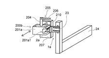
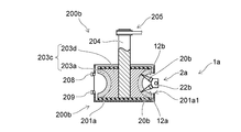
- the cleaning device 200b includes a storage unit 201a, a cleaning unit 203c, a rotating shaft 204, a power transmission unit 205, a supply unit 208, a recovery unit 209, and a movable unit 210.
- the storage unit 201a has a box shape and an upper surface is open.
- a hole 201a1 into which the nozzle head 2a is inserted is provided on the side surface of the storage unit 201a.
- the storage unit 201a has a function of protecting the cleaning unit 203c, a function of suppressing scattering of the solution, and a function of suppressing evaporation of the solution.
- the material of the storage unit 201 a can be the same as the material of the storage unit 201.
- the cleaning unit 203c is provided inside the storage unit 201a.
- the cleaning part 203c has a plurality of fibers 203a and a base part 203d. One end of the plurality of fibers 203a is held by the base 203d.
- the outer diameter size, length, material, and the like of the fiber 203a can be the same as those described above.
- the base 203d has a drum shape.
- the material of the base 203d can be the same as the material of the base 203b described above.
- the base 203d is connected to a motor (not shown) via the rotating shaft 204 and the power transmission unit 205.
- the power transmission unit 205 illustrated in FIGS. 4 and 5 is a belt and a pulley. In the present embodiment, rotating shaft 204, power transmission unit 205, a motor (not shown), and the like serve as a rotating unit that rotates cleaning unit 203c.
- the storage portion 201 a is provided on the support portion 207 via a bracket 206.
- a movable portion 210 is connected to the support portion 207 so that the cleaning device 200b can be moved in the direction in which the plurality of nozzles 20b are arranged.
- the movable part 210 may be connected to the main body part 24 and the nozzle head 2a may be moved. That is, the movable part 210 changes the relative position of the nozzle 20b and the cleaning part 203c.
- the movable unit 210 may include a servo motor and a ball screw.
- recovery part 209 are provided in the side surface of the side opposite to the side in which the hole 201a1 is provided of the accommodating part 201a.
- the supply unit 208 can be provided on the upper surface side of the storage unit 201a.
- a solution supply device (not shown) is connected to the supply unit 208.
- the solution supply device includes, for example, a tank for storing the solution, a pump for feeding the solution, an adjustment valve for adjusting the discharge amount of the solution, a switching valve for switching start and stop of discharge of the solution, and the like. be able to.
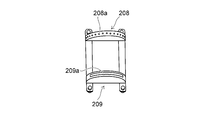
- the supply unit 208 is provided with a plurality of discharge ports 208a. The solution supplied to the inside of the supply unit 208 is discharged from the plurality of discharge ports 208a toward the cleaning unit 203c (a plurality of fibers 203a).
- the collection unit 209 can be provided on the bottom side of the storage unit 201a.
- the collection unit 209 collects the used solution.
- a solution recovery device (not shown) is connected to the recovery unit 209.
- the solution recovery apparatus includes, for example, a blower that sucks the solution and air, a switching valve that switches between starting and stopping suction, a separator that separates the solution and air, a tank that stores the separated solution, and the like. can do.
- the collection unit 209 is provided with a slit 209a. The used solution is sucked together with the air from the slit 209a and discharged to the outside of the storage unit 201a.
- control unit 6 moves the cleaning device 200b or the nozzle head 2a by the movable unit 210, rotates the base 203d by a motor (not shown), discharges the solution from the supply unit 208 by a pump (not shown), and uses a blower (not shown). It is possible to control the collection of the used solution via the collection unit 209.
- a base 203d provided with a plurality of fibers 203a is rotated via a rotating shaft 204 and a power transmission unit 205 by a motor (not shown).
- the rotation speed can be, for example, about 40 rpm to 50 rpm.
- the solution is discharged from the plurality of discharge ports 208a toward the cleaning unit 203c (a plurality of fibers 203a). Further, the used solution is sucked together with air from the slit 209a.
- the cleaning device 200b is moved in the direction in which the plurality of nozzles 20b are arranged by the movable portion 210, and the plurality of nozzles 20b are inserted into the plurality of fibers 203a.
- the relative moving speed of the cleaning device 200b can be set to about 10 cm / second, for example.
- the raw material liquid droplets and the polymer substance adhering to the tip of the nozzle 20 are scraped off by the rotating plurality of fibers 203a.
- the droplets of the raw material liquid and the polymer substance are dissolved by the solution. Therefore, it is easy to remove the raw material liquid droplets and the polymer substance.
- the rotation direction of the base 203d can be changed. If the rotation direction of the base 203d is changed, the fibers 203a can be easily brought into contact with all the side surfaces of the nozzle 20, so that the cleaning property can be further improved.
- the used solution is discharged to the outside of the storage unit 201a through the slit 209a of the recovery unit 209 together with the removed liquid droplets of the raw material liquid, the polymer substance, and air.
- the cleaning device 200b is moved in the reverse direction by the movable portion 210, and the plurality of nozzles 20b are separated from the plurality of fibers 203a.
- the relative moving speed of the cleaning device 200b can be set to about 10 cm / second, for example.
- the completion of the cleaning of the nozzle 20b can be confirmed visually by an operator, for example, or can be confirmed using an image processing apparatus or the like.
- the electrospinning apparatus 1a is restarted.
- the direction in which the rotating shaft 204 extends intersects with the direction in which the plurality of nozzles 20b are arranged, but the direction in which the rotating shaft 204 extends and the direction in which the plurality of nozzles 20b are arranged are parallel.
- the cleaning part 202 using a polymeric porous body may be provided.
- notches 202a and grooves can be provided at positions corresponding to the plurality of nozzles 20b.
- Tapers can be provided at openings such as the cuts 202a and grooves.
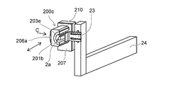
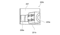
- the cleaning device 200c and the electrospinning device 1a are illustrated. As shown in FIGS. 7 and 8, the cleaning device 200c is provided with a storage portion 201b, a cleaning portion 203e, a bracket 206a, a support portion 207, and a movable portion 210.
- the storage unit 201b has a block shape.
- a cleaning unit 203e is provided on one side surface of the storage unit 201b.
- the material of the storage part 201b is not particularly limited as long as it is resistant to the solution and has a certain degree of rigidity.
- the storage unit 201b can be formed using, for example, a metal such as stainless steel or a resin such as nylon or polyimide.
- the cleaning unit 203e may be one using a polymer porous body or one using a plurality of fibers.
- the solution is supplied to the cleaning unit 203e by an operator or a supply device (not shown).
- the storage part 201b is provided on the support part 207 via a bracket 206a.
- a movable portion 210 is connected to the support portion 207 so that the cleaning device 200c can be moved in the direction in which the plurality of nozzles 20b are arranged.
- the movable part 210 may be connected to the main body part 24 and the nozzle head 2a may be moved.
- the storage portion 201b is attached to the bracket 206a using a fastening member such as a thumbscrew. Therefore, the cleaning device 200c can be easily attached and detached.
- the solution is supplied to the cleaning unit 203e by an operator or a supply device (not shown).
- the cleaning device 200c is moved in the direction in which the plurality of nozzles 20b are arranged by the movable portion 210, and the plurality of nozzles 20b are inserted into the plurality of fibers or the polymer porous body.
- the relative moving speed of the cleaning device 200c can be set to about 10 cm / second, for example.
- the raw material liquid droplets and the polymer substance adhering to the tip of the nozzle 20b are scraped off by the plurality of fibers or the polymer porous body.
- the droplets of the raw material liquid and the polymer substance are dissolved by the solution. Therefore, it is easy to remove the raw material liquid droplets and the polymer substance.
- the cleaning device 200c can be repeatedly reciprocated.
- the cleaning device 200c is moved in the reverse direction by the movable portion 210, and the plurality of nozzles 20b are separated from the plurality of fibers or the polymer porous body.
- the relative moving speed of the cleaning device 200c can be set to about 10 cm / second, for example.
- the completion of the cleaning of the nozzle 20b can be confirmed visually by an operator, for example, or can be confirmed using an image processing apparatus or the like. After the cleaning of the nozzle 20b is completed, the electrospinning apparatus 1a is restarted.
- FIGS. 9 and 10 a cleaning device 200d according to another embodiment is illustrated.
- the cleaning device 200d is illustrated in FIGS. 9 and 10.
- a plurality of nozzle heads 2a and the like are omitted.
- a plurality of nozzle heads 2a are provided on the mounting portion 24a1 of the main body portion 24a.
- the attachment portion 24a1 has a plate shape.
- a plurality of nozzle heads 2a are arranged side by side on one surface 24a1a of the mounting portion 24a1.
- a plurality of nozzle heads 2a are also provided side by side on the surface 24a1b of the mounting portion 24a1 facing the surface 24a1a.
- the cleaning device 200d is provided with a storage portion 201b, a cleaning portion 203e, a bracket 206b, a main body portion 207a, a leg portion 207b, and a handle 207c.
- One set of storage portion 201b and cleaning portion 203e is provided for one nozzle head 2a.
- the plurality of storage portions 201b are provided at positions corresponding to the plurality of nozzle heads 2a.
- the plurality of storage portions 201b are provided on the support portion 207a via the bracket 206b.
- the support portion 207a has a plate shape, and a leg portion 207b is provided at one end thereof.
- a handle 207c is provided on the side of the support portion 207a opposite to the side on which the plurality of storage portions 201b are provided.
- the solution is supplied to the cleaning unit 203e by an operator or a supply device (not shown).
- the solution is supplied to the cleaning unit 203c by an operator or a supply device (not shown).
- the operator holds the handle 207c, holds the cleaning device 200d, moves the cleaning device 200d in the direction in which the plurality of nozzles 20b are arranged, and puts the plurality of nozzles 20b into the plurality of fibers or the polymer porous body. insert.
- the moving speed of the cleaning device 200d can be set to about 10 cm / second, for example.
- the raw material liquid droplets and the polymer substance adhering to the tip of the nozzle 20b are scraped off by the plurality of fibers or the polymer porous body.
- the droplets of the raw material liquid and the polymer substance are dissolved by the solution. Therefore, it is easy to remove the raw material liquid droplets and the polymer substance. Further, the cleaning device 200d can be reciprocated repeatedly.
- the operator moves the cleaning device 200d in the opposite direction to separate the plurality of nozzles 20b from the plurality of fibers or the polymer porous body.
- the moving speed of the cleaning device 200d can be set to about 10 cm / second, for example.
- the completion of the cleaning of the nozzle 20b can be confirmed visually by an operator, for example, or can be confirmed using an image processing apparatus or the like.
- the electrospinning apparatus 1a is restarted.
Landscapes
- Engineering & Computer Science (AREA)
- Mechanical Engineering (AREA)
- Textile Engineering (AREA)
- Spinning Methods And Devices For Manufacturing Artificial Fibers (AREA)
Abstract
実施形態に係る清掃装置は、電界紡糸装置のノズルヘッドに設けられたノズルを清掃する清掃装置である。清掃装置は、箱状を呈し、一方の面が開口した収納部と、前記収納部の内部に設けられ、柔軟性を有し、溶液を保持可能な清掃部と、を備えている。
Description
本発明の実施形態は、清掃装置および電界紡糸装置に関する。
エレクトロスピニング法(電界紡糸法、電荷誘導紡糸法などとも称される)により、微細なファイバを部材の表面に堆積させる電界紡糸装置がある。電界紡糸装置には、原料液を排出するノズルが設けられている。
ここで、電界紡糸装置を停止させた際には、ノズルヘッドへの原料液の供給と、ノズルヘッドへの電圧の印加が停止されるので、ノズルからの原料液の排出が停止される。ところが、ノズルヘッドに接続された送液用の配管の内部やノズルヘッドの内部には残圧がある。そのため、電界紡糸装置を停止させたとしても、ノズルから原料液が漏れ出す場合がある。ノズルから原料液が漏れ出すと、ノズルの先端に原料液の液滴が付着したり、原料液が乾燥してノズルの先端に高分子物質が付着したりするおそれがある。乾燥することで粘度が高くなった原料液の液滴や高分子物質がノズルの先端に付着すると、ファイバの形成に悪影響を及ぼしたり、ノズル詰まりが生じたりするおそれがある。
ここで、電界紡糸装置を停止させた際には、ノズルヘッドへの原料液の供給と、ノズルヘッドへの電圧の印加が停止されるので、ノズルからの原料液の排出が停止される。ところが、ノズルヘッドに接続された送液用の配管の内部やノズルヘッドの内部には残圧がある。そのため、電界紡糸装置を停止させたとしても、ノズルから原料液が漏れ出す場合がある。ノズルから原料液が漏れ出すと、ノズルの先端に原料液の液滴が付着したり、原料液が乾燥してノズルの先端に高分子物質が付着したりするおそれがある。乾燥することで粘度が高くなった原料液の液滴や高分子物質がノズルの先端に付着すると、ファイバの形成に悪影響を及ぼしたり、ノズル詰まりが生じたりするおそれがある。
そのため、必要に応じてノズルの先端を清掃するようにしている。しかしながら、近年においては、生産性を向上させるためにノズルの数が増える傾向にあるので、効率の良いノズルの清掃を行うことが困難となっている。
そこで、クリーニング性を向上させることができる技術の開発が望まれていた。
そこで、クリーニング性を向上させることができる技術の開発が望まれていた。
本発明が解決しようとする課題は、クリーニング性を向上させることができる清掃装置および電界紡糸装置を提供することである。
実施形態に係る清掃装置は、電界紡糸装置のノズルヘッドに設けられたノズルを清掃する清掃装置である。清掃装置は、箱状を呈し、一方の面が開口した収納部と、前記収納部の内部に設けられ、柔軟性を有し、溶液を保持可能な清掃部と、を備えている。
以下、図面を参照しつつ、実施の形態について例示をする。なお、各図面中、同様の構成要素には同一の符号を付して詳細な説明は適宜省略する。
以下においては一例として、いわゆるニードル型ノズルヘッドを備えた電界紡糸装置を例示する。
ただし、ノズルヘッドはニードル型ノズルヘッドに限定されるわけではない。
以下においては一例として、いわゆるニードル型ノズルヘッドを備えた電界紡糸装置を例示する。
ただし、ノズルヘッドはニードル型ノズルヘッドに限定されるわけではない。
例えば、ノズルヘッドは、いわゆるブレード型ノズルヘッドなどであってもよい。ブレード型ノズルヘッドとすれば機械的強度を高めることができるので、清掃などの際にノズルが破損するのを抑制することができる。また、ノズルの清掃が容易となる。なお、ブレード型ノズルヘッドの形態には特に限定がなく、例えば、直方体状であったり、円弧状であったりしてもよい。
図1に示すように、本実施の形態に係る電界紡糸装置1には、ノズルヘッド2、原料液供給部3、電源4、収集部5、および制御部6が設けられている。
ノズルヘッド2は、ノズル20、接続部21、および本体部22を有する。
ノズル20は、1つ以上設けることができる。生産性を向上させるためには、複数のノズル20を設けることが好ましい。複数のノズル20を設ける場合には、複数のノズル20は、所定の間隔を空けて並べて設けることができる。なお、ノズル20の数や配設形態は例示をしたものに限定されるわけではなく、収集部5の大きさなどに応じて適宜変更することができる。例えば、複数のノズル20は、一列に並べて設けることもできるし、円周上あるいは同心円上に並べて設けることもできるし、マトリクス状に並べて設けることもできる。
ノズル20は、1つ以上設けることができる。生産性を向上させるためには、複数のノズル20を設けることが好ましい。複数のノズル20を設ける場合には、複数のノズル20は、所定の間隔を空けて並べて設けることができる。なお、ノズル20の数や配設形態は例示をしたものに限定されるわけではなく、収集部5の大きさなどに応じて適宜変更することができる。例えば、複数のノズル20は、一列に並べて設けることもできるし、円周上あるいは同心円上に並べて設けることもできるし、マトリクス状に並べて設けることもできる。
ノズル20は、針状を呈している。針状のノズル20とすればノズル20の排出口20aの近傍において電界集中が生じ易くなるので、ノズル20と収集部5の間に形成される電界の強度が高くなる。ノズル20の内部には、原料液を排出するための孔が設けられている。原料液を排出するための孔は、ノズル20の接続部21側の端部と、ノズル20の原料液が排出される側の端部(先端)との間を貫通している。ノズル20の内部に設けられた孔の、原料液が排出される側の開口が排出口20aとなる。ノズル20が延びる方向と直交する方向における外径寸法(以下、単に、ノズル20の外径寸法と称する)は、例えば、1mm程度とすることができる。排出口20aの、ノズル20が延びる方向と直交する方向における断面寸法(以下、単に、排出口20aの断面寸法と称する)には特に限定はない。排出口20aの断面寸法は、形成したいファイバ100の、ファイバ100が延びる方向と直交する方向における断面寸法に応じて適宜変更することができる。排出口20aの断面寸法は、例えば、200μm以上とすることができる。ノズル20は、例えば、ステンレスなどから形成することができる。
接続部21は、ノズル20と本体部22の間に設けられている。接続部21は、必ずしも必要ではなく、ノズル20が本体部22に直接設けられるようにしてもよい。接続部21の内部には、原料液を本体部22からノズル20に供給するための孔が設けられている。接続部21の内部に設けられた孔は、ノズル20の内部に設けられた孔、および、本体部22の内部に設けられた空間と繋がっている。接続部21は、例えば、ステンレスなどから形成することができる。
本体部22は、板状を呈している。本体部22の内部には、原料液が収納される空間が設けられている。本体部22の一方の端部には、接続部21を介してノズル20が複数設けられている。本体部22には、供給口22aが設けられている。原料液供給部3から供給された原料液は、供給口22aを介して本体部22の内部に導入される。
原料液供給部3は、収納部31、供給部32、原料液制御部33、および配管34を有する。
収納部31は、原料液を収納する。収納部31は、原料液に対する耐性を有する材料から形成されている。収納部31は、例えば、ステンレスなどから形成することができる。
収納部31は、原料液を収納する。収納部31は、原料液に対する耐性を有する材料から形成されている。収納部31は、例えば、ステンレスなどから形成することができる。
原料液は、高分子物質を溶媒に溶解したものである。
高分子物質には特に限定がなく、形成したいファイバ100の材質に応じて適宜変更することができる。高分子物質は、例えば、ポリプロピレン、ポリエチレン、ポリスチレン、ポリエチレンテレフタレート、ポリ塩化ビニル、ポリカーボネート、ナイロン、アラミドなどとすることができる。
高分子物質には特に限定がなく、形成したいファイバ100の材質に応じて適宜変更することができる。高分子物質は、例えば、ポリプロピレン、ポリエチレン、ポリスチレン、ポリエチレンテレフタレート、ポリ塩化ビニル、ポリカーボネート、ナイロン、アラミドなどとすることができる。
溶媒は、高分子物質を溶解することができるものであればよい。溶媒は、溶解させる高分子物質に応じて適宜変更することができる。溶媒は、例えば、メタノール、エタノール、イソプロピルアルコール、アセトン、ベンゼン、トルエンなどとすることができる。
なお、高分子物質および溶媒は、例示をしたものに限定されるわけではない。
なお、高分子物質および溶媒は、例示をしたものに限定されるわけではない。
原料液は、表面張力により排出口20aの近傍に留まる様にされる。原料液の粘度は、排出口20aの寸法などに応じて適宜変更することができる。原料液の粘度は、実験やシミュレーションを行うことで求めることができる。また、原料液の粘度は、溶媒と高分子物質の混合割合により制御することができる。
供給部32は、収納部31に収納されている原料液を本体部22に供給する。供給部32は、例えば、原料液に対する耐性を有するポンプなどとすることができる。また、供給部32は、例えば、収納部31にガスを供給し、収納部31に収納されている原料液を圧送するものとすることもできる。
原料液制御部33は、本体部22に供給される原料液の流量、圧力などを制御して、新しい原料液が本体部22の内部に供給された際に、本体部22の内部にある原料液が排出口20aから押し出されないようにする。原料液制御部33は、例えば、流量制御弁や圧力制御弁などとすることができる。なお、原料液制御部33に対する制御量は、排出口20aの寸法や原料液の粘度などにより適宜変更することができる。原料液制御部33に対する制御量は、実験やシミュレーションを行うことで求めることができる。また、原料液制御部33は、原料液の供給の開始と、供給の停止を切り替えることができる。
配管34は、収納部31と供給部32との間、供給部32と原料液制御部33との間、原料液制御部33と本体部22との間に設けられている。配管34は、原料液の流路となる。配管34は、原料液に対する耐性を有する材料から形成されている。
電源4は、本体部22および接続部21を介してノズル20に電圧を印加する。なお、複数のノズル20と電気的に接続された図示しない端子を設けるようにしてもよい。この場合、電源4は、図示しない端子を介してノズル20に電圧を印加する。すなわち、電源4から複数のノズル20に電圧が印加できるようになっていればよい。
ノズル20に印加する電圧の極性は、プラスとすることもできるし、マイナスとすることもできる。なお、図1に例示をした電源4は、ノズル20にプラスの電圧を印加する。
ノズル20に印加する電圧は、原料液に含まれる高分子物質の種類、ノズル20と収集部5との間の距離などに応じて適宜変更することができる。例えば、電源4は、ノズル20と収集部5との間の電位差が10kV以上となるように、ノズル20に電圧を印加する。電源4は、例えば、直流高圧電源とすることができる。電源4は、例えば、10kV以上100kV以下の直流電圧を出力する。
ノズル20に印加する電圧は、原料液に含まれる高分子物質の種類、ノズル20と収集部5との間の距離などに応じて適宜変更することができる。例えば、電源4は、ノズル20と収集部5との間の電位差が10kV以上となるように、ノズル20に電圧を印加する。電源4は、例えば、直流高圧電源とすることができる。電源4は、例えば、10kV以上100kV以下の直流電圧を出力する。
収集部5は、ノズル20の原料液が排出される側に設けられている。収集部5は、例えば、接地することができる。収集部5には、ノズル20に印加する電圧と逆極性の電圧を印加するようにしてもよい。収集部5は、導電性材料から形成することができる。収集部5の材料は、導電性と原料液に対する耐性を有するものとすることが好ましい。収集部5の材料は、例えば、ステンレスなどとすることができる。
収集部5は、例えば、板状やシート状を呈するものとすることができる。シート状を呈する収集部5の場合には、ロール等に巻きつけられた収集部5にファイバ100を堆積させることができる。
また、収集部5は、移動するものであってもよい。例えば、一対の回転ドラムと、回転ドラムを回転させる駆動部を設け、ベルトコンベアのように一対の回転ドラムの間を収集部5が移動するようにしてもよい。この様にすれば、ファイバ100を堆積させる領域を移動させることができるので、連続的な堆積作業が可能となる。そのため、ファイバ100を含む堆積体110の生産効率を向上させることができる。
また、収集部5は、製品の基部であってもよい。
一般的には、収集部5の上に形成された堆積体110は、収集部5から取り外される。この場合、堆積体110は、例えば、不織布やフィルタなどに用いられる。しかしながら、製品の基部の表面に堆積体110を直接形成する場合がある。この様な場合には、導電性を有する基部を接地したり、導電性を有する基部にノズル20に印加する電圧と逆極性の電圧を印加したりすればよい。
一般的には、収集部5の上に形成された堆積体110は、収集部5から取り外される。この場合、堆積体110は、例えば、不織布やフィルタなどに用いられる。しかしながら、製品の基部の表面に堆積体110を直接形成する場合がある。この様な場合には、導電性を有する基部を接地したり、導電性を有する基部にノズル20に印加する電圧と逆極性の電圧を印加したりすればよい。
制御部6は、供給部32、原料液制御部33、および電源4の動作を制御する。制御部6は、例えば、CPU(Central Processing Unit)やメモリなどを備えたコンピュータとすることができる。
次に、電界紡糸装置1の作用について説明する。
原料液は、表面張力によりノズル20の排出口20aの近傍に留まっている。
電源4は、ノズル20に電圧を印加する。すると、排出口20aの近傍にある原料液が所定の極性に帯電する。図1に例示をしたものの場合には、排出口20aの近傍にある原料液がプラスに帯電する。
原料液は、表面張力によりノズル20の排出口20aの近傍に留まっている。
電源4は、ノズル20に電圧を印加する。すると、排出口20aの近傍にある原料液が所定の極性に帯電する。図1に例示をしたものの場合には、排出口20aの近傍にある原料液がプラスに帯電する。
収集部5は、接地されているので、ノズル20と収集部5の間に電界が形成される。そして、電気力線に沿って作用する静電力が表面張力より大きくなると、排出口20aの近傍にある原料液が静電力により収集部5に向けて引き出される。引き出された原料液は、引き伸ばされ、原料液に含まれる溶媒が揮発することでファイバ100が形成される。形成されたファイバ100が収集部5の上に堆積することで、堆積体110が形成される。
ここで、生産中に電界紡糸装置1を異常停止させたり、生産の終了により電界紡糸装置1を停止させたりする場合には、制御部6は、ノズルヘッド2への原料液の供給と、ノズルヘッド2への電圧の印加を停止する。そのため、ノズル20の排出口20aの近傍にある原料液が引き出されるのが停止される。ところが、原料液制御部33と本体部22との間の配管34の内部にある原料液や、本体部22の内部にある原料液には供給圧力が印加されたままの状態となっている。すなわち、本体部22に接続された配管34の内部や本体部22の内部には残圧がある。そのため、原料液制御部33により原料液の供給を停止させたとしても、ノズル20の排出口20aの近傍にある原料液がノズル20から漏れ出す場合がある。ノズル20から原料液が漏れ出すと、ノズル20の先端に原料液の液滴が付着したり、原料液が乾燥してノズル20の先端に高分子物質が付着したりするおそれがある。乾燥することで粘度が高くなった原料液の液滴や高分子物質がノズル20の先端に付着すると、排出口20aからの原料液の排出が阻害され、適切なファイバ100が形成されなくなるおそれがある。また、粘度が高くなった原料液の液滴や高分子物質により排出口20aが塞がれて、ノズル20詰まりが生じるおそれもある。
そのため、必要に応じて、あるいは定期的に、ノズル20の先端を清掃している。一般的には、ノズル20の先端に付着した原料液が固化する前に布などで拭き取るようにしている。
ところが、原料液に含まれる溶媒は揮発性の高い液体であるため、原料液が固化する前に拭き取るようにする場合には清掃を頻繁に行う必要がある。そのため、清掃のために電界紡糸装置1を停止させる時間が長くなり生産性が低下する要因となる。
ところが、原料液に含まれる溶媒は揮発性の高い液体であるため、原料液が固化する前に拭き取るようにする場合には清掃を頻繁に行う必要がある。そのため、清掃のために電界紡糸装置1を停止させる時間が長くなり生産性が低下する要因となる。
また、針状を呈するノズル20の場合にはノズル20の強度が低いため、付着した原料液を一度に拭き取るようにすると、ノズル20が曲がったり、ノズル20が破損したりするおそれがある。そのため、複数のノズル20を一本ずつ清掃する必要がある。近年においては、生産性を向上させるためにノズル20の数が増える傾向にあるので、清掃に要する時間がさらに長くなる。
そこで、ノズル20の清掃が必要となった場合には、本実施の形態に係る清掃装置200を用いてノズル20の清掃を行う。
そこで、ノズル20の清掃が必要となった場合には、本実施の形態に係る清掃装置200を用いてノズル20の清掃を行う。
図2(a)、(b)に示すように、清掃装置200には、収納部201と清掃部202が設けられている。
収納部201は、箱状を呈し、一方の面が開口している。清掃部202は、収納部201の内部に設けられている。そのため、清掃部202は、収納部201の一方の面側に露出している。清掃部202の露出面(収納部201の底側とは反対側の面)は、収納部201の開口の位置に設けることもできるし、収納部201の開口の位置よりは僅かに外側の位置に設けることもできるし、収納部201の開口の位置よりは僅かに内側の位置に設けることもできる。
また、収納部201の内部には溶液が供給される。供給された溶液は、清掃部202に保持される。溶液は、原料液に含まれる高分子物質を溶解することができるものであれば特に限定はない。溶液は、例えば、前述した原料液に含まれる溶媒と同じ液体とすることができる。
収納部201は、清掃部202を保持する機能、清掃部202を保護する機能、溶液を保持する機能、および、溶液の蒸発を抑制する機能を有する。
例えば、収納部201の内部に清掃部202を設けることで、収納部201が清掃部202を保持し、収納部201が清掃部202を外力などから保護する。また、収納部201は箱状を呈しているので、収納部201の内部に供給された溶液を保持することができる。また、収納部201の開口は一方の面だけであるので、清掃部202に保持された溶液が蒸発するのを抑制することができる。
例えば、収納部201の内部に清掃部202を設けることで、収納部201が清掃部202を保持し、収納部201が清掃部202を外力などから保護する。また、収納部201は箱状を呈しているので、収納部201の内部に供給された溶液を保持することができる。また、収納部201の開口は一方の面だけであるので、清掃部202に保持された溶液が蒸発するのを抑制することができる。
収納部201の材料は、溶液に対する耐性を有し、ある程度の剛性を有するものであれば特に限定はない。収納部201は、例えば、ステンレスなどの金属や、ナイロンやポリイミドなどの樹脂などを用いて形成することができる。
清掃部202は、柔軟性を有し、且つ、溶液を保持する。清掃部202は、例えば、高分子多孔質体を用いて形成することができる。高分子多孔質体としては、例えば、樹脂発泡体(プラスチックフォーム)などの高分子発泡体を例示することができる。この場合、溶液を保持することを考慮すると、清掃部202は、連続気泡構造体とすることが好ましい。清掃部202は、例えば、メラミンフォーム(発泡メラミン)やウレタンフォーム(発泡ポリウレタン)などを用いたスポンジから形成することができる。なお、溶液は、清掃部202の内部にある孔や隙間の内部に保持される。
清掃部202の保持には、接着剤などの接合材を用いることもできるし、清掃部202が有する弾性力を利用することもできる。
後述する様に清掃部202にはノズル20が挿入されるので、少しずつではあるが清掃部202は損傷する。また、清掃部202の内部には、ノズル20の先端に付着していた原料液や高分子物質が残ることになる。そのため、清掃部202は、消耗品とすることができる。この場合、清掃部202が有する弾性力を利用して収納部201の内部に清掃部202を保持させれば、交換を容易とすることができる。
後述する様に清掃部202にはノズル20が挿入されるので、少しずつではあるが清掃部202は損傷する。また、清掃部202の内部には、ノズル20の先端に付着していた原料液や高分子物質が残ることになる。そのため、清掃部202は、消耗品とすることができる。この場合、清掃部202が有する弾性力を利用して収納部201の内部に清掃部202を保持させれば、交換を容易とすることができる。
また、清掃部202は、ノズル20が挿入される切り込み202aを有していてもよい。切り込み202aの代わりに、ノズル20よりも細い孔を設けることもできる。切り込み202aや孔を設ければ、清掃部202の損傷を抑制することができるので、清掃部202の交換頻度を低減させることができる。また、切り込み202aやノズル20よりも細い孔で有れば、清掃部202をノズル20に密着させることができるので、ノズル20の先端に付着していた原料液や高分子物質を拭き取ったり溶解させたりすることができる。ノズル20を孔に挿入する際の位置合わせ精度を考慮すると、切り込み202aを設けることが好ましい。また、切り込み202aとすれば、ブレード型ノズルヘッドの清掃を容易とすることができる。なお、ブレード型ノズルヘッドの清掃を行う場合には、切り込み202aに代えて溝を設けることができる。この場合、溝の幅は、ブレード型ノズルヘッドの厚みより短くすればよい。なお、ブレード型ノズルヘッドには既知の技術を適用することができるので、ブレード型ノズルヘッドの詳細な説明は省略する。
ノズル20の清掃を行う際には、まず、ノズル20の先端が清掃部202の開口側から清掃部202の内部に挿入される。この際、清掃部202の露出面と、ノズル20が延びる方向との間の角度がほぼ90°となるようにすることが好ましい。この場合、清掃装置200をノズル20の先端に向けて移動させることもできるし、ノズル20を清掃装置200に向けて移動させることもできる。ノズル20の先端が清掃部202の内部に挿入されることで、清掃部202がノズル20の先端に付着している原料液の液滴や高分子物質と密着し、且つ、清掃部202に保持されている溶液が原料液の液滴や高分子物質と接触する。原料液の液滴や高分子物質は、溶液により溶解される。
次に、ノズル20の先端が清掃部202の内部から引き抜かれる。すると、清掃部202が原料液の液滴や高分子物質を拭き取る。この際、溶液により、原料液の液滴や高分子物質が溶解されているので、原料液の液滴や高分子物質の除去が容易となる。
本実施の形態に係る清掃装置200とすれば、クリーニング性を向上させることができる。
本実施の形態に係る清掃装置200とすれば、クリーニング性を向上させることができる。
また、高分子物質の溶解には所定の時間を要する場合がある。この様な場合には、所定の時間の経過後にノズル20の先端を清掃部202の内部から引き抜くようにすればよい。
原料液の液滴や高分子物質の除去が不充分な場合には、ノズル20の先端の挿入と引き抜きを繰り返し行うことができる。なお、清掃装置200の相対移動速度(ノズル20の先端の挿入と引き抜きの速度)は、例えば、10cm/秒程度とすることができる。
原料液の液滴や高分子物質の除去が不充分な場合には、ノズル20の先端の挿入と引き抜きを繰り返し行うことができる。なお、清掃装置200の相対移動速度(ノズル20の先端の挿入と引き抜きの速度)は、例えば、10cm/秒程度とすることができる。
ノズル20の清掃の完了は、例えば、作業者が目視確認することもできるし、画像処理装置などを用いて確認することもできる。
ノズル20の清掃の完了後は、電界紡糸装置1が再運転される。
生産の中断や終了などにより電界紡糸装置1が再運転されるまでの時間が長くなる場合には、清掃後のノズル20の先端を清掃部202の内部に挿入することもできる。この場合、ノズル20と清掃部202との間の密着力により清掃装置200を保持することもできるし、磁石やネジなどにより電界紡糸装置1の要素に清掃装置200を保持させることもできる。清掃部202の内部には溶液が保持されており、溶液は原料液に含まれている高分子物質を溶解するので、ノズル20の内部にある原料液が固化するのを抑制することができる。そのため、電界紡糸装置1が再運転された際にノズル20詰まりが生じるのを抑制することができる。
ノズル20の清掃の完了後は、電界紡糸装置1が再運転される。
生産の中断や終了などにより電界紡糸装置1が再運転されるまでの時間が長くなる場合には、清掃後のノズル20の先端を清掃部202の内部に挿入することもできる。この場合、ノズル20と清掃部202との間の密着力により清掃装置200を保持することもできるし、磁石やネジなどにより電界紡糸装置1の要素に清掃装置200を保持させることもできる。清掃部202の内部には溶液が保持されており、溶液は原料液に含まれている高分子物質を溶解するので、ノズル20の内部にある原料液が固化するのを抑制することができる。そのため、電界紡糸装置1が再運転された際にノズル20詰まりが生じるのを抑制することができる。
次に、他の実施形態に係る清掃装置200aについて例示する。
図3(a)、(b)に示すように、清掃装置200aには収納部201と清掃部203が設けられている。
収納部201は、清掃部203を保持する機能、清掃部203を保護する機能、溶液を保持する機能、および、溶液の蒸発を抑制する機能を有する。収納部201は、前述したものと同様とすることができる。
図3(a)、(b)に示すように、清掃装置200aには収納部201と清掃部203が設けられている。
収納部201は、清掃部203を保持する機能、清掃部203を保護する機能、溶液を保持する機能、および、溶液の蒸発を抑制する機能を有する。収納部201は、前述したものと同様とすることができる。
清掃部203は、収納部201の内部に設けられている。清掃部203は、複数の繊維203aと、基部203bとを有する。
複数の繊維203aの一方の端部は、基部203bに保持されている。複数の繊維203aの他方の端部は、収納部201の開口の位置に設けることもできるし、収納部201の開口の位置よりは僅かに外側の位置に設けることもできるし、収納部201の開口の位置よりは僅かに内側の位置に設けることもできる。そのため、収納部201の内部の深さ寸法は、後述する繊維203aの長さに応じて適宜決定することができる。
複数の繊維203aの一方の端部は、基部203bに保持されている。複数の繊維203aの他方の端部は、収納部201の開口の位置に設けることもできるし、収納部201の開口の位置よりは僅かに外側の位置に設けることもできるし、収納部201の開口の位置よりは僅かに内側の位置に設けることもできる。そのため、収納部201の内部の深さ寸法は、後述する繊維203aの長さに応じて適宜決定することができる。
複数の繊維203a同士の間の距離(隙間)は、ノズル20の外径寸法よりは短くすることが好ましい。この様にすれば、複数の繊維203aをノズル20に確実に接触させることができる。
また、収納部201の内部には溶液が供給される。溶液は、前述したものと同様とすることができる。供給された溶液は、複数の繊維203a同士の間に保持される。溶液の保持力は、複数の繊維203a同士の間の距離、溶液の表面張力、溶液の粘度などの影響を受け得る。そのため、複数の繊維203a同士の間の距離は、ノズル20の外径寸法、溶液の表面張力、溶液の粘度などを考慮してシミュレーションや実験などを行うことで適宜決定することができる。
繊維203aの、繊維203aが延びる方向と直交する方向における外径寸法(以下、単に、繊維203aの外径寸法と称する)が長すぎたり、繊維203aの長さが短すぎたりすると、繊維203aの柔軟性が低くなりすぎてノズル20が破損するおそれがある。一方、繊維203aの外径寸法が短すぎたり、繊維203aの長さが長すぎたりすると、繊維203aの柔軟性が高くなりすぎてクリーニング効果が低下するおそれがある。
本発明者の得た知見によれば、繊維203aの外径寸法は0.075mm以上、0.2mm以下とすることが好ましい。繊維203aの長さは、20mm以上とすることが好ましい。
本発明者の得た知見によれば、繊維203aの外径寸法は0.075mm以上、0.2mm以下とすることが好ましい。繊維203aの長さは、20mm以上とすることが好ましい。
清掃部203の材料は、溶液に対する耐性を有し、ノズル20に傷などの損傷を与えないものであれば特に限定はない。清掃部203の材料は、例えば、ナイロンやポリイミドなどの樹脂とすることができる。
基部203bは、板状を呈し、収納部201の内部に保持されている。基部203bは、収納部201の底面に設けることができる。基部203bの保持には、接着剤などの接合材を用いることもできるし、ネジなどの締結部材を用いることもできる。基部203bの材料は、溶液に対する耐性を有するものであれば特に限定はない。基部203bの材料は、例えば、ナイロンやポリイミドなどの樹脂や、ステンレスなどの金属とすることができる。
清掃装置200aによるノズル20の清掃は、前述した清掃装置200によるノズル20の清掃と同様とすることができる。この場合、繊維203aがノズル20の先端に付着している原料液の液滴や高分子物質と接触し、繊維203aにより原料液の液滴や高分子物質が掻き落とされる。この際、原料液の液滴や高分子物質は、溶液により溶解されているので、原料液の液滴や高分子物質の除去が容易となる。
原料液の液滴や高分子物質の除去が不充分な場合には、清掃装置200aとノズル20との相対的な位置を繰り返し往復移動させればよい。例えば、複数のノズル20が並ぶ方向に清掃装置200aを繰り返し往復移動させるようにすればよい。清掃装置200aの相対移動速度は、例えば、10cm/秒程度とすることができる。
ノズル20の清掃の完了後、電界紡糸装置1が再運転されるまでの時間が長くなる場合には、清掃後のノズル20の先端を清掃部202の内部に挿入することができる。この場合、磁石やネジなどにより電界紡糸装置1の要素に清掃装置200aを保持させることができる。この様にすれば、前述した清掃装置200と同様に、電界紡糸装置1が再運転された際にノズル20詰まりが生じるのを抑制することができる。
本実施の形態に係る清掃装置200aとすれば、ブレード型ノズルヘッドの清掃にも用いることができる。また、清掃装置200aの寿命を長くすることができる。
次に、他の実施形態に係る清掃装置200bおよび電界紡糸装置1aについて例示する。
図4に示すように、電界紡糸装置1aには、ノズルヘッド2a、ブラケット23、および本体部24が設けられている。また、図示は省略したが、原料液供給部3、電源4、収集部5、および制御部6が設けられている。
図4に示すように、電界紡糸装置1aには、ノズルヘッド2a、ブラケット23、および本体部24が設けられている。また、図示は省略したが、原料液供給部3、電源4、収集部5、および制御部6が設けられている。
図4および図5に示すように、ノズルヘッド2aは、ノズル20bおよび本体部22bを有する。
ノズル20bは、複数設けられている。複数のノズル20bは、複数のノズル群に分けて設けられている。この場合、1つのノズル群には少なくとも1つのノズル20bが設けられている。なお、以下においては、一例として、1つのノズル群に複数のノズル20bが設けられる場合を説明する。
ノズル20bは、複数設けられている。複数のノズル20bは、複数のノズル群に分けて設けられている。この場合、1つのノズル群には少なくとも1つのノズル20bが設けられている。なお、以下においては、一例として、1つのノズル群に複数のノズル20bが設けられる場合を説明する。
1つのノズル群において、複数のノズル20bは、所定の方向に並べて設けられている。第1のノズル群12aに属する複数のノズル20bは、互いに平行となっている。第2のノズル群12bに属する複数のノズル20bは、互いに平行となっている。
本体部22bが延びる方向から見て、第2のノズル群12bに属する複数のノズル20bが延びる方向は、第1のノズル群12aに属する複数のノズル20bが延びる方向と交差している。
本体部22bが延びる方向から見て、第2のノズル群12bに属する複数のノズル20bが延びる方向は、第1のノズル群12aに属する複数のノズル20bが延びる方向と交差している。
また、本体部22bが延びる方向から見て、第2のノズル群12bに属する複数のノズル20bは、先端側(排出口側)になるに従い第1のノズル群12aに属する複数のノズル20bから離れる方向に延びている。
この様にすれば、本体部22bが延びる方向から見て、第1のノズル群12aに属する複数のノズル20bと、第2のノズル群12bに属する複数のノズル20bとを平行とした場合よりも、第1のノズル群12aに属する複数のノズル20bの排出口側の端面と、第2のノズル群12bに属する複数のノズル20bの排出口側の端面との間の距離を長くすることができる。そのため、第1のノズル群12aに属する複数のノズル20bの排出口側の端面と、第2のノズル群12bに属する複数のノズル20bの排出口側の端面との間で電界干渉が生じるのを抑制することができる。その結果、ファイバ100の形成を安定させることができる。
また、複数のノズル20bは円錐状を呈し、本体部22bに直接設けられている。円錐状のノズル20bとすれば、ノズル20bの機械的強度を高めることができる。そのため、清掃などの際にノズル20bが破損するのを抑制することができる。また、ノズル20bの清掃が容易となる。また、円錐状のノズル20bの先端を尖らせることができるので、針状のノズル20と同様にノズル20bと収集部5の間に形成される電界の強度を高くすることができる。
本体部22bは棒状を呈している。本体部22bの内部には、原料液が収納される空間が設けられている。本体部22bの構成や材料などは、前述した本体部22と同様とすることができる。
ノズルヘッド2aは、ブラケット23を介して本体部24に取り付けられている。
本体部22bは棒状を呈している。本体部22bの内部には、原料液が収納される空間が設けられている。本体部22bの構成や材料などは、前述した本体部22と同様とすることができる。
ノズルヘッド2aは、ブラケット23を介して本体部24に取り付けられている。
図4、図5、および図6に示すように、清掃装置200bには、収納部201a、清掃部203c、回転軸204、動力伝達部205、供給部208、回収部209、および可動部210が設けられている。
収納部201aは、箱状を呈し、上面が開口している。収納部201aの側面には、ノズルヘッド2aが挿入される孔201a1設けられている。収納部201aは、清掃部203cを保護する機能、溶液の飛散を抑制する機能、および、溶液の蒸発を抑制する機能を有する。収納部201aの材料は、収納部201の材料と同様とすることができる。
収納部201aは、箱状を呈し、上面が開口している。収納部201aの側面には、ノズルヘッド2aが挿入される孔201a1設けられている。収納部201aは、清掃部203cを保護する機能、溶液の飛散を抑制する機能、および、溶液の蒸発を抑制する機能を有する。収納部201aの材料は、収納部201の材料と同様とすることができる。
清掃部203cは、収納部201aの内部に設けられている。清掃部203cは、複数の繊維203aと、基部203dとを有する。
複数の繊維203aの一方の端部は、基部203dに保持されている。繊維203aの外径寸法、長さ、材料などは前述したものと同様とすることができる。
基部203dは、鼓状を呈している。基部203dの材料は、前述した基部203bの材料と同様とすることができる。基部203dは、回転軸204および動力伝達部205を介して図示しないモータと接続されている。図4および図5に例示をした動力伝達部205は、ベルトとプーリである。
本実施の形態においては、回転軸204、動力伝達部205、図示しないモータなどが、清掃部203cを回転させる回転部となる。
複数の繊維203aの一方の端部は、基部203dに保持されている。繊維203aの外径寸法、長さ、材料などは前述したものと同様とすることができる。
基部203dは、鼓状を呈している。基部203dの材料は、前述した基部203bの材料と同様とすることができる。基部203dは、回転軸204および動力伝達部205を介して図示しないモータと接続されている。図4および図5に例示をした動力伝達部205は、ベルトとプーリである。
本実施の形態においては、回転軸204、動力伝達部205、図示しないモータなどが、清掃部203cを回転させる回転部となる。
また、図4に示すように、収納部201aは、ブラケット206を介して支持部207に設けられている。支持部207には可動部210が接続され、清掃装置200bを複数のノズル20bが並ぶ方向に移動できる様になっている。なお、可動部210を本体部24に接続し、ノズルヘッド2aを移動させてもよい。すなわち、可動部210は、ノズル20bと、清掃部203cとの相対的な位置を変化させる。可動部210は、例えば、サーボモータとボールネジを備えたものとすることができる。
図5に示すように、供給部208および回収部209は、収納部201aの、孔201a1が設けられる側と対向する側の側面に設けられている。
供給部208は、収納部201aの上面側に設けることができる。供給部208には図示しない溶液供給装置が接続されている。溶液供給装置は、例えば、溶液を収納するタンク、溶液を送液するポンプ、溶液の吐出量を調整する調整弁、溶液の吐出の開始と吐出の停止を切り替える切替弁などを備えたものとすることができる。供給部208には複数の吐出口208aが設けられている。供給部208の内部に供給された溶液は、複数の吐出口208aから清掃部203c(複数の繊維203a)に向けて吐出される。
供給部208は、収納部201aの上面側に設けることができる。供給部208には図示しない溶液供給装置が接続されている。溶液供給装置は、例えば、溶液を収納するタンク、溶液を送液するポンプ、溶液の吐出量を調整する調整弁、溶液の吐出の開始と吐出の停止を切り替える切替弁などを備えたものとすることができる。供給部208には複数の吐出口208aが設けられている。供給部208の内部に供給された溶液は、複数の吐出口208aから清掃部203c(複数の繊維203a)に向けて吐出される。
回収部209は、収納部201aの底面側に設けることができる。回収部209は、使用済みの溶液を回収する。回収部209には図示しない溶液回収装置が接続されている。溶液回収装置は、例えば、溶液と空気を吸引するブロア、吸引の開始と吸引の停止とを切り替える切替弁、溶液と空気を分離するセパレータ、分離された溶液を収納するタンクなどを備えたものとすることができる。回収部209にはスリット209aが設けられている。使用済みの溶液は、スリット209aから空気とともに吸引され、収納部201aの外部に排出される。
この場合、前述した制御部6は、可動部210による清掃装置200bまたはノズルヘッド2aの移動、図示しないモータによる基部203dの回転、図示しないポンプによる供給部208からの溶液の吐出、図示しないブロアによる回収部209を介した使用済みの溶液の回収などを制御することができる。
次に、清掃装置200bの作用について説明する。
まず、図示しないモータにより、回転軸204および動力伝達部205を介して複数の繊維203aが設けられた基部203dを回転させる。回転数は、例えば、40rpm~50rpm程度とすることができる。
次に、複数の吐出口208aから清掃部203c(複数の繊維203a)に向けて溶液を吐出させる。また、スリット209aから空気とともに使用済みの溶液を吸引する。
まず、図示しないモータにより、回転軸204および動力伝達部205を介して複数の繊維203aが設けられた基部203dを回転させる。回転数は、例えば、40rpm~50rpm程度とすることができる。
次に、複数の吐出口208aから清掃部203c(複数の繊維203a)に向けて溶液を吐出させる。また、スリット209aから空気とともに使用済みの溶液を吸引する。
次に、可動部210により清掃装置200bを複数のノズル20bが並ぶ方向に移動させて、複数のノズル20bを複数の繊維203aの中に挿入する。清掃装置200bの相対移動速度は、例えば、10cm/秒程度とすることができる。
すると、回転する複数の繊維203aにより、ノズル20の先端に付着している原料液の液滴や高分子物質が掻き取られる。原料液の液滴や高分子物質は、溶液により溶解される。そのため、原料液の液滴や高分子物質の除去が容易となる。
すると、回転する複数の繊維203aにより、ノズル20の先端に付着している原料液の液滴や高分子物質が掻き取られる。原料液の液滴や高分子物質は、溶液により溶解される。そのため、原料液の液滴や高分子物質の除去が容易となる。
また、基部203dの回転方向を変化させることができる。基部203dの回転方向を変化させれば、ノズル20の全側面に繊維203aを接触させるのが容易となるので、クリーニング性をより向上させることができる。
使用済みの溶液は、除去された原料液の液滴や高分子物質、および空気とともに、回収部209のスリット209aを介して収納部201aの外部に排出される。
使用済みの溶液は、除去された原料液の液滴や高分子物質、および空気とともに、回収部209のスリット209aを介して収納部201aの外部に排出される。
次に、可動部210により清掃装置200bを逆方向に移動させて、複数のノズル20bを複数の繊維203aから離隔させる。清掃装置200bの相対移動速度は、例えば、10cm/秒程度とすることができる。
ノズル20bの清掃の完了は、例えば、作業者が目視確認することもできるし、画像処理装置などを用いて確認することもできる。
ノズル20bの清掃の完了後は、電界紡糸装置1aが再運転される。
ノズル20bの清掃の完了は、例えば、作業者が目視確認することもできるし、画像処理装置などを用いて確認することもできる。
ノズル20bの清掃の完了後は、電界紡糸装置1aが再運転される。
以上においては、回転軸204が延びる方向と、複数のノズル20bが並ぶ方向とが交差しているが、回転軸204が延びる方向と、複数のノズル20bが並ぶ方向とが平行となっていてもよい。
また、複数の繊維203aが設けられる場合を例示したが、高分子多孔質体を用いた清掃部202を設けてもよい。この場合、複数のノズル20bに対応する位置に、切り込み202aや溝などを設けることができる。切り込み202aや溝などの開口部分にはテーパ(入り勝手)を設けることができる。
また、複数の繊維203aが設けられる場合を例示したが、高分子多孔質体を用いた清掃部202を設けてもよい。この場合、複数のノズル20bに対応する位置に、切り込み202aや溝などを設けることができる。切り込み202aや溝などの開口部分にはテーパ(入り勝手)を設けることができる。
次に、他の実施形態に係る清掃装置200cおよび電界紡糸装置1aについて例示する。
図7および図8に示すように、清掃装置200cには、収納部201b、清掃部203e、ブラケット206a、支持部207、および可動部210が設けられている。
図7および図8に示すように、清掃装置200cには、収納部201b、清掃部203e、ブラケット206a、支持部207、および可動部210が設けられている。
収納部201bは、ブロック状を呈している。収納部201bの一方の側面には清掃部203eが設けられている。収納部201bの材料は、溶液に対する耐性を有し、ある程度の剛性を有するものであれば特に限定はない。収納部201bは、例えば、ステンレスなどの金属や、ナイロンやポリイミドなどの樹脂などを用いて形成することができる。
清掃部203eは、高分子多孔質体を用いたものであってもよいし、複数の繊維を用いたものであってもよい。
溶液は、作業者または図示しない供給装置により清掃部203eに供給される。
溶液は、作業者または図示しない供給装置により清掃部203eに供給される。
収納部201bは、ブラケット206aを介して支持部207に設けられている。支持部207には可動部210が接続され、清掃装置200cを複数のノズル20bが並ぶ方向に移動できる様になっている。なお、可動部210を本体部24に接続し、ノズルヘッド2aを移動させてもよい。
収納部201bは、蝶ねじなどの締結部材を用いてブラケット206aに取り付けられている。そのため、清掃装置200cの着脱が容易となる。
次に、清掃装置200cの作用について説明する。
まず、作業者または図示しない供給装置により清掃部203eに溶液を供給する。
次に、可動部210により清掃装置200cを複数のノズル20bが並ぶ方向に移動させて、複数のノズル20bを複数の繊維または高分子多孔質体の中に挿入する。清掃装置200cの相対移動速度は、例えば、10cm/秒程度とすることができる。
すると、複数の繊維または高分子多孔質体により、ノズル20bの先端に付着している原料液の液滴や高分子物質が掻き取られる。原料液の液滴や高分子物質は、溶液により溶解される。そのため、原料液の液滴や高分子物質の除去が容易となる。また、清掃装置200cを繰り返し往復移動させることができる。
まず、作業者または図示しない供給装置により清掃部203eに溶液を供給する。
次に、可動部210により清掃装置200cを複数のノズル20bが並ぶ方向に移動させて、複数のノズル20bを複数の繊維または高分子多孔質体の中に挿入する。清掃装置200cの相対移動速度は、例えば、10cm/秒程度とすることができる。
すると、複数の繊維または高分子多孔質体により、ノズル20bの先端に付着している原料液の液滴や高分子物質が掻き取られる。原料液の液滴や高分子物質は、溶液により溶解される。そのため、原料液の液滴や高分子物質の除去が容易となる。また、清掃装置200cを繰り返し往復移動させることができる。
次に、可動部210により清掃装置200cを逆方向に移動させて、複数のノズル20bを複数の繊維または高分子多孔質体から離隔させる。清掃装置200cの相対移動速度は、例えば、10cm/秒程度とすることができる。
ノズル20bの清掃の完了は、例えば、作業者が目視確認することもできるし、画像処理装置などを用いて確認することもできる。
ノズル20bの清掃の完了後は、電界紡糸装置1aが再運転される。
ノズル20bの清掃の完了は、例えば、作業者が目視確認することもできるし、画像処理装置などを用いて確認することもできる。
ノズル20bの清掃の完了後は、電界紡糸装置1aが再運転される。
次に、他の実施形態に係る清掃装置200dについて例示する。
清掃装置200dは、図9および図10に例示をしている。
なお、図9においては、複数のノズルヘッド2aなどを省いて描いている。
清掃装置200dは、図9および図10に例示をしている。
なお、図9においては、複数のノズルヘッド2aなどを省いて描いている。
また、図9において、図示しない複数のノズルヘッド2aは、本体部24aの取付部24a1に設けられている。取付部24a1は板状を呈している。取付部24a1の一方の面24a1aには、複数のノズルヘッド2aが並べて設けられている。取付部24a1の、面24a1aに対向する面24a1bにも複数のノズルヘッド2aが並べて設けられている。
図9および図10に示すように、清掃装置200dには、収納部201b、清掃部203e、ブラケット206b、本体部207a、脚部207b、および取手207cが設けられている。
1つのノズルヘッド2aに対して、1組の収納部201bと清掃部203eが設けられている。複数の収納部201bは、複数のノズルヘッド2aに対応した位置に設けられている。
1つのノズルヘッド2aに対して、1組の収納部201bと清掃部203eが設けられている。複数の収納部201bは、複数のノズルヘッド2aに対応した位置に設けられている。
複数の収納部201bは、ブラケット206bを介して支持部207aに設けられている。支持部207aは板状を呈し、一方の端部に脚部207bが設けられている。支持部207aの、複数の収納部201bが設けられる側とは反対側には、取手207cが設けられている。
溶液は、作業者または図示しない供給装置により清掃部203eに供給される。
溶液は、作業者または図示しない供給装置により清掃部203eに供給される。
次に、清掃装置200dの作用について説明する。
まず、作業者または図示しない供給装置により清掃部203cに溶液を供給する。
次に、作業者が取手207cを掴んで清掃装置200dを持ち、清掃装置200dを複数のノズル20bが並ぶ方向に移動させて、複数のノズル20bを複数の繊維または高分子多孔質体の中に挿入する。清掃装置200dの移動速度は、例えば、10cm/秒程度とすることができる。
まず、作業者または図示しない供給装置により清掃部203cに溶液を供給する。
次に、作業者が取手207cを掴んで清掃装置200dを持ち、清掃装置200dを複数のノズル20bが並ぶ方向に移動させて、複数のノズル20bを複数の繊維または高分子多孔質体の中に挿入する。清掃装置200dの移動速度は、例えば、10cm/秒程度とすることができる。
すると、複数の繊維または高分子多孔質体により、ノズル20bの先端に付着している原料液の液滴や高分子物質が掻き取られる。原料液の液滴や高分子物質は、溶液により溶解される。そのため、原料液の液滴や高分子物質の除去が容易となる。また、清掃装置200dを繰り返し往復移動させることができる。
次に、作業者は、清掃装置200dを逆方向に移動させて、複数のノズル20bを複数の繊維または高分子多孔質体から離隔させる。清掃装置200dの移動速度は、例えば、10cm/秒程度とすることができる。
ノズル20bの清掃の完了は、例えば、作業者が目視確認することもできるし、画像処理装置などを用いて確認することもできる。
ノズル20bの清掃の完了後は、電界紡糸装置1aが再運転される。
ノズル20bの清掃の完了は、例えば、作業者が目視確認することもできるし、画像処理装置などを用いて確認することもできる。
ノズル20bの清掃の完了後は、電界紡糸装置1aが再運転される。
以上、本発明のいくつかの実施形態を例示したが、これらの実施形態は、例として提示したものであり、発明の範囲を限定することは意図していない。これら新規な実施形態は、その他の様々な形態で実施されることが可能であり、発明の要旨を逸脱しない範囲で、種々の省略、置き換え、変更などを行うことができる。これら実施形態やその変形例は、発明の範囲や要旨に含まれるとともに、請求の範囲に記載された発明とその均等の範囲に含まれる。また、前述の各実施形態は、相互に組み合わせて実施することができる。
Claims (8)
- 電界紡糸装置のノズルヘッドに設けられたノズルを清掃する清掃装置であって、
箱状を呈し、一方の面が開口した収納部と、
前記収納部の内部に設けられ、柔軟性を有し、溶液を保持可能な清掃部と、
を備えた清掃装置。 - 前記清掃部は、高分子多孔質体を含む請求項1記載の清掃装置。
- 前記清掃部は、基部と、一方の端部が前記基部に保持された複数の繊維と、を有する請求項1記載の清掃装置。
- 前記清掃部を回転させる回転部をさらに備えた請求項1~3のいずれか1つに記載の清掃装置。
- 前記ノズルと、前記清掃部との相対的な位置を変化させる可動部をさらに備えた請求項1~4のいずれか1つに記載の清掃装置。
- 前記収納部に設けられ、前記清掃部に前記溶液を供給する供給部をさらに備えた請求項1~5のいずれか1つに記載の清掃装置。
- 前記収納部に設けられ、使用済みの前記溶液を回収する回収部をさらに備えた請求項1~6のいずれか1つに記載の清掃装置。
- 請求項1~7のいずれか1つに記載の清掃装置と、
ノズルを有するノズルヘッドと、
前記ノズルヘッドに原料液を供給する原料液供給部と、
前記ノズルヘッドに所定の極性の電圧を印加する電源と、
を備えた電界紡糸装置。
Priority Applications (2)
| Application Number | Priority Date | Filing Date | Title |
|---|---|---|---|
| CN201780002808.5A CN108811503B (zh) | 2017-03-03 | 2017-07-31 | 清洗装置及电场纺丝装置 |
| US15/886,236 US10882079B2 (en) | 2017-03-03 | 2018-02-01 | Cleaning device and electrospinning apparatus |
Applications Claiming Priority (2)
| Application Number | Priority Date | Filing Date | Title |
|---|---|---|---|
| JP2017040440A JP6389910B1 (ja) | 2017-03-03 | 2017-03-03 | 清掃装置および電界紡糸装置 |
| JP2017-040440 | 2017-03-03 |
Related Child Applications (1)
| Application Number | Title | Priority Date | Filing Date |
|---|---|---|---|
| US15/886,236 Continuation US10882079B2 (en) | 2017-03-03 | 2018-02-01 | Cleaning device and electrospinning apparatus |
Publications (1)
| Publication Number | Publication Date |
|---|---|
| WO2018158981A1 true WO2018158981A1 (ja) | 2018-09-07 |
Family
ID=63370669
Family Applications (1)
| Application Number | Title | Priority Date | Filing Date |
|---|---|---|---|
| PCT/JP2017/027685 Ceased WO2018158981A1 (ja) | 2017-03-03 | 2017-07-31 | 清掃装置および電界紡糸装置 |
Country Status (3)
| Country | Link |
|---|---|
| JP (1) | JP6389910B1 (ja) |
| CN (1) | CN108811503B (ja) |
| WO (1) | WO2018158981A1 (ja) |
Cited By (1)
| Publication number | Priority date | Publication date | Assignee | Title |
|---|---|---|---|---|
| CN116254614A (zh) * | 2023-05-08 | 2023-06-13 | 常州纺兴精密机械有限公司 | 一种用于再生纤维喷丝板加工的清洗装置 |
Families Citing this family (6)
| Publication number | Priority date | Publication date | Assignee | Title |
|---|---|---|---|---|
| JP7374672B2 (ja) * | 2019-09-05 | 2023-11-07 | 株式会社東芝 | 電界紡糸ヘッド及び電界紡糸装置 |
| CN114453173A (zh) * | 2020-08-04 | 2022-05-10 | 史代波 | 一种用于金属加工的自动喷涂装置 |
| JP7599888B2 (ja) * | 2020-10-01 | 2024-12-16 | 株式会社東芝 | 電界紡糸装置 |
| JP7612376B2 (ja) * | 2020-10-26 | 2025-01-14 | 株式会社東芝 | 電界紡糸装置、及び、電界紡糸ヘッドの清掃方法 |
| CN114606582B (zh) * | 2022-03-28 | 2023-04-28 | 青岛中科凯尔科技有限公司 | 一种静电纺丝系统及纺丝方法 |
| CN117344392B (zh) * | 2023-12-06 | 2024-02-02 | 西南石油大学 | 一种轻质耐热pipd纳米纤维制备设备 |
Citations (5)
| Publication number | Priority date | Publication date | Assignee | Title |
|---|---|---|---|---|
| US3384690A (en) * | 1965-01-21 | 1968-05-21 | Horizons Inc | Method of spinnerette cleaning during the preparation of inorganic oxide monofilaments |
| JPS536613A (en) * | 1976-07-03 | 1978-01-21 | Bayer Ag | Cleaning of spinning nozzle or hole type nozzle during extrusion of polymer melt |
| JP2008202169A (ja) * | 2007-02-20 | 2008-09-04 | Mecc Co Ltd | ナノ・ファイバ製造装置 |
| JP2010236133A (ja) * | 2009-03-31 | 2010-10-21 | National Institute Of Advanced Industrial Science & Technology | 二重管ノズルを用いたエレクトロスピニング法によるナノファイバー製造装置及び製造方法 |
| JP2013155457A (ja) * | 2012-01-30 | 2013-08-15 | Toyota Boshoku Corp | 紡糸ノズル洗浄装置 |
Family Cites Families (10)
| Publication number | Priority date | Publication date | Assignee | Title |
|---|---|---|---|---|
| DE8706008U1 (de) * | 1987-02-12 | 1987-07-02 | Nielsen, Ernst Peter Friedrich, 65428 Rüsselsheim | Vorrichtung zur Reinigung von medizinischen Handinstrumenten sowie Handgeräten für die Haar-, Haut- bzw. Körperbehandlung |
| US20030127046A1 (en) * | 2002-01-09 | 2003-07-10 | Harley-Davidson Motor Company Group, Inc. | Paint spray gun cleaner |
| JP3665034B2 (ja) * | 2002-03-20 | 2005-06-29 | 村田機械株式会社 | スピニングノズル清掃装置及びスピニングノズルの清掃方法 |
| JP2005022198A (ja) * | 2003-07-01 | 2005-01-27 | Seiko Epson Corp | 液体貯留部材、及び液体噴射装置 |
| CN104107815B (zh) * | 2013-04-16 | 2017-11-07 | 深圳迈瑞生物医疗电子股份有限公司 | 采样针的清洗装置、方法及样本分析装置 |
| CN103898622B (zh) * | 2014-03-18 | 2016-06-22 | 广东工业大学 | 一种静电纺丝装置及其静电纺丝喷头的清洗方法 |
| US9357836B2 (en) * | 2014-05-22 | 2016-06-07 | Sti, Llc | Thread cleaning apparatus having adjustable diameter brush bases |
| CN104148304A (zh) * | 2014-07-18 | 2014-11-19 | 合肥京东方光电科技有限公司 | 涂布针头的清洁装置、清洁涂布针头的方法及涂胶设备 |
| CN205032411U (zh) * | 2015-08-17 | 2016-02-17 | 安徽医学高等专科学校 | 毫针清洗机 |
| CN106236569B (zh) * | 2016-08-30 | 2021-05-21 | 榆林市第三医院 | 一种自消毒针灸针 |
-
2017
- 2017-03-03 JP JP2017040440A patent/JP6389910B1/ja active Active
- 2017-07-31 CN CN201780002808.5A patent/CN108811503B/zh active Active
- 2017-07-31 WO PCT/JP2017/027685 patent/WO2018158981A1/ja not_active Ceased
Patent Citations (5)
| Publication number | Priority date | Publication date | Assignee | Title |
|---|---|---|---|---|
| US3384690A (en) * | 1965-01-21 | 1968-05-21 | Horizons Inc | Method of spinnerette cleaning during the preparation of inorganic oxide monofilaments |
| JPS536613A (en) * | 1976-07-03 | 1978-01-21 | Bayer Ag | Cleaning of spinning nozzle or hole type nozzle during extrusion of polymer melt |
| JP2008202169A (ja) * | 2007-02-20 | 2008-09-04 | Mecc Co Ltd | ナノ・ファイバ製造装置 |
| JP2010236133A (ja) * | 2009-03-31 | 2010-10-21 | National Institute Of Advanced Industrial Science & Technology | 二重管ノズルを用いたエレクトロスピニング法によるナノファイバー製造装置及び製造方法 |
| JP2013155457A (ja) * | 2012-01-30 | 2013-08-15 | Toyota Boshoku Corp | 紡糸ノズル洗浄装置 |
Cited By (2)
| Publication number | Priority date | Publication date | Assignee | Title |
|---|---|---|---|---|
| CN116254614A (zh) * | 2023-05-08 | 2023-06-13 | 常州纺兴精密机械有限公司 | 一种用于再生纤维喷丝板加工的清洗装置 |
| CN116254614B (zh) * | 2023-05-08 | 2023-07-28 | 常州纺兴精密机械有限公司 | 一种用于再生纤维喷丝板加工的清洗装置 |
Also Published As
| Publication number | Publication date |
|---|---|
| CN108811503B (zh) | 2021-04-30 |
| JP2018145551A (ja) | 2018-09-20 |
| JP6389910B1 (ja) | 2018-09-12 |
| CN108811503A (zh) | 2018-11-13 |
Similar Documents
| Publication | Publication Date | Title |
|---|---|---|
| JP6389910B1 (ja) | 清掃装置および電界紡糸装置 | |
| US10882079B2 (en) | Cleaning device and electrospinning apparatus | |
| JP6577889B2 (ja) | 電界紡糸装置 | |
| JP6612715B2 (ja) | 電界紡糸装置 | |
| WO2017119347A1 (ja) | インクジェットヘッドのメンテナンス装置およびインクジェットヘッドのメンテナンス方法 | |
| JP6430428B2 (ja) | 電界紡糸装置、および堆積体の製造方法 | |
| JP7599887B2 (ja) | 電界紡糸装置、及び、電界紡糸装置での電界紡糸ヘッドの清掃方法 | |
| JP6740419B2 (ja) | ノズルヘッド、および電界紡糸装置 | |
| CN109996909A (zh) | 电场纺丝装置、清洁装置以及电场纺丝方法 | |
| WO2017134852A1 (ja) | 電界紡糸装置 | |
| JP7599888B2 (ja) | 電界紡糸装置 | |
| JP7612376B2 (ja) | 電界紡糸装置、及び、電界紡糸ヘッドの清掃方法 | |
| JP6322688B1 (ja) | ノズルヘッド、および電界紡糸装置 | |
| JP2010051839A (ja) | 洗浄装置 | |
| KR20150141457A (ko) | 헤드 세정 유닛 및 이를 포함하는 기판 처리 장치 | |
| WO2017141472A1 (ja) | ノズルヘッド、および電界紡糸装置 | |
| JP2019194387A (ja) | 電界紡糸装置 | |
| JP2019025657A (ja) | 記録ヘッドのクリーニング方法、及び記録装置 | |
| WO2017158882A1 (ja) | ノズルヘッド、および電界紡糸装置 | |
| JP2021126627A (ja) | フラッシングトレイ | |
| KR20160123618A (ko) | 기판 처리 장치 | |
| KR20150090406A (ko) | 헤드 세정 유닛, 헤드 세정 방법 및 헤드 세정 유닛을 포함하는 기판 처리 장치 |
Legal Events
| Date | Code | Title | Description |
|---|---|---|---|
| 121 | Ep: the epo has been informed by wipo that ep was designated in this application |
Ref document number: 17899196 Country of ref document: EP Kind code of ref document: A1 |
|
| NENP | Non-entry into the national phase |
Ref country code: DE |
|
| 122 | Ep: pct application non-entry in european phase |
Ref document number: 17899196 Country of ref document: EP Kind code of ref document: A1 |