WO2018155359A1 - 電線管、電線管の接続構造、ベルブロック、電線管同士の接続方法、電線管とベルブロックの接続方法、管継手、リング部材 - Google Patents
電線管、電線管の接続構造、ベルブロック、電線管同士の接続方法、電線管とベルブロックの接続方法、管継手、リング部材 Download PDFInfo
- Publication number
- WO2018155359A1 WO2018155359A1 PCT/JP2018/005666 JP2018005666W WO2018155359A1 WO 2018155359 A1 WO2018155359 A1 WO 2018155359A1 JP 2018005666 W JP2018005666 W JP 2018005666W WO 2018155359 A1 WO2018155359 A1 WO 2018155359A1
- Authority
- WO
- WIPO (PCT)
- Prior art keywords
- ring member
- conduit
- fitting portion
- diameter
- tube
- Prior art date
- Legal status (The legal status is an assumption and is not a legal conclusion. Google has not performed a legal analysis and makes no representation as to the accuracy of the status listed.)
- Ceased
Links
Images









Classifications
-
- F—MECHANICAL ENGINEERING; LIGHTING; HEATING; WEAPONS; BLASTING
- F16—ENGINEERING ELEMENTS AND UNITS; GENERAL MEASURES FOR PRODUCING AND MAINTAINING EFFECTIVE FUNCTIONING OF MACHINES OR INSTALLATIONS; THERMAL INSULATION IN GENERAL
- F16L—PIPES; JOINTS OR FITTINGS FOR PIPES; SUPPORTS FOR PIPES, CABLES OR PROTECTIVE TUBING; MEANS FOR THERMAL INSULATION IN GENERAL
- F16L21/00—Joints with sleeve or socket
- F16L21/08—Joints with sleeve or socket with additional locking means
-
- F—MECHANICAL ENGINEERING; LIGHTING; HEATING; WEAPONS; BLASTING
- F16—ENGINEERING ELEMENTS AND UNITS; GENERAL MEASURES FOR PRODUCING AND MAINTAINING EFFECTIVE FUNCTIONING OF MACHINES OR INSTALLATIONS; THERMAL INSULATION IN GENERAL
- F16L—PIPES; JOINTS OR FITTINGS FOR PIPES; SUPPORTS FOR PIPES, CABLES OR PROTECTIVE TUBING; MEANS FOR THERMAL INSULATION IN GENERAL
- F16L33/00—Arrangements for connecting hoses to rigid members; Rigid hose-connectors, i.e. single members engaging both hoses
-
- H—ELECTRICITY
- H02—GENERATION; CONVERSION OR DISTRIBUTION OF ELECTRIC POWER
- H02G—INSTALLATION OF ELECTRIC CABLES OR LINES, OR OF COMBINED OPTICAL AND ELECTRIC CABLES OR LINES
- H02G3/00—Installations of electric cables or lines or protective tubing therefor in or on buildings, equivalent structures or vehicles
- H02G3/02—Details
- H02G3/06—Joints for connecting lengths of protective tubing or channels, to each other or to casings, e.g. to distribution boxes; Ensuring electrical continuity in the joint
-
- H—ELECTRICITY
- H02—GENERATION; CONVERSION OR DISTRIBUTION OF ELECTRIC POWER
- H02G—INSTALLATION OF ELECTRIC CABLES OR LINES, OR OF COMBINED OPTICAL AND ELECTRIC CABLES OR LINES
- H02G9/00—Installations of electric cables or lines in or on the ground or water
- H02G9/06—Installations of electric cables or lines in or on the ground or water in underground tubes or conduits; Tubes or conduits therefor
Definitions
- the present invention relates to a conduit for protecting an electric wire, a connection structure of the conduit, a bell block, a connection method between the conduits, a connection method of the conduit and the bell block, a pipe joint, and a ring member.
- a conduit is buried in the ground.
- a plurality of conduits are embedded and buried.
- a plurality of electric pipes are used by being connected at a connecting portion by a pipe joint or a fitting structure.
- Patent Document 1 a pipe joint made of a spiral pipe has been proposed.
- Patent Document 1 a connection is made by rotating and screwing an end portion (male structure) of an outer surface spiral conduit tube into an inner surface spiral shape (female structure) of a pipe joint. Furthermore, water expansion members are provided on the outer periphery of the male joint and the inner peripheral surface of the female joint to stop the water.
- Patent Document 2 a retaining ring that can compactly and easily join corrugated flexible tubes and does not easily fall off from a pipe joint even in an impact or the like.
- a retaining ring is disposed in a female fitting portion used for connecting a conduit that is a protective tube such as a cable.
- the male fitting part inserted into the female fitting part can be prevented from coming out of the female fitting part by the retaining ring.
- the retaining ring of the invention of Patent Document 2 is provided on a ring-shaped main body portion, a plurality of claw portions bent inward in the radial direction of the main body portion, and an outer peripheral surface of the main body portion. And a plurality of stoppers protruding to the outer peripheral side.
- the stopper of the retaining ring includes a first pair of stoppers and a second pair of stoppers, and the first pair of stoppers are provided at positions facing each other with respect to the main body, and the second pair The pair of stoppers are provided at positions facing each other with respect to the main body.
- an inclined portion that is inclined with respect to the tube axis direction of the main body is provided on at least the outer surfaces of the second pair of stoppers. The inclination angles of the inclined portions provided in the second pair of stoppers are formed so as to be opposite to each other with respect to the tube axis direction of the main body portion.
- a receiving port and a slot are formed at both ends in the tube axis direction, a rubber ring is provided at a position near the slot, and a retaining ring is provided on the back side of the rubber ring to receive the slot.
- Patent Document 3 A corrugated synthetic resin tube that can be inserted into the mouth has been proposed.
- Patent Document 3 a groove that receives the ring and prevents it from coming off in cooperation with the ring is formed at the second predetermined position of the receiving port on the tip side from the rubber ring.
- Patent Document 3 relates to a corrugated synthetic resin tube and a connection structure using the corrugated synthetic resin tube.
- the ring attached to the corrugated synthetic resin pipe in which the crests and troughs are alternately formed on the outer peripheral surface has two ring members each partially cut in the circumferential direction. Are overlapped in the tube axis direction. When the gap is inserted into the receptacle, both of the two ring members are reduced in diameter.
- the block body has a substantially cubic or rectangular parallelepiped shape, and a through hole is formed.
- a substantially circular cross-sectional shape is continuous from the front surface side to the back surface side of the block in an uneven shape in the tube axis direction.
- a retaining member having a locking piece is attached to the concave portion of the through hole.
- Patent Document 1 is used for connection of spiral corrugated pipes, and there are restrictions on the applicable pipe shapes. Moreover, since it is necessary to screw in a pipe joint at the time of a connection, time is required for a connection operation. Moreover, since the outer diameter of a pipe joint becomes larger than the outer diameter of a pipe body, when a some electric wire pipe is laminated
- Patent Document 2 relates to a retaining ring inserted into the female fitting structure, but the workability of inserting the retaining ring into the female fitting portion during assembly is poor. In addition, since the state after assembly cannot be visually confirmed, there are cases where the user does not notice the forgetting to attach the retaining ring or the dropout during transportation.
- Patent Document 3 has a rubber ring at a position near the insertion port side of the male part, and further has a retaining ring at the back side of the male part.
- the diameter expansion ring is dropped into a groove of a corrugated portion that is periodically provided in the male portion.
- the rubber ring is provided at a position close to the insertion port side of the male portion. For this reason, when the male joint part is further inserted deeply into the female joint part and fitted with the retaining ring, the insertion resistance of the rubber ring part increases. Need to be applied
- Patent Document 4 since a part of the locking piece is embedded in the block body, the manufacturability is poor and, similarly to Patent Document 2, the locking piece cannot be visually recognized from the outside.
- Conduit tube, conduit connection structure, bell block, conduit connection method, conduit tube and bell It aims at providing the connection method of a block, a pipe joint, and the ring member used for these.
- the first invention is a conduit having a male fitting portion formed on an outer peripheral portion in the vicinity of an end portion of a tube body, and is a pair arranged separately from each other in the tube axis direction. And a ring member disposed in a region sandwiched between the locking walls, and the ring member is substantially C-shaped with a portion cut in the circumferential direction, In the cross section of the ring member in the tube axis direction, the ring member has a flat inner surface, a claw portion on the outer surface, and a taper that tapers toward one end of the ring member on both the outer surface and the inner surface.
- the ring member is disposed such that a tapered side of the tapered portion is positioned on a distal end side of the tube body, and the locking wall is in a region sandwiched between the locking walls.
- a large-diameter portion is formed on the distal end side of the tube, and on the base side of the tubular body in the region sandwiched by the locking walls.
- a diameter part is formed, a slope part is formed between the large diameter part and the small diameter part, and the length in the tube axis direction excluding the taper part of the ring member is equal to the length of the small diameter part,
- the ring member is shorter than the length of the small diameter portion, and the ring member has a clearance between at least one of the locking walls, and the ring member slides to a position of either the large diameter portion or the small diameter portion. It is a conduit that is possible.
- a conduit having a water stop member provided further on the base side than the locking wall on the base side of the male fitting portion may be used.
- a diameter-reducing restriction rib that is continuous from the large diameter portion to the small diameter portion with the slope portion interposed therebetween, and has a diameter larger than the outer diameter of the large diameter portion is the tube axis direction.
- a male fitting portion that is formed with a predetermined dimension and into which the cut portion of the ring member is fitted to the reduced diameter limiting rib.
- the opening side of the tubular body is defined as the distal end side of the tubular body, and the opposite side in the longitudinal direction of the tubular body is defined as the base side of the tubular body.
- the ring member can be easily visually recognized by arranging the ring member on the outer surface of the male fitting portion.
- the ring member can be moved to the large diameter portion and the small diameter portion formed on the outer surface of the male fitting portion, the diameter reduction of the ring member is restricted when positioned on the large diameter portion.
- the ring member can be reduced in diameter when positioned in the small diameter portion. For this reason, at the time of fitting with the female fitting portion, the ring member moves to the small diameter portion, and the diameter can be easily reduced.
- the ring member is positioned at the large diameter portion, so that the diameter reduction is restricted and the fitting with the female fitting portion is performed. It is possible to suppress the mismatch.
- the male fitting portion is locked by the ring fitting portion formed in the female fitting portion, and the claw portion of the ring member exceeds the ring fitting portion. It is something that locks in the moment. Further, the claw portion of the ring member itself is not elastically deformed and does not exceed the ring fitting portion of the female fitting portion, and the ring member has a cut portion, so that the diameter of the entire ring member is reduced. For this reason, even if it increases the thickness of the nail
- a second invention is a conduit having a fitting structure at both ends, the tube, a male fitting portion formed at one end of the tube, and the other end of the tube And a female fitting portion having a shape that can be fitted to the male fitting portion, and the male fitting portion is formed on an outer peripheral portion of the tubular body, and is in a tube axis direction.
- a pair of locking walls that are spaced apart from each other and a ring member that is disposed in a region sandwiched between the locking walls, the ring member being partially cut in the circumferential direction
- the ring member has a flat inner surface, a claw portion on the outer surface, and one end of the ring member on both the outer surface and the inner surface.
- a taper portion that tapers toward the portion, and the ring member is arranged such that a taper side of the taper portion is located on a distal end side of the tubular body.
- the locking wall has a large-diameter portion formed on the distal end side of the tube body in a region sandwiched between the locking walls, and a base portion of the tube body in the region sandwiched between the locking walls.
- a small-diameter portion is formed on the side, a slope portion is formed between the large-diameter portion and the small-diameter portion, and the length of the ring member in the tube axis direction is shorter than the length of the small-diameter portion.
- the member has a clearance between at least one of the locking walls, the ring member is slidable to either the large diameter portion or the small diameter portion, and the female fitting portion is A tubular portion formed on an inner peripheral portion of the tubular body, a slope portion gradually reducing in diameter from the tubular portion, and a ring fitting portion having a diameter increased from a minimum inner diameter portion of the slope portion. And a conduit having the above structure.
- a diameter-reducing restriction rib that is continuous from the large-diameter portion to the small-diameter portion with the slope portion interposed therebetween, and has a larger diameter than the outer diameter of the large-diameter portion,
- a width of the reduced diameter limiting rib in the small diameter portion may be narrower than a width of the reduced diameter limiting rib in the portion, and a cut portion of the ring member may be fitted in the reduced diameter limiting rib.
- a water stop member may be provided on the base side further than the locking wall on the base side of the male fitting part.
- a spiral wave shape having a predetermined pitch continuous to the outer peripheral surface of the tubular body may be formed between the male fitting portion and the female fitting portion.
- a large-diameter portion as a substantially square-shaped ridge portion and a small-diameter portion as a circular valley portion are alternately formed on the outer peripheral surface of the tubular body. May be.
- a pair of protrusions is formed at a substantially central portion of the small diameter portion as the valley portion with respect to the tube axis direction of the tube body, and a flat portion is formed between the protrusion portions in the tube axis direction cross section of the tube body. May be.
- a small diameter portion as the valley portion may be formed in a waveform.
- the water stop member may be disposed in a water stop member accommodating portion formed on the base side further than the locking wall on the base side of the male fitting portion.
- the ring member may be ABS resin, PP resin, hard vinyl chloride, or any of these and PC resin mixed resin or polymer alloy.
- the water stop member may be either rubber or a water expansion member.
- the same effect as the first invention can be obtained. Moreover, since it has a female fitting part in the other end part, it is easy to connect a plurality of conduits.
- the conduit according to the second aspect of the invention can also form a helical wave shape on the outer peripheral surface of the tubular body. That is, a male fitting part and a female fitting part can be provided with respect to the conventional spiral wave tube.
- substantially square ridges and circular valleys may be alternately formed on the outer peripheral surface of the tube body. That is, the electric pipe may be a square electric pipe.
- the conduit tube is easily cut at the portion. be able to. For this reason, it is easy to adjust the length of the conduit.
- water stop member either rubber or a water expansion member can be selected.
- 3rd invention is the connection structure of the electric wire pipe concerning 2nd invention, Comprising: The said male fitting part of one said electric wire pipe and the said other electric wire pipe said, using several said electric wire pipes A female fitting portion is fitted and connected, and the maximum thickness of the ring member is a diameter between the small diameter portion of the male fitting portion and the minimum inner diameter portion of the slope portion of the female fitting portion.
- the conduit connection structure is characterized in that a directional clearance and a radial clearance between the large-diameter portion of the male fitting portion and the ring fitting portion of the female fitting portion are also small.
- 3rd invention is the connection structure of the electric wire pipe concerning 2nd invention, Comprising: The said hole which has the same structure as the said female fitting part using the handhole which has a bell block, and the said electric wire pipe A connection structure for a conduit, wherein the block and the male fitting portion of the conduit are connected.
- the hand hole may include a plurality of the bell blocks, and the conduit may be connected to a part or all of the bell blocks.
- connection structure between the conduits or between the conduit and the bell block, which is easy to connect.
- a fourth invention is a bell block that can be connected to the conduit according to the second invention and has the same structure as the female fitting portion.
- 5th invention is the connection method of the electric wire pipes concerning 2nd invention, Comprising: The process of inserting the front-end
- the claw portion by reducing the diameter and storing the ring member in the small diameter portion of the male fitting portion, and an end portion of the claw portion passing through the slope portion of the female fitting portion.
- This is a method for connecting conduits, characterized in that it is housed in the ring fitting portion formed on the base side of the slope portion of the female fitting portion.
- the fifth invention is a method of connecting a conduit and a bell block according to the second invention, wherein the bell block has the same structure as the female fitting portion of the conduit, A step of inserting a tip of the male fitting portion into the bell block; and a taper portion on an outer periphery of the ring member disposed in a region sandwiched between the locking walls on the slope portion of the bell block. Bringing the ring member into sliding contact with the small-diameter portion of the male fitting portion to reduce the diameter, and storing the ring member in the small-diameter portion of the male fitting portion; and the claw portion. An end portion of the bell block passes through the slope portion of the bell block, so that the claw portion is accommodated in the ring fitting portion formed on the base side of the slope portion of the bell block. It is a connection method of a pipe and a bell block.
- the conduits or the conduit and the bell block can be easily connected.
- the sixth invention is a pipe joint that can be connected to the electric conduit according to the second invention, and has at least one end portion having the same structure as the male fitting portion.
- both end portions may have the same structure as the male fitting portion. Further, one end portion may have the same structure as the male fitting portion, and the other end portion may be a bell mouth.
- the sixth invention is a pipe joint that can be connected to the conduit according to the second invention, and at least one end portion has the same structure as the female fitting portion.
- one end portion may have the same structure as the female fitting portion, and the other end portion may be a bell mouth. Further, one end portion may have the same structure as the female fitting portion, and the other end portion may have a spiral wave shape continuous to the outer surface of the tubular body.
- the 7th invention is a ring member used for the connection part of a conduit, Comprising:
- the said ring member is the substantially C shape by which a part of circumferential direction was cut
- the pipe-axis direction of the said ring member In the cross section, the ring member is characterized in that the inner surface is flat, the outer surface has a claw portion, and both the outer surface and the inner surface have a tapered portion that tapers toward one end of the ring member. .
- the seventh aspect when used for the male fitting portion, it is possible to obtain a male fitting portion that can be easily fitted with the female fitting portion and can be easily connected.
- a conduit tube, a conduit tube connection structure, a bell block, a connection method between conduit tubes, a connection method between a conduit tube and a bell block, a pipe joint, and the like excellent in assembly workability and easy to connect
- the ring member used for can be provided.
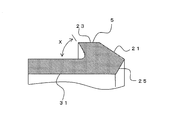
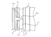
- FIG. 3 is a partial enlarged cross-sectional view of the ring member 5.
- FIG. 6 is a view showing a diameter-restricting rib 33 and a state in which the ring member 5 is located in a large diameter portion 13.
- FIG. 6 is a view showing a diameter-restricting rib 33 and a state in which the ring member 5 is located in a small diameter portion 17.
- FIG. 10B is a sectional view taken along line LL in FIG. 10A.
- FIG. 10B is a sectional view taken along line MM in FIG. 10A.
- FIG. The figure which shows the handhole 55.
- FIG. The figure which shows the connection structure 10a of the handhole 55 and the electric conduit 40a.
- the figure which shows the pipe joint 60d is the pipe joint 60d.
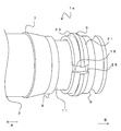
- FIG. 1 is an exploded perspective view of the male fitting portion 1a
- FIG. 2 is an assembled perspective view of the male fitting portion 1a
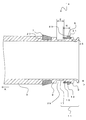
- FIG. 3 is a cross-sectional view of the male fitting portion 1a in the tube axis direction.
- the male fitting part 1a is mainly composed of a tubular body 3, a ring member 5, a water stop member 7, and the like.
- the male fitting portion 1 a is formed on the outer peripheral portion in the vicinity of the end portion of the tube body 3.
- the pipe body 3 is, for example, a flexible electric wire pipe, a pipe joint body, a bell block, and the like. Details of the form will be described later, but the form is not limited as long as an electric wire or the like can be inserted inside. Moreover, although the material of the pipe body 3 is not ask
- High-density polyethylene is polyethylene belonging to a crystalline thermoplastic resin in which ethylene as a repeating unit has few branches and is linearly bonded, and is also called hard polyethylene because of its relatively hard property.
- high density polyethylene is defined as polyethylene having a density of 0.942 or more.
- the copolymer of high density polyethylene is usually a crystalline resin having 1 to 5 branches relative to the ethylene monomer 1000.
- the homopolymer having a specific gravity of 0.97 has a crystallinity of over 75%, high rigidity, excellent tensile strength, impact strength, and cold resistance, and does not deteriorate the mechanical properties until low temperature of -80 ° C.
- the polarization in the molecule is small, the adhesion and printing processability are inferior, but the insulating property is excellent.
- a locking wall 9, a ring member arrangement portion 11, a locking wall 9, and a water stop member housing portion 27 are formed in this order from the tip.
- the opening side (in the direction of arrow B in the figure) of the tubular body 3 is defined as the distal end side of the tubular body 3
- the opposite side (in the direction of arrow A in the figure) is defined as the base side of the tubular body 3.
- the locking wall 9 is a part having a larger outer diameter than the surroundings.
- the pair of locking walls 9 are arranged to be separated from each other in the tube axis direction and regulate an operation range of the ring member 5 described later.
- the region sandwiched between the pair of locking walls 9 is the ring member placement portion 11.
- the ring member placement portion 11 includes a large diameter portion 13, a slope portion 15, and a small diameter portion 17 in order from the distal end side of the tube body 3. That is, a large diameter portion 13 is formed on the distal end side of the tube body 3 in the region sandwiched between the pair of locking walls 9, and on the base side of the tube body 3 in the region sandwiched between the pair of locking walls 9. A small diameter portion 17 is formed, and a slope portion 15 is formed between the large diameter portion 13 and the small diameter portion 17.
- the outer diameter of the large diameter portion 13 is smaller than the locking wall 9 and larger than the small diameter portion 17.
- the water stop member accommodating portion 27 is provided on the base side of the ring member arrangement portion 11. As shown in FIG. 3, the water stop member accommodating portion 27 is a groove having a substantially rectangular cross section, and the water stop member 7 is accommodated in the water stop member accommodating portion 27. That is, the water stop member 7 is provided further on the base side than the locking wall 9 on the base side of the male fitting portion 1a.
- the water stop member 7 is an annular member, and the inner diameter of the water stop member 7 is smaller than the outer diameter of the water stop member accommodation portion 27, and the inner surface of the water stop member 7 is formed on the outer surface of the water stop member accommodation portion 27. In close contact.
- the water-stop member 7 has a shape in which the inner peripheral portion of the cross-sectional shape is linear (substantially the same diameter in the tube axis direction), and the outer peripheral portion has a sloped portion from one end in the tube axis direction to the other. .
- the maximum outer diameter part of the water stop member 7 is arranged toward the base part side of the tube body 3, and the outer diameter of the part concerned is the tube 3 in the male fitting portion 1a.
- the water stop member 7 is larger than the maximum outer diameter and protrudes outward in the radial direction.
- the largest outer diameter part of the water stop member 7 may be formed not in the most base part side of the water stop member but in the middle between the front end part side and the base part side.
- the water stop member 7 is made of, for example, rubber or a water expansion member.
- rubber for example, ethylene propylene rubber (Ethylene Propylene Rubber) can be applied.
- Ethylene propylene rubber is a kind of synthetic rubber obtained by copolymerization of ethylene and propylene. In order to enable vulcanization with a sulfur compound, it is often used as an EPDM rubber obtained by copolymerizing a small amount of a diene monomer with ethylene propylene rubber.
- SBR, CR, NBR, ACM rubber, EPDM / PP dynamic cross-linked elastomer, and the like can also be used.
- the water stop member 7 is made of a water expansion member, for example, a nonwoven fabric made of polyester fiber and sodium polyacrylate fiber can be used.
- the ratio of the polyester fiber and sodium polyacrylate is 30% to 70% by mass, preferably 50 to 70% by mass, when the total of both is 100% by mass. is there.
- a binder resin having a low melting point in the range of 1 to 10% by mass, more desirably, based on the total of both polyester fibers and sodium polyacrylate fibers. 1 to 5% by mass.
- the binder resin low melting point polyester can be used, and the nonwoven fabric can be formed by a needle punch method.
- FIG. 4 is a diagram showing details of the cross-sectional shape of the ring member 5.
- the ring member 5 has a substantially C shape in which a part in the circumferential direction is cut by the cutting portion 19.
- a flat portion 31 is provided on the inner surface of the ring member 5 in the cross section of the ring member 5 in the tube axis direction.
- a claw portion 23 protruding in the radial direction is provided on the outer surface of the ring member 5.
- the claw portion 23 is formed on one end side of the ring member 5.
- the claw portion 23 has a turning angle (X in the figure) with respect to the outer surface of the ring member 5 of 90 ° or less.
- the turning angle of the claw portion 23 is larger in the range of 90 ° or less, and the tip of the claw portion 23 is not necessarily sharpened in a tapered shape, and a pressure receiving surface having a predetermined dimension may be formed.
- the folding angle may be 90 ° and may be formed at right angles to the outer surface of the flat portion.
- a tapered portion 21 is provided which is reduced in diameter from the outer surface of the ring member 5 (the outer surface of the claw portion 23) toward one end portion (right side in the drawing) of the ring member 5.
- a taper portion 25 is provided that expands from the inner surface of the ring member 5 toward one end portion (right side in the drawing) of the ring member 5. That is, a taper portion 21 (outer surface) and a taper portion 25 (tapered toward the one end portion (right side in the drawing) of the ring member 5 are formed on both the outer surface (the outer surface of the claw portion 23) and the inner surface of the ring member 5.
- An inner surface) is provided. That is, on the inner surface of the ring member 5, the portion excluding the taper portion 25 becomes the flat portion 31.
- the ring member 5 is disposed so that the side on which the tapered portions 21 and 25 described above are formed faces the distal end side of the tube body 3. That is, in the ring member 5, the tapered side by the tapered portions 21 and 25 is located on the distal end side of the tube body 3, and the other end portion, and the folding direction of the claw portion 23 faces the base side of the tube body 3.
- the inner diameter of the ring member 5 is smaller than the outer diameter of the locking wall 9, the ring member 5 is held between the locking walls 9.
- ABS resin for the ring member 5, for example, ABS resin, PP resin, hard vinyl chloride, or any of these and PC resin mixed resin or polymer alloy can be applied, and ABS resin (acrylonitrile butadiene styrene copolymer) is applied. It is desirable to do.
- ABS resin is a thermoplastic resin having a normal temperature of 70 to 100 ° C., and is excellent in balance of mechanical properties such as rigidity, hardness, workability, impact resistance, and bending fatigue. By adjusting the blending ratio of the raw materials, it is possible to achieve the above-mentioned property balance, excellent printing properties, good fluidity, good moldability for thin-walled products, etc., and excellent surface aesthetics. It is.
- the mechanical properties of the ABS resin include, for example, a tensile strength of about 39 MPa and a flexural modulus of about 64 MPa.
- a graft method As a method for producing an ABS resin, for example, a graft method is known.
- acrylonitrile, latex, styrene, a catalyst and an emulsifier are polymerized in a polymerization reactor, and moisture and the like are removed by a centrifuge and then pelletized by an extruder.
- each is polymerized using a polymerization reaction tank, unpolymerized monomers are recovered, and then pelletized by an extruder.
- rubber and additives are added to the AS resin, compounded with a mixer, and then pelletized with an extruder.
- a method in which an ABS resin having an extremely high butadiene ratio is produced by a graft method and compounded with an AS resin is also a kind of the same method.
- the length in the tube axis direction excluding the taper portion 25 of the ring member 5 is the length of the small diameter portion 17 of the ring member arrangement portion 11. (E in the drawing) is equal to or shorter than the length of the small diameter portion 17 of the ring member arrangement portion 11. Therefore, the ring member 5 has a clearance 29 between at least one of the locking walls 9 in a state where the ring member 5 is disposed in the ring member disposition portion 11. For this reason, the ring member 5 is slidable in the tube axis direction in the ring member arrangement portion 11.
- the entire ring member 5 except the tapered portion 25 is located in the small diameter portion 17. Therefore, when the ring member 5 moves to the distal end side of the tube body 3, at least a part of the ring member 5 is positioned on the outer periphery of the large diameter portion 13, and when the ring member 5 moves to the base side of the tube body 3, The ring member 5 is located in the small diameter portion. In this way, the ring member 5 can change into a state where the inner surface can be in contact with the large diameter portion 13 and a state where the inner surface can be in contact with the small diameter portion 17 depending on the position thereof.
- FIG. 5 is a diagram showing a state in which the male fitting portion 1a and the female fitting portion 30a are arranged to face each other and the male fitting portion 1a is inserted into the female fitting portion 30a.
- the tip of the male fitting part 1a is inserted into the female fitting part 30a.
- the female fitting portion 30 a is formed on the inner peripheral portion of the tube body 3.
- the female fitting portion 30a is expanded in diameter from the distal end side (opening side) in order from the cylindrical portion 35, the slope portion 37 that gradually decreases in diameter from the cylindrical portion 35, and the minimum inner diameter portion of the slope portion 37.
- a ring fitting part 39 is provided.
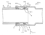
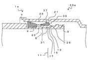
- FIG. 7a is an enlarged view of the vicinity of the ring member 5 in this state, and is an enlarged view of a portion H in FIG. 6b.
- the ring member 5 can slide within the ring member placement portion 11 until the tip of the ring member 5 contacts the locking wall 9. At this time, since the length excluding the taper portion 25 of the ring member 5 is equal to or shorter than the length of the small diameter portion 17, the entire ring member 5 is located in the range of the small diameter portion 17 and the slope portion 15. At this time, a clearance is generated between the inner surface of the ring member 5 and the small diameter portion 17.
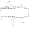
- FIG. 8b is a diagram showing the connection structure 10 obtained by connecting the male fitting portion 1a and the female fitting portion 30a.
- the tip of the claw portion 23 is fitted with the ring fitting portion 39 of the female fitting portion 30a. Therefore, even if the female fitting portion 30a is to be pulled out (arrow K in the figure), the movement of the ring member 5 is restricted by the locking wall 9, and the male fitting portion 1a is moved from the female fitting portion 30a. It will not be pulled out.
- the normal inner diameter of the ring member 5 substantially coincides with the large-diameter portion 13 of the male fitting portion 1a. For this reason, when the ring member 5 is in the position of the large diameter portion 13, sufficient clearance does not occur between the inner surface of the ring member 5 and the outer surface of the large diameter portion 13. For this reason, it is possible to suppress the ring member 5 from being reduced in diameter, and to prevent the fitting between the claw portion 23 and the ring fitting portion 39 from being released.
- the clearance between the inner surface of the ring member 5 and the outer surface of the large-diameter portion 13 is small. Since the clearance between the inner surface of the ring member 5 and the outer surface of the small diameter portion 17 is large, the diameter can be reduced. However, in addition to this, the diameter of the ring member 5 may be restricted by another structure.
- FIG. 9a is a view showing a state in which the diameter-restricting rib 33 is formed in the male fitting portion 1a.
- the diameter-restricting rib 33 is formed in a region sandwiched between the locking walls 9 and is formed with a predetermined dimension in the tube axis direction so as to continue from the large-diameter portion 13 to the small-diameter portion 17 across the slope portion 15.
- the outer surface of the diameter-restricting rib 33 is larger than the outer diameter of the large-diameter portion 13 and is, for example, a rib having the same height as the locking wall 9.
- the diameter-restricting rib 33 gradually decreases in width (circumferential length) as it goes from the large diameter portion 13 to the small diameter portion 17. That is, the width of the reduced diameter limiting rib 33 in the small diameter part 17 is narrower than the width of the reduced diameter limiting rib 33 in the large diameter part 13.
- the cut portion 19 of the ring member 5 is positioned on the reduced diameter restriction rib 33, and the reduced diameter restriction rib 33 is fitted into the cut portion 19. If the width of the reduced diameter limiting rib 33 in the small diameter part 17 becomes narrower than the width of the reduced diameter limiting rib 33 in the large diameter part 13, the width of the reduced diameter limiting rib 33 does not change gradually. Also good. For example, in the vicinity of the boundary between the large diameter portion 13 and the small diameter portion 17 (the slope portion 15), the width of the diameter reduction limiting rib 33 may be changed to be a step.
- the width of the reduced diameter limiting rib 33 is substantially equal to the width (circumferential length) of the cut portion 19. Therefore, even if the ring member 5 attempts to reduce the diameter, the circumferential end face of the ring member 5 in the cutting portion 19 comes into contact with the reduction diameter limiting rib 33, and further diameter reduction is restricted.
- the width of the reduced diameter limiting rib 33 is sufficiently narrower than the width (circumferential length) of the cut portion 19. For this reason, a clearance is generated between the circumferential end surface of the ring member 5 in the cut portion 19 and the diameter-restriction limiting rib 33. For this reason, the ring member 5 can be reduced in diameter.
- the maximum thickness of the ring member 5 (height from the flat part 31 to the tip of the claw part 23) is determined when the male fitting part 1a is inserted into the female fitting part 30a.
- the radial clearance between the small-diameter portion 17 of la and the minimum inner diameter portion of the slope portion 37 of the female fitting portion (the outer diameter of the small-diameter portion 17 of the male fitting portion 1a and the slope portion 37 of the female fitting portion).
- the clearance is smaller than the minimum inner diameter). Accordingly, the ring member 5 can be reduced in diameter at the position of the small diameter portion 17. At this time, when the minimum inner diameter portion of the slope portion 37 of the female fitting portion passes through the ring member 5, the ring member 5 is expanded in diameter.
- the claw portion 23 can get over the slope portion 37 of the female fitting portion 30a.
- the maximum thickness of the ring member 5 (height from the flat portion 31 to the tip of the claw portion 23) is set so that the male fitting portion 1a is inserted when the male fitting portion 1a is inserted into the female fitting portion 30a.
- Radial clearance of the enlarged diameter portion by the ring fitting portion 39 of the large diameter portion 13 and the female fitting portion 30a (the outer diameter of the large diameter portion 13 of the male fitting portion 1a and the expansion by the ring fitting portion 39). Smaller than the clearance due to the difference from the inner diameter of the diameter portion. For this reason, the ring member 5 is fitted with the ring fitting portion 39 of the female fitting portion 30 a while the diameter of the ring member 5 is restricted at the position of the large diameter portion 13.
- the ring member 5 is restricted in its diameter at the position of the large diameter portion 13 and can be reduced at the position of the small diameter portion 17 depending on the position thereof. can do.
- the taper angle of the taper portion 25 of the ring member 5 (in the tube axis direction cross section of the male fitting portion 1a)
- the angle formed by the extension line of the flat part 31 and the taper part 25 is the taper angle of the slope part 15 of the male fitting part 1a (the extension line of the small diameter part 17 in the cross section in the tube axis direction of the male fitting part 1a). It is desirable to make the taper angle of the taper portion 25 of the ring member 5 larger or the same as the angle between the slope portion 15 and the inclined surface portion 15.
- the outer peripheral surface of the water stop member 7 is in close contact with the inner surface of the cylindrical portion 35 of the female fitting portion 30a. That is, the gap between the male fitting portion 1a and the female fitting portion 30a can be filled with the water stop member 7. For this reason, it is possible to prevent moisture from entering the connection structure 10 from the outside.
- the female fitting portion 30 a is inserted into the female fitting portion 30 a when the male fitting portion 1 a is pushed into the female fitting portion 30 a. Until it comes into contact with the water stop member 7, the water stop member 7 does not receive resistance. For this reason, the pushing resistance to the female fitting part 30a of the male fitting part 1a can be made small.
- each shape of the male fitting part 1a and the female fitting part 30a is made of a material having sufficient strength, and is attached to the tensile tester in a state where both are fitted, and the tensile tester is used.
- a pulling load was obtained by applying a load.
- the drawing load satisfied 100 kg. Therefore, it was confirmed that the pull-out force of the joint portion has a sufficient pull-out force.
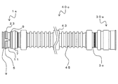
- FIG. 10 is a diagram showing the conduit 40a.
- the conduit 40a has a fitting structure at both ends, and is formed at a male fitting portion 1a formed at one end of the tube 3a and at the other end of the tube 3a. And a female fitting portion 30a having a shape that can be fitted to the portion 1a.
- a female fitting portion 30a having a shape that can be fitted to the portion 1a.
- a spiral wave shape 41 having a continuous predetermined pitch is formed on the outer peripheral surface of the tube body 3a between the male fitting portion 1a and the female fitting portion 30a.
- a plurality of conduits 40a can be connected to each other.
- the method for connecting the conduit 40a is the same as the method for connecting the male fitting portion 1a and the female fitting portion 30a described above. That is, a plurality of conduits 40a are provided, a male fitting portion 1a of one conduit 40a is inserted into a female fitting portion 30a of another conduit 40a, and the male of one conduit 40a is inserted.
- connection structure for a conduit tube in which the mold fitting portion 1a and the female mold fitting portion 30a of another conduit tube 40a are fitted and connected. For this reason, the connection between the conduits 40a does not require screwing such as a spiral joint, so that the construction is easy.
- FIG. 11a is a diagram showing the conduit 40b.
- 11b is an enlarged cross-sectional view of the vicinity of the portion N in FIG. 11a
- FIG. 12a is a cross-sectional view taken along line LL in FIG. 11a
- FIG. 12b is a cross-sectional view taken along line MM in FIG.
- the conduit 40b is different in that a tube 3b is applied instead of the tube 3a of the conduit 40a.
- a peak part 43 (large diameter part) and a trough part are formed on the outer peripheral surface of the tube 3b.
- 45 small-diameter portions are alternately formed.
- the mountain portion 43 has a substantially square cross section, and the valley portion 45 has a circular cross section.
- the diameter of the peak portion 43 (the length of one side) is larger than the outer diameter of the valley portion 45.
- the conduits 40b can be stably arranged when the conduits 40b are stacked.
- the maximum outer diameter of the female fitting portion 30a is smaller than the diameter of the peak portion 43 (length of one side). Therefore, the female fitting portion 30 a does not protrude from the outer periphery of the peak portion 43 when viewed from the end on the female fitting portion 30 a side. Therefore, when the mountain parts 43 are brought into contact with each other and the electric conduit 40b is stacked, the female fitting portion 30a does not interfere with the adjacent electric conduit 40b.
- a pair of protrusions 47 are formed at a substantially central portion of the valley 45 with respect to the tube axis direction of the tube 3b.
- a flat portion 49 is formed between the protrusions 47 in the cross section in the tube axis direction of the tube body 3b.
- FIG. 13 is a diagram showing the conduit 40c.
- the conduit 40c is different in that a tube 3c is applied instead of the tube 3a of the conduit 40a.
- substantially square ridges 43 and circular valleys 45 are alternately formed in the same manner as the tubular body 3b.
- the trough 45 of the tubular body 3 c is sufficiently longer than the length of the crest 43. Moreover, the trough part 45 is formed in a waveform in the cross section in the tube axis direction of the tube body 3c. In addition, the maximum outer diameter of the waveform in the valley portion 45 is smaller than the outer diameter of the peak portion 43. Similarly to the electric conduit 40b, the electric conduit 40c can be stably arranged when the electric conduits 40c are stacked by providing the substantially square peaks 43.
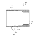
- FIG. 14 is a cross-sectional view of the bell block 50.
- the bell block 50 can be connected to the conduit 40b and the like, and has the same structure as the female fitting portion 30a. That is, on the inner surface on one end side of the bell block 50, the cylindrical portion 35, the slope portion 37 that gradually decreases in diameter from the cylindrical portion 35, and the slope portion 37 in order from one tip side (opening side). It has the ring fitting part 39 expanded from the minimum inner diameter part.
- a bell mouth 53 whose inner diameter gradually increases toward the opening end is formed at the other end of the bell block 50.
- the bell block 50 is connected by inserting a male fitting portion 1a such as a conduit 40b on the female fitting portion 30a side. Moreover, from the bell mouth 53, an electric wire etc. can be penetrated inside.
- FIG. 15 is a diagram showing a handhole 55 having a plurality of bell blocks 50.
- the hand hole 55 is, for example, a concrete box shape, and the bell block 50 is embedded in the concrete. That is, a plurality of through holes are formed in the side surface of the concrete handhole 55 by the bell block 50.
- a connection hole may be formed in the hand hole 55, and the bell block 50 inserted into the connection hole may be fixed with a mortar or an epoxy putty to fix the bell block 50 to the hand hole 55.
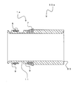
- FIG. 16 is a cross-sectional view showing a connection structure 10a between the bell block 50 and the conduit 40b provided in the hand hole 55. As shown in FIG. In addition, it can replace with the electric conduit 40b, and can also apply another electric conduit. As described above, a plurality of bell blocks 50 are arranged in the hand hole 55. The conduit 40b is connected to part or all of the bell block 50. That is, the connection structure 10a includes a hand hole 55 having a bell block 50 and a conduit 40b, the bell block 50 having the same structure as the female fitting portion 30a, and the male fitting portion 1a of the conduit 40b. And connected.
- the method for connecting the conduit 40b and the bell block 50 is the same as the method for connecting the conduits described above. That is, instead of the female fitting portion 30a of one conduit 40b, the male fitting portion 1a is inserted into the female fitting portion 30a of the bell block 50 in the same procedure as described above. That's fine. By doing in this way, the connection structure of the conduit tube in which the hand hole 55 having the bell block 50 having the same structure as the female fitting portion 30a of the conduit tube and the male fitting portion 1a of the conduit tube 40b are connected. 10a can be obtained.
- the peak portion 43 of the electric conduit 40b is a rectangular electric conduit
- the electric conduits 40b can be stacked in multiple stages and can be arranged in a compact manner. For this reason, it is possible to reduce the amount of earth and sand dug when the conduit 40b is buried, and it is possible to backfill all at once, so that the work load is reduced. As a result, the construction period can be shortened and the construction cost can be reduced.
- the conduit 40b of the present invention can connect the conduits 40b by simply inserting the male fitting portion 1a into the female fitting portion 30a. Therefore, different from the electric pipe connected by the pipe joint having the spiral groove, for example, the fixed electric pipes 40b can be directly connected to each other.
- connection of the handhole 55 and the conduit 40b has a bell mouth which has a fitting part which fits with the female fitting part 30a other than connecting with the male fitting part 1a of the conduit 40b. Also good.
- FIG. 17 shows the bell block 50a.
- a member that can be connected to the various conduits described above and has at least one of the same structure as the male fitting portion 1a or the female fitting portion 30a is referred to as a pipe joint. There is a case.
- the bell block 50a includes a male fitting portion 1a. That is, the bell block 50 a has the same structure as the male fitting portion 1 a at one end and the bell mouth 53 at the other end. In this case, the male fitting portion 1a can be connected to the female fitting portion 30a of the conduit by projecting from the outer surface of the hand hole 55.
- FIG. 18a is a view showing a pipe joint 60a. Both ends of the pipe joint 60a have the same structure as the male fitting portion 1a.
- the pipe joint 60a it is possible to connect the electric pipes having the female fitting part 30a at the end part.
- the conduits having female fitting portions 30a at both ends it is possible to connect the conduits having female fitting portions 30a at both ends.
- the female fitting part 30a of a conduit tube can also be converted into the male fitting part 1a.
- the bell block 50 having the shape of the female fitting portion 30a is disposed in the two hand holes 55 facing each other.
- the male fitting part 1 a is fixed to the hand hole 55 by inserting the male fitting part 1 a into the bell block 50 of one hand hole 55.
- the conduit is extended by connecting the male fitting portion 1a of the next conduit 40b to the female fitting portion 30a at the other end of the conduit 40b after the fitting.
- the male fitting portion 1a of the conduit 40b is also inserted and connected to the bell block 50 of the other hand hole 55 facing each other.
- the pipe line is extended by connecting the adjacent male fitting part 1a of the next electric pipe 40b to the female fitting part 30a at the other end of the electric pipe 40b after the fitting.
- the conduit 40 b is provided with the two protrusions 47 facing the valley 45, and a groove shape is formed between the protrusions 47.
- a groove shape is formed between the protrusions 47.
- the electric conduit 40b is provided with two protrusions 47 facing the valley 45, and by forming a groove shape between the protrusions 47, a blade can be used along the groove. For this reason, it is easy to grasp the cutting position, and it is possible to suppress the cutter from sliding. For this reason, the cutting position is not shifted or cut obliquely.
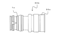
- FIG. 18b is a diagram showing the pipe joint 60b.
- One end of the pipe joint 60b has the same structure as the male fitting part 1a, and the other end has the same structure as the female fitting part 30a.
- the pipe joint 60b it is possible to connect a conduit having a male fitting portion 1a at at least one end and a conduit having a female fitting portion 30a at at least one end. it can.
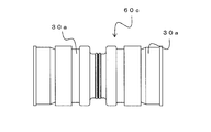
- FIG. 19a is a view showing a pipe joint 60c. Both ends of the pipe joint 60c have the same structure as the female fitting part 30a.
- the electric pipes having the male fitting portion 1a at one end can be connected to each other.
- the conduits having both male fitting portions 1a at both ends can also be converted into the female fitting part 30a.
- FIG. 19b is a diagram showing the pipe joint 60d.
- One end of the pipe joint 60d has the same structure as the female fitting part 30a, and the other end has a spiral wave shape 61 continuous with the outer surface (and the inner surface) of the tube.
- the pipe joint 60d it is possible to connect a conduit having the male fitting portion 1a at at least one end thereof and a conduit having a spiral wave shape on the outer surface.
- the electric pipes having different cross-sectional shapes of the electric pipe having the square cross-sectional shape as in the present invention and the electric pipe having the spiral wave shape on the outer surface can be obtained. Dissimilar pipe joints can be realized.
- the ring member 5 used for the connecting portion such as the conduit is arranged on the outer surface of the male fitting portion 1a, the ring member 5 can be easily visually recognized. it can.
- the ring member 5 is slidable within the ring member arrangement portion 11, when the male fitting portion 1a is pushed into the female fitting portion 30a, the vicinity of the end portion of the ring member 5 has a large diameter. It can be moved from the portion 13 to the small diameter portion 17. For this reason, the diameter of the ring member 5 having a C-shaped cross section can be easily reduced.
- the diameter of the ring member 5 can be easily reduced even if the thickness of the claw portion 23 of the ring member 5 to which a pulling force is applied is increased.
- the male fitting portion 1a and the female fitting portion 30a can be easily connected, and the male fitting portion 1a can be reliably prevented from coming off from the connected state.
- the ring member 5 moves to the position of the large diameter portion 13. For this reason, the diameter reduction of the ring member 5 can be suppressed. Such an effect can also be obtained by the diameter-restricting rib 33.
- the water stop member 7 is arranged on the base side from the ring member 5, when the male fitting portion 1a is inserted into the female fitting portion 30a, it is difficult to receive insertion resistance due to the water stopping member 7. be able to. Even if a lubricant is applied to the water stop member 7, the lubricant does not adhere to the ring member 5.
- conduit 40a and the like have the male fitting portion 1a at one end and the female fitting portion 30a at the other end, it is easy to connect the plurality of conduits 40a to each other. It is.
- the conduit 40b has a substantially square peak portion 43 and a circular valley portion 45 formed alternately on the outer peripheral surface of the tube body. Therefore, when the plurality of conduit tubes 40b are stacked, the conduit tube 40b is stable.
- the conduit 40b can be stacked.
- the conduit 40b has a pair of protrusions 47 formed at a substantially central portion of the valley 45 with respect to the tube axis direction of the tube body, and a groove shape is formed between the protrusions 47.
- the conduit 40a can be easily cut. Therefore, it is possible to maintain a high accuracy of the cutting position of the cut pipe, and to construct a highly accurate conduit connection structure and a conduit of the conduit.
- various conduits can be easily connected by using a pipe joint having a male fitting part 1a or a female fitting part 30a at at least one end.
- a bell block and a conduit can be easily connected by using the bell block which comprises the male fitting part 1a or the female fitting part 30a in one edge part.
Landscapes
- Engineering & Computer Science (AREA)
- General Engineering & Computer Science (AREA)
- Mechanical Engineering (AREA)
- Architecture (AREA)
- Civil Engineering (AREA)
- Structural Engineering (AREA)
- Joints With Sleeves (AREA)
- Joints That Cut Off Fluids, And Hose Joints (AREA)
- Laying Of Electric Cables Or Lines Outside (AREA)
- Quick-Acting Or Multi-Walled Pipe Joints (AREA)
Abstract
一対の係止壁9で挟まれた領域が、リング部材配置部11となる。リング部材配置部11は、管体3の先端側から順に、大径部13、斜面部15、小径部17から構成される。リング部材配置部11には、リング部材5が配置される。リング部材5は、円周方向の一部が切断部19で切断された略C字状である。リング部材5のテーパ部25を除く管軸方向の長さは、リング部材配置部11の小径部17の長さと等しいか、リング部材配置部11の小径部17の長さよりも短い。すなわち、リング部材5の管軸方向の長さはリング部材配置部11の管軸方向の長さよりも短い。したがって、リング部材5は、リング部材配置部11において、管軸方向にスライド可能である。
Description
本発明は、電線を保護するための電線管、電線管の接続構造、ベルブロック、電線管同士の接続方法、電線管とベルブロックの接続方法、管継手、およびリング部材に関する。
従来、例えば地中に電線管が埋設されて用いられる。この場合、複数の電線管が併設して埋設される。また、それぞれの電線管は、所定の長さで製造・運搬されるため、複数の電線管が管継手や嵌合構造などによって接続部で接続されて用いられる。
このような電線管の接続構造としては、例えば、螺旋管からなる管継手が提案されている(特許文献1)。
特許文献1では、外面螺旋状の電線管の端部(雄型構造)を、管継手の内面螺旋形状(雌型構造)に回転させてねじ込むことで接続が行なわれる。さらに、雄型継手部の外周と雌型継手部の内周面に水膨張部材が設けられて止水が行なわれる。
また、コンパクトかつ容易に波付き可撓管同士を接合でき、衝撃等においても簡単に管継手から脱落することがない抜け止めリングが提案されている(特許文献2)。
特許文献2では、ケーブル等の保護管である電線管の接続に使用される雌型嵌合部内に抜け止めリングが配置される。雌型嵌合部に挿入された雄型嵌合部が、抜け止めリングによって、雌型嵌合部から抜けることを防止することができる。この際、抜け止めリングの形状を適正にすることで、抜け止めリングの装着が容易である。
より詳細には、特許文献2の発明の抜け止めリングは、リング状の本体部と、本体部の半径方向内側へ曲げられた複数の爪部と、本体部の外周面に設けられ、本体部の外周側に突出した複数のストッパとを具備するものである。
ここで、抜け止めリングのストッパは、第1の一対のストッパと、第2の一対のストッパからなり、第1の一対のストッパは、本体部に対して互いに対向する位置に設けられ、第2の一対のストッパは、本体部に対して互いに対向する位置に設けられる。また、ストッパの内、少なくとも第2の一対のストッパの外面には、本体部の管軸方向に対して傾斜する傾斜部が設けられる。第2の一対のストッパに設けられる傾斜部の傾斜角は、本体部の管軸方向に対して互いに反対を向いて形成される。
特許文献2の発明によれば、抜け止めリングを、電線管の雌管継手に装着する時に、抜け止めリングが管の内部で倒れたり、電線管の内壁自体に取付けるのに手間がかかるなどの問題を解決することができる。また、同時に、トラックなどからの荷下ろしの際の衝撃で、C文字型の抜け止めリングが一時的に縮径して、抜け止めリングが管継手から抜け落ちることを防止することができる。
また、この他に、管軸方向両端に受口および差口が形成され、差口の近い位置にゴム輪を有し、さらにゴム輪の奥側に抜け止めリングを有し、差口を受口に挿入することが可能な波付合成樹脂管が提案されている(特許文献3)。
特許文献3において、ゴム輪より先端側の受口の第2所定位置には、リングを受容し、かつリングと協働して抜けを防止する溝が形成される。特許文献3は、波付合成樹脂管と、この波付合成樹脂管を用いた接続構造に関するものである。また、特許文献3の発明において、外周面に山部と谷部とが交互に形成された波付合成樹脂管に装着されるリングは、それぞれ周方向の一部が切断された2つのリング部材が管軸方向に重ね合わせられて形成される。差口を受口に挿入するときには、この2つのリング部材の双方が縮径する。一方、差口を引き抜く時には、波付合成樹脂管が一方のリング部材に当接するため、一方のリング部材が縮径しても、他方のリング部材は開いたままとなる。このため波付合成樹脂管の引き抜きが規制される。
また、ハンドホールに用いられる電線管を保護するためのブロック体に、電線管の抜け止め構造を設ける旨が提案されている(特許文献4)。
特許文献4では、ブロック体は、外形が略立方体または略直方体であり、貫通孔が形成れる。貫通孔には、略円形状の断面形状が、管軸方向に凹凸状にブロックの表面側から裏面側に連続する。この貫通孔の凹部には、係止片を有する抜け止め部材が装着される。
しかし、特許文献1は、螺旋形状の波付管の接続に用いられるものであり、適用可能な管体の形状に制約がある。また、接続時には、管継手をねじ込む必要があることから、接続作業に時間を要する。また、管継手の外径が管体の外径よりも大きくなるため、例えば複数の電線管を積層させて地中に配置する際に、継手部分が不安定になる。
また、特許文献2は、雌型嵌合構造の内部に挿入される抜け止めリングに関するものであるが、組み立てる際に、抜け止めリングを雌型嵌合部の内部に挿入する作業性が悪い。また、組み立て後の状態を視認することができないため、抜け止めリングの付け忘れや、運搬時の脱落等に気づかない場合もある。
また、特許文献3は、雄部の差し込み口側の近い位置にゴム輪を有し、さらに雄部の奥側に抜け止めリングを有するものである。拡径リングは、雄部の周期的に設けられる波付け部の溝に落とし込まれるものであるが、特許文献3では、ゴム輪が雄部の差込み口側に近い位置に設けられる。このため、さらに雌型継手部に雄型継手部を奥深く挿入して、抜け止めリングと嵌合させる際には、ゴム輪部の挿入抵抗が大きくなるため、場合により、ゴム輪部に滑剤を塗布する必要がある
また、特許文献4では、係止片の一部がブロック本体に埋め込まれているため、製造性が悪いとともに、特許文献2と同様に、係止片を外部から視認することができない。
本発明は、このような問題に鑑みてなされたもので、組立作業性に優れ、接続が容易な、電線管、電線管の接続構造、ベルブロック、電線管同士の接続方法、電線管とベルブロックの接続方法、管継手、およびこれらに用いられるリング部材を提供することを目的とする。
前述した目的を達するために第1の発明は、管体の端部近傍の外周部に形成される雄型嵌合部を有する電線管であって、管軸方向に離間して配置される一対の係止壁と、前記係止壁で挟まれた領域に配置されるリング部材と、を具備し、前記リング部材は、円周方向の一部が切断された略C字状であり、前記リング部材の管軸方向の断面において、前記リング部材は、内面が平坦であり、外面に爪部を有し、外面及び内面の両者に前記リング部材の一方の端部に向かって先細りとなるテーパ部を有し、前記リング部材は、前記テーパ部による先細り側が前記管体の先端側に位置するように配置され、前記係止壁は、前記係止壁で挟まれた領域の、前記管体の先端側には大径部が形成され、前記係止壁で挟まれた領域の前記管体の基部側には小径部が形成され、前記大径部と前記小径部との間に斜面部が形成され、前記リング部材の前記テーパ部を除く管軸方向の長さは、前記小径部の長さと等しいか、前記小径部の長さよりも短く、前記リング部材は、少なくとも一方の前記係止壁との間にクリアランスを有し、前記リング部材が、前記大径部または前記小径部のいずれかの位置にスライド可能であることを特徴とする電線管である。
また、第1の発明では、前記雄型嵌合部の基部側の前記係止壁よりもさらに基部側に、止水部材が設けられる電線管としても良い。
前記係止壁で挟まれた領域には、前記大径部から前記斜面部を挟んで前記小径部に連続し、前記大径部の外径より大径の縮径制限リブが、管軸方向に所定寸法にて形成され、前記縮径制限リブに前記リング部材の切断部が嵌る雄型嵌合部を有していても良い。
第1の発明においては、後述するように、管体の開口部側を管体の先端側とし、その逆側である管体の長手方向の奥側を管体の基部側と規定する。
第1の発明によれば、リング部材を雄型嵌合部の外面に配置したことで、リング部材を容易に視認することができる。
また、リング部材が、雄型嵌合部の外面に形成された大径部と小径部とにそれぞれ移動可能であるため、大径部に位置する際には、リング部材の縮径が規制され、小径部に位置する際には、リング部材が縮径可能となる。このため、雌型嵌合部との嵌合時は、リング部材が小径部に移動して、容易に縮径することが可能となる。また、雌型嵌合部と接続された後は、雄型嵌合部を引き抜こうとしても、リング部材が大径部に位置するため、縮径が規制され、雌型嵌合部との嵌合が外れることを抑制することができる。
このように、第1の発明は、雌型嵌合部に形成されたリング嵌合部によって雄型嵌合部がロックされるもので、リング部材の爪部が、リング嵌合部を越えた瞬間にロックがかかるものである。また、リング部材の爪部自体が弾性変形して雌型嵌合部のリング嵌合部を超えるものではなく、リング部材に切断部があるので、リング部材全体で縮径するものである。このため、引き抜き力がかかる爪部の肉厚を大きくしても、容易に縮径することができる。
第2の発明は、両端に嵌合構造を有する電線管であって、管体と、前記管体の一方の端部に形成された雄型嵌合部と、前記管体の他方の端部に形成され、前記雄型嵌合部と嵌合可能な形状を有する雌型嵌合部と、を具備し、前記雄型嵌合部は、前記管体の外周部に形成され、管軸方向に離間して配置される一対の係止壁と、前記係止壁で挟まれた領域に配置されるリング部材と、を具備し、前記リング部材は、円周方向の一部が切断された略C字状であり、前記リング部材の管軸方向の断面において、前記リング部材は、内面が平坦であり、外面に爪部を有し、外面及び内面の両者に前記リング部材の一方の端部に向かって先細りとなるテーパ部を有し、前記リング部材は、前記テーパ部による先細り側が前記管体の先端側に位置するように配置され、前記係止壁は、前記係止壁で挟まれた領域の、前記管体の先端側には大径部が形成され、前記係止壁で挟まれた領域の前記管体の基部側には小径部が形成され、前記大径部と前記小径部との間に斜面部が形成され、前記リング部材の管軸方向の長さは、前記小径部の長さよりも短く、前記リング部材は、少なくとも一方の前記係止壁との間にクリアランスを有し、前記リング部材が、前記大径部または前記小径部のいずれかの位置にスライド可能であり、前記雌型嵌合部は、前記管体の内周部に形成され、先端側から、筒状部と、前記筒状部から徐々に縮径する斜面部と、前記斜面部の最小内径部から拡径したリング嵌合部と、を具備することを特徴とする電線管である。
前記係止壁で挟まれた領域には、前記大径部から前記斜面部を挟んで前記小径部に連続し、前記大径部の外径より大径の縮径制限リブが、前記大径部における前記縮径制限リブの幅よりも前記小径部における前記縮径制限リブの幅が狭く形成され、前記縮径制限リブに前記リング部材の切断部が嵌ってもよい。
前記雄型嵌合部の基部側の前記係止壁よりもさらに基部側に、止水部材が設けられてもよい。
前記雄型嵌合部と前記雌型嵌合部の間において、前記管体の外周面に連続した所定ピッチの螺旋状の波形状が形成されてもよい。
前記雄型嵌合部と前記雌型嵌合部の間において、前記管体の外周面に略正方形状の山部としての大径部と、円形状の谷部として小径部が交互に形成されてもよい。
前記管体の管軸方向に対する前記谷部としての小径部の略中央部に、一対の突起部が形成され、前記管体の管軸方向断面において、前記突起部の間に平坦部が形成されてもよい。
前記管体の管軸方向断面において、前記谷部としての小径部が波形に形成されてもよい。
前記止水部材は、前記雄型嵌合部の基部側の前記係止壁よりもさらに基部側に形成された止水部材収容部に配置されてもよい。
前記リング部材は、ABS樹脂、PP樹脂、硬質塩化ビニルまたはこれらのいずれかとPC樹脂の混合樹脂またはポリマーアロイのいずれかであってもよい。
前記止水部材は、ゴム製または水膨張部材のいずれかであってもよい。
第2の発明によれば、第1の発明と同様の効果を得ることができる。また、他方の端部に雌型嵌合部を有するため、複数の電線管同士を接続するのが容易である。
また、係止壁で挟まれた領域に縮径制限リブを設けることで、リング部材が大径部に位置する際には、切断部におけるリング部材の端面と縮径制限リブとの接触によって、縮径が制限される。一方、リング部材が小径部に位置する際には、切断部におけるリング部材の端面と縮径制限リブと間に十分なクリアランスが形成されるため、リング部材の縮径が許容される。
また、第2の発明にかかる電線管は、管体の外周面に螺旋状の波形状を形成することもできる。すなわち、従来の螺旋波付管に対して、雄型嵌合部と雌型嵌合部を設けることができる。
また、第2の発明にかかる電線管は、管体の外周面に略正方形状の山部と、円形状の谷部とが交互に形成されてもよい。すなわち、電線管を角型電線管としてもよい。このようにすることで、複数の電線管を積層する際に、安定して電線管を積み上げることができる。
この際、管体の管軸方向に対する谷部の略中央部に、一対の突起部が形成され、突起部の間に溝形状が形成されれば、当該部位で、容易に電線管を切断することができる。このため、電線管の長さ調整が容易である。
なお、略正方形の山部と山部の間の谷部を波形としてもよい。このようにすることで、より電線管の可撓性を高めることができる。
また、リング部材の材質を適切に選定することで、適度な弾性力と、引き抜き力に耐える強度とを両立することができる。
また、止水部材としては、ゴム製または水膨張部材のいずれかを選択することができる。
第3の発明は、第2の発明にかかる電線管の接続構造であって、複数の前記電線管を用い、一の前記電線管の前記雄型嵌合部と、他の前記電線管の前記雌型嵌合部とが嵌合して接続され、前記リング部材の最大厚みは、前記雄型嵌合部の前記小径部と前記雌型嵌合部の前記斜面部の最小内径部との径方向クリアランスおよびより前記雄型嵌合部の前記大径部と前記雌型嵌合部のリング嵌合部の径方向クリアランスも小さいことを特徴とする電線管の接続構造である。
また、第3の発明は、第2の発明にかかる電線管の接続構造であって、ベルブロックを有するハンドホールと、前記電線管を用い、前記雌型嵌合部と同一構造を有する前記ベルブロックと、前記電線管の前記雄型嵌合部とが接続されることを特徴とする電線管の接続構造である。
前記ハンドホールは、複数の前記ベルブロックを有し、前記電線管は、前記ベルブロックの一部またはすべてと接続されてもよい。
第3の発明によれば、接続作業が容易な電線管同士または電線管とベルブロックとの接続構造を得ることができる。
第4の発明は、第2の発明にかかる電線管と接続可能であり、前記雌型嵌合部と同一構造を有することを特徴とするベルブロックである。
第4の発明によれば、電線管との接続が容易な、ベルブロックを得ることができる。
第5の発明は、第2の発明にかかる電線管同士の接続方法であって、前記雄型嵌合部の先端を前記雌型嵌合部に挿入する工程と、前記雌型嵌合部の前記斜面部に、前記係止壁で挟まれた領域に配置された前記リング部材の外周の前記テーパ部を接触させて、前記リング部材を前記雄型嵌合部の前記小径部までスライド移動させて縮径し、前記リング部材を前記雄型嵌合部の前記小径部に収納する工程と、前記爪部の端部が前記雌型嵌合部の前記斜面部を通り抜けることで、前記爪部が、前記雌型嵌合部の前記斜面部の基部側に形成された前記リング嵌合部に収納されることを特徴とする電線管同士の接続方法である。
また、第5の発明は、第2の発明にかかる電線管とベルブロックとの接続方法であって、前記ベルブロックは、前記電線管の前記雌型嵌合部と同一の構造を有し、前記雄型嵌合部の先端を前記ベルブロックに挿入する工程と、前記ベルブロックの前記斜面部に、前記係止壁で挟まれた領域に配置された前記リング部材の外周の前記テーパ部を接触させて、前記リング部材を前記雄型嵌合部の前記小径部までスライド移動させて縮径し、前記リング部材を前記雄型嵌合部の前記小径部に収納する工程と、前記爪部の端部が前記ベルブロックの前記斜面部を通り抜けることで、前記爪部が、前記ベルブロックの前記斜面部の基部側に形成された前記リング嵌合部に収納されることを特徴とする電線管とベルブロックの接続方法である。
第5の発明によれば、電線管同士または電線管とベルブロックとを、容易に接続することができる。
第6の発明は、第2の発明にかかる電線管と接続可能であり、少なくとも一方の端部が前記雄型嵌合部と同一構造を有することを特徴とする管継手である。
この場合、両方の端部が前記雄型嵌合部と同一構造を有してもよい。また、一方の端部が前記雄型嵌合部と同一構造を有し、他方の端部がベルマウスであってもよい。
また、第6の発明は、第2の発明にかかる電線管と接続可能であり、少なくとも一方の端部が前記雌型嵌合部と同一構造を有することを特徴とする管継手である。
この場合、一方の端部が前記雌型嵌合部と同一構造を有し、他方の端部がベルマウスであってもよい。また、一方の端部が前記雌型嵌合部と同一構造を有し、他方の端部が前記管体の外表面に連続した螺旋状の波形状を有してもよい。
第6の発明によれば、電線管の雄型嵌合部または雌型嵌合部と接続することが可能な管継手を得ることができる。
第7の発明は、電線管の接続部に用いられるリング部材であって、前記リング部材は、円周方向の一部が切断された略C字状であり、前記リング部材の管軸方向の断面において、内面が平坦であり、外面に爪部を有し、外面及び内面の両者に前記リング部材の一方の端部に向かって先細りとなるテーパ部を有することを特徴とするリング部材である。
第7の発明によれば、雄型嵌合部に使用した際に、雌型嵌合部との嵌合が容易であり、接続作業が容易な雄型嵌合部を得ることができる。
本発明によれば、組立作業性に優れ、接続が容易な、電線管、電線管の接続構造、ベルブロック、電線管同士の接続方法、電線管とベルブロックの接続方法、管継手、およびこれらに用いられるリング部材を提供することができる。
以下、図面を参照しながら、本発明の実施形態について説明する。図1は、雄型嵌合部1aの分解斜視図であり、図2は、雄型嵌合部1aの組立斜視図である。また、図3は、雄型嵌合部1aの管軸方向の断面図である。雄型嵌合部1aは、主に、管体3、リング部材5、止水部材7等から構成される。雄型嵌合部1aは、管体3の端部近傍の外周部に形成される。
管体3は、例えば可撓性を有する電線管や、管継手本体、ベルブロックなどであり、形態の詳細は後述するが、内部に電線等を挿通可能であればその態様は限定されない。また、管体3の材質は問わないが、例えば樹脂製であり、高密度ポリエチレン製であることが望ましい。
高密度ポリエチレンは、繰り返し単位のエチレンが分岐をほとんど持たず直鎖状に結合した、結晶性の熱可塑性樹脂に属するポリエチレンで、比較的に硬い性質から硬質ポリエチレンとも呼ばれる。旧JIS K6748:1995において高密度ポリエチレンとは密度0.942以上のポリエチレンと定義されている。高密度ポリエチレンのコポリマーは、通常ではエチレンモノマー1000に対し1~5の分岐を持つ結晶性樹脂である。比重0.97のホモポリマーの結晶化度は75%を越え、剛性が高く、引張り強さや衝撃強さ、耐寒性に優れ、-80℃の低温下まで機械的特性が低下しない。また、分子内の分極が少ないため、接着や印刷加工性に劣るが、絶縁性に優れるという性質を持つ。
管体3の端部には、先端から順に、係止壁9、リング部材配置部11、係止壁9、止水部材収容部27が形成される。なお、以下の説明において、管体3の開口部側(図中矢印B方向)を管体3の先端側と規定し、その逆側(図中矢印A方向)を管体3の基部側と規定する。係止壁9は、周囲と比較して外径が大きな部位である。一対の係止壁9は、管軸方向に離間して配置され、後述するリング部材5の動作範囲を規制するものである。
一対の係止壁9で挟まれた領域が、リング部材配置部11となる。リング部材配置部11は、管体3の先端側から順に、大径部13、斜面部15、小径部17から構成される。すなわち、一対の係止壁9で挟まれた領域の管体3の先端側には大径部13が形成され、一対の係止壁9で挟まれた領域の管体3の基部側には小径部17が形成され、大径部13と小径部17との間に斜面部15が形成される。なお、大径部13の外径は、係止壁9よりも小さく、小径部17よりも大きい。
リング部材配置部11よりも基部側には、止水部材収容部27が設けられる。図3に示すように、止水部材収容部27は、断面略矩形の溝であり、止水部材収容部27には、止水部材7が収容される。すなわち、雄型嵌合部1aの基部側の係止壁9よりもさらに基部側に、止水部材7が設けられる。止水部材7は環状の部材であって、止水部材7の内径は、止水部材収容部27の外径よりも小さく、止水部材7の内面は、止水部材収容部27の外面に密着する。
止水部材7は、断面形状の内周部は直線状(管軸方向に略同一径)で、外周部には、管軸方向の一方の端部から他方に向かう斜面部を有する形状を有する。なお、図2に示すように、止水部材7の最大外径部は、管体3の基部側に向けて配置され、当該部位の外径は、雄型嵌合部1aにおける管体3の最大外径よりも大きく、止水部材7は、径方向の外方に突出する。尚、止水部材7の最大外径部は、止水部材の最も基部側でなく、先端部側と最も基部側の中間に形成されても良い。
止水部材7は、例えば、ゴム製または水膨張部材からなる。止水部材7がゴム製である場合には、例えばエチレンプロピレンゴム(Ethylene Propylene Rubber)を適用可能である。エチレンプロピレンゴムは、エチレンとプロピレンの共重合によって得られる合成ゴムの一種である。硫黄化合物による加硫を可能にするため、エチレンプロピレンゴムに少量のジエンモノマーを共重合したEPDMゴムとして用いられることが多い。なお、この他に、SBR、CR、NBR、ACMゴムやEPDM/PPの動的架橋エラストマー等を使用することもできる。
止水部材7が水膨張部材からなる場合には、例えば、ポリエステル繊維とポリアクリル酸ナトリウムの繊維からなる不織布を用いることができる。この場合、ポリエステル繊維とポリアクリル酸ナトリウムの割合は、両者の合計を100質量%とした場合に、ポリアクリル酸ナトリウム量は、30%から70質量%であり、望ましくは50から70質量%である。
ここで、水膨張性不織布には、ポリエステル繊維とポリアクリル酸ナトリウムの繊維の両者の合計に対して、低融点のバインダー樹脂を1~10質量%の範囲で使用することが望ましく、さらに望ましくは、1~5質量%である。例えば、バインダー樹脂としては、低融点ポリエステルを用いることができ、不織布の成形はニードルパンチ法により行うことができる。
リング部材配置部11には、リング部材5が配置される。図4は、リング部材5の断面形状の詳細を示す図である。リング部材5は、円周方向の一部が切断部19で切断された略C字状である。リング部材5の管軸方向の断面において、リング部材5の内面に平坦部31が設けられる。また、リング部材5の外面には径方向に突出する爪部23が設けられる。爪部23は、リング部材5の一方の端部側に形成される。なお、爪部23は、リング部材5の外面に対する折り返し角度(図中X)は、90°以下とする。爪部23の折り返し角は90°以下の範囲では大きい方が望ましく、爪部23の先端は、必ずしも先細り形状に尖っておらず、所定寸法の受圧面が形成されていても良い。折り返し角が90°でそのまま平坦部の外面に直角に形成されても良い。
また、リング部材5の外面(爪部23の外面)から、リング部材5の一方の端部(図中右側)に向かって縮径するテーパ部21が設けられる。また、リング部材5の内面から、リング部材5の一方の端部(図中右側)に向かって拡径するテーパ部25が設けられる。すなわち、リング部材5の外面(爪部23の外面)及び内面の両者に、リング部材5の一方の端部(図中右側)に向かって先細りとなるテーパ部21(外面)、テーパ部25(内面)がそれぞれ設けられる。すなわち、リング部材5の内面は、テーパ部25を除く部位が平坦部31となる。
図2に示すように、リング部材5は、前述したテーパ部21、25の形成された側が、管体3の先端側に向くように配置される。すなわち、リング部材5は、テーパ部21、25による先細り側が、管体3の先端側に位置し、他方の端部であって、爪部23の折り返し方向が、管体3の基部側に向くように配置される。なお、リング部材5の内径は、係止壁9の外径よりも小さいため、リング部材5は、係止壁9の間に保持される。
リング部材5は、例えば、ABS樹脂、PP樹脂、硬質塩化ビニルまたはこれらのいずれかとPC樹脂の混合樹脂またはポリマーアロイのいずれかを適用可能であり、ABS樹脂(アクリロニトリルブタジエンスチレン共重合体)を適用することが望ましい。
ABS樹脂は、常用温度が70~100℃の熱可塑性樹脂で、剛性、硬度、加工性、耐衝撃性、曲げ疲労性など機械的特性のバランスに優れる樹脂である。原料の配合比率を調整することで、上記特性バランスを取ることが可能で、また、印刷特性にも優れ、良好な流動性を持ち、薄肉品などの成形性が良く、表面の美観に優れる樹脂である。ABS樹脂の機械的特性としては、例えば、引張強度が39MPa程度、曲げ弾性率が64MPa程度である。
ABS樹脂の製造方法としては、例えばグラフト法が知られている。乳化グラフト法では、アクリロニトリル、ラテックス、スチレンおよび触媒や乳化剤を重合反応機内で重合させ、水分などを遠心分離機で取り除いた後、押出機でペレット化する。塊状重合法では、重合反応槽を使用してそれぞれを重合させ、未重合のモノマーを回収した後、押出機でペレット化する。また、ポリマーブレンド法では、AS樹脂にゴムと添加剤を加えてミキサーでコンパウンドした後、押出機でペレット化する。極端にブタジエン比率が高いABS樹脂をグラフト法にて製造し、AS樹脂とコンパウンドする手法も同法の一種に当たる。
図3に示すように、リング部材5のテーパ部25を除く管軸方向の長さ(図中Cであって平坦部31の長さ)は、リング部材配置部11の小径部17の長さ(図中E)と等しいか、リング部材配置部11の小径部17の長さよりも短い。したがって、リング部材5は、リング部材配置部11に配置された状態で、少なくとも一方の係止壁9との間にクリアランス29を有する。このため、リング部材5は、リング部材配置部11において、管軸方向にスライド可能である。
また、リング部材5が、管体3の基部側に移動すると、テーパ部25を除くリング部材5の全体が、小径部17に位置する。したがって、リング部材5は、管体3の先端側に移動すると、リング部材5の少なくとも一部が大径部13の外周上に位置し、リング部材5が管体3の基部側に移動すると、リング部材5が小径部に位置する。このように、リング部材5は、その位置によって、内面が大径部13と接触可能な状態と、内面が小径部17に接触可能な状態に変化することができる。
次に、雄型嵌合部1aと、これと嵌合可能な雌型嵌合構造との接続方法について説明する。図5は、雄型嵌合部1aと雌型嵌合部30aとを対向させて配置し、雌型嵌合部30aへ雄型嵌合部1aを挿入した状態を示す図である。まず、図5に示すように、雄型嵌合部1aの先端を雌型嵌合部30aに挿入する。
雌型嵌合部30aは、管体3の内周部に形成される。雌型嵌合部30aは、先端側(開口側)から、順に、筒状部35と、筒状部35から徐々に縮径する斜面部37と、斜面部37の最小内径部から拡径したリング嵌合部39を有する。
図6aに示すように、この状態から雌型嵌合部30aへ雄型嵌合部1aを押し込むと(図中矢印F)、雌型嵌合部30aの斜面部37に、リング部材配置部11に配置されたリング部材5の外周のテーパ部21が接触する。さらに、雌型嵌合部30aへ雄型嵌合部1aを押し込むと、図6bに示すように、リング部材5の平坦部31の全体を雄型嵌合部1aの小径部17へスライド移動させることができる(図中矢印G)。
図7aは、この状態におけるリング部材5近傍の拡大図であり、図6bのH部拡大図である。リング部材5は、リング部材配置部11内で、リング部材5の先端が係止壁9と接触するまでスライド移動することができる。この際、リング部材5のテーパ部25を除く長さが、小径部17の長さ以下であるため、リング部材5の全体が小径部17および斜面部15の範囲に位置する。この際、リング部材5の内面と、小径部17との間にはクリアランスが生じる。
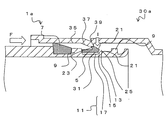
図7bに示すように、この状態から雌型嵌合部30aへ雄型嵌合部1aを押し込むと(図中矢印F)、雌型嵌合部30aの斜面部37によって爪部23が押圧され、リング部材5の内面と小径部17との間のクリアランスによって、リング部材5の全体を縮径することができる(図中矢印I)。すなわち、リング部材5の全体を、雄型嵌合部1aの小径部17に収納することができる。
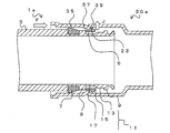
図8aに示すように、この状態から雌型嵌合部30aへ雄型嵌合部1aをさらに押し込むと(図中矢印F)、爪部23の端部が雌型嵌合部30aの斜面部37を通り抜ける。この際、弾性変形していたリング部材5は、斜面部37からの押圧が解放され、元の径に復元して拡径する(図中矢印J)。これにより、爪部23が、雌型嵌合部30aの斜面部37の基部側に形成されたリング嵌合部39に収納される。
図8bは、このようにして得られる、雄型嵌合部1aと雌型嵌合部30aとが接続された接続構造10を示す図である。この状態では、爪部23の先端が、雌型嵌合部30aのリング嵌合部39と嵌合する。このため、雌型嵌合部30aを引き抜こうとしても(図中矢印K)、リング部材5は、係止壁9によって移動が規制され、雌型嵌合部30aから雄型嵌合部1aが引き抜かれることがない。
特に、リング部材5の通常時の内径は、雄型嵌合部1aの大径部13と略一致する。このため、リング部材5が大径部13の位置にある場合には、リング部材5の内面と大径部13の外面との間には十分なクリアランスが生じない。このため、リング部材5が縮径することが抑制され、爪部23とリング嵌合部39との嵌合が外れることを抑制することができる。
なお、前述したように、リング部材5は、大径部13に位置する際には、リング部材5の内面と大径部13の外面とのクリアランスが小さいため、縮径が規制され、小径部17に移動することで、リング部材5の内面と小径部17の外面とのクリアランスが大きいため縮径が可能な状態となる。しかし、これに加えて、さらに他の構造によってリング部材5の縮径を規制してもよい。
図9aは、雄型嵌合部1aに縮径制限リブ33を形成した状態を示す図である。縮径制限リブ33は、係止壁9で挟まれた領域に形成され、大径部13から斜面部15を挟んで小径部17に連続するように、管軸方向に所定寸法にて形成される。縮径制限リブ33の外面は、大径部13の外径よりも大径となり、例えば、係止壁9と同等の高さのリブである。
縮径制限リブ33は、大径部13から小径部17に行くにつれて、徐々に幅(周方向長さ)が狭くなる。すなわち、大径部13における縮径制限リブ33の幅よりも小径部17における縮径制限リブ33の幅が狭い。縮径制限リブ33には、リング部材5の切断部19が位置し、縮径制限リブ33が切断部19へ嵌り込む。なお、大径部13における縮径制限リブ33の幅に対して、小径部17における縮径制限リブ33の幅が狭くなれば、縮径制限リブ33の幅は徐々に変化するのではなくてもよい。例えば、大径部13と小径部17(斜面部15)との境界部近傍で、縮径制限リブ33の幅が段差となるように変化してもよい。
図9aに示すように、リング部材5が大径部13に位置する際には、縮径制限リブ33の幅は、切断部19の幅(周方向長さ)と略同等である。したがって、リング部材5が縮径しようとしても、切断部19におけるリング部材5の周方向端面が縮径制限リブ33と接触して、それ以上の縮径が規制される。
一方、図9bに示すように、リング部材5が小径部17に位置する際には、縮径制限リブ33の幅は、切断部19の幅(周方向長さ)よりも十分に狭い。このため、切断部19におけるリング部材5の周方向端面と縮径制限リブ33との間にクリアランスが生じる。このため、リング部材5が縮径可能となる。
ここで、リング部材5の最大厚み(平坦部31から爪部23の先端までの高さ)は、雄型嵌合部1aを雌型嵌合部30aに挿入した際に、雄型嵌合部1aの小径部17と雌型嵌合部の斜面部37の最小内径部との径方向クリアランス(雄型嵌合部1aの小径部17の外径と、雌型嵌合部の斜面部37の最小内径との差によるクリアランス)よりも小さい。したがって、リング部材5は小径部17の位置において縮径可能となり、この際、雌型嵌合部の斜面部37の最小内径部が、リング部材5を通過した時に、リング部材5が拡径して、雌型嵌合部30aの斜面部37を爪部23が乗り越えることができる。
また、リング部材5の最大厚み(平坦部31から爪部23の先端までの高さ)は、雄型嵌合部1aを雌型嵌合部30aに挿入した際に、雄型嵌合部1aの大径部13と雌型嵌合部30aのリング嵌合部39による拡径部の径方向クリアランス(雄型嵌合部1aの大径部13の外径と、リング嵌合部39による拡径部の内径との差によるクリアランス)よりも小さい。このため、リング部材5は大径部13の位置において縮径が規制されるともに、雌型嵌合部30aのリング嵌合部39と嵌合する。
このように、リング部材5は、その位置によって、大径部13の位置では縮径が規制され、小径部17の位置では縮径が可能となることで、接続が容易であるとともに抜けを防止することができる。
なお、リング部材5が、小径部17から大径部13へスムーズに移動することができるように、リング部材5のテーパ部25のテーパ角度(雄型嵌合部1aの管軸方向断面において、平坦部31の延長線とテーパ部25とのなす角度)は、雄型嵌合部1aの斜面部15のテーパ角度(雄型嵌合部1aの管軸方向断面において、小径部17の延長線と斜面部15とのなす角度)と同一またはリング部材5のテーパ部25のテーパ角度の方を大きくすることが望ましい。
なお、この状態において、止水部材7の外周面は、雌型嵌合部30aの筒状部35の内面と密着する。すなわち、止水部材7で、雄型嵌合部1aと雌型嵌合部30aの隙間を埋めることができる。このため、接続構造10に、外部から水分が浸入することを防止することができる。
また、止水部材7が、リング部材5よりも基部側に配置されるため、雄型嵌合部1aを雌型嵌合部30aへ押し込む際に、雌型嵌合部30aが止水部材7と接触するまでは、止水部材7による抵抗を受けることがない。このため、雄型嵌合部1aの雌型嵌合部30aへの押込み抵抗を小さくすることができる。
なお、雄型嵌合部1aと雌型嵌合部30aのそれぞれの形状を、十分な強度を有する材質で作成し、両者を嵌合させた状態で引張試験機に取付けて、引張試験機で荷重を負荷して、引抜き荷重を求めた。その結果、引き抜き荷重は、100kgを満足した。したがって、継手部の引き抜き力は十分な引き抜き力を有することが確認できた。
次に、雄型嵌合部1aを有する電線管について説明する。図10は、電線管40aを示す図である。電線管40aは、両端に嵌合構造を有し、管体3aの一方の端部に形成された雄型嵌合部1aと、管体3aの他方の端部に形成され、雄型嵌合部1aと嵌合可能な形状を有する雌型嵌合部30aとを具備する。なお、以下の説明では、縮径制限リブ33を設けた例について説明するが、縮径制限リブ33は無くてもよい。
電線管40aは、雄型嵌合部1aと雌型嵌合部30aの間において、管体3aの外周面に、連続した所定ピッチの螺旋状の波形状41が形成される。このような電線管40aを用いれば、複数本の電線管40aを互いに接続して使用することができる。例えば、電線管40aの接続方法としては、前述した雄型嵌合部1aと雌型嵌合部30aとの接続方法と同様である。すなわち、複数の電線管40aを具備し、一の電線管40aの雄型嵌合部1aを、他の電線管40aの雌型嵌合部30aを挿入するだけで、一の電線管40aの雄型嵌合部1aと、他の電線管40aの雌型嵌合部30aとが嵌合して接続される電線管の接続構造を得ることができる。そのため、電線管40a同士の接続に関して、螺旋状の継手などのねじ込みを必要としないので、工事が容易である。
なお、管体の形状はこれには限られない。図11aは、電線管40bを示す図である。また、図11bは、図11aのN部近傍の拡大断面図であり、図12aは、図11aのL-L線断面図、図12bは、図11aのM-M線断面図である。電線管40bは、電線管40aの管体3aに代えて、管体3bが適用される点で異なる。
図12a、図12bに示すように、電線管40bでは、雄型嵌合部1aと雌型嵌合部30aの間において、管体3bの外周面に山部43(大径部位)と谷部45(小径部位)とが交互に形成される。山部43は、断面が略正方形状であり、谷部45は、断面が円形状である。山部43の径(1辺の長さ)は、谷部45における外径よりも大きい。
このように、略正方形の山部43を谷部45に対して交互に設けることで、電線管40bを積み上げた際に、電線管40bを安定して配列することができる。なお、雌型嵌合部30aの最大外径は、山部43の径(1辺の長さ)よりも小さい。したがって、雌型嵌合部30a側の端部から見た際に、雌型嵌合部30aは、山部43の外周にはみ出すことがない。したがって、山部43同士を接触させて電線管40bを積み上げた際に、雌型嵌合部30aが、隣り合う電線管40bと干渉することがない。
また、図11bに示すように、管体3bの管軸方向に対する谷部45の略中央部に、一対の突起部47が形成される。また、管体3bの管軸方向断面において、突起部47の間には、平坦部49が形成される。このように、突起部47の間に溝形状を形成することで、溝に沿って刃物を使用することができ、管体3bの切断が容易である。また、切断位置がずれにくいため、管体3bを精度よく切断することができる。もちろん、特に図示しないが、谷部45に一対の突起部を設けずに、谷部45を断面円形状の直管とすることができる。
また、図13は、電線管40cを示す図である。電線管40cは、電線管40aの管体3aに代えて、管体3cが適用される点で異なる。管体3cは、管体3bと同様に、略正方形の山部43と、円形の谷部45とが交互に形成される。
管体3cの谷部45は、山部43の長さよりも十分に長い。また、管体3cの管軸方向断面において、谷部45は波形に形成される。なお、谷部45における波形の最大外径は、山部43の外径よりも小さい。電線管40cも、電線管40bと同様に、略正方形の山部43を設けることで、電線管40cを積み上げた際に、電線管40cを安定して配列することができる。
次に、前述した電線管と接続可能なベルブロックについて説明する。図14は、ベルブロック50の断面図である。ベルブロック50は、電線管40b等と接続可能であり、雌型嵌合部30aと同一構造を有する。すなわち、ベルブロック50の一端側の内面には、一方の先端側(開口側)から、順に、筒状部35と、筒状部35から徐々に縮径する斜面部37と、斜面部37の最小内径部から拡径したリング嵌合部39を有する。また、ベルブロック50の他方の端部は、開口端に向かって徐々に内径が広がるベルマウス53が形成される。
ベルブロック50は、雌型嵌合部30a側に電線管40b等の雄型嵌合部1aが挿入されて接続される。また、ベルマウス53からは、内部に電線等を挿通することができる。
図15は、複数のベルブロック50を有するハンドホール55を示す図である。ハンドホール55は、例えばコンクリート製の箱型であり、ベルブロック50がコンクリートに埋め込まれる。すなわち、コンクリート製のハンドホール55の側面には、ベルブロック50によって複数の貫通孔が形成される。なお、ハンドホール55に接続孔を形成し、接続孔に挿入したベルブロック50の外周をモルタルやエポキシパテなどで固めて、ハンドホール55にベルブロック50を固定してもよい。
図16は、ハンドホール55に設けられたベルブロック50と電線管40bとの接続構造10aを示す断面図である。なお、電線管40bに代えて、他の電線管を適用することもできる。前述したように、ハンドホール55には、複数のベルブロック50が配置される。電線管40bは、ベルブロック50の一部またはすべてと接続される。すなわち、接続構造10aは、ベルブロック50を有するハンドホール55と、電線管40bを具備し、雌型嵌合部30aと同一構造を有するベルブロック50と、電線管40bの雄型嵌合部1aとが接続されて構成される。
なお、電線管40bとベルブロック50との接続方法としては、前述した電線管同士の接続方法と同様である。すなわち、一方の電線管40bの雌型嵌合部30aに代えて、ベルブロック50の雌型嵌合部30aに対して、前述した方法と同様の手順で、雄型嵌合部1aを挿入すればよい。このようにすることで、電線管の雌型嵌合部30aと同一構造のベルブロック50を有するハンドホール55と、電線管40bの雄型嵌合部1aとが接続される電線管の接続構造10aを得ることができる。
ここで、前述したように、電線管40bは、山部43が角型の電線管であるため、電線管40bを多条多段に積み重ねることができ、コンパクトに配置することができる。このため、電線管40bの埋設時の土砂の掘り起し量を少なくすることが可能になると共に、一括で埋め戻すことができるため工事の負荷が減少する。この結果、工期の短縮、工事コストの削減を達成することができる。
例えば、本発明の電線管40bは、雄型嵌合部1aを雌型嵌合部30aに挿入するだけで、電線管40b同士を接続することができる。したがって、螺旋溝を有する管継手によって接続する電線管と異なり、例えば、定尺の電線管40b同士を相互に直接接続することができる。
なお、ハンドホール55と電線管40bの接続は、電線管40bの雄型嵌合部1aで接続する他、雌型嵌合部30aと嵌合する嵌合部を有するベルマウスを有していても良い。
図17は、ベルブロック50aを示す図である。なお、本発明においては、前述した各種の電線管と接続が可能であり、少なくとも一方に雄型嵌合部1aまたは雌型嵌合部30aと同一の構造を具備する部材を、管継手と称する場合がある。
ベルブロック50aは、ベルブロック50と異なり、雄型嵌合部1aを具備する。すなわち、ベルブロック50aは、一方の端部が雄型嵌合部1aと同一構造を有し、他方の端部がベルマウス53である。この場合には、雄型嵌合部1aをハンドホール55の外面から突出させることで、電線管の雌型嵌合部30aと接続が可能である。
また、図18aは、管継手60aを示す図である。管継手60aは、両方の端部が雄型嵌合部1aと同一構造を有する。管継手60aを用いることで、端部に雌型嵌合部30aを具備する電線管同士を接続することができる。例えば、両端が雌型嵌合部30aの電線管同士を接続することもできる。また、電線管の雌型嵌合部30aを雄型嵌合部1aに変換することもできる。
ここで、電線管40bを繰り返し接続して電線管40bの管路を形成する場合には、例えば、向かい合う2つのハンドホール55に、雌型嵌合部30aの形状を有するベルブロック50を配置する。次に、一方のハンドホール55のベルブロック50に、雄型嵌合部1aを挿入することで、雄型嵌合部1aをハンドホール55に固定する。嵌合が終わった電線管40bの他端の雌型嵌合部30aには、隣り合う、次の電線管40bの雄型嵌合部1aを接続することで管路を延線していく。
また、この作業と並行して、向かい合うもう一方のハンドホール55のベルブロック50にも、電線管40bの雄型嵌合部1aを挿入し接続する。嵌合が終わった電線管40bの他端の雌型嵌合部30aに、隣り合う、次の電線管40bの雄型嵌合部1aを接続することで管路を延線していく。この作業を両側のハンドホール55から繰り返すと、電線管40bがラップする部分が生じる。このため、電線管40bの長さ調整が必要となる。電線管40bの長さ調整は、両側から延線してきた電線管40bの谷部45を切断して接続することで行われる。
ところで、このように電線管40bを接続していくと、一端が雌型嵌合部30aで、もう一端が谷部45で切断した管が端材として出てくることになる。この端材は捨てずに電線管路を形成する管として用いる方が経済的である。端材を用いるためには、一端が雄型嵌合部1aでもう一端も雄型嵌合部1aの形状をした管継手60aを用いることが有効である。
端材の雌型嵌合部30aに両端が雄型嵌合部1aの継手を接続すると、片端が雄型嵌合部1a、もう片端が谷部45で切断した管ができる。片端を雄型嵌合部1aとすることで、向かい合う2つのハンドホール55に形成された雌型形状を有するベルブロック50の一方に接続することができる。また、他方のハンドホール55から延線してきた管と長さ調整をすることで、ハンドホール間を繋ぐ電線管路が形成される。ここで、このようにして、片端が谷部45である切断した管同士が対向した場合には、対向した谷部45同士を接続する専用の継手を用いて接続することができる。
ここで、前述したように、電線管40bは、谷部45に対向する2つの突起部47が設けられ、突起部47の間に溝形状が形成される。このような突起部47が存在せず、溝形状が形成されていない電線管を切断する場合には、切断される部位の目印がなく、切断の案内溝が存在しないことから、切断の際に、刃物が滑って斜めに電線管が切断される場合がある。特に、雨天の場合などには電線管が濡れるため、切断時に電線管や刃物が滑りやすくなるため、電線管が所定位置で切断されず、また、斜めに切断されやすい。このように、斜めに切断された電線管同士を接続しようとすると、管継手内の電線管の端部同士の位置調整がうまくできずに、管継手での接続ができないことがある。このような場合には、切断した電線管が無駄になる。
これに対し、電線管40bは、谷部45に対向する2つの突起部47を設け、突起部47の間に溝形状を形成することで、溝に沿って刃物を使用することができる。このため、切断位置を把握しやすく、また、刃物が滑ることを抑制することができる。このため、切断位置のずれや斜めに切断されることがない。
また、図18bは、管継手60bを示す図である。管継手60bは、一方の端部が雄型嵌合部1aと同一構造を有し、他方の端部が雌型嵌合部30aと同一構造を有する。管継手60bを用いることで、少なくとも一方の端部に雄型嵌合部1aを具備する電線管と、少なくとも一方の端部に雌型嵌合部30aを具備する電線管同士を接続することができる。
また、図19aは、管継手60cを示す図である。管継手60cは、両方の端部が雌型嵌合部30aと同一構造を有する。管継手60cを用いることで、一方の端部に雄型嵌合部1aを具備する電線管同士を接続することができる。例えば、両端が雄型嵌合部1aの電線管同士を接続することもできる。また、電線管の雄型嵌合部1aを雌型嵌合部30aに変換することもできる。
また、図19bは、管継手60dを示す図である。管継手60dは、一方の端部が雌型嵌合部30aと同一構造を有し、他方の端部が管体の外表面(および内表面)に連続した螺旋状の波形状61を有する。管継手60dを用いることで、少なくとも一方の端部に雄型嵌合部1aを具備する電線管と、外面に螺旋波付形状を有する電線管を接続することができる。このように、図19bに示すような管継手を用いれば、本発明のような角型断面形状を有する電線管と外面に螺旋波付形状を有する電線管の異なる断面形状を有する電線管同士を接続する異種管継手が実現できる。
以上説明したように、本実施形態によれば、電線管等の接続部に用いられるリング部材5が雄型嵌合部1aの外面に配置されるため、リング部材5を容易に視認することができる。
また、リング部材5が、リング部材配置部11内でスライド移動可能であるため、雄型嵌合部1aを雌型嵌合部30aへ押し込む際には、リング部材5の端部近傍を大径部13から小径部17へ移動させることができる。このため、断面C字状のリング部材5を容易に縮径することができる。
このように、リング部材5の全体が縮径するため、引き抜き力がかかるリング部材5の爪部23の肉厚を大きくしても、リング部材5を容易に縮径することができる。この結果、雄型嵌合部1aと雌型嵌合部30aの接続が容易であるとともに、接続状態から雄型嵌合部1aの抜けを確実に防止することができる。
また、接続後に、雄型嵌合部1aが引き抜かれる方向に力が付与されると、リング部材5が大径部13の位置へ移動する。このため、リング部材5の縮径を抑制することができる。また、このような効果は、縮径制限リブ33によっても得ることができる。
また、止水部材7が、リング部材5よりも基部側に配置されるため、雄型嵌合部1aを雌型嵌合部30aに挿入する際、止水部材7による挿入抵抗を受けにくくすることができる。また、仮に止水部材7に滑剤を塗布したとしても、滑剤がリング部材5に付着することがない。
また、電線管40a等は、一方の端部に雄型嵌合部1aを有し、他方の端部に雌型嵌合部30aを有するため、複数の電線管40a同士を接続するのが容易である。
特に、電線管40bは、管体の外周面に略正方形状の山部43と、円形状の谷部45が交互に形成されるため、複数の電線管40bを積層する際に、安定して電線管40bを積み上げることができる。また、電線管40bは、管体の管軸方向に対する谷部45の略中央部に、一対の突起部47が形成され、突起部47の間に溝形状が形成されるため、当該部位で、容易に電線管40aを切断することができる。そのため、切断された管の切断位置の精度を高く保ち、高精度の電線管の接続構造や電線管の管路を構築することが可能になる。
また、少なくとも一方の端部に雄型嵌合部1aまたは雌型嵌合部30aを具備する管継手を用いることで、種々の電線管を容易に接続することができる。同様に、一方の端部に雄型嵌合部1aまたは雌型嵌合部30aを具備するベルブロックを用いることで、ベルブロックと電線管とを容易に接続することができる。
以上、添付図を参照しながら、本発明の実施の形態を説明したが、本発明の技術的範囲は、前述した実施の形態に左右されない。当業者であれば、特許請求の範囲に記載された技術的思想の範疇内において各種の変更例または修正例に想到し得ることは明らかであり、それらについても当然に本発明の技術的範囲に属するものと了解される。
1a………雄型嵌合部
3、3a、3b、3c………管体
5………リング部材
7………止水部材
9………係止壁
10、10a………接続構造
11………リング部材配置部
13………大径部
15………斜面部
17………小径部
19………切断部
21………テーパ部
23………爪部
25………テーパ部
27………止水部材収容部
29………クリアランス
30a………雌型嵌合部
31………平坦部
35………筒状部
37………斜面部
39………リング嵌合部
40a、40b、40c………電線管
41……波形状
43……山部
45……谷部
47……突起部
49……平坦部
50、50a……ベルブロック
53……ベルマウス
55……ハンドホール
60a、60b、60c、60d……管継手
61……波形状
3、3a、3b、3c………管体
5………リング部材
7………止水部材
9………係止壁
10、10a………接続構造
11………リング部材配置部
13………大径部
15………斜面部
17………小径部
19………切断部
21………テーパ部
23………爪部
25………テーパ部
27………止水部材収容部
29………クリアランス
30a………雌型嵌合部
31………平坦部
35………筒状部
37………斜面部
39………リング嵌合部
40a、40b、40c………電線管
41……波形状
43……山部
45……谷部
47……突起部
49……平坦部
50、50a……ベルブロック
53……ベルマウス
55……ハンドホール
60a、60b、60c、60d……管継手
61……波形状
Claims (27)
- 管体の端部近傍の外周部に形成される雄型嵌合部を有する電線管であって、
前記雄型嵌合部は、管軸方向に離間して配置される一対の係止壁と、
前記係止壁で挟まれた領域に配置されるリング部材と、
を具備し、
前記リング部材は、円周方向の一部が切断された略C字状であり、
前記リング部材の管軸方向の断面において、前記リング部材は、内面が平坦であり、外面に爪部を有し、外面及び内面の両者に前記リング部材の一方の端部に向かって先細りとなるテーパ部を有し、
前記リング部材は、前記テーパ部による先細り側が前記管体の先端側に位置するように配置され、
前記係止壁で挟まれた領域の、前記管体の先端側には大径部が形成され、前記係止壁で挟まれた領域の前記管体の基部側には小径部が形成され、前記大径部と前記小径部との間に斜面部が形成され、
前記リング部材の前記テーパ部を除く管軸方向の長さは、前記小径部の長さと等しいか、前記小径部の長さよりも短く、
前記リング部材は、少なくとも一方の前記係止壁との間にクリアランスを有し、前記リング部材が、前記大径部または前記小径部のいずれかの位置にスライド可能であることを特徴とする電線管。 - 前記雄型嵌合部の基部側の前記係止壁よりもさらに基部側に、止水部材が設けられることを特徴とする請求項1記載の電線管。
- 前記係止壁で挟まれた領域には、前記大径部から前記斜面部を挟んで前記小径部に連続し、前記大径部の外径より大径の縮径制限リブが、管軸方向に所定寸法にて形成され、前記縮径制限リブに前記リング部材の切断部が嵌ることを特徴とする請求項1記載の電線管。
- 両端に嵌合構造を有する電線管であって、
管体と、
前記管体の一方の端部に形成された雄型嵌合部と、
前記管体の他方の端部に形成され、前記雄型嵌合部と嵌合可能な形状を有する雌型嵌合部と、
を具備し、
前記雄型嵌合部は、前記管体の外周部に形成され、管軸方向に離間して配置される一対の係止壁と、
前記係止壁で挟まれた領域に配置されるリング部材と、
を具備し、
前記リング部材は、円周方向の一部が切断された略C字状であり、
前記リング部材の管軸方向の断面において、前記リング部材は、内面が平坦であり、外面に爪部を有し、外面及び内面の両者に前記リング部材の一方の端部に向かって先細りとなるテーパ部を有し、
前記リング部材は、前記テーパ部による先細り側が前記管体の先端側に位置するように配置され、
前記係止壁で挟まれた領域の、前記管体の先端側には大径部が形成され、前記係止壁で挟まれた領域の前記管体の基部側には小径部が形成され、前記大径部と前記小径部との間に斜面部が形成され、
前記リング部材の管軸方向の長さは、前記小径部の長さよりも短く、
前記リング部材は、少なくとも一方の前記係止壁との間にクリアランスを有し、前記リング部材が、前記大径部または前記小径部のいずれかの位置にスライド可能であり、
前記雌型嵌合部は、前記管体の内周部に形成され、先端側から、筒状部と、前記筒状部から徐々に縮径する斜面部と、前記斜面部の最小内径部から拡径したリング嵌合部と、を具備することを特徴とする電線管。 - 前記係止壁で挟まれた領域には、前記大径部から前記斜面部を挟んで前記小径部に連続し、前記大径部の外径より大径の縮径制限リブが、管軸方向に前記大径部における前記縮径制限リブの幅よりも前記小径部における前記縮径制限リブの幅が狭く形成され、前記縮径制限リブに前記リング部材の切断部が嵌ることを特徴とする請求項4に記載の電線管。
- 前記雄型嵌合部の基部側の前記係止壁よりもさらに基部側に、止水部材が設けられることを特徴とする請求項4記載の電線管。
- 前記雄型嵌合部と前記雌型嵌合部の間において、前記管体の外周面に連続した所定ピッチの螺旋状の波形状が形成されることを特徴とする請求項4記載の電線管。
- 前記雄型嵌合部と前記雌型嵌合部の間において、前記管体の外周面に略正方形状の山部としての大径部位と、円形状の谷部として小径部位が交互に形成されることを特徴とする請求項4記載の電線管。
- 前記管体の管軸方向に対する前記谷部としての小径部位の略中央部に、一対の突起部が形成され、前記管体の管軸方向断面において、前記突起部の間に平坦部が形成されることを特徴とする請求項8記載の電線管。
- 前記管体の管軸方向断面において、前記谷部としての小径部位が波形に形成されることを特徴とする請求項8記載の電線管。
- 前記止水部材は、前記雄型嵌合部の基部側の前記係止壁よりもさらに基部側に形成された止水部材収容部に配置されることを特徴とする請求項6記載の電線管。
- 前記リング部材は、ABS樹脂、PP樹脂、硬質塩化ビニルまたはこれらのいずれかとPC樹脂の混合樹脂またはポリマーアロイのいずれかであることを特徴とする請求項6記載の電線管。
- 前記止水部材は、ゴム製または水膨張部材のいずれかであることを特徴とする請求項6記載の電線管。
- 請求項4記載の電線管の接続構造であって、
複数の前記電線管を用い、一の前記電線管の前記雄型嵌合部と、他の前記電線管の前記雌型嵌合部とが嵌合して接続され、
前記リング部材の最大厚みは、前記雄型嵌合部の前記小径部と前記雌型嵌合部の前記斜面部の最小内径部との径方向クリアランスおよび前記雄型嵌合部の前記大径部と前記雌型嵌合部のリング嵌合部の径方向クリアランスよりも小さいことを特徴とする電線管の接続構造。 - 請求項4記載の電線管の接続構造であって、
ベルブロックを有するハンドホールと、前記電線管を用い、
前記雌型嵌合部と同一構造を有する前記ベルブロックと、前記電線管の前記雄型嵌合部とが接続されることを特徴とする電線管の接続構造。 - 前記ハンドホールは、複数の前記ベルブロックを有し、
前記電線管は、前記ベルブロックの一部またはすべてと接続されることを特徴とする請求項15記載の電線管の接続構造。 - 請求項4記載の電線管と接続可能であり、前記雌型嵌合部と同一構造を有することを特徴とするベルブロック。
- 請求項4記載の電線管同士の接続方法であって、
前記雄型嵌合部の先端を前記雌型嵌合部に挿入する工程と、
前記雌型嵌合部の前記斜面部に、前記係止壁で挟まれた領域に配置された前記リング部材の外周の前記テーパ部を接触させて、前記リング部材を前記雄型嵌合部の前記小径部までスライド移動させて縮径し、前記リング部材を前記雄型嵌合部の前記小径部に収納する工程と、
前記爪部の端部が前記雌型嵌合部の前記斜面部を通り抜けることで、前記爪部が、前記雌型嵌合部の前記斜面部の基部側に形成された前記リング嵌合部に収納されることを特徴とする電線管同士の接続方法。 - 請求項11記載の電線管とベルブロックとの接続方法であって、
前記ベルブロックは、前記電線管の前記雌型嵌合部と同一の構造を有し、
前記雄型嵌合部の先端を前記ベルブロックに挿入する工程と、
前記ベルブロックの前記斜面部に、前記係止壁で挟まれた領域に配置された前記リング部材の外周の前記テーパ部を接触させて、前記リング部材を前記雄型嵌合部の前記小径部までスライド移動させて縮径し、前記リング部材を前記雄型嵌合部の前記小径部に収納する工程と、
前記爪部の端部が前記ベルブロックの前記斜面部を通り抜けることで、前記爪部が、前記ベルブロックの前記斜面部の基部側に形成された前記リング嵌合部に収納されることを特徴とする電線管とベルブロックの接続方法。 - 請求項4記載の電線管と接続可能であり、少なくとも一方の端部が前記雄型嵌合部と同一構造を有することを特徴とする管継手。
- 両方の端部が前記雄型嵌合部と同一構造を有することを特徴とする請求項20記載の管継手。
- 一方の端部が前記雄型嵌合部と同一構造を有し、他方の端部がベルマウスであることを特徴とする請求項20記載の管継手。
- 一方の端部が前記雄型嵌合部と同一構造を有し、他方の端部が前記雌型嵌合部と同一構造を有することを特徴とする請求項20記載の管継手。
- 請求項4記載の電線管と接続可能であり、少なくとも一方の端部が前記雌型嵌合部と同一構造を有することを特徴とする管継手。
- 一方の端部が前記雌型嵌合部と同一構造を有し、他方の端部がベルマウスであることを特徴とする請求項24記載の管継手。
- 一方の端部が前記雌型嵌合部と同一構造を有し、他方の端部が前記管体の外表面に連続した螺旋状の波形状を有することを特徴とする請求項24記載の管継手。
- 電線管の接続部に用いられるリング部材であって、
前記リング部材は、
円周方向の一部が切断された略C字状であり、
前記リング部材の管軸方向の断面において、内面が平坦であり、外面に爪部を有し、外面及び内面の両者に前記リング部材の一方の端部に向かって先細りとなるテーパ部を有することを特徴とするリング部材。
Applications Claiming Priority (2)
| Application Number | Priority Date | Filing Date | Title |
|---|---|---|---|
| JP2017031722A JP6499214B2 (ja) | 2017-02-23 | 2017-02-23 | 電線管、電線管の接続構造、ベルブロック、電線管同士の接続方法、電線管とベルブロックの接続方法、管継手、リング部材 |
| JP2017-031722 | 2017-02-23 |
Publications (1)
| Publication Number | Publication Date |
|---|---|
| WO2018155359A1 true WO2018155359A1 (ja) | 2018-08-30 |
Family
ID=63253780
Family Applications (1)
| Application Number | Title | Priority Date | Filing Date |
|---|---|---|---|
| PCT/JP2018/005666 Ceased WO2018155359A1 (ja) | 2017-02-23 | 2018-02-19 | 電線管、電線管の接続構造、ベルブロック、電線管同士の接続方法、電線管とベルブロックの接続方法、管継手、リング部材 |
Country Status (2)
| Country | Link |
|---|---|
| JP (1) | JP6499214B2 (ja) |
| WO (1) | WO2018155359A1 (ja) |
Cited By (1)
| Publication number | Priority date | Publication date | Assignee | Title |
|---|---|---|---|---|
| JP2021158911A (ja) * | 2020-03-27 | 2021-10-07 | 古河電気工業株式会社 | 二重壁角型電線管の管路、角形電線管の管路及び二重壁角型電線管の管路の長さ調整方法 |
Families Citing this family (4)
| Publication number | Priority date | Publication date | Assignee | Title |
|---|---|---|---|---|
| JP2019126254A (ja) * | 2019-03-06 | 2019-07-25 | 古河電気工業株式会社 | 電線管、電線管の接続構造、ベルブロック、電線管同士の接続方法、電線管とベルブロックの接続方法、管継手、リング部材 |
| KR200493539Y1 (ko) * | 2019-10-23 | 2021-04-19 | (주)케이제이 | 샤워 헤드용 수전연결구 |
| KR102394027B1 (ko) * | 2020-06-23 | 2022-05-06 | 한국전력공사 | 저압 접속함용 체결 장치 |
| US11670924B2 (en) | 2021-10-22 | 2023-06-06 | Abb Schweiz Ag | Fitting connections for corrosion resistant electrical conduits |
Citations (4)
| Publication number | Priority date | Publication date | Assignee | Title |
|---|---|---|---|---|
| JPS59173418U (ja) * | 1983-05-04 | 1984-11-20 | 未来工業株式会社 | 電線管用連結装置 |
| JP2000227189A (ja) * | 1998-12-04 | 2000-08-15 | Shinwa Sangyo Co Ltd | フレキシブルチューブ用継手 |
| JP2006125521A (ja) * | 2004-10-28 | 2006-05-18 | Sekisui Chem Co Ltd | 差し込み継手 |
| JP2016008630A (ja) * | 2014-06-23 | 2016-01-18 | 株式会社イノアック住環境 | 継手付きフレキシブル管 |
-
2017
- 2017-02-23 JP JP2017031722A patent/JP6499214B2/ja active Active
-
2018
- 2018-02-19 WO PCT/JP2018/005666 patent/WO2018155359A1/ja not_active Ceased
Patent Citations (4)
| Publication number | Priority date | Publication date | Assignee | Title |
|---|---|---|---|---|
| JPS59173418U (ja) * | 1983-05-04 | 1984-11-20 | 未来工業株式会社 | 電線管用連結装置 |
| JP2000227189A (ja) * | 1998-12-04 | 2000-08-15 | Shinwa Sangyo Co Ltd | フレキシブルチューブ用継手 |
| JP2006125521A (ja) * | 2004-10-28 | 2006-05-18 | Sekisui Chem Co Ltd | 差し込み継手 |
| JP2016008630A (ja) * | 2014-06-23 | 2016-01-18 | 株式会社イノアック住環境 | 継手付きフレキシブル管 |
Cited By (2)
| Publication number | Priority date | Publication date | Assignee | Title |
|---|---|---|---|---|
| JP2021158911A (ja) * | 2020-03-27 | 2021-10-07 | 古河電気工業株式会社 | 二重壁角型電線管の管路、角形電線管の管路及び二重壁角型電線管の管路の長さ調整方法 |
| JP7623162B2 (ja) | 2020-03-27 | 2025-01-28 | 古河電気工業株式会社 | 二重壁角型電線管とハンドホールとの接続構造 |
Also Published As
| Publication number | Publication date |
|---|---|
| JP2018135972A (ja) | 2018-08-30 |
| JP6499214B2 (ja) | 2019-04-10 |
Similar Documents
| Publication | Publication Date | Title |
|---|---|---|
| JP6391903B1 (ja) | 電線管、電線管の接続構造、ベルブロック、電線管同士の接続方法、電線管とベルブロックの接続方法、管継手、およびリング部材 | |
| JP6469938B2 (ja) | 電線管、電線管の接続構造、ベルブロック、電線管同士の接続方法、電線管とベルブロックの接続方法、管継手、リング部材 | |
| JP6499214B2 (ja) | 電線管、電線管の接続構造、ベルブロック、電線管同士の接続方法、電線管とベルブロックの接続方法、管継手、リング部材 | |
| US5722702A (en) | Plastic pipe compression coupler | |
| KR100789637B1 (ko) | 파이프 커플링 | |
| US8240715B2 (en) | Connection structure of tubular connection member and joint member | |
| CN104272003A (zh) | 管接头 | |
| JP7534750B2 (ja) | 管更生部材 | |
| US11101626B2 (en) | Corrugated tube that can be folded open and wiring harness | |
| JP5572436B2 (ja) | 可撓性合成樹脂管 | |
| JP2019126254A (ja) | 電線管、電線管の接続構造、ベルブロック、電線管同士の接続方法、電線管とベルブロックの接続方法、管継手、リング部材 | |
| JP6330081B1 (ja) | 角型電線管用管継手、角型電線管と角型電線管用管継手の接続構造 | |
| JP6734219B2 (ja) | 角型電線管、角型電線管の接続構造、管路構造の長さ調整方法、角型電線管の切断方法 | |
| AU2018243151A1 (en) | Pipe joint, rectangular electric wire pipe, and pipe joint connection structure | |
| JP6734319B2 (ja) | 角型電線管用管継手、π型固定部材、π型固定部材の継手本体への固定方法、角型電線管の角型電線管用管継手への固定方法 | |
| JP2021142694A (ja) | 螺旋管用帯状部材及び螺旋管 | |
| KR20030007017A (ko) | 이음용 패킹 및 이것을 이용한 관의 접속 구조 | |
| JP7372631B2 (ja) | ライニング部材 | |
| JP7290252B2 (ja) | 管更生部材 | |
| JP2023140339A (ja) | 継手部品、継手部品と可撓電線管との接続構造、管継手部材と可撓電線管との接続構造、継手部品と管継手部材と可撓電線管との接続構造、配管システム、継手部品の製造方法 | |
| JP6373542B1 (ja) | 電線管用リング部材、雄型嵌合部のリング部材取り付け部への電線管用リング部材の取付け構造、リング部材の使用方法および電線管への電線管用リング部材の取り付け方法 | |
| JP5036278B2 (ja) | 波付管接続装置 | |
| JP2002098268A (ja) | 波付合成樹脂管およびリング |
Legal Events
| Date | Code | Title | Description |
|---|---|---|---|
| 121 | Ep: the epo has been informed by wipo that ep was designated in this application |
Ref document number: 18757054 Country of ref document: EP Kind code of ref document: A1 |
|
| NENP | Non-entry into the national phase |
Ref country code: DE |
|
| 122 | Ep: pct application non-entry in european phase |
Ref document number: 18757054 Country of ref document: EP Kind code of ref document: A1 |