WO2018155182A1 - 蓄電ユニット - Google Patents
蓄電ユニット Download PDFInfo
- Publication number
- WO2018155182A1 WO2018155182A1 PCT/JP2018/004150 JP2018004150W WO2018155182A1 WO 2018155182 A1 WO2018155182 A1 WO 2018155182A1 JP 2018004150 W JP2018004150 W JP 2018004150W WO 2018155182 A1 WO2018155182 A1 WO 2018155182A1
- Authority
- WO
- WIPO (PCT)
- Prior art keywords
- bracket
- holder
- power storage
- metal case
- storage unit
- Prior art date
- Legal status (The legal status is an assumption and is not a legal conclusion. Google has not performed a legal analysis and makes no representation as to the accuracy of the status listed.)
- Ceased
Links
Images





Classifications
-
- B—PERFORMING OPERATIONS; TRANSPORTING
- B60—VEHICLES IN GENERAL
- B60R—VEHICLES, VEHICLE FITTINGS, OR VEHICLE PARTS, NOT OTHERWISE PROVIDED FOR
- B60R16/00—Electric or fluid circuits specially adapted for vehicles and not otherwise provided for; Arrangement of elements of electric or fluid circuits specially adapted for vehicles and not otherwise provided for
- B60R16/02—Electric or fluid circuits specially adapted for vehicles and not otherwise provided for; Arrangement of elements of electric or fluid circuits specially adapted for vehicles and not otherwise provided for electric constitutive elements
- B60R16/04—Arrangement of batteries
-
- H—ELECTRICITY
- H01—ELECTRIC ELEMENTS
- H01G—CAPACITORS; CAPACITORS, RECTIFIERS, DETECTORS, SWITCHING DEVICES, LIGHT-SENSITIVE OR TEMPERATURE-SENSITIVE DEVICES OF THE ELECTROLYTIC TYPE
- H01G11/00—Hybrid capacitors, i.e. capacitors having different positive and negative electrodes; Electric double-layer [EDL] capacitors; Processes for the manufacture thereof or of parts thereof
- H01G11/10—Multiple hybrid or EDL capacitors, e.g. arrays or modules
-
- H—ELECTRICITY
- H01—ELECTRIC ELEMENTS
- H01G—CAPACITORS; CAPACITORS, RECTIFIERS, DETECTORS, SWITCHING DEVICES, LIGHT-SENSITIVE OR TEMPERATURE-SENSITIVE DEVICES OF THE ELECTROLYTIC TYPE
- H01G2/00—Details of capacitors not covered by a single one of groups H01G4/00-H01G11/00
- H01G2/02—Mountings
- H01G2/04—Mountings specially adapted for mounting on a chassis
-
- H—ELECTRICITY
- H01—ELECTRIC ELEMENTS
- H01G—CAPACITORS; CAPACITORS, RECTIFIERS, DETECTORS, SWITCHING DEVICES, LIGHT-SENSITIVE OR TEMPERATURE-SENSITIVE DEVICES OF THE ELECTROLYTIC TYPE
- H01G2/00—Details of capacitors not covered by a single one of groups H01G4/00-H01G11/00
- H01G2/10—Housing; Encapsulation
-
- H—ELECTRICITY
- H01—ELECTRIC ELEMENTS
- H01M—PROCESSES OR MEANS, e.g. BATTERIES, FOR THE DIRECT CONVERSION OF CHEMICAL ENERGY INTO ELECTRICAL ENERGY
- H01M10/00—Secondary cells; Manufacture thereof
- H01M10/42—Methods or arrangements for servicing or maintenance of secondary cells or secondary half-cells
- H01M10/425—Structural combination with electronic components, e.g. electronic circuits integrated to the outside of the casing
-
- H—ELECTRICITY
- H01—ELECTRIC ELEMENTS
- H01M—PROCESSES OR MEANS, e.g. BATTERIES, FOR THE DIRECT CONVERSION OF CHEMICAL ENERGY INTO ELECTRICAL ENERGY
- H01M10/00—Secondary cells; Manufacture thereof
- H01M10/42—Methods or arrangements for servicing or maintenance of secondary cells or secondary half-cells
- H01M10/44—Methods for charging or discharging
-
- H—ELECTRICITY
- H01—ELECTRIC ELEMENTS
- H01M—PROCESSES OR MEANS, e.g. BATTERIES, FOR THE DIRECT CONVERSION OF CHEMICAL ENERGY INTO ELECTRICAL ENERGY
- H01M50/00—Constructional details or processes of manufacture of the non-active parts of electrochemical cells other than fuel cells, e.g. hybrid cells
- H01M50/20—Mountings; Secondary casings or frames; Racks, modules or packs; Suspension devices; Shock absorbers; Transport or carrying devices; Holders
- H01M50/204—Racks, modules or packs for multiple batteries or multiple cells
- H01M50/207—Racks, modules or packs for multiple batteries or multiple cells characterised by their shape
- H01M50/213—Racks, modules or packs for multiple batteries or multiple cells characterised by their shape adapted for cells having curved cross-section, e.g. round or elliptic
-
- H—ELECTRICITY
- H01—ELECTRIC ELEMENTS
- H01M—PROCESSES OR MEANS, e.g. BATTERIES, FOR THE DIRECT CONVERSION OF CHEMICAL ENERGY INTO ELECTRICAL ENERGY
- H01M50/00—Constructional details or processes of manufacture of the non-active parts of electrochemical cells other than fuel cells, e.g. hybrid cells
- H01M50/20—Mountings; Secondary casings or frames; Racks, modules or packs; Suspension devices; Shock absorbers; Transport or carrying devices; Holders
- H01M50/218—Mountings; Secondary casings or frames; Racks, modules or packs; Suspension devices; Shock absorbers; Transport or carrying devices; Holders characterised by the material
- H01M50/22—Mountings; Secondary casings or frames; Racks, modules or packs; Suspension devices; Shock absorbers; Transport or carrying devices; Holders characterised by the material of the casings or racks
- H01M50/222—Inorganic material
- H01M50/224—Metals
-
- H—ELECTRICITY
- H01—ELECTRIC ELEMENTS
- H01M—PROCESSES OR MEANS, e.g. BATTERIES, FOR THE DIRECT CONVERSION OF CHEMICAL ENERGY INTO ELECTRICAL ENERGY
- H01M50/00—Constructional details or processes of manufacture of the non-active parts of electrochemical cells other than fuel cells, e.g. hybrid cells
- H01M50/20—Mountings; Secondary casings or frames; Racks, modules or packs; Suspension devices; Shock absorbers; Transport or carrying devices; Holders
- H01M50/244—Secondary casings; Racks; Suspension devices; Carrying devices; Holders characterised by their mounting method
-
- H—ELECTRICITY
- H01—ELECTRIC ELEMENTS
- H01M—PROCESSES OR MEANS, e.g. BATTERIES, FOR THE DIRECT CONVERSION OF CHEMICAL ENERGY INTO ELECTRICAL ENERGY
- H01M50/00—Constructional details or processes of manufacture of the non-active parts of electrochemical cells other than fuel cells, e.g. hybrid cells
- H01M50/20—Mountings; Secondary casings or frames; Racks, modules or packs; Suspension devices; Shock absorbers; Transport or carrying devices; Holders
- H01M50/249—Mountings; Secondary casings or frames; Racks, modules or packs; Suspension devices; Shock absorbers; Transport or carrying devices; Holders specially adapted for aircraft or vehicles, e.g. cars or trains
-
- H—ELECTRICITY
- H01—ELECTRIC ELEMENTS
- H01M—PROCESSES OR MEANS, e.g. BATTERIES, FOR THE DIRECT CONVERSION OF CHEMICAL ENERGY INTO ELECTRICAL ENERGY
- H01M50/00—Constructional details or processes of manufacture of the non-active parts of electrochemical cells other than fuel cells, e.g. hybrid cells
- H01M50/20—Mountings; Secondary casings or frames; Racks, modules or packs; Suspension devices; Shock absorbers; Transport or carrying devices; Holders
- H01M50/262—Mountings; Secondary casings or frames; Racks, modules or packs; Suspension devices; Shock absorbers; Transport or carrying devices; Holders with fastening means, e.g. locks
-
- H—ELECTRICITY
- H01—ELECTRIC ELEMENTS
- H01M—PROCESSES OR MEANS, e.g. BATTERIES, FOR THE DIRECT CONVERSION OF CHEMICAL ENERGY INTO ELECTRICAL ENERGY
- H01M50/00—Constructional details or processes of manufacture of the non-active parts of electrochemical cells other than fuel cells, e.g. hybrid cells
- H01M50/20—Mountings; Secondary casings or frames; Racks, modules or packs; Suspension devices; Shock absorbers; Transport or carrying devices; Holders
- H01M50/271—Lids or covers for the racks or secondary casings
- H01M50/273—Lids or covers for the racks or secondary casings characterised by the material
- H01M50/276—Inorganic material
-
- H—ELECTRICITY
- H01—ELECTRIC ELEMENTS
- H01M—PROCESSES OR MEANS, e.g. BATTERIES, FOR THE DIRECT CONVERSION OF CHEMICAL ENERGY INTO ELECTRICAL ENERGY
- H01M50/00—Constructional details or processes of manufacture of the non-active parts of electrochemical cells other than fuel cells, e.g. hybrid cells
- H01M50/20—Mountings; Secondary casings or frames; Racks, modules or packs; Suspension devices; Shock absorbers; Transport or carrying devices; Holders
- H01M50/284—Mountings; Secondary casings or frames; Racks, modules or packs; Suspension devices; Shock absorbers; Transport or carrying devices; Holders with incorporated circuit boards, e.g. printed circuit boards [PCB]
-
- H—ELECTRICITY
- H01—ELECTRIC ELEMENTS
- H01M—PROCESSES OR MEANS, e.g. BATTERIES, FOR THE DIRECT CONVERSION OF CHEMICAL ENERGY INTO ELECTRICAL ENERGY
- H01M50/00—Constructional details or processes of manufacture of the non-active parts of electrochemical cells other than fuel cells, e.g. hybrid cells
- H01M50/20—Mountings; Secondary casings or frames; Racks, modules or packs; Suspension devices; Shock absorbers; Transport or carrying devices; Holders
- H01M50/289—Mountings; Secondary casings or frames; Racks, modules or packs; Suspension devices; Shock absorbers; Transport or carrying devices; Holders characterised by spacing elements or positioning means within frames, racks or packs
- H01M50/291—Mountings; Secondary casings or frames; Racks, modules or packs; Suspension devices; Shock absorbers; Transport or carrying devices; Holders characterised by spacing elements or positioning means within frames, racks or packs characterised by their shape
-
- H—ELECTRICITY
- H01—ELECTRIC ELEMENTS
- H01M—PROCESSES OR MEANS, e.g. BATTERIES, FOR THE DIRECT CONVERSION OF CHEMICAL ENERGY INTO ELECTRICAL ENERGY
- H01M50/00—Constructional details or processes of manufacture of the non-active parts of electrochemical cells other than fuel cells, e.g. hybrid cells
- H01M50/20—Mountings; Secondary casings or frames; Racks, modules or packs; Suspension devices; Shock absorbers; Transport or carrying devices; Holders
- H01M50/289—Mountings; Secondary casings or frames; Racks, modules or packs; Suspension devices; Shock absorbers; Transport or carrying devices; Holders characterised by spacing elements or positioning means within frames, racks or packs
- H01M50/293—Mountings; Secondary casings or frames; Racks, modules or packs; Suspension devices; Shock absorbers; Transport or carrying devices; Holders characterised by spacing elements or positioning means within frames, racks or packs characterised by the material
-
- H—ELECTRICITY
- H01—ELECTRIC ELEMENTS
- H01R—ELECTRICALLY-CONDUCTIVE CONNECTIONS; STRUCTURAL ASSOCIATIONS OF A PLURALITY OF MUTUALLY-INSULATED ELECTRICAL CONNECTING ELEMENTS; COUPLING DEVICES; CURRENT COLLECTORS
- H01R13/00—Details of coupling devices of the kinds covered by groups H01R12/70 or H01R24/00 - H01R33/00
- H01R13/648—Protective earth or shield arrangements on coupling devices, e.g. anti-static shielding
-
- H—ELECTRICITY
- H02—GENERATION; CONVERSION OR DISTRIBUTION OF ELECTRIC POWER
- H02G—INSTALLATION OF ELECTRIC CABLES OR LINES, OR OF COMBINED OPTICAL AND ELECTRIC CABLES OR LINES
- H02G3/00—Installations of electric cables or lines or protective tubing therefor in or on buildings, equivalent structures or vehicles
- H02G3/02—Details
- H02G3/08—Distribution boxes; Connection or junction boxes
- H02G3/16—Distribution boxes; Connection or junction boxes structurally associated with support for line-connecting terminals within the box
-
- Y—GENERAL TAGGING OF NEW TECHNOLOGICAL DEVELOPMENTS; GENERAL TAGGING OF CROSS-SECTIONAL TECHNOLOGIES SPANNING OVER SEVERAL SECTIONS OF THE IPC; TECHNICAL SUBJECTS COVERED BY FORMER USPC CROSS-REFERENCE ART COLLECTIONS [XRACs] AND DIGESTS
- Y02—TECHNOLOGIES OR APPLICATIONS FOR MITIGATION OR ADAPTATION AGAINST CLIMATE CHANGE
- Y02E—REDUCTION OF GREENHOUSE GAS [GHG] EMISSIONS, RELATED TO ENERGY GENERATION, TRANSMISSION OR DISTRIBUTION
- Y02E60/00—Enabling technologies; Technologies with a potential or indirect contribution to GHG emissions mitigation
- Y02E60/10—Energy storage using batteries
Definitions
- This specification discloses a technique related to a power storage unit.
- Patent Document 1 As a power storage unit in which a holder for holding a plurality of power storage elements is housed in a metal case, for example, the one in Patent Document 1 is known.
- a bracket is fastened to a metal case with a metal screw, and the power storage unit is fixed to the vehicle via the bracket, and at the same time, an electrical connection to the ground of the vehicle is obtained.
- the present invention has been completed based on the above-described circumstances, so that the power storage unit can be securely attached to an attachment destination where vibration of a vehicle or the like is expected and electrical connection of the metal case can be secured.
- the purpose is to do.
- the power storage unit is a power storage unit that is configured to house a power storage element in a metal case and is attached to a vehicle via a metal bracket, and the power storage unit in the metal case.
- a holder for holding an element; a bracket receiving portion that is provided on the holder and engages with the bracket to apply a load of the holder and the power storage element to the bracket; and a contact that is provided on the metal case and contacts the bracket.
- a connecting portion for electrically connecting a metal case to the bracket.
- the load of the electric storage element is transmitted from the holder to the bracket engaged with the bracket receiving portion of the holder. Since the load is not transmitted to the bracket via the metal case as in the prior art, it is possible to prevent excessive stress from being generated at the joint between the metal case and the bracket. Moreover, since the connection part electrically connected to a bracket is provided in the metal case, the metal case can be electrically connected to the vehicle body or the like of the vehicle via the bracket. Since the holder does not need to be electrically connected to the bracket, it does not need to be made of a conductive material, and can be formed of any material giving priority to strength and manufacturing cost.
- the following configuration is preferable.
- the bracket receiving portion includes a holding groove portion into which an insertion piece portion provided at a distal end of the bracket can be inserted, and the connection portion includes a contact piece provided integrally with the metal case, and the contact The piece is exposed in the holding groove and can be brought into contact with the insertion piece of the bracket inserted and held in the holding groove.
- the electrical connection means (contact piece) is exposed inside the holding groove portion that holds the bracket, the holder is held by the bracket at the same time by simply inserting the bracket into the holding groove portion. Can be electrically connected.
- the bracket receiving portion is provided to be recessed in the side portion of the holder, the metal case is provided with a wall portion that covers the side wall of the holder from the outside, and the wall portion has the contact piece as the contact piece.
- a spring piece is provided, and the spring piece enters the holding groove portion from the outside of the side wall so as to be in contact with the insertion piece portion portion of the bracket.
- bracket receiving portion is accommodated inside the metal case, there is no possibility of being deformed by being pressed by another member from the outside.
- the metal case is composed of an upper case and a lower case that fit and cover the outside of the holder from opposite sides, and extends to the holder along the fitting direction of the upper and lower cases.
- a metal connection member is provided, and the upper case and the lower case are fixed to the holder by a fastening member screwed to the connection member.
- both the upper and lower cases are fixed to the holder, and at the same time, they are set to the same potential for shielding. be able to.
- a circuit board on which a control circuit for controlling charge / discharge of the electricity storage element is mounted is housed in the metal case, and the circuit board has a through hole through which the connecting member passes and a peripheral edge of the through hole.
- a land that makes a predetermined line of the control circuit have the same potential as that of the metal case by contacting the connecting member is formed.
- the predetermined line of the circuit board can be set to the same potential as the metal case simply by inserting the screw member into the collar and screwing it.
- the holder is made of synthetic resin and has a rectangular box shape.
- the bracket receiving portion is provided at substantially the center of both side walls on the long side of the holder.
- the bracket since the bracket receives the load of the storage element and the holder at a position close to the center of gravity of the holder, it is possible to prevent excessive stress from being generated between the center of gravity of the holder and the bracket receiving portion.
- the power storage unit can be securely attached to an attachment destination where vibration of a vehicle or the like is expected, and electrical connection of the metal case can be secured.
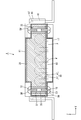
- the top view of the electrical storage unit of Embodiment 1 AA sectional view of FIG. BB sectional view of FIG. Disassembled front view of power storage unit Front view showing a state in which the bracket is held by the bracket receiving portion CC sectional view of FIG.
- the power storage unit 1 of the present embodiment is mounted on a vehicle, and is used, for example, as an auxiliary power source at the time of engine idle stop or engine restart.
- the X direction in the drawing is the right side
- the Y direction is the front
- the Z direction is the upper side.
- symbol may be attached
- the power storage unit 1 includes a holder 30 that holds a plurality of capacitors BT as power storage elements, and an electronic component P for controlling charging / discharging of the capacitors BT inside a metal case 10.
- a unit main body portion that accommodates a circuit board 50 on which (an example of a control circuit) is mounted is provided with a pair of brackets 60 for attachment to a vehicle at the front and rear.
- the storage element may be a secondary battery.
- the metal case 10 includes an upper case 11 having a substantially rectangular parallelepiped shape provided with a recess having a lower surface opening, and a lower case 17 having a flat substantially rectangular parallelepiped shape provided with a recess having an upper surface opening. Configured. Upper through-holes 12 are vertically provided at the four corners of the upper case 11, and lower through-holes 18 are vertically provided at the four corners of the lower case 17.
- the holder 30 is formed of an insulating synthetic resin material and has a flat rectangular box shape that is long on the left and right as a whole.
- the dimension of the holder 30 is such that it fits tightly in the upper case 11.
- Holder through-holes 32 are vertically provided at the four corners of the holder 30, and a metal collar 35 (an example of a connecting member) in which a screw groove (not shown) is formed in the inner peripheral surface of each holder through-hole 32. Are provided, and the upper and lower end surfaces thereof are exposed.
- a plurality of recesses 33 for accommodating the capacitor BT are provided side by side on the left and right sides of the center line in the length direction of the holder 30 as shown in FIG. 1. Yes.
- the capacitor BT is accommodated in each recess 33 of the holder 30 with the lead terminals W facing left and right outside.
- a holder cover 36 is put on the capacitor BT accommodated in the holder 30.
- the holder cover 36 is fixed to the holder 30 by being engaged with an engaging portion (not shown) provided on the holder 30.
- the holder cover 36 is formed of a synthetic resin material, and has a shape that is inclined from the front-rear direction end portion to the center, thereby suppressing the upward jumping of the capacitor BT.
- each lead terminal W of the capacitor BT extends up and down through the holder 30 as shown by a broken line in FIG.
- the circuit board 50 is formed in a substantially rectangular shape that is slightly smaller than the lower surface 52 of the holder 30. As shown in FIG. 2, the circuit board 50 is arranged such that the upper surface 51 is in contact with the rear surface of the holder 30, while the lower surface 52 is mounted with an electronic component P for controlling charge / discharge of the capacitor BT.
- the circuit board 50 is provided with a substrate through-hole 53 therethrough, and an upper surface 51 is provided with a land (not shown) at the periphery of each substrate through-hole 53 so as to form a ground pattern (an example of a predetermined line). ).
- the inner diameters of the lands and the substrate through holes 53 are approximately the same as the inner diameter of the collar 35 provided in the holder 30, and the upper surface of each land is in contact with the lower surface of each collar 35.
- the lower surface 52 of the circuit board 50 is covered with the lower case 17 of the metal case 10.
- the power storage unit 1 attaches a bracket 60 to the holder 30, thereby transmitting the load of the unit main body to the bracket 60, and the metal case 10, the holder 30, the circuit board 50, and the bracket 60.
- the front end side and the rear end side are provided with a configuration that allows electrical connection. Since the configuration on the front end side and the configuration on the rear end side are the same except that they are reversed in the front-rear direction, only the front end side will be described below, and description on the rear end side will be omitted.
- the front side wall 15 of the upper case 11 is provided with a contact piece 16 (an example of a connection portion) for electrical connection to the bracket 60.
- the contact piece 16 is formed by making cuts 13 symmetrically on the front side wall 15 with the center line in the length direction sandwiched therebetween, and leaving the cut in a tongue-like shape therebetween.
- An escape slit 14 is provided at the center of the contact piece 16 in the left-right direction to allow the locking projection 44 to escape when inserted into a bracket receiving portion 40 described later.
- the upper end of the escape slit 14 has an arc shape that matches the shape of the outer peripheral surface of the locking projection 44.
- the bracket 60 is formed in a strip shape from a relatively thick metal material, as shown in FIG.
- the distal end portion of the bracket 60 is bent at a right angle in the length direction to form an insertion piece portion 61 for engaging with a bracket receiving portion 40 described later.
- a locking hole 62 is formed in the vicinity of the end of the insertion piece 61 so as to penetrate therethrough.
- a hemispherical contact protrusion 63 is provided on the rear surface of the insertion piece 61.
- the contact protrusions 63 are provided below the locking holes 62, and are arranged one by one at symmetrical positions across the center line in the width direction of the insertion piece 61.
- a bracket receiving portion 40 for engaging with the bracket 60 projects from the center of the front side surface 31 of the holder 30 in the left-right direction.
- the bracket receiving portion 40 has a substantially rectangular parallelepiped shape that is flat in the front-rear direction.
- the bracket receiving portion 40 is formed with a pair of holding groove portions 41 that open to the lower surface 52, and an insertion slit 42 is provided on the upper surface 51 at a position near the front side surface 31 of the holder 30 so as to communicate with the holding groove portion 41. It has been.
- the dimension of the insertion slit 42 is such that the contact piece 16 can be inserted.
- a front opening 46 communicating with the holding groove 41 is opened along the center line in the left-right direction, while the rear inner wall 43 (the front side surface 31 of the holder 30) of the holding groove 41 is formed. ) Is provided with a thin cylindrical projection 44 protruding forward.
- the locking projection 44 extends into or near the front opening 46, and its tip is a free end that is not connected to the inner wall surface of the holding groove 41 or the inner wall surface of the front opening 46.
- the circuit board 50 and the holder 30 are accommodated in the metal case 10, and the upper case 11 and the lower case 17 are fitted to each other. Then, the contact piece 16 of the upper case 11 is inserted into the holding groove portion 41 from the insertion slit 42, and the rear surface of the holding groove portion 41 (the front side surface of the holder 30) is released while the locking protrusion 44 is released in the escape slit 14. 31) and with the front surface exposed in the holding groove 41.
- the insertion piece 61 of the bracket 60 is inserted into the holding groove 41 from below, the locking protrusion 44 is elastically deformed upward, and the contact protrusion 63 is rubbed against the front surface (exposed surface) of the contact piece 16.
- the inside of the holding groove 41 is caused to enter upward.
- the locking projection 44 fits into the locking hole 62 of the insertion piece 61 and returns to its original posture.
- the bracket 60 (insertion piece portion 61) is surrounded by the inner wall of the holding groove portion 41, and its tip can come into contact with the top surface 47 of the inner wall of the holding groove portion 41.
- the contact protrusion 63 contacts the contact piece 16 of the metal case 10 and is held in the metal. It will be in the state electrically connected with case 10.
- the holder 30 and the circuit board 50 are accommodated and fixed in the metal case 10, and the metal case 10, the holder 30, and the circuit board are engaged by engaging the bracket receiving portion 40 of the holder 30 with the bracket 60. All of 50 are electrically connected to the bracket 60 to complete the power storage module having the same potential.
- the load of the capacitor BT is transmitted from the holder 30 to the bracket 60 that engages with the bracket receiving portion 40 of the holder 30. Since the load is not transmitted to the bracket 60 via the metal case 10 as in the prior art, it is possible to prevent excessive stress from being generated at the joint between the metal case 10 and the bracket 60.
- the metal case 10 is provided with the contact piece 16 that is electrically connected to the bracket 60, the metal case 10 can be electrically connected to the vehicle body or the like of the vehicle via the bracket 60. Since the holder 30 does not need to be electrically connected to the bracket 60, the holder 30 does not need to be made of a conductive material, and can be formed of any material giving priority to strength and manufacturing cost.
- the holder 30 is held by the bracket 60 at the same time by simply inserting the bracket 60 into the holding groove portion 41. In contrast, it can be electrically connected.
- the bracket receiving portion 40 is configured to project from the front side portion 34 of the holder 30, whereas in the power storage unit 100 according to the present embodiment, as shown in FIG.
- the receiving portion 140 is recessed in the front side portion 134 of the holder 130 in a top view, and the front surface 145F of the front wall portion 145 is provided flush with the front surface 134F of the front side portion 134 of the holder 130.
- the bracket receiving part 140 is accommodated inside the metal case 110 covering the holder 130.
- the circuit board 150 has electronic components mounted not only on the lower surface 152 but also on the upper surface 151, and is arranged away from the lower surface of the holder 130.
- Holder through-holes 132 are provided at the four corners of the holder 130 so as to penetrate vertically, and each holder through-hole 132 is provided with a metal collar 135 having a thread groove (not shown) formed on the inner peripheral surface thereof. The end face is exposed.
- a spring piece 116 that protrudes rearward is integrally provided at the center of the front side wall 115 of the upper case 111, and the contact piece 116 for contacting the bracket 160. (An example of a connecting portion).
- the spring piece 116 is exposed in the holding groove 141 from the front side of the bracket receiving part 140 through the front opening 146 and is in contact with the bracket 160 inserted in the holding part.
- the insertion piece portion 161 of the bracket 160 is inserted into the lower slit 119 from below, and is press-fitted into the holding groove portion 141 of the bracket receiving portion 140 in the metal case 110, and into the holding groove portion 141.
- the spring piece 116 is exposed from the front side. From the center part of the front side 131 of the holder 130, a locking projection 144 is provided to project forward.
- bracket receiving portion 140 is accommodated inside the metal case 110, there is no possibility of being deformed by being pressed by another member from the outside. Therefore, it is suitable for a case where the installation space for the power storage module is narrow and there is a concern of coming into contact with other members due to vibration of the vehicle.
- the holding groove 41 of the bracket 60 is opened downward, and the bracket 60 is inserted from below, but the opening direction of the holding groove is not limited to this, for example, the holding groove is leftward.
- the bracket may be inserted from the left side.
- the holding groove part 41 provided in the bracket receiving part 40 has partitioned off the area
- the holding groove is not limited to this.
- a partition is provided between a region where the contact piece is disposed and a region where the insertion piece is disposed, and the contact protrusion is provided in one region of the partition. You may provide the opening part for being penetrated to the other area
- the shape of the contact piece is not limited to the shape as in the above embodiment, and may be provided on either the metal case or the bracket.
- the contact protrusion is provided on the bracket, but the contact protrusion may be provided on the contact piece.
- the spring piece 116 provided on the front side wall 115 of the metal case is configured to protrude from the front opening 146 into the holding groove 141, but instead, it is directed forward to the front side of the insertion piece. It is good also as a structure which the protrusion part which protrudes in this way is provided, this protrudes outside from front opening, and contacts the front side wall part of a metal case.
- the contact protrusion is not necessarily required, and the point is that the bracket and the metal case may be in contact and electrically connected.
- the holder 30 for holding the electricity storage element and the circuit board 50 are accommodated in the metal case 10, but the present invention is not limited to this, and only the holder for holding the electricity storage element is made of metal. It can also be applied to a power storage unit housed in a case.
- the structure for fixing the upper case and the lower case to the holder while being electrically connected is not limited to the structure in which the screw is screwed into the metal collar as in the first embodiment.
- a connecting member in place of the collar a metal stay having screw portions at both ends may be used, and a nut as a fastening member may be screwed into the metal stay.
- a structure in which a screw part is formed in the lower through hole of the lower case by burring and a screw inserted from the upper through hole of the upper case is screwed here, or a structure in which a bolt is fastened with a caulking nut is adopted. You can also.
- SYMBOLS 1,100 Power storage unit 10, 110: Metal case 11, 111: Upper case 15, 115: Front side wall 16: Contact piece (connection part) 17, 117: lower case 30, 130: holder 35, 135: collar 40, 140: bracket receiving portion 41, 141: holding groove portion 42: insertion slit 44, 144: locking projection 46: front opening 50: circuit board 60, 160: Brackets 61, 161: Insertion piece portions 62, 162: Locking hole 63: Contact protrusion BT: Capacitor P: Electronic component 116: Spring piece (connection portion)
Landscapes
- Chemical & Material Sciences (AREA)
- Chemical Kinetics & Catalysis (AREA)
- Electrochemistry (AREA)
- General Chemical & Material Sciences (AREA)
- Engineering & Computer Science (AREA)
- Power Engineering (AREA)
- Microelectronics & Electronic Packaging (AREA)
- Manufacturing & Machinery (AREA)
- Inorganic Chemistry (AREA)
- Aviation & Aerospace Engineering (AREA)
- Structural Engineering (AREA)
- Civil Engineering (AREA)
- Architecture (AREA)
- Mechanical Engineering (AREA)
- Battery Mounting, Suspending (AREA)
- Details Of Connecting Devices For Male And Female Coupling (AREA)
- Electric Double-Layer Capacitors Or The Like (AREA)
- Connection Or Junction Boxes (AREA)
- Sealing Battery Cases Or Jackets (AREA)
- Charge And Discharge Circuits For Batteries Or The Like (AREA)
Abstract
金属ケース10内に蓄電素子を収容してなり、金属製のブラケット60を介して車両に取り付けられる蓄電ユニット1であって、金属ケース10内で蓄電素子を保持するホルダ30と、ホルダ30に設けられブラケット60と係合してホルダ及び蓄電素子の荷重をブラケット60に与えるブラケット受部40と、金属ケース10に設けられブラケット60に接触して金属ケース10をブラケット60に電気的に接続する接続片16とを備える。
Description
本明細書は、蓄電ユニットに関する技術を開示する。
複数の蓄電素子を保持するホルダを金属ケース内に収容してなる蓄電ユニットとして、例えば特許文献1のものが知られている。この技術においては、金属ケースにブラケットを金属製のねじで留めつけ、これを介して蓄電ユニットを車両に固定すると同時に車両のグランドへの電気的な接続を得るようになっている。
しかしこの構成では、蓄電素子の大きな荷重をねじで受けるので、車両からの振動を受けたときに応力がねじに集中して、ねじの締め付けが緩んだり、ねじ自体が破損する原因となる。これを回避しつつ車両側との電気的接続を担保するため、ねじ留めに代えて金属ケースとブラケットとを直接溶接する構成が考えられる。しかしこれでは、比較的薄肉の金属ケースに対して比較的肉厚のブラケットを溶接することになるため、特に蓄電素子の重量に合わせてブラケットがいっそう肉厚となる場合に、技術的制約が大きい。また、金属ケースに部分的に補強したブラケット取付部を設け、このブラケット取付部にブラケットを取り付ける方法も考えられるが、この場合は金属ケースの成形コストが嵩んでしまう。
本発明は上記のような事情に基づいて完成されたものであって、蓄電ユニットを車両等の振動が予想される取付先に確実に取り付けるとともに、その金属ケースの電気的接続も確保できるようにすることを目的とする。
本明細書に開示された技術に係る蓄電ユニットは、金属ケース内に蓄電素子を収容してなり、金属製のブラケットを介して車両に取り付けられる蓄電ユニットであって、前記金属ケース内で前記蓄電素子を保持するホルダと、前記ホルダに設けられ前記ブラケットと係合して前記ホルダ及び前記蓄電素子の荷重を前記ブラケットに与えるブラケット受部と、前記金属ケースに設けられ前記ブラケットに接触して前記金属ケースを前記ブラケットに電気的に接続する接続部とを備える。
この構成によれば、蓄電素子の荷重はホルダから、ホルダのブラケット受部と係合するブラケットに伝えられる。従来のように荷重が金属ケースを介してブラケットに伝えられるのではないから、金属ケースとブラケットとの結合部に過剰な応力が発生することを防止できる。また、金属ケースにはブラケットに電気的に接続される接続部が設けられているから、金属ケースはブラケットを介して車両の車体等に電気的に接続することができる。ホルダはブラケットと電気的に接続される必要がないから、導電性の材料によって製造する必要がなく、強度や製造コストを優先した任意の材料で形成することが可能である。
本明細書に開示された配線モジュールに係る実施態様として、次の構成が好ましい。
(1)前記ブラケット受部は、前記ブラケットの先端に設けられた差込み片部を挿入可能な保持溝部 を備えると共に前記接続部は前記金属ケースに一体に設けられた接触片から構成され、前記接触片は前記保持溝部内において露出して、前記保持溝部内に挿入され保持された前記ブラケットの差込み片部と接触可能とされている。
この構成によれば、ブラケットを保持する保持溝部の内部に電気的な接続手段(接触片)が露出しているから、ブラケットを保持溝部に差し込むだけで、ホルダをブラケットで保持すると同時にブラケットに対して電気的に接続することができる。
(2)前記ブラケット受部は前記ホルダの側部に陥没して設けられ、前記金属ケースには、前記ホルダの側壁を外方から覆う壁部が設けられ、前記壁部には前記接触片としてばね片が設けられ、前記ばね片は側壁の外方から前記保持溝部内に突入して前記ブラケットの差込み片部部と接触可能とされている。
この構成によれば、ブラケット受部は前記金属ケースの内側に収容されるから、外方から他の部材に押圧されて変形するおそれがない。
(3)前記金属ケースは、前記ホルダの外側を互いに反対側から嵌合して覆う上ケース及び下ケースとから構成されると共に、前記ホルダには前記上下両ケースの嵌合方向に沿って延びる金属製の連結部材が設けられ、前記上ケース及び下ケースは前記連結部材に螺合させた締結部材により前記ホルダに固定されている。
この構成によれば、金属製のカラーを介して上ケースと下ケースとが電気的に接続されるから、上下両ケースをホルダに固定すると同時にこれらをシールドのために電気的に同電位とすることができる。
(4)前記金属ケース内には前記蓄電素子の充放電を制御する制御回路が実装された回路基板が収容され、その回路基板には前記連結部材を貫通させる貫通孔とその貫通孔の周縁に前記連結部材に接することで前記制御回路の所定のラインを前記金属ケースと同電位とするランドとが形成されている。
(4)前記金属ケース内には前記蓄電素子の充放電を制御する制御回路が実装された回路基板が収容され、その回路基板には前記連結部材を貫通させる貫通孔とその貫通孔の周縁に前記連結部材に接することで前記制御回路の所定のラインを前記金属ケースと同電位とするランドとが形成されている。
この構成によれば、ネジ部材をカラーに挿入して螺合させるだけで回路基板の所定のラインを金属ケースと同電位とすることができる。
(5)前記ホルダは合成樹脂製であって矩形の箱形をなしており、
前記ブラケット受部は前記ホルダの長辺の両側壁部の略中央に設けられている。
前記ブラケット受部は前記ホルダの長辺の両側壁部の略中央に設けられている。
この構成によれば、ブラケットがホルダの重心に近い位置で蓄電素子およびホルダの荷重を受けるので、ホルダの重心とブラケット受部との間で過剰な応力が発生することを防止できる。
本明細書に開示された技術に係る蓄電モジュールによれば、蓄電ユニットを車両等の振動が予想される取付先に確実に取り付けるとともに、その金属ケースの電気的接続も確保できる。
<実施形態1>
本明細書に開示された技術に係る実施形態1を、図1から図6によって説明する。
本明細書に開示された技術に係る実施形態1を、図1から図6によって説明する。
本実施形態の蓄電ユニット1は、車両に搭載され、例えば、エンジンのアイドルストップ時やエンジンの再始動時の補助電源として用いられる。以下では、図示におけるX方向を右方、Y方向を前方、Z方向を上方として説明する。また、以下の説明においては、複数の同一部材については一の部材にのみ符号を付し、他の部材の符号を省略することがある。
蓄電ユニット1は、図1から図3に示すように、金属ケース10の内部に、蓄電素子としての複数のキャパシタBTを保持するホルダ30と、キャパシタBTの充放電を制御するための電子部品P(制御回路の一例)が実装された回路基板50と、を収容してなるユニット本体部に、車両に取り付けるための一対のブラケット60を前後に備える。なお、蓄電素子は二次電池であってもよい。
金属ケース10は、図2に示すように、下面開口の凹部が設けられた略直方体形状の上ケース11と、上面開口の凹部が設けられた扁平な略直方体形状の下ケース17と、を備えて構成されている。上ケース11の四隅には上部貫通孔12が上下に貫通して設けられるとともに、下ケース17の四隅には下部貫通孔18が上下に貫通して設けられている。
ホルダ30は絶縁性の合成樹脂材から形成され、全体として左右に長い扁平な矩形の箱形をなしている。ホルダ30の寸法は、上ケース11内に緊密に嵌る程度となっている。ホルダ30の四隅にはホルダ貫通孔32が上下に貫通して設けられるとともに、各ホルダ貫通孔32には内周面に図示しないねじ溝が形成された金属製のカラー35(連結部材の一例)が設けられ、その上下端面が露出されている。
ホルダ30の上面側には、キャパシタBTを収容するための複数の凹部33が、図1に示すように、ホルダ30の長さ方向における中心線を挟んで左右一列ずつ前後に並んで設けられている。
ホルダ30の各凹部33には、キャパシタBTがそれぞれリード端子Wを左右外側に向けて収容されている。ホルダ30に収容されたキャパシタBTには、図3に示すように、ホルダカバー36が被せられている。ホルダカバー36は、ホルダ30に設けられた図示しない係合部に係合されることで、ホルダ30に対して固定されている。ホルダカバー36は合成樹脂材から形成されて前後方向端部から中央にかけて傾斜した形状をなしており、これによりキャパシタBTの上方への飛び出しが抑制されている。
なお、キャパシタBTの各リード端子Wは、図2に破線で示すように、ホルダ30を上下に貫通して裏面に延出されている。
回路基板50はホルダ30の下面52よりもやや小寸の略長方形状に形成されている。回路基板50は、図2に示すように、上面51がホルダ30の裏面と接して配される一方、下面52にはキャパシタBTの充放電を制御するための電子部品Pが実装されている。また、回路基板50には基板貫通孔53が貫通して設けられているとともに、その上面51には各基板貫通孔53の周縁に図示しないランドが設けられて、グランドパターン(所定のラインの一例)と接続されている。ランドおよび基板貫通孔53の内径は、ホルダ30に設けられたカラー35の内径とほぼ同寸となっており、各ランドの上面は各カラー35の下面と接触している。回路基板50の下面52は、金属ケース10の下ケース17で覆われている。
蓄電ユニット1は、図3に示すように、ホルダ30にブラケット60を取り付けることで、ユニット本体部の荷重をブラケット60に伝えるとともに、金属ケース10、ホルダ30、および回路基板50とブラケット60との電気的な接続が得られる構成を、前端側と後端側に備えている。前端側の構成と後端側の構成は前後逆である他は同一であるため、以下においては前端側のみについて説明し、後端側の説明は省略する。
上ケース11の前側壁15には、ブラケット60に電気的に接続するための接触片16(接続部の一例)が設けられている。接触片16は、図4に示すように、前側壁15にその長さ方向における中心線を挟んで左右対称に切り込み13を入れ、その間を舌片状に切残すことで形成されている。接触片16の左右方向における中央部には、後述するブラケット受部40内に挿入された際に係止突部44を逃がすための逃がしスリット14が設けられている。逃がしスリット14の上端部は、係止突部44の外周面の形状に合わせた円弧形状をなしている。
ブラケット60は、図3に示すように、比較的肉厚の金属材から帯状に形成されている。ブラケット60の先端部分は、長さ方向において直角に曲げられて、後述するブラケット受部40に係合するための差込み片部61とされている。差込み片部61の端部近傍には、図4に示すように、係止孔62が貫通して形成されている。また、差込み片部61の後面には、半球状の接触突部63が突設されている。接触突部63は、係止孔62よりも下部に設けられ、差込み片部61の幅方向における中心線を挟んで左右対称の位置に一つずつ配されている。
ホルダ30の前側面31の左右方向における中央には、ブラケット60と係合するためのブラケット受部40が突設されている。
ブラケット受部40は、図1および図4に示すように、全体として前後に扁平な略直方体形状をなしている。ブラケット受部40には、下面52に開口する一対の保持溝部41が形成されているとともに、上面51にはホルダ30の前側面31寄りの位置に挿通スリット42が保持溝部41に連通して設けられている。挿通スリット42の寸法は、接触片16が挿通可能な程度となっている。
ブラケット受部40の前壁部45には、保持溝部41と連通する前面開口部46が左右方向における中心線に沿って開口される一方、保持溝部41の後内壁43(ホルダ30の前側面31)の中央部からは、細い円柱形状の係止突部44が前方に突出して設けられている。係止突部44は前面開口部46内またはその近傍まで延出し、その先端は保持溝部41の内壁面や前面開口部46の内壁面に連結されない自由端となっている。
次に、本実施形態の蓄電ユニット1の組み立て手順を説明する。
まず、金属ケース10の内部に回路基板50およびホルダ30を収容して、上ケース11と下ケース17とを互いに嵌合させる。すると、上ケース11の接触片16は、挿通スリット42から保持溝部41に挿入され、逃がしスリット14において係止突部44を逃がしつつ、背面を保持溝部41の後内壁43(ホルダ30の前側面31)に沿わせ、かつ前面を保持溝部41内において露出させた状態で配される。
また、金属ケース10の内部に回路基板50およびホルダ30を収容する際には、ホルダ30の四隅に設けられた金属製のカラー35と、回路基板50の四隅に設けられたランドおよび基板貫通孔53とが、金属ケース10の四隅に設けられた上部貫通孔12および下部貫通孔18と同軸状になるように、位置合わせしておく。そして、これらに金属ケース10の上下から締結部材としてのビスSWを挿入し、金属製のカラー35のネジ孔に螺合させる。これにより、回路基板50および金属ケース10は、ホルダ30に固定されるるとともに、回路基板50のグランドパターンがランドを介して金属製のカラー35に導通状態となり、かつ、上ケース11及び下ケース17がビスSWを介してぞれぞれ金属製のカラー35に電気的に接続された状態となる。
そして、ブラケット60の差込み片部61を保持溝部41に下方から挿入し、係止突部44を上方に弾性変形させるとともに接触突部63を接触片16の前面(露出面)に擦接させながら保持溝部41内を上方に進入させる。すると、差込み片部61の係止孔62に係止突部44が嵌り、元の姿勢に弾性復帰する。これにより、図3および図5に示すように、ブラケット60(差込み片部61)は保持溝部41の内壁に包囲され、その先端が保持溝部41の内壁の頂面47と当接可能となるとともに係止突部44に係止してブラケット受部40内に係合して保持され、それと同時に、図6に示すように、接触突部63が金属ケース10の接触片16に接触して金属ケース10と電気的に接続された状態となる。
このように、金属ケース10内にホルダ30および回路基板50を収容して固定し、ホルダ30のブラケット受部40とブラケット60とを係合させることで、金属ケース10、ホルダ30、および回路基板50のすべてがブラケット60に電気的に接続されて同電位とされた蓄電モジュールが完成される。
上記の構成によれば、キャパシタBTの荷重はホルダ30から、ホルダ30のブラケット受部40と係合するブラケット60に伝えられる。従来のように荷重が金属ケース10を介してブラケット60に伝えられるのではないから、金属ケース10とブラケット60との結合部に過剰な応力が発生することを防止できる。また、金属ケース10にはブラケット60に電気的に接続される接触片16が設けられているから、金属ケース10はブラケット60を介して車両の車体等に電気的に接続することができる。ホルダ30はブラケット60と電気的に接続される必要がないから、導電性の材料によって製造する必要がなく、強度や製造コストを優先した任意の材料で形成することが可能である。
また、ブラケット60を保持する保持溝部41の内部に金属ケース10の接触片16が露出しているから、ブラケット60を保持溝部41に差し込むだけで、ホルダ30をブラケット60で保持すると同時にブラケット60に対して電気的に接続することができる。
<実施形態2>
次に、本明細書に開示された技術に係る実施形態2を図7から図10によって説明する。なお本実施形態においては実施形態と異なる構成のみ説明し、実施形態1と同様の構成については説明を省略する。
次に、本明細書に開示された技術に係る実施形態2を図7から図10によって説明する。なお本実施形態においては実施形態と異なる構成のみ説明し、実施形態1と同様の構成については説明を省略する。
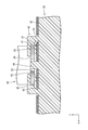
実施形態1の蓄電ユニット1においてはブラケット受部40はホルダ30の前側部34に突設される構成であるのに対し、本実施形態の蓄電ユニット100においては、図7に示すように、ブラケット受部140はホルダ130の前側部134に上面視で陥没し、その前壁部145の前面145Fをホルダ130の前側部134の前面134Fと面一にして設けられている。これにより、図8に示すように、ブラケット受部140はホルダ130を覆う金属ケース110の内側に収容されている。なお、回路基板150は下面152だけでなく上面151にも電子部品が実装され、ホルダ130の下面から離間して配されている。ホルダ130の四隅にはホルダ貫通孔132が上下に貫通して設けられるとともに、各ホルダ貫通孔132には内周面に図示しないねじ溝が形成された金属製のカラー135が設けられ、その上下端面が露出されている。
また、本実施形態においては、図9に示すように、上ケース111の前側壁115の中央に後方へ突出するばね片116が一体的に設けられて、ブラケット160と接触するための接触片116(接続部の一例)とされている。ばね片116は、ブラケット受部140の前面側から前面開口部146を通って保持溝部141内に露出し、保持部内に挿入されたブラケット160に接触している。
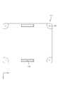
金属ケース110のうち下ケース117の前端部近傍の中央には、図10に示すように、左右に長い下スリット119が設けられている。ブラケット160の差込み片部161は、図8および図9に示すように、下方から下スリット119に挿通され、金属ケース110内においてブラケット受部140の保持溝部141に圧入され、保持溝部141内に前面側から露出するばね片116と接触している。ホルダ130の前側面131の中央部からは、係止突部144が前方に突出して設けられている。
この構成によれば、ブラケット受部140は前記金属ケース110の内側に収容されるから、外方から他の部材に押圧されて変形するおそれがない。したがって、蓄電モジュールの設置スペースが狭く、車両の振動により他の部材と当接する懸念がある場合等に好適である。
<他の実施形態>
本明細書に開示された技術は上記記述及び図面によって説明した実施形態に限定されるものではなく、例えば次のような形態で実施することが可能である。
本明細書に開示された技術は上記記述及び図面によって説明した実施形態に限定されるものではなく、例えば次のような形態で実施することが可能である。
(1)上記実施形態においては、ブラケット60の保持溝部41は下方に開口し、ブラケット60を下方から挿入する構成としているが、保持溝部の開口方向はこれに限らず、例えば保持溝部が左方に開口し、ブラケットを左方から挿入する構成としてもよい。
(2)また上記実施形態においては、ブラケット受部40の内部に設けられた保持溝部41は、接触片16が配される領域と差込み片部61が配される領域との間が仕切られていない構成としているが、保持溝部はこれに限らず、例えば接触片が配される領域と差込み片部が配される領域との間に隔壁を設けて、この隔壁に接触突部が一方の領域から他方の領域へ挿通されるための開口部を設けてもよい。
(3)接触片部の形状は、上記実施形態のような形状に限らず、また金属ケースとブラケットのどちらに設けてもよい。例えば、実施形態1においては接触突部はブラケットに設けられているが、接触突部は接触片に設けてもよい。また、実施形態2においては金属ケースの前側壁115に設けたばね片116が前面開口部146から保持溝部141に突入する構成としているが、これに代えて、差込み片部の前面側に前方に向かって突出する突状部が設けられ、これが前面開口から外部へ突出して、金属ケースの前側壁部に接触する構成としてもよい。さらに、接触突部は必ずしも必要ではなく、要はブラケットと金属ケースとが接触して電気的に接続されればよい。
(4)上記実施形態においては、金属ケース10内に蓄電素子を保持するホルダ30と回路基板50とを収容しているが、本願発明はこれに限らず、蓄電素子を保持するホルダのみを金属ケース内に収めた蓄電ユニットにも適用することができる。
(5)上ケースと下ケースとを電気的に接続しつつホルダに固定する構造としては、前記第1実施形態のような金属製のカラーにビスを螺合させる構造に限らず、例えば金属製のカラーに代わる連結部材として、両端にネジ部を有する金属スティを利用し、ここに締結部材としてのナットを螺合する構造としてもよい。または、下ケースの下部貫通孔にバーリング加工によりネジ部を形成し、ここに上ケースの上部貫通孔から差し込んだビスを螺合させる構造や、またはボルトをかしめナットで締結する構造等を採用することもできる。
1、100:蓄電ユニット
10、110:金属ケース
11、111:上ケース
15、115:前側壁
16:接触片(接続部)
17、117:下ケース
30、130:ホルダ
35、135:カラー
40、140:ブラケット受部
41、141:保持溝部
42:挿通スリット
44、144:係止突部
46:前面開口部
50:回路基板
60、160:ブラケット
61、161:差込み片部
62、162:係止孔
63:接触突部
BT:キャパシタ
P:電子部品
116:ばね片(接続部)
10、110:金属ケース
11、111:上ケース
15、115:前側壁
16:接触片(接続部)
17、117:下ケース
30、130:ホルダ
35、135:カラー
40、140:ブラケット受部
41、141:保持溝部
42:挿通スリット
44、144:係止突部
46:前面開口部
50:回路基板
60、160:ブラケット
61、161:差込み片部
62、162:係止孔
63:接触突部
BT:キャパシタ
P:電子部品
116:ばね片(接続部)
Claims (6)
- 金属ケース内に蓄電素子を収容してなり、金属製のブラケットを介して車両に取り付けられる蓄電ユニットであって、
前記金属ケース内で前記蓄電素子を保持するホルダと、前記ホルダに設けられ前記ブラケットと係合して前記ホルダ及び前記蓄電素子の荷重を前記ブラケットに与えるブラケット受部と、前記金属ケースに設けられ前記ブラケットに接触して前記金属ケースを前記ブラケットに電気的に接続する接続部とを備える蓄電ユニット。 - 前記ブラケット受部は、前記ブラケットの先端に設けられた差込み片部を挿入可能な保持溝部を備えると共に前記接続部は前記金属ケースに一体に設けられた接触片から構成され、前記接触片は前記保持溝部内において露出して、前記保持溝部内に挿入され保持された前記ブラケットの差込み片部と接触可能とされている、請求項1に記載の蓄電ユニット。
- 前記ブラケット受部は前記ホルダの側部に陥没して設けられ、前記金属ケースには、前記ホルダの側壁を外方から覆う壁部が設けられ、前記壁部には前記接触片としてばね片が設けられ、前記ばね片は側壁の外方から前記保持溝部内に突入して前記ブラケットの差込み片部と接触可能とされている、請求項2に記載の蓄電ユニット。
- 前記金属ケースは、前記ホルダの外側を互いに反対側から嵌合して覆う上ケース及び下ケースとから構成されると共に、前記ホルダには前記上下両ケースの嵌合方向に沿って延びる金属製の連結部材が設けられ、前記上ケース及び下ケースは前記連結部材に螺合させた締結部材により前記ホルダに固定されている請求項1から請求項3のいずれか一項に記載の蓄電ユニット。
- 前記金属ケース内には前記蓄電素子の充放電を制御する制御回路が実装された回路基板が収容され、その回路基板には前記連結部材を貫通させる貫通孔とその貫通孔の周縁に前記連結部材に接することで前記制御回路の所定のラインを前記金属ケースと同電位とするランドとが形成されている請求項4記載の蓄電ユニット。
- 前記ホルダは合成樹脂製であって矩形の箱形をなしており、
前記ブラケット受部は前記ホルダの長辺の両側壁部の略中央に設けられている、請求項1から請求項5のいずれか一項に記載の蓄電ユニット。
Priority Applications (2)
| Application Number | Priority Date | Filing Date | Title |
|---|---|---|---|
| US16/488,104 US11094986B2 (en) | 2017-02-27 | 2018-02-07 | Power storage unit |
| CN201880010783.8A CN110301021B (zh) | 2017-02-27 | 2018-02-07 | 蓄电单元 |
Applications Claiming Priority (2)
| Application Number | Priority Date | Filing Date | Title |
|---|---|---|---|
| JP2017034627A JP6802977B2 (ja) | 2017-02-27 | 2017-02-27 | 蓄電ユニット |
| JP2017-034627 | 2017-02-27 |
Publications (1)
| Publication Number | Publication Date |
|---|---|
| WO2018155182A1 true WO2018155182A1 (ja) | 2018-08-30 |
Family
ID=63254248
Family Applications (1)
| Application Number | Title | Priority Date | Filing Date |
|---|---|---|---|
| PCT/JP2018/004150 Ceased WO2018155182A1 (ja) | 2017-02-27 | 2018-02-07 | 蓄電ユニット |
Country Status (4)
| Country | Link |
|---|---|
| US (1) | US11094986B2 (ja) |
| JP (1) | JP6802977B2 (ja) |
| CN (1) | CN110301021B (ja) |
| WO (1) | WO2018155182A1 (ja) |
Cited By (1)
| Publication number | Priority date | Publication date | Assignee | Title |
|---|---|---|---|---|
| JP2019067565A (ja) * | 2017-09-29 | 2019-04-25 | 本田技研工業株式会社 | バッテリパック |
Families Citing this family (6)
| Publication number | Priority date | Publication date | Assignee | Title |
|---|---|---|---|---|
| JP7116364B2 (ja) * | 2018-11-22 | 2022-08-10 | マツダ株式会社 | バッテリ、及びバッテリへの導電線の接続、取り外し方法 |
| JP7081506B2 (ja) * | 2019-01-11 | 2022-06-07 | 株式会社オートネットワーク技術研究所 | 電気接続箱 |
| JP2020136556A (ja) * | 2019-02-22 | 2020-08-31 | 住友電装株式会社 | 蓄電ユニット |
| JP2020137323A (ja) * | 2019-02-22 | 2020-08-31 | 住友電装株式会社 | 電気接続箱 |
| JP2021072176A (ja) * | 2019-10-29 | 2021-05-06 | 三菱自動車工業株式会社 | 車両用電池パック |
| KR102844982B1 (ko) * | 2020-12-29 | 2025-08-12 | 에스케이온 주식회사 | 배터리 모듈 |
Citations (5)
| Publication number | Priority date | Publication date | Assignee | Title |
|---|---|---|---|---|
| JP2014082844A (ja) * | 2012-10-15 | 2014-05-08 | Auto Network Gijutsu Kenkyusho:Kk | 電気接続箱 |
| JP2014143042A (ja) * | 2013-01-23 | 2014-08-07 | Kojima Press Industry Co Ltd | 車両搭載用電池ケース |
| JP2014236037A (ja) * | 2013-05-31 | 2014-12-15 | ダイキョーニシカワ株式会社 | 電磁波遮蔽容器 |
| JP2014239095A (ja) * | 2013-06-06 | 2014-12-18 | 株式会社オートネットワーク技術研究所 | 補助電源装置及び電気接続箱 |
| WO2016147900A1 (ja) * | 2015-03-19 | 2016-09-22 | 株式会社オートネットワーク技術研究所 | 蓄電パック |
Family Cites Families (5)
| Publication number | Priority date | Publication date | Assignee | Title |
|---|---|---|---|---|
| JP5553163B2 (ja) * | 2010-09-09 | 2014-07-16 | ソニー株式会社 | バッテリユニット |
| JP6221994B2 (ja) * | 2014-08-08 | 2017-11-01 | 株式会社Gsユアサ | 蓄電装置 |
| JP6413637B2 (ja) | 2014-10-30 | 2018-10-31 | 株式会社オートネットワーク技術研究所 | 蓄電ユニット |
| JP6380043B2 (ja) * | 2014-11-21 | 2018-08-29 | 株式会社オートネットワーク技術研究所 | 蓄電モジュール |
| JP6278243B2 (ja) * | 2015-01-07 | 2018-02-14 | 株式会社オートネットワーク技術研究所 | 蓄電ユニット |
-
2017
- 2017-02-27 JP JP2017034627A patent/JP6802977B2/ja not_active Expired - Fee Related
-
2018
- 2018-02-07 CN CN201880010783.8A patent/CN110301021B/zh not_active Expired - Fee Related
- 2018-02-07 US US16/488,104 patent/US11094986B2/en not_active Expired - Fee Related
- 2018-02-07 WO PCT/JP2018/004150 patent/WO2018155182A1/ja not_active Ceased
Patent Citations (5)
| Publication number | Priority date | Publication date | Assignee | Title |
|---|---|---|---|---|
| JP2014082844A (ja) * | 2012-10-15 | 2014-05-08 | Auto Network Gijutsu Kenkyusho:Kk | 電気接続箱 |
| JP2014143042A (ja) * | 2013-01-23 | 2014-08-07 | Kojima Press Industry Co Ltd | 車両搭載用電池ケース |
| JP2014236037A (ja) * | 2013-05-31 | 2014-12-15 | ダイキョーニシカワ株式会社 | 電磁波遮蔽容器 |
| JP2014239095A (ja) * | 2013-06-06 | 2014-12-18 | 株式会社オートネットワーク技術研究所 | 補助電源装置及び電気接続箱 |
| WO2016147900A1 (ja) * | 2015-03-19 | 2016-09-22 | 株式会社オートネットワーク技術研究所 | 蓄電パック |
Cited By (2)
| Publication number | Priority date | Publication date | Assignee | Title |
|---|---|---|---|---|
| JP2019067565A (ja) * | 2017-09-29 | 2019-04-25 | 本田技研工業株式会社 | バッテリパック |
| US11217852B2 (en) | 2017-09-29 | 2022-01-04 | Honda Motor Co., Ltd. | Battery pack |
Also Published As
| Publication number | Publication date |
|---|---|
| US11094986B2 (en) | 2021-08-17 |
| US20200067033A1 (en) | 2020-02-27 |
| CN110301021B (zh) | 2021-07-30 |
| JP6802977B2 (ja) | 2020-12-23 |
| CN110301021A (zh) | 2019-10-01 |
| JP2018142571A (ja) | 2018-09-13 |
Similar Documents
| Publication | Publication Date | Title |
|---|---|---|
| WO2018155182A1 (ja) | 蓄電ユニット | |
| US10010006B2 (en) | Electronic control device and method of manufacturing electronic control device | |
| JP2004079576A (ja) | 電子制御装置 | |
| JP2019213419A (ja) | 電気接続箱 | |
| US10063040B1 (en) | Electrical connection box and wire harness | |
| US8710377B2 (en) | Electric connection box | |
| US7244141B2 (en) | Electric connector box | |
| JP6211030B2 (ja) | 電子制御装置および電子制御装置の製造方法 | |
| JP2015088233A (ja) | コネクタ | |
| JP5946023B2 (ja) | 電気回路装置 | |
| JP2023001851A (ja) | バスバカバーおよびバスバの配索構造 | |
| US6827606B2 (en) | Connector with mounting ribs for mounting to a circuit board | |
| JP2018201296A (ja) | 電気接続箱 | |
| JP2003282361A (ja) | コンデンサモジュール | |
| JP2019008918A (ja) | 電子部品ユニット、ワイヤハーネス、及び、コネクタ固定構造 | |
| JP5236256B2 (ja) | 対のリード線短絡防止キャップおよび配線連結部短絡防止カバーからなる短絡防止具 | |
| JP2005100844A (ja) | 電子部品組付け体 | |
| JP2020173174A (ja) | バッテリー状態検知装置 | |
| JP2017216419A (ja) | 電子機器、及び電子機器の製造方法 | |
| JP5531565B2 (ja) | 電気接続箱及び電気接続箱の製造方法 | |
| JP2000033848A (ja) | エアバッグ制御装置 | |
| JP2001298294A (ja) | 電子ユニットのシールド構造 | |
| JP5929827B2 (ja) | 電気機器装置 | |
| JP2006093464A (ja) | 配線基板のアース構造及びそれを備えた冷蔵庫 | |
| JP6148599B2 (ja) | コネクタ |
Legal Events
| Date | Code | Title | Description |
|---|---|---|---|
| 121 | Ep: the epo has been informed by wipo that ep was designated in this application |
Ref document number: 18757226 Country of ref document: EP Kind code of ref document: A1 |
|
| NENP | Non-entry into the national phase |
Ref country code: DE |
|
| 122 | Ep: pct application non-entry in european phase |
Ref document number: 18757226 Country of ref document: EP Kind code of ref document: A1 |