WO2018154883A1 - 圧力センサ - Google Patents
圧力センサ Download PDFInfo
- Publication number
- WO2018154883A1 WO2018154883A1 PCT/JP2017/041500 JP2017041500W WO2018154883A1 WO 2018154883 A1 WO2018154883 A1 WO 2018154883A1 JP 2017041500 W JP2017041500 W JP 2017041500W WO 2018154883 A1 WO2018154883 A1 WO 2018154883A1
- Authority
- WO
- WIPO (PCT)
- Prior art keywords
- pressure
- pressure sensor
- engine
- unit
- pressure detection
- Prior art date
- Legal status (The legal status is an assumption and is not a legal conclusion. Google has not performed a legal analysis and makes no representation as to the accuracy of the status listed.)
- Ceased
Links
Images




Classifications
-
- F—MECHANICAL ENGINEERING; LIGHTING; HEATING; WEAPONS; BLASTING
- F02—COMBUSTION ENGINES; HOT-GAS OR COMBUSTION-PRODUCT ENGINE PLANTS
- F02D—CONTROLLING COMBUSTION ENGINES
- F02D35/00—Controlling engines, dependent on conditions exterior or interior to engines, not otherwise provided for
- F02D35/02—Controlling engines, dependent on conditions exterior or interior to engines, not otherwise provided for on interior conditions
- F02D35/023—Controlling engines, dependent on conditions exterior or interior to engines, not otherwise provided for on interior conditions by determining the cylinder pressure
-
- G—PHYSICS
- G01—MEASURING; TESTING
- G01L—MEASURING FORCE, STRESS, TORQUE, WORK, MECHANICAL POWER, MECHANICAL EFFICIENCY, OR FLUID PRESSURE
- G01L23/00—Devices or apparatus for measuring or indicating or recording rapid changes, such as oscillations, in the pressure of steam, gas, or liquid; Indicators for determining work or energy of steam, internal-combustion, or other fluid-pressure engines from the condition of the working fluid
- G01L23/08—Devices or apparatus for measuring or indicating or recording rapid changes, such as oscillations, in the pressure of steam, gas, or liquid; Indicators for determining work or energy of steam, internal-combustion, or other fluid-pressure engines from the condition of the working fluid operated electrically
- G01L23/18—Devices or apparatus for measuring or indicating or recording rapid changes, such as oscillations, in the pressure of steam, gas, or liquid; Indicators for determining work or energy of steam, internal-combustion, or other fluid-pressure engines from the condition of the working fluid operated electrically by resistance strain gauges
-
- G—PHYSICS
- G01—MEASURING; TESTING
- G01L—MEASURING FORCE, STRESS, TORQUE, WORK, MECHANICAL POWER, MECHANICAL EFFICIENCY, OR FLUID PRESSURE
- G01L19/00—Details of, or accessories for, apparatus for measuring steady or quasi-steady pressure of a fluent medium insofar as such details or accessories are not special to particular types of pressure gauges
- G01L19/0007—Fluidic connecting means
- G01L19/0038—Fluidic connecting means being part of the housing
-
- G—PHYSICS
- G01—MEASURING; TESTING
- G01L—MEASURING FORCE, STRESS, TORQUE, WORK, MECHANICAL POWER, MECHANICAL EFFICIENCY, OR FLUID PRESSURE
- G01L19/00—Details of, or accessories for, apparatus for measuring steady or quasi-steady pressure of a fluent medium insofar as such details or accessories are not special to particular types of pressure gauges
- G01L19/0061—Electrical connection means
- G01L19/0069—Electrical connection means from the sensor to its support
-
- G—PHYSICS
- G01—MEASURING; TESTING
- G01L—MEASURING FORCE, STRESS, TORQUE, WORK, MECHANICAL POWER, MECHANICAL EFFICIENCY, OR FLUID PRESSURE
- G01L19/00—Details of, or accessories for, apparatus for measuring steady or quasi-steady pressure of a fluent medium insofar as such details or accessories are not special to particular types of pressure gauges
- G01L19/04—Means for compensating for effects of changes of temperature, i.e. other than electric compensation
-
- G—PHYSICS
- G01—MEASURING; TESTING
- G01L—MEASURING FORCE, STRESS, TORQUE, WORK, MECHANICAL POWER, MECHANICAL EFFICIENCY, OR FLUID PRESSURE
- G01L19/00—Details of, or accessories for, apparatus for measuring steady or quasi-steady pressure of a fluent medium insofar as such details or accessories are not special to particular types of pressure gauges
- G01L19/14—Housings
- G01L19/148—Details about the circuit board integration, e.g. integrated with the diaphragm surface or encapsulation
-
- G—PHYSICS
- G01—MEASURING; TESTING
- G01L—MEASURING FORCE, STRESS, TORQUE, WORK, MECHANICAL POWER, MECHANICAL EFFICIENCY, OR FLUID PRESSURE
- G01L27/00—Testing or calibrating of apparatus for measuring fluid pressure
- G01L27/002—Calibrating, i.e. establishing true relation between transducer output value and value to be measured, zeroing, linearising or span error determination
- G01L27/005—Apparatus for calibrating pressure sensors
-
- F—MECHANICAL ENGINEERING; LIGHTING; HEATING; WEAPONS; BLASTING
- F02—COMBUSTION ENGINES; HOT-GAS OR COMBUSTION-PRODUCT ENGINE PLANTS
- F02D—CONTROLLING COMBUSTION ENGINES
- F02D45/00—Electrical control not provided for in groups F02D41/00 - F02D43/00
Definitions
- the present invention relates to a pressure sensor.
- Patent Document 1 includes a sensing structure to which a sensing element is attached, and an electronic circuit that processes a signal obtained from the sensing element.
- the sensing structure is disposed near a combustion chamber of a combustion engine.
- a pressure measurement plug is described that is located outside the combustion engine away from the sensing structure.
- the pressure sensor detects a combustion pressure of an engine, and when the pressure sensor is attached to the engine, a contact portion that directly or indirectly contacts the casing of the engine;
- a pressure detection unit that detects a combustion pressure and outputs a signal corresponding to the pressure, and the pressure detection unit detects the combustion pressure and outputs a signal, and a pressure detection element that is obtained from the pressure detection element.
- a circuit unit that converts the received signal into a signal corresponding to the pressure, and the pressure detection unit is located inside the engine with respect to the contact unit when the pressure sensor is attached to the engine. It is provided in a place to do.
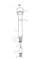
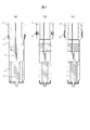
- FIG. 1 is an external view of a pressure sensor according to an embodiment of the present invention.
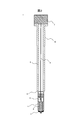
- FIG. 2 is an exploded view of a pressure sensor according to an embodiment of the present invention.
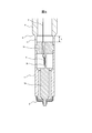
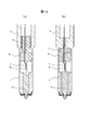
- FIG. 3 is a cross-sectional view of a pressure sensor according to an embodiment of the present invention.
- the pressure sensor 1 is attached to an engine which is an internal combustion engine such as a vehicle, detects the combustion pressure of the engine, and outputs a sensor output corresponding to the combustion pressure to the outside.
- the pressure sensor 1 includes a diaphragm 2, a cover 4, a housing 6, and a terminal portion 7.
- the housing 6 is provided with a screw portion 10 for fixing the pressure sensor 1 to the engine housing, and a contact portion 9 that comes into contact with the engine housing when the pressure sensor 1 is attached to the engine. Yes.
- the pressure transmission rod 3 and the pressure detection unit 5 are accommodated in the cover 4.
- the pressure detection unit 5 and the terminal unit 7 are connected by a signal line 8.
- the diaphragm 2 is disposed in contact with the pressure transmission rod 3 and the cover 4. Due to this arrangement, the diaphragm 2 has a function of applying a compressive force to the pressure transmission rod 3 by being deformed by receiving the combustion pressure of the engine and a function of preventing the combustion gas inside the engine from entering the sensor 1. .
- the pressure transmission rod 3 is provided with a pressure detector 5.
- the pressure transmission rod 3 is a pressure transmission mechanism that transmits the combustion pressure of the engine to the pressure detection unit 5 by generating distortion within a range including the installation position of the pressure detection unit 5 according to the compression force received from the diaphragm 2.
- the pressure detection unit 5 detects the combustion pressure of the engine by detecting the strain of the pressure transmission rod 3, and outputs a pressure signal corresponding to the detection result to the terminal unit 7 via the signal line 8.
- the pressure signal is output from the terminal portion 7 to the outside of the pressure sensor 1 as a sensor output.
- a circuit that generates a sensor output by performing signal processing such as output adjustment on the pressure signal obtained from the pressure detection unit 5 and outputs the sensor output to the outside may be provided in the terminal unit 7.
- FIG. 4 is a diagram showing a schematic configuration of the pressure detection unit 5.
- a pressure detection element 5 a provided in the central portion and a circuit unit 5 b provided around the pressure detection element 5 are formed on the same substrate.
- the pressure detection element 5a is configured using, for example, a strain gauge or the like, and detects the combustion pressure of the engine by detecting the amount of strain generated in the pressure transmission rod 3 in accordance with the combustion pressure of the engine.
- the pressure detection element 5a outputs a signal corresponding to the detected strain amount, that is, the combustion pressure of the engine, to the circuit unit 5b.
- the circuit unit 5b performs signal processing of processing on the signal obtained from the pressure detection element 5a, converts the signal into a pressure signal corresponding to the sensor output, and outputs the pressure signal to the terminal unit 7.
- the circuit unit 5b has a function of analog amplification of a weak signal obtained from the pressure detection element 5a and a function of digitally converting a weak signal obtained from the pressure detection element 5a. Further, the circuit unit 5b may have a function of detecting the ambient temperature and correcting the temperature. In the pressure detection unit 5, since the pressure detection element 5a is in the vicinity of the circuit unit 5b, temperature correction can be performed on the signal from the pressure detection element 5a using a temperature sensor built in the circuit unit 5b. Therefore, temperature correction can be realized with an inexpensive configuration.
- the pressure detection element 5a and the circuit unit 5b are formed on the same substrate in the pressure detection unit 5. Therefore, the wiring length connecting the pressure detection element 5a and the circuit unit 5b is greatly shortened, and as a result, the influence of noise from the outside can be reduced.
- the pressure detection element 5a and the circuit unit 5b are formed on the same substrate. However, if the proximity of the noise can be sufficiently reduced, they are separated on different substrates. May be arranged.
- the pressure detection unit 5 is provided at a location located inside the engine with respect to the contact unit 9 when the pressure sensor 1 is attached to the engine. Since the circuit part 5b generally has lower heat resistance than the pressure detection element 5a, in order to dispose the circuit part 5b in the vicinity of the pressure detection element 5a, a structure that can sufficiently dissipate the circuit part 5b in the pressure sensor 1 is required. Become. In the present embodiment, as described above, when the pressure sensor 1 is attached to the engine, the contact portion 9 comes into contact with the casing of the engine, thereby realizing the heat dissipation structure of the circuit portion 5b.
- the contact portion 9 is disposed in the vicinity of the pressure detection structure constituted by the pressure transmission rod 3 and the pressure detection portion 5, and a heat dissipation function for radiating the heat of the pressure detection structure to the engine casing by thermal contact.
- the contact portion 9 is in close contact with the casing of the engine to shield the high-temperature combustion gas inside the engine, and shields the combustion gas from entering the rear end side of the pressure sensor 1 from the contact portion 9. It has a function. Since the contact part 9 has these functions, the temperature rise of the circuit part 5b having a relatively low heat-resistant temperature can be suppressed.
- the contact part 9 may have only any one of said heat dissipation function and shielding function. Further, as long as the heat dissipation function and the shielding function can be sufficiently exhibited, the contact between the contact portion 9 and the engine casing may be direct, or may be indirect via another member. .
- FIG. 5 is an enlarged cross-sectional view of a portion including the pressure detection structure of the pressure sensor 1 according to the first embodiment of the present invention.
- the pressure transmission rod 3 includes a pressure transmission part 3a, an element installation part 3b, and a high rigidity part 3c.
- the pressure transmission part 3a is in contact with the diaphragm 2, and is provided at a location located on the inner side of the engine than the element installation part 3b and the high rigidity part 3c when the pressure sensor 1 is attached to the engine.
- the pressure transmission unit 3a transmits the compressive force received from the diaphragm 2 to the element installation unit 3b.
- the element installation portion 3b has a lower rigidity than the high-rigidity portion 3c, and is a portion that generates distortion according to the compressive force transmitted from the pressure transmission portion 3a.
- a flat surface having a shape obtained by cutting a part of the pressure transmission unit 3a is formed in the element installation unit 3b, and the pressure detection unit 5 is fixed to the flat surface.
- a flat surface having a shape obtained by cutting a part of the pressure transmission unit 3a is formed on the element installation unit 3b on the opposite side of the surface on which the pressure detection unit 5 is fixed.
- the high-rigidity portion 3c is set such that the cross-sectional area of the surface perpendicular to the axial direction of the pressure sensor 1 is larger than that of the element installation portion 3b, and has higher rigidity than the element installation portion 3b.
- the highly rigid part 3c has a function which receives the compressive force transmitted from the pressure transmission part 3a, and maximizes the distortion amount in the element installation part 3b.
- the high-rigidity portion 3c is disposed between the element installation portion 3b and the contact portion 9.
- the high-rigidity portion 3c is connected to the element installation portion 3b inside the engine than the contact portion 9. To do. Therefore, the deformation of the pressure sensor 1 generated from the contact portion 9 when the pressure sensor 1 is fixed to the engine can be attenuated in the high-rigidity portion 3c, and the generation of distortion in the element installation portion 3b can be suppressed. As a result, fluctuations in sensor output that occur when the pressure sensor 1 is attached can be suppressed.
- 3 and 5 show a configuration in which the high-rigidity portion 3c is disposed between the housing 6 and the cover 4, and the high-rigidity portion 3c is in direct contact with the housing 6. It is good also as a structure which made the rigid part 3c contact the housing
- the casing 6 and the cover 4 are joined by welding or the like, and the high rigidity portion 3 c is disposed in contact with the cover 4 so that the high rigidity portion 3 c is connected to the casing 6 via the cover 4. It may be a simple configuration.
- the stress absorbing portion 11 is a portion for absorbing deformation stress generated when the contact portion 9 comes into contact with the casing of the engine. Since the stress absorbing portion 11 is lower in rigidity than the high-rigidity portion 3c, the stress applied to the high-rigidity portion 3c by the deformation of the pressure sensor 1 generated from the contact portion 9 when the pressure sensor 1 is fixed to the engine. Has a function to reduce stress.
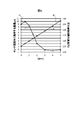
- FIG. 6 shows an example of the relationship between the length L of the stress absorbing portion 11 and the amount of strain of the element installing portion 3b generated when the pressure sensor 1 is fixed, and the temperature of the circuit portion 5b in the pressure detecting portion 5 during engine combustion.
- a graph 61 represents the amount of strain of the element installation portion 3b
- a graph 62 represents the temperature of the circuit portion 5b.
- the thermal conductivity from the pressure detection unit 5 to the contact unit 9 decreases as the length L of the stress absorbing unit 11 increases, so that the temperature of the circuit unit 5b increases. . That is, the effect of the stress reducing function by the stress absorbing unit 11 is in a trade-off relationship with the heat dissipation of the pressure detecting unit 5.
- the strain amount of the element installation portion 3b generated when the pressure sensor 1 is fixed is almost saturated when the length L of the stress absorbing portion 11 is 3 mm or more as shown in the graph 61.
- the temperature of the circuit portion 5 b rises in proportion to the length L of the stress absorbing portion 11 as shown in the graph 62. Therefore, if the pressure detection unit 5 is designed so that the temperature of the circuit unit 5b when the length L of the stress absorption unit 11 is about 3 mm is equal to or lower than the heat resistant temperature, the effect of the stress reduction function by the stress absorption unit 11 is maximized. Necessary heat dissipation can be ensured while exerting the limit.
- the length L of the stress absorbing part 11 is set to 3 mm, the amount of distortion of the element installation part 3b is suppressed, and the fluctuation of the sensor output caused when the pressure sensor 1 is attached Can be minimized. If the required sensor output can be obtained, it is advantageous in terms of cost to make the heat resistant temperature of the circuit portion 5b as low as possible. Therefore, the length L of 3 mm and the heat resistant temperature of 150 ° C. are examples, and the present invention is not limited thereto. Absent.
- the pressure transmission portion 3a, the element installation portion 3b, and the high-rigidity portion 3c are integrally formed as the pressure transmission rod 3. Further, the high rigidity portion 3c and the stress absorbing portion 11 are integrated by welding or the like. Furthermore, the stress absorbing portion 11 is integrally formed with the contact portion 9 continuously. With such a configuration, the pressure detection unit 5 installed in the element installation unit 3b is thermally connected continuously from the element installation unit 3b to the contact unit 9 via the high rigidity unit 3c and the stress absorption unit 11. Can be efficiently radiated to the engine housing to which the pressure sensor 1 is attached.
- the temperature rise of the circuit part 5b can be suppressed and it can be made into below heat-resistant temperature.
- the high rigidity portion 3c, the stress absorbing portion 11, and the contact portion 9 as long as they can be thermally connected continuously, for example, integral formation, welding, soldering, soldering, etc. Any connection method such as bonding, press-fitting, and shrink fitting can be used.
- the high-rigidity portion 3 c may be brought into direct contact with the contact portion 9 without providing the stress absorbing portion 11.
- the heat transfer distance from the pressure detection unit 5 to the contact unit 9 is short.
- efficient heat dissipation is possible.
- the wiring length connecting the pressure detection element 5a and the circuit unit 5b is greatly reduced while suppressing the temperature rise of the circuit unit 5b in the pressure detection unit 5. Shortened to Therefore, the influence of external noise can be reduced.
- the pressure sensor 1 that detects the combustion pressure of the engine detects the combustion pressure of the engine and the contact portion 9 that directly or indirectly contacts the casing of the engine when the pressure sensor 1 is attached to the engine. And a pressure detector 5 that outputs a sensor output to the outside of the pressure sensor 1.
- the pressure detection unit 5 includes a pressure detection element 5a that detects a combustion pressure of the engine and outputs a signal, and a circuit unit 5b that converts a signal obtained from the pressure detection element 5a into a pressure signal corresponding to the sensor output. .
- the pressure detection unit 5 is provided at a location located inside the engine relative to the contact unit 9 when the pressure sensor 1 is attached to the engine. Since it did in this way, the pressure sensor which was strong in the noise from the outside and improved the detection accuracy can be provided.
- the pressure sensor 1 further includes a pressure transmission rod 3 that is a pressure transmission mechanism that transmits the combustion pressure of the engine to the pressure detection element 5a. At least a part of the pressure transmission rod 3 is provided at a location located inside the engine from the circuit portion 5b when the pressure sensor 1 is attached to the engine. Since it did in this way, the combustion pressure of an engine can be detected in the pressure detection element 5a, suppressing the temperature rise of the circuit part 5b as much as possible.
- the pressure sensor 1 further includes a stress absorbing unit 11 between the contact unit 9 and the pressure detection unit 5 for absorbing deformation stress generated when the contact unit 9 comes into contact with the casing of the engine. Since it did in this way, the distortion amount of the element installation part 3b which generate
- the pressure transmission rod 3 is arranged between the element installation part 3b where the pressure detection element 5a is installed, and between the element installation part 3b and the stress absorption part 11, or between the element installation part 3b and the contact part 9. And a high-rigidity portion 3c having higher rigidity than the element installation portion 3b. Since it did in this way, the distortion amount in the element installation part 3b can be increased, and the detection sensitivity of the combustion pressure of the engine by the pressure sensor 1 can be improved.
- FIG. 7 is a view showing a modified example of the contact portion in the pressure sensor 1.
- FIG. 7A shows an example in which a contact member 12 formed of a separate member from the housing 6 is provided on the side surface of the housing 6 as a contact portion of the pressure sensor 1.
- the contact member 12 is formed of a heat conductive elastic material such as metal and is fixed to the side surface of the housing 6 by brazing, adhesive, press-fitting, caulking, welding, or the like.
- the outer diameter of the contact member 12 is set slightly larger than the diameter of the introduction hole of the pressure sensor 1 provided in the casing of the engine. When the pressure sensor 1 is attached to the engine, contact with the casing of the engine is obtained by the elasticity of the contact member 12.
- an O-ring 13 as shown in FIG. 7B may be provided on the side surface of the housing 6 of the pressure sensor 1 as a contact portion of the pressure sensor 1.
- the O-ring 13 comes into close contact with the casing of the engine, so that high-temperature combustion gas in the engine enters the rear end side of the pressure sensor 1 with respect to the O-ring 13. It is prevented. Thereby, the temperature rise of the circuit part 5b in the pressure detection part 5 can be suppressed.
- a heat conductive elastic body 14 as shown in FIG. 7C may be provided on the side surface of the housing 6 of the pressure sensor 1.
- the heat conductive elastic body 14 is formed of an elastic material having high heat conductivity, such as a heat conductive rubber, a resin material mixed with metal powder, ceramic powder, or the like. It is fixed by insert molding or welding.
- the outer diameter of the heat conductive elastic body 14 is set slightly larger than the diameter of the introduction hole of the pressure sensor 1 provided in the casing of the engine. When the pressure sensor 1 is attached to the engine, contact with the casing of the engine is obtained by the elasticity of the heat conductive elastic body 14.
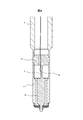
- FIG. 8 is an enlarged cross-sectional view of a portion including the pressure detection structure of the pressure sensor 1 according to the second embodiment of the present invention.
- the installation position of the pressure detection part 5 in the element installation part 3b differs.
- the pressure detection unit 5 including the pressure detection element 5 a is the pressure sensor in the axial direction of the pressure sensor 1, that is, when the pressure sensor 1 is attached to the engine.
- the center of the pressure detection unit 5 (pressure detection element 5a) in the insertion direction of 1 is installed at a position closer to the pressure transmission unit 3a than the center of the element installation unit 3b in that direction.
- the detection sensitivity of the combustion pressure of the engine by the pressure sensor 1 is further improved as compared with the first embodiment.
- Other structures are the same as those in the first embodiment.
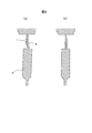
- FIG. 9 is a schematic diagram showing a deformed state of the element installation portion 3b at the time of pressure reception in the first embodiment and the second embodiment of the present invention.
- FIG. 9A shows a deformed state in the configuration of the first embodiment
- FIG. 9B shows a deformed state in the configuration of the present embodiment.
- the pressure detection unit 5 is disposed in the approximate center of the element installation unit 3 b in the axial direction of the pressure sensor 1.
- the pressure transmission portion 3a is inclined with respect to the axial direction. Therefore, in the flat surface on the side where the pressure detection unit 5 is installed among the two flat surfaces formed in the element installation unit 3b, the vicinity of the installation part of the pressure detection unit 5 is convex, and the pressure transmission unit 3a Deformation occurs in which the vicinity of the connecting portion is concave.
- the pressure transmission rod 3 is provided at a location located inside the engine with respect to the element installation portion 3b when the pressure sensor 1 is attached to the engine.
- the pressure transmission part 3a which transmits a pressure to the installation part 3b is provided.
- the pressure detection element 5a is such that the center of the pressure detection element 5a in the insertion direction of the pressure sensor 1 when the pressure sensor 1 is attached to the engine is closer to the pressure transmission part 3a than the center of the element installation part 3b. In place. Since it did in this way, the deformation
- the example in which the pressure transmission sensitivity is improved by making the length of the pressure transmission unit 3a the same as that of the first embodiment is described.
- the length may be made longer than that of the first embodiment, and the decrease in pressure detection sensitivity due to this may be compensated by the pressure detection sensitivity improvement effect according to this embodiment.
- the pressure detection unit 5 including the circuit unit 5b can be moved away from the combustion chamber of the engine, the temperature rise of the circuit unit 5b can be suppressed while maintaining the pressure detection sensitivity.
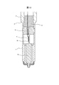
- FIG. 10 is an enlarged cross-sectional view of a portion including the pressure detection structure of the pressure sensor 1 according to the third embodiment of the present invention.
- the shape of the element installation part 3b differs. Specifically, in the structure shown in FIG. 10, the element installation portion 3b is provided on a flat installation surface 3d on which the pressure detection unit 5 including the pressure detection element 5a is installed, and on the opposite side of the installation surface 3d. And a cut surface 3e having a stepped portion 3f.
- the position of the step 3f on the cut surface 3e is more in the axial direction of the pressure sensor 1 than the position of the step formed at the boundary between the pressure transmitting unit 3a and the element installation unit 3b on the opposite installation surface 3d. Behind, that is, away from the combustion chamber of the engine. Thereby, the detection sensitivity of the combustion pressure of the engine by the pressure sensor 1 is further improved as compared with the first embodiment.
- Other structures are the same as those in the first embodiment.
- FIG. 11 is a schematic diagram illustrating a deformed state of the element installation portion 3b during pressure reception in the third embodiment of the present invention.
- the element installation portion 3b In the deformation state of the element installation portion 3b at the time of receiving pressure in the structure of the present embodiment, as shown in FIG. 11, the element installation portion 3b is deformed such that the installation surface 3d on which the pressure detection element 5a is installed is concave. .
- the element installation part 3b is thicker than the first embodiment to increase the rigidity, and the element installation part 3b is provided with a step part 3f on the cut surface 3e opposite to the installation surface 3d.
- the installation surface 3d is easily deformed into a recess.
- the pressure detection sensitivity of the pressure sensor 1 can be improved.
- the pressure transmission rod 3 is provided at a location located inside the engine with respect to the element installation portion 3b when the pressure sensor 1 is attached to the engine.
- the pressure transmission part 3a which transmits a pressure to the installation part 3b is provided.
- the element installation portion 3b has an installation surface 3d on which the pressure detection element 5a is installed, and a cut surface 3e provided on the opposite side of the installation surface 3d and having a step portion 3f. Since it did in this way, the pressure detection sensitivity of the pressure sensor 1 can be improved by applying the compression by bending to the pressure detection element 5a.
- the length of the pressure transmission part 3a can be made longer than that of the first embodiment, as in the second embodiment. That is, in the third embodiment of the present invention, the example in which the pressure transmission sensitivity is improved by making the length of the pressure transmission portion 3a the same as that of the first embodiment is shown. However, the length of the pressure transmission portion 3a is increased. It is good also as a structure which makes it longer than 1st Embodiment and compensates the fall of the pressure detection sensitivity by this with the pressure detection sensitivity improvement effect by this embodiment. In this way, since the pressure detection unit 5 including the circuit unit 5b can be moved away from the combustion chamber of the engine, the temperature rise of the circuit unit 5b can be suppressed while maintaining the pressure detection sensitivity.
- the installation position of the pressure detection unit 5 in the element installation unit 3b is the same as that in the first embodiment.
- the installation position is the same as that in the second embodiment. Also good. Thus, even if it is the structure which deform
- FIG. 12 is an enlarged cross-sectional view of a portion including the pressure detection structure of the pressure sensor 1 according to the fourth embodiment of the present invention.
- the heat conductive material 15 is added between the pressure detection part 5 and the contact part 9.
- the heat conductive material 15 include a heat conductive rubber, a resin material such as an epoxy resin, a silicone resin, and a urethane resin mixed with a heat conductive powder such as a metal powder or a ceramic powder, a heat conductive grease, or the like.
- the housing 6 and the high-rigidity portion 3c are softer.
- the heat conductive material 15 is filled between the inside of the housing 6 and the high rigidity portion 3c, and the circuit portion 5b of the pressure detection portion 5 is connected to the contact portion 9 via the element installation portion 3b and the high rigidity portion 3c. Improve heat dissipation.
- the pressure sensor 1 further includes the heat conductive material 15 disposed between the pressure detection unit 5 including the circuit unit 5b and the contact unit 9. Since it did in this way, the heat dissipation from the circuit part 5b can be improved, and the temperature rise of the circuit part 5b can be suppressed.
- the heat conductive material 15 is made of a material softer than the housing 6 and the high-rigidity portion 3c, the influence of stress due to deformation of the housing 6 is small. Therefore, the temperature rise of the circuit unit 5b can be suppressed without adversely affecting the sensor output.
- the example in which the heat conductive material 15 is filled up to the high-rigidity portion 3c is shown.
- the heat conductive material 15 is further provided around the element installation portion 3b.
- the pressure detection unit 5 may be covered.
- a structure in which the heat conductive material 15 does not contact the cover 4 is desirable so that heat inside the engine is not transmitted to the pressure detection unit 5 via the cover 4 and the heat conductive material 15. With such a configuration, the temperature rise of the pressure detector 5 can be further suppressed.
- the heat conductive material disposed between the pressure detection unit 5 and the contact unit 9 may have another shape. Below, the modification of a heat conductive material is demonstrated using FIG.
- FIG. 13 is a view showing a modification of the thermally conductive material in the pressure sensor 1.
- Fig.13 (a) it is good also as a structure which extended the highly rigid part 3c inside the housing
- FIG.13 (b) it is good also as a structure which expanded the inner side of the housing
- the material of the heat conductive materials 16 and 17 is the same as the heat conductive material 15 demonstrated in FIG.
Landscapes
- Physics & Mathematics (AREA)
- General Physics & Mathematics (AREA)
- Chemical & Material Sciences (AREA)
- Engineering & Computer Science (AREA)
- Analytical Chemistry (AREA)
- Combustion & Propulsion (AREA)
- Mechanical Engineering (AREA)
- General Engineering & Computer Science (AREA)
- Measuring Fluid Pressure (AREA)
- Combined Controls Of Internal Combustion Engines (AREA)
Abstract
エンジンの燃焼圧を検知する圧力センサは、前記圧力センサが前記エンジンに取り付けられたときに前記エンジンの筐体と直接的または間接的に接触する接触部と、前記燃焼圧を検知して圧力に対応した信号を出力する圧力検知部と、を備え、前記圧力検知部は、前記燃焼圧を検知して信号を出力する圧力検知素子と、前記圧力検知素子から得られた前記信号を前記圧力に対応した信号に変換する回路部とを有し、前記圧力検知部は、前記圧力センサが前記エンジンに取り付けられたときに前記接触部よりも前記エンジンの内側に位置する場所に設けられている。
Description
本発明は、圧力センサに関する。
従来、エンジンの燃焼圧を検知する圧力センサが知られている。特許文献1には、感知素子が取り付けられた感知構造と、感知素子から得られた信号を処理する電子回路とを備え、感知構造は燃焼エンジンの燃焼室の近位置に配置され、電子回路は感知構造から離されての燃焼エンジンの外側に配置された、圧力測定プラグが記載されている。
特許文献1の圧力測定プラグでは、感知素子と電子回路が離れているために、感知素子と電子回路を接続する配線において、外部からのノイズを受けやすく、検知精度が悪化するという問題がある。
本発明による圧力センサは、エンジンの燃焼圧を検知するものであって、前記圧力センサが前記エンジンに取り付けられたときに前記エンジンの筐体と直接的または間接的に接触する接触部と、前記燃焼圧を検知して圧力に対応した信号を出力する圧力検知部と、を備え、前記圧力検知部は、前記燃焼圧を検知して信号を出力する圧力検知素子と、前記圧力検知素子から得られた前記信号を前記圧力に対応した信号に変換する回路部とを有し、前記圧力検知部は、前記圧力センサが前記エンジンに取り付けられたときに前記接触部よりも前記エンジンの内側に位置する場所に設けられている。
本発明によれば、外部からのノイズに強く、検知精度を向上した圧力センサを提供することができる。
以下、本発明の実施形態を図面を用いて説明する。
(第1の実施形態)
本発明の第1の実施形態に係る圧力センサについて、図1~3を参照して説明する。図1は、本発明の一実施形態に係る圧力センサの外観図である。図2は、本発明の一実施形態に係る圧力センサの分解図である。図3は、本発明の一実施形態に係る圧力センサの断面図である。
本発明の第1の実施形態に係る圧力センサについて、図1~3を参照して説明する。図1は、本発明の一実施形態に係る圧力センサの外観図である。図2は、本発明の一実施形態に係る圧力センサの分解図である。図3は、本発明の一実施形態に係る圧力センサの断面図である。
圧力センサ1は、車両等の内燃機関であるエンジンに取り付けられ、エンジンの燃焼圧を検知してその燃焼圧に応じたセンサ出力を外部に出力する。図1に示すように、圧力センサ1は、ダイアフラム2、カバー4、筐体6、および端子部7を備えている。筐体6には、圧力センサ1をエンジンの筐体に固定するためのネジ部10と、圧力センサ1がエンジンに取り付けられたときにエンジンの筐体と接触する接触部9とが設けられている。
図2および図3に示すように、カバー4の内部には、圧力伝達ロッド3および圧力検知部5が収納されている。圧力検知部5と端子部7は、信号線8で接続されている。
ダイアフラム2は、圧力伝達ロッド3とカバー4に接して配置されている。この配置により、ダイアフラム2は、エンジンの燃焼圧を受けて変形することで圧力伝達ロッド3に圧縮力を与える機能と、エンジン内部の燃焼ガスがセンサ1内に侵入するのを防ぐ機能とを有する。
圧力伝達ロッド3には圧力検知部5が設置されている。圧力伝達ロッド3は、ダイアフラム2から受けた圧縮力に応じて圧力検知部5の設置位置を含む範囲内で歪を生じることにより、圧力検知部5にエンジンの燃焼圧を伝達する圧力伝達機構として作用する。圧力検知部5は、圧力伝達ロッド3の歪を検出することでエンジンの燃焼圧を検知し、その検知結果に応じた圧力信号を信号線8を介して端子部7に出力する。この圧力信号は、端子部7から圧力センサ1の外部にセンサ出力として出力される。なお、圧力検知部5から得られた圧力信号に対して出力調整などの信号処理を行うことでセンサ出力を生成し、外部へと出力する回路を端子部7に設けてもよい。
図4は、圧力検知部5の概略構成を示す図である。図4に示すように、圧力検知部5には、たとえば中央部分に設けられた圧力検知素子5aと、その周囲に設けられた回路部5bとが、同一の基板上に形成されている。圧力検知素子5aは、たとえば歪ゲージ等を用いて構成されており、エンジンの燃焼圧に応じて圧力伝達ロッド3に生じる歪量を検出することでエンジンの燃焼圧を検知する。圧力検知素子5aは、検出した歪量すなわちエンジンの燃焼圧に応じた信号を回路部5bに出力する。回路部5bは、圧力検知素子5aから得られた信号に対して処理の信号処理を行い、センサ出力に対応する圧力信号に変換して端子部7に出力する。回路部5bは、圧力検知素子5aから得られた微弱な信号をアナログ増幅する機能や、圧力検知素子5aから得られた微弱な信号をデジタル変換する機能を有する。さらに、周囲の温度を検知して温度補正を行う機能を回路部5bが有してもよい。圧力検知部5では、回路部5bの近傍に圧力検知素子5aがあるため、回路部5bに内蔵した温度センサを用いて、圧力検知素子5aからの信号に対して温度補正を行うことができる。そのため、安価な構成で温度補正を実現できる。
本実施形態の圧力センサ1では、上記のように、圧力検知部5において圧力検知素子5aと回路部5bを同一基板上に形成している。そのため、圧力検知素子5aと回路部5bとを接続する配線長が大幅に短縮され、その結果、外部からのノイズの影響を低減できる。なお、本実施形態では圧力検知素子5aと回路部5bを同一基板上に形成した構成を示したが、ノイズの影響を十分に低減できる程度の近傍であれば、これらが別々の基板上に分離して配置されていてもよい。
ここで、圧力検知部5は、圧力センサ1がエンジンに取り付けられたときに接触部9よりもエンジンの内側に位置する場所に設けられている。回路部5bは一般に圧力検知素子5aよりも耐熱性が低いため、圧力検知素子5aの近傍に回路部5bを配置するためには、圧力センサ1において回路部5bを十分に放熱できる構造が必要となる。本実施形態では前述のように、圧力センサ1がエンジンに取り付けられたときに接触部9がエンジンの筐体と接触することで、回路部5bの放熱構造を実現している。すなわち、接触部9は、圧力伝達ロッド3や圧力検知部5により構成される圧力検知構造の近傍に配置されており、この圧力検知構造の熱を熱接触によりエンジンの筐体に放熱する放熱機能を有する。また、接触部9は、エンジンの筐体と密着することでエンジン内部の高温の燃焼ガスを遮蔽し、燃焼ガスが接触部9より圧力センサ1の後端側へと侵入するのを抑制する遮蔽機能を有する。これらの機能を接触部9が有することにより、耐熱温度が比較的低い回路部5bの温度上昇を抑制することができる。なお、回路部5bの温度上昇を十分に抑制できるのであれば、上記の放熱機能と遮蔽機能のいずれか一方のみを接触部9が有していてもよい。また、放熱機能や遮蔽機能を十分に発揮できる限り、接触部9とエンジンの筐体との接触は直接的であってもよく、あるいは他の部材を介した間接的なものであってもよい。
図5は、本発明の第1の実施形態における圧力センサ1の圧力検知構造を含む部分の拡大断面図である。図5に示すように、圧力伝達ロッド3は、圧力伝達部3a、素子設置部3b、高剛性部3cを備えている。
圧力伝達部3aは、ダイアフラム2と接しており、圧力センサ1がエンジンに取り付けられたときに素子設置部3bや高剛性部3cよりもエンジンの内側に位置する場所に設けられている。圧力伝達部3aは、ダイアフラム2から受けた圧縮力を素子設置部3bに伝達する。
素子設置部3bは、高剛性部3cよりも低い剛性を有しており、圧力伝達部3aから伝達された圧縮力に応じて歪を生じる部分である。素子設置部3bには、圧力伝達部3aの一部をカットした形状の平坦面が形成されており、この平坦面に圧力検知部5が固定されている。これにより、素子設置部3bにおける圧力検知素子5aの設置部分の歪量が圧力検知素子5aにより検知され、その歪量に応じたエンジンの燃焼圧が検出される。また、素子設置部3bには、圧力検知部5が固定される面の反対側にも、圧力伝達部3aの一部をカットした形状の平坦面が形成されている。これにより、圧力センサ1の軸方向、すなわち圧力センサ1をエンジンに取り付けるときの圧力センサ1の挿入方向について、この方向に対して垂直な面の断面積を小さくし、素子設置部3bの剛性を相対的に下げている。その結果、素子設置部3bの歪量を増大させ、検知感度を向上させることができる。
高剛性部3cは、圧力センサ1の軸方向に対して垂直な面の断面積が素子設置部3bより大きく設定されており、素子設置部3bよりも高い剛性を有する。これにより、高剛性部3cは、圧力伝達部3aから伝達された圧縮力を受け止めて、素子設置部3bにおける歪量を最大化する機能を有する。
なお、高剛性部3cは、素子設置部3bと接触部9との間に配置されており、圧力センサ1がエンジンに取り付けられると、接触部9よりもエンジンの内側で素子設置部3bに接続する。そのため、圧力センサ1をエンジンに固定した際に接触部9を起点に発生する圧力センサ1の変形を高剛性部3cにおいて減衰させ、素子設置部3bにおける歪発生を抑制することができる。その結果、圧力センサ1の取り付け時に生じるセンサ出力の変動を抑制することができる。なお、図3や図5では、高剛性部3cが筐体6とカバー4の間に配置されており、高剛性部3cが筐体6に直接接触している構成を示しているが、高剛性部3cを筐体6に間接的に接触させた構成としてもよい。たとえば、筐体6とカバー4を溶接等で接合し、カバー4に高剛性部3cを接触して配置することで、高剛性部3cがカバー4を介して筐体6に接続しているような構成でもよい。
高剛性部3cと接触部9との間には、筐体6の一部である応力吸収部11が設けられている。応力吸収部11は、接触部9がエンジンの筐体と接触することで生じる変形応力を吸収するための部分である。応力吸収部11は、高剛性部3cに比べて剛性が低いため、圧力センサ1をエンジンに固定した際に接触部9を起点に発生する圧力センサ1の変形が高剛性部3cに与える応力を低減する応力低減機能を有する。
図6は、応力吸収部11の長さLに対する、圧力センサ1の固定時に発生する素子設置部3bの歪量、および、エンジン燃焼時の圧力検知部5における回路部5bの温度の関係の一例を示す図である。図6において、グラフ61は素子設置部3bの歪量を表し、グラフ62は回路部5bの温度を表している。グラフ61に示すように、応力吸収部11の長さLが長くなる程、上記の応力低減機能で高い効果が得られるため、素子設置部3bの歪量を低減させることができる。しかし一方で、グラフ62に示すように、応力吸収部11の長さLが長くなる程、圧力検知部5から接触部9までの熱伝導性が低下するため、回路部5bの温度が上昇する。すなわち、応力吸収部11による応力低減機能の効果は、圧力検知部5の放熱性に対してトレードオフの関係にある。
図6において、圧力センサ1の固定時に発生する素子設置部3bの歪量は、グラフ61に示すように、応力吸収部11の長さLが3mm以上ではほぼ飽和している。一方、回路部5bの温度は、グラフ62に示すように、応力吸収部11の長さLに比例して上昇している。そのため、応力吸収部11の長さLが約3mmのときの回路部5bの温度が耐熱温度以下となるように圧力検知部5を設計すれば、応力吸収部11による応力低減機能の効果を最大限に発揮させつつ、必要な放熱性を確保できる。たとえば、回路部5bの耐熱温度を150℃に設計することで、応力吸収部11の長さLを3mmとして素子設置部3bの歪量を抑制し、圧力センサ1の取り付け時に生じるセンサ出力の変動を最小限とすることができる。なお、必要なセンサ出力が得られれば、回路部5bの耐熱温度はなるべく低い方がコスト上有利であるため、上記の長さLの3mmや耐熱温度の150℃は一例であり、これに限らない。
以上説明したように、圧力センサ1において、圧力伝達部3a、素子設置部3bおよび高剛性部3cは、圧力伝達ロッド3として一体形成されている。また、高剛性部3cと応力吸収部11は溶接等によって一体化されている。さらに、応力吸収部11は接触部9と連続的に一体形成されている。このような構成により、素子設置部3bから高剛性部3cおよび応力吸収部11を経由して接触部9までを熱的に連続的に接続し、素子設置部3bに設置された圧力検知部5における熱を、圧力センサ1が取り付けられたエンジンの筐体へと効率的に放熱することができる。これにより、耐熱温度の低い回路部5bであっても、回路部5bの温度上昇を抑制して耐熱温度以下とすることができる。なお、素子設置部3b、高剛性部3c、応力吸収部11、接触部9の相互の接続には、熱的に連続的に接続できるものであれば、たとえば一体形成、溶接、半田接合、ろう接合、圧入、焼き嵌めなど、任意の接続方法を用いることができる。また、応力吸収部11を設けずに、高剛性部3cを接触部9に直接接触させてもよい。
さらに、圧力検知部5における熱を効率的に放熱するためには、圧力検知部5から接触部9までの伝熱距離が短い方が望ましい。本実施形態による圧力センサ1の構成では、圧力検知部5から接触部9まで迂回することなく熱が伝わる経路が形成されているため、効率的な放熱が可能である。
以上説明したように、本実施形態に係る圧力センサ1によれば、圧力検知部5において回路部5bの温度上昇を抑制しつつ、圧力検知素子5aと回路部5bとを接続する配線長が大幅に短縮される。そのため、外部からのノイズの影響を低減できる。
以上説明した本発明の第1の実施形態によれば、以下の作用効果を奏する。
(1)エンジンの燃焼圧を検知する圧力センサ1は、圧力センサ1がエンジンに取り付けられたときにエンジンの筐体と直接的または間接的に接触する接触部9と、エンジンの燃焼圧を検知して圧力センサ1の外部にセンサ出力を出力する圧力検知部5と、を備える。圧力検知部5は、エンジンの燃焼圧を検知して信号を出力する圧力検知素子5aと、圧力検知素子5aから得られた信号をセンサ出力に対応する圧力信号に変換する回路部5bとを有する。圧力検知部5は、圧力センサ1がエンジンに取り付けられたときに接触部9よりもエンジンの内側に位置する場所に設けられている。このようにしたので、外部からのノイズに強く、検知精度を向上した圧力センサを提供することができる。
(2)圧力センサ1は、圧力検知素子5aにエンジンの燃焼圧を伝達する圧力伝達機構である圧力伝達ロッド3をさらに備える。圧力伝達ロッド3の少なくとも一部は、圧力センサ1がエンジンに取り付けられたときに回路部5bよりもエンジンの内側に位置する場所に設けられている。このようにしたので、回路部5bの温度上昇をなるべく抑制しつつ、圧力検知素子5aにおいてエンジンの燃焼圧を検知することができる。
(3)圧力センサ1は、接触部9と圧力検知部5との間に、接触部9がエンジンの筐体と接触することで生じる変形応力を吸収するための応力吸収部11をさらに備える。このようにしたので、圧力センサ1の固定時に発生する素子設置部3bの歪量を低減し、センサ出力の変動を抑制することができる。
(4)圧力伝達ロッド3は、圧力検知素子5aが設置された素子設置部3bと、素子設置部3bと応力吸収部11との間、または素子設置部3bと接触部9との間に配置され、素子設置部3bよりも高い剛性を有する高剛性部3cとを備える。このようにしたので、素子設置部3bにおける歪量を増大させ、圧力センサ1によるエンジンの燃焼圧の検知感度を向上させることができる。
(接触部の変形例)
なお、以上説明した本発明の第1の実施形態では、圧力センサ1がエンジンに取り付けられたときにエンジンの筐体と接触する接触部の形状として、圧力センサ1の筐体6に段差を設けて形成した接触部9の例を示したが、エンジンの筐体との接触部を他の形状としてもよい。以下では図7を用いて、接触部の変形例を説明する。
なお、以上説明した本発明の第1の実施形態では、圧力センサ1がエンジンに取り付けられたときにエンジンの筐体と接触する接触部の形状として、圧力センサ1の筐体6に段差を設けて形成した接触部9の例を示したが、エンジンの筐体との接触部を他の形状としてもよい。以下では図7を用いて、接触部の変形例を説明する。
図7は、圧力センサ1における接触部の変形例を示す図である。図7(a)は、圧力センサ1の接触部として、筐体6の側面に筐体6とは別部材で形成された接触部材12を設けた例を示している。接触部材12は、金属などの熱伝導性弾性材料で形成され、筐体6の側面に、ろう付け、接着剤、圧入、カシメ、溶接等で固定される。接触部材12の外径は、エンジンの筐体に設けられた圧力センサ1の導入孔の径よりも僅かに大きく設定される。圧力センサ1をエンジンに取り付ける際には、接触部材12の弾性によりエンジンの筐体への接触が得られる。
また、圧力センサ1の接触部として、図7(b)に示すようなOリング13を圧力センサ1の筐体6の側面に設けてもよい。圧力センサ1がエンジンに取り付けられた状態では、Oリング13がエンジンの筐体と密着することで、エンジン内の高温の燃焼ガスがOリング13よりも圧力センサ1の後端側へと侵入することが防止される。これにより、圧力検知部5における回路部5bの温度上昇を抑制することができる。
また、圧力センサ1の接触部として、図7(c)に示すような熱伝導性弾性体14を圧力センサ1の筐体6の側面に設けてもよい。熱伝導性弾性体14は、たとえば熱伝導ゴムや、金属粉やセラミックス粉等を混合した樹脂材料など、熱伝導性が高い弾性材料で形成され、筐体6の側面に、接着剤、圧入、インサート成形、溶接等で固定される。熱伝導性弾性体14の外径は、エンジンの筐体に設けられた圧力センサ1の導入孔の径より僅かに大きく設定される。圧力センサ1をエンジンに取り付ける際には、熱伝導性弾性体14の弾性によりエンジンの筐体への接触が得られる。
(第2の実施形態)
次に本発明の第2の実施形態について説明する。本実施形態では、第1の実施形態で説明した圧力センサ1において、さらに圧力検知感度を向上させた例を説明する。
次に本発明の第2の実施形態について説明する。本実施形態では、第1の実施形態で説明した圧力センサ1において、さらに圧力検知感度を向上させた例を説明する。
図8は、本発明の第2の実施形態における圧力センサ1の圧力検知構造を含む部分の拡大断面図である。本実施形態では、図5で説明した第1の実施形態の構造と比較して、素子設置部3bにおける圧力検知部5の設置位置が異なっている。具体的には、図8に示した構造では、圧力検知素子5aを含む圧力検知部5は、素子設置部3bにおいて、圧力センサ1の軸方向、すなわち圧力センサ1をエンジンに取り付けるときの圧力センサ1の挿入方向における圧力検知部5(圧力検知素子5a)の中心が、当該方向における素子設置部3bの中心よりも圧力伝達部3aに近い位置に設置されている。これにより、圧力センサ1によるエンジンの燃焼圧の検知感度を第1の実施形態よりもさらに向上させている。なお、それ以外の構造については、第1の実施形態と同一である。
本実施形態において圧力センサ1の圧力検知感度が向上する理由を、図9を用いて以下に説明する。図9は、本発明の第1の実施形態および第2の実施形態における受圧時の素子設置部3bの変形状態を示した模式図である。図9(a)は第1の実施形態の構成での変形状態を示し、図9(b)は本実施形態の構成での変形状態を示している。
第1の実施形態では、図5に示したように、圧力センサ1の軸方向において圧力検知部5が素子設置部3bの略中央に配置されている。このような構造における受圧時の素子設置部3bの変形状態では、図9(a)に示すように、圧力伝達部3aが軸方向に対して傾斜する。そのため、素子設置部3bに形成された二つの平坦面のうち、圧力検知部5が設置されている側の平坦面において、圧力検知部5の設置部分付近が凸となり、圧力伝達部3aとの接続部分付近が凹となるような変形が生じる。これは、素子設置部3bの一方の平坦面に圧力検知部5を設置することで、当該設置部分の剛性が相対的に高くなって圧縮されにくくなったことに起因する。これにより、本来は圧力伝達部3aから伝達された圧縮力を受けて軸方向に圧縮されるべき素子設置部3bが、上記のような形状に変形されることで圧縮が緩和されてしまい、圧力検知素子5aにおいて生じる歪量が減少する。その結果、圧力センサ1の圧力検知感度が低下してしまうことがある。
一方、本実施形態の構造における受圧時の素子設置部3bの変形状態では、図9(b)に示すように、圧力伝達部3aが軸方向に対して傾斜するような変形が抑制されている。これは、素子設置部3bにおける圧力検知部5の設置位置を前述のようにすることで、図9(a)では凹に変形している圧力伝達部3aとの接続部分付近に圧力検知部5が設置されており、そのため上記のような変形を抑制していることに起因する。その結果、第1の実施形態と比較して、圧力センサ1の圧力検知感度を向上させることができる。
以上説明した本発明の第2の実施形態によれば、圧力伝達ロッド3は、圧力センサ1がエンジンに取り付けられたときに素子設置部3bよりもエンジンの内側に位置する場所に設けられ、素子設置部3bに圧力を伝達する圧力伝達部3aを備える。圧力検知素子5aは、素子設置部3bにおいて、圧力センサ1をエンジンに取り付けるときの圧力センサ1の挿入方向における圧力検知素子5aの中心が、素子設置部3bの中心よりも圧力伝達部3aに近い位置に設置されている。このようにしたので、圧力伝達部3aが傾斜するような変形が抑制され、圧力センサ1の圧力検知感度を向上できる。
なお、以上説明した本発明の第2の実施形態では、圧力伝達部3aの長さを第1の実施形態と同一にして圧力検知感度を向上させた例を示したが、圧力伝達部3aの長さを第1の実施形態よりも長くして、これによる圧力検知感度の低下分を本実施形態による圧力検知感度向上効果で補う構成としてもよい。このようにすれば、回路部5bを含む圧力検知部5をエンジンの燃焼室から遠ざけることができるため、圧力検知感度を維持しつつ回路部5bの温度上昇を抑制することができる。
(第3の実施形態)
次に本発明の第3の実施形態について説明する。本実施形態では、第1の実施形態で説明した圧力センサ1において、第2の実施形態で説明したのとは別の方法により、さらに圧力検知感度を向上させた例を説明する。
次に本発明の第3の実施形態について説明する。本実施形態では、第1の実施形態で説明した圧力センサ1において、第2の実施形態で説明したのとは別の方法により、さらに圧力検知感度を向上させた例を説明する。
図10は、本発明の第3の実施形態における圧力センサ1の圧力検知構造を含む部分の拡大断面図である。本実施形態では、図5で説明した第1の実施形態の構造と比較して、素子設置部3bの形状が異なっている。具体的には、図10に示した構造では、素子設置部3bは、圧力検知素子5aを含む圧力検知部5が設置された平坦な設置面3dと、この設置面3dの反対側に設けられて段差部3fを有するカット面3eとを有している。このカット面3eにおける段差部3fの位置は、反対側の設置面3dにおいて圧力伝達部3aと素子設置部3bとの境界部分に形成されている段差の位置よりも、圧力センサ1の軸方向で後方、すなわちエンジンの燃焼室から離れている。これにより、圧力センサ1によるエンジンの燃焼圧の検知感度を第1の実施形態よりもさらに向上させている。なお、それ以外の構造については、第1の実施形態と同一である。
本実施形態において圧力センサ1の圧力検知感度が向上する理由を、図11を用いて以下に説明する。図11は、本発明の第3の実施形態における受圧時の素子設置部3bの変形状態を示した模式図である。
本実施形態の構造における受圧時の素子設置部3bの変形状態では、図11に示すように、素子設置部3bにおいて圧力検知素子5aが設置された設置面3dが凹となるような変形が生じる。これは、第1の実施形態と比較して素子設置部3bを肉厚形状にして剛性を高めると共に、素子設置部3bにおいて設置面3dと反対側のカット面3eに段差部3fを設けることで、設置面3dが凹に変形しやすくなったことに起因する。このように、圧力検知部5を設置した面が凹になるように変形することで、圧力センサ1の軸方向の圧縮に加えて、曲げによる圧縮が圧力検知素子5aに印加される。その結果、第1の実施形態と比較して、圧力センサ1の圧力検知感度を向上させることができる。
以上説明した本発明の第3の実施形態によれば、圧力伝達ロッド3は、圧力センサ1がエンジンに取り付けられたときに素子設置部3bよりもエンジンの内側に位置する場所に設けられ、素子設置部3bに圧力を伝達する圧力伝達部3aを備える。素子設置部3bは、圧力検知素子5aが設置された設置面3dと、設置面3dの反対側に設けられて段差部3fを有するカット面3eとを有する。このようにしたので、曲げによる圧縮を圧力検知素子5aに印加して、圧力センサ1の圧力検知感度を向上できる。
なお、以上説明した本発明の第3の実施形態でも、第2の実施形態と同様に、圧力伝達部3aの長さを第1の実施形態よりも長くした構成とすることができる。すなわち、本発明の第3の実施形態では、圧力伝達部3aの長さを第1の実施形態と同一にして圧力検知感度を向上させた例を示したが、圧力伝達部3aの長さを第1の実施形態よりも長くして、これによる圧力検知感度の低下分を本実施形態による圧力検知感度向上効果で補う構成としてもよい。このようにすれば、回路部5bを含む圧力検知部5をエンジンの燃焼室から遠ざけることができるため、圧力検知感度を維持しつつ回路部5bの温度上昇を抑制することができる。
また、以上説明した本発明の第3の実施形態では、素子設置部3bにおける圧力検知部5の設置位置を第1の実施形態と同様としたが、第2の実施形態と同様の設置位置としてもよい。このようにして第2の実施形態を変形した構成であっても、上記で説明したのと同様の効果が得られる。
(第4の実施形態)
次に本発明の第4の実施形態について説明する。本実施形態では、第1の実施形態で説明した圧力センサ1において、圧力検知回路の温度上昇をさらに抑制した例を説明する。
次に本発明の第4の実施形態について説明する。本実施形態では、第1の実施形態で説明した圧力センサ1において、圧力検知回路の温度上昇をさらに抑制した例を説明する。
図12は、本発明の第4の実施形態における圧力センサ1の圧力検知構造を含む部分の拡大断面図である。本実施形態では、図5で説明した第1の実施形態の構造と比較して、圧力検知部5と接触部9との間に、熱伝導性材料15が追加されている。熱伝導性材料15は、たとえば、熱伝導性ゴムや、エポキシ樹脂、シリコーン樹脂、ウレタン樹脂等の樹脂材料に金属粉やセラミックス粉などの熱伝導性粉末を混合したものや、熱伝導性グリースなど、筐体6および高剛性部3cより柔らかいものからなる。熱伝導性材料15は、筐体6の内側と高剛性部3cとの間に充填され、圧力検知部5の回路部5bから素子設置部3bおよび高剛性部3cを介した接触部9への放熱性を向上させる。
以上説明した本発明の第4の実施形態によれば、圧力センサ1は、回路部5bを含む圧力検知部5と接触部9との間に配置された熱伝導性材料15をさらに備える。このようにしたので、回路部5bからの放熱性を向上し、回路部5bの温度上昇を抑制することができる。また、熱伝導性材料15は筐体6および高剛性部3cより柔らかいものからなるので、筐体6の変形などによる応力の影響が小さい。そのため、センサ出力に悪影響を及ぼすことなく、回路部5bの温度上昇を抑制することができる。
なお、以上説明した本発明の第3の実施形態では、熱伝導性材料15が高剛性部3cまで充填されている例を示したが、熱伝導性材料15がさらに素子設置部3bの周囲にも充填されており、圧力検知部5を覆うような構成であってもよい。このとき、エンジン内部の熱がカバー4および熱伝導性材料15を介して圧力検知部5に伝達されないように、熱伝導性材料15がカバー4に接触しない構造が望ましい。このような構成により、圧力検知部5の温度上昇をさらに抑制することができる。
(熱伝導性材料の変形例)
なお、以上説明した本発明の第4の実施形態において、圧力検知部5と接触部9との間に配置された熱伝導性材料を他の形状としてもよい。以下では図13を用いて、熱伝導性材料の変形例を説明する。
なお、以上説明した本発明の第4の実施形態において、圧力検知部5と接触部9との間に配置された熱伝導性材料を他の形状としてもよい。以下では図13を用いて、熱伝導性材料の変形例を説明する。
図13は、圧力センサ1における熱伝導性材料の変形例を示す図である。図13(a)に示すように、高剛性部3cを筐体6の内側に延長し、これらの間に熱伝導性材料16を充填した構成としてもよい。また、図13(b)に示すように、筐体6の内側を拡張し、これと高剛性部3cとの間に熱伝導性材料17を充填した構成としてもよい。なお、熱伝導性材料16、17の材質は、図12で説明した熱伝導性材料15と同一である。
なお、以上説明した各実施形態や各種変形例はあくまで一例であり、発明の特徴が損なわれない限り、本発明はこれらの内容に限定されるものではない。また、上記では種々の実施形態や変形例を説明したが、本発明はこれらの内容に限定されるものではない。本発明の技術的思想の範囲内で考えられるその他の態様も本発明の範囲内に含まれる。
次の優先権基礎出願の開示内容は引用文としてここに組み込まれる。
日本国特許出願2017年第035081号(2017年2月27日出願)
日本国特許出願2017年第035081号(2017年2月27日出願)
1 圧力センサ
2 ダイアフラム
3 圧力伝達ロッド
3a 圧力伝達部
3b 素子設置部
3c 高剛性部
4 カバー
5 圧力検知部
5a 圧力検知素子
5b 回路部
6 筐体
7 端子部
8 信号線
9 接触部
10 ネジ部
11 応力吸収部
12 接触部材
13 Oリング
14 熱伝導性弾性体
15、16、17 熱伝導性材料
2 ダイアフラム
3 圧力伝達ロッド
3a 圧力伝達部
3b 素子設置部
3c 高剛性部
4 カバー
5 圧力検知部
5a 圧力検知素子
5b 回路部
6 筐体
7 端子部
8 信号線
9 接触部
10 ネジ部
11 応力吸収部
12 接触部材
13 Oリング
14 熱伝導性弾性体
15、16、17 熱伝導性材料
Claims (8)
- エンジンの燃焼圧を検知する圧力センサであって、
前記圧力センサが前記エンジンに取り付けられたときに前記エンジンの筐体と直接的または間接的に接触する接触部と、
前記燃焼圧を検知して圧力に対応した信号を出力する圧力検知部と、を備え、
前記圧力検知部は、前記燃焼圧を検知して信号を出力する圧力検知素子と、前記圧力検知素子から得られた前記信号を前記圧力に対応した信号に変換する回路部とを有し、
前記圧力検知部は、前記圧力センサが前記エンジンに取り付けられたときに前記接触部よりも前記エンジンの内側に位置する場所に設けられている圧力センサ。 - 請求項1に記載の圧力センサにおいて、
前記圧力検知素子に前記燃焼圧を伝達する圧力伝達機構をさらに備え、
前記圧力伝達機構の少なくとも一部は、前記圧力センサが前記エンジンに取り付けられたときに前記回路部よりも前記エンジンの内側に位置する場所に設けられている圧力センサ。 - 請求項2に記載の圧力センサにおいて、
前記接触部と前記圧力検知部との間に、前記接触部が前記エンジンの筐体と接触することで生じる変形応力を吸収するための応力吸収部をさらに備える圧力センサ。 - 請求項3に記載の圧力センサにおいて、
前記圧力伝達機構は、
前記圧力検知素子が設置された素子設置部と、
前記素子設置部と前記応力吸収部との間に配置され、前記素子設置部よりも高い剛性を有する高剛性部とを備える圧力センサ。 - 請求項2に記載の圧力センサにおいて、
前記圧力伝達機構は、
前記圧力検知素子が設置された素子設置部と、
前記素子設置部と前記接触部との間に配置され、前記素子設置部よりも高い剛性を有する高剛性部とを備える圧力センサ。 - 請求項1~5のいずれか一項に記載の圧力センサにおいて、
前記回路部と前記接触部との間に配置された熱伝導性材料をさらに備える圧力センサ。 - 請求項4または5に記載の圧力センサにおいて、
前記圧力伝達機構は、前記圧力センサが前記エンジンに取り付けられたときに前記素子設置部よりも前記エンジンの内側に位置する場所に設けられ、前記素子設置部に圧力を伝達する圧力伝達部をさらに備え、
前記圧力検知素子は、前記素子設置部において、前記圧力センサを前記エンジンに取り付けるときの前記圧力センサの挿入方向における前記圧力検知素子の中心が、前記素子設置部の中心よりも前記圧力伝達部に近い位置に設置されている圧力センサ。 - 請求項4または5に記載の圧力センサにおいて、
前記圧力伝達機構は、前記圧力センサが前記エンジンに取り付けられたときに前記素子設置部よりも前記エンジンの内側に位置する場所に設けられ、前記素子設置部に圧力を伝達する圧力伝達部をさらに備え、
前記素子設置部は、前記圧力検知素子が設置された設置面と、前記設置面の反対側に設けられて段差部を有するカット面とを備える圧力センサ。
Priority Applications (2)
| Application Number | Priority Date | Filing Date | Title |
|---|---|---|---|
| US16/487,737 US11262266B2 (en) | 2017-02-27 | 2017-11-17 | Pressure sensor |
| DE112017006830.4T DE112017006830B4 (de) | 2017-02-27 | 2017-11-17 | Drucksensor |
Applications Claiming Priority (2)
| Application Number | Priority Date | Filing Date | Title |
|---|---|---|---|
| JP2017035081A JP6374550B1 (ja) | 2017-02-27 | 2017-02-27 | 圧力センサ |
| JP2017-035081 | 2017-02-27 |
Publications (1)
| Publication Number | Publication Date |
|---|---|
| WO2018154883A1 true WO2018154883A1 (ja) | 2018-08-30 |
Family
ID=63165961
Family Applications (1)
| Application Number | Title | Priority Date | Filing Date |
|---|---|---|---|
| PCT/JP2017/041500 Ceased WO2018154883A1 (ja) | 2017-02-27 | 2017-11-17 | 圧力センサ |
Country Status (4)
| Country | Link |
|---|---|
| US (1) | US11262266B2 (ja) |
| JP (1) | JP6374550B1 (ja) |
| DE (1) | DE112017006830B4 (ja) |
| WO (1) | WO2018154883A1 (ja) |
Families Citing this family (1)
| Publication number | Priority date | Publication date | Assignee | Title |
|---|---|---|---|---|
| CN116122961A (zh) * | 2022-11-23 | 2023-05-16 | 沪东重机有限公司 | 一种用于柴油机气缸内燃烧压力的监测装置 |
Citations (3)
| Publication number | Priority date | Publication date | Assignee | Title |
|---|---|---|---|---|
| JPH08136384A (ja) * | 1994-11-07 | 1996-05-31 | Matsushita Electric Ind Co Ltd | 燃焼圧センサ |
| JP3365028B2 (ja) * | 1994-03-14 | 2003-01-08 | 株式会社デンソー | 圧力検出装置 |
| JP4742593B2 (ja) * | 2005-01-19 | 2011-08-10 | 株式会社デンソー | 圧力検出装置の製造方法 |
Family Cites Families (16)
| Publication number | Priority date | Publication date | Assignee | Title |
|---|---|---|---|---|
| JPS6064559U (ja) | 1983-10-11 | 1985-05-08 | 日電アネルバ株式会社 | 放電トリガ− |
| JPH035081A (ja) | 1989-05-31 | 1991-01-10 | Brother Ind Ltd | プラズマ切断装置 |
| DE4103705A1 (de) * | 1990-07-18 | 1992-01-23 | Bosch Gmbh Robert | Druckgeber zur druckerfassung im brennraum von brennkraftmaschinen |
| DE4103704A1 (de) * | 1990-07-18 | 1992-01-23 | Bosch Gmbh Robert | Druckgeber zur druckerfassung im brennraum von brennkraftmaschinen |
| DE4106102A1 (de) * | 1991-02-27 | 1992-09-03 | Bosch Gmbh Robert | Druckgeber zur druckerfassung im brennraum von brennkraftmaschinen |
| DE19509188B4 (de) | 1994-03-14 | 2004-04-29 | Denso Corp., Kariya | Druckdetektor |
| JPH08261857A (ja) * | 1995-03-27 | 1996-10-11 | Matsushita Electric Ind Co Ltd | 圧力センサ |
| CA2162201A1 (en) | 1994-11-07 | 1996-05-08 | Matsushita Electric Industrial Co., Ltd. | Combustion pressure sensor and fabrication method thereof |
| JP4848904B2 (ja) * | 2006-09-13 | 2011-12-28 | 株式会社デンソー | 圧力センサ |
| JP5034394B2 (ja) * | 2006-09-13 | 2012-09-26 | 株式会社デンソー | 圧力センサ |
| JP5067138B2 (ja) | 2007-11-20 | 2012-11-07 | 株式会社デンソー | 圧力センサ |
| EP2138820B1 (en) * | 2008-06-25 | 2016-09-21 | Sensata Technologies, Inc. | A piezoresistive pressure-measuring plug for a combustion engine |
| JP5783566B2 (ja) * | 2010-10-20 | 2015-09-24 | センサータ テクノロジーズ インコーポレーテッド | 燃焼機関用の圧力測定プラグ |
| EP2781903B1 (en) * | 2013-03-20 | 2016-05-25 | Sensata Technologies, Inc. | A measuring plug and method for assembling a measuring plug |
| EP2808665B1 (en) * | 2013-05-28 | 2019-02-20 | Sensata Technologies, Inc. | A measuring plug |
| JP6580526B2 (ja) * | 2016-06-27 | 2019-09-25 | 日立オートモティブシステムズ株式会社 | 圧力センサ |
-
2017
- 2017-02-27 JP JP2017035081A patent/JP6374550B1/ja active Active
- 2017-11-17 DE DE112017006830.4T patent/DE112017006830B4/de active Active
- 2017-11-17 US US16/487,737 patent/US11262266B2/en active Active
- 2017-11-17 WO PCT/JP2017/041500 patent/WO2018154883A1/ja not_active Ceased
Patent Citations (3)
| Publication number | Priority date | Publication date | Assignee | Title |
|---|---|---|---|---|
| JP3365028B2 (ja) * | 1994-03-14 | 2003-01-08 | 株式会社デンソー | 圧力検出装置 |
| JPH08136384A (ja) * | 1994-11-07 | 1996-05-31 | Matsushita Electric Ind Co Ltd | 燃焼圧センサ |
| JP4742593B2 (ja) * | 2005-01-19 | 2011-08-10 | 株式会社デンソー | 圧力検出装置の製造方法 |
Also Published As
| Publication number | Publication date |
|---|---|
| JP6374550B1 (ja) | 2018-08-15 |
| JP2018141672A (ja) | 2018-09-13 |
| US20190376866A1 (en) | 2019-12-12 |
| US11262266B2 (en) | 2022-03-01 |
| DE112017006830T5 (de) | 2019-10-02 |
| DE112017006830B4 (de) | 2025-02-13 |
Similar Documents
| Publication | Publication Date | Title |
|---|---|---|
| JP4848904B2 (ja) | 圧力センサ | |
| US7404328B2 (en) | Pressure sensor | |
| US20050193826A1 (en) | Pressure sensor | |
| KR20130124387A (ko) | 연소 압력센서 장착 글로 플러그 | |
| JP2009186209A (ja) | 圧力センサ | |
| JP2009097926A (ja) | 圧力センサおよびその取付構造 | |
| JP6056562B2 (ja) | 圧力センサおよびその製造方法 | |
| US7536916B2 (en) | Pressure sensor | |
| US20090126472A1 (en) | Combustion pressure sensor for internal combustion engine | |
| JP6374550B1 (ja) | 圧力センサ | |
| JP4434299B2 (ja) | 燃焼圧センサ | |
| JP5141202B2 (ja) | 圧力センサの取付構造 | |
| JP4922822B2 (ja) | 燃焼圧センサ | |
| JP2006250614A (ja) | 圧力検出装置 | |
| US10048153B2 (en) | Pressure sensor including variable member having rear end connected to housing at a predetermined axial position | |
| JP4760590B2 (ja) | 温度検出素子 | |
| JP6554979B2 (ja) | 圧力センサ | |
| JP2019060626A (ja) | 圧力検知装置およびその組立方法 | |
| JP2010249675A (ja) | 筒内圧検出装置 | |
| JP4973092B2 (ja) | 圧力センサおよびその取付構造 | |
| JP7004596B2 (ja) | 圧力センサー | |
| WO2011105084A1 (ja) | 燃焼圧センサ | |
| JP2008268129A (ja) | 圧力センサの取付構造 | |
| JP2021056119A (ja) | 圧力検出装置 | |
| JP5648562B2 (ja) | 燃焼圧センサ |
Legal Events
| Date | Code | Title | Description |
|---|---|---|---|
| 121 | Ep: the epo has been informed by wipo that ep was designated in this application |
Ref document number: 17897708 Country of ref document: EP Kind code of ref document: A1 |
|
| 122 | Ep: pct application non-entry in european phase |
Ref document number: 17897708 Country of ref document: EP Kind code of ref document: A1 |
|
| WWG | Wipo information: grant in national office |
Ref document number: 112017006830 Country of ref document: DE |