WO2018151128A1 - 移動装置 - Google Patents
移動装置 Download PDFInfo
- Publication number
- WO2018151128A1 WO2018151128A1 PCT/JP2018/005004 JP2018005004W WO2018151128A1 WO 2018151128 A1 WO2018151128 A1 WO 2018151128A1 JP 2018005004 W JP2018005004 W JP 2018005004W WO 2018151128 A1 WO2018151128 A1 WO 2018151128A1
- Authority
- WO
- WIPO (PCT)
- Prior art keywords
- wheel
- support surface
- main
- contact
- wheels
- Prior art date
- Legal status (The legal status is an assumption and is not a legal conclusion. Google has not performed a legal analysis and makes no representation as to the accuracy of the status listed.)
- Ceased
Links
Images














Classifications
-
- A—HUMAN NECESSITIES
- A61—MEDICAL OR VETERINARY SCIENCE; HYGIENE
- A61G—TRANSPORT, PERSONAL CONVEYANCES OR ACCOMMODATION SPECIALLY ADAPTED FOR PATIENTS OR DISABLED PERSONS; OPERATING TABLES OR CHAIRS; CHAIRS FOR DENTISTRY; FUNERAL DEVICES
- A61G5/00—Chairs or personal conveyances specially adapted for patients or disabled persons, e.g. wheelchairs
- A61G5/02—Chairs or personal conveyances specially adapted for patients or disabled persons, e.g. wheelchairs propelled by the patient or disabled person
-
- A—HUMAN NECESSITIES
- A61—MEDICAL OR VETERINARY SCIENCE; HYGIENE
- A61G—TRANSPORT, PERSONAL CONVEYANCES OR ACCOMMODATION SPECIALLY ADAPTED FOR PATIENTS OR DISABLED PERSONS; OPERATING TABLES OR CHAIRS; CHAIRS FOR DENTISTRY; FUNERAL DEVICES
- A61G5/00—Chairs or personal conveyances specially adapted for patients or disabled persons, e.g. wheelchairs
- A61G5/04—Chairs or personal conveyances specially adapted for patients or disabled persons, e.g. wheelchairs motor-driven
-
- B—PERFORMING OPERATIONS; TRANSPORTING
- B62—LAND VEHICLES FOR TRAVELLING OTHERWISE THAN ON RAILS
- B62B—HAND-PROPELLED VEHICLES, e.g. HAND CARTS OR PERAMBULATORS; SLEDGES
- B62B3/00—Hand carts having more than one axis carrying transport wheels; Steering devices therefor; Equipment therefor
- B62B3/02—Hand carts having more than one axis carrying transport wheels; Steering devices therefor; Equipment therefor involving parts being adjustable, collapsible, attachable, detachable or convertible
-
- B—PERFORMING OPERATIONS; TRANSPORTING
- B62—LAND VEHICLES FOR TRAVELLING OTHERWISE THAN ON RAILS
- B62B—HAND-PROPELLED VEHICLES, e.g. HAND CARTS OR PERAMBULATORS; SLEDGES
- B62B5/00—Accessories or details specially adapted for hand carts
- B62B5/04—Braking mechanisms; Locking devices against movement
-
- B—PERFORMING OPERATIONS; TRANSPORTING
- B62—LAND VEHICLES FOR TRAVELLING OTHERWISE THAN ON RAILS
- B62D—MOTOR VEHICLES; TRAILERS
- B62D61/00—Motor vehicles or trailers, characterised by the arrangement or number of wheels, not otherwise provided for, e.g. four wheels in diamond pattern
- B62D61/10—Motor vehicles or trailers, characterised by the arrangement or number of wheels, not otherwise provided for, e.g. four wheels in diamond pattern with more than four wheels
Definitions
- the present invention relates to a moving apparatus, and more particularly, to a moving apparatus that includes first and second main wheels and that can move in the lateral direction in addition to the front-rear direction.
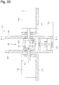
- FIG. 33 is a cross-sectional view of the main part of the moving transport mechanism.
- 34 is a cross-sectional view of a principal part taken along line AA in FIG.
- the omnidirectional wheel 110 has a wheel body 120 supported by a casing 112 so as to be rotatable about a rotation center axis 121.
- the roller 130 is supported by the wheel body 120 so as to be rotatable about a rotation axis 131 along a virtual circumference centered on the rotation center axis 121, and protrudes outward in the radial direction of the wheel body 120.
- the wheel main body 120 and the roller 130 rotate by distributing the rotation of the motors 114 a and 114 b via the differential mechanism 140.
- the differential mechanism 140 meshes with both the first and second input bevel gears 118a and 118b and the first and second input bevel gears 118a and 118b, which are rotatably arranged coaxially with the rotation center shaft 121.
- an output bevel gear 142 capable of rotating and revolving around the rotation center axis 121.
- the output bevel gear 142 is fixed to one end of the rotation shaft 143, and the rotation shaft 143 is rotatably supported by a rotation support member 126 fixed to the wheel body 120.
- the omnidirectional wheel 110 moves in an oblique direction intersecting the first and second linear directions (see, for example, Patent Document 1). .
- a typical manual or electric wheelchair can be moved in the front-rear direction (ie, moving forward or backward) or changing the direction of the wheelchair by sitting on the wheelchair and turning the left and right wheels with hands or motors.
- it cannot move in the horizontal direction, that is, in the horizontal direction.
- the wheelchair wheel is omnidirectional, lateral movement is possible.
- the omnidirectional wheel of Patent Document 1 can move in the lateral direction by rotating the roller with a motor, but the structure inside the wheel is complicated.
- the present invention is intended to provide a moving device that can move in the lateral direction in addition to the front-rear direction with a simple configuration.
- the present invention provides a mobile device configured as follows.
- the moving device includes (a) a first wheel unit, (b) a second wheel unit, and (c) the first wheel unit and the second wheel unit approaching each other in a first direction.
- a coupling unit that couples the first wheel unit and the second wheel unit so that the first wheel unit and the second wheel unit can be separated from each other; and (d) at least the first wheel unit in contact with a support surface.
- a first main wheel arranged so as to be able to move in a second direction perpendicular to the direction of 1; (e) the first main wheel and the first main wheel on the second wheel unit; A second main wheel disposed so as to face the direction and move in at least the second direction while being in contact with the support surface; and (f) the second wheel unit includes the second wheel unit.
- a first laterally movable state in which the first wheel unit is prohibited from moving to at least the other side in the first direction, and the second wheel unit is the first wheel unit.
- a second laterally movable state in which movement to at least the other side of the direction is prohibited and the first wheel unit is movable to at least the one side of the first direction
- a lateral movement mechanism capable of
- the movement of the moving device in the second direction and the turning by the combination of the movement of the first main wheel in the second direction and the movement of the second main wheel in the second direction can be made possible.
- the second wheel unit moves to one side in the first direction when in the first lateral movement enabled state
- the first wheel unit moves to one side in the first direction when in the second lateral movement enabled state
- the moving device can move to one side in the first direction.
- At least one of the first main wheel and the second main wheel is an outer periphery of the wheel body such that the wheel body protrudes radially outward of the wheel body and contacts the support surface.
- a roller disposed along the wheel body, movable in the first direction by rotation of one of the wheel body and the roller, and movable in the second direction by rotation of the other.
- the lateral movement mechanism includes: (i) a first brake mechanism capable of prohibiting rotation of the wheel main body and the roller of the first main wheel; and (ii) the second main main wheel. It includes at least one of a second brake mechanism that can inhibit rotation of the one of the wheel main body and the roller of the wheel.
- the first lateral movement when the first lateral movement is enabled by the first brake mechanism, the first main wheel is prohibited from moving in the first direction, and the first wheel unit is prohibited from moving in the first direction.
- the prohibition of the movement of the first main wheel in the first direction is released, and the movement of the first wheel unit in the first direction is enabled. Can do.
- the second brake mechanism when the first lateral movement is possible, the prohibition of the movement of the second main wheel in the first direction is released, and the movement of the second wheel unit in the first direction becomes possible.
- the second lateral movement enabled state the second main wheel is prohibited from moving in the first direction, and the second wheel unit is prohibited from moving in the first direction.
- At least one of the first main wheel and the second main wheel is an outer periphery of the wheel body such that the wheel body protrudes radially outward of the wheel body and contacts the support surface.
- a roller disposed along the wheel body, movable in the first direction by rotation of one of the wheel body and the roller, and movable in the second direction by rotation of the other. .
- the lateral movement mechanism (i) allows one of the forward and reverse rotations of the first main wheel and the roller of the first main wheel, and prohibits the other, and A first rotatable direction switching mechanism capable of switching a permitted / prohibited direction among the two forward and reverse rotations; and (ii) one of the wheel main body and the roller of the second main wheel.
- a second rotatable direction switching mechanism capable of allowing one of the two forward and reverse rotations and prohibiting the other and switching the permitted / prohibited direction of the two forward and reverse rotations. And at least one of them.
- the first main wheel is prohibited from moving to the other side in the first direction when the first rotatable direction switching mechanism is in the first lateral movement enabled state.
- the first main wheel is permitted to move to the first side in the first direction, and the first wheel unit It is possible to enable movement in one direction in one direction.
- the second main wheel is allowed to move to one side in the first direction when the second rotatable direction switching mechanism is in the first laterally movable state, and the first direction of the second wheel unit is The second main wheel is prohibited from moving to the other side in the first direction and the second wheel unit is moved in the first direction. The movement to the other side can be prohibited.
- the lateral movement mechanism includes a two-way wheel and a brake mechanism.
- the two-way wheel is (a) disposed on at least one of the first wheel unit and the second wheel unit, and (b) the wheel body and the support surface projecting radially outward of the wheel body. (C) movable in the first direction by rotation of one of the wheel body and the roller, and the other of the rollers. It can move in the second direction by rotation.
- the said brake mechanism can prohibit rotation of at least 1 direction among the rotation of the said wheel main body of the said two-way wheel which can be moved to the said 1st direction, or the normal / reverse 2 directions of the roller.
- the first main wheel protrudes outward in the radial direction of the wheel main body and the wheel main body so as to contact the support surface.
- the second main wheel protrudes outward in the radial direction of the wheel main body and the wheel main body so as to contact the support surface.
- a roller disposed along the outer periphery of the wheel movable in the first direction by rotation of one of the wheel body and the roller, and movable in the second direction by rotation of the other. It is.
- the brake mechanism prohibits the movement of the two-way wheel in the first direction when the first lateral movement is possible.
- the prohibition on the movement of the two-way wheel in the first direction is canceled and the movement of the first wheel unit in the first direction is possible.
- the prohibition of the movement of the two-way wheel in the first direction is canceled by the brake mechanism when the first wheel is in the first lateral movement state.
- the unit can move in the first direction and the second lateral movement is possible, the two-way wheel is prohibited from moving in the first direction, and the second wheel unit is not allowed to move in the first direction. Can be done.
- the lateral movement mechanism is (i) disposed in the first wheel unit, can move in the second direction while being in contact with the support surface, and is in contact with the support surface.
- a first restricting wheel in which movement of at least the other side in the first direction is prohibited, the first restricting wheel being in contact with the support surface;
- a first restricting mechanism that can be moved to one retreat position; and (ii) disposed in the second wheel unit, and can move in the second direction while contacting the support surface; and A second contact position where the second restriction wheel is in contact with the support surface, the second restriction wheel being prohibited from moving on at least the other side in the first direction while being in contact with the support surface.
- a second retracted position away from the support surface Can be moved to a preparative includes a second regulating mechanism, at least one of.
- the lateral movement mechanism includes the first restricting mechanism
- the first main wheel is disposed on an outer periphery of the wheel body such that the wheel main body protrudes radially outward of the wheel body and contacts the support surface.
- the second main wheel protrudes outward in the radial direction of the wheel body and the wheel body so as to contact the support surface.
- the first regulating wheel comes into contact with the support surface and the first wheel unit is prohibited from moving in the first direction by the first regulating mechanism.
- the first restricting wheel can be separated from the support surface, and the first wheel unit can be moved in the first direction.
- the second restriction mechanism when the first lateral movement is possible, the second restriction wheel is separated from the support surface, and the second wheel unit can move in the first direction, and the second lateral movement is possible. In the state, the second restriction wheel can be brought into contact with the support surface, and movement of the second wheel unit in the first direction can be prohibited.
- the lateral movement mechanism includes (i) a first restriction wheel that is disposed on the first wheel unit and is movable only in one direction while being in contact with the support surface.
- the direction of the wheel can be moved in the first direction while being in contact with the support surface, and the second direction can be moved in the second direction while being in contact with the support surface.
- a first restricting mechanism that can be switched to an orientation; and (ii) a second restricting wheel that is disposed on the second wheel unit and that can move only in one direction while contacting the support surface, The direction of the second restriction wheel can be moved in the first direction while being in contact with the support surface, and can be moved in the second direction while being in contact with the support surface.
- the 2nd regulation machine which can be switched to the 4th direction which is When, at least one of.
- the lateral movement mechanism includes the first restricting mechanism
- the first main wheel is disposed on an outer periphery of the wheel body such that the wheel main body protrudes radially outward of the wheel body and contacts the support surface.
- the second main wheel protrudes outward in the radial direction of the wheel body and the wheel body so as to contact the support surface.
- the first restricting mechanism causes the first restricting wheel to be in the second direction when the first lateral movement is possible, and the movement of the first wheel unit in the first direction is prohibited.
- the direction of the first restriction wheel is the first direction, and the first wheel unit can be moved in the first direction.
- the direction of the second restriction wheel becomes the third direction, and the second wheel unit can move in the first direction.
- the direction of the second restriction wheel is the fourth direction, and the movement of the second wheel unit in the first direction can be prohibited.
- the lateral movement mechanism includes (i) a first release wheel that is disposed on the first wheel unit and can move to at least one side in the first direction while being in contact with the support surface. , By moving at least one of the first release wheel and the first main wheel, the first main wheel is separated from the support surface, and the first release wheel is in contact with the support surface A first wheel switching mechanism that can be in a first released state and a first restricted state in which the first main wheel is in contact with the support surface; and (ii) the second wheel unit.
- a second release wheel that is disposed and is capable of moving to at least one side in the first direction while contacting the support surface, wherein at least one of the second release wheel and the second main wheel The second main wheel is moved to the support surface
- the second release state in which the second release wheel is in contact with the support surface and the second restricted state in which the second main wheel is in contact with the support surface can be achieved.
- at least one of the two wheel switching mechanisms When the lateral movement mechanism includes the first wheel switching mechanism, the first main wheel is movable only in the second direction while being in contact with the support surface.
- the second wheel switching mechanism the second main wheel is movable only in the second direction while being in contact with the support surface.
- the first wheel switching mechanism when the first wheel switching mechanism is in the first lateral movement enabled state, the first main wheel is in contact with the support surface, and the movement of the first wheel unit in the first direction is prohibited, and the second The first main wheel is separated from the support surface and the first release wheel is in contact with the support surface so that the first wheel unit can move in the first direction when Can do.
- the second wheel switching mechanism By the second wheel switching mechanism, the second main wheel is separated from the support surface, the second release wheel is in contact with the support surface, and the first wheel unit of the second wheel unit is in the first laterally movable state. It is possible to move in the direction, and when the second lateral movement is possible, the second main wheel comes into contact with the support surface and the movement of the second wheel unit in the first direction can be prohibited. .
- At least one of the first main wheel and the second main wheel is (a) movable to one side of the first direction while being in contact with the support surface, and the first direction.
- One side wheel prohibited from moving to the other side, and (b) moving to the other side in the first direction while contacting the support surface, and moving to the one side in the first direction And the other wheel on which is prohibited.
- the lateral movement mechanism (i) a first state in which one of the one side wheel and the other side wheel, which are the first main wheels, is in contact with the support surface and the other is separated from the support surface.
- a first main wheel switching mechanism capable of switching between a second state in which the other is in contact with the support surface and the one is away from the support surface; and (ii) the second main wheel A third state in which one of the one side wheel and the other side wheel is in contact with the support surface and the other is away from the support surface, the other is in contact with the support surface, and the one is in the support It includes at least one of a second main wheel switching mechanism capable of switching between a fourth state separated from the surface.
- the first main wheel switching mechanism when the first main wheel switching mechanism is in the first lateral movement enabled state, the first main wheel in contact with the support surface is prohibited from moving to the other side in the first direction.
- the wheel unit When the wheel unit is not allowed to move to the other side in the first direction and is in the second laterally movable state, the first main wheel in contact with the support surface moves to one side in the first direction. The movement is permitted, and the first wheel unit can be moved to one side in the first direction.
- the second main wheel switching mechanism permits the second main wheel in contact with the support surface to move to one side in the first direction when the first lateral movement is possible, and the second wheel unit.
- the second main wheel in contact with the support surface is prohibited from moving to the other side in the first direction when the second lateral movement is possible.
- the movement of the second wheel unit to the other side in the first direction can be prohibited.
- the lateral movement mechanism is (i) a first moving the first main wheel to a first contact position in contact with the support surface and a first retracted position away from the support surface.
- a main wheel moving mechanism ; and (ii) a second main wheel movement for moving the second main wheel to a second contact position in contact with the support surface and a second retreat position away from the support surface.
- the first main wheel can move only in the second direction while being in contact with the support surface.
- the lateral movement mechanism includes the second main wheel movement mechanism
- the second main wheel can move only in the second direction while being in contact with the support surface.
- the first main wheel moving mechanism when the first main wheel moving mechanism is in the first laterally movable state, the first main wheel is in contact with the support surface, and the movement of the first wheel unit in the first direction is prohibited.
- the first main wheel In the state in which two lateral movements are possible, the first main wheel can be separated from the support surface, and the first wheel unit can be moved in the first direction.
- the second main wheel moving mechanism When the second main wheel moving mechanism is in the first lateral movement enabled state, the second main wheel is separated from the support surface, and the second wheel unit can move in the first direction.
- the second main wheel In the movable state, the second main wheel is in contact with the support surface, and the movement of the second wheel unit in the first direction can be prohibited.
- the lateral movement mechanism includes the first main wheel movement mechanism and the second main wheel movement mechanism.
- the coupling unit includes: (i) an intermediate body on which an intermediate wheel that can move to at least one side in the first direction while being in contact with the support surface; and (ii) the first wheel unit; A first coupling mechanism that couples the intermediate body so that the intermediate body can move toward and away from each other in the first direction; and (iii) the second wheel unit and the intermediate body, A second coupling mechanism that couples the first direction and the second coupling mechanism so as to be close to and away from each other.
- the lateral movement mechanism is (i) moving the center of gravity of the first wheel unit in a direction away from the support surface in a state where the first main wheel is in contact with the support surface.
- a first center-of-gravity moving mechanism capable of moving the first main wheel away from the support surface; and (ii) the second wheel unit in a state where the second main wheel is in contact with the support surface.
- At least one of a second center-of-gravity movement mechanism capable of moving the second main wheel away from the support surface by moving the center of gravity of the vehicle in a direction away from the support surface.
- the first main wheel when the first lateral movement state is enabled, the first main wheel is in contact with the support surface and the movement of the first wheel unit in the first direction is prohibited by the first center-of-gravity movement mechanism.
- the first main wheel can be separated from the support surface and can move in the first direction of the first wheel unit.
- the second center of gravity moving mechanism when the first lateral movement is possible, the second main wheel is separated from the support surface, and the second wheel unit can be moved in the first direction.
- the second main wheel When in a possible state, the second main wheel is in contact with the support surface, and movement of the second wheel unit in the first direction can be prohibited.
- the coupling unit is coupled so that (i) the intermediate body and (ii) the first wheel unit and the intermediate body can be moved toward and away from each other in the first direction.
- a first coupling mechanism, and (iii) a second coupling mechanism that couples the second wheel unit and the intermediate body so as to be close to and away from each other in the first direction. including.
- the user can board the intermediate body.
- the first coupling mechanism is a first linear motion guide mechanism that couples the first wheel unit and the intermediate body so as to be relatively movable in the first direction.
- the second coupling mechanism is a second linear motion guide mechanism that couples the second wheel unit and the intermediate body so as to be relatively movable in the first direction.
- the configuration can be simplified.
- the coupling unit includes (i) an intermediate body, (ii) a first linear motion guide mechanism that couples the first wheel unit and the intermediate body so as to be relatively movable in the first direction. And (iii) a second linear motion guide mechanism that couples the second wheel unit and the intermediate body so as to be relatively movable in the first direction.
- the lateral movement mechanism includes the first brake mechanism or the first restriction mechanism, and the second brake mechanism or the second restriction mechanism.
- a first operation unit for operating the first brake mechanism or the first restriction mechanism is disposed on the first wheel unit.
- a second operation unit for operating the second brake mechanism or the second restriction mechanism is disposed on the second wheel unit.
- a user sitting on the intermediate body uses the first operation unit and the second operation unit to use the first brake mechanism or the first restriction mechanism, the second brake mechanism, or the second operation unit.
- the moving device can be moved in the first direction by operating the restriction mechanism or by relatively moving the first and second wheel units.
- the moving device of the present invention can move not only in the front-rear direction but also in the lateral direction with a simple configuration.
- FIG. 1 is an explanatory diagram showing the configuration of the mobile device.
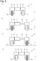
- Example 1-1 FIG. 2 is an explanatory diagram of the operation of the mobile device.
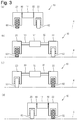
- Example 1-1 FIG. 3 is an explanatory diagram of the operation of the mobile device.
- Example 1-1 FIG. 4 is an explanatory diagram of the operation of the mobile device.
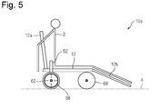
- Example 1-1 FIG. 5 is a side view of the moving device.
- FIG. 6 is a plan view of the main part of the moving device.
- FIG. 7 is a cross-sectional view of a main part of the moving device.
- FIG. 8 is a cross-sectional view of a main part of the moving device.
- FIG. 9 is a side view of the main part of the moving device.
- FIG. 10 is a cross-sectional view of a main part of the moving device.
- FIG. 11 is a cross-sectional view of a main part of the moving device.
- FIG. 12 is an explanatory diagram of the operation of the mobile device.
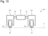
- FIG. 13 is an explanatory diagram showing the configuration of the mobile device.
- Example 1-2 FIG. 15 is an explanatory diagram showing the configuration of the moving device.
- Example 2-1 FIG. 16 is an explanatory diagram showing the configuration of the moving device.
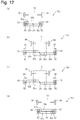
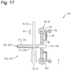
- FIG. 17 is a cross-sectional view of a main part of the moving device. (Specific example 2) FIG.
- FIG. 18 is an explanatory diagram showing the configuration of the moving device.
- FIG. 19 is an explanatory diagram showing the configuration of the mobile device.
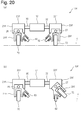
- FIG. 20 is an explanatory diagram showing the configuration of the mobile device.
- FIG. 21 is an explanatory diagram showing the configuration of the moving device.
- FIG. 22 is an explanatory diagram showing the configuration of the moving device.
- FIG. 23 is an explanatory diagram showing the configuration of the mobile device.
- FIG. 24 is an explanatory diagram showing the configuration of the moving device.
- FIG. 25 is an explanatory diagram showing the configuration of the moving device.
- Example 3-1 FIG.
- FIG. 26 is an explanatory diagram of the operation of the mobile device.
- Example 3-1 FIG. 27 is an explanatory diagram of the operation of the mobile device.
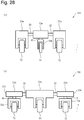
- Example 3-1 FIG. 28 is an explanatory diagram showing the configuration of the moving device.
- Example 3-2 FIG. 29 is an explanatory diagram showing the configuration of the moving device.
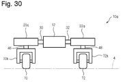
- Example 4 FIG. 30 is an explanatory diagram showing the configuration of the mobile device.
- FIG. 31 is an explanatory diagram of the operation of the mobile device.
- FIG. 32 is an explanatory diagram of the operation of the moving device.
- FIG. 33 is a cross-sectional view of a main part of the moving conveyance mechanism.
- FIG. 34 is a cross-sectional view of a principal part taken along line AA in FIG. 33.
- the coupling unit includes an intermediate body and first and second linear motion guide mechanisms, the first and second main wheels are omni wheels, and the first and second brakes serve as lateral movement mechanisms.
- a mechanism or first and second rotatable direction switching mechanisms are provided.
- FIG. 1 is an explanatory diagram conceptually showing the configuration of the moving apparatus 10.
- 2 to 4 are explanatory diagrams of the operation of the moving device 10.
- the right direction on the paper is the right direction of the moving device
- the left direction on the paper is the left direction of the moving device
- the moving device 10 includes two wheel units 20 and 22, first and second linear motion guide mechanisms 30 and 32, and an intermediate body 12.
- the first wheel unit 20 is coupled to the left side of the intermediate body 12 via the first linear motion guide mechanism 30, and the second wheel is connected to the right side of the intermediate body 12 via the second linear motion guide mechanism 32.
- the wheel unit 22 is coupled.
- the linear motion guide mechanisms 30 and 32 couple the wheel units 20 and 22 and the intermediate body 12 so as to be relatively movable in the left-right direction (that is, the first direction) of the moving device 10.
- the linear motion guide mechanisms 30 and 32 have, for example, a first member and a second member arranged so as to be linearly movable along the first member as in Specific Example 1 described later.
- the two members are fixed, and the first member is fixed to the wheel units 20 and 22.
- the linear motion guide mechanisms 30 and 32 are arranged so that the direction in which the second member moves relative to the first member is the left-right direction of the moving device 10.
- the first member may be fixed to the intermediate body 12 and the second member may be fixed to the wheel units 20 and 22.
- the movement of the second member relative to the first member of the linear motion guide mechanisms 30 and 32 will be referred to as expansion and contraction of the linear motion guide mechanisms 30 and 32.
- the distance in the left-right direction between the wheel units 20 and 22 and the intermediate body 12 changes due to the expansion and contraction of the linear motion guide mechanisms 30 and 32.
- the wheel units 20 and 22 include main bodies 21 and 23 fixed to the first member or the second member of the linear motion guide mechanisms 30 and 32, and wheel support portions 60k and 62k that rotatably support the omni wheels 60 and 62, respectively.
- the first and second wheel units 20 and 22 include omni wheels 60 and 62 as the first and second main wheels.
- the omni wheels 60 and 62 one or a plurality of rollers are rotatably supported along the outer periphery of the disc-shaped wheel body, and the rollers protrude outward in the radial direction of the wheel body.
- the omni wheels 60 and 62 move in one direction when the wheel body rotates and the roller moves integrally with the wheel body (hereinafter, also simply referred to as “the wheel body rotates”).
- the roller rotates When rotating relative to the wheel body (hereinafter also simply referred to as “the roller rotates”), it moves in the other direction.
- the direction of the rotation center axis of the roller substantially coincides with the circumferential direction around the rotation center axis of the wheel body, and the direction of movement when the wheel body rotates and the direction of movement when the roller rotates
- it is orthogonal it is also possible to configure it to intersect diagonally.
- the two omni wheels 60 and 62 have the same configuration, and have the same outer diameter (twice the distance between the contact point of the roller in contact with the support surface 4 and the center axis of rotation of the wheel body).
- the rotation center axes of the respective wheel bodies are arranged so as to be parallel and coaxial with the left-right direction of the moving device 10. Therefore, when the rollers of the omni wheels 60, 62 rotate in the same direction at the same speed, the moving device 10 moves in the left-right direction (first direction) of the moving device 10, and the wheel bodies of the omni wheels 60, 62 are the same. When rotating in the direction at the same speed, the moving device 10 moves in the front-rear direction of the moving device 10 (that is, the second direction perpendicular to the first direction).
- the omni wheels 60 and 62 are disposed on the wheel units 20 and 22 so as to face each other in the first direction.
- Each of the wheel units 20 and 22 includes a state in which relative rotation of the omni wheels 60 and 62 with respect to the wheel body (hereinafter referred to as “roller rotation”) is prohibited, and a state in which the prohibition of rotation of the roller is released. (Not shown) is provided.
- the wheel units 20 and 22 are prohibited from rotating in the left-right direction when the brake is on, and thus are prohibited from moving in the left-right direction. It can be moved.
- the brake mechanism is, for example, a disc-shaped brake pad that rotates coaxially with the rotational center axis of the wheel body of the omni wheel at the same angular speed as the angular speed of the wheel body of the omni wheel and moves in the direction of the rotational center axis of the wheel body.
- the rotation of the roller is prevented by bringing the brake pad into contact with the roller, and the rotation of the roller is enabled by moving the brake pad away from the roller.
- ⁇ Brake pads may be arranged on both sides of the omni wheel so that the roller is sandwiched between them, or may be contacted from both sides of the roller, may be arranged only on one side of the omni wheel, and may be contacted only from one side of the roller.
- the two brake pads installed on both sides of the omni wheel are moved in the direction approaching the omni wheel, and brought into contact with the roller.
- the omni wheel and one brake pad are arranged so as to be movable in the direction of the rotation center axis of the wheel body of the omni wheel, and the other brake pad is arranged so as to be immovable in the direction of the rotation center axis.
- One brake pad is moved in the direction of the rotation center axis, the omni wheel is urged by one brake pad to move the omni wheel in the rotation axis direction, and the roller of the omni wheel is brought into contact with the other brake pad. Good.
- Rotation of the wheel body of the omni wheels 60 and 62, expansion and contraction of the linear motion guide mechanisms 30 and 32, and ON / OFF switching of the roller brakes of the omni wheels 60 and 62 can be actively performed.
- the term “actively performed” as used herein includes not only a case where it is performed by a driving source such as a motor but also a case where a person such as a user of the moving apparatus performs. That is, it is driven with the intention to operate. When a person does not use a drive source such as a motor, those parts are passive by themselves. In the following embodiments, the meaning of “active” is the same.
- the moving device 10 is configured by appropriately combining the rotation of the wheel bodies of the omni wheels 60 and 62, the expansion and contraction of the linear motion guide mechanisms 30 and 32, and the ON / OFF of the brake, It is possible to turn.
- the moving device 10 is moved in the front-rear direction by rotating the wheel body of the omni wheels 60 and 62 in the same direction at the same rotational speed in a state where the roller brakes of the omni wheels 60 and 62 are turned on and rotation of the rollers is prohibited. Can be realized.
- the turning of the moving device 10 can be performed by rotating the wheel bodies of the omni wheels 60 and 62 in the same direction at different rotational speeds in a state in which the rollers of the omni wheels 60 and 62 are turned on and the rotation of the rollers is prohibited. This can be realized by rotating the wheel bodies of the omni wheels 60 and 62 in different directions or by rotating only one wheel body of the omni wheels 60 and 62.
- the movement of the moving device 10 in the left and right direction is realized by performing expansion / contraction of the linear motion guide mechanisms 30 and 32 and switching ON / OFF of the brakes of the rollers of the omni wheels 60 and 62 in an appropriate order. it can.
- three lateral movement methods will be described with reference to FIGS. 2 to 4 for moving the moving device 10 in the right direction. 2 to 4, the omni wheels 60 and 62 indicated by hatching indicate that the roller brake is ON, and the omni wheels 60 and 62 not indicated by hatching indicate that the roller brake is OFF.
- the first lateral movement method will be described with reference to FIG.
- the second linear motion guide mechanism 32 of the two linear motion guide mechanisms 30 and 32 is expanded and contracted.
- the roller brake of the first omni wheel 60 is ON and the roller brake of the second omni wheel 62 is in a state where the second linear motion guide mechanism 32 is contracted.
- the OFF state is the initial state.
- the second linear motion guide mechanism 32 is extended.
- the first wheel unit 20 does not move in the left-right direction (lateral direction) because the roller brake of the omni wheel 60 is ON. Since the brake of the roller of the omni wheel 62 is OFF, the second wheel unit 22 moves to the right by the same distance as the extended length of the second linear motion guide mechanism 32. Similar to the first wheel unit 20, the intermediate body 12 does not move in the lateral direction.
- the second wheel unit 22 can move in at least one side (right side) in the first direction (left-right direction), and the first wheel unit 20 can move in at least the other side in the first direction.
- the second wheel unit 22 can be moved to one side (right side) in the first direction while the first wheel unit 20 is stationary.
- the roller brake of the first omni wheel 60 is turned off and the roller brake of the second omni wheel 62 is turned on.
- the second linear motion guide mechanism 32 is contracted as shown in FIG.
- the brake of the roller of the omni wheel 62 is ON, the second wheel unit 22 does not move in the lateral direction. Since the brake of the roller of the omni wheel 60 is OFF, the first wheel unit 20 moves to the right by the same distance as the contracted length of the second linear motion guide mechanism 32. Similarly to the first wheel unit 20, the intermediate body 12 moves to the right by the same distance as the first wheel unit 20.
- the second wheel unit 22 is prohibited from moving to at least the other side (left side) in the first direction, and the first wheel unit 20 is moved to at least one side (right side) in the first direction.
- This is a second laterally movable state where movement is possible.
- the first wheel unit 20 can be moved to one side (right side) in the first direction while the second wheel unit 22 is stationary.
- the moving device 10 can move an arbitrary distance in the right direction.
- this rightward movement is an intermittent movement that repeats stopping and moving.
- the moving device 10 moves in the right direction by the same operation by expanding and contracting only the first linear motion guide mechanism 30. be able to.
- the second lateral movement method will be described with reference to FIG.
- the first and second linear motion guide mechanisms 30 and 32 are simultaneously expanded and contracted.
- the first and second linear motion guide mechanisms 30 and 32 are contracted, the brake of the roller of the first omni wheel 60 is ON, and the second omni wheel 62.
- the state in which the brake of the roller is OFF is the initial state.
- the first and second linear motion guide mechanisms 30 and 32 are extended.
- the brake of the roller of the omni wheel 60 is ON, the first wheel unit 20 does not move in the lateral direction.
- the second wheel unit 22 since the roller brake of the omni wheel 62 is OFF, the length obtained by extending the second linear motion guide mechanism 32 and the length obtained by extending the first linear motion guide mechanism 30 are added. Move to the right by the distance. The intermediate body 12 moves rightward by the same distance as the length of the first linear guide mechanism 30.
- the second wheel unit 22 is moved to the first while the first wheel unit 20 remains stationary. Move to one side (right side) of direction.
- the roller brake of the first omni wheel 60 is turned off and the roller brake of the second omni wheel 62 is turned on.
- the first and second linear motion guide mechanisms 30 and 32 are contracted.
- the second wheel unit 22 does not move laterally because the roller brake of the omni wheel 62 is ON.
- the length of the second linear motion guide mechanism 32 and the length of the first linear motion guide mechanism 30 are added. Move to the right by the distance.
- the intermediate body 12 moves rightward by the same distance as the contracted length of the second linear motion guide mechanism 32.
- the first and second linear motion guide mechanisms 30 and 32 are contracted to move the first wheel unit 20 to the first while the second wheel unit 22 remains stationary. Move to one side (right side) of direction.
- the moving device 10 can move an arbitrary distance in the right direction.
- this rightward movement is an intermittent movement that repeats stopping and moving.
- the third lateral movement method will be described with reference to FIG.
- the first and second linear motion guide mechanisms 30 and 32 are separately expanded and contracted.
- the first linear motion guide mechanism 30 in the initial state, the first linear motion guide mechanism 30 is in a contracted state, and the second linear motion guide mechanism 32 is in a state of being extended to a length that can be sufficiently expanded and contracted. And, the brake of the roller of the first omni wheel 60 is OFF, and the brake of the roller of the second omni wheel 62 is ON.
- the first linear motion guide mechanism 30 is extended while the second linear motion guide mechanism 32 is contracted, and the brake of the roller of the first omni wheel 60 is turned ON.
- the second linear motion guide mechanism 32 is quickly extended while continuing to extend the first linear motion guide mechanism 30. That is, by extending the first and second linear motion guide mechanisms 30 and 32 in the first laterally movable state, the second wheel unit 22 is moved to the first while the first wheel unit 20 remains stationary. Move to one side (right side) of direction.
- the brake of the roller of the first omni wheel 60 is braked while continuing to extend the first linear motion guide mechanism 30 and contract the second linear motion guide mechanism 32. Turn off.
- the first linear motion guide mechanism 30 is quickly contracted while continuing to contract the second linear motion guide mechanism 32. That is, in the second movable state, the first and second linear motion guide mechanisms 30 and 32 are contracted to move the first wheel unit 20 to the first while the second wheel unit 22 remains stationary. Move to one side (right side) of direction.
- the moving device 10 can move an arbitrary distance in the right direction.
- the intermediate body 12 is driven in the right direction by expansion and contraction of at least one linear motion guide mechanism 30, 32 at any stage.
- this rightward movement is a continuous movement that always moves rightward.
- left and right movements are possible by switching the left and right in the first to third lateral movement methods.
- the first and second linear motion guide mechanisms 30 and 32 can be sufficiently expanded and contracted in the range necessary for lateral movement in the initial state.
- an initial state different from the above may be used.
- the movement due to the inertia of the moving device 10 or the intermediate body 12 may be used during the movement. Since the linear motion guide mechanisms 30 and 32 are extendable, for example, when the brakes of the rollers of the two omni wheels 60 and 62 are temporarily turned off while the moving device 10 is moving rightward, Even if it is not driven, that is, even if the active guides 30 and 32 are stopped, the moving device 10 continues to move rightward for a while. In addition, when the intermediate body 12 is moving in the right direction, the expansion and contraction of the two linear motion guide mechanisms 30 and 32 is temporarily enabled to be passive, that is, the linear motion guide mechanisms 30 and 32 are activated actively. If the expansion and contraction is temporarily stopped and can be freely expanded and contracted, the intermediate body 12 continues to move to the right due to inertial force for a while without driving to the right.
- the moving device 10 of the present embodiment can move and turn in the front-rear direction by the rotation of the wheel bodies of the first and second omni wheels 60 and 62. It can move in the left-right direction (lateral direction) by the expansion / contraction of the linear motion guide mechanisms 30, 32 and the ON / OFF switching of the brakes of the rollers of the omni wheels 60, 62.
- By carrying out the first to third lateral movement methods by simultaneously performing the movement in the front-rear direction and the movement in the left-right direction, that is, rotating the wheel bodies of the omni wheels 60, 62 in the same direction at the same speed. , Can move in an oblique direction.
- the rotation of the wheel bodies of the omni wheels 60 and 62, the expansion and contraction of the linear motion guide mechanisms 30 and 32, and the ON / OFF switching of the brake may be realized by driving with human power or by a drive source such as a motor. It may be realized by driving.
- a drive source such as a motor.
- other wheels may be provided, and auxiliary wheels that are not actively driven may be provided.
- the rotation center axes of the wheel bodies of the two omni wheels 60 and 62 may be arranged so as to be parallel to each other and have different heights.
- FIG. 5 is a side view of the moving device 10s.
- FIG. 6 is a plan view of a main part of the moving device 10s.
- the intermediate body 12 is indicated by a chain line, and the backrest plate 12a and the footrest plate 12b are not shown.
- the backrest plate 12 a and the footrest plate 12 b are coupled to the intermediate body 12 on which the user 2 sits.
- the first wheel unit 20 including the first omni wheel 60 is coupled to the rear left side of the intermediate body 12 via the first linear motion guide mechanism 30.
- a second wheel unit 22 including a second omni wheel 62 is coupled to the rear right side of the intermediate body 12 via a second linear motion guide mechanism 32.
- a third omni wheel 66 is rotatably supported on the left side of the front portion of the intermediate body 12.
- a fourth omni wheel 68 is rotatably supported on the front right side of the intermediate body 12.
- the omni wheels 60, 62, 66, 68 are in contact with the support surface 4 such as the ground surface or the floor surface.
- the linear motion guide mechanisms 30 and 32 include rod-shaped first members 30 b and 32 b and second members 30 a and 32 a that are linearly movable along the first members 30 b and 32 b. Have.
- the second members 30 a and 32 a are fixed to the intermediate body 12.
- the first members 30b and 32b protrude from the intermediate body 12 when moved relative to the second members 30a and 32a.
- the linear motion guide mechanisms 30 and 32 are arranged such that the direction in which the first members 30b and 32b move relative to the second members 30a and 32a is parallel to the left-right direction of the moving device 10s.
- the linear motion guide mechanisms 30 and 32 are prohibited from relative movement of the first members 30b and 32b with respect to the second members 30a and 32a by the lock mechanism 29 provided at an appropriate position of the intermediate body 12. In addition, you may arrange
- the lock mechanism 29 can be omitted.
- the wheel units 20, 22 are provided on the main bodies 21, 23 with the main bodies 21, 23 fixed to the ends of the first members 30 b, 32 b of the linear motion guide mechanisms 30, 32 on the side protruding from the intermediate body 12.
- the wheel bodies of the omni wheels 60 and 62 are rotatably supported by the shaft portions 21z and 23z.
- the main bodies 21 and 23 are provided with first and second levers 50 and 52 which are first and second operation parts for operating the brakes of the rollers of the omni wheels 60 and 62.
- FIG. 7 and 8 are cross-sectional views of the main part of the moving device 10s, showing a cross section perpendicular to the support surface 4 and passing through the rotation center axis of the wheel body 34 of the omni wheels 60 and 62.
- FIG. FIG. 9 is a side view of the main part viewed along line AA in FIG.
- FIG. 10 is a cross-sectional view of the principal part taken along line BB in FIG.
- FIG. 11 is a cross-sectional view of the principal part taken along line CC in FIG.
- each of the first and second omni wheels 60 and 62 includes a wheel body 34 and a plurality of rollers 36 disposed along the outer periphery of the wheel body 34.
- the roller 36 is supported by the wheel body 34 so as to be rotatable about a rotation axis along a virtual circumference centered on the rotation center axis of the wheel body 34, and protrudes radially outward from the wheel body 34.
- the wheel body 34 of the first and second omni wheels 60, 62 is rotated via a bearing 35 on shafts 21 z, 23 z provided on the bodies 21, 23 of the first and second wheel units 20, 22. It is supported freely.
- An annular member 38 is fixed to the wheel body 34 so as to be exposed on the side opposite to the intermediate body 12, and the annular member 38 and the wheel body 34 rotate together.
- first and second omni wheels 60 and 62 are adjacent to the first and second omni wheels 60 and 62, respectively, and the rotation of the roller 36 of the first and second omni wheels 60 and 62 is prohibited or permitted.
- First and second operation mechanisms 26 and 28 are provided.
- the first and second operation mechanisms 26 and 28 include a support portion 44, a contact member 40 that is a first and second brake, a spring 40x, and first and second operation portions that are first and second operation portions.
- Second levers 50 and 52 and an L arm 54 are included.
- the support portion 44 has a hollow cylindrical shape, and is fixed to the wheel main body 34 so as to be coaxial with the wheel main body 34 and protrude toward the intermediate body 12 side.
- the contact member 40 has a pair of side plates 40 s and 40 t having round holes 40 p and 40 q formed in the center and having a circular outer shape, which are coaxially coupled to each other with a predetermined interval in the direction of the rotation center axis of the wheel body 34.
- a support portion 44 is inserted into the round hole 40q of one side plate 40t of the contact member 40 with a gap therebetween, and the radial movement range of the contact member 40 is restricted.
- the spring 40x connects the contact member 40 and the wheel body 34, and the tension member pulls the contact member 40 toward the wheel body 34 so that the contact member 40 is pressed against the outer peripheral surface of the roller 36. .
- the contact member 40 rotates integrally with the wheel body 34. When the contact member 40 contacts the outer peripheral surface of the roller 36, the rotation of the roller 36 is prohibited.
- the contact member 40 is not limited to the configuration in contact with the outer peripheral surface of the roller 36, but may be configured to prohibit rotation of the roller 36 by contacting a portion other than the outer peripheral surface of the roller 36, for example, an axially perpendicular end surface. Good.
- the first and second levers 50 and 52 are movably inserted into through holes 21x and 23x formed in the main bodies 21 and 23 of the first and second wheel units 20 and 22, respectively.
- flanges 50s, 50t; 52s, 52t for restricting the moving ranges of the first and second levers 50, 52 are formed.
- the moving direction of the first and second levers 50 and 52 is not limited to the vertical direction indicated by the arrow 80, but may be any direction different from the horizontal direction of the moving device 10s.
- a first piece 54a and a second piece 54b are joined in an L shape.
- the L arm 54 is connected to a link support portion 55 in which a connecting portion 54c between the first piece 54a and the second piece 54b is fixed to the lower portions of the main bodies 21 and 23 of the first and second wheel units 20 and 22.
- the first piece 54 a of the L arm 54 is linked to the lower portions of the first and second levers 50 and 52.
- a bearing 56 is fixed to the second piece 54 b of the L arm 54. The bearing 56 is disposed in the space 42 between the pair of side plates 40 s and 40 t of the contact member 40.
- the contact member 40 is disposed at the first and second rotation prohibition positions. That is, the abutting member 40 is pressed against the roller 36 by the tension of the spring 40 x and is in contact with the outer peripheral surface of all the rollers 36 to prohibit the rotation of the rollers 36. Since the rotation of the roller 36s in contact with the support surface 4 is also prohibited, the first and second omni wheels 60 and 62 cannot move in the left-right direction.
- the contact member 40 when the first and second levers 50 and 52 are raised, the contact member 40 is disposed at the first and second rotation permission positions. That is, the L arm 54 tilts in conjunction with the first and second levers 50 and 52, and the bearing 56 fixed to the second piece 54 b of the L arm 54 comes into contact with the other side plate 40 s of the contact member 40. Thus, the contact member 40 is tilted, and the contact member 40 is separated from the roller 36 s in contact with the support surface 4. As a result, the rotation prohibition of the roller 36s in contact with the support surface 4 is released and the rotation is possible, so that the first and second omni wheels 60 and 62 can move in the left-right direction.
- the contact member 40 rotates substantially integrally with the wheel body 34. That is, the contact member 40 rotates while changing the tilt direction with respect to the wheel body 34 so that the contact member 40 is kept away from the roller 36 s in contact with the support surface 4. Therefore, when the annular member 38 is rotated, the first and second omni wheels 60 and 62 move in the front-rear direction while being movable in the left-right direction (lateral direction) of the moving device 10s.
- first and second levers 50 and 52 are pushed out or pulled in the left-right direction while the first and second levers 50 and 52 are raised, the first and second levers 50 and 52 are pushed.
- the first and second main bodies 21 and 23 of the first and second wheel units 20 and 22 and the first and second main bodies 21 and 23 of the first and second wheel units 20 and 22 are supported.
- the omni wheels 60 and 62 move in the left-right direction together with the first and second levers 50 and 52.
- the operation of the moving device 10s will be described.
- the user 2 sitting on the intermediate body 12 operates the first lever 50 with the left hand and operates the second lever 52 with the right hand, thereby moving the moving device 10s to the left and right of the moving device 10s. It can be moved in the direction, that is, in the lateral direction.
- the user 2 sitting on the intermediate body 12 turns the annular member 38 fixed to the first and second omni wheels 60 and 62 by hand, so that the mobile device 10s can be moved in the same manner as a general wheelchair.
- the moving device 10s can be moved in the front-rear direction or the direction of the moving device 10s can be changed.
- FIG. 12 is an explanatory diagram of the operation of the moving device 10s, and shows a state where the moving device 10s is viewed from above.
- the intermediate body 12 is indicated by a chain line, and the backrest plate 12a and the footrest plate 12b are not shown.
- the first omni wheel 60 in which the rotation of the roller is prohibited by the lowering of the first lever 50 is stationary.
- the first first member 30b is extended from the intermediate body 12 by pushing the first lever 50 leftward, and the intermediate body 12 moves rightward away from the first omni wheel 60 accordingly. To do.
- the second omni wheel 62 permitted to move in the left-right direction when the second lever 52 is raised moves to the right as the intermediate body 12 moves to the right away from the first omni wheel 60.
- the second first member 32b is fed out from the intermediate body 12 by pushing the second lever 52 rightward, and the second omni wheel 62 moves rightward away from the intermediate body 12 accordingly. To do.
- stage (2) it is easy to understand the operation when the first and second levers 50 and 52 are operated simultaneously, but the order of operating the first and second levers 50 and 52 is arbitrary.
- the first and second levers 50 and 52 may be pushed out after one of the first and second levers 50 and 52 has been pushed out, or the first and second levers 50 and 52 may be alternately pushed out several times. .
- the first omni wheel 60 which is movable in the left-right direction when the first lever 50 is raised, moves in the direction approaching the intermediate body 12, and the first The first member 30 b is accommodated in the intermediate body 12.
- the second omni wheel which is prohibited from moving in the left-right direction due to the lowering of the second lever 52, is stationary, by pulling the second lever 52 in the left direction, the intermediate body 12 is The second omni wheel 62 moves in a direction approaching the stationary omni wheel 62, and the second first member 32 b is accommodated in the intermediate body 12.
- step (3) the order of operating the first and second levers 50 and 52 is arbitrary as in the step (2).
- first and second omni wheels 60 and 62 are extended from the intermediate body 12 when the intermediate body 12 has moved to the desired position, for example, the first and second levers 50 and 52 By bringing one side down and pulling the other side up to the intermediate body 12 side, and then lowering the other side and pulling one side up to the intermediate body 12 side, the first and first Two first members 30 b and 32 b are accommodated in the intermediate body 12.
- the moving device 10s can be moved in the left-right direction by the operation of the user 2 sitting on the moving device 10s.
- the step (5) is completed, the moving device 10s cannot be moved in the left-right direction.
- the wheel body 34 of the first and second omni wheels 60 and 62 is rotatable during the steps (1) to (5) for moving the moving device 10s in the left-right direction, the above-mentioned (1)
- the moving device 10s can be moved in the front-rear direction or the direction of the moving device 10s can be changed. Is possible.
- the moving device 10s can move the intermediate body 12 in the left-right direction without rotationally driving the rollers 36 of the first and second omni wheels 60, 62 using a driving source such as a motor. Therefore, it is possible to move in the left-right direction (lateral direction) with a simple configuration as compared with the case where the rollers of the omni wheel are rotationally driven using a drive source such as a motor.
- the moving device 10 s is provided with first and second operation mechanisms 26 and 28 outside the first and second omni wheels 60 and 62. Therefore, compared with the case where the 1st and 2nd brake which prohibits rotation of the roller 36s which contact
- the third and fourth omni wheels 66 and 68 may be the same as or different from the first and second omni wheels 60 and 62.
- the third and fourth omni wheels 66 and 68 need only be movable in at least the left-right direction and the front-rear direction, and may be movable in an oblique direction that intersects both the left-right direction and the front-rear direction.
- the third and fourth omni wheels 66 and 68 may be wheels that change freely in the movable direction, such as casters.
- the number of wheels provided separately from the first and second omni wheels 60, 62 is not limited to the third and fourth omni wheels 66, 68, and may be one or three or more.
- the intermediate body 12 is suspended above the support surface 4 by suspending the intermediate body 12 or utilizing the repulsive force of the magnetic force, and the intermediate body 12 is movably disposed above the support surface 4.
- the moving device 10s may be configured to have no wheels other than the first and second omni wheels 60 and 62 at all.
- the contact member 40 that is the first and second brakes only needs to prohibit at least the rotation of the roller 36 s in contact with the support surface 4, and permits the rotation of rollers other than the roller 36 s in contact with the support surface 4. It doesn't matter.
- the moving device 10a of the embodiment 1-2 will be described with reference to FIGS.
- the moving device 10a of the present embodiment has substantially the same configuration as the moving device 10 of the embodiment 1-1, but permits the passive movement of the omni wheels 60 and 62 in the lateral direction (hereinafter also simply referred to as “movement”). / The method of switching prohibition is different.
- the same reference numerals are used for the same components as in the embodiment 1-1, and the description will focus on the differences from the embodiment 1-1.
- FIG. 13 is an explanatory diagram conceptually showing the configuration of the moving apparatus 10a of the present embodiment.
- the wheel units 20a and 22a of the moving apparatus 10a of the present embodiment are capable of rotating first and second instead of a brake mechanism that permits / prohibits rotation of the rollers of the omni wheels 60 and 62.
- Direction switching mechanisms 60y and 62y are provided.
- the rotatable direction switching mechanisms 60y and 62y allow rotation of the omni wheels 60 and 62 in one direction, prohibit rotation in the opposite direction, and switch the rotation permission / prohibition direction of the roller. .
- the rotatable direction switching mechanisms 60y and 62y are, for example, a combination of a one-way clutch (one-way clutch), a ratchet mechanism that can change the rotatable direction by switching the angle of the claw.
- Rotation of the wheel body of the omni wheels 60 and 62, expansion and contraction of the linear motion guide mechanisms 30 and 32, and switching of the rotation direction permitted / prohibited by the rotatable direction switching mechanisms 60y and 62y can be performed actively.
- the moving device 10a can move and turn in the front-rear direction by the rotation of the wheel body of the first and second omni wheels 60 and 62 arranged so that the rotation center axis of the wheel body is coaxial. Further, the moving device 10a can move in the left-right direction by switching the directions in which the linear motion guide mechanisms 30, 32 extend and contract and the rotation of the rollers of the omni wheels 60, 62 is permitted / prohibited.
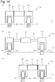
- FIG. 14 is an explanatory diagram of the operation of the moving device 10a.
- arrows indicate the rotatable directions selected by the rotatable direction switching mechanisms 60 y and 62 y for the rollers that are in contact with the support surface 4 among the rollers of the omni wheels 60 and 62.
- a case where the moving device 10a moves in the right direction will be described.
- the first and second linear motion guide mechanisms 30 and 32 are contracted, and the support surface 4 is the roller of the first and second omni wheels 60 and 62.
- the state in which the contacting roller is rotatable only in the direction corresponding to the rightward movement by the rotatable direction switching mechanisms 60y and 62y is defined as an initial state.
- the first and second linear motion guide mechanisms 30, 32 are extended.
- the first wheel unit 20a does not move in the left-right direction (lateral direction) because the left-hand movement of the omni wheel 60 is prohibited.
- the second wheel unit 22a is permitted to move the omni wheel 62 in the right direction
- the length of the second linear motion guide mechanism 32 and the length of the first linear motion guide mechanism 30 are extended. Move to the right by the sum of the lengths.
- the intermediate body 12 moves to the right by the same distance as the length of the first linear guide mechanism 30.
- the first and second linear motion guide mechanisms 30 and 32 are contracted.
- the second wheel unit 22 does not move in the lateral direction because the omni wheel 62 is prohibited from moving in the left direction. Since the first wheel unit 20 is allowed to move the omni wheel 60 in the right direction, the length of the second linear motion guide mechanism 32 is shortened and the length of the first linear motion guide mechanism 30 is shortened. Move to the right by the sum of. The intermediate body 12 moves to the right by the same distance as the contracted length of the second linear motion guide mechanism 32.
- the moving device 10a can move an arbitrary distance in the right direction.
- this rightward driving is an intermittent motion that repeats stopping and moving.
- the moving device 10a of the present embodiment has the first or third lateral movement method of the embodiment 1-1. Even in the case of using a lateral movement method corresponding to the movement method, it is possible to similarly move in the left-right direction. Further, the leftward movement is possible by setting the rotation direction permitted by the rotatable direction switching mechanisms 60y, 62y to the opposite direction.
- the operational characteristics of the mobile device 10a of the present embodiment are the same as the operational characteristics of the mobile device 10 of the embodiment 1-1.
- the rotation of the wheel body of the omni wheels 60 and 62, the expansion and contraction of the linear motion guide mechanisms 30 and 32, and the rotation direction switching permitted / prohibited by the rotatable direction switching mechanisms 60y and 62y are realized by driving with human power. Alternatively, it may be realized by driving with a driving source such as a motor. In addition to the wheels 60 and 62 shown in FIG. 13, other wheels may be provided, and auxiliary wheels that are not actively driven may be provided. A brake mechanism that prohibits passive movement, or another part having the same function as the brake may be provided.
- the rotation center axes of the wheel bodies of the two omni wheels 60 and 62 may be arranged so as to be parallel to each other and have different heights.
- the coupling unit includes an intermediate body and first and second linear motion guide mechanisms.
- the lateral movement mechanism includes (a) first and second restriction mechanisms including first and second restriction wheels, (b) first and second wheel switching mechanisms including first and second release wheels, Or (c) first and second main wheel switching mechanisms.
- Example 2-1 A mobile device 10b according to Example 2-1 will be described with reference to FIG.
- the moving device 10b according to the embodiment 2-1 differs from the moving device 10 according to the embodiment 1-1 in a configuration for switching permission / prohibition of the passive movement of the omni wheels 60 and 62 in the lateral direction.
- FIG. 15 is an explanatory diagram conceptually showing the configuration of the moving apparatus 10b of Example 2-1.
- the moving device 10b of the embodiment 2-1 has the same configuration as the moving device 10 of the embodiment 1-1, and further omni wheels 61, 63 as first and second restriction wheels.
- One switching omni wheel 61, 63 is added to each of the first and second wheel units 20b, 22b.
- the switching omni wheels 61 and 63 are rotatably supported by the main bodies 21b and 23b of the wheel units 20b and 22b.
- the switching omni wheels 61 and 63 are arranged such that the central axis of rotation of the wheel body of the switching omni wheels 61 and 63 is parallel to the front-rear direction of the moving device 10b, and in the left-right direction due to the rotation of the wheel body. Move and move back and forth with the rotation of the roller.
- the wheel units 20b and 22b are not provided with a brake mechanism for permitting / prohibiting the rotation of the rollers of the omni wheels 60 and 62. However, as the first and second regulating mechanisms, the omni wheels 61 and 63 for switching are switched. A brake mechanism (not shown) that can switch permission / prohibition of rotation of the wheel body of the omni wheels 61 and 63 is provided.
- the rotation center axes of the wheel bodies of the two omni wheels 60 and 62 are arranged coaxially in FIG. 15, but may be arranged so that they are parallel to each other and have different heights from the support surface 4.
- the two omni wheels 60 and 62 and the two switching omni wheels 61 and 63 are arranged so as to be all in contact with the support surface 4 at the same time.
- a height adjusting mechanism such as a suspension may be provided.
- Rotation of the wheel body of the omni wheels 60, 62, expansion / contraction of the linear motion guide mechanism, and switching of ON / OFF of the brake can be actively performed.
- the moving device 10b can move and turn in the front-rear direction by rotating the wheel body of the omni wheels 60 and 62.
- the moving device 10b of the present embodiment can move in the lateral direction in the same manner as the moving device 10 of the embodiment 1-1.
- the operational characteristics of the present embodiment are the same as the operational characteristics of the embodiment 1-1.
- the rotation of the wheel bodies of the omni wheels 60 and 62, the expansion and contraction of the linear motion guide mechanisms 30 and 32, and the ON / OFF switching of the brake may be realized by driving with human power or by a drive source such as a motor. It may be realized by driving.
- Other wheels may be provided in addition to the omni wheels 60 to 63 shown in FIG. 15, and auxiliary wheels that are not actively driven may be provided.
- Example 2-1 the omni wheels 60 and 62 are the first and second main wheels, and the switching omni wheels 61 and 63 are the first and second restriction wheels.
- Example 2-2 The moving device 10c of Example 2-2 will be described with reference to FIG.
- the moving device 10c according to the present embodiment is different from the moving device 10b according to the embodiment 2-1 in the configuration for switching permission / prohibition of the passive movement of the omni wheels 60 and 62 in the lateral direction.
- FIG. 16 is an explanatory diagram conceptually showing the configuration of the moving apparatus 10c of Example 2-2.
- the moving device 10c according to the embodiment 2-2 replaces the switching omni wheels 61 and 63 as first and second restriction wheels in the first and second wheel units 20c and 22c.
- the second embodiment differs from the moving device 10b of the embodiment 2-1 in that the first and second restriction mechanisms including the normal wheels 70 and 72 are provided.
- the normal wheels 70 and 72 are wheels that do not have rollers on the outer periphery and are driven in one direction when the wheels are rotated, but cannot move actively or passively in a direction crossing the driven direction.
- Ordinary wheels 70 and 72 are rotatably supported by wheel support portions 70k and 72k.
- the wheel support portions 70k and 72k and the main bodies 21c and 23c of the wheel units 20c and 22c are coupled via linear motion guide mechanisms 46 and 48 (referred to as switching linear motion guide mechanisms 46 and 48).
- the first and second restriction mechanisms cause the normal wheels 70 and 72 to actively move in the vertical direction by the expansion and contraction of the switching linear motion guide mechanisms 46 and 48 so that the normal wheels 70 and 72 are in contact with the support surface 4. It can be moved to the contact position and the retreat position away from the support surface 4.
- the normal wheels 70 and 72 are arranged in such a direction that they move in the front-rear direction when they contact the support surface 4.
- the wheel bodies of the two omni wheels 60 and 62 and the rotation center axes of the two ordinary wheels 70 and 72 are arranged coaxially in a state where they are in contact with the support surface 4 or parallel to each other and different in height.
- Rotation of the wheel body of the omni wheels 60 and 62, expansion and contraction of the linear motion guide mechanisms 30 and 32, and expansion and contraction of the switching linear motion guide mechanisms 46 and 48 can be actively performed.
- Rotating the wheel body of the omni wheels 60 and 62 enables the moving device 10c to move and turn in the front-rear direction.
- the omni wheels 60 and 62 are prohibited from moving in the left-right direction.
- the omni wheels 60 and 62 are allowed to move in the left-right direction.
- the first normal wheel 70 is in contact with the support surface 4, and the first wheel unit 20c is prohibited from moving in the left-right direction.
- the second normal wheel 72 is away from the support surface 4, and the second wheel unit 22c is in a state where movement in the left-right direction is permitted.
- the moving device 10c of the present embodiment is similar to the moving device 10 of Embodiment 1-1. It can be driven in the left-right direction using the first to third lateral movement methods.
- the moving device 10c can move in the front-rear direction and in the left-right direction at the same time, it can move in the oblique direction by simultaneously moving in the front-rear direction and the left-right direction.
- the rotation of the wheel bodies of the omni wheels 60 and 62, the expansion and contraction of the linear motion guide mechanisms 30 and 32, and the expansion and contraction of the switching linear motion guide mechanisms 46 and 48 may be realized by driving with human power, a motor, etc. It may be realized by driving with the drive source.
- Other wheels may be provided in addition to the wheels 60, 62, 70, 72 shown in FIG. 16A, and auxiliary wheels that are not actively driven may be provided.
- the wheel bodies of the omni wheels 60 and 62 may not be actively rotated, and the normal wheels 70 and 72 may be actively rotated.
- the normal wheels 70 and 72 are first and second restriction wheels, and (a) the normal wheel 70 and the switching linear motion guide mechanism 46
- the first restricting mechanism including the first directing position where the normal wheel 70 as the first restricting wheel is in contact with the support surface 4 and the support surface 4 are separated from each other by the expansion and contraction of the switching linear motion guide mechanism 46.
- the second regulating mechanism including the normal wheel 72 and the switching linear motion guide mechanism 48 can be moved to the first retracted position by the expansion and contraction of the switching linear motion guide mechanism 48.
- the normal wheel 72 which is the restriction wheel, can be moved to the second contact position in contact with the support surface 4 and the second retraction position away from the support surface 4.
- the omni wheels 60 and 62 are the first and second release wheels.
- the first wheel switching mechanism including the omni wheel 60 and the switching linear motion guide mechanism 46 is supported by the normal wheel 70 as the first main wheel by the expansion and contraction of the switching linear motion guide mechanism 46.
- the second wheel switching mechanism including the omni wheel 62 and the switching linear motion guide mechanism 48 is configured so that the second main switching mechanism 48 extends and contracts.
- the normal wheel 72 which is a wheel is separated from the support surface 4 and is a second release wheel.
- FIG. 17 is a cross-sectional view of a main part of the moving device 10t.
- the moving device 10 t of the second specific example includes first and second operation mechanisms that prohibit or permit rotation of a roller 36 s in contact with the support surface 4 among the rollers 36 of the omni wheels 60 and 62.
- the configurations of 26a and 28a are different from those of the first and second operation mechanisms 26 and 28 of the moving device 10s of the first specific example.
- the first and second operating mechanisms 26a, 28a of the moving device 10t of the second specific example are similar to the first and second operating mechanisms 26, 28 of the moving device 10s of the first specific example.
- the levers 50 and 52 are movably supported by the main bodies 21c and 23c of the wheel units 20c and 22c.
- normal wheels 70 and 72 are rotatably supported.
- the rotation center axes of the normal wheels 70 and 72 are kept parallel to the rotation center axes of the wheel bodies 34 of the first and second omni wheels 60 and 62.
- the normal wheels 70 and 72 When the first and second levers 50 and 52 are lowered, the normal wheels 70 and 72 come into contact with the support surface 4, and the normal wheels 70 and 72 support the movement of the normal wheels 70 and 72 in the direction of the rotation center axis, that is, in the left-right direction. Prohibited by friction with surface 4. When the first and second levers 50 and 52 are raised, the normal wheels 70 and 72 are separated from the support surface 4.
- the first and second omni wheels 60 and 62 and the normal wheels 70 and 72 move together. Therefore, when the normal wheels 70 and 72 contact the support surface 4 so as not to move in the left-right direction, the first and second omni wheels 60, 62 are prohibited from moving in the left-right direction. When the normal wheels 70 and 72 are away from the support surface 4, the first and second omni wheels 60 and 62 are allowed to move in the left-right direction. That is, the normal wheels 70 and 72 are linked to the movement of the first and second levers 50 and 52, and the first and second contact positions or the support surfaces that contact the support surface 4 so as not to move in the left-right direction. 4 are disposed at the first and second retracted positions apart from 4.
- the first and second omni wheels 60 and 62 are prohibited from moving in the left-right direction by lowering the first and second levers 50 and 52. By raising the second levers 50 and 52, the prohibition of movement in the left-right direction of the first and second omni wheels 60 and 62 is released. By pushing or pulling the first and second levers 50 and 52 with one of the first and second levers 50 and 52 raised, the first and second omni wheels 60 and 62 are moved left and right. Can be moved in the direction. Therefore, also in the second specific example, the moving device can be moved in the left-right direction by the same operation as the first specific example.
- the moving device is moved in the second direction (ie, the front-rear direction) in a state where movement in the left-right direction is prohibited. And the direction of the moving device can be changed.
- the normal wheels 70 and 72 can be provided outside the first and second omni wheels 60 and 62, the first and second brakes are provided inside the first and second omni wheels 60 and 62. Compared to the case, the configuration can be simplified.
- FIG. 18 is an explanatory diagram conceptually showing the configuration of the mobile device 10d of Example 2-2a.
- the moving device 10d of this embodiment is obtained by replacing the arrangement of the normal wheels 70 and 72 and the omni wheels 60 and 62 with respect to the moving device 10c of the embodiment 2-2.
- the normal wheels 70 and 72 can be actively rotated, and are supported by the main bodies 21d and 23d of the wheel units 20d and 22d so as to move in the front-rear direction by the rotation.
- the omni wheels 60 and 62 are rotatably supported by the wheel support portions 60k and 62k, and the wheel support portions 60k and 62k and the main bodies 21d and 23d of the wheel units 20d and 22d are connected via switching linear motion guide mechanisms 46 and 48. And are relatively movable.
- the switching linear motion guide mechanisms 46 and 48 can actively move the omni wheels 60 and 62 in the vertical direction, and the omni wheels 60 and 62 are brought into contact with the support surface 4 or separated from the support surface 4. Can do.
- Ordinary wheels 70 and 72 are first and second main wheels, and omni wheels 60 and 62 are first and second release wheels.
- the omni wheels 60 and 62 and the switching linear motion guide mechanisms 46 and 48 are first and second wheel switching mechanisms.
- the wheel bodies of the two omni wheels 60 and 62 and the rotation central axes of the two ordinary wheels 70 and 72 are arranged so as to be coaxial or parallel to each other and have different heights while being in contact with the support surface 4.
- Rotation of the normal wheels 70 and 72, expansion and contraction of the linear motion guide mechanisms 30 and 32, and expansion and contraction of the switching linear motion guide mechanisms 46 and 48 can be actively performed.
- the operation of the moving device 10d of the present embodiment is the same as that of the moving device 10c of the embodiment 2-2. However, the method of switching between the state in which the omni wheels 60 and 62 and the normal wheels 70 and 72 are in contact with the support surface 4 and the separated state is different.
- the omni wheels 60 and 62 are separated from the support surface 4 by contracting the switching linear motion guide mechanisms 46 and 48, and only the normal wheels 70 and 72 are grounded. In this case, the movement of each wheel unit 20d, 22d in the left-right direction is prohibited, but by rotating the normal wheels 70, 72, the moving device 10d can be moved in the front-rear direction or turned.
- the first wheel unit 20d is in a state where the normal wheel 70 is in contact with the ground and the lateral movement is prohibited, and the second wheel unit 22d Since the grounding wheel 72 is grounded and the normal wheel 72 is away from the support surface 4, the lateral movement is permitted.
- both the normal wheels 70 and 72 and the omni wheels 60 and 62 may be in contact with the support surface 4 in order to make the lateral movement of the wheel units 20d and 22d prohibited.
- the moving device 10d of the present embodiment can move and turn in the front-rear and left-right directions.
- the omni wheel 60, 62 can also move in an oblique direction.
- the rotation of the normal wheels 70 and 72, the expansion and contraction of the linear motion guide mechanisms 30 and 32, and the expansion and contraction of the switching linear motion guide mechanisms 46 and 48 may be realized by driving with human power, or a drive source such as a motor. It may be realized by driving.
- a drive source such as a motor.
- other wheels may be provided, and auxiliary wheels that are not actively driven may be provided.
- the normal wheels 70 and 72 may not be actively rotated, and the wheel bodies of the omni wheels 60 and 62 may be actively rotated.
- normal wheels arranged such that the rotation axis is parallel to the front-rear direction may be used.
- the lateral movement is permitted.
- the lateral movement is prohibited.
- the omni wheels 60 and 62 are the first and second release wheels, and (a) the omni wheel 60, the switching linear motion guide mechanism 46,
- the first wheel switching mechanism includes the normal wheel 70 as the first main wheel and the omni wheel 60 as the first release wheel supported by the expansion and contraction of the switching linear motion guide mechanism 46.
- the normal wheel 72 as the second main wheel is separated from the support surface 4 by the expansion and contraction of the switching linear motion guide mechanism 48, and the second release A second release state in which the omni wheel 62 as a wheel is in contact with the support surface 4;
- Can be a plain wheel 72 is mainly wheels to the second restricting state in contact with the support surface 4.
- the normal wheels 70 and 72 are first and second restriction wheels, and (a) the normal wheel 70 and the switching linear motion guide mechanism 46
- the first restricting mechanism including the first directing position where the normal wheel 70 as the first restricting wheel is in contact with the support surface 4 and the support surface 4 are separated from each other by the expansion and contraction of the switching linear motion guide mechanism 46.
- the second regulating mechanism including the normal wheel 72 and the switching linear motion guide mechanism 48 can be moved to the first retracted position by the expansion and contraction of the switching linear motion guide mechanism 48.
- the normal wheel 72 which is the restriction wheel, can be moved to the second contact position in contact with the support surface 4 and the second retraction position away from the support surface 4.
- FIG. 19 is an explanatory diagram conceptually showing the configuration of the mobile device 10e of Example 2-2b.
- the moving device 10e of the present embodiment is different from the moving device 10c of the embodiment 2-2 in that both the normal wheels 70 and 72 and the omni wheels 60 and 62 are switched. The difference is that they are connected to the main bodies 21e and 23e of the wheel units 20e and 22e through .about.49.
- the switching linear motion guide mechanisms 46 to 49 can actively move the omni wheels 60 and 62 and the ordinary wheels 70 and 72 in the vertical direction, and the omni wheels 60 and 62 and the ordinary wheels 70 and 72 on the support surface 4. They can be brought into contact or separated from the support surface 4. Both or one of the wheel bodies of the omni wheels 60 and 62 and the normal wheels 70 and 72 can be actively rotated. If the wheels are not actively rotated, they can be passively rotated.
- the directions of the normal wheels 70 and 72 and the omni wheels 60 and 62 are the same as those in the embodiment 2-2.
- the wheel bodies of the two omni wheels 60 and 62 and the rotation central axes of the two ordinary wheels 70 and 72 are arranged so as to be coaxial or parallel to each other and have different heights while being grounded to the support surface 4.
- Rotation of both or one of the omni wheels 60 and 62 and the normal wheels 70 and 72, expansion and contraction of the linear motion guide mechanisms 30 and 32, and expansion and contraction of the switching linear motion guide mechanisms 46 to 49 can be performed actively. .
- the operation of the moving device 10e of the present embodiment is the same as that of the moving device 10c of the embodiment 2-2. However, the method of switching between the state in which the omni wheels 60 and 62 and the normal wheels 70 and 72 are in contact with the support surface 4 and the separated state is different.
- the normal wheels 70 and 72 when the normal wheels 70 and 72 are grounded, the normal wheels 70 and 72 are grounded by extending the switching linear motion guide mechanisms 46 and 48 to which the normal wheels 70 and 72 are connected.
- the omni wheels 60 and 62 are separated from the support surface 4 by contracting the switching linear motion guide mechanisms 47 and 49 to which the wheels 60 and 62 are connected.
- both the normal wheels 70 and 72 and the omni wheels 60 and 62 are in contact with the support surface 4 so that the lateral movement of the first and second wheel units 20e and 22e is prohibited. Also good.
- the omni wheels 60 and 62 when the omni wheels 60 and 62 are brought into contact with the support surface 4, the omni wheels 60 and 62 are extended by extending the switching linear motion guide mechanisms 47 and 49 to which the omni wheels 60 and 62 are connected.
- the normal wheels 70 and 72 are separated from the support surface 4 by being grounded and contracting the switching linear motion guide mechanisms 46 and 48 to which the normal wheels 70 and 72 are connected. In this case, in each wheel unit 20e, 22e, only the omni wheels 60, 62 are in contact with the support surface 4, and the movement of the wheel units 20e, 22e in the left-right direction is permitted.
- the second wheel unit 22e is in a state in which lateral movement is prohibited because the normal wheel 72 is in contact with the ground, and the first wheel unit 20e has the omni wheel 60. Since only is grounded, lateral movement is permitted.
- Ordinary wheels 70 and 72 are first and second restriction wheels, and omni wheels 60 and 62 are first and second main wheels.
- the normal wheels 70 and 72 and the switching linear motion guide mechanisms 46 to 49 are first and second restricting mechanisms. From another viewpoint, the normal wheels 70 and 72 are the first and second main wheels, and the omni wheels 60 and 62 are the first and second release wheels.
- the omni wheels 60 and 62 and the switching linear motion guide mechanisms 46 to 49 are first and second wheel switching mechanisms.
- the moving device 10e of this embodiment can move and turn in the front-rear and left-right directions.
- the omni wheel 60, 62 can also move in an oblique direction.
- Rotation of both or one of the wheel bodies of the normal wheels 70 and 72 and the omni wheels 60 and 62, expansion and contraction of the linear motion guide mechanisms 30 and 32, and expansion and contraction of the switching linear motion guide mechanisms 46 to 49 are driven by human power. It may be realized by driving with a driving source such as a motor. In addition to the wheels 60, 62, 70, and 72 shown in FIG. 19A, other wheels may be provided, and auxiliary wheels that are not actively driven may be provided.
- each of the wheel units 20e and 22e has a horizontal axis in a state in which the normal wheels arranged so that the rotation axis is parallel to the front-rear direction are in contact with the support surface 4 and the normal wheels 70 and 72 are separated from the support surface 4.
- the lateral direction Movement is prohibited.
- the omni wheels 60 and 62 are the first and second release wheels, and (a) the omni wheel 60 and the switching linear motion guide mechanism 46,
- the first wheel switching mechanism including the switching linear motion guide mechanisms 46, 47 is separated from the support surface 4 by the expansion and contraction of the switching linear motion guide mechanisms 46, 47, and the omni as the first release wheel.
- a first release state in which the wheel 60 is in contact with the support surface 4 and a first restricted state in which the normal wheel 70 that is the first main wheel is in contact with the support surface 4 can be achieved.
- the normal wheels 70 and 72 are first and second restriction wheels, and (a) the normal wheel 70 and the switching linear motion guide mechanism 46, 47, the first contact position where the normal wheel 70 which is the first restriction wheel is in contact with the support surface 4 by the expansion and contraction of the switching linear motion guide mechanisms 46, 47, and the support surface
- the second regulating mechanism including the normal wheel 72 and the switching linear motion guide mechanisms 48 and 49 is the switching linear motion guide mechanism 48. 49, the normal wheel 72 as the second restriction wheel can be moved to the second contact position in contact with the support surface 4 and the second retraction position away from the support surface 4.
- FIG. 20 is an explanatory diagram conceptually showing the configuration of the moving apparatus 10f of the embodiment 2-3.
- each wheel unit 20f, 22f has normal wheels 70, 72 and omni wheels 60, 62, as in the embodiment 2-2b.
- the switching method is different from that in Example 2-2b.
- the normal wheels 70 and 72 are supported by the rotating members 24f and 26f, and the rotating members 24f and 26f are connected to the main bodies 21f and 23f of the wheel units 20f and 22f via the rotating joints 25 and 27, respectively. Is bound to.
- the normal wheels 70 and 72 are arranged to move in the front-rear direction when rotated in a grounded state, and can be actively rotated.
- the rotation axes of the rotary joints 25 and 27 are parallel to the front-rear direction, and the rotary members 24f and 26f can be actively rotated.
- omni wheels 60 and 62 are rotatably supported by the rotating members 24f and 26f.
- the direction of the omni wheels 60 and 62 is a direction in which the rotation axis of the wheel body is perpendicular to the front-rear direction.
- the configurations of the intermediate body 12 and the linear motion guide mechanisms 30 and 32 are the same as those in Example 2-2b.
- the rotation center axes of the two ordinary wheels 70 and 72 are arranged so as to be coaxial when the ordinary wheels 70 and 72 are grounded, but may be arranged so as to be parallel to each other and have different heights.
- the rotation center axes of the wheel bodies of the omni wheels 60 and 62 are arranged so as to be in the same plane as the rotation center axes of the ordinary wheels 70 and 72.
- Rotation of the normal wheels 70 and 72, expansion and contraction of the linear motion guide mechanisms 30 and 32, and rotation of the rotary members 24f and 26f around the rotary joints 25 and 27 can be performed actively.
- FIG. 20B shows a state in which the normal wheel 70 is grounded in the first wheel unit 20f and the omni wheel 62 is grounded in the second wheel unit 22f.
- the moving device of the present embodiment can achieve the embodiment 2-2b.
- the horizontal movement is possible.
- Ordinary wheels 70 and 72 are first and second main wheels, and omni wheels 60 and 62 are first and second release wheels.
- the omni wheels 60 and 62 and the rotary joints 25 and 27 are first and second wheel switching mechanisms.
- the normal wheels 70 and 72 are first and second restriction wheels, and the omni wheels 60 and 62 are first and second main wheels.
- the normal wheels 70 and 72 and the rotary joints 25 and 27 are first and second restriction mechanisms.
- the moving device 10f of this embodiment can move and turn in the front-rear and left-right directions.
- the omni wheel 60, 62 can also move in an oblique direction.
- the rotation of the normal wheels 70 and 72, the expansion and contraction of the linear motion guide mechanisms 30 and 32, and the rotation of the rotation members 24f and 26f around the rotation joints 25 and 27 may be realized by driving with human power, a motor, etc. It may be realized by driving with the drive source.
- other wheels may be provided, or auxiliary wheels that are not actively driven may be provided.
- the normal wheels 70 and 72 may not be actively rotated, and the wheel bodies of the omni wheels 60 and 62 may be actively rotated.
- each of the wheel units 20f and 22f is arranged in the horizontal direction when the normal wheels arranged so that the rotation axis is parallel to the front-rear direction are in contact with the support surface 4 and the normal wheels 70 and 72 are separated from the support surface 4.
- the lateral direction Movement is prohibited.
- the first wheel unit 20f has the omni wheel 60 on the right side of the normal wheel 70, but may have the omni wheel 60 on the left side, and the second wheel unit 22f has the normal wheel 72. Although there is an omni wheel 62 on the left side, the omni wheel 62 may be on the right side.
- the omni wheels 60 and 62 are the first and second release wheels, and (a) a first including the omni wheel 60 and the rotary joint 25.
- the ordinary wheel 70 that is the first main wheel is separated from the support surface 4 by the rotation of the rotary joint 25, and the omni wheel 60 that is the first release wheel is in contact with the support surface 4.
- the rotation of the rotary joint 27 causes the ordinary wheel 72 as the second main wheel to move away from the support surface 4, and the omni wheel 62 as the second release wheel contacts the support surface 4.
- the release state and the second main wheel Can be the second restricting state of the passing wheel 72 is in contact with the support surface 4.
- the ordinary wheels 70 and 72 are the first and second restriction wheels, and (a) the first wheel including the ordinary wheel 70 and the rotary joint 25.
- the restriction mechanism moves the ordinary wheel 70 as the first restriction wheel to the first contact position in contact with the support surface 4 and the first retraction position away from the support surface 4 by the rotation of the rotary joint 25.
- the second restricting mechanism including the ordinary wheel 72 and the rotary joint 27 is configured so that the ordinary wheel 72 as the second restricting wheel is brought into contact with the support surface 4 by the rotation of the rotary joint 27. 2 and a second retreat position away from the support surface 4.
- FIG. 21 is an explanatory diagram conceptually showing the configuration of a moving apparatus 10g according to a modification.
- ordinary wheels 70 and 72 and left sides of ordinary wheels 70 and 72 are connected to rotating members 24g and 26g coupled to main bodies 21g and 23g of wheel units 20g and 22g via rotating joints 25 and 27, respectively.
- the omni wheels 60, 62, 64, 66 arranged on both the right side and the right side may be rotatably supported.
- FIG. 22 is an explanatory diagram conceptually showing the configuration of the moving apparatus 10h of the embodiment 2-4.
- the moving device 10h of the present embodiment has substantially the same configuration as the moving device 10f of Embodiment 2-3, but rotational joints 25 and 27 are attached to the main bodies 21h and 23h of the wheel units 20h and 22h.
- the two omni wheels 60, 64; 62, 66 are disposed on the rotating members 24h, 26h coupled to each other, and the rotation shaft of the wheel body of the omni wheels 60, 62, 64, 66 is the moving device 10h.
- the unidirectional rotation mechanism 60x, 62x, 64x, 66x is provided on the wheel body of the omni wheels 60, 62, 64, 66.
- the one-way rotation mechanism 60x, 62x, 64x, 66x is a one-way clutch (one-way clutch), a ratchet mechanism, or the like, and permits rotation in one direction and prohibits rotation in the opposite direction.
- the rotatable direction of the wheel body of each omni wheel 60, 62, 64, 66 is the direction indicated by the arrow in FIG. That is, in each of the rotating members 24h and 26h, the omni wheels 64 and 62 arranged on the left side can be rotated in the direction of moving to the left when grounded, and the omni wheels 60 and 66 arranged on the right side. Can rotate in a direction to move to the right when grounded.
- the rotation center axes of the two normal wheels 70 and 72 are arranged coaxially, but may be arranged so as to be parallel to each other and have different heights.
- the omni wheels 60 and 66 on the right side of the rotating members 24h and 26h are grounded, and when moved to the left side, the omni wheel on the left side of the rotating members 24h and 26h. 64 and 62 are grounded.
- the rotary joints 25 and 27 of the rotary members 24h and 26h may be actively moved, but a force for rotating the rotary members 24h and 26h is generated as the linear motion guide mechanisms 30 and 32 expand and contract.
- the rotary joints 25 and 27 need not be moved actively.
- the normal wheels 70 and 72 are grounded, if the linear motion guide mechanisms 30 and 32 are expanded and contracted to move the main bodies 21h and 23h of the wheel units 20h and 22h to the right or left, the normal wheels 70 and 72 are left and right. Since it does not move in the direction, a movement for rotating the rotary members 24h and 26h around the rotary joints 25 and 27 occurs.
- the wheel bodies of the omni wheels 60 and 66 can rotate.
- the omni wheels 60 and 66 move in the right direction. If the omni wheels 60 and 66 on the right side of the rotating members 24h and 26h are grounded and the main bodies 21h and 23h of the wheel units 20h and 22h move to the left, the wheel bodies of the omni wheels 60 and 66 are prohibited from rotating. The movement of rotating the rotary members 24h and 26h around the rotary joints 25 and 27 occurs, and the normal wheels 70 and 72 return to the grounded state.
- Rotation of the normal wheels 70 and 72 and expansion and contraction of the linear motion guide mechanisms 30 and 32 can be performed actively.
- the moving device 10 h can move in the front-rear direction and turn by driving the normal wheels 70 and 72.
- the state in which the omni wheels 60 and 66 on the right side of the rotating members 24h and 26h are grounded is the same as the state in which the rotatable direction switching mechanism permits the rightward movement in Example 1-2. Can move to the right in the same way as 2.
- the left omni wheels 64 and 62 on the left side of the rotating members 24h and 26h can move leftward.
- Ordinary wheels 70 and 72 are first and second main wheels, and omni wheels 60 and 64; 62 and 66 are first and second release wheels.
- the omni wheels 60, 64; 62, 66 and the rotary joints 25, 27 are first and second wheel switching mechanisms.
- the normal wheels 70 and 72 are the first and second restriction wheels, and the omni wheels 60 and 64; 62 and 66 are the first and second main wheels.
- the normal wheels 70 and 72 and the rotary joints 25 and 27 are first and second restriction mechanisms.
- the moving device 10h according to the present embodiment can move back and forth, turn left and right, and turn.
- the rotation of the normal wheels 70 and 72 and the expansion and contraction of the linear motion guide mechanisms 30 and 32 may be realized by driving with human power or may be realized by driving with a driving source such as a motor.
- the rotation of the rotary members 24h and 26h around the rotary joints 25 and 27 may be passively rotated along with the expansion and contraction of the linear motion guide mechanisms 30 and 32, or driven by a driving source such as a motor even if driven by human power. May be.
- other wheels may be provided, and auxiliary wheels that are not actively driven may be provided.
- normal wheels arranged so that the rotation axis is parallel to the front-rear direction may be used.
- the lateral movement is permitted.
- the lateral movement is prohibited.
- the omni wheels 60, 62, 64 and 66 are the first and second release wheels, and (a) the omni wheels 60 and 64 and the rotary joint.
- the ordinary wheel 70 that is the first main wheel is separated from the support surface 4 by the rotation of the rotary joint 25, and the omni wheel 60 or 64 that is the first release wheel is supported.
- Or 66 is in contact with the support surface 4
- a second release state that can be a second plain wheel 72 is mainly wheels to the second restricting state in contact with the support surface 4.
- the normal wheels 70, 72 are first and second restriction wheels, and (a) the normal wheel 70, the rotary joint 25,
- the first restricting mechanism includes a first contact position where the ordinary wheel 70 which is the first restricting wheel is in contact with the support surface 4 and a first retreat away from the support surface 4 by the rotation of the rotary joint 25.
- the second restricting mechanism including the ordinary wheel 72 and the rotary joint 27 causes the ordinary wheel 72, which is the second restricting wheel, to be supported by the rotation of the rotary joint 27. 4 can be moved to a second contact position in contact with 4 and a second retracted position away from the support surface 4.
- FIG. 23 is an explanatory diagram conceptually showing the structure of the mobile apparatus 10i in the embodiment 2-5.
- the moving device 10i of the present embodiment is close to the configuration of the moving device 10c of the embodiment 2-2, but the one connected to the normal wheels 70 and 72 is the switching linear motion guide mechanism 46. , 48, but the rotary joints 76, 78 are different.
- the normal wheels 70 and 72 are in contact with the support surface 4 and can be turned around the vertical axis by the rotary joints 76 and 78, and the moving direction can be switched to various directions such as front and rear, left and right, and diagonal.
- the rotation center axes of the wheel bodies of the two omni wheels 60 and 62 are arranged coaxially, but may be arranged so as to be parallel to each other and have different heights.
- the rotation center axes of the ordinary wheels 70 and 72 are coaxial or parallel to the rotation center axes of the wheel bodies of the omni wheels 60 and 62 and have different heights when the movement direction of the ordinary wheels 70 and 72 is the front-rear direction.
- the two omni wheels 60, 62 and the two ordinary wheels 70, 72 are all arranged to be grounded simultaneously.
- a height adjusting mechanism such as a suspension may be provided.
- Rotation of the omni wheels 60 and 62, expansion and contraction of the linear motion guide mechanisms 30 and 32, and rotation of the rotary joints 76 and 78 can be actively performed.
- the omni wheels 60 and 62 can be driven to move and turn in the front-rear direction.
- the wheel units 20i and 22i are prohibited from moving in the lateral direction because they cannot be moved in the left-right direction either actively or passively.
- the moving direction of the normal wheels 70 and 72 is the left-right direction, the lateral movement of the wheel units 20i and 22i is permitted. Therefore, by switching the direction of the normal wheels 70 and 72, the moving device 10i of the present embodiment can move in the lateral direction in the same manner as the moving device 10 of the embodiment 1-1.
- Ordinary wheels 70 and 72 are first and second restriction wheels, and omni wheels 60 and 62 are first and second main wheels.
- the normal wheels 70 and 72 and the rotary joints 76 and 78 are first and second regulating mechanisms.
- the moving device 10i of the present embodiment can move and turn in the front-rear and left-right directions. If the direction of the normal wheels 70 and 72 is appropriately adjusted according to the moving direction of the moving device 10i, the moving in the oblique direction is also possible.
- the rotation of the wheel bodies of the omni wheels 60 and 62, the expansion and contraction of the linear motion guide mechanisms 30 and 32, and the rotation of the rotary joints 76 and 78 may be realized by driving with human power, or by a drive source such as a motor. It may be realized by driving.
- a drive source such as a motor. It may be realized by driving.
- other wheels may be provided, and auxiliary wheels that are not actively driven may be provided.
- the omni wheels 60 and 62 are first and second main wheels, and the normal wheels 70 and 72 are first and second restriction wheels.
- the first restricting mechanism including the ordinary wheel 70 and the rotation joint 76 causes the rotation of the rotation joint 76 to change the direction of the ordinary wheel 70 that is the first restriction wheel in the first direction while contacting the support surface 4. It is possible to switch between a first direction in which movement is possible and a second direction in which movement in the second direction is possible while contacting the support surface 4.
- the second restricting mechanism including the ordinary wheel 72 and the rotation joint 78 causes the rotation of the rotation joint 78 to change the direction of the ordinary wheel 72 that is the second restriction wheel in the first direction while contacting the support surface 4. It is possible to switch between the third direction in which the movement is possible and the fourth direction in which the movement in the second direction is possible while being in contact with the support surface 4.
- FIG. 24 is an explanatory diagram conceptually showing the configuration of the moving apparatus 10j of the embodiment 2-6.
- the wheel units 20j and 22j are each provided with two omni wheels 60, 64; 62, 66, and the omni wheels 60, 62, 64, 66 is coupled to the main bodies 21j and 23j of the wheel units 20j and 22j via the switching linear motion guide mechanisms 46 to 49.
- the switching linear motion guide mechanisms 46 to 49 can actively move the omni wheels 60, 62, 64, 66 in the vertical direction, and ground the omni wheels 60, 62, 64, 66 to the support surface 4. It can be separated from the support surface 4.
- the rollers of the omni wheels 60, 62, 64, 66 are provided with unidirectional rotation mechanisms 60x, 62x, 64x, 66x, and the rotatable direction of the rollers is limited to one direction.
- a one-way clutch one-way clutch
- a ratchet mechanism or the like may be used for the one-way rotation mechanisms 60x, 62x, 64x, 66x.
- the arrow indicates the direction in which the roller in contact with the support surface 4 can rotate.
- One omni wheel 60, 66 of each wheel unit 20j, 22j can rotate in a direction in which it can move rightward when grounded, and the other omni wheel 64, 62 is directed leftward when grounded.
- the roller can rotate in a direction in which it can move.
- the two types of omni wheels 60, 66; 64, 62 in which the rollers rotate in directions opposite to each other may be arranged on either the left side or the right side in each wheel unit 20j, 22j. Other configurations are the same as those of Example 2-1.
- the rotation center axes of the wheel bodies of the four omni wheels 60, 62, 64, 66 are arranged so as to be coaxial when grounded, but may be arranged so as to be parallel to each other and have different heights.
- Rotation of the wheel body of the omni wheels 60, 62, 64, 66, expansion and contraction of the linear motion guide mechanisms 30 and 32, and expansion and contraction of the switching linear motion guide mechanisms 46 to 49 can be performed actively.
- the operation of the mobile device 10j according to the present embodiment will be described.
- either one of the omni wheels 60 and 66 movable in the right direction and the omni wheels 64 and 62 movable in the left direction is grounded, and the other is separated from the support surface 4.
- the direction in which the wheel unit 20j can move can be switched to the right direction or the left direction.
- the moving apparatus 10j of the present embodiment can move in the horizontal direction in the same manner as the moving apparatus 10a of the embodiment 1-2.
- both the omni wheels 60 and 66 that can move in the right direction of the wheel units 20j and 22j and the omni wheels 64 and 62 that can move in the left direction are grounded simultaneously, the wheel units 20j and 22j are prohibited from moving in the left-right direction. It will be in the state.
- the moving device 10j is moved in the front-rear direction or turned, passive movement in the left-right direction is constrained by setting the wheel units 20j, 22j to be inhibited from moving in the left-right direction.
- the omni wheels 60 and 64 are one side wheel and the other side wheel of the first main wheel.
- the omni wheels 62 and 66 are one side wheel and the other side wheel of the second main wheel.
- the first main wheel switching mechanism including the switching linear motion guide mechanisms 46 and 47 one of the omni wheels 60 and 64, which are the first main wheels, is supported by the expansion and contraction of the switching linear motion guide mechanisms 46 and 47. 4 is switched between a first state in which the other is in contact with the support surface 4 and a second state in which the other is in contact with the support surface 4 and one is away from the support surface 4.
- the second main wheel switching mechanism including the switching linear motion guide mechanisms 48 and 49
- one of the omni wheels 62 and 66 as the second main wheels is supported by the expansion and contraction of the switching linear motion guide mechanisms 48 and 49. 4 is switched between a third state where the other is in contact with the support surface 4 and the other is in contact with the support surface 4 and one is away from the support surface 4.
- the moving device 10j of this embodiment can move and turn in the front-rear and left-right directions. Moreover, the movement of the diagonal direction is possible.
- the rotation of the wheel bodies of the omni wheels 60, 62, 64, and 66, the expansion and contraction of the linear motion guide mechanisms 30 and 32, and the expansion and contraction of the switching linear motion guide mechanisms 46 to 49 may be realized by driving with human power. However, it may be realized by driving with a driving source such as a motor. Other wheels may be provided in addition to the wheels shown in FIG. 24, and auxiliary wheels that are not actively driven may be provided.
- the switching linear motion guide mechanisms 46 to 49 provided in the second group of moving devices 10c, 10d, 10e, and 10j may be replaced with rotary joints whose rotation axes are directions other than the vertical direction.
- the omni wheels 60 and 62 and the ordinary wheels 70 and 72 or the omni wheels 64 and 66 may be configured to switch between the grounded state and the separated state by the rotation around the rotary joint.
- the omni wheels 60 and 62 and the ordinary wheels 70 and 72 or the omni wheels 64 and 66 are configured to switch between a state of being grounded to the support surface 4 and a state of being separated from the support surface 4, a plurality of joints are combined. May be.
- the coupling unit includes an intermediate body and first and second linear motion guide mechanisms, and the first and second main wheels are movable only in the second direction while contacting the support surface, First and second main wheel moving mechanisms are provided as lateral movement mechanisms.
- FIG. 25A is an explanatory diagram conceptually showing the configuration of the mobile device of the embodiment 3-1.
- the moving device 10k of the present embodiment has the main bodies 21k, 23k of the wheel units 20k, 22k so that the normal wheels 70, 72 as the main wheels can move in the front-rear direction. Is supported rotatably.
- the second members of the linear motion guide mechanisms 30 and 32 are respectively fixed to the main bodies 21k and 23k of the first and second wheel units 20k and 22k, and the first members of the linear motion guide mechanisms 30 and 32 are the rotary joints 14 and 16, respectively.
- the rotation axes of the first and second rotary joints 14 and 16 are parallel to the front-rear direction and can be actively rotated.
- the wheel units 20k and 22k are lifted by the rotation of the rotary joints 14 and 16, and the normal wheels 70 and 72 are separated from the support surface 4.
- the first rotary joint 14 moves the normal wheel 70 that is the first main wheel to a first contact position that is in contact with the support surface 4 and a first retreat position that is away from the support surface 4. It is a main wheel moving mechanism.
- the second rotary joint 16 moves the normal wheel 72, which is the second main wheel, to the second contact position in contact with the support surface 4 and the second retreat position away from the support surface 4. It is a main wheel moving mechanism.
- the normal wheels 70 and 72 can move only in the second direction while contacting the support surface 4.
- Omni wheels 64 are arranged in the intermediate body 12k.
- the omni wheel 64 is arranged in such a direction that it moves in the front-rear direction by the rotation of the wheel body and moves in the lateral direction by the rotation of the roller.
- the omni wheel 64 is an intermediate wheel that can move in the first direction and the second direction while contacting the support surface 4.
- the first and second normal wheels 70 and 72 and the omni wheel 64 can be grounded at the same time.
- the rotation center axes of the two normal wheels 70 and 72 and the rotation center axis of the wheel body of the omni wheel 64 are always arranged in the same plane.
- Rotation of the normal wheels 70 and 72, expansion and contraction of the linear motion guide mechanisms 30 and 32, and rotation of the rotary joints 14 and 16 can be actively performed.
- the moving device 10k By rotating the first and second ordinary wheels 70 and 72, the moving device 10k can move and turn in the front-rear direction.
- FIG. 26 and 27 are explanatory diagrams of the operation of the moving device 10k.
- a lateral movement method when the first and second linear motion guide mechanisms 30 and 32 are simultaneously expanded and contracted will be described.
- the first and second linear motion guide mechanisms 30 and 32 are contracted, and the first and second ordinary wheels 70 and 72 and the omni wheel 64 are all grounded. Is the initial state.
- the second rotary joint 16 is rotated to move the second ordinary wheel 72 to the second retreat position away from the support surface 4.
- the horizontal position of the center of gravity G of the moving device 10k and the user is set between the first normal wheel 70 and the omni wheel 64.
- the first and second linear motion guide mechanisms 30 and 32 are extended as shown in FIG. Since the first wheel unit 20k is grounded via the normal wheel 70, it does not move in the lateral direction. Since the intermediate body 12k is grounded via the omni wheel 64, the intermediate body 12k moves to the right by the same distance as the length of the first linear motion guide mechanism 30 extended. Also during this time, the state in which the horizontal position of the center of gravity G of the moving device 10k and the user is between the first ordinary wheel 70 and the omni wheel 64 is maintained.
- the second rotary joint 16 is rotated to move the second ordinary wheel 72 to the second contact position in contact with the support surface 4, and to ground.
- the first rotary joint 14 is rotated to move the first ordinary wheel 70 to the first retreat position away from the support surface 4.
- the position of the center of gravity G in the left-right direction is between the second normal wheel 72 and the omni wheel 64.
- the first and second linear motion guide mechanisms 30 and 32 are contracted as shown in FIG. Since the second wheel unit 22k is grounded via the normal wheel 72, it does not move in the lateral direction. Since the intermediate body 12k is grounded via the omni wheel 64, the intermediate body 12k moves to the right by the same distance as the contracted length of the second linear motion guide mechanism 32.
- the state in which the lateral position of the center of gravity G exists between the second ordinary wheel 72 and the omni wheel 64 is maintained.
- the first rotary joint 14 is rotated to bring the first ordinary wheel 70 into the first contact position in contact with the support surface 4. Move and ground.
- the moving device 10k can move an arbitrary distance in the right direction.
- this rightward movement is an intermittent motion that repeats stopping and moving.
- first and second linear motion guide mechanisms 30 and 32 are simultaneously expanded and contracted, and is a method corresponding to the second lateral movement method described in the embodiment 1-1.
- the first and second linear motion guide mechanisms 30 and 32 are separately expanded and contracted, whereby the moving device 10k of the present embodiment is continuously provided. It can move in the horizontal direction.
- the moving device 10k can move back and forth and turn left and right. If the wheel body of the omni wheel 64 can be actively rotated, it can be moved in an oblique direction.
- the rotation of the normal wheels 70 and 72, the expansion and contraction of the linear motion guide mechanisms 30 and 32, and the rotation of the rotary joints 14 and 16 may be realized by being driven by human power, or may be driven by a driving source such as a motor. It may be realized.
- a driving source such as a motor.
- other wheels may be provided, and auxiliary wheels that are not actively driven may be provided.
- Rotation of the wheel body of the omni wheel 64 may be actively rotated or may be passively supported so as to be freely rotatable.
- the omni wheel 64 may be arranged in a direction different from the direction in which the omni wheel 64 moves in the front-rear direction by the rotation of the wheel body and moves in the lateral direction by the rotation of the roller.
- the movement of the center of gravity G is realized by a method in which the user tilts the body, a method having a mass, or a method in which a part or all of the user's body is moved to the right or left.
- the omni wheel 64 connected to the intermediate body 12k is provided with a mechanism for moving the omni wheel 64 relative to the right side or the left side with respect to the intermediate body 12k. You may adjust so that it may be located between the 1st or 2nd normal wheel 70 and 72 and the omni wheel 64.
- FIG. Alternatively, the auxiliary wheel described above is provided so that the point where the center of gravity G is projected onto the support surface 4 without moving the center of gravity G is always present inside the polygon formed by the ground contact point of the wheel. Also good.
- the rotation joints 14 and 16 only need to be able to separate the normal wheels 70 and 72 from the support surface 4 by the rotation thereof, and instead of connecting the linear motion guide mechanisms 30 and 32 and the intermediate body 12k, the rotation units 14 and 16 have the wheel units 20k and 22k.
- the main bodies 21k and 23k and the linear motion guide mechanisms 30 and 32 may be coupled, or the main bodies 21k and 23k of the wheel units 20k and 22k and the wheel support portions may be coupled.
- the positions of the rotary joints 14 and 16 are separated from the support surface 4 when the normal wheels 70 and 72 are grounded to the support surface 4 without causing the normal wheels 70 and 72 to interfere with the support surface 4 and the like. As long as the state can be switched smoothly, the mobile device 10k may be disposed anywhere.
- the rotation axis of the rotary joint may be a direction other than the vertical direction.
- the rotation axes of the rotation joints 15 and 17 may be parallel to the left-right direction.
- the omni wheel 64 may be a wheel that can move only in the left-right direction when grounded. In such a state, a wheel that cannot move in the front-rear direction may be used. That is, the omni wheel 64 is not an omni wheel but may be a normal wheel that can move only in the left-right direction (the normal wheel that can move only in the left-right direction is grounded to the support surface 4 when moving left and right, but is supported when moving back and forth. Away from surface 4).
- FIG. 28 is an explanatory diagram conceptually showing the configuration of the moving apparatus of the embodiment 3-2.
- the moving device 10m of the present embodiment is similar to the moving device 10k of the embodiment 3-1, but does not have the rotary joints 14 and 16, and the linear motion guide mechanisms 30 and 32 The difference is that the intermediate body 12m is coupled, and the omni wheel 64 is connected to the intermediate body 12m via the switching linear motion guide mechanism 45.
- the rotation center axes of the wheel bodies of the two normal wheels 70 and 72 and the omni wheel 64 are arranged so as to be coaxial or parallel to each other and have different heights while being grounded to the support surface 4.
- Rotation of the normal wheels 70 and 72, expansion and contraction of the linear motion guide mechanisms 30 and 32, and expansion and contraction of the switching linear motion guide mechanism 45 can be actively performed.
- the moving device 10m of this embodiment By rotating the first and second normal wheels 70 and 72, the moving device 10m can move and turn in the front-rear direction.
- the switching linear motion guide mechanism 45 to which the omni wheel 64 is connected is extended so that the omni wheel 64 protrudes downward from the two normal wheels 70 and 72.
- the center of gravity of the moving device 10m or the user hereinafter simply referred to as the center of gravity
- the moving device 10m is tilted, the first ordinary wheel 70 and the omni wheel 64 are grounded, and the second The normal wheel 72 is separated from the support surface 4.
- the center of gravity is moved to the right, the second ordinary wheel 72 and the omni wheel 64 are brought into contact with the ground, and the first ordinary wheel 70 is separated from the support surface 4.
- the moving device 10m of the present embodiment can move in the lateral direction in the same manner as the moving device 10k of the embodiment 3-1.
- the first and second main wheel moving mechanisms include a switching linear motion guide mechanism 45 and a mechanism (not shown) that moves the center of gravity to the right or left side (for example, a mechanism that moves the center of gravity to the right or left side, or an intermediate body).
- a user who rides on 12 m moves the center of gravity to the right side or the left side).
- the first ordinary wheel 70 is a first main wheel that can move only in the second direction while being in contact with the support surface 4.
- the second ordinary wheel 72 is a second main wheel that can move only in the second direction while contacting the support surface 4.
- the moving device 10m of the present embodiment can move and turn in the front-rear and left-right directions. If the wheel body of the omni wheel 64 can be actively rotated, it can be moved in an oblique direction.
- the rotation of the normal wheels 70 and 72, the expansion and contraction of the linear motion guide mechanisms 30 and 32, and the expansion and contraction of the switching linear motion guide mechanism 45 may be realized by being driven by human power or driven by a drive source such as a motor. May be realized.
- Other wheels may be provided in addition to the wheels 64, 70, and 72 shown in FIG. 28A, and auxiliary wheels that are not actively driven may be provided.
- the center-of-gravity movement can be realized by a method in which the user tilts the body, a method having a mass, or a method in which a part or all of the user's body is moved to the right or left.
- a mechanism for moving the omni wheel 64 to the right or left side relative to the intermediate body 12m is provided, so that the left and right positions of the center of gravity are adjusted to the normal wheels 70 and 72 and the omni wheel. 64 may be adjusted so that the moving device 10m is tilted when the switching linear motion guide mechanism 45 is extended.
- the wheel units 20n and 22n are provided with switching linear motion guide mechanisms 46 and 48, and the ordinary wheels 70 and 72 are moved up and down without moving the omni wheel 64 up and down. It may be configured. Moreover, the structure which moves both the omni wheel 64 and the normal wheels 70 and 72 up and down separately may be sufficient.
- the switching linear motion guide mechanisms 45; 46, 48 are coupled to the wheel support portion 64k and the intermediate body 12m of the omni wheel 64, or the wheel support portions 70k and 72k of the normal wheels 70 and 72 and the wheel unit 20n.
- the wheel units 20m and 22m; 20n and 22n and the linear motion guide mechanisms 30 and 32, or the intermediate bodies 12m and 12n and the linear motion guide mechanisms 30 and 32 may be used.
- the switching linear motion guide mechanisms 46 and 48 are contracted so that the normal wheels 70 and 72 are supported on the support surface 4.
- the operation of adjusting so that the point where the center of gravity is always projected onto the support surface is always present inside the polygon formed by the ground contact point of the wheel as in Example 3-1.
- the omni wheel 64 may be a wheel that can move only in the left-right direction when grounded. In such a state, a wheel that cannot move in the front-rear direction may be used. That is, the omni wheel 64 is not an omni wheel but may be a normal wheel that can move only in the left-right direction (the normal wheel that can move only in the left-right direction is grounded to the support surface 4 when moving left and right, but is supported when moving back and forth. Away from surface 4).
- the switching linear motion guide mechanisms 45, 46, 48 or the rotary joints 14-17 provided as the first and second main wheel switching mechanisms are the normal wheels 70, 72.
- the omni wheel 64 and the omni wheel 64 may be interchanged, one or both of them may be arranged, and may be arranged anywhere in the moving device and in any direction. Good.
- FIG. 29 is an explanatory diagram conceptually showing the structure of a mobile device 10p of Embodiment 4.
- Example 4 is an example of a structure without an intermediate.
- the moving device 10p of the present embodiment is close to the configuration of the moving device 10 of the embodiment 1-1, but has no intermediate body, and has one linear motion guide mechanism 31.
- the point that the linear motion guide mechanism 31 couples the two wheel units 20p and 22p is different from the moving device of the embodiment 1-1.
- the linear motion guide mechanism 31 is a coupling unit, and the first wheel unit 20p and the second wheel unit 22p can be moved toward and away from each other in the first direction. And the second wheel unit 22p.
- a guide mechanism other than the linear motion guide mechanism, a link mechanism, a joint (joint), or the like may be used.
- the operation of the moving device 10p of this embodiment will be described.
- the wheel body of the first and second omni wheels 60 and 62 can be rotated and turned in the front-rear direction. Since the rollers of the omni wheels 60 and 62 have a brake, the method of extending and retracting only one linear motion guide mechanism 31 as in the first lateral movement method described in the embodiment 1-1 can be used.
- the moving device of the embodiment can move in the lateral direction.
- the moving device 10p of the present embodiment can move and turn in the front-rear and left-right directions. Moreover, the movement of the diagonal direction is also possible.
- the rotation of the wheel bodies of the omni wheels 60 and 62, the expansion and contraction of the linear motion guide mechanism 31, and the ON / OFF switching of the brake may be realized by driving by human power or by a driving source such as a motor. May be realized.
- Other wheels may be provided in addition to the omni wheels 60 and 62 shown in FIG. 29, and auxiliary wheels that are not actively driven may be provided.
- the moving device having the structure of the moving device 10 of Example 1-1 in which the first or second wheel units 20 and 22 and the intermediate body 12 are joined without using the linear motion guide mechanism 30 or 32 is the present embodiment. It corresponds to an example.
- the lateral movement mechanism of the present embodiment is not limited to the lateral movement mechanism of the movement apparatus 10 of the embodiment 1-1, and may be a lateral movement mechanism of another movement apparatus of the first group, the second group, and the fifth group. Good.
- the coupling unit includes an intermediate body and first and second linear motion guide mechanisms, the first and second main wheels are movable only in the second direction, and the lateral movement mechanism is the first The first and second main wheel moving mechanisms and the first and second center-of-gravity moving mechanisms are included.
- FIG. 30 is an explanatory diagram conceptually showing the configuration of a moving apparatus 10q of Embodiment 5.
- the moving device 10q of this embodiment is similar to the moving device 10n of the embodiment 3-2 of FIG. 28 (b), but the intermediate body 12 has no omni wheels. This is different from the mobile device 10n of Example 3-2.
- the first and second ordinary wheels 70 and 72 are main wheels
- the switching linear motion guide mechanism 46 is a first main wheel moving mechanism
- the switching linear motion guide mechanism 48 is a second main wheel. It is a moving mechanism.
- the moving device 10q of the present embodiment can move and turn in the front-rear direction by the rotation of the first and second ordinary wheels 70 and 72. Further, by combining the expansion and contraction of the linear motion guide mechanisms 30 and 32 and the expansion and contraction of the switching linear motion guide mechanisms 46 and 48, the lateral movement is possible.
- FIGS. 31 and 32 are explanatory diagrams of the operation of the moving device 10q.
- a lateral movement method when the first and second linear motion guide mechanisms 30 and 32 are simultaneously expanded and contracted will be described.
- a state where the first and second linear motion guide mechanisms 30, 32 are contracted is defined as an initial state.
- the second switching linear motion guide mechanism 48 is quickly extended and stopped, so that the second wheel unit 22q is sprung up so that the normal wheel of the second wheel unit 22q. 72 is separated from the support surface 4.
- the first and second linear motion guide mechanisms 30 and 32 are extended as shown in FIG.
- the intermediate body 12 moves to one side in the first direction (the direction in the right direction when grounded) by the same distance as the extended length of the first linear motion guide mechanism 30.
- the second switching linear motion guide mechanism 48 is a second center-of-gravity movement mechanism, and the center of gravity of the second wheel unit 22q is adjusted in a state where the normal wheel 72, which is the second main wheel, is in contact with the support surface 4. By moving in a direction away from the support surface 4, the normal wheel 72 as the second main wheel can be separated from the support surface 4.
- the normal wheel 72 that is the second main wheel is movable only in the second direction while being in contact with the support surface 4.
- the first switching linear motion guide mechanism 46 is quickly extended and stopped, the first wheel unit 20q is flipped up, and the normal wheels 70 of the first wheel unit 20q are moved up. Is separated from the support surface 4.
- the first and second linear motion guide mechanisms 30, 32 are contracted as shown in FIG. Since the second wheel unit 22q is grounded via the normal wheel 72, it does not move in the lateral direction.
- the intermediate body 12 moves to one side in the first direction (the direction in the right direction when grounded) by the same distance as the contracted length of the second linear motion guide mechanism 32.
- the first switching linear motion guide mechanism 46 is a first center-of-gravity movement mechanism, and the center of gravity of the first wheel unit 20q is adjusted in a state where the normal wheel 70 that is the first main wheel is in contact with the support surface 4. By moving in a direction away from the support surface 4, the normal wheel 70 that is the first main wheel can be separated from the support surface 4. The normal wheel 70 which is the first main wheel can move only in the second direction while being in contact with the support surface 4.
- the normal wheel 70 of the first wheel unit 20q comes into contact with the support surface 4.
- the first switching linear motion guide mechanism 46 that is quickly extended and stopped is shortened to the original length.
- the moving device 10q can move an arbitrary distance in the right direction.
- this rightward driving is an intermittent motion that repeats stopping and moving.
- the moving device 10q of the present embodiment can also continuously extend and contract the first and second linear motion guide mechanisms 30 and 32 separately. Can be driven laterally.
- the moving device 10q of the present embodiment can move back and forth, and move left and right and turn.
- the rotation of the normal wheels 70 and 72, the expansion and contraction of the linear motion guide mechanisms 30 and 32, and the expansion and contraction of the switching linear motion guide mechanisms 46 and 48 may be realized by driving with human power, or a drive source such as a motor. It may be realized by driving.
- the switching linear motion guide mechanisms 46, 48 in the extended state may be contracted to accelerate the normal wheels 70, 72 upward.
- the first and second linear motion guide mechanisms 30 and 32 can be expanded and contracted until the normal wheels 70 and 72 that have been inclined and accelerated upward are brought into contact with the ground.
- the normal wheel of the wheel unit can be separated from the support surface by providing a mechanism for accelerating or decelerating an object having a mass on the moving device as a center of gravity moving mechanism.
- An object having mass may be accelerated or decelerated linearly or curvilinearly, and the rotation of an object having mass may be accelerated or decelerated.
- the normal wheel of the wheel unit can be separated from the support surface.
- the second rotary joint 16 can be quickly rotated clockwise to stop.
- the normal wheel 72 of the second wheel unit 22k can be separated from the support surface 4 by flipping up the second wheel unit 22k.
- the ordinary wheel 72 of the second wheel unit 22k can be separated from the support surface 4 by quickly rotating the second rotary joint 16 counterclockwise.
- the first and second rotary joints 14 and 16 are first and second gravity center moving mechanisms.
- a handle may be attached to the moving device.
- the handle is a center of gravity moving mechanism.
- the moving device described above can move in the lateral direction in addition to the front-rear direction with a simple configuration.
- the lateral movement mechanism for enabling lateral movement provided in the first wheel unit and the second wheel unit has been described in the case where the first wheel unit and the second wheel unit have the same configuration.
- the configuration of the first wheel unit and the second wheel unit may be different.
- the first linear motion guide mechanism 30 described in the embodiment is “a first coupling that couples the first wheel unit and the intermediate body so that the first wheel unit and the intermediate body can move toward and away from each other in the first direction.
- the second linear motion guide mechanism 32 is an example of a “mechanism”, and the second linear motion guide mechanism 32 is coupled to the second wheel unit and the intermediate body so that they can be moved toward and away from each other in the first direction. Is an example of a “coupling mechanism”.
- the first and second coupling mechanisms may be configured using a guide mechanism other than the linear motion guide mechanism, a link mechanism, a joint (joint), or the like.
- the first and second main wheels are arranged in the first and second wheel units so as to face each other in the first direction, but may have different dimensions or different configurations. Further, the first and second main wheels may not be arranged in the first and second wheel units so that the respective rotation axes are aligned in a straight line. In this case, the first and second main wheels may be arranged on the first and second wheel units so that the respective rotation axes are not parallel to each other and face each other in the first direction. Absent.
- the present invention is not only forward / reverse, but also equipment that requires lateral and oblique movements, such as wheelchairs, welfare equipment such as mobile devices for elderly people, transport carts and transport vehicles used in factories and warehouses. It can be applied to applications such as forklifts, mobile vehicles such as mobile vehicles.
Landscapes
- Engineering & Computer Science (AREA)
- Chemical & Material Sciences (AREA)
- Combustion & Propulsion (AREA)
- Transportation (AREA)
- Mechanical Engineering (AREA)
- Life Sciences & Earth Sciences (AREA)
- Health & Medical Sciences (AREA)
- Animal Behavior & Ethology (AREA)
- General Health & Medical Sciences (AREA)
- Public Health (AREA)
- Veterinary Medicine (AREA)
- Handcart (AREA)
- Motorcycle And Bicycle Frame (AREA)
Abstract
簡単な構成で前後方向に加え横方向にも移動できる移動装置を提供する。 第1の方向に互いに対向し少なくとも第1の方向に垂直な第2の方向に移動することができる主車輪(60,62)が配置された車輪ユニット(20p,22p)が、第1の方向に互いに接近したり離れたりできるように結合されている。第2の車輪ユニット(22p)が第1の方向の少なくとも一方側への移動が可能であり、第1の車輪ユニット(20p)が第1の方向の少なくとも他方側への移動が禁止されている第1の横移動可能状態と、第2の車輪ユニット(22p)が第1の方向の少なくとも他方側への移動が禁止され、第1の車輪ユニット(20p)が第1の方向の少なくとも一方側への移動が可能である第2の横移動可能状態とにすることができる横移動機構を備える。
Description
本発明は移動装置に関し、詳しくは、第1及び第2の主車輪を備え、前後方向に加え横方向にも移動できる移動装置に関する。
図33及び図34に示すように、ホイール本体の回転駆動と、ホイール本体の外周に沿って配置されたローラーの回転駆動とを行うことができる全方向車輪を備えた移動搬送機構が提案されている。図33は、この移動搬送機構の要部断面図である。図34は、図33の線A-Aに沿って切断した要部断面図である。図33及び図34に示すように、全方向車輪110は、ホイール本体120が、回転中心軸121を中心に回転自在にケーシング112に支持されている。ローラー130は、回転中心軸121を中心とする仮想円周に沿う自転軸131を中心として自転自在にホイール本体120に支持され、ホイール本体120の径方向外側にはみ出ている。ホイール本体120とローラー130は、モータ114a,114bの回転が差動機構140を介して配分されて回転する。
差動機構140は、回転中心軸121と同軸に回転自在に配置された第1及び第2の入力かさ歯車118a,118bと、第1及び第2の入力かさ歯車118a,118bの両方に噛み合い、自転可能、かつ、回転中心軸121のまわりを公転可能である出力かさ歯車142とを含む。出力かさ歯車142は回転軸143の一端に固定され、回転軸143は、ホイール本体120に固定された回転支持部材126によって、回転自在に支持されている。
モータ114a,114bの回転が第1及び第2の入力かさ歯車118a,118bに伝達されて出力かさ歯車142が自転すると、出力かさ歯車142の自転による回転が、中間歯車144,146や伝動ベルト149等の回転伝達部材によってローラー130に伝達され、ローラー130が回転する。支持面102に接しているローラー130の回転によって、全方向車輪110は第1の直線方向(図33において左右方向、図34において紙面垂直方向)に移動する。
モータ114a,114bの回転が第1及び第2の入力かさ歯車118a,118bに伝達されて、出力かさ歯車142が回転中心軸121のまわりを公転すると、出力かさ歯車142の公転に伴ってホイール本体120が回転し、全方向車輪110は、第1の直線方向に垂直な第2の直線方向(図33において紙面垂直方向、図34において左右方向)に移動する。
第1の直線方向の移動と第2の直線方向の移動との組み合わせによって、全方向車輪110は、第1及び第2の直線方向に交差する斜め方向に移動する(例えば、特許文献1参照)。
一般的な手動や電動の車椅子は、車椅子に座って左右の車輪を手やモータで回すことによって、前後方向に移動(すなわち、前進・後進)したり、車椅子の向きを変えたりすることが可能であるが、左右方向、すなわち横方向には移動できない。
車椅子の車輪に全方向車輪を用いると、横方向の移動も可能となる。
しかしながら、特許文献1の全方向車輪は、ローラーをモータで回転駆動して横方向に移動できるが、車輪内部の構造が複雑である。
本発明は、かかる実情に鑑み、簡単な構成で前後方向に加え横方向にも移動できる移動装置を提供しようとするものである。
本発明は、上記課題を解決するために、以下のように構成した移動装置を提供する。
移動装置は、(a)第1の車輪ユニットと、(b)第2の車輪ユニットと、(c)前記第1の車輪ユニットと前記第2の車輪ユニットとが第1の方向に互いに接近したり離れたりすることができるように、前記第1の車輪ユニットと前記第2の車輪ユニットとを結合する結合ユニットと、(d)前記第1の車輪ユニットに、支持面に接しながら少なくとも前記第1の方向に垂直な第2の方向に移動することができるように配置された第1の主車輪と、(e)前記第2の車輪ユニットに、前記第1の主車輪と前記第1の方向に対向するように、かつ、前記支持面に接しながら少なくとも前記第2の方向に移動することができるように配置された第2の主車輪と、(f)前記第2の車輪ユニットが前記第1の方向の少なくとも一方側への移動が可能であり、かつ、前記第1の車輪ユニットが前記第1の方向の少なくとも他方側への移動が禁止されている第1の横移動可能状態と、前記第2の車輪ユニットが前記第1の方向の少なくとも前記他方側への移動が禁止され、かつ、前記第1の車輪ユニットが前記第1の方向の少なくとも前記一方側への移動が可能である第2の横移動可能状態とにすることができる横移動機構と、を備える。
上記構成によれば、第1の主車輪の第2の方向の移動と、第2の主車輪の第2の方向の移動との組み合わせにより、移動装置の第2の方向への移動と旋回とを可能にすることができる。第1の横移動可能状態のときに第2の車輪ユニットが第1の方向の一方側へ移動し、第2の横移動可能状態のときに第1の車輪ユニットが第1の方向の一方側へ移動することによって、移動装置は第1の方向の一方側へ移動することができる。
好ましくは、前記第1の主車輪と、前記第2の主車輪とのうち少なくとも一方は、ホイール本体と、前記ホイール本体の径方向外側に突出して前記支持面に接するように前記ホイール本体の外周に沿って配置されたローラーとを有し、前記ホイール本体と前記ローラーとのうち一方の回転により前記第1の方向に移動可能、かつ、他方の回転により前記第2の方向に移動可能である。前記横移動機構は、(i)前記第1の主車輪の前記ホイール本体と前記ローラーとのうち前記一方の回転を禁止することができる第1のブレーキ機構と、(ii)前記第2の主車輪の前記ホイール本体と前記ローラーとのうち前記一方の回転を禁止することができる第2のブレーキ機構と、のうち少なくとも一方を含む。
この場合、第1のブレーキ機構により、第1の横移動可能状態のとき、第1の主車輪が第1の方向の移動を禁止され、第1の車輪ユニットの第1の方向の移動が禁止され、第2の横移動可能状態のとき、第1の主車輪が第1の方向の移動の禁止を解除され、第1の車輪ユニットの第1の方向の移動が可能となるようにすることができる。第2のブレーキ機構により、第1の横移動可能状態のとき、第2の主車輪が第1の方向の移動の禁止を解除され、第2の車輪ユニットの第1の方向の移動が可能となり、第2の横移動可能状態のとき、第2の主車輪が第1の方向の移動を禁止され、第2の車輪ユニットの第1の方向の移動が禁止されるようにすることができる。
好ましくは、前記第1の主車輪と、前記第2の主車輪とのうち少なくとも一方は、ホイール本体と、前記ホイール本体の径方向外側に突出して前記支持面に接するように前記ホイール本体の外周に沿って配置されたローラーとを有し、前記ホイール本体と前記ローラーとのうち一方の回転により前記第1の方向に移動可能、かつ、他方の回転により前記第2の方向に移動可能である。前記横移動機構は、(i)前記第1の主車輪の前記ホイール本体と前記ローラーとのうち前記一方の回転について、正逆2方向の回転のうち一方を許可し他方を禁止し、かつ、前記正逆2方向の回転のうち許可/禁止する方向を切り替えることができる第1の回転可能方向切替機構と、(ii)前記第2の主車輪の前記ホイール本体と前記ローラーとのうち前記一方の回転について、正逆2方向の回転のうち一方を許可し他方を禁止し、かつ、前記正逆2方向の回転のうち許可/禁止する方向を切り替えることができる第2の回転可能方向切替機構と、のうち少なくとも一方を含む。
この場合、第1の回転可能方向切替機構により、第1の横移動可能状態のとき、第1の主車輪が第1の方向の他方側への移動を禁止され、第1の車輪ユニットの第1の方向の他方側への移動が禁止され、第2の横移動可能状態のとき、第1の主車輪が第1の方向の一方側への移動を許可され、第1の車輪ユニットの第1の方向の一方側への移動が可能となるようにすることができる。第2の回転可能方向切替機構により、第1の横移動可能状態のとき、第2の主車輪が第1の方向の一方側への移動を許可され、第2の車輪ユニットの第1の方向の一方側への移動が可能となり、第2の横移動可能状態のとき、第2の主車輪が第1の方向の他方側への移動を禁止され、第2の車輪ユニットの第1の方向の他方側への移動が禁止されるようにすることができる。
好ましくは、前記横移動機構は、二方向車輪と、ブレーキ機構とを含む。前記二方向車輪は、(a)前記第1の車輪ユニットと前記第2の車輪ユニットとの少なくとも一方に配置され、(b)ホイール本体と、前記ホイール本体の径方向外側に突出して前記支持面に接するように前記ホイール本体の外周に沿って配置されたローラーとを有し、(c)前記ホイール本体と前記ローラーとのうち一方の回転により前記第1の方向に移動可能、かつ、他方の回転により前記第2の方向に移動可能である。前記ブレーキ機構は、前記第1の方向に移動可能とする前記二方向車輪の前記ホイール本体又は前記ローラーの正逆2方向の回転のうち少なくとも1方向の回転を禁止することができる。前記第1の車輪ユニットに前記二方向車輪が配置されているとき、前記第1の主車輪は、ホイール本体と、前記ホイール本体の径方向外側に突出して前記支持面に接するように前記ホイール本体の外周に沿って配置されたローラーとを有し、前記ホイール本体と前記ローラーとのうち一方の回転により前記第1の方向に移動可能、かつ、他方の回転により前記第2の方向に移動可能である。前記第2の車輪ユニットに前記二方向車輪が配置されているとき、前記第2の主車輪は、ホイール本体と、前記ホイール本体の径方向外側に突出して前記支持面に接するように前記ホイール本体の外周に沿って配置されたローラーとを有し、前記ホイール本体と前記ローラーとのうち一方の回転により前記第1の方向に移動可能、かつ、他方の回転により前記第2の方向に移動可能である。
この場合、第1の車輪ユニットと第2の車輪ユニットとの少なくとも一方について、二方向車輪のホイール本体又はローラーの回転をブレーキ機構を用いて解除可能に禁止することによって、第1の方向の移動を解除可能に禁止することができる。第1の車輪ユニットに二方向車輪が配置されている場合、ブレーキ機構により、第1の横移動可能状態のとき、二方向車輪の第1の方向の移動が禁止され、第1の車輪ユニットの第1の方向の移動が禁止され、第2の横移動可能状態のとき、二方向車輪の第1の方向の移動の禁止が解除され、第1の車輪ユニットの第1の方向の移動が可能となるようにすることができる。第2の車輪ユニットに二方向車輪が配置されている場合、ブレーキ機構により、第1の横移動可能状態のとき、二方向車輪の第1の方向の移動の禁止が解除され、第2の車輪ユニットの第1の方向の移動が可能となり、第2の横移動可能状態のとき、二方向車輪の第1の方向の移動が禁止され、第2の車輪ユニットの第1の方向の移動が禁止されるようにすることができる。
好ましくは、前記横移動機構は、(i)前記第1の車輪ユニットに配置され、前記支持面に接しながら前記第2の方向に移動することができ、かつ、前記支持面に接しながらの前記第1の方向の少なくとも他方側の移動が禁止されている第1の規制車輪を含み、前記第1の規制車輪を、前記支持面に接する第1の接触位置と、前記支持面から離れた第1の退避位置とに移動させることができる第1の規制機構と、(ii)前記第2の車輪ユニットに配置され、前記支持面に接しながら前記第2の方向に移動することができ、かつ、前記支持面に接しながらの前記第1の方向の少なくとも他方側の移動が禁止されている第2の規制車輪を含み、前記第2の規制車輪を、前記支持面に接する第2の接触位置と、前記支持面から離れた第2の退避位置とに移動させることができる第2の規制機構と、のうち少なくとも一方を含む。前記横移動機構が前記第1の規制機構を含むとき、前記第1の主車輪は、ホイール本体と、前記ホイール本体の径方向外側に突出して前記支持面に接するように前記ホイール本体の外周に沿って配置されたローラーとを有し、前記ホイール本体と前記ローラーとのうち一方の回転により前記第1の方向に移動可能、かつ、他方の回転により前記第2の方向に移動可能である。前記横移動機構が前記第2の規制機構を含むとき、前記第2の主車輪は、ホイール本体と、前記ホイール本体の径方向外側に突出して前記支持面に接するように前記ホイール本体の外周に沿って配置されたローラーとを有し、前記ホイール本体と前記ローラーとのうち一方の回転により前記第1の方向に移動可能、かつ、他方の回転により前記第2の方向に移動可能である。
この場合、第1の規制機構により、第1の横移動可能状態のとき、第1の規制車輪が支持面に接し、第1の車輪ユニットの第1の方向の移動が禁止され、第2の横移動可能状態のとき、第1の規制車輪が支持面から離れ、第1の車輪ユニットの第1の方向の移動が可能となるようにすることができる。第2の規制機構により、第1の横移動可能状態のとき、第2の規制車輪が支持面から離れ、第2の車輪ユニットの第1の方向の移動が可能となり、第2の横移動可能状態のとき、第2の規制車輪が支持面に接し、第2の車輪ユニットの第1の方向の移動が禁止されるようにすることができる。
好ましくは、前記横移動機構は、(i)前記第1の車輪ユニットに配置され、前記支持面に接しながら一方向にのみ移動が可能である第1の規制車輪を含み、前記第1の規制車輪の向きを、前記支持面に接しながら前記第1の方向への移動が可能である第1の向きと、前記支持面に接しながら前記第2の方向への移動が可能である第2の向きとに切り替えることができる第1の規制機構と、(ii)前記第2の車輪ユニットに配置され、前記支持面に接しながら一方向にのみ移動が可能である第2の規制車輪を含み、前記第2の規制車輪の向きを、前記支持面に接しながら前記第1の方向への移動が可能である第3の向きと、前記支持面に接しながら前記第2の方向への移動が可能である第4の向きとに切り替えることができる第2の規制機構と、のうち少なくとも一方を含む。前記横移動機構が前記第1の規制機構を含むとき、前記第1の主車輪は、ホイール本体と、前記ホイール本体の径方向外側に突出して前記支持面に接するように前記ホイール本体の外周に沿って配置されたローラーとを有し、前記ホイール本体と前記ローラーとのうち一方の回転により前記第1の方向に移動可能、かつ、他方の回転により前記第2の方向に移動可能である。前記横移動機構が前記第2の規制機構を含むとき、前記第2の主車輪は、ホイール本体と、前記ホイール本体の径方向外側に突出して前記支持面に接するように前記ホイール本体の外周に沿って配置されたローラーとを有し、前記ホイール本体と前記ローラーとのうち一方の回転により前記第1の方向に移動可能、かつ、他方の回転により前記第2の方向に移動可能である。
この場合、第1の規制機構により、第1の横移動可能状態のとき、第1の規制車輪の向きが第2の向きになり、第1の車輪ユニットの第1の方向の移動が禁止され、第2の横移動可能状態のとき、第1の規制車輪の向きが第1の向きになり、第1の車輪ユニットの第1の方向の移動が可能となるようにすることができる。第2の規制機構により、第1の横移動可能状態のとき、第2の規制車輪の向きが第3の向きになり、第2の車輪ユニットの第1の方向の移動が可能となり、第2の横移動可能状態のとき、第2の規制車輪の向きが第4の向きになり、第2の車輪ユニットの第1の方向の移動が禁止されるようにすることができる。
好ましくは、前記横移動機構は、(i)前記第1の車輪ユニットに配置され、前記支持面に接しながら前記第1の方向の少なくとも一方側に移動することができる第1の解除車輪を含み、前記第1の解除車輪と前記第1の主車輪との少なくとも一方を移動させて、前記第1の主車輪が前記支持面から離れ、前記第1の解除車輪が前記支持面に接している第1の解除状態と、前記第1の主車輪が前記支持面に接している第1の規制状態とにすることができる第1の車輪切替機構と、(ii)前記第2の車輪ユニットに配置され、前記支持面に接しながら前記第1の方向の少なくとも一方側に移動することができる第2の解除車輪を含み、前記第2の解除車輪と前記第2の主車輪との少なくとも一方を移動させて、前記第2の主車輪が前記支持面から離れ、前記第2の解除車輪が前記支持面に接している第2の解除状態と、前記第2の主車輪が前記支持面に接している第2の規制状態とにすることができる第2の車輪切替機構と、のうち少なくとも一方を含む。前記横移動機構が前記第1の車輪切替機構を含むとき、前記第1の主車輪は、前記支持面に接しながら前記第2の方向にのみ移動可能である。前記横移動機構が前記第2の車輪切替機構を含むとき、前記第2の主車輪は、前記支持面に接しながら前記第2の方向にのみ移動可能である。
この場合、第1の車輪切替機構により、第1の横移動可能状態のとき、第1の主車輪が支持面に接し、第1の車輪ユニットの第1の方向の移動が禁止され、第2の横移動可能状態のとき、第1の主車輪が支持面から離れ、第1の解除車輪が支持面に接し、第1の車輪ユニットの第1の方向の移動が可能となるようにすることができる。第2の車輪切替機構により、第1の横移動可能状態のときに、第2の主車輪が支持面から離れ、第2の解除車輪が支持面に接し、第2の車輪ユニットの第1の方向の移動が可能となり、第2の横移動可能状態のとき、第2の主車輪が支持面に接し、第2の車輪ユニットの第1の方向の移動が禁止されるようにすることができる。
好ましくは、前記第1の主車輪と前記第2の主車輪とのうち少なくとも一方は、(a)前記支持面に接しながら前記第1の方向の一方側に移動可能、かつ前記第1の方向の他方側への移動が禁止された一方側車輪と、(b)前記支持面に接しながら前記第1の方向の前記他方側に移動可能、かつ前記第1の方向の前記一方側への移動が禁止された他方側車輪と、を含む。前記横移動機構は、(i)前記第1の主車輪である前記一方側車輪と前記他方側車輪とのうち一方が前記支持面に接し、他方が前記支持面から離れている第1の状態と、前記他方が前記支持面に接し、前記一方が前記支持面から離れている第2の状態とを切り替えることができる第1の主車輪切替機構と、(ii)前記第2の主車輪である前記一方側車輪と前記他方側車輪とのうち一方が前記支持面に接し、他方が前記支持面から離れている第3の状態と、前記他方が前記支持面に接し、前記一方が前記支持面から離れている第4の状態とを切り替えることができる第2の主車輪切替機構と、のうち少なくとも一方を含む。
この場合、第1の主車輪切替機構により、第1の横移動可能状態のとき、支持面に接している第1の主車輪が第1の方向の他方側への移動を禁止され、第1の車輪ユニットの第1の方向の他方側への移動が禁止され、第2の横移動可能状態のとき、支持面に接している第1の主車輪が、第1の方向の一方側への移動を許可され、第1の車輪ユニットの第1の方向の一方側への移動が可能となるようにすることができる。第2の主車輪切替機構により、第1の横移動可能状態のとき、支持面に接している第2の主車輪が第1の方向の一方側への移動を許可され、第2の車輪ユニットの第1の方向の一方側への移動が可能となり、第2の横移動可能状態のとき、支持面に接している第2の主車輪が第1の方向の他方側への移動を禁止され、第2の車輪ユニットの第1の方向の他方側への移動が禁止されるようにすることができる。
好ましくは、前記横移動機構は、(i)前記第1の主車輪を、前記支持面に接する第1の接触位置と、前記支持面から離れた第1の退避位置とに移動させる第1の主車輪移動機構と、(ii)前記第2の主車輪を、前記支持面に接する第2の接触位置と、前記支持面から離れた第2の退避位置とに移動させる第2の主車輪移動機構と、のうち少なくとも一方を含む。前記横移動機構が前記第1の主車輪移動機構を含むとき、前記第1の主車輪は、前記支持面に接しながら前記第2の方向にのみ移動が可能である。前記横移動機構が前記第2の主車輪移動機構を含むとき、前記第2の主車輪は、前記支持面に接しながら前記第2の方向にのみ移動が可能である。
この場合、第1の主車輪移動機構により、第1の横移動可能状態のとき、第1の主車輪が支持面に接し、第1の車輪ユニットの第1の方向の移動が禁止され、第2の横移動可能状態のとき、第1の主車輪が支持面から離れ、第1の車輪ユニットの第1の方向の移動が可能となるようにすることができる。第2の主車輪移動機構により、第1の横移動可能状態のとき、第2の主車輪が支持面から離れ、第2の車輪ユニットの第1の方向の移動が可能となり、第2の横移動可能状態のとき、第2の主車輪が支持面に接し、第2の車輪ユニットの第1の方向の移動が禁止されるようにすることができる。
より好ましくは、前記横移動機構は、前記第1の主車輪移動機構と前記第2の主車輪移動機構とを含む。前記結合ユニットは、(i)前記支持面に接しながら前記第1の方向の少なくとも一方側に移動することができる中間体車輪が配置された中間体と、(ii)前記第1の車輪ユニットと前記中間体とを、前記第1の方向に互いに接近したり離れたりすることができるように結合する第1の結合機構と、(iii)前記第2の車輪ユニットと前記中間体とを、前記第1の方向に互いに接近したり離れたりすることができるように結合する第2の結合機構と、を含む。
この場合、中間体は支持面に支持されているので、第1及び第2の主車輪を支持面から離れる第1及び第2の退避位置に移動させることが容易になる。
好ましくは、前記横移動機構は、(i)前記第1の主車輪が前記支持面に接している状態で前記第1の車輪ユニットの重心を前記支持面から離れる方向に移動させることによって、前記第1の主車輪が前記支持面から離れるようにすることができる第1の重心移動機構と、(ii)前記第2の主車輪が前記支持面に接している状態で前記第2の車輪ユニットの重心を前記支持面から離れる方向に移動させることによって、前記第2の主車輪が前記支持面から離れるようにすることができる第2の重心移動機構と、の少なくとも一方を含む。前記横移動機構が前記第1の重心移動機構を含むとき、前記第1の主車輪は、前記支持面に接しながら前記第2の方向にのみ移動可能である。前記横移動機構が前記第2の重心移動機構を含むとき、前記第2の主車輪は、前記支持面に接しながら前記第2の方向にのみ移動可能である。
この場合、第1の重心移動機構により、第1の横移動可能状態のとき、第1の主車輪が支持面に接し、第1の車輪ユニットの第1の方向の移動が禁止され、第2の横移動可能状態のとき、第1の主車輪が支持面から離れ、第1の車輪ユニットの第1の方向の移動が可能となるようにすることができる。第2の重心移動機構により、第1の横移動可能状態のとき、第2の主車輪が支持面から離れ、第2の車輪ユニットの第1の方向の移動が可能となり、第2の横移動可能状態のとき、第2の主車輪が支持面に接し、第2の車輪ユニットの第1の方向の移動が禁止されるようにすることができる。
好ましくは、前記結合ユニットは、(i)中間体と、(ii)前記第1の車輪ユニットと前記中間体とを、前記第1の方向に互いに接近したり離れたりすることができるように結合する第1の結合機構と、(iii)前記第2の車輪ユニットと前記中間体とを、前記第1の方向に互いに接近したり離れたりすることができるように結合する第2の結合機構と、
を含む。
を含む。
この場合、中間体を備えるため、使用者は中間体に搭乗することができる。
より好ましくは、前記第1の結合機構は、前記第1の車輪ユニットと前記中間体とを、前記第1の方向に相対移動可能に結合する第1の直動案内機構である。前記第2の結合機構は、前記第2の車輪ユニットと前記中間体とを、前記第1の方向に相対移動可能に結合する第2の直動案内機構である。
この場合、構成を簡単にすることができる。
好ましくは、前記結合ユニットは、(i)中間体と、(ii)前記第1の車輪ユニットと前記中間体とを、前記第1の方向に相対移動可能に結合する第1の直動案内機構と、(iii)前記第2の車輪ユニットと前記中間体とを、前記第1の方向に相対移動可能に結合する第2の直動案内機構と、を含む。前記横移動機構は、前記第1のブレーキ機構又は前記第1の規制機構と、前記第2のブレーキ機構又は前記第2の規制機構とを含む。前記第1の車輪ユニットに、前記第1のブレーキ機構又は前記第1の規制機構を操作するための第1の操作部が配置されている。前記第2の車輪ユニットに、前記第2のブレーキ機構又は前記第2の規制機構を操作するための第2の操作部が配置されている。
この場合、例えば中間体に座った使用者が、第1の操作部と第2の操作部を用いて、第1のブレーキ機構又は第1の規制機構と、第2のブレーキ機構又は第2の規制機構とを操作したり、第1及び第2の車輪ユニットを相対移動させたりすることによって、移動装置を第1の方向に移動させることができる。
本発明の移動装置は、簡単な構成で前後方向に加え横方向にも移動できる。
以下、本発明の実施の形態について、図面を参照しながら説明する。
まず、第1グループの実施例及び具体例について説明する。第1グループは、結合ユニットが中間体と第1及び第2の直動案内機構とを含み、第1及び第2の主車輪がオムニ車輪であり、横移動機構として第1及び第2のブレーキ機構又は第1及び第2の回転可能方向切替機構を備える。
<実施例1-1> 実施例1-1の移動装置10について、図1~図4を参照しながら説明する。図1は、移動装置10の構成を概念的に示す説明図である。図2~図4は、移動装置10の動作の説明図である。図1~図4や、他の実施例の同様の図において、紙面上で右方向が移動装置の右方向、紙面上で左方向が移動装置の左方向、紙面に垂直かつ紙面表側から裏側へ向かう方向が移動装置の前方向、紙面に垂直かつ紙面裏側から表側へ向かう方向が移動装置の後方向を示すとする。
図1に示すように、移動装置10は、2個の車輪ユニット20,22と、第1及び第2の直動案内機構30,32と、中間体12とを備えている。中間体12の左側に、第1の直動案内機構30を介して、第1の車輪ユニット20が結合され、中間体12の右側に、第2の直動案内機構32を介して、第2の車輪ユニット22が結合されている。直動案内機構30,32は、車輪ユニット20,22と中間体12とを、移動装置10の左右方向(すなわち、第1の方向)に相対移動が自在であるように結合する。
直動案内機構30,32は、例えば後述する具体例1のように、第一部材と、第一部材に沿って直線移動自在に配置された第二部材とを有し、中間体12に第二部材が固定され、車輪ユニット20,22に第一部材が固定される。第二部材が第一部材に対して相対移動する方向が、移動装置10の左右方向となるように、直動案内機構30,32は配置される。なお、中間体12に第一部材が固定され、車輪ユニット20,22に第二部材が固定されてもよい。
直動案内機構30,32の第一部材に対して第二部材が相対的に移動する動作を、直動案内機構30,32の伸縮と呼ぶことにする。直動案内機構30,32の伸縮により、車輪ユニット20,22と中間体12との間の左右方向の距離が変化する。
車輪ユニット20,22は、直動案内機構30,32の第一部材又は第二部材に固定される本体21,23と、オムニ車輪60,62を回転自在に支持する車輪支持部60k,62kとが、一体に形成されている。すなわち、第1及び第2の車輪ユニット20,22は、第1及び第2の主車輪としてオムニ車輪60,62を含んでいる。
オムニ車輪60,62は、円板状のホイール本体の外周に沿って1個又は複数個のローラーが回転自在に支持され、ローラーはホイール本体の径方向外側に突出している。オムニ車輪60,62は、ホイール本体が回転し、ローラーがホイール本体と一体となって移動するとき(以下、単に「ホイール本体が回転する」ともいう。)には一方向に移動し、ローラーがホイール本体に対して相対的に回転するとき(以下、単に「ローラーが回転する」ともいう。)には他の一方向に移動する。一般には、ローラーの回転中心軸の方向は、ホイール本体の回転中心軸まわりの周方向と略一致し、ホイール本体が回転するときに移動する方向と、ローラーが回転するときに移動する方向とは直交するが、斜めに交差するように構成することも可能である。
2つのオムニ車輪60,62は同じ構成であり、それぞれのホイール本体の外径(支持面4に接しているローラーの接地点とホイール本体の回転中心軸との間の距離の2倍)が同じであり、それぞれのホイール本体の回転中心軸が移動装置10の左右方向と平行、かつ同軸になるように配置されている。そのため、オムニ車輪60,62のローラーが同じ速度で同じ方向に回転するとき、移動装置10は移動装置10の左右方向(第1の方向)に移動し、オムニ車輪60,62のホイール本体が同じ方向に同じ速度で回転するとき、移動装置10は移動装置10の前後方向(すなわち、第1の方向に垂直な第2の方向)に移動する。オムニ車輪60,62は、互いに第1の方向に対向するように、車輪ユニット20,22に配置される。
各車輪ユニット20,22には、オムニ車輪60,62のローラーのホイール本体に対する相対的な回転(以下、「ローラーの回転」という。)を禁止する状態と、ローラーの回転の禁止を解除する状態とを切り替える不図示のブレーキ機構が備えられている。車輪ユニット20,22は、ブレーキがONのとき、ローラーの回転が禁止されるため、左右方向の移動が禁止され、ブレーキがOFFのとき、ローラーの回転の禁止が解除されるため、左右方向の移動が可能となる。
ブレーキ機構は、例えば、円板状のブレーキパッドが、オムニ車輪のホイール本体の回転中心軸と同軸でオムニ車輪のホイール本体の角速度と同じ角速度で回転し、かつホイール本体の回転中心軸方向に移動可能に、オムニ車輪60,62に隣接して配置されるように構成する。ブレーキパッドをローラーに接触させることによってローラーの回転を阻止し、ブレーキパッドをローラーから離すことによってローラーの回転を可能にする。
ブレーキパッドは、ローラーを挟むようにオムニ車輪の両側に配置し、ローラーの両側から接触させても、オムニ車輪の片側のみに配置し、ローラーの片側のみから接触させてもよい。ローラーの両側から接触させる場合、オムニ車輪の両側に設置された2枚のブレーキパッドをオムニ車輪に近付く方向にそれぞれ移動させ、ローラーに接触させる。
あるいは、オムニ車輪と一方のブレーキパッドを、オムニ車輪のホイール本体の回転中心軸方向に移動可能に配置し、かつ、他方のブレーキパッドは回転中心軸方向に移動不可能に配置し、移動可能な一方のブレーキパッドを回転中心軸方向に動かし、一方のブレーキパッドでオムニ車輪を付勢してオムニ車輪を回転軸方向に移動させ、オムニ車輪のローラーを他方のブレーキパッドに接触させるようにしてもよい。
オムニ車輪60,62のホイール本体の回転、直動案内機構30,32の伸縮、オムニ車輪60,62のローラーのブレーキのON/OFFの切り替えは、能動的に行うことができる。ここで言う「能動的に行う」には、モータなどの駆動源によって行う場合だけでなく、移動装置の使用者などの人が行う場合も含む。すなわち、操作する意図をもって駆動されることを意味する。モータなどの駆動源を使わず、人が行う場合は、それらの部分は、それら単体では受動的なものとなる。以降の実施例においても、「能動的」の意味は同じである。
次に、移動装置10の動作について説明する。移動装置10は、オムニ車輪60,62のホイール本体の回転、直動案内機構30,32の伸縮、ブレーキのON/OFFを適宜に組み合わせることによって、左右方向の移動と、前後方向の移動と、旋回とが可能である。
移動装置10の前後方向の移動は、オムニ車輪60,62のローラーのブレーキをONにしてローラーの回転を禁止した状態で、オムニ車輪60,62のホイール本体を同じ方向に同じ回転速度で回転すれば、実現できる。
移動装置10の旋回は、オムニ車輪60,62のローラーのブレーキをONにしてローラーの回転を禁止した状態で、オムニ車輪60,62のホイール本体を同じ方向に互いに異なる回転速度で回転させたり、オムニ車輪60,62のホイール本体を互いに異なる方向に回転させたり、オムニ車輪60,62の一方のホイール本体のみを回転させたりすれば、実現できる。
移動装置10の左右方向(横方向)の移動は、直動案内機構30,32の伸縮と、オムニ車輪60,62のローラーのブレーキのON/OFFの切り替えを適宜な順序で行うことにより、実現できる。以下では、移動装置10を右方向に移動させる場合について、図2~図4を参照しながら、3つの横移動方法を説明する。図2~図4において、斜線が付されたオムニ車輪60,62はローラーのブレーキがONの状態、斜線が付されていないオムニ車輪60,62はローラーのブレーキがOFFの状態を示している。
第1の横移動方法について、図2を用いて説明する。第1の横移動方法では、2つの直動案内機構30,32のうち、第2の直動案内機構32のみを伸縮させる。
図2(a)のように、第2の直動案内機構32が縮んでいる状態で、かつ、第1のオムニ車輪60のローラーのブレーキがON、第2のオムニ車輪62のローラーのブレーキがOFFの状態を初期状態とする。
まず、図2(b)のように、第2の直動案内機構32を伸ばす。このとき、第1の車輪ユニット20は、オムニ車輪60のローラーのブレーキがONであるため、左右方向(横方向)に移動しない。第2の車輪ユニット22は、オムニ車輪62のローラーのブレーキがOFFであるため、第2の直動案内機構32を伸ばした長さと同じ距離だけ右方向に移動する。中間体12は、第1の車輪ユニット20と同様に、横方向に移動しない。
このとき、第2の車輪ユニット22が第1の方向(左右方向)の少なくとも一方側(右側)への移動が可能であり、かつ、第1の車輪ユニット20が第1の方向の少なくとも他方側(左側)への移動が禁止されている第1の横移動可能状態である。第2の直動案内機構32を伸ばすことによって、第1の車輪ユニット20が静止したまま、第2の車輪ユニット22を第1の方向の一方側(右側)に移動させることができる。
次に、図2(c)のように、第1のオムニ車輪60のローラーのブレーキをOFF、第2のオムニ車輪62のローラーのブレーキをONにする。
そして、図2(d)のように、第2の直動案内機構32を縮める。このとき、第2の車輪ユニット22はオムニ車輪62のローラーのブレーキがONであるため、横方向に移動しない。第1の車輪ユニット20は、オムニ車輪60のローラーのブレーキがOFFであるため、第2の直動案内機構32を縮めた長さと同じ距離だけ右方向に移動する。中間体12は、第1の車輪ユニット20と同様に、第1の車輪ユニット20と同じ距離だけ右方向に移動する。
このとき、第2の車輪ユニット22が第1の方向の少なくとも他方側(左側)への移動が禁止され、かつ、第1の車輪ユニット20が第1の方向の少なくとも一方側(右側)への移動が可能である第2の横移動可能状態である。第2の直動案内機構32を縮めることによって、第2の車輪ユニット22が静止したまま、第1の車輪ユニット20を第1の方向の一方側(右側)に移動させることができる。
以上の動作を繰り返すことで、移動装置10は右方向へ任意の距離を移動することができる。中間体12から見ると、この右方向への移動は、停止と移動を繰り返す断続的な運動である。
以上では第2の直動案内機構32のみを伸縮させる場合について説明したが、第1の直動案内機構30のみを伸縮させることによっても、同様の動作で、移動装置10は右方向に移動することができる。
第2の横移動方法について、図3を用いて説明する。第2の横移動方法では、第1及び第2の直動案内機構30,32を同時に伸縮させる。
図3(a)のように、第1及び第2の直動案内機構30,32が縮んでいる状態で、かつ、第1のオムニ車輪60のローラーのブレーキがON、第2のオムニ車輪62のローラーのブレーキがOFFの状態を初期状態とする。
まず、図3(b)のように、第1及び第2の直動案内機構30,32を伸ばす。このとき、第1の車輪ユニット20は、オムニ車輪60のローラーのブレーキがONであるため、横方向に移動しない。第2の車輪ユニット22は、オムニ車輪62のローラーのブレーキがOFFであるため、第2の直動案内機構32を伸ばした長さと第1の直動案内機構30を伸ばした長さとを足し合わせた距離だけ、右方向に移動する。中間体12は、第1の直動案内機構30を伸ばした長さと同じ距離だけ、右方向に移動する。
すなわち、第1の横移動可能状態で、第1及び第2の直動案内機構30,32を伸ばすことによって、第1の車輪ユニット20が静止したまま、第2の車輪ユニット22を第1の方向の一方側(右側)に移動させる。
次に、図3(c)のように、第1のオムニ車輪60のローラーのブレーキをOFF、第2のオムニ車輪62のローラーのブレーキをONにする。そして、図3(d)のように、第1及び第2の直動案内機構30,32を縮める。この場合、第2の車輪ユニット22はオムニ車輪62のローラーのブレーキがONであるため、横方向に移動しない。第1の車輪ユニット20は、オムニ車輪60のローラーのブレーキがOFFであるため、第2の直動案内機構32を縮めた長さと第1の直動案内機構30を縮めた長さとを足し合わせた距離だけ、右方向に移動する。中間体12は、第2の直動案内機構32を縮めた長さと同じ距離だけ、右方向に移動する。
すなわち、第2の横移動可能状態で、第1及び第2の直動案内機構30,32を縮めることによって、第2の車輪ユニット22が静止したまま、第1の車輪ユニット20を第1の方向の一方側(右側)に移動させる。
以上の動作を繰り返すことで、移動装置10は右方向へ任意の距離を移動することができる。中間体12から見ると、この右方向への移動は、停止と移動を繰り返す断続的な運動である。
第3の横移動方法について、図4を用いて説明する。第3の横移動方法では、第1及び第2の直動案内機構30,32を別々に伸縮させる。
図4(a)のように、初期状態では、第1の直動案内機構30は縮んだ状態で、第2の直動案内機構32は十分に伸縮できる程度の長さに伸びた状態であり、かつ、第1のオムニ車輪60のローラーのブレーキがOFF、第2のオムニ車輪62のローラーのブレーキがONの状態である。
まず、図4(b)のように、第2の直動案内機構32を縮めながら、第1の直動案内機構30を伸ばし、そして第1のオムニ車輪60のローラーのブレーキをONにする。
次に、図4(c)のように、第2の直動案内機構32を縮めることと第1の直動案内機構30を伸ばすことを続けながら、第2のオムニ車輪62のローラーのブレーキをOFFにする。
次に、図4(d)のように、第1の直動案内機構30を伸ばすことを続けながら、第2の直動案内機構32を素早く伸ばす。すなわち、第1の横移動可能状態で、第1及び第2の直動案内機構30,32を伸ばすことによって、第1の車輪ユニット20が静止したまま、第2の車輪ユニット22を第1の方向の一方側(右側)に移動させる。
次に、図4(e)のように、第1の直動案内機構30を伸ばすことを続けながら、第2の直動案内機構32を縮め、そして第2のオムニ車輪60のローラーのブレーキをONにする。
次に、図4(f)のように、第1の直動案内機構30を伸ばすことと第2の直動案内機構32を縮めることを続けながら、第1のオムニ車輪60のローラーのブレーキをOFFにする。
次に、図4(g)のように、第2の直動案内機構32を縮めることを続けながら、第1の直動案内機構30を素早く縮める。すなわち、第2の横移動可能状態で、第1及び第2の直動案内機構30,32を縮めることによって、第2の車輪ユニット22が静止したまま、第1の車輪ユニット20を第1の方向の一方側(右側)に移動させる。
以上の動作を繰り返すことで、移動装置10は右方向へ任意の距離を移動することができる。第3の横移動方法では、中間体12が右方向に移動を開始した後は、どの段階でも少なくとも1つの直動案内機構30,32の伸縮によって中間体12は右方向に駆動されるため、中間体12から見ると、この右方向への移動は、常に右方向への移動を行う連続的な運動である。
なお、第1ないし第3の横移動方法において左右を入れ替えることによって、左方向への移動も可能である。
なお、第1ないし第3の横移動方法のいずれの場合も、初期状態において第1及び第2の直動案内機構30,32が横移動に必要な範囲で十分に伸縮することが可能であれば、上記とは異なる初期状態であってもよい。
なお、第1ないし第3の横移動方法のいずれの場合も、移動の途中で移動装置10や中間体12の慣性による移動を利用してもよい。直動案内機構30,32は伸縮自在であるため、例えば、移動装置10が右方向に移動している途中で2つのオムニ車輪60,62のローラーのブレーキを一時的にOFFにすると、右方向に駆動をしなくても、すなわち直動案内機構30,32の能動的な伸縮を停止しても、しばらくの間は移動装置10は右方向に移動し続ける。また、中間体12が右方向に移動している途中で2つの直動案内機構30,32の伸縮を一時的に受動的に動作可能にすると、すなわち直動案内機構30,32の能動的な伸縮を一時的に停止し、自由に伸縮可能にすると、右方向に駆動をしなくても、しばらくの間は慣性力によって中間体12は右方向に移動し続ける。
本実施例の動作の特徴をまとめる。本実施例の移動装置10は、第1及び第2のオムニ車輪60,62のホイール本体の回転により、前後方向の移動と旋回が可能である。直動案内機構30,32の伸縮とオムニ車輪60,62のローラーのブレーキのON/OFFの切り替えにより、左右方向(横方向)に移動することができる。前後方向の移動と左右方向の移動を同時に行うことで、すなわち、オムニ車輪60,62のホイール本体を同じ方向に同じ速度で回転させながら、第1ないし第3の横移動方法を実施することで、斜め方向に移動することができる。
オムニ車輪60,62のホイール本体の回転、直動案内機構30,32の伸縮、ブレーキのON/OFFの切り替えは、人の力で駆動して実現してもよいし、モータなどの駆動源で駆動して実現してもよい。図1に示したオムニ車輪60,62に加えて他の車輪を備えていてもよく、能動的に駆動されない補助的な車輪が備えられていてもよい。2つのオムニ車輪60,62のホイール本体の回転中心軸は、互いに平行で高さが異なるように配置されてもよい。
<具体例1> 実施例1-1の移動装置の具体的な構成例として、具体例1の移動装置10sについて、図5~図12を参照しながら説明する。
図5は、移動装置10sの側面図である。図6は、移動装置10sの要部平面図である。図6において、中間体12を鎖線で示し、背もたれ板12a及び足載せ板12bの図示を省略している。
図5に示すように、移動装置10sは、使用者2が座る中間体12に、背もたれ板12aと足載せ板12bとが結合されている。図6に示すように、中間体12の後部左側に、第1のオムニ車輪60を含む第1の車輪ユニット20が、第1の直動案内機構30を介して結合されている。中間体12の後部右側に、第2のオムニ車輪62を含む第2の車輪ユニット22が、第2の直動案内機構32を介して結合されている。中間体12の前部左側に、第3のオムニ車輪66が回転自在に支持されている。中間体12の前部右側に、第4のオムニ車輪68が回転自在に支持されている。図5に示すように、オムニ車輪60,62,66,68は、地面や床面等の支持面4に接する。
図6に示すように、直動案内機構30,32は、棒状の第一部材30b,32bと、第一部材30b,32bに沿って直線移動自在に配置された第二部材30a,32aとを有する。第二部材30a,32aは中間体12に固定されている。第一部材30b,32bは、第二部材30a,32aに対して相対移動すると、中間体12から突出する。直動案内機構30,32は、第一部材30b,32bが第二部材30a,32aに対して相対移動する方向が、移動装置10sの左右方向と平行になるように配置されている。
直動案内機構30,32は、中間体12の適宜位置に設けられたロック機構29によって、第一部材30b,32bの第二部材30a,32aに対する相対移動が禁止される。なお、第1及び第2の直動案内機構30,32は、一直線上に揃えて配置してもよい。ロック機構29は省略可能である。
車輪ユニット20,22は、直動案内機構30,32の第一部材30b,32bのうち中間体12から突出する側の端部に、本体21,23が固定され、本体21,23に設けられた軸部21z,23zに、オムニ車輪60,62のホイール本体が回転自在に支持されている。本体21,23には、オムニ車輪60,62のローラーのブレーキを操作するための第1及び第2の操作部である第1及び第2のレバー50,52が設けられている。
図7及び図8は、移動装置10sの要部断面図であり、支持面4に垂直、かつオムニ車輪60,62のホイール本体34の回転中心軸を通る断面を示している。図9は、図7の線A-Aに沿って見た要部側面図である。図10は、図7の線B-Bに沿って見た要部断面図である。図11は、図7の線C-Cに沿って見た要部断面図である。
図7及び図8に示すように、第1及び第2のオムニ車輪60,62は、ホイール本体34と、ホイール本体34の外周に沿って配置された複数のローラー36とを有する。ローラー36は、ホイール本体34の回転中心軸を中心とする仮想円周に沿う回転軸を中心として回転自在にホイール本体34に支持され、ホイール本体34よりも径方向外側にはみ出ている。
第1及び第2のオムニ車輪60,62のホイール本体34は、第1及び第2の車輪ユニット20,22の本体21,23に設けられた軸部21z,23zに、軸受35を介して回転自在に支持されている。ホイール本体34には、中間体12とは反対側に露出するように環状部材38が固定され、環状部材38とホイール本体34とは一体となって回転する。
図7~図11に示すように、第1及び第2のオムニ車輪60,62に隣接して、それぞれ、第1及び第2のオムニ車輪60,62のローラー36の回転を禁止又は許可する第1及び第2の操作機構26,28が設けられている。第1及び第2の操作機構26,28は、支持部44と、第1及び第2のブレーキである当接部材40と、ばね40xと、第1及び第2の操作部である第1及び第2のレバー50,52と、Lアーム54とを含んでいる。
支持部44は、中空円筒状の形状を有し、ホイール本体34と同軸、かつ、中間体12側に突出するように、ホイール本体34に固定されている。
当接部材40は、中心に丸穴40p,40qが形成され円形の外形を有する一対の側板40s,40tが同軸かつホイール本体34の回転中心軸方向に所定の間隔を設けて結合されている。当接部材40の一方の側板40tの丸穴40qに、隙間を設けて支持部44が挿入され、当接部材40の径方向の移動範囲が規制されている。
ばね40xは、当接部材40とホイール本体34とを接続し、その張力によって、当接部材40をホイール本体34側に引き寄せ、当接部材40がローラー36の外周面に押し当てられるようにする。当接部材40は、ホイール本体34と一体となって回転する。当接部材40がローラー36の外周面に接すると、ローラー36の回転が禁止される。
なお、当接部材40は、ローラー36の外周面に接する構成に限らず、ローラー36の外周面以外の部分、例えば軸直角端面に接して、ローラー36の回転を禁止するように構成してもよい。
第1及び第2のレバー50,52は、第1及び第2の車輪ユニット20,22の本体21,23に形成された貫通穴21x,23xに移動自在に挿通され、本体21,23の両側に、第1及び第2のレバー50,52の移動範囲を規制するフランジ50s,50t;52s,52tが形成されている。なお、第1及び第2のレバー50,52の移動方向は、矢印80で示す上下方向に限らず、移動装置10sの左右方向とは異なる方向であればよい。
Lアーム54は、第1片54aと第2片54bがL字状に結合されている。Lアーム54は、第1片54aと第2片54bとの結合部54cが、第1及び第2の車輪ユニット20,22の本体21,23の下部に固定されたリンク支持部55に、リンク結合されている。Lアーム54の第1片54aは、第1及び第2のレバー50,52の下部にリンク結合されている。Lアーム54の第2片54bには軸受56が固定されている。軸受56は、当接部材40の一対の側板40s,40tの間の空間42内に配置されている。
図7に示す初期状態では、当接部材40が第1及び第2の回転禁止位置に配置されている。すなわち、当接部材40は、ばね40xの張力によってローラー36に押し付けられ、すべてのローラー36の外周面に接してローラー36の回転を禁止している。支持面4に接しているローラー36sも回転が禁止されているため、第1及び第2のオムニ車輪60,62は、左右方向の移動が不可能である。
このとき、環状部材38が回されると、当接部材40とホイール本体34とは一体となって回転し、支持面4に接しているローラー36sが交代する。当接部材40によってすべてのローラー36の回転が禁止されているため、支持面4に接しているローラー36sの回転禁止状態が継続される。そのため、環状部材38が回されると、第1及び第2のオムニ車輪60,62は、左右方向(横方向)に移動することなく、前後方向にのみ移動する。
図8において矢印82で示すように、第1及び第2のレバー50,52が上げられると、当接部材40は第1及び第2の回転許可位置に配置される。すなわち、第1及び第2のレバー50,52に連動してLアーム54が傾き、Lアーム54の第2片54bに固定された軸受56が、当接部材40の他方の側板40sに当接して当接部材40を傾け、当接部材40は、支持面4に接しているローラー36sから離れる。これによって、支持面4に接しているローラー36sは回転禁止が解除され、回転が可能になるため、第1及び第2のオムニ車輪60,62は、左右方向の移動が可能になる。
このとき、環状部材38が回されると、当接部材40は、ホイール本体34と略一体となって回転する。すなわち、支持面4に接しているローラー36sから当接部材40が離れた状態が保たれるように、当接部材40は、ホイール本体34に対する傾き方向を変えながら回転する。そのため、環状部材38が回されると、第1及び第2のオムニ車輪60,62は、移動装置10sの左右方向(横方向)に移動可能な状態で、前後方向に移動する。
第1及び第2のレバー50,52が上げられた状態のまま、第1及び第2のレバー50,52が左右方向に押し出され、あるいは引き寄せられると、第1及び第2のレバー50,52を支持している第1及び第2の車輪ユニット20,22の本体21,23と、第1及び第2の車輪ユニット20,22の本体21,23に支持されている第1及び第2のオムニ車輪60,62とは、第1及び第2のレバー50,52と一体となって左右方向に移動する。
次に、移動装置10sの操作について説明する。図5に示すように中間体12に座った使用者2が、左手で第1のレバー50を操作し、右手で第2のレバー52を操作することによって、移動装置10sを移動装置10sの左右方向、すなわち横方向に移動させることができる。また、中間体12に座った使用者2が、第1及び第2のオムニ車輪60,62に固定された環状部材38を手で回すことによって、一般的な車椅子と同様に、移動装置10sを移動装置10sの前後方向に移動させたり、移動装置10sの向きを変えたりすることができる。
具体例として、中間体12に座った使用者2が、前述した第2の横移動方法によって移動装置10sを左右方向に移動させる手順について、図12を参照しながら説明する。図12は、移動装置10sの動作の説明図であり、移動装置10sを上から見た状態を示している。図12では、中間体12を鎖線で示し、背もたれ板12a及び足載せ板12bの図示を省略している。
(1) まず、図12(a)に示すように、第1及び第2の第一部材30b,32bが中間体12に収納された状態で、ロック機構29を操作してロックを解除し、第1及び第2の第二部材30a,32aに対して第1及び第2の第一部材30b,32bを相対移動自在にする。
(2) 次いで、図12(b)において矢印90,92で示すように、左手で第1のレバー50を下げた状態のまま左方向に押し出すとともに、右手で第2のレバー52を上げた状態のまま右方向に押し出す。
第1のレバー50が下がることによってローラーの回転が禁止された第1のオムニ車輪60は静止している。この状態で、第1のレバー50を左方向に押し出すことによって第1の第一部材30bが中間体12から繰り出され、それに伴って中間体12は第1のオムニ車輪60から離れる右方向に移動する。
また、第2のレバー52が上がることによって左右方向の移動が許可された第2のオムニ車輪62は、中間体12が第1のオムニ車輪60から離れる右方向に移動することによって右方向に移動する。これに加え、第2のレバー52を右方向に押し出すことによって第2の第一部材32bが中間体12から繰り出され、それに伴って第2のオムニ車輪62は中間体12から離れる右方向に移動する。
なお、上記(2)の段階において、第1及び第2のレバー50,52を同時に操作すると操作が理解しやすいが、第1及び第2のレバー50,52を操作する順序は任意である。例えば、第1及び第2のレバー50,52の一方の押し出しが完了した後に他方を押し出しても、第1及び第2のレバー50,52を交互に何回かに分けて押し出しても構わない。
(3) 次いで、図12(c)において矢印94,96で示すように、左手で第1のレバー50を上げた状態のまま右方向に引き寄せるとともに、右手で第2のレバー52を下げた状態のまま左方向に引き寄せる。
これによって、図12(d)に示すように、第1のレバー50が上がることによって左右方向に移動可能である第1のオムニ車輪60が、中間体12に近付く方向に移動して、第1の第一部材30bが中間体12に収納される。また、第2のレバー52が下がることによって左右方向の移動が禁止された第2のオムニ車輪が静止している状態で、第2のレバー52を左方向に引き寄せることによって、中間体12は、静止している第2のオムニ車輪62に近付く方向に移動し、中間体12に第2の第一部材32bが収納される。
なお、上記(3)の段階でも、上記(2)の段階と同様に、第1及び第2のレバー50,52を操作する順序は任意である。
(4) 必要に応じて上記(2)及び(3)の段階を繰り返し、中間体12を右方向の所望位置まで移動させる。
中間体12が所望位置まで移動したときに、第1及び第2のオムニ車輪60,62が中間体12から繰り出されている場合には、例えば、第1及び第2のレバー50,52のうち一方を下げた状態とし、他方を上げた状態のまま中間体12側に引き寄せ、次いで、他方を下げた状態とし、一方を上げた状態のまま中間体12側に引き寄せることよって、第1及び第2の第一部材30b,32bが中間体12に収納された状態にする。
(5) 次いで、第1及び第2のレバー50,52を下げて、第1及び第2のオムニ車輪60,62の左右方向の移動が禁止された状態にするとともに、ロック機構29を操作してロックし、第1及び第2の第二部材30a,32aに対する第1及び第2の第一部材30b,32bの相対移動を禁止する。
上記(1)~(5)の段階によって、移動装置10sに座った使用者2の操作によって、移動装置10sを左右方向に移動させることができる。上記(5)の段階が完了すると、移動装置10sは、左右方向に移動させることができない。
移動装置10sを左右方向に移動させるための上記(1)~(5)の段階中に、第1及び第2のオムニ車輪60,62のホイール本体34は回転可能であるので、上記(1)~(5)の段階中に、第1及び第2のオムニ車輪60,62の環状部材38を回すことによって、移動装置10sを前後方向に移動させることや、移動装置10sの向きを変えることも可能である。
移動装置10sは、第1及び第2のオムニ車輪60,62のローラー36をモータなどの駆動源を用いて回転駆動することなく、中間体12を左右方向に移動させることが可能である。そのため、オムニ車輪のローラーをモータなどの駆動源を用いて回転駆動する場合に比べ、簡単な構成で左右方向(横方向)の移動が可能である。
また、移動装置10sは、第1及び第2のオムニ車輪60,62の外部に、第1及び第2の操作機構26,28が設けられている。そのため、第1及び第2のオムニ車輪60,62の内部に、支持面4に接しているローラー36sの回転を禁止する第1及び第2のブレーキを設ける場合に比べ、移動装置10sの構成を簡単にすることができる。
なお、第3及び第4のオムニ車輪66,68は、第1及び第2のオムニ車輪60,62と同じ構成でも異なる構成でも構わない。第3及び第4のオムニ車輪66,68は、少なくとも左右方向と前後方向とに移動可能であればよく、さらに左右方向と前後方向の両方に交差する斜め方向にも移動可能であってもよい。例えば、第3及び第4のオムニ車輪66,68に、キャスターのように移動可能な方向が自在に変わる車輪を用いてもよい。
第1及び第2のオムニ車輪60,62とは別に備える車輪は、第3及び第4のオムニ車輪66,68の2個に限らず、1個でも、3個以上でも構わない。さらには、例えば、中間体12を吊り下げたり、磁力の反発力を利用して中間体12を支持面4から浮かせたりして、支持面4の上方に中間体12を移動自在に配置することによって、移動装置10sが第1及び第2のオムニ車輪60,62以外の車輪を全く備えない構成とすることも可能である。
第1及び第2のブレーキである当接部材40は、少なくとも、支持面4に接しているローラー36sの回転を禁止すればよく、支持面4に接しているローラー36s以外のローラーの回転を許可しても構わない。
<実施例1-2> 実施例1-2の移動装置10aについて、図13及び図14を参照しながら説明する。本実施例の移動装置10aは、実施例1-1の移動装置10と略同じ構成であるが、オムニ車輪60,62の横方向の受動移動(以下、単に「移動」ともいう。)の許可/禁止を切り替える方式が異なる。以下では、実施例1-1と同じ構成部分には同じ符号を用い、実施例1-1との相違点を中心に説明する。
図13は、本実施例の移動装置10aの構成を概念的に示す説明図である。図13に示すように、本実施例の移動装置10aの車輪ユニット20a,22aは、オムニ車輪60,62のローラーの回転を許可/禁止するブレーキ機構の代わりに、第1及び第2の回転可能方向切替機構60y,62yを備えている。回転可能方向切替機構60y,62yは、オムニ車輪60,62のローラーの一方向への回転を許可し、反対方向への回転を禁止し、かつ、ローラーの回転許可/禁止方向を切り替えることができる。回転可能方向切替機構60y,62yは、例えば、一方向クラッチ(ワンウェイクラッチ)を組み合わせたものや、爪の角度を切り替えることで回転可能方向を変更可能なラチェット機構などである。
オムニ車輪60,62のホイール本体の回転、直動案内機構30,32の伸縮、回転可能方向切替機構60y,62yが許可/禁止する回転方向の切り替えは、能動的に行うことができる。
移動装置10aは、ホイール本体の回転中心軸が同軸になるように配置された第1及び第2のオムニ車輪60,62のホイール本体の回転によって、前後方向の移動と旋回ができる。また、移動装置10aは、直動案内機構30,32の伸縮とオムニ車輪60,62のローラーについて回転を許可/禁止する方向の切り替えにより、左右方向に移動できる。
以下に、実施例1-1で説明した第2の横移動方法に相当する横移動方法について、図14を用いて説明する。図14は、移動装置10aの動作の説明図である。図14において、矢印は、オムニ車輪60,62のローラーのうち支持面4に接しているローラーについて、回転可能方向切替機構60y,62yによって選択されている回転可能方向を示す。移動装置10aが右方向に移動する場合を説明する。
図14(a)のように、第1及び第2の直動案内機構30,32が縮んでいる状態で、かつ、第1及び第2のオムニ車輪60,62のローラーのうち支持面4に接しているローラーが、回転可能方向切替機構60y,62yにより、右方向移動に相当する方向にのみ回転可能となっている状態を、初期状態とする。
まず、図14(b)のように、第1及び第2の直動案内機構30,32を伸ばす。この場合、第1の車輪ユニット20aは、オムニ車輪60の左方向への移動が禁止されているため、左右方向(横方向)に移動しない。一方、第2の車輪ユニット22aは、オムニ車輪62の右方向への移動が許可されているため、第2の直動案内機構32を伸ばした長さと第1の直動案内機構30を伸ばした長さを足し合わせた距離だけ右方向に移動する。中間体12は、第1の直動案内機構30を伸ばした長さと同じ距離だけ右方向に移動する。
次に、図14(c)のように、第1及び第2の直動案内機構30,32を縮める。この場合、第2の車輪ユニット22は、オムニ車輪62の左方向への移動が禁止されているため、横方向に移動しない。第1の車輪ユニット20は、オムニ車輪60の右方向への移動が許可されているため、第2の直動案内機構32を縮めた長さと第1の直動案内機構30を縮めた長さを足し合わせた距離だけ右方向に移動する。中間体12は、第2の直動案内機構32を縮めた長さと同じ距離だけ右方向に移動する。
以上の動作を繰り返すことで、移動装置10aは右方向へ任意の距離を移動することができる。中間体12から見ると、この右方向への駆動は、停止と移動を繰り返す断続的な運動である。
以上では、実施例1-1の第2の横移動方法に相当する横移動方法を取り上げて説明したが、本実施例の移動装置10aは、実施例1-1の第1又は第3の横移動方法に相当する横移動方法を用いても、同様に左右方向に移動することができる。また、左方向への移動は、回転可能方向切替機構60y,62yが許可する回転方向を反対方向にすることによって可能となる。
移動装置10aを前後に移動させる場合や旋回をさせる場合などで、横方向移動が不要な場合は、第1のオムニ車輪60のローラーの回転可能方向切替機構60yが許可する回転方向と、第2のオムニ車輪62のローラーの回転可能方向切替機構62yが許可する回転方向とを、互いに反対方向となるようにすれば、移動装置10aの横方向移動が禁止された状態となる。
本実施例の移動装置10aの動作の特徴は、実施例1-1の移動装置10の動作の特徴と同様である。
オムニ車輪60,62のホイール本体の回転、直動案内機構30,32の伸縮、回転可能方向切替機構60y,62yが許可/禁止する回転方向の切り替えは、人の力で駆動して実現してもよいし、モータなどの駆動源で駆動して実現してもよい。図13に示した車輪60,62に加えて他の車輪を備えていてもよく、能動的に駆動されない補助的な車輪が備えられていてもよい。受動的な移動を禁止するブレーキ機構、あるいはブレーキと同等の機能を有する別部分が備えられていてもよい。2つのオムニ車輪60,62のホイール本体の回転中心軸は、互いに平行で高さが異なるように配置されてもよい。
次に、第2グループの実施例及び具体例について説明する。結合ユニットは、中間体と、第1及び第2の直動案内機構とを含む。横移動機構は、(a)第1及び第2の規制車輪を含む第1及び第2の規制機構、(b)第1及び第2の解除車輪を含む第1及び第2の車輪切替機構、又は(c)第1及び第2の主車輪切替機構、を含む。
<実施例2-1> 実施例2-1の移動装置10bについて、図15を用いて説明する。実施例2-1の移動装置10bは、実施例1-1の移動装置10とは、オムニ車輪60,62の横方向の受動移動の許可/禁止を切り替える構成が異なる。
図15は、実施例2-1の移動装置10bの構成を概念的に示す説明図である。図15に示すように、実施例2-1の移動装置10bは、実施例1-1の移動装置10と同じ構成に、第1及び第2の規制車輪として、さらに別のオムニ車輪61,63(切替用オムニ車輪61,63と呼ぶ)を、第1及び第2の車輪ユニット20b,22bに1個ずつ追加している。切替用オムニ車輪61,63は、車輪ユニット20b,22bの本体21b,23bに回転自在に支持されている。切替用オムニ車輪61,63は、切替用オムニ車輪61,63のホイール本体の回転中心軸が、移動装置10bの前後方向と平行になるように配置されており、ホイール本体の回転により左右方向に移動し、ローラーの回転により前後方向に移動する。
車輪ユニット20b,22bには、オムニ車輪60,62のローラーの回転を許可/禁止するブレーキ機構が備えられていないが、第1及び第2の規制機構として、切替用オムニ車輪61,63と切替用オムニ車輪61,63のホイール本体の回転の許可/禁止を切り替えることができるブレーキ機構(図示せず)が備えられている。
2つのオムニ車輪60,62のホイール本体の回転中心軸は、図15では同軸に配置されているが、互いに平行かつ支持面4からの高さが異なるように配置してもよい。2個のオムニ車輪60,62及び2個の切替用オムニ車輪61,63は、すべてが同時に支持面4に接地するように配置されている。このためにサスペンションなどの高さ調節機構を備えていてもよい。
オムニ車輪60,62のホイール本体の回転、直動案内機構の伸縮、ブレーキのON/OFFの切り替えは能動的に行うことができる。
次に、移動装置10bの動作について説明する。
切替用オムニ車輪61,63のローラーは回転自在であるため、オムニ車輪60,62のホイール本体を回転させることで、移動装置10bは前後方向の移動と旋回が可能である。
また、切替用オムニ車輪61,63のホイール本体のブレーキのON/OFFを切り替えることで、車輪ユニット20b,22bの左右方向の移動を禁止または許可する状態を切り替えることができる。このため、本実施例の移動装置10bは、実施例1-1の移動装置10と同様の方法で横方向に移動することができる。
本実施例の動作の特徴は、実施例1-1の動作の特徴と同様である。
オムニ車輪60,62のホイール本体の回転、直動案内機構30,32の伸縮、ブレーキのON/OFFの切り替えは、人の力で駆動して実現してもよいし、モータなどの駆動源で駆動して実現してもよい。図15に示したオムニ車輪60~63に加えて他の車輪を備えていてもよく、能動的に駆動されない補助的な車輪が備えられていてもよい。
実施例2-1において、オムニ車輪60,62は第1及び第2の主車輪であり、切替用オムニ車輪61,63は第1及び第2の規制車輪である。
<実施例2-2> 実施例2-2の移動装置10cについて、図16を参照しながら説明する。本実施例の移動装置10cは、実施例2-1の移動装置10bとは、オムニ車輪60,62の横方向の受動移動の許可/禁止を切り替える構成が異なる。
図16は、実施例2-2の移動装置10cの構成を概念的に示す説明図である。図16に示すように、実施例2-2の移動装置10cは、第1及び第2の車輪ユニット20c,22cに、第1及び第2の規制車輪として、切替用オムニ車輪61,63の代わりに普通車輪70,72を含む第1及び第2の規制機構を備える点で、実施例2-1の移動装置10bと異なる。普通車輪70,72は、外周にローラーがなく、車輪を回転させると1方向に駆動されるが、駆動される方向と交差する方向には能動的にも受動的にも移動できない車輪である。
普通車輪70,72は、車輪支持部70k,72kに回転自在に支持されている。車輪支持部70k,72kと、車輪ユニット20c,22cの本体21c,23cとは、直動案内機構46,48(切替用直動案内機構46,48と呼ぶ)を介して結合されている。第1及び第2の規制機構は、切替用直動案内機構46,48の伸縮によって、普通車輪70,72を鉛直方向に能動的に移動させて、普通車輪70,72が支持面4に接する接触位置と、支持面4から離れた退避位置とに移動させることができる。普通車輪70,72は、支持面4に接地したときに前後方向に移動する向きに配置されている。
2つのオムニ車輪60,62のホイール本体及び2つの普通車輪70,72の回転中心軸は、支持面4に接地した状態で同軸に、又は互いに平行かつ高さが異なるように配置されている。
オムニ車輪60,62のホイール本体の回転、直動案内機構30,32の伸縮、切替用直動案内機構46,48の伸縮は、能動的に行うことができる。
本実施例の移動装置10cの動作について説明する。
オムニ車輪60,62のホイール本体を回転させることで、移動装置10cは前後方向の移動と旋回が可能である。普通車輪70,72が支持面4に接しているとき、オムニ車輪60,62は左右方向の移動が禁止される。普通車輪70,72が支持面4から離れているとき、オムニ車輪60,62の左右方向の移動は許可される。
例えば、図16(b)は、第1の普通車輪70が支持面4に接しており、第1の車輪ユニット20cは左右方向の移動が禁止された状態である。第2の普通車輪72は支持面4から離れており、第2の車輪ユニット22cは左右方向の移動が許可された状態である。
このため、普通車輪70,72が支持面4に接した状態と接していない状態とを切り替えることで、本実施例の移動装置10cは、実施例1-1の移動装置10と同様に、第1ないし第3の横移動方法を用いて、左右方向に駆動することができる。
移動装置10cは、前後方向の移動と左右方向の移動を同時に行うことができるので、前後方向の移動と左右方向の移動を同時に行うことによって斜め方向に移動することができる。
本実施例の動作の特徴は、実施例1-1の動作と同様である。
オムニ車輪60,62のホイール本体の回転、直動案内機構30,32の伸縮、切替用直動案内機構46,48の伸縮は、人の力で駆動して実現してもよいし、モータなどの駆動源で駆動して実現してもよい。図16(a)に示した車輪60,62,70,72に加えて他の車輪を備えていてもよく、能動的に駆動されない補助的な車輪が備えられていてもよい。オムニ車輪60,62のホイール本体を能動的に回転させず、普通車輪70,72を能動的に回転させるように構成してもよい。
オムニ車輪60,62を第1及び第2の主車輪と考えると、普通車輪70,72は第1及び第2の規制車輪であり、(a)普通車輪70と切替用直動案内機構46とを含む第1の規制機構は、切替用直動案内機構46の伸縮によって、第1の規制車輪である普通車輪70を、支持面4に接する第1の接触位置と、支持面4から離れた第1の退避位置とに移動させることができ、(b)普通車輪72と切替用直動案内機構48とを含む第2の規制機構は、切替用直動案内機構48の伸縮によって、第2の規制車輪である普通車輪72を、支持面4に接する第2の接触位置と、支持面4から離れた第2の退避位置とに移動させることができる。
普通車輪70,72を、支持面4に接しながら第2の方向にのみ移動可能である第1及び第2の主車輪と考えると、オムニ車輪60,62は第1及び第2の解除車輪であり、(a)オムニ車輪60と切替用直動案内機構46とを含む第1の車輪切替機構は、切替用直動案内機構46の伸縮によって、第1の主車輪である普通車輪70が支持面4から離れ、第1の解除車輪であるオムニ車輪60が支持面4に接している第1の解除状態と、第1の主車輪である普通車輪70が支持面4に接している第1の規制状態とにすることができ、(b)オムニ車輪62と切替用直動案内機構48とを含む第2の車輪切替機構は、切替用直動案内機構48の伸縮によって、第2の主車輪である普通車輪72が支持面4から離れ、第2の解除車輪であるオムニ車輪62が支持面4に接している第2の解除状態と、第2の主車輪である普通車輪72が支持面4に接している第2の規制状態とにすることができる。
<具体例2> 実施例2-2の移動装置の具体的な構成の一例として、具体例2の移動装置10tについて、図17を参照しながら説明する。
図17は、移動装置10tの要部断面図である。図17に示すように、具体例2の移動装置10tは、オムニ車輪60,62のローラー36のうち支持面4に接しているローラー36sの回転を禁止又は許可する第1及び第2の操作機構26a,28aの構成が、具体例1の移動装置10sの第1及び第2の操作機構26,28とは異なる。
具体例2の移動装置10tの第1及び第2の操作機構26a,28aは、具体例1の移動装置10sの第1及び第2の操作機構26,28と同様に、第1及び第2のレバー50,52が、車輪ユニット20c,22cの本体21c,23cに、移動自在に支持されている。第1及び第2のレバー50,52の下端に、第1及び第2の規制車輪である普通車輪70,72が回転自在に支持されている。普通車輪70,72の回転中心軸は、第1及び第2のオムニ車輪60,62のホイール本体34の回転中心軸と平行に保たれている。第1及び第2のレバー50,52を下げると普通車輪70,72が支持面4に接し、普通車輪70,72は普通車輪70,72の回転中心軸方向、すなわち左右方向の移動が、支持面4との摩擦によって禁止される。第1及び第2のレバー50,52を上げると普通車輪70,72が支持面4から離れる。
第1及び第2のオムニ車輪60,62と普通車輪70,72とは一体に移動する。そのため、普通車輪70,72が左右方向に移動不自在に支持面4に接すると、第1及び第2のオムニ車輪60,62は左右方向の移動が禁止される。普通車輪70,72が支持面4から離れているとき、第1及び第2のオムニ車輪60,62は左右方向の移動が許可される。すなわち、普通車輪70,72は、第1及び第2のレバー50,52の移動に連動して、左右方向に移動不自在に支持面4に接する第1及び第2の接触位置、又は支持面4から離れている第1及び第2の退避位置に配置される。
具体例2においても、具体例1と同様に、第1及び第2のレバー50,52を下げることによって、第1及び第2のオムニ車輪60,62の左右方向の移動が禁止され、第1及び第2のレバー50,52を上げることによって、第1及び第2のオムニ車輪60,62の左右方向の移動禁止が解除される。第1及び第2のレバー50,52のうち一方を上げた状態のまま第1及び第2のレバー50,52を押し出し、又は引き寄せることによって、第1及び第2のオムニ車輪60,62を左右方向に移動させることができる。そのため、具体例2においても、具体例1と同じ操作によって、移動装置を左右方向に移動させることができる。
また、第1及び第2のレバー50,52を下げた状態で環状部材38を回すことによって、移動装置を、左右方向の移動が禁止された状態で、第2の方向(すなわち、前後方向)に移動させたり、移動装置の向きを変えたりすることができる。
普通車輪70,72は、第1及び第2のオムニ車輪60,62の外部に設けることができるため、第1及び第2のオムニ車輪60,62の内部に第1及び第2のブレーキを設ける場合に比べ、構成を簡単にすることができる。
<実施例2-2a> 図18は、実施例2-2aの移動装置10dの構成を概念的に示す説明図である。図18に示すように、本実施例の移動装置10dは、実施例2-2の移動装置10cに対して、普通車輪70,72とオムニ車輪60,62の配置を入れ替えたものである。
普通車輪70,72は能動的に回転でき、その回転により前後方向に移動するように、車輪ユニット20d,22dの本体21d,23dに支持されている。オムニ車輪60,62は車輪支持部60k,62kに回転自在に支持され、車輪支持部60k,62kと車輪ユニット20d,22dの本体21d,23dとは、切替用直動案内機構46,48を介して相対移動可能に結合されている。切替用直動案内機構46,48はオムニ車輪60,62を鉛直方向に能動的に移動させることができ、オムニ車輪60,62を支持面4に接触させたり、支持面4から離したりすることができる。
普通車輪70,72は第1及び第2の主車輪であり、オムニ車輪60,62は第1及び第2の解除車輪である。オムニ車輪60,62と切替用直動案内機構46,48は、第1及び第2の車輪切替機構である。
2つのオムニ車輪60,62のホイール本体及び2つの普通車輪70,72の回転中心軸は、支持面4に接地した状態で同軸または互いに平行で高さが異なるように配置されている。
普通車輪70,72の回転、直動案内機構30,32の伸縮、切替用直動案内機構46,48の伸縮は、能動的に行うことができる。
本実施例の移動装置10dの動作は、実施例2-2の移動装置10cと同様である。ただし、オムニ車輪60,62及び普通車輪70,72が支持面4に接した状態と離れた状態を切り替える方法が異なる。
普通車輪70,72を接地させる場合、切替用直動案内機構46,48を縮めることでオムニ車輪60,62を支持面4から離し、普通車輪70,72のみを接地させる。この場合、各車輪ユニット20d,22dの左右方向の移動は禁止されるが、普通車輪70,72を回転させることによって、移動装置10dを前後方向に移動させたり、旋回させたりすることができる。
普通車輪70,72を支持面4から離す場合、切替用直動案内機構46,48を伸ばし、オムニ車輪60,62を接地させるとともに、車輪ユニット20d,22dを持ち上げることで普通車輪70,72を支持面4から離す。この場合、車輪ユニット20d,22dの左右方向の移動は許可される。車輪ユニット20d,22dの一方を持ち上げる場合は、移動装置10d全体がわずかに傾く。
例えば、図18(b)では、第1の車輪ユニット20dは、普通車輪70が接地しているから横方向の移動が禁止された状態であり、第2の車輪ユニット22dは、オムニ車輪62が接地し、普通車輪72が支持面4から離れているから、横方向の移動が許可された状態である。
なお、車輪ユニット20d,22dの横方向の移動が禁止された状態にするために、普通車輪70,72とオムニ車輪60,62の両方が支持面4に接するようにしてもよい。
本実施例の移動装置10dは、前後、左右方向の移動と旋回が可能である。オムニ車輪60,62のホイール本体の回転を能動的に行えるように構成した場合、斜め方向にも移動することができる。
普通車輪70,72の回転、直動案内機構30,32の伸縮、切替用直動案内機構46,48の伸縮は、人の力で駆動して実現してもよいし、モータなどの駆動源で駆動して実現してもよい。図18(a)に示した車輪60,62,70,72に加えて、他の車輪を備えてもよく、能動的に駆動されない補助的な車輪を備えていてもよい。普通車輪70,72を能動的に回転させず、オムニ車輪60,62のホイール本体を能動的に回転させるように構成してもよい。
第1及び第2のオムニ車輪60,62の代わりに、回転軸が前後方向に平行となるように配置された普通車輪を使ってもよい。この場合、回転軸が前後方向に平行となるように配置された普通車輪が支持面4に接し、普通車輪70,72が支持面4から離れた状態では、横方向の移動が許可された状態となり、回転軸が前後方向に平行となるように配置された普通車輪が支持面4から離れ、普通車輪70,72が支持面4に接した状態では、横方向の移動が禁止された状態となる。
普通車輪70,72を第1及び第2の主車輪と考えると、オムニ車輪60,62は第1及び第2の解除車輪であり、(a)オムニ車輪60と切替用直動案内機構46とを含む第1の車輪切替機構は、切替用直動案内機構46の伸縮によって、第1の主車輪である普通車輪70が支持面4から離れ、第1の解除車輪であるオムニ車輪60が支持面4に接している第1の解除状態と、第1の主車輪である普通車輪70が支持面4に接している第1の規制状態とにすることができ、(b)オムニ車輪62と切替用直動案内機構48とを含む第2の車輪切替機構は、切替用直動案内機構48の伸縮によって、第2の主車輪である普通車輪72が支持面4から離れ、第2の解除車輪であるオムニ車輪62が支持面4に接している第2の解除状態と、第2の主車輪である普通車輪72が支持面4に接している第2の規制状態とにすることができる。
オムニ車輪60,62を第1及び第2の主車輪と考えると、普通車輪70,72は第1及び第2の規制車輪であり、(a)普通車輪70と切替用直動案内機構46とを含む第1の規制機構は、切替用直動案内機構46の伸縮によって、第1の規制車輪である普通車輪70を、支持面4に接する第1の接触位置と、支持面4から離れた第1の退避位置とに移動させることができ、(b)普通車輪72と切替用直動案内機構48とを含む第2の規制機構は、切替用直動案内機構48の伸縮によって、第2の規制車輪である普通車輪72を、支持面4に接する第2の接触位置と、支持面4から離れた第2の退避位置とに移動させることができる。
<実施例2-2b> 図19は、実施例2-2bの移動装置10eの構成を概念的に示す説明図である。図19に示すように、本実施例の移動装置10eは、実施例2-2の移動装置10cと比較すると、普通車輪70,72とオムニ車輪60,62の両方を切替用直動案内機構46~49を介して車輪ユニット20e,22eの本体21e,23eに結合した点が異なる。
切替用直動案内機構46~49はオムニ車輪60,62や普通車輪70,72を鉛直方向に能動的に移動させることができ、オムニ車輪60,62や普通車輪70,72を支持面4に接触させたり、支持面4から離したりすることができる。オムニ車輪60,62のホイール本体と普通車輪70,72の両方あるいは片方は能動的に回転させることができ、能動的に回転させられない場合は受動的に回転自在である。普通車輪70,72とオムニ車輪60,62の向きは実施例2-2と同様である。2つのオムニ車輪60,62のホイール本体及び2つの普通車輪70,72の回転中心軸は、支持面4に接地した状態で同軸または互いに平行で高さが異なるように配置されている。
オムニ車輪60,62のホイール本体と普通車輪70,72の両方あるいは片方の回転、直動案内機構30,32の伸縮、切替用直動案内機構46~49の伸縮は能動的に行うことができる。
本実施例の移動装置10eの動作は、実施例2-2の移動装置10cと同様である。ただし、オムニ車輪60,62と普通車輪70,72が支持面4に接した状態と離れた状態を切り替える方法が異なる。
各車輪ユニット20e,22eにおいて、普通車輪70,72を接地させる場合、普通車輪70,72が接続された切替用直動案内機構46,48を伸ばすことで普通車輪70,72を接地させ、オムニ車輪60,62が接続された切替用直動案内機構47,49を縮めることでオムニ車輪60,62を支持面4から離す。この場合、各車輪ユニット20e,22eは、普通車輪70,72のみが接地しており、車輪ユニット20e,22eの左右方向の移動は禁止される。なお、第1及び第2の車輪ユニット20e,22eの横方向の移動が禁止された状態にするために、普通車輪70,72とオムニ車輪60,62の両方が支持面4に接するようにしてもよい。
各車輪ユニット20e,22eにおいて、オムニ車輪60,62を支持面4に接触させる場合、オムニ車輪60,62が接続された切替用直動案内機構47,49を伸ばすことでオムニ車輪60,62を接地させ、普通車輪70,72が接続された切替用直動案内機構46,48を縮めることで普通車輪70,72を支持面4から離す。この場合、各車輪ユニット20e,22eは、オムニ車輪60,62のみが支持面4に接触しており、車輪ユニット20e,22eの左右方向の移動は許可される。
例えば、図19(b)では、第2の車輪ユニット22eは、普通車輪72が接地しているから、横方向の移動が禁止された状態であり、第1の車輪ユニット20eは、オムニ車輪60のみが接地しているから、横方向の移動が許可された状態である。
普通車輪70,72は第1及び第2の規制車輪であり、オムニ車輪60,62は第1及び第2の主車輪である。普通車輪70,72と切替用直動案内機構46~49は、第1及び第2の規制機構である。別の見方をすると、普通車輪70,72は第1及び第2の主車輪であり、オムニ車輪60,62は第1及び第2の解除車輪である。オムニ車輪60,62と切替用直動案内機構46~49は、第1及び第2の車輪切替機構である。
本実施例の移動装置10eは、前後、左右方向の移動と旋回ができる。オムニ車輪60,62のホイール本体の回転を能動的に行えるように構成した場合、斜め方向にも移動することができる。
普通車輪70,72やオムニ車輪60,62のホイール本体の両方あるいは片方の回転、直動案内機構30,32の伸縮、切替用直動案内機構46~49の伸縮は、人の力で駆動して実現してもよいし、モータなどの駆動源で駆動して実現してもよい。図19(a)に示した車輪60,62,70,72に加えて他の車輪を備えていてもよく、能動的に駆動されない補助的な車輪が備えられていてもよい。
オムニ車輪60,62の代わりに、回転軸が前後方向に平行となるように配置された普通車輪を使ってもよい。この場合、各車輪ユニット20e,22eは、回転軸が前後方向に平行となるように配置された普通車輪が支持面4に接し、普通車輪70,72が支持面4から離れた状態では、横方向の移動が許可された状態となり、回転軸が前後方向に平行となるように配置された普通車輪が支持面4から離れ、普通車輪70,72が支持面4に接した状態では、横方向の移動が禁止された状態となる。
普通車輪70,72を第1及び第2の主車輪と考えると、オムニ車輪60,62は第1及び第2の解除車輪であり、(a)オムニ車輪60と切替用直動案内機構46,47とを含む第1の車輪切替機構は、切替用直動案内機構46,47の伸縮によって、第1の主車輪である普通車輪70が支持面4から離れ、第1の解除車輪であるオムニ車輪60が支持面4に接している第1の解除状態と、第1の主車輪である普通車輪70が支持面4に接している第1の規制状態とにすることができ、(b)オムニ車輪62と切替用直動案内機構48,49とを含む第2の車輪切替機構は、切替用直動案内機構48,49の伸縮によって、第2の主車輪である普通車輪72が支持面4から離れ、第2の解除車輪であるオムニ車輪62が支持面4に接している第2の解除状態と、第2の主車輪である普通車輪72が支持面4に接している第2の規制状態とにすることができる。
オムニ車輪60,62を第1及び第2の主車輪と考えると、普通車輪70,72は第1及び第2の規制車輪であり、(a)普通車輪70と切替用直動案内機構46,47とを含む第1の規制機構は、切替用直動案内機構46,47の伸縮によって、第1の規制車輪である普通車輪70を、支持面4に接する第1の接触位置と、支持面4から離れた第1の退避位置とに移動させることができ、(b)普通車輪72と切替用直動案内機構48,49とを含む第2の規制機構は、切替用直動案内機構48,49の伸縮によって、第2の規制車輪である普通車輪72を、支持面4に接する第2の接触位置と、支持面4から離れた第2の退避位置とに移動させることができる。
<実施例2-3> 図20は、実施例2-3の移動装置10fの構成を概念的に示す説明図である。図20に示すように、本実施例の移動装置10fは、実施例2-2bと同様に、各車輪ユニット20f,22fが普通車輪70,72とオムニ車輪60,62とを有しており、普通車輪70,72とオムニ車輪60,62とが支持面4に接するか離れるかを切り替えることができるものであるが、切り替える方法が実施例2-2bと異なる。
各車輪ユニット20f,22fは、普通車輪70,72が回転部材24f,26fに支持されており、回転部材24f,26fが回転ジョイント25,27を介して、車輪ユニット20f,22fの本体21f,23fに結合されている。普通車輪70,72は、接地した状態で回転すると前後方向に移動するように配置され、能動的に回転させることができる。回転ジョイント25,27の回転軸は前後方向と平行であり、回転部材24f,26fは能動的に回転させることができる。さらに、回転部材24f,26fには、オムニ車輪60,62が回転自在に支持されている。オムニ車輪60,62の向きは、ホイール本体の回転軸が前後方向に対して垂直となる方向である。中間体12、直動案内機構30,32の構成は実施例2-2bと同じである。2つの普通車輪70,72の回転中心軸は、普通車輪70,72が接地したときに同軸となるように配置されているが、互いに平行で高さが異なるように配置してもよい。オムニ車輪60,62のホイール本体の回転中心軸は、普通車輪70,72の回転中心軸と同一平面内に存在するように配置されている。
普通車輪70,72の回転、直動案内機構30,32の伸縮、回転部材24f,26fの回転ジョイント25,27周りの回転は、能動的に行うことができる。
本実施例の移動装置10fの動作について説明する。回転部材24f,26fを回転ジョイント25,27周りに回転させることで、普通車輪70,72を支持面4に接触させてオムニ車輪60,62を支持面4から離したり、普通車輪70,72を支持面4から離してオムニ車輪60,62を支持面4に接触させることができる。例えば、図20(b)は、第1の車輪ユニット20fでは普通車輪70が接地した状態で、第2の車輪ユニット22fではオムニ車輪62が接地した状態である。このため、各車輪ユニット20f,22fにおいて、支持面4に接している車輪を、オムニ車輪60,62か普通車輪70,72に切り替えることで、本実施例の移動装置は、実施例2-2bの移動装置10eと同様に横方向の移動が可能である。
普通車輪70,72は第1及び第2の主車輪であり、オムニ車輪60,62は第1及び第2の解除車輪である。オムニ車輪60,62と回転ジョイント25,27は、第1及び第2の車輪切替機構である。別の見方をすると、普通車輪70,72は第1及び第2の規制車輪であり、オムニ車輪60,62は第1及び第2の主車輪である。普通車輪70,72と回転ジョイント25,27は、第1及び第2の規制機構である。
本実施例の移動装置10fは、前後、左右方向の移動と旋回ができる。オムニ車輪60,62のホイール本体の回転を能動的に行えるように構成した場合、斜め方向にも移動することができる。
普通車輪70,72の回転、直動案内機構30,32の伸縮、回転部材24f,26fの回転ジョイント25,27周りの回転は、人の力で駆動して実現してもよいし、モータなどの駆動源で駆動して実現してもよい。図20(a)に示した車輪60,62,70,72に加えて他の車輪を備えていてもよく、能動的に駆動されない補助的な車輪が備えられていてもよい。普通車輪70,72を能動的に回転させず、オムニ車輪60,62のホイール本体を能動的に回転させるように構成してもよい。
オムニ車輪60,62の代わりに、回転軸が前後方向に平行となるように配置された普通車輪を使ってもよい。この場合、各車輪ユニット20f,22fは、回転軸が前後方向に平行となるように配置された普通車輪が支持面4に接し、普通車輪70,72が支持面4から離れた状態では、横方向の移動が許可された状態となり、回転軸が前後方向に平行となるように配置された普通車輪が支持面4から離れ、普通車輪70,72が支持面4に接した状態では、横方向の移動が禁止された状態となる。
図20(a)に示すように第1の車輪ユニット20fでは普通車輪70の右側にオムニ車輪60があるが、左側にオムニ車輪60があってもよく、第2の車輪ユニット22fでは普通車輪72の左側にオムニ車輪62があるが、右側にオムニ車輪62があってもよい。
普通車輪70,72を第1及び第2の主車輪と考えると、オムニ車輪60,62は第1及び第2の解除車輪であり、(a)オムニ車輪60と回転ジョイント25とを含む第1の車輪切替機構は、回転ジョイント25の回転によって、第1の主車輪である普通車輪70が支持面4から離れ、第1の解除車輪であるオムニ車輪60が支持面4に接している第1の解除状態と、第1の主車輪である普通車輪70が支持面4に接している第1の規制状態とにすることができ、(b)オムニ車輪62と回転ジョイント27とを含む第2の車輪切替機構は、回転ジョイント27の回転によって、第2の主車輪である普通車輪72が支持面4から離れ、第2の解除車輪であるオムニ車輪62が支持面4に接している第2の解除状態と、第2の主車輪である普通車輪72が支持面4に接している第2の規制状態とにすることができる。
オムニ車輪60,62を第1及び第2の主車輪と考えると、普通車輪70,72は第1及び第2の規制車輪であり、(a)普通車輪70と回転ジョイント25とを含む第1の規制機構は、回転ジョイント25の回転によって、第1の規制車輪である普通車輪70を、支持面4に接する第1の接触位置と、支持面4から離れた第1の退避位置とに移動させることができ、(b)普通車輪72と回転ジョイント27とを含む第2の規制機構は、回転ジョイント27の回転によって、第2の規制車輪である普通車輪72を、支持面4に接する第2の接触位置と、支持面4から離れた第2の退避位置とに移動させることができる。
図21は、変形例の移動装置10gの構成を概念的に示す説明図である。図21に示すように、車輪ユニット20g,22gの本体21g,23gに回転ジョイント25,27を介して結合された回転部材24g,26gに、普通車輪70,72と、普通車輪70,72の左側と右側の両方に配置されたオムニ車輪60,62,64,66とが回転自在に支持される構成としてもよい。
<実施例2-4> 図22は、実施例2-4の移動装置10hの構成を概念的に示す説明図である。図22に示すように、本実施例の移動装置10hは、実施例2-3の移動装置10fと略同じ構成であるが、車輪ユニット20h,22hの本体21h,23hに回転ジョイント25,27を介して結合された回転部材24h,26hに、それぞれ2個のオムニ車輪60,64;62,66が配置される点、オムニ車輪60,62,64,66のホイール本体の回転軸が移動装置10hの前後方向に平行である点、オムニ車輪60,62,64,66のホイール本体には一方向回転機構60x,62x,64x,66xが設けられている点が、実施例2-3と異なる。
一方向回転機構60x,62x,64x,66xは、一方向クラッチ(ワンウェイクラッチ)やラチェット機構などであり、一方向への回転を許可し、反対方向への回転を禁止するものである。各オムニ車輪60,62,64,66のホイール本体の回転可能方向は、図22において矢印で示す方向である。すなわち、各回転部材24h,26hにおいて、左側に配置されているオムニ車輪64,62は、接地したときに左方向に移動する方向に回転可能であり、右側に配置されているオムニ車輪60,66は、接地したときに右方向に移動する方向に回転可能である。2つの普通車輪70,72の回転中心軸は、同軸に配置されているが、互いに平行で高さが異なるように配置してもよい。
各車輪ユニット20h,22hを右側に移動させる場合は、各回転部材24h,26hの右側のオムニ車輪60,66を接地させ、左側に移動させる場合は、各回転部材24h,26hの左側のオムニ車輪64,62を接地させる。
回転部材24h,26hの回転ジョイント25,27は能動的に動かしてもよいが、直動案内機構30,32の伸縮に伴い回転部材24h,26hを回転させる力が生じるため、回転部材24h,26hの回転ジョイント25,27は、必ずしも能動的に動かす必要はない。
例えば、普通車輪70,72が接地しているとき、直動案内機構30,32を伸縮して車輪ユニット20h,22hの本体21h,23hを右側または左側に動かすと、普通車輪70,72は左右方向には移動しないため、回転部材24h,26hを回転ジョイント25,27周りに回転させる運動が生じる。
普通車輪70,72が接地している状態で、車輪ユニット20h,22hの本体21h,23hが右方向に動くと、回転部材24h,26hの右側のオムニ車輪60,66が接地し、車輪ユニット20h,22hの本体21h,23hが左方向に動くと、回転部材24h,26hの左側のオムニ車輪64,62が接地する。
回転部材24h,26hの右側のオムニ車輪60,66が接地した状態で、車輪ユニット20h,22hの本体21h,23hが右方向に動くと、オムニ車輪60,66のホイール本体は回転可能であるため、オムニ車輪60,66は右方向に移動する。回転部材24h,26hの右側のオムニ車輪60,66が接地した状態で、車輪ユニット20h,22hの本体21h,23hが左方向に動くと、オムニ車輪60,66のホイール本体は回転禁止であるため、回転部材24h,26hを回転ジョイント25,27周りに回転させる運動が生じ、普通車輪70,72が接地する状態に復帰する。
回転部材24h,26hの左側のオムニ車輪64,62が接地した状態についても同様であり、車輪ユニット20h,22hの本体21h,23hが左方向に動くと、オムニ車輪64,62は左方向に移動し、車輪ユニット20h,22hの本体21h,23hが右方向に動くと、普通車輪70,72が接地する状態に復帰する。
普通車輪70,72の回転、直動案内機構30,32の伸縮は能動的に行うことができる。
普通車輪70,72が支持面4に接した状態では、普通車輪70,72を駆動することにより、移動装置10hは前後方向の移動と旋回が可能である。回転部材24h,26hの右側のオムニ車輪60,66が接地した状態では、実施例1-2で回転可能方向切替機構が右方向移動を許可している状態と同じであるので、実施例1-2と同じ方法で右方向に移動できる。同様に、回転部材24h,26hの左側のオムニ車輪64,62が接地した状態では左方向に移動できる。
普通車輪70,72は第1及び第2の主車輪であり、オムニ車輪60,64;62,66は第1及び第2の解除車輪である。オムニ車輪60,64;62,66と回転ジョイント25,27は、第1及び第2の車輪切替機構である。別の見方をすると、普通車輪70,72は第1及び第2の規制車輪であり、オムニ車輪60,64;62,66は第1及び第2の主車輪である。普通車輪70,72と回転ジョイント25,27は、第1及び第2の規制機構である。
本実施例の移動装置10hは、前後、左右の移動と旋回が可能である。
普通車輪70,72の回転、直動案内機構30,32の伸縮は、人の力で駆動して実現してもよいし、モータなどの駆動源で駆動して実現してもよい。回転部材24h,26hの回転ジョイント25,27周りの回転は、直動案内機構30,32の伸縮に伴い受動的に回転されてもよいし、人力で駆動されてもモータなどの駆動源で駆動されてもよい。図22に示した車輪に加えて他の車輪を備えていてもよく、能動的に駆動されない補助的な車輪が備えられていてもよい。
オムニ車輪60,62,64,66の代わりに、回転軸が前後方向に平行となるように配置された普通車輪を使ってもよい。この場合、回転軸が前後方向に平行となるように配置された普通車輪が支持面4に接し、普通車輪70,72が支持面4から離れた状態では、横方向の移動が許可された状態となり、回転軸が前後方向に平行となるように配置された普通車輪が支持面4から離れ、普通車輪70,72が支持面4に接した状態では、横方向の移動が禁止された状態となる。
普通車輪70,72を第1及び第2の主車輪と考えると、オムニ車輪60,62,64,66は第1及び第2の解除車輪であり、(a)オムニ車輪60,64と回転ジョイント25とを含む第1の車輪切替機構は、回転ジョイント25の回転によって、第1の主車輪である普通車輪70が支持面4から離れ、第1の解除車輪であるオムニ車輪60又は64が支持面4に接している第1の解除状態と、第1の主車輪である普通車輪70が支持面4に接している第1の規制状態とにすることができ、(b)オムニ車輪62,66と回転ジョイント27とを含む第2の車輪切替機構は、回転ジョイント27の回転によって、第2の主車輪である普通車輪72が支持面4から離れ、第2の解除車輪であるオムニ車輪62又は66が支持面4に接している第2の解除状態と、第2の主車輪である普通車輪72が支持面4に接している第2の規制状態とにすることができる。
オムニ車輪60,62,64,66を第1及び第2の主車輪と考えると、普通車輪70,72は第1及び第2の規制車輪であり、(a)普通車輪70と回転ジョイント25とを含む第1の規制機構は、回転ジョイント25の回転によって、第1の規制車輪である普通車輪70を、支持面4に接する第1の接触位置と、支持面4から離れた第1の退避位置とに移動させることができ、(b)普通車輪72と回転ジョイント27とを含む第2の規制機構は、回転ジョイント27の回転によって、第2の規制車輪である普通車輪72を、支持面4に接する第2の接触位置と、支持面4から離れた第2の退避位置とに移動させることができる。
<実施例2-5> 図23は、実施例2-5の移動装置10iの構成を概念的に示す説明図である。図23に示すように、本実施例の移動装置10iは、実施例2-2の移動装置10cの構成に近いが、普通車輪70,72に接続しているものは切替用直動案内機構46,48ではなく、回転ジョイント76,78である点が異なる。
普通車輪70,72は支持面4に接しており、回転ジョイント76,78により鉛直軸周りに旋回することができ、移動方向を前後、左右、斜めなど様々な方向に切り替えることができる。2つのオムニ車輪60,62のホイール本体の回転中心軸は、同軸に配置されているが、互いに平行で高さが異なるように配置してもよい。普通車輪70,72の回転中心軸は、普通車輪70,72の移動方向が前後方向となっているとき、オムニ車輪60,62のホイール本体の回転中心軸と同軸または互いに平行で高さが異なるように配置されている。2個のオムニ車輪60,62及び2個の普通車輪70,72はすべて同時に接地するように配置されている。このためにサスペンションなどの高さ調節機構を備えていてもよい。
オムニ車輪60,62の回転、直動案内機構30,32の伸縮、回転ジョイント76,78の回転は、能動的に行うことができる。
本実施例の移動装置10iの動作について説明する。普通車輪70,72の移動方向が前後方向となっているとき、オムニ車輪60,62を駆動することで、前後方向の移動と旋回が可能である。また、このときは、左右方向には能動的にも受動的にも移動不可能であるから、車輪ユニット20i,22iの横方向の移動は禁止される。普通車輪70,72の移動方向が左右方向となっているとき、車輪ユニット20i,22iの横方向の移動は許可される。このため、普通車輪70,72の向きを切り替えることで、本実施例の移動装置10iは、実施例1-1の移動装置10と同様の方法で横方向に移動することができる。
普通車輪70,72は第1及び第2の規制車輪であり、オムニ車輪60,62は第1及び第2の主車輪である。普通車輪70,72と回転ジョイント76,78は、第1及び第2の規制機構である。
本実施例の移動装置10iは、前後、左右方向の移動と旋回が可能である。普通車輪70,72の向きを、移動装置10iの移動方向に応じて適切に調整すれば、斜め方向の移動も可能である。
オムニ車輪60,62のホイール本体の回転、直動案内機構30,32の伸縮、回転ジョイント76,78の回転は、人の力で駆動して実現してもよいし、モータなどの駆動源で駆動して実現してもよい。図23に示した車輪に加えて他の車輪を備えていてもよく、能動的に駆動されない補助的な車輪が備えられていてもよい。
オムニ車輪60,62は第1及び第2の主車輪であり、普通車輪70,72は第1及び第2の規制車輪である。普通車輪70と回転ジョイント76とを含む第1の規制機構は、回転ジョイント76の回転によって、第1の規制車輪である普通車輪70の向きを、支持面4に接しながら第1の方向への移動が可能である第1の向きと、支持面4に接しながら第2の方向への移動が可能である第2の向きとに切り替えることができる。普通車輪72と回転ジョイント78とを含む第2の規制機構は、回転ジョイント78の回転によって、第2の規制車輪である普通車輪72の向きを、支持面4に接しながら第1の方向への移動が可能である第3の向きと、支持面4に接しながら第2の方向への移動が可能である第4の向きとに切り替えることができる。
<実施例2-6> 図24は、実施例2-6の移動装置10jの構成を概念的に示す説明図である。図24に示すように、本実施例の移動装置10jでは、車輪ユニット20j,22jは、それぞれ2個のオムニ車輪60,64;62,66を備えており、各オムニ車輪60,62,64,66は、切替用直動案内機構46~49を介して、車輪ユニット20j,22jの本体21j,23jに結合されている。切替用直動案内機構46~49は、オムニ車輪60,62,64,66を鉛直方向に能動的に移動させることができ、オムニ車輪60,62,64,66を支持面4に接地させたり支持面4から離したりすることができる。各オムニ車輪60,62,64,66のローラーには、一方向回転機構60x,62x,64x,66xが備えられており、ローラーの回転可能方向が一方向に制限されている。一方向回転機構60x,62x,64x,66xには、一方向クラッチ(ワンウェイクラッチ)やラチェット機構などを用いてもよい。
図24において矢印は、支持面4に接しているローラーが回転可能な方向を示している。各車輪ユニット20j,22jの一方のオムニ車輪60,66は、接地したときに右方向に移動可能な方向にローラーが回転可能であり、他方のオムニ車輪64,62は、接地したときに左方向に移動可能な方向にローラーが回転可能である。ローラーが互いに反対方向に回転する2種類のオムニ車輪60,66;64,62は、各車輪ユニット20j,22jにおいて左側、右側のどちらに配置されてもよい。その他の構成は、実施例2-1と同じである。4つのオムニ車輪60,62,64,66のホイール本体の回転中心軸は、接地したときに同軸になるように配置されているが、互いに平行で高さが異なるように配置してもよい。
オムニ車輪60,62,64,66のホイール本体の回転、直動案内機構30,32の伸縮、切替用直動案内機構46~49の伸縮は、能動的に行うことができる。
本実施例の移動装置10jの動作について説明する。各車輪ユニット20j,22jについて、右方向に移動可能なオムニ車輪60,66と、左方向に移動可能なオムニ車輪64,62とのうち、いずれか一方を接地させ、他方を支持面4から離すことで、車輪ユニット20jが移動可能な方向を、右方向または左方向に切り替えることができる。このため、本実施例の移動装置10jは、実施例1-2の移動装置10aと同様の方法で横方向に移動することができる。
各車輪ユニット20j,22jの右方向に移動可能なオムニ車輪60,66及び左方向に移動可能なオムニ車輪64,62の両方を同時に接地させると、車輪ユニット20j,22jは左右方向の移動が禁止された状態となる。移動装置10jを前後方向に移動する場合や旋回する場合には、車輪ユニット20j,22jの左右方向移動が禁止された状態にすることで、左右方向の受動的な移動が拘束される。
オムニ車輪60,64は、第1の主車輪の一方側車輪と他方側車輪である。オムニ車輪62,66は、第2の主車輪の一方側車輪と他方側車輪である。切替用直動案内機構46,47を含む第1の主車輪切替機構は、切替用直動案内機構46,47の伸縮によって、第1の主車輪であるオムニ車輪60,64の一方が支持面4に接し、他方が支持面4から離れている第1の状態と、他方が支持面4に接し、一方が支持面4から離れている第2の状態とを切り替えることができる。切替用直動案内機構48,49を含む第2の主車輪切替機構は、切替用直動案内機構48,49の伸縮によって、第2の主車輪であるオムニ車輪62,66の一方が支持面4に接し、他方が支持面4から離れている第3の状態と、他方が支持面4に接し、一方が支持面4から離れている第4の状態とを切り替えることができる。
本実施例の移動装置10jは、前後、左右方向の移動と旋回ができる。また、斜め方向の移動が可能である。
オムニ車輪60,62,64,66のホイール本体の回転、直動案内機構30,32の伸縮、切替用直動案内機構46~49の伸縮は、人の力で駆動して実現してもよいし、モータなどの駆動源で駆動して実現してもよい。図24に示した車輪に加えて他の車輪を備えていてもよく、能動的に駆動されない補助的な車輪が備えられていてもよい。
第2グループの移動装置10c,10d,10e,10jに備えられた切替用直動案内機構46~49は、回転軸が鉛直方向以外の方向である回転ジョイントに置き換えられてもよい。すなわち、回転ジョイント周りの回転により、オムニ車輪60,62と、普通車輪70,72若しくはオムニ車輪64,66とについて、支持面4に接地した状態と離れた状態を切り替えるように構成してもよい。オムニ車輪60,62と、普通車輪70,72若しくはオムニ車輪64,66とについて、支持面4に接地した状態と支持面4から離れた状態を切り替えるように構成される限り、複数のジョイントが組み合わされていてもよい。
次に、第3グループの実施例について説明する。第3グループは、結合ユニットが中間体と第1及び第2の直動案内機構とを含み、第1及び第2の主車輪は支持面に接しながら第2の方向にのみ移動可能であり、横移動機構として第1及び第2の主車輪移動機構を備える。
<実施例3-1> 図25(a)は、実施例3-1の移動装置の構成を概念的に示す説明図である。
図25(a)に示すように、本実施例の移動装置10kは、主車輪である普通車輪70,72が、前後方向に移動可能となるように、車輪ユニット20k,22kの本体21k,23kに回転自在に支持されている。
第1及び第2の車輪ユニット20k,22kの本体21k,23kに直動案内機構30,32の第二部材がそれぞれ固定され、直動案内機構30,32の第一部材が回転ジョイント14,16を介して中間体12kに結合されている。第1及び第2の回転ジョイント14,16の回転軸は前後方向に平行であり、能動的に回転させることができる。回転ジョイント14,16の回転によって、車輪ユニット20k,22kは持ち上げられ、普通車輪70,72は支持面4から離れる。
第1の回転ジョイント14は、第1の主車輪である普通車輪70を、支持面4に接する第1の接触位置と、支持面4から離れた第1の退避位置とに移動させる第1の主車輪移動機構である。第2の回転ジョイント16は、第2の主車輪である普通車輪72を、支持面4に接する第2の接触位置と、支持面4から離れた第2の退避位置とに移動させる第2の主車輪移動機構である。普通車輪70,72は、支持面4に接しながら第2の方向にのみ移動が可能である。
中間体12kには、オムニ車輪64が配置されている。オムニ車輪64は、ホイール本体の回転により前後方向に移動し、ローラーの回転により横方向に移動する向きに配置されている。オムニ車輪64は、支持面4に接しながら第1の方向と第2の方向とに移動することができる中間体車輪である。
第1及び第2の普通車輪70,72と、オムニ車輪64の計3個の車輪は、同時に接地することができる。2つの普通車輪70,72の回転中心軸と、オムニ車輪64のホイール本体の回転中心軸とは、常に同一平面内にあるように配置されている。
普通車輪70,72の回転、直動案内機構30,32の伸縮、回転ジョイント14,16の回転は、能動的に行うことができる。
本実施例の移動装置10kの動作について説明する。第1及び第2の普通車輪70,72を回転させることで、移動装置10kは前後方向の移動と旋回ができる。
図26、図27を用いて、移動装置10kが右方向に移動する場合を説明する。図26、図27は、移動装置10kの動作の説明図である。ここでは、第1及び第2の直動案内機構30,32を同時に伸縮させる場合の横移動方法を説明する。
図26(a)のように、第1及び第2の直動案内機構30,32が縮んでいる状態で、かつ、第1及び第2の普通車輪70,72、オムニ車輪64がすべて接地している状態を初期状態とする。
まず、図26(b)のように、第2の回転ジョイント16を回転させて、第2の普通車輪72を支持面4から離れた第2の退避位置に移動させる。この際、移動装置10kや使用者の全体の重心Gの左右方向の位置が、第1の普通車輪70とオムニ車輪64の間にある状態にする。この状態で、図26(c)のように、第1及び第2の直動案内機構30,32を伸ばす。第1の車輪ユニット20kは普通車輪70を介して接地しているため、横方向に移動しない。中間体12kはオムニ車輪64を介して接地しているため、第1の直動案内機構30を伸ばした長さと同じ距離だけ右方向に移動する。この間も、移動装置10kや使用者の全体の重心Gの左右方向位置が、第1の普通車輪70とオムニ車輪64の間にある状態を保持する。
次に、図26(d)のように、第2の回転ジョイント16を回転させて、第2の普通車輪72を支持面4に接する第2の接触位置に移動させ、接地させる。
その後、図27(e)のように、第1の回転ジョイント14を回転させて、第1の普通車輪70を支持面4から離れた第1の退避位置に移動させる。この際、重心Gの左右方向位置が、第2の普通車輪72とオムニ車輪64の間にある状態にする。この状態で、図27(f)のように、第1及び第2の直動案内機構30,32を縮める。第2の車輪ユニット22kは普通車輪72を介して接地しているため、横方向に移動しない。中間体12kは、オムニ車輪64を介して接地しているため、第2の直動案内機構32を縮めた長さと同じ距離だけ右方向に移動する。この間も、重心Gの左右方向位置が、第2の普通車輪72とオムニ車輪64の間に存在する状態を保持する。
直動案内機構30,32が縮んだのち、図27(g)のように、第1の回転ジョイント14を回転させて、第1の普通車輪70を支持面4に接する第1の接触位置に移動させ、接地させる。
以上の動作を繰り返すことで、移動装置10kは右方向へ任意の距離を移動することができる。中間体12kから見ると、この右方向への移動は、停止と移動を繰り返す断続的な運動である。
以上では第1及び第2の直動案内機構30,32を同時に伸縮させる場合について説明しており、実施例1-1で説明した第2の横移動方法に相当する方法である。実施例1-1で説明した第3の横移動方法のように、第1及び第2の直動案内機構30,32を別々に伸縮させることで、本実施例の移動装置10kは連続的に横方向に移動することができる。
本実施例の移動装置10kは、前後、左右の移動と旋回が可能である。オムニ車輪64のホイール本体を能動的に回転できるようにすれば、斜め方向への移動も可能である。
普通車輪70,72の回転、直動案内機構30,32の伸縮、回転ジョイント14,16の回転は、人の力で駆動して実現してもよいし、モータなどの駆動源で駆動して実現してもよい。図25(a)に示した車輪64,70,72に加えて他の車輪を備えていてもよく、能動的に駆動されない補助的な車輪が備えられていてもよい。
オムニ車輪64のホイール本体の回転は、能動的に回転できてもよいし、受動的に回転自在に支持されていてもよい。オムニ車輪64は、ホイール本体の回転により前後方向に移動し、ローラーの回転により横方向に移動する向きとは異なる向きに配置されてもよい。
重心Gの移動は、使用者が体を傾ける方法や、質量をもったものや使用者の体の一部または全部を右側または左側に移動させる方法などで実現する。重心Gを移動させるだけでなく、中間体12kに接続されたオムニ車輪64を、中間体12kに対して右側または左側に相対的に移動させる機構を備えることで、重心Gの左右方向位置を、第1又は第2の普通車輪70,72とオムニ車輪64の間に位置するように調整してもよい。または、前述の補助的な車輪を設け、重心Gを移動させることなく、重心Gを支持面4に投影した点が、車輪の接地点が作る多角形の内側に常に存在するように構成してもよい。
回転ジョイント14,16は、その回転によって普通車輪70,72を支持面4から離すことができればよく、直動案内機構30,32と中間体12kとを結合する代わりに、車輪ユニット20k,22kの本体21k,23kと直動案内機構30,32とを結合してもよいし、車輪ユニット20k,22kの本体21k,23kと車輪支持部とを結合してもよい。回転ジョイント14,16の位置は、その回転により、普通車輪70,72が支持面4などと干渉することなく、普通車輪70,72を支持面4に接地させた状態と支持面4から離した状態を円滑に切り替えることができる限り、移動装置10kにおいてどこに配置されてもよい。
回転ジョイントの回転軸は、鉛直方向以外の方向であればよい。例えば図25(b)の移動装置10rの回転ジョイント15,17のように、回転ジョイント15,17の回転軸が左右方向と平行となるようにしてもよい。
普通車輪70,72が支持面4に接地し、オムニ車輪64が支持面4から離れた状態も実現できるのであれば、オムニ車輪64は接地した状態では左右方向のみ移動可能な車輪でもよく、接地した状態では前後方向に移動できない車輪でもよい。すなわち、オムニ車輪64は、オムニ車輪ではなく、普通車輪で左右方向のみ移動可能にしたものでもよい(左右方向のみ移動可能な普通車輪は左右移動時には支持面4に接地させるが、前後移動時には支持面4から離す)。
<実施例3-2> 図28は、実施例3-2の移動装置の構成を概念的に示す説明図である。
図28(a)に示すように、本実施例の移動装置10mは、実施例3-1の移動装置10kの構成に近いが、回転ジョイント14,16が無く、直動案内機構30,32と中間体12mとが結合されている点、オムニ車輪64が切替用直動案内機構45を介して中間体12mに接続されている点が異なる。
2つの普通車輪70,72及びオムニ車輪64のホイール本体の回転中心軸は、支持面4に接地した状態で同軸または互いに平行で高さが異なるように配置されている。
普通車輪70,72の回転、直動案内機構30,32の伸縮、切替用直動案内機構45の伸縮は、能動的に行うことができる。
本実施例の移動装置10mの動作について説明する。第1及び第2の普通車輪70,72を回転させることで、移動装置10mは前後方向の移動と旋回ができる。
オムニ車輪64が接続された切替用直動案内機構45を伸ばし、オムニ車輪64が2つの普通車輪70,72よりも下方向に突き出た状態にする。移動装置10mや使用者の全体の重心(以下、単に重心という。)を左側に移動させると、移動装置10mが傾き、第1の普通車輪70とオムニ車輪64が接地し、かつ、第2の普通車輪72が支持面4から離れる。重心を右側に移動させると、第2の普通車輪72とオムニ車輪64が接地し、かつ、第1の普通車輪70が支持面4から離れる。このため、本実施例の移動装置10mは、実施例3-1の移動装置10kと同様の方法で横方向に移動することができる。
第1及び第2の主車輪移動機構は、切替用直動案内機構45と、重心を右側又は左側に移動させる不図示の機構(例えば、重心を右側又は左側に移動させる機構、あるいは、中間体12mに乗っている使用者が、重心を右側又は左側に移動させるときに掴む取手)とを含む。第1の普通車輪70は、支持面4に接しながら第2の方向にのみ移動が可能である第1の主車輪である。第2の普通車輪72は、支持面4に接しながら第2の方向にのみ移動が可能である第2の主車輪である。
本実施例の移動装置10mは、前後、左右方向への移動と旋回が可能である。オムニ車輪64のホイール本体を能動的に回転できるようにすれば、斜め方向への移動も可能である。
普通車輪70,72の回転、直動案内機構30,32の伸縮、切替用直動案内機構45の伸縮は、人の力で駆動して実現してもよいし、モータなどの駆動源で駆動して実現してもよい。図28(a)に示した車輪64,70,72に加えて他の車輪を備えていてもよく、能動的に駆動されない補助的な車輪が備えられていてもよい。
重心移動は、使用者が体を傾ける方法や、質量をもったものや使用者の体の一部または全部を右側または左側に移動させる方法などで実現できる。重心を直接的に移動させるだけでなく、中間体12mに対してオムニ車輪64を右側または左側に相対的に移動させる機構を備えることで、重心の左右方向位置を普通車輪70,72とオムニ車輪64の間に位置するように調整し、切替用直動案内機構45を伸ばした時に移動装置10mが傾く方向を変更してもよい。
図28(b)の移動装置10nのように、車輪ユニット20n,22nに切替用直動案内機構46,48を設け、オムニ車輪64を上下に動かさずに、普通車輪70,72を上下に動かす構成でもよい。また、オムニ車輪64と、普通車輪70,72の両方を別々に上下に動かす構成でもよい。
また、切替用直動案内機構45;46,48が結合するのは、オムニ車輪64の車輪支持部64kと中間体12m、または普通車輪70,72の車輪支持部70k,72kと車輪ユニット20n,22nの本体21n,23nではなく、車輪ユニット20m,22m;20n,22nと直動案内機構30,32、または中間体12m,12nと直動案内機構30,32でもよい。
普通車輪70,72を上下させる構成では、左右方向の移動時に、重心移動により移動装置を傾ける動作の代わりに、切替用直動案内機構46,48を縮めて普通車輪70,72を支持面4から離し、実施例3-1のように車輪の接地点がつくる多角形の内側に常に重心を支持面に投影した点が存在するように調整する動作を行ってもよい。
普通車輪70,72が支持面4に接地し、オムニ車輪64が支持面4から離れた状態も実現できるのであれば、オムニ車輪64は接地した状態では左右方向のみ移動可能な車輪でもよく、接地した状態では前後方向に移動できない車輪でもよい。すなわち、オムニ車輪64は、オムニ車輪ではなく、普通車輪で左右方向のみ移動可能にしたものでもよい(左右方向のみ移動可能な普通車輪は左右移動時には支持面4に接地させるが、前後移動時には支持面4から離す)。
以上に説明した第3グループの移動装置において、第1及び第2の主車輪切替機構として備えられた切替用直動案内機構45,46,48または回転ジョイント14~17は、普通車輪70,72とオムニ車輪64の上下方向の位置関係を入れ替えることができる限り、一方または両方が複数配置されてもよく、また、移動装置内のどこに配置されてもよく、また、どの方向に配置されてもよい。
次に、第4グループの実施例4について説明する。
<実施例4> 図29は、実施例4の移動装置10pの構成を概念的に示す説明図である。実施例4は、中間体の無い構成の例である。
図29に示すように、本実施例の移動装置10pは、実施例1-1の移動装置10の構成に近いが、中間体を備えていない点、直動案内機構31が1つであり、直動案内機構31が2つの車輪ユニット20p,22pを結合している点が、実施例1-1の移動装置と異なる。直動案内機構31は結合ユニットであり、第1の車輪ユニット20pと第2の車輪ユニット22pとが第1の方向に互いに接近したり離れたりすることができるように、第1の車輪ユニット20pと第2の車輪ユニット22pとを結合する。直動案内機構31の代わりに、直動案内機構以外の案内機構や、リンク機構、ジョイント(継手)などを用いてもよい。
本実施例の移動装置10pの動作について説明する。第1及び第2のオムニ車輪60,62のホイール本体の回転により、前後方向の移動と旋回ができる。オムニ車輪60,62のローラーにはブレーキがあるため、実施例1-1で説明した第1の横移動方法のように、1つの直動案内機構31のみを伸縮させる方法を用いることで、本実施例の移動装置は横方向に移動できる。
本実施例の移動装置10pは、前後、左右方向の移動と旋回が可能である。また、斜め方向の移動も可能である。
オムニ車輪60,62のホイール本体の回転、直動案内機構31の伸縮、ブレーキのON/OFFの切り替えは、人の力で駆動して実現してもよいし、モータなどの駆動源で駆動して実現してもよい。図29に示したオムニ車輪60,62に加えて他の車輪を備えていてもよく、能動的に駆動されない補助的な車輪が備えられていてもよい。
実施例1-1の移動装置10の構造で、第1又は第2の車輪ユニット20,22と中間体12を、直動案内機構30又は32を介さずに接合させた移動装置は、本実施例に相当する。
本実施例の横移動機構は、実施例1-1の移動装置10の横移動機構に限らず、第1グループ、第2グループ、第5グループの他の移動装置の横移動機構であってもよい。
次に、第5グループの実施例について説明する。第5グループは、結合ユニットが中間体と第1及び第2の直動案内機構とを含み、第1及び第2の主車輪は第2の方向にのみ移動可能であり、横移動機構は第1及び第2の主車輪移動機構と第1及び第2の重心移動機構とを含む。
<実施例5> 図30は、実施例5の移動装置10qの構成を概念的に示す説明図である。図30に示すように、本実施例の移動装置10qは、図28(b)の実施例3-2の移動装置10nの構成に近いが、中間体12にはオムニ車輪がない点で、実施例3-2の移動装置10nとは異なる。第1及び第2の普通車輪70,72は主車輪であり、切替用直動案内機構46は、第1の主車輪移動機構であり、切替用直動案内機構48は、第2の主車輪移動機構である。
本実施例の移動装置10qは、第1及び第2の普通車輪70,72の回転により、前後方向の移動と旋回ができる。また、直動案内機構30,32の伸縮と、切替用直動案内機構46,48の伸縮とを組み合わせることによって、横方向の移動が可能である。
図31、図32を用いて、移動装置10qが右方向に移動する場合を説明する。図31、図32は、移動装置10qの動作の説明図である。ここでは、第1及び第2の直動案内機構30,32を同時に伸縮させる場合の横移動方法を説明する。
図31(a)のように、第1及び第2の直動案内機構30,32が縮んでいる状態を初期状態とする。
まず、図31(b)のように、第2の切替用直動案内機構48を素早く伸ばして停止させることによって、第2の車輪ユニット22qを跳ね上げて、第2の車輪ユニット22qの普通車輪72が支持面4から離れた状態にする。この状態の間に、図31(c)のように、第1及び第2の直動案内機構30,32を伸ばす。このとき、第1の車輪ユニット20qは普通車輪70を介して接地しているため、横方向に移動しない。中間体12は、第1の直動案内機構30を伸ばした長さと同じ距離だけ第1の方向の一方側(接地した状態で右方向となる方向)に移動する。
第2の切替用直動案内機構48は、第2の重心移動機構であり、第2の主車輪である普通車輪72が支持面4に接している状態で第2の車輪ユニット22qの重心を支持面4から離れる方向に移動させることによって、第2の主車輪である普通車輪72が支持面4から離れるようにすることができる。第2の主車輪である普通車輪72は、支持面4に接しながら第2の方向にのみ移動可能である。
次に、図31(d)のように、第2の車輪ユニット22qの普通車輪72が支持面4に接する状態になる。素早く伸ばして停止させた第2の切替用直動案内機構48は、元の長さまで縮める。
次に、図32(e)のように、第1の切替用直動案内機構46を素早く伸ばして停止させ、第1の車輪ユニット20qを跳ね上げて、第1の車輪ユニット20qの普通車輪70が支持面4から離れた状態にする。この状態の間に、図32(f)のように、第1及び第2の直動案内機構30,32を縮める。第2の車輪ユニット22qは普通車輪72を介して接地しているため、横方向に移動しない。中間体12は、第2の直動案内機構32を縮めた長さと同じ距離だけ第1の方向の一方側(接地した状態で右方向となる方向)に移動する。
第1の切替用直動案内機構46は、第1の重心移動機構であり、第1の主車輪である普通車輪70が支持面4に接している状態で第1の車輪ユニット20qの重心を支持面4から離れる方向に移動させることによって、第1の主車輪である普通車輪70が支持面4から離れるようにすることができる。第1の主車輪である普通車輪70は、支持面4に接しながら第2の方向にのみ移動可能である。
次に、図32(g)のように、第1の車輪ユニット20qの普通車輪70が支持面4に接する状態になる。素早く伸ばして停止させた第1の切替用直動案内機構46は、元の長さまで縮める。
以上の動作を繰り返すことで、移動装置10qは右方向へ任意の距離を移動することができる。中間体12から見ると、この右方向への駆動は、停止と移動を繰り返す断続的な運動である。
以上では第1及び第2の直動案内機構30,32を同時に伸縮させる場合について説明しており、実施例1-1で説明した第2の横移動方法に相当する方法である。本実施例の移動装置10qは、実施例1-1で説明した第3の横移動方法と同様に、第1及び第2の直動案内機構30,32を別々に伸縮させることによっても、連続的に横方向に駆動することができる。
本実施例の移動装置10qは、前後、左右の移動と旋回が可能である。
普通車輪70,72の回転、直動案内機構30,32の伸縮、切替用直動案内機構46,48の伸縮は、人の力で駆動して実現してもよいし、モータなどの駆動源で駆動して実現してもよい。
図30に示した普通車輪70,72に加えて他の車輪を備えていてもよく、能動的に駆動されない補助的な車輪が備えられていてもよい。
あるいは、普通車輪70,72を支持面4から離すために、伸ばされた状態の切替用直動案内機構46,48を縮めて、普通車輪70,72を上方向に加速させてもよい。この場合、移動装置10qが傾いて上方向に加速させた普通車輪70,72が接地するまでの間、第1及び第2の直動案内機構30,32を伸縮させることが可能である。
普通車輪70,72を支持面4から離す重心移動機構は、切替用直動案内機構46,48以外にも様々なものが考えられる。
例えば、重心移動機構として、移動装置の上で質量をもったものを加速あるいは減速させる機構を備えることで、車輪ユニットの普通車輪を支持面から離すことができる。質量を持ったものを直線的にあるいは曲線的に加速あるいは減速させてもよく、質量を持ったものの回転運動においてその回転を加速あるいは減速させてもよい。使用者が体を早く動かしたり、体を傾けたりすることで、車輪ユニットの普通車輪を支持面から離すことができる。
あるいは、図25(a)に示す実施例3-1の移動装置10kの構成からオムニ車輪64をなくしたものを用いて、第2の回転ジョイント16を素早く時計回りに回転させて停止させることで、第2の車輪ユニット22kを跳ね上げて、第2の車輪ユニット22kの普通車輪72を支持面4から離すことができる。あるいは、第2の回転ジョイント16を素早く反時計回りに回転させることで、第2の車輪ユニット22kの普通車輪72を支持面4から離すことができる。この場合、第1及び第2の回転ジョイント14,16は、第1及び第2の重心移動機構である。
使用者が普通車輪70.72を上方向に持ち上げて支持面4から離すために、移動装置に取手が取り付けられていてもよい。この場合、取手は重心移動機構である。
<まとめ> 以上に説明した移動装置は、簡単な構成で前後方向に加え横方向にも移動できる。
なお、本発明は、上記実施の形態に限定されるものではなく、種々変更を加えて実施することが可能である。
例えば、第1の車輪ユニットと第2の車輪ユニットとに設ける横移動を可能にするための横移動機構は、第1の車輪ユニットと第2の車輪ユニットとで構成が同じ場合を説明したが、第1の車輪ユニットと第2の車輪ユニットと構成が異なっても構わない。
実施例で説明した第1の直動案内機構30は、「第1の車輪ユニットと中間体とを、第1の方向に互いに接近したり離れたりすることができるように結合する第1の結合機構」の一例であり、第2の直動案内機構32は、「第2の車輪ユニットと中間体とを、第1の方向に互いに接近したり離れたりすることができるように結合する第2の結合機構」の一例である。第1及び第2の結合機構は、直動案内機構以外の案内機構や、リンク機構、ジョイント(継手)などを用いて構成してもよい。
第1及び第2の主車輪は、第1の方向に互いに対向するように、第1及び第2の車輪ユニットに配置されるが、互いに異なる寸法でも、互いに異なる構成でも構わない。また、第1及び第2の主車輪が、それぞれの回転軸が一直線上に並ぶようには第1及び第2の車輪ユニットに配置されていない構成としてもよい。この場合、第1及び第2の主車輪は、それぞれの回転軸が互いに平行ではない状態で、互いに第1の方向に対向するように、第1及び第2の車輪ユニットに配置されても構わない。
本発明は、前進・後進のみならず、横方向、斜め方向の移動が求められる機器、例えば、車椅子、高齢者用移動装置などの福祉機器や、工場や倉庫で使用される搬送台車、搬送車、フォークリフト、移動車両などの移動搬送機器などの用途に適用できる。
4 支持面
10,10a~10k,10m,10n,10p~10t 移動装置
12,12k,12m,12n 中間体
14~17 回転ジョイント
20,20a~20k,20m,20n,20p,20q 第1の車輪ユニット
22,22a~22k,22m,22n,22p,22q 第2の車輪ユニット
25,27 回転ジョイント
30 第1の直動案内機構(第1の結合機構)
31 直動案内機構(結合ユニット)
32 第2の直動案内機構(第2の結合機構)
34 ホイール本体
36,36s ローラー
45~49 切替用直動案内機構
50 第1のレバー
52 第2のレバー
60,62,64,66,68 オムニ車輪
61,63 切替用オムニ車輪
60x,62x,64x,66x 一方向回転機構
60y,62y 回転可能方向切替機構
70,72 普通車輪
76,78 回転ジョイント
10,10a~10k,10m,10n,10p~10t 移動装置
12,12k,12m,12n 中間体
14~17 回転ジョイント
20,20a~20k,20m,20n,20p,20q 第1の車輪ユニット
22,22a~22k,22m,22n,22p,22q 第2の車輪ユニット
25,27 回転ジョイント
30 第1の直動案内機構(第1の結合機構)
31 直動案内機構(結合ユニット)
32 第2の直動案内機構(第2の結合機構)
34 ホイール本体
36,36s ローラー
45~49 切替用直動案内機構
50 第1のレバー
52 第2のレバー
60,62,64,66,68 オムニ車輪
61,63 切替用オムニ車輪
60x,62x,64x,66x 一方向回転機構
60y,62y 回転可能方向切替機構
70,72 普通車輪
76,78 回転ジョイント
Claims (14)
- 第1の車輪ユニットと、
第2の車輪ユニットと、
前記第1の車輪ユニットと前記第2の車輪ユニットとが第1の方向に互いに接近したり離れたりすることができるように、前記第1の車輪ユニットと前記第2の車輪ユニットとを結合する結合ユニットと、
前記第1の車輪ユニットに、支持面に接しながら少なくとも前記第1の方向に垂直な第2の方向に移動することができるように配置された第1の主車輪と、
前記第2の車輪ユニットに、前記第1の主車輪と前記第1の方向に対向するように、かつ、前記支持面に接しながら少なくとも前記第2の方向に移動することができるように配置された第2の主車輪と、
前記第2の車輪ユニットが前記第1の方向の少なくとも一方側への移動が可能であり、かつ、前記第1の車輪ユニットが前記第1の方向の少なくとも他方側への移動が禁止されている第1の横移動可能状態と、前記第2の車輪ユニットが前記第1の方向の少なくとも前記他方側への移動が禁止され、かつ、前記第1の車輪ユニットが前記第1の方向の少なくとも前記一方側への移動が可能である第2の横移動可能状態とにすることができる横移動機構と、
を備えたことを特徴とする、移動装置。 - 前記第1の主車輪と、前記第2の主車輪とのうち少なくとも一方は、ホイール本体と、前記ホイール本体の径方向外側に突出して前記支持面に接するように前記ホイール本体の外周に沿って配置されたローラーとを有し、前記ホイール本体と前記ローラーとのうち一方の回転により前記第1の方向に移動可能、かつ、他方の回転により前記第2の方向に移動可能であり、
前記横移動機構は、
前記第1の主車輪の前記ホイール本体と前記ローラーとのうち前記一方の回転を禁止することができる第1のブレーキ機構と、
前記第2の主車輪の前記ホイール本体と前記ローラーとのうち前記一方の回転を禁止することができる第2のブレーキ機構と、
のうち少なくとも一方を含むことを特徴とする、請求項1に記載の移動装置。 - 前記第1の主車輪と、前記第2の主車輪とのうち少なくとも一方は、
ホイール本体と、前記ホイール本体の径方向外側に突出して前記支持面に接するように前記ホイール本体の外周に沿って配置されたローラーとを有し、前記ホイール本体と前記ローラーとのうち一方の回転により前記第1の方向に移動可能、かつ、他方の回転により前記第2の方向に移動可能であり、
前記横移動機構は、
前記第1の主車輪の前記ホイール本体と前記ローラーとのうち前記一方の回転について、正逆2方向の回転のうち一方を許可し他方を禁止し、かつ、前記正逆2方向の回転のうち許可/禁止する方向を切り替えることができる第1の回転可能方向切替機構と、
前記第2の主車輪の前記ホイール本体と前記ローラーとのうち前記一方の回転について、正逆2方向の回転のうち一方を許可し他方を禁止し、かつ、前記正逆2方向の回転のうち許可/禁止する方向を切り替えることができる第2の回転可能方向切替機構と、
のうち少なくとも一方を含むことを特徴とする、請求項1に記載の移動装置。 - 前記横移動機構は、
前記第1の車輪ユニットと前記第2の車輪ユニットとの少なくとも一方に配置され、ホイール本体と、前記ホイール本体の径方向外側に突出して前記支持面に接するように前記ホイール本体の外周に沿って配置されたローラーとを有し、前記ホイール本体と前記ローラーとのうち一方の回転により前記第1の方向に移動可能、かつ、他方の回転により前記第2の方向に移動可能である二方向車輪と、
前記第1の方向に移動可能とする前記二方向車輪の前記ホイール本体又は前記ローラーの正逆2方向の回転のうち少なくとも1方向の回転を禁止することができるブレーキ機構と、
を含み、
前記第1の車輪ユニットに前記二方向車輪が配置されているとき、前記第1の主車輪は、ホイール本体と、前記ホイール本体の径方向外側に突出して前記支持面に接するように前記ホイール本体の外周に沿って配置されたローラーとを有し、前記ホイール本体と前記ローラーとのうち一方の回転により前記第1の方向に移動可能、かつ、他方の回転により前記第2の方向に移動可能であり、
前記第2の車輪ユニットに前記二方向車輪が配置されているとき、前記第2の主車輪は、ホイール本体と、前記ホイール本体の径方向外側に突出して前記支持面に接するように前記ホイール本体の外周に沿って配置されたローラーとを有し、前記ホイール本体と前記ローラーとのうち一方の回転により前記第1の方向に移動可能、かつ、他方の回転により前記第2の方向に移動可能であることを特徴とする、請求項1に記載の移動装置。 - 前記横移動機構は、
前記第1の車輪ユニットに配置され、前記支持面に接しながら前記第2の方向に移動することができ、かつ、前記支持面に接しながらの前記第1の方向の少なくとも他方側の移動が禁止されている第1の規制車輪を含み、前記第1の規制車輪を、前記支持面に接する第1の接触位置と、前記支持面から離れた第1の退避位置とに移動させることができる第1の規制機構と、
前記第2の車輪ユニットに配置され、前記支持面に接しながら前記第2の方向に移動することができ、かつ、前記支持面に接しながらの前記第1の方向の少なくとも他方側の移動が禁止されている第2の規制車輪を含み、前記第2の規制車輪を、前記支持面に接する第2の接触位置と、前記支持面から離れた第2の退避位置とに移動させることができる第2の規制機構と、
のうち少なくとも一方を含み、
前記横移動機構が前記第1の規制機構を含むとき、前記第1の主車輪は、ホイール本体と、前記ホイール本体の径方向外側に突出して前記支持面に接するように前記ホイール本体の外周に沿って配置されたローラーとを有し、前記ホイール本体と前記ローラーとのうち一方の回転により前記第1の方向に移動可能、かつ、他方の回転により前記第2の方向に移動可能であり、
前記横移動機構が前記第2の規制機構を含むとき、前記第2の主車輪は、ホイール本体と、前記ホイール本体の径方向外側に突出して前記支持面に接するように前記ホイール本体の外周に沿って配置されたローラーとを有し、前記ホイール本体と前記ローラーとのうち一方の回転により前記第1の方向に移動可能、かつ、他方の回転により前記第2の方向に移動可能であることを特徴とする、請求項1に記載の移動装置。 - 前記横移動機構は、
前記第1の車輪ユニットに配置され、前記支持面に接しながら一方向にのみ移動が可能である第1の規制車輪を含み、前記第1の規制車輪の向きを、前記支持面に接しながら前記第1の方向への移動が可能である第1の向きと、前記支持面に接しながら前記第2の方向への移動が可能である第2の向きとに切り替えることができる第1の規制機構と、
前記第2の車輪ユニットに配置され、前記支持面に接しながら一方向にのみ移動が可能である第2の規制車輪を含み、前記第2の規制車輪の向きを、前記支持面に接しながら前記第1の方向への移動が可能である第3の向きと、前記支持面に接しながら前記第2の方向への移動が可能である第4の向きとに切り替えることができる第2の規制機構と、
のうち少なくとも一方を含み、
前記横移動機構が前記第1の規制機構を含むとき、前記第1の主車輪は、ホイール本体と、前記ホイール本体の径方向外側に突出して前記支持面に接するように前記ホイール本体の外周に沿って配置されたローラーとを有し、前記ホイール本体と前記ローラーとのうち一方の回転により前記第1の方向に移動可能、かつ、他方の回転により前記第2の方向に移動可能であり、
前記横移動機構が前記第2の規制機構を含むとき、前記第2の主車輪は、ホイール本体と、前記ホイール本体の径方向外側に突出して前記支持面に接するように前記ホイール本体の外周に沿って配置されたローラーとを有し、前記ホイール本体と前記ローラーとのうち一方の回転により前記第1の方向に移動可能、かつ、他方の回転により前記第2の方向に移動可能であることを特徴とする、請求項1に記載の移動装置。 - 前記横移動機構は、
前記第1の車輪ユニットに配置され、前記支持面に接しながら前記第1の方向の少なくとも一方側に移動することができる第1の解除車輪を含み、前記第1の解除車輪と前記第1の主車輪との少なくとも一方を移動させて、前記第1の主車輪が前記支持面から離れ、前記第1の解除車輪が前記支持面に接している第1の解除状態と、前記第1の主車輪が前記支持面に接している第1の規制状態とにすることができる第1の車輪切替機構と、
前記第2の車輪ユニットに配置され、前記支持面に接しながら前記第1の方向の少なくとも一方側に移動することができる第2の解除車輪を含み、前記第2の解除車輪と前記第2の主車輪との少なくとも一方を移動させて、前記第2の主車輪が前記支持面から離れ、前記第2の解除車輪が前記支持面に接している第2の解除状態と、前記第2の主車輪が前記支持面に接している第2の規制状態とにすることができる第2の車輪切替機構と、
のうち少なくとも一方を含み、
前記横移動機構が前記第1の車輪切替機構を含むとき、前記第1の主車輪は、前記支持面に接しながら前記第2の方向にのみ移動可能であり、
前記横移動機構が前記第2の車輪切替機構を含むとき、前記第2の主車輪は、前記支持面に接しながら前記第2の方向にのみ移動可能であることを特徴とする、請求項1に記載の移動装置。 - 前記第1の主車輪と前記第2の主車輪とのうち少なくとも一方は、
前記支持面に接しながら前記第1の方向の一方側に移動可能、かつ前記第1の方向の他方側への移動が禁止された一方側車輪と、
前記支持面に接しながら前記第1の方向の前記他方側に移動可能、かつ前記第1の方向の前記一方側への移動が禁止された他方側車輪と、
を含み、
前記横移動機構は、
前記第1の主車輪である前記一方側車輪と前記他方側車輪とのうち一方が前記支持面に接し、他方が前記支持面から離れている第1の状態と、前記他方が前記支持面に接し、前記一方が前記支持面から離れている第2の状態とを切り替えることができる第1の主車輪切替機構と、
前記第2の主車輪である前記一方側車輪と前記他方側車輪とのうち一方が前記支持面に接し、他方が前記支持面から離れている第3の状態と、前記他方が前記支持面に接し、前記一方が前記支持面から離れている第4の状態とを切り替えることができる第2の主車輪切替機構と、
のうち少なくとも一方を含むことを特徴とする、請求項1に記載の移動装置。 - 前記横移動機構は、
前記第1の主車輪を、前記支持面に接する第1の接触位置と、前記支持面から離れた第1の退避位置とに移動させる第1の主車輪移動機構と、
前記第2の主車輪を、前記支持面に接する第2の接触位置と、前記支持面から離れた第2の退避位置とに移動させる第2の主車輪移動機構と、
のうち少なくとも一方を含み、
前記横移動機構が前記第1の主車輪移動機構を含むとき、前記第1の主車輪は、前記支持面に接しながら前記第2の方向にのみ移動が可能であり、
前記横移動機構が前記第2の主車輪移動機構を含むとき、前記第2の主車輪は、前記支持面に接しながら前記第2の方向にのみ移動が可能であることを特徴とする、請求項1に記載の移動装置。 - 前記横移動機構は、前記第1の主車輪移動機構と前記第2の主車輪移動機構とを含み、
前記結合ユニットは、
前記支持面に接しながら前記第1の方向の少なくとも一方側に移動することができる中間体車輪が配置された中間体と、
前記第1の車輪ユニットと前記中間体とを、前記第1の方向に互いに接近したり離れたりすることができるように結合する第1の結合機構と、
前記第2の車輪ユニットと前記中間体とを、前記第1の方向に互いに接近したり離れたりすることができるように結合する第2の結合機構と、
を含むことを特徴する、請求項9に記載の移動装置。 - 前記横移動機構は、
前記第1の主車輪が前記支持面に接している状態で前記第1の車輪ユニットの重心を前記支持面から離れる方向に移動させることによって、前記第1の主車輪が前記支持面から離れるようにすることができる第1の重心移動機構と、
前記第2の主車輪が前記支持面に接している状態で前記第2の車輪ユニットの重心を前記支持面から離れる方向に移動させることによって、前記第2の主車輪が前記支持面から離れるようにすることができる第2の重心移動機構と、
の少なくとも一方を含み、
前記横移動機構が前記第1の重心移動機構を含むとき、前記第1の主車輪は、前記支持面に接しながら前記第2の方向にのみ移動可能であり、
前記横移動機構が前記第2の重心移動機構を含むとき、前記第2の主車輪は、前記支持面に接しながら前記第2の方向にのみ移動可能であることを特徴する、請求項1に記載の移動装置。 - 前記結合ユニットは、
中間体と、
前記第1の車輪ユニットと前記中間体とを、前記第1の方向に互いに接近したり離れたりすることができるように結合する第1の結合機構と、
前記第2の車輪ユニットと前記中間体とを、前記第1の方向に互いに接近したり離れたりすることができるように結合する第2の結合機構と、
を含むことを特徴する、請求項1乃至9、11のいずれか一つに記載の移動装置。 - 前記第1の結合機構は、前記第1の車輪ユニットと前記中間体とを、前記第1の方向に相対移動可能に結合する第1の直動案内機構であり、
前記第2の結合機構は、前記第2の車輪ユニットと前記中間体とを、前記第1の方向に相対移動可能に結合する第2の直動案内機構であることを特徴する、請求項10又は12に記載の移動装置。 - 前記結合ユニットは、
中間体と、
前記第1の車輪ユニットと前記中間体とを、前記第1の方向に相対移動可能に結合する第1の直動案内機構と、
前記第2の車輪ユニットと前記中間体とを、前記第1の方向に相対移動可能に結合する第2の直動案内機構と、
を含み、
前記横移動機構は、前記第1のブレーキ機構又は前記第1の規制機構と、前記第2のブレーキ機構又は前記第2の規制機構とを含み、
前記第1の車輪ユニットに、前記第1のブレーキ機構又は前記第1の規制機構を操作するための第1の操作部が配置され、
前記第2の車輪ユニットに、前記第2のブレーキ機構又は前記第2の規制機構を操作するための第2の操作部が配置されたことを特徴とする、請求項2又は5に記載の移動装置。
Applications Claiming Priority (2)
| Application Number | Priority Date | Filing Date | Title |
|---|---|---|---|
| JP2017028773A JP6854508B2 (ja) | 2017-02-20 | 2017-02-20 | 移動装置 |
| JP2017-028773 | 2017-02-20 |
Publications (1)
| Publication Number | Publication Date |
|---|---|
| WO2018151128A1 true WO2018151128A1 (ja) | 2018-08-23 |
Family
ID=63169313
Family Applications (1)
| Application Number | Title | Priority Date | Filing Date |
|---|---|---|---|
| PCT/JP2018/005004 Ceased WO2018151128A1 (ja) | 2017-02-20 | 2018-02-14 | 移動装置 |
Country Status (2)
| Country | Link |
|---|---|
| JP (1) | JP6854508B2 (ja) |
| WO (1) | WO2018151128A1 (ja) |
Cited By (3)
| Publication number | Priority date | Publication date | Assignee | Title |
|---|---|---|---|---|
| JP2019006242A (ja) * | 2017-06-23 | 2019-01-17 | 株式会社豊田自動織機 | 全方向移動車 |
| US11884101B2 (en) * | 2019-06-12 | 2024-01-30 | Toyota Motor North America, Inc. | Omni-wheel brake devices and methods for braking an omni-wheel |
| JP2024164585A (ja) * | 2023-05-15 | 2024-11-27 | トヨタ自動車株式会社 | 搬送装置 |
Families Citing this family (2)
| Publication number | Priority date | Publication date | Assignee | Title |
|---|---|---|---|---|
| JP7112728B2 (ja) * | 2018-09-20 | 2022-08-04 | 国立大学法人京都大学 | 移動作業ロボット |
| JP7244071B2 (ja) * | 2019-03-30 | 2023-03-22 | 国立大学法人京都大学 | 移動装置 |
Citations (3)
| Publication number | Priority date | Publication date | Assignee | Title |
|---|---|---|---|---|
| JPH0781638A (ja) * | 1993-06-30 | 1995-03-28 | Japanic:Kk | 車輛の横移動装置 |
| JPH10287282A (ja) * | 1997-04-14 | 1998-10-27 | Kenji Shinohara | 自動車の歩行方法とその装置 |
| JP2010076630A (ja) * | 2008-09-26 | 2010-04-08 | Toshiba Corp | 移動台車 |
-
2017
- 2017-02-20 JP JP2017028773A patent/JP6854508B2/ja not_active Expired - Fee Related
-
2018
- 2018-02-14 WO PCT/JP2018/005004 patent/WO2018151128A1/ja not_active Ceased
Patent Citations (3)
| Publication number | Priority date | Publication date | Assignee | Title |
|---|---|---|---|---|
| JPH0781638A (ja) * | 1993-06-30 | 1995-03-28 | Japanic:Kk | 車輛の横移動装置 |
| JPH10287282A (ja) * | 1997-04-14 | 1998-10-27 | Kenji Shinohara | 自動車の歩行方法とその装置 |
| JP2010076630A (ja) * | 2008-09-26 | 2010-04-08 | Toshiba Corp | 移動台車 |
Cited By (4)
| Publication number | Priority date | Publication date | Assignee | Title |
|---|---|---|---|---|
| JP2019006242A (ja) * | 2017-06-23 | 2019-01-17 | 株式会社豊田自動織機 | 全方向移動車 |
| US11884101B2 (en) * | 2019-06-12 | 2024-01-30 | Toyota Motor North America, Inc. | Omni-wheel brake devices and methods for braking an omni-wheel |
| JP2024164585A (ja) * | 2023-05-15 | 2024-11-27 | トヨタ自動車株式会社 | 搬送装置 |
| JP7838518B2 (ja) | 2023-05-15 | 2026-04-01 | トヨタ自動車株式会社 | 搬送装置 |
Also Published As
| Publication number | Publication date |
|---|---|
| JP2018134892A (ja) | 2018-08-30 |
| JP6854508B2 (ja) | 2021-04-07 |
Similar Documents
| Publication | Publication Date | Title |
|---|---|---|
| JP6854508B2 (ja) | 移動装置 | |
| CN101657347B (zh) | 全方向驱动装置以及使用该全方向驱动装置的全方向移动车 | |
| JP6906120B1 (ja) | 走行装置及び該走行装置を備えた無人搬送車 | |
| JP5358432B2 (ja) | 全方向駆動装置及びそれを用いた全方向移動車 | |
| JP5830510B2 (ja) | 手術台の患者支持器及び/又は手術台支柱を輸送する輸送台車 | |
| JP5830511B2 (ja) | 手術台の患者支持器及び/又は手術台支柱を輸送する輸送台車 | |
| JP5467423B2 (ja) | 段差乗越車輪及び車輪型ロボット | |
| WO2007057663A1 (en) | Infant stroller rocking device | |
| JP7632124B2 (ja) | ロッカーボギー車 | |
| CN103086273A (zh) | 被动驱动的制动系统 | |
| KR0181393B1 (ko) | 모터구동식 휘일체어 | |
| JP6837910B2 (ja) | 全方向移動車両 | |
| JP4147581B2 (ja) | 全方向移動車 | |
| JP2019172100A (ja) | 移動装置 | |
| JP2020019361A (ja) | 駆動輪及び台車 | |
| WO2020000935A1 (zh) | 一种中央控制刹车系统及推车型可移动式医疗设备 | |
| JP5812395B2 (ja) | トロコイド駆動機構及び移動体 | |
| JP6422482B2 (ja) | 移動搬送機構 | |
| JP7327074B2 (ja) | 駆動輪、台車及び機器 | |
| JPS6339164Y2 (ja) | ||
| JP6606672B2 (ja) | 多軸回転構造体及び全方向移動体 | |
| JP3381141B2 (ja) | 全方向移動ロボット | |
| WO2020059189A1 (ja) | 駆動輪、台車及び機器 | |
| Terakawa et al. | Two-wheel-drive vehicle that is movable in the longitudinal and lateral directions with a small number of motors | |
| JP2001354155A (ja) | 全方向移動装置の制御装置 |
Legal Events
| Date | Code | Title | Description |
|---|---|---|---|
| 121 | Ep: the epo has been informed by wipo that ep was designated in this application |
Ref document number: 18754199 Country of ref document: EP Kind code of ref document: A1 |
|
| NENP | Non-entry into the national phase |
Ref country code: DE |
|
| 122 | Ep: pct application non-entry in european phase |
Ref document number: 18754199 Country of ref document: EP Kind code of ref document: A1 |