WO2018150482A1 - 測定装置、測定方法 - Google Patents
測定装置、測定方法 Download PDFInfo
- Publication number
- WO2018150482A1 WO2018150482A1 PCT/JP2017/005441 JP2017005441W WO2018150482A1 WO 2018150482 A1 WO2018150482 A1 WO 2018150482A1 JP 2017005441 W JP2017005441 W JP 2017005441W WO 2018150482 A1 WO2018150482 A1 WO 2018150482A1
- Authority
- WO
- WIPO (PCT)
- Prior art keywords
- component
- holding
- electrode pair
- measuring
- cathode
- Prior art date
- Legal status (The legal status is an assumption and is not a legal conclusion. Google has not performed a legal analysis and makes no representation as to the accuracy of the status listed.)
- Ceased
Links
Images





Classifications
-
- G—PHYSICS
- G01—MEASURING; TESTING
- G01R—MEASURING ELECTRIC VARIABLES; MEASURING MAGNETIC VARIABLES
- G01R31/00—Arrangements for testing electric properties; Arrangements for locating electric faults; Arrangements for electrical testing characterised by what is being tested not provided for elsewhere
-
- H—ELECTRICITY
- H05—ELECTRIC TECHNIQUES NOT OTHERWISE PROVIDED FOR
- H05K—PRINTED CIRCUITS; CASINGS OR CONSTRUCTIONAL DETAILS OF ELECTRIC APPARATUS; MANUFACTURE OF ASSEMBLAGES OF ELECTRICAL COMPONENTS
- H05K13/00—Apparatus or processes specially adapted for manufacturing or adjusting assemblages of electric components
- H05K13/08—Monitoring manufacture of assemblages
Definitions
- the present disclosure relates to a measuring apparatus that measures the electrical characteristics of a component mounted on a circuit board and a method for measuring the electrical characteristics of the component.
- Patent Document 1 describes a measuring apparatus including a measuring table and an electrode pair provided so as to protrude from the upper surface of the measuring table.
- a part is held by an insulating nozzle that is a suction nozzle made of an insulating material, and placed on an electrode pair to measure the electrical characteristics of the part. .
- the problem of the present disclosure is to make it possible to measure the electrical characteristics satisfactorily even if the parts are small.
- the measurement device includes a component holding unit that holds components, an electrode pair, and a lifting device that lifts and lowers the electrode pair.
- the electrode pair is raised by contacting the component held by the component holding unit, and the electrical characteristics are measured. As described above, since the electrical characteristics are measured in a state where the component is held by the component holding portion, even if the component is small, the electrical characteristic can be measured satisfactorily.
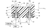
- FIG. 3 is a partial cross-sectional view of the measurement apparatus, and is a cross-sectional view along AA in FIG. 2.
- FIG. 7A is a cross-sectional view taken along the line II of FIG. (FIG.
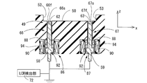
- FIG. 3 is a partial cross-sectional view of the measurement apparatus, and is a BB cross-sectional view of FIG. 2.
- FIG. 3 is a partial cross-sectional view of the measurement apparatus, and is a CC cross-sectional view of FIG. 2.
- FIG. 12A It is a figure which shows the initial state of the recessed part of the said measuring apparatus.
- FIG. 12B FIG.
- FIG. 12 is a view showing a state in which a part is held in a recess in the measuring device.
- FIG. 12C It is a figure which shows the state by which the electrode pair was raised in the said measuring apparatus.
- FIG. 12D It is a figure which shows the state by which the electrode pair was lowered
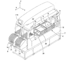
- the mounting machine shown in FIG. 1 mounts a component s on a circuit board P, and includes an apparatus main body 2, a circuit board transport and holding device 4, a component supply device 6, a head moving device 8, and the like.
- the circuit board transport and holding device 4 transports and holds a circuit board P (hereinafter abbreviated as “substrate P”).
- substrate P a circuit board P
- the transport direction of the substrate P is the x direction
- the width direction of the substrate P is y.
- the direction and the thickness direction of the substrate P are defined as the z direction.
- the y direction and the z direction are the front-rear direction and the vertical direction of the mounting machine, respectively. These x direction, y direction, and z direction are orthogonal to each other.
- the component supply device 6 supplies electronic components (hereinafter abbreviated as components) s to be mounted on the board P, and includes a plurality of tape feeders 14 in this embodiment.
- the head moving device 8 holds a mounting head 16 as a work head and moves it in the x, y, and z directions.
- the mounting head 16 has a suction nozzle 18 that sucks and holds the component s.
- Reference numeral 20 denotes a camera.
- the camera 20 images the component s held by the suction nozzle 18 and determines whether the component s is to be mounted on the substrate P based on the image captured by the camera 20. Is done.
- Reference numeral 22 denotes a nozzle station. In the nozzle station 22, a plurality of suction nozzles including an insulation nozzle 24 (see FIGS. 5, 12B, and 12C) that is a suction nozzle formed of an insulating material that is an insulating material are accommodated and replaced as appropriate.
- Reference numeral 26 denotes a measuring apparatus.
- the measuring device 26 measures the electrical characteristics of the component s, and is provided on the main body of the circuit board transporting and holding device 4 via the trash box 28.
- the electrical characteristics of the component s include L (inductance), C (capacitance), R (resistance), Z ′ (impedance), and the like, and one or more of these are measured by the measuring device 26.
- the component s whose electrical characteristics are measured in the measuring device 26 is a square chip having a functional part r provided at an intermediate part and electrodes t provided at both ends. .
- the direction in which the electrodes t are provided at both ends is referred to as the length direction, and the direction orthogonal to the length direction. Is referred to as the width direction.
- the length in the length direction is not necessarily longer than the length in the width direction.
- the component s has a plurality of sizes in which at least one of the length in the length direction and the length in the width direction is different.
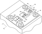
- the measuring device 26 includes a holding base 40 made of an insulating material (for example, resin), and a plurality of recesses 42 opened on the upper surface of the holding base 40. , A plurality of electrode pairs 44 provided corresponding to each of the plurality of recesses 42, a lifting device 46 provided corresponding to each of the plurality of electrode pairs 44, and the like.
- the electrode pair 44 is raised by the lifting device 46, and the anode 48 and the cathode 49 of the electrode pair 44 are applied to the electrodes t at both ends of the component s. By contacting, the electrical characteristics of the part s are measured.
- the recess 42 holds the part as shown in FIG. Further, as shown in FIG. 2, the plurality of recesses 42a to 42i are different in size from each other, and each have a size corresponding to a plurality of sizes of the component s.
- the subscripts a to i are omitted and described when it is not necessary to distinguish each of the recesses 42a to 42i. The same applies to the electrode pair 44, the lifting device 46, and the like.
- the concave portion 42 has a generally rectangular opening and has a bottom surface 50 and two sets of opposing surfaces (52, 53) and (54, 55) facing each other in parallel.
- the recess 42 holds the component s in such a posture that the length direction of the component s is parallel to the opposing surfaces 52 and 53 and the width direction of the component s is parallel to the opposing surfaces 54 and 55.
- the direction of the recess 42 corresponding to the length direction of the component s is referred to as a length direction
- the direction of the recess corresponding to the width direction of the component s is referred to as a width direction.
- the length direction of the recess 42 is the y direction
- the width direction of the recess 42 is the x direction.
- the opposing surfaces 52 to 55 of the concave portion 42 include an inclination suppressing portion that suppresses an inclination of the component s (including at least one of an inclination in a direction parallel to the bottom surface 50 and an inclination in a direction crossing the bottom surface 50) and the displacement of the component s. It is one aspect
- the length m in the length direction and the length n in the width direction of the recess 42 are, for example, a length p in the length direction of the component s and a length q in the width direction, respectively.
- the larger ratio ⁇ and ⁇ can be multiplied.
- the ratios ⁇ and ⁇ can be 1.8 or less, 1.5 or less, 1.4 or less, 1.3 or less, 1.2 or less, 1.1 or less, respectively.
- the gaps between the four facing surfaces 52 to 55 and the component s are determined.
- FIGS. Reference numerals 60 to 63 denote openings of these four holes 56 to 59.
- the openings 60 to 63 are provided in the vicinity of the four corners of the recess 42 so as to be separated from each other.
- two openings 60 to 63 are provided at a position corresponding to the electrode t of the component s, two each in the width direction, in a state where the component s is held in the recess 42.
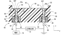
- electrode rods 64 to 67 are arranged so as to be vertically movable.
- the electrode pair 44 includes an anode 48 and a cathode 49.
- the anode 48 includes two electrode bars 64 and 65
- the cathode 49 includes two electrode bars 66 and 67.
- the electrode rods 64 and 65 are connected and connected to the power source 70.
- the cathode 49 two electrode rods 66 and 67 are connected.
- An LCR detector 72 is provided between the anode 48 and the cathode 49. The LCR detector 72 measures the current flowing between the electrodes t at both ends of the component s, and acquires electrical characteristics. In this embodiment, as shown in FIGS. 6 and 9, the cathode 49 is grounded.
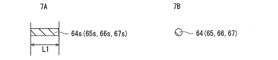
- the cross section of the intermediate portion is generally circular, but as shown in FIG. 7A, the cross sections of the tip portions 64s to 67s are long in the length direction of the recess 42. It is generally rectangular. As shown in FIGS. 3, 4, and 12C, the length L1 of the tip portions 64s to 67s in the length direction is longer than the length L2 of the corresponding electrode portion t of the component s.
- the elevating device 46 is of an electromagnetic solenoid type and includes solenoids 84 to 87 provided corresponding to the electrode rods 64 to 67 as shown in FIGS.
- the solenoids 84 to 87 have the same structure, and each include a lifting device main body 88, a coil 90, a drive shaft 92, a spring 94, and the like.
- the spring 94 is provided between the drive shaft 92 and the lifting device main body 88 (fixed portion), and urges the drive shaft 92 downward.
- the electrode rods 64 to 67 are respectively connected to the drive shaft 92 and can be moved integrally. In other words, it can be considered that the drive shaft 92 is a part of the electrode rods 64 to 67.
- the drive shaft 92 and the electrode rods 64 to 67 are in the lower end positions, and as shown in FIGS. 6, 8, 9, and 12A, the tip portions 64s to 67s.
- the contact surfaces 64f to 67f that are the upper surfaces of the openings are located below the edges of the openings 60 to 63, that is, the bottom surface 50.
- the mounting machine includes a control device 100.
- the control device 100 includes a controller 102 mainly composed of a computer and a plurality of drive circuits 104.
- the controller 102 includes an execution unit 110, a storage unit 112, an input / output unit 114, and the like.
- the substrate transfer holding device 4, the component supply device 6, and the head moving device 8 each include a drive circuit 104.
- a plurality of coils 90 and the like are connected.
- the LCR detection unit 72, the display 116, and the like are connected.
- the storage unit 112 stores a plurality of programs and tables such as the LCR measurement program represented by the flowchart of FIG. The time is measured by a timer 124 provided in the controller 102.
- the operation of the mounting machine will be described.
- a command for measuring the electrical characteristics of the part s is issued, such as when a new tape feeder 14 is set or the tape feeder 14 is replaced, the electrical of the part s held by the tape feeder 14 is output. Characteristics are measured.
- the measured value which is the value of the measured electrical characteristic, is compared with the standard value of the part s, and it is determined whether or not these values substantially match.
- the component s is used for mounting on the board P, and is determined to be inappropriate.
- the part s is discarded into the trash box 28.
- the result of comparing the measured value with the standard value is displayed on the display 116.
- the electrical characteristics of the component s are measured by executing the LCR measurement program represented by the flowchart of FIG.
- the measuring device 26 is in the initial state shown in FIG. 12A.
- the electrode rods 64 to 67 are at the lower end position, and the contact surfaces 64f to 67f are respectively positioned below the bottom surface 50.
- step 1 it is determined whether or not a measurement command for the electrical characteristics of the component s has been issued.
- the mounting head 16 is moved to the nozzle station 22 and the insulating nozzle 24 is attached in S2.
- the mounting head 16 is moved to the component supply device 6, and for example, the component s held by the newly attached tape feeder 14 is picked up by the insulating nozzle 24.
- the mounting head 16 is moved to the measuring device 26, and as shown in FIG. 12B, the component s is placed on the bottom surface 50 of the recess 42 corresponding to the size of the component s and held from below. Further, the component s is held by the insulating nozzle 24 from above.
- the electrode rods 64 to 67 are raised. As shown in FIG. 12C, the contact surfaces 64f to 67f are slightly above the bottom surface 50 and contact the electrode t of the component s. Since the length L1 in the length direction of each contact surface 64f to 67f of the electrode rods 64 to 67 is longer than the length L2 in the length direction of the electrode portion t of the component s, the electrode rod 64 is connected to the electrode portion t of the component s. The contact surfaces 64f to 67f can be satisfactorily brought into contact with each other. The electrode rods 64 to 67 are raised while the component s is held by the insulating nozzle 24 from above. However, since the insulating nozzle 24 has a spring (not shown), even if the component s slightly rises, Displacement is allowed.
- the static elimination time is the time required to remove the static electricity of the capacity estimated to be possessed by the part s, and is obtained in advance by experiments or theoretically based on the size, characteristics, etc. of the part s. You can do it.
- the holding table 40 is made of an insulating material, even if the component s comes into contact with the bottom surface 50, the charge removal is not performed.
- the suction port of the insulating nozzle 24 may be larger than the functional part r of the component s, and the component s is held well by the insulating nozzle 24. May not be possible. In that case, the component s may be inclined or shifted in parallel with the bottom surface 50 or intersecting the bottom surface 50.
- the component s is surrounded by the facing surfaces 52 to 55. By these facing surfaces 52 to 55, the inclination and deviation of the component s are satisfactorily suppressed.
- the anode 48 and the cathode 49 include two electrode rods 64 and 65 and electrode rods 66 and 67, respectively, at least one of the contact surfaces 64f and 65f of the electrode rods 64 and 65; If at least one contact surface 66f, 67f of the two electrode rods 66, 67 constituting the cathode 49 is in contact with the electrode part t of the component s, it is possible to measure the electrical characteristics of the component s. .
- the electrode pair 44 is lowered and separated from the part s in S6.
- S7 it is determined whether or not the measured value that is the measured electrical characteristic substantially matches the standard value of the component s. If they substantially match, as shown in FIG. 12D, in S8, the mounting head 16 is moved to the substrate P with the component s held by the insulating nozzle 24, and the component s is mounted. If the measured value and the standard value do not match, the part s is discarded into the trash box 28 in S9. When the measured value and the standard value are almost the same, the part s is appropriate, and therefore the necessity for discarding the part s is low. Further, although the insulating nozzle 24 is used, the charge of the component s is small because the charge removal is performed using the cathode 49. Therefore, the component s can be used for mounting on the board P.
- the execution of S2 corresponds to the holding process
- the execution of S3 corresponds to the electrode pair raising process
- the execution of S4 corresponds to the static elimination process
- the execution of S5 corresponds to the measurement process
- the execution of S6 corresponds to the electrode pair lowering process.
- Execution of S7 corresponds to the suitability determination process
- execution of S8 corresponds to the mounting process.
- the head movement control device is configured by a portion that stores S2 and S8 of the LCR measurement program represented by the flowchart of FIG.
- the tilt limiting portion is constituted by the two sets of facing surfaces 52 to 55 of the recess 42.
- the concave portion 42 corresponds to the component holding portion
- the bottom surface 50 is a holding surface.
- step S4 is not indispensable. If the static elimination time is very short, it can be ignored.
- the measuring table 40 is made of an insulating material, it can be made of a material having antistatic properties.
- the shape of the tip portion of the electrode rods 64 to 67 is not limited. Any shape that can contact the electrode t of the component s may be used.
- the present disclosure may include a wall portion that protrudes upward from the upper surface. It can be implemented in a form in which various changes and improvements are made based on the knowledge of the trader.
- Measuring device 40 Measuring table 42: Recess 44: Electrode pair 46: Lifting device 48: Anode 49: Cathode 50: Bottom surface 60-63: Opening 64-67: Electrode rod 70: Power supply 72: LCR detector 84-87 : Solenoid 90: Coil 100: Control device
- a mounting machine that picks up a component supplied by a component supply device and mounts it on a circuit board;
- a holding stand having a component holding portion capable of holding the component;
- An electrode pair including an anode and a cathode, in contact with the component held on a holding surface of the component holding unit, and measuring an electrical characteristic of the component;
- a measuring apparatus including an elevating device for bringing the anode and the cathode into contact with the component by raising the anode and the cathode upward from the holding surface.
- the anode and the cathode are not moved closer to or away from each other, but both the anode and the cathode are raised, and the parts are moved closer and lowered. Separated from Further, the anode and the cathode come above the holding surface on which the component is held, thereby contacting the component and measuring the electrical characteristics.
- the component holding unit includes an inclination suppressing unit that suppresses an inclination of the component.
- the inclination suppressing unit suppresses the inclination of the component, but can also suppress the movement (displacement) of the component.
- the inclination suppression unit includes at least a pair of opposing surfaces provided on the holding table and parallel to each other. It is not always necessary to provide two pairs of facing surfaces. When a direction in which a component is easily tilted is determined in advance, only a pair of facing surfaces capable of suppressing the tilt in that direction may be provided. At least a pair of opposed surfaces are provided so as to protrude upward from the holding surface. Even if the holding surface is the upper surface of the holding table, the holding surface is a surface positioned below the upper surface of the holding table (for example, the bottom surface of the recess). May be possible).
- the component holding portion is a recess formed in the holding base and opening upward, and the bottom surface of the recess is the holding surface.
- a plurality of the recesses are formed on the holding table, The measuring apparatus according to item (5), wherein the plurality of recesses have different sizes.
- each of the recesses has a size corresponding to a size of a component.
- (9) provided in a mounting machine that picks up a component supplied by a component supply device and mounts the component on a circuit board;
- a holding table having a plurality of component holding units capable of holding the components;
- a measuring device that is provided corresponding to each of the plurality of component holding units and includes a plurality of electrode pairs that measure electrical characteristics of the component;
- the measuring apparatus in which the plurality of component holding portions are a plurality of concave portions having different sizes and opening upward provided on the holding base.
- a holding table having a plurality of component holding units capable of holding the components;
- a measuring device that is provided corresponding to each of the plurality of component holding units and includes a plurality of electrode pairs that measure electrical characteristics of the component;
- the component holding part is made of an insulating material,
- a measuring apparatus in which at least one of an anode and a cathode constituting the electrode pair is grounded.
- a measurement method for measuring electrical characteristics of a component held on a holding surface of a component holding unit An electrode pair raising step for bringing the electrode pair into contact with the component by raising the electrode pair above the holding surface; A measuring step of measuring the electrical characteristics of the component while the electrode pair is in contact with the component; A measurement method including a step of lowering the electrode pair from the component by lowering the electrode pair downward from the holding surface.
- At least one of the anode and the cathode constituting the electrode pair is in a grounded state,
- the component is moved to a predetermined position on the circuit board after the electrode pair lowering step.
- a mounting machine that picks up a component supplied by a component supply device and mounts the component on a circuit board, A measuring device for measuring the electrical characteristics of the component using an electrode pair;
- a work head having an insulating nozzle that is an adsorption nozzle formed of an insulating material capable of adsorbing and holding the component;
- a head moving device for moving the working head;
- a head movement control device that controls the movement of the working head by controlling the head movement device, At least one of an anode and a cathode constituting the electrode pair is grounded;
- the mounting machine in which the head movement control device moves the insulating nozzle among the component supply device, the measurement device, and the circuit board.
Landscapes
- Engineering & Computer Science (AREA)
- Physics & Mathematics (AREA)
- General Physics & Mathematics (AREA)
- Operations Research (AREA)
- Manufacturing & Machinery (AREA)
- Microelectronics & Electronic Packaging (AREA)
- Supply And Installment Of Electrical Components (AREA)
- Testing Electric Properties And Detecting Electric Faults (AREA)
Abstract
測定装置において、仮に、部品が小さくても、電気的特性を良好に測定可能とすることである。 本測定装置は、部品を保持する部品保持部と、電極対と、電極対を昇降させる昇降装置とを含む。本測定装置においては、部品保持部に保持された部品に、電極対が上昇させられることにより、接触させられ、電気的特性が測定される。このように、電気的特性が、部品が部品保持部に保持された状態で測定されるため、部品が小さくても、良好に電気的特性の測定を行うことができる。
Description
本開示は、回路基板に装着される部品の電気的特性の測定を行う測定装置、部品の電気的特性の測定方法に関するものである。
特許文献1には、測定台と、測定台の上面から突出して設けられた電極対とを含む測定装置が記載されている。特許文献1に記載の測定装置においては、絶縁性を有する材料で製造された吸着ノズルである絶縁ノズルにより部品が保持され、電極対の上に載せられて、部品の電気的特性が測定される。
本開示の課題は、仮に、部品が小さい場合であっても、電気的特性を良好に測定可能とすることである。
本開示に係る測定装置は、部品を保持する部品保持部と、電極対と、電極対を昇降させる昇降装置とを含む。本測定装置においては、部品保持部に保持された部品に、電極対が上昇させられることにより、接触し、電気的特性が測定される。このように、電気的特性が、部品が部品保持部に保持された状態で測定されるため、部品が小さくても、良好に電気的特性の測定を行うことができる。
以下、本開示の一実施形態である測定装置を含む装着機について図面に基づいて詳細に説明する。本測定装置においては、本開示の一実施形態である測定方法が実施される。
図1に示す装着機は、部品sを回路基板Pに装着するものであり、装置本体2,回路基板搬送保持装置4,部品供給装置6,ヘッド移動装置8等を含む。
回路基板搬送保持装置4は、回路基板P(以下、基板Pと略称する)を搬送して保持するものであり、図1において、基板Pの搬送方向をx方向、基板Pの幅方向をy方向、基板Pの厚み方向をz方向とする。y方向、z方向は、それぞれ、装着機の前後方向、上下方向である。これら、x方向、y方向、z方向は互いに直交する。部品供給装置6は、基板Pに装着される電子部品(以下、部品と略称する)sを供給するものであり、本実施例においては、複数のテープフィーダ14を含む。ヘッド移動装置8は、作業ヘッドとしての装着ヘッド16を保持してx、y、z方向へ移動させるものであり、装着ヘッド16は、部品sを吸着して保持する吸着ノズル18を有する。
図1に示す装着機は、部品sを回路基板Pに装着するものであり、装置本体2,回路基板搬送保持装置4,部品供給装置6,ヘッド移動装置8等を含む。
回路基板搬送保持装置4は、回路基板P(以下、基板Pと略称する)を搬送して保持するものであり、図1において、基板Pの搬送方向をx方向、基板Pの幅方向をy方向、基板Pの厚み方向をz方向とする。y方向、z方向は、それぞれ、装着機の前後方向、上下方向である。これら、x方向、y方向、z方向は互いに直交する。部品供給装置6は、基板Pに装着される電子部品(以下、部品と略称する)sを供給するものであり、本実施例においては、複数のテープフィーダ14を含む。ヘッド移動装置8は、作業ヘッドとしての装着ヘッド16を保持してx、y、z方向へ移動させるものであり、装着ヘッド16は、部品sを吸着して保持する吸着ノズル18を有する。
また、符号20はカメラを示す。カメラ20は、吸着ノズル18によって保持された部品sを撮像するものであり、カメラ20によって撮像された画像に基づいて、部品sが基板Pに装着される予定のものであるか否かが判定される。符号22は、ノズルステーションを示す。ノズルステーション22には、絶縁性を有する材料である絶縁材で形成された吸着ノズルである絶縁ノズル24(図5,12B,12C参照)を含む複数の吸着ノズルが収容され、適宜交換される。
符号26は測定装置を示す。測定装置26は、部品sの電気的特性を測定するものであり、ごみ箱28を介して回路基板搬送保持装置4の本体に設けられる。部品sの電気的特性としては、L(インダクタンス)、C(キャパシタンス)、R(レジスタンス)、Z′(インピーダンス)等が該当し、測定装置26によってこれらのうちの1つ以上が測定される。
本測定装置26において電気的特性が測定される部品sは、図3等に示すように、中間部に設けられた機能部rと、両端部に設けられた電極tとを有する角チップである。以下、本実施例において、部品sにおいて、両端部に電極tが設けられた方向(電極t、機能部r、電極tが並んだ方向)を長さ方向と称し、長さ方向と直交する方向を幅方向と称する。ただし、長さ方向の長さが幅方向の長さより長いとは限らない。また、部品sについては、長さ方向の長さと幅方向の長さとの少なくとも一方が異なる複数のサイズのものがある。
本測定装置26において電気的特性が測定される部品sは、図3等に示すように、中間部に設けられた機能部rと、両端部に設けられた電極tとを有する角チップである。以下、本実施例において、部品sにおいて、両端部に電極tが設けられた方向(電極t、機能部r、電極tが並んだ方向)を長さ方向と称し、長さ方向と直交する方向を幅方向と称する。ただし、長さ方向の長さが幅方向の長さより長いとは限らない。また、部品sについては、長さ方向の長さと幅方向の長さとの少なくとも一方が異なる複数のサイズのものがある。
測定装置26は、図2,4,6~9に示すように、絶縁材(例えば、樹脂とすることができる)で製造された保持台40、保持台40の上面に開口する複数の凹部42、複数の凹部42の各々に対応して設けられた複数の電極対44、複数の電極対44の各々に対応して設けられた昇降装置46等を含む。本測定装置26において、部品sが凹部42に保持された状態において、電極対44が昇降装置46によって上昇させられ、その電極対44の陽極48、陰極49が部品sの両端部の電極tに接触することにより、部品sの電気的特性が測定される。
凹部42は、図3に示すように部品を保持するものである。また、図2に示すように、複数の凹部42a~iは、互いに大きさが異なるものであり、それぞれ、部品sの複数のサイズに対応した大きさのものとされる。以下、凹部42a~iについて、構造は同じであるため、凹部42a~iの各々を区別する必要がない場合には、添え字a~iを省略して記載する。電極対44、昇降装置46等についても同様である。
凹部42は、概して四角形の開口を有するものであり、底面50と、2組の互いに平行に対向する対向面(52,53)、(54,55)とを有する。凹部42には、原則として、部品sの長さ方向が対向面52,53と平行な方向、部品sの幅方向が対向面54,55と平行な方向となる姿勢で、部品sが保持される。以下、凹部42に部品sが保持された状態において、部品sの長さ方向に対応する凹部42の方向を長さ方向、部品sの幅方向に対応する凹部の方向を幅方向と称する。本実施例において、凹部42の長さ方向がy方向であり、凹部42の幅方向がx方向である。凹部42の対向面52~55は、部品sの傾き(底面50と平行な向きの傾きと底面50と交差する向きの傾きとの少なくとも一方を含む)、部品sのずれを抑制する傾斜抑制部の一態様である。
図3に示すように、凹部42の長さ方向の長さm、幅方向の長さnは、それぞれ、例えば、部品sの長さ方向の長さp、幅方向の長さqに、1より大きい比率β、γを掛けた大きさとすることができる。
m=p・β
n=q・γ
比率β、γは、それぞれ、1.8以下、1.5以下、1.4以下、1.3以下、1.2以下、1.1以下等とすることができる。
対向面52~55と部品sとの隙間が小さい場合には部品sの傾きやずれの許容量が小さくなり、隙間が大きい場合には部品sの傾きや移動の許容量が大きくなる。一方、対向面52~55と部品sとの隙間を小さくするためには、凹部42の加工に高い精度が要求され、加工コストが高くなる。以上の事情に基づいて、4つの対向面52~55と部品sとの隙間が決まる。
m=p・β
n=q・γ
比率β、γは、それぞれ、1.8以下、1.5以下、1.4以下、1.3以下、1.2以下、1.1以下等とすることができる。
対向面52~55と部品sとの隙間が小さい場合には部品sの傾きやずれの許容量が小さくなり、隙間が大きい場合には部品sの傾きや移動の許容量が大きくなる。一方、対向面52~55と部品sとの隙間を小さくするためには、凹部42の加工に高い精度が要求され、加工コストが高くなる。以上の事情に基づいて、4つの対向面52~55と部品sとの隙間が決まる。
また、測定台40の底面50の下方には、図6,8,9に示すように、それぞれ上下方向に伸びた4つの穴56~59が形成される。符号60~63は、これら4つの穴56~59の開口を示す。開口60~63は、互いに隔たって、凹部42の4つのコーナ付近に設けられる。換言すれば、開口60~63は、凹部42に部品sが保持された状態において、部品sの電極tに対応する位置に、それぞれ2つずつ、幅方向に隔たって設けられる。そして、4つの穴56~59の各々には、それぞれ、電極棒64~67が上下方向に昇降可能に配設される。
電極対44は、陽極48と陰極49とを含む。図8に示すように、陽極48は2つの電極棒64,65を含み、図9に示すように、陰極49は2つの電極棒66,67を含む。陽極48において、電極棒64,65が連結されるとともに、電源70に接続される。陰極49において、2つの電極棒66,67が連結される。また、陽極48と陰極49との間には、LCR検出部72が設けられる。LCR検出部72によって、部品sの両端部の電極tの間に流れた電流が測定され、電気的特性が取得される。なお、本実施例においては、図6,9に示すように、陰極49が接地(アース)される。
電極棒64~67の各々において、図7Bに示すように、中間部の断面は概して円形を成すが、図7Aに示すように、先端部64s~67sの断面は凹部42の長さ方向に長い概して長方形を成す。図3,4,12Cに示すように、先端部64s~67sの長さ方向の長さL1は、それに対応する部品sの電極部tの長さ方向の長さL2より長い。
昇降装置46は、電磁ソレノイド式のものであり、図6,8,9に示すように、電極棒64~67の各々に対応して設けられたソレノイド84~87を含む。ソレノイド84~87は、同じ構造を成すものであり、それぞれ、昇降装置本体88と、コイル90と、駆動軸92と、スプリング94等を含む。スプリング94は、駆動軸92と昇降装置本体88(固定部)との間に設けられ、駆動軸92を下方に付勢する。電極棒64~67は、それぞれ、駆動軸92に連結され、一体的に移動可能とされる。換言すれば、駆動軸92は電極棒64~67の一部であると考えることもできる。
ソレノイド84~87の各々において、コイル90に電流が供給されない間、駆動軸92および電極棒64~67は下端位置にあり、図6,8,9、12Aに示すように、先端部64s~67sの上面である接触面64f~67fは、上記開口60~63の縁、すなわち、底面50より下方に位置する。コイル90に電流が供給されると、駆動軸92は、スプリング84の付勢力に抗して上昇させられ、電極棒64~67の接触面64f~67fは、底面50よりわずか上に至る。
ソレノイド84~87の各々において、コイル90に電流が供給されない間、駆動軸92および電極棒64~67は下端位置にあり、図6,8,9、12Aに示すように、先端部64s~67sの上面である接触面64f~67fは、上記開口60~63の縁、すなわち、底面50より下方に位置する。コイル90に電流が供給されると、駆動軸92は、スプリング84の付勢力に抗して上昇させられ、電極棒64~67の接触面64f~67fは、底面50よりわずか上に至る。
当該装着機は制御装置100を含む。制御装置100は、図10に示すように、コンピュータを主体とするコントローラ102と、複数の駆動回路104とを含む。コントローラ102は、実行部110、記憶部112、入出力部114等を含み、入出力部114には、基板搬送保持装置4、部品供給装置6、ヘッド移動装置8が、それぞれ、駆動回路104を介して接続されるとともに、複数のコイル90等が接続される。また、LCR検出部72、ディスプレイ116等が接続される。記憶部112には、図11のフローチャートで表されるLCR測定プログラム等の複数のプログラム、テーブルが記憶されている。また、コントローラ102に設けられたタイマ124によって時間が計測される。
以下、装着機の作動について説明する。
新たなテープフィーダ14のセット、テープフィーダ14の交換等が行われた場合等、部品sの電気的特性の測定指令が出された場合に、そのテープフィーダ14に保持された部品sの電気的特性が測定される。また、測定された電気的特性の値である測定値と、その部品sの規格値とが比較され、これらがほぼ一致するか否かが判定される。測定値と規格値とがほぼ一致し、測定値が適正な値であると判定された場合には、その部品sが基板Pへの装着に使用され、不適正であると判定された場合には、その部品sはごみ箱28へ廃棄される。また、測定値と規格値とを比較した結果は、ディスプレイ116に表示される。
新たなテープフィーダ14のセット、テープフィーダ14の交換等が行われた場合等、部品sの電気的特性の測定指令が出された場合に、そのテープフィーダ14に保持された部品sの電気的特性が測定される。また、測定された電気的特性の値である測定値と、その部品sの規格値とが比較され、これらがほぼ一致するか否かが判定される。測定値と規格値とがほぼ一致し、測定値が適正な値であると判定された場合には、その部品sが基板Pへの装着に使用され、不適正であると判定された場合には、その部品sはごみ箱28へ廃棄される。また、測定値と規格値とを比較した結果は、ディスプレイ116に表示される。
部品sの電気的特性は、図11のフローチャートで表されるLCR測定プログラムの実行により測定される。
装着機の非作動状態において、測定装置26は、図12Aに示す初期状態にある。電極棒64~67は下端位置にあり、接触面64f~67fは、それぞれ、底面50より下方に位置する。
装着機の非作動状態において、測定装置26は、図12Aに示す初期状態にある。電極棒64~67は下端位置にあり、接触面64f~67fは、それぞれ、底面50より下方に位置する。
ステップ1(以下、S1と略称する。他のステップについても同様とする)において、部品sの電気的特性の測定指令が出されたか否かが判定される。測定指令が出された場合には、S2において、装着ヘッド16がノズルステーション22へ移動させられ、絶縁ノズル24が取り付けられる。次に、装着ヘッド16が部品供給装置6へ移動させられ、例えば、新たに取り付けられたテープフィーダ14に保持された部品sが絶縁ノズル24によってピックアップされる。そして、装着ヘッド16が測定装置26へ移動させられ、図12Bに示すように、部品sが、その部品sのサイズに対応する凹部42の底面50へ載せられて、下から保持される。また、部品sは、上から絶縁ノズル24によって保持されたままである。
S3において、電極棒64~67が上昇させられる。図12Cに示すように、接触面64f~67fは、底面50よりわずか上に至り、部品sの電極tに接触する。電極棒64~67の各々の接触面64f~67fの長さ方向の長さL1は部品sの電極部tの長さ方向の長さL2より長いため、部品sの電極部tに電極棒64~67の接触面64f~67fを良好に接触させることができる。なお、部品sは絶縁ノズル24によって上から保持された状態で、電極棒64~67が上昇させられるが、絶縁ノズル24が図示しないスプリングを有するため、部品sがわずかに上昇しても、その変位が許容される。
S4において、電極対44が上昇させられた時点(陰極49の接触面66f、67fの少なくとも一方が部品sの電極tに接触した時点)から除電時間が経過するのが待たれる。除電時間は、部品sが有していると推定される容量の静電気を除去するのに要する時間であり、予め実験等により求めたり、部品sの大きさ、特性等に基づいて理論的に求めたりすること等ができる。一方、本実施例において、保持台40は絶縁材で形成されたものであるため、部品sが底面50に当接しても除電が行われることはない。また、部品sは絶縁ノズル24によって保持されるため、絶縁ノズル24を介して除電が行われることもない。それに対して、陰極49がアースされているため、部品sに蓄えられた電荷は陰極49を介して逃がされ、除電が行われるのである。
そして、経過時間が除電時間に達した後に、S5において、陽極48、陰極49の間に電圧が印加されて、LCR検出部72によって電流が測定されて、部品sの電気的特性が求められる。陽極48と陰極49との間に印加された電圧、流れる電流等に基づき、L,C,R等が求められるのである。
そして、経過時間が除電時間に達した後に、S5において、陽極48、陰極49の間に電圧が印加されて、LCR検出部72によって電流が測定されて、部品sの電気的特性が求められる。陽極48と陰極49との間に印加された電圧、流れる電流等に基づき、L,C,R等が求められるのである。
一方、部品sが小さい場合には、図5に示すように、部品sの機能部rより絶縁ノズル24の吸着口の方が大きい場合もあり、絶縁ノズル24によって部品sを良好に保持することができない場合がある。その場合には、部品sが底面50と平行にまたは底面50に対して交差して傾いたり、ずれたりする場合がある。それに対して、本測定装置26においては、部品sが対向面52~55によって囲まれる。これら対向面52~55によって、部品sの傾きやずれが良好に抑制されるのである。
また、部品sが傾いたり、ずれたりすることにより、4つの電極棒64~67の接触面64f~67fのすべてが部品sの電極部tに接触しない場合がある。それに対して、陽極48、陰極49が、それぞれ、2つずつの電極棒64,65、電極棒66,67を含むため、電極棒64,65のうちの少なくとも一方の接触面64f、65fと、陰極49を構成する2つの電極棒66,67のうちの少なくとも一方の接触面66f、67fとが部品sの電極部tに接触すれば、部品sの電気的特性を測定することが可能となる。
また、部品sが傾いたり、ずれたりすることにより、4つの電極棒64~67の接触面64f~67fのすべてが部品sの電極部tに接触しない場合がある。それに対して、陽極48、陰極49が、それぞれ、2つずつの電極棒64,65、電極棒66,67を含むため、電極棒64,65のうちの少なくとも一方の接触面64f、65fと、陰極49を構成する2つの電極棒66,67のうちの少なくとも一方の接触面66f、67fとが部品sの電極部tに接触すれば、部品sの電気的特性を測定することが可能となる。
部品sの電気的特性の測定後、S6において、電極対44が下降させられ、部品sから離間させられる。S7において、測定された電気的特性である測定値がその部品sの規格値とほぼ一致するか否かが判定される。ほぼ一致する場合には、図12Dに示すように、S8において、装着ヘッド16は、部品sが絶縁ノズル24によって保持された状態で、基板Pへ移動させられ、部品sが装着される。測定値と規格値とが不一致である場合には、S9において、部品sはごみ箱28へ廃棄させられる。測定値と規格値とがほぼ一致する場合には、その部品sは適正なものであるため、その部品sを廃棄する必要性は低い。また、絶縁ノズル24が利用されるが、陰極49を利用して除電が行われるため、部品sの帯電量が少ない。そのため、部品sは、基板Pへの装着に使用することができるのである。
以上のように、本実施例においては、仮に、部品sが小さい場合であっても、安定した姿勢で、良好に電気的特性を測定することが可能となる。なお、部品sが大きい場合であっても、電気的特性を自動で測定することが可能である。
本実施例においては、S2の実行が保持工程、S3の実行が電極対上昇工程、S4の実行が除電工程、S5の実行が測定工程に対応し、S6の実行が電極対下降工程に対応する。S7の実行が適否判定工程、S8の実行が装着工程に対応する。また、制御装置100の図11のフローチャートで表されるLCR測定プログラムのS2,8を記憶する部分、実行する部分等によりヘッド移動制御装置が構成される。また、凹部42の2組の対向面52~55等により傾斜制限部が構成される。さらに、凹部42が部品保持部に対応し、底面50が保持面とされる。
なお、S4のステップは不可欠ではない。除電時間が非常に短い場合には、無視することも可能である。
また、測定台40は、絶縁材で形成されたものであるが、帯電防止性を有する材料で形成されるようにすることもできる。
さらに、陽極48、陰極49の各々を構成する電極棒64,65、電極棒66,67を2本ずつ設けることは不可欠ではなく、1本ずつまたは2本以上ずつでもよい。また、電極棒64~67の先端部の形状は問わない。部品sの電極tに接触可能な形状であればよい。
さらに、測定台40の上面に開口する凹部42を設けることは不可欠ではなく、上面から上方へ突出する壁部を設けてもよい等、本開示は、前記実施形態に記載の態様の他、当業者の知識に基づいて種々の変更、改良を施した形態で実施することができる。
26:測定装置 40:測定台 42:凹部 44:電極対 46:昇降装置 48:陽極 49:陰極 50:底面 60~63:開口 64~67:電極棒 70:電源 72:LCR検出部 84~87:ソレノイド 90:コイル 100:制御装置
以下の各項に、特許請求可能な態様を記載する。
(1)部品供給装置によって供給された部品をピックアップして回路基板に装着する装着機に設けられ、
前記部品を保持可能な部品保持部を備えた保持台と、
陽極と陰極とを含み、前記部品保持部の保持面に保持された前記部品に接触して、前記部品の電気的特性を測定する電極対と、
前記陽極と前記陰極とを、前記保持面より上方へ上昇させることにより前記部品に接触させる昇降装置と
を含む測定装置。
本項に記載の測定装置においては、陽極と陰極とが、互いに接近・離間するのではなく、陽極と陰極との両方が上昇させられることにより、部品に接近し、下降させられることにより、部品から離間させられる。また、陽極と陰極とが、部品が保持された保持面より上方に至ることにより部品に接触し、電気的特性が測定される。
(1)部品供給装置によって供給された部品をピックアップして回路基板に装着する装着機に設けられ、
前記部品を保持可能な部品保持部を備えた保持台と、
陽極と陰極とを含み、前記部品保持部の保持面に保持された前記部品に接触して、前記部品の電気的特性を測定する電極対と、
前記陽極と前記陰極とを、前記保持面より上方へ上昇させることにより前記部品に接触させる昇降装置と
を含む測定装置。
本項に記載の測定装置においては、陽極と陰極とが、互いに接近・離間するのではなく、陽極と陰極との両方が上昇させられることにより、部品に接近し、下降させられることにより、部品から離間させられる。また、陽極と陰極とが、部品が保持された保持面より上方に至ることにより部品に接触し、電気的特性が測定される。
(2)前記陽極と前記陰極との少なくとも一方が接地された(1)項に記載の測定装置。
陽極と陰極とのいずれか一方が接地されるようにしても両方が接地されるようにしてもよい。
陽極と陰極とのいずれか一方が接地されるようにしても両方が接地されるようにしてもよい。
(3)前記部品保持部が、前記部品の傾きを抑制する傾斜抑制部を含む(1)項または(2)項に記載の測定装置。
傾斜抑制部は、部品の傾きを抑制するが、部品の移動(ずれ)も抑制することができる。
傾斜抑制部は、部品の傾きを抑制するが、部品の移動(ずれ)も抑制することができる。
(4)前記傾斜抑制部が、前記保持台に設けられ、互いに平行な少なくとも一対の対向面を含む(3)項に記載の測定装置。
対向面を2対設ける必要は必ずしもなく、部品について予め傾き易い方向が決まっている場合には、その方向の傾きを抑制可能な一対の対向面を設けるのみでもよい。少なくとも一対の対向面は、保持面から上方へ突出して設けられるが、保持面は、保持台の上面であっても、保持台の上面より下方に位置する面(例えば、凹部の底面とすることができる)であってもよい。
対向面を2対設ける必要は必ずしもなく、部品について予め傾き易い方向が決まっている場合には、その方向の傾きを抑制可能な一対の対向面を設けるのみでもよい。少なくとも一対の対向面は、保持面から上方へ突出して設けられるが、保持面は、保持台の上面であっても、保持台の上面より下方に位置する面(例えば、凹部の底面とすることができる)であってもよい。
(5)前記部品保持部が、前記保持台に形成された上方に開口する凹部とされ、前記凹部の底面が前記保持面とされた(1)項ないし(4)項のいずれか1つに記載の測定装置。
(6)前記凹部が、前記保持台に複数形成され、
前記複数の凹部が、互いに大きさが異なるものとされた(5)項に記載の測定装置。
前記複数の凹部が、互いに大きさが異なるものとされた(5)項に記載の測定装置。
(7)前記凹部の各々は、それぞれ、部品のサイズに対応する大きさとされた(6)旨に記載の測定装置。
(8)前記部品保持部が、絶縁性を有する材料で製造された(1)項ないし(7)項のいずれか1つに記載の測定装置。
(9)部品供給装置によって供給された部品をピックアップして回路基板に装着する装着機に設けられ、
前記部品を保持可能な複数の部品保持部を備えた保持台と、
前記複数の部品保持部の各々に対応して設けられ、前記部品の電気的特性を測定する複数の電極対と
を含む測定装置であって、
前記複数の部品保持部が、前記保持台に設けられた上方に開口する互いに大きさが異なる複数の凹部とされた測定装置。
本項に記載の測定装置には、(1)項ないし(8)項の各々に記載の技術的特徴を採用することができる。
前記部品を保持可能な複数の部品保持部を備えた保持台と、
前記複数の部品保持部の各々に対応して設けられ、前記部品の電気的特性を測定する複数の電極対と
を含む測定装置であって、
前記複数の部品保持部が、前記保持台に設けられた上方に開口する互いに大きさが異なる複数の凹部とされた測定装置。
本項に記載の測定装置には、(1)項ないし(8)項の各々に記載の技術的特徴を採用することができる。
(10)部品供給装置によって供給された部品をピックアップして回路基板に装着する装着機に設けられ、
前記部品を保持可能な複数の部品保持部を備えた保持台と、
前記複数の部品保持部の各々に対応して設けられ、前記部品の電気的特性を測定する複数の電極対と
を含む測定装置であって、
前記部品保持部が、絶縁性を有する材料で製造されたものであり、
前記電極対を構成する陽極と陰極との少なくとも一方が接地された測定装置。
本項に記載の測定装置には、(1)項ないし(8)項の各々に記載の技術的特徴を採用することができる。
前記部品を保持可能な複数の部品保持部を備えた保持台と、
前記複数の部品保持部の各々に対応して設けられ、前記部品の電気的特性を測定する複数の電極対と
を含む測定装置であって、
前記部品保持部が、絶縁性を有する材料で製造されたものであり、
前記電極対を構成する陽極と陰極との少なくとも一方が接地された測定装置。
本項に記載の測定装置には、(1)項ないし(8)項の各々に記載の技術的特徴を採用することができる。
(11)部品保持部の保持面に保持された部品の電気的特性を測定する測定方法であって、
電極対を前記保持面より上方へ上昇させることにより前記部品に接触させる電極対上昇工程と、
前記電極対が前記部品に接触した状態で、前記部品の電気的特性を測定する測定工程と、
前記電極対を前記保持面より下方へ下降させることにより前記部品から離間させる電極対下降工程と
を含む測定方法。
電極対を前記保持面より上方へ上昇させることにより前記部品に接触させる電極対上昇工程と、
前記電極対が前記部品に接触した状態で、前記部品の電気的特性を測定する測定工程と、
前記電極対を前記保持面より下方へ下降させることにより前記部品から離間させる電極対下降工程と
を含む測定方法。
(12)前記電極対を構成する陽極と陰極との少なくとも一方が接地された状態にあり、
前記電極対上昇工程の後、前記測定工程の前に、前記部品に前記陽極と前記陰極とが接触した状態で、前記部品の除電を行う除電工程を設けた(11)項に記載の測定方法。
前記電極対上昇工程の後、前記測定工程の前に、前記部品に前記陽極と前記陰極とが接触した状態で、前記部品の除電を行う除電工程を設けた(11)項に記載の測定方法。
(13)前記測定工程において測定された前記部品の電気的特性が適正な値である場合には、前記電極対下降工程の後に、前記部品を、回路基板上の予め定められた位置へ運んで、装着させる装着工程を設けた(11)項または(12)項に記載の測定方法。
(14)部品供給装置によって供給された部品をピックアップして回路基板に装着する装着機であって、
前記部品の電気的特性を電極対を利用して測定する測定装置と、
前記部品を吸着して保持可能であって、絶縁性を有する材料で形成された吸着ノズルである絶縁ノズルを有する作業ヘッドと、
その作業ヘッドを移動させるヘッド移動装置と、
そのヘッド移動装置を制御することにより、前記作業ヘッドの移動を制御するヘッド移動制御装置と
を含み、
前記電極対を構成する陽極と陰極との少なくとも一方が接地され、
前記ヘッド移動制御装置が、前記絶縁ノズルを、前記部品供給装置と、前記測定装置と、前記回路基板との間で移動させるものである装着機。
本項に記載の装着機の測定装置には、(1)項ないし(10)項のいずれかに記載の技術的特徴を採用することができる。
前記部品の電気的特性を電極対を利用して測定する測定装置と、
前記部品を吸着して保持可能であって、絶縁性を有する材料で形成された吸着ノズルである絶縁ノズルを有する作業ヘッドと、
その作業ヘッドを移動させるヘッド移動装置と、
そのヘッド移動装置を制御することにより、前記作業ヘッドの移動を制御するヘッド移動制御装置と
を含み、
前記電極対を構成する陽極と陰極との少なくとも一方が接地され、
前記ヘッド移動制御装置が、前記絶縁ノズルを、前記部品供給装置と、前記測定装置と、前記回路基板との間で移動させるものである装着機。
本項に記載の装着機の測定装置には、(1)項ないし(10)項のいずれかに記載の技術的特徴を採用することができる。
Claims (11)
- 部品供給装置によって供給された部品をピックアップして回路基板に装着する装着機に設けられ、
前記部品を保持可能な部品保持部を備えた保持台と、
陽極と陰極とを含み、前記部品保持部の保持面に保持された前記部品に接触して、前記部品の電気的特性を測定する電極対と、
前記陽極と前記陰極とを、前記保持面より上方へ上昇させることにより前記部品に接触させる昇降装置と
を含む測定装置。 - 前記陽極と前記陰極との少なくとも一方が、接地された請求項1に記載の測定装置。
- 前記部品保持部が、前記部品の傾きを抑制する傾斜抑制部を含む請求項1または2に記載の測定装置。
- 前記傾斜抑制部が、前記保持台に設けられた互いに平行な少なくとも一対の対向面を含む請求項3に記載の測定装置。
- 前記部品保持部が、前記保持台に設けられた上方に開口する凹部とされ、前記凹部の底面が前記保持面とされた請求項1ないし4のいずれか1つに記載の測定装置。
- 前記凹部が、前記保持台に複数設けられ、
前記複数の凹部が、互いに大きさが異なるものとされた請求項5に記載の測定装置。 - 前記部品保持部が、絶縁性を有する材料で製造された請求項1ないし6のいずれか1つに記載の測定装置。
- 部品供給装置によって供給された部品をピックアップして回路基板に装着する装着機に設けられ、
前記部品を保持可能な複数の部品保持部を備えた保持台と、
前記複数の部品保持部の各々に対応して設けられ、前記部品の電気的特性を測定する複数の電極対と
を含む測定装置であって、
前記複数の部品保持部が、前記保持台に設けられた上方に開口する互いに大きさが異なる複数の凹部とされた測定装置。 - 部品保持部の保持面に保持された部品の電気的特性を測定する測定方法であって、
電極対を前記保持面より上方へ上昇させることにより前記部品に接触させる電極対上昇工程と、
前記電極対が前記部品に接触した状態で、前記部品の電気的特性を測定する測定工程と、
前記電極対を前記保持面より下方へ下降させることにより前記部品から離間させる電極対下降工程と
を含む測定方法。 - 前記電極対を構成する陽極と陰極との少なくとも一方が接地された状態にあり、
前記電極対上昇工程の後、前記測定工程の前に、前記部品に前記陽極と前記陰極とが接触した状態で、前記部品の除電を行う除電工程を設けた請求項9に記載の測定方法。 - 前記測定工程において測定された前記部品の電気的特性が適正な値である場合には、前記電極対下降工程の後に、前記部品を、回路基板上の予め定められた位置へ運搬して、装着させる装着工程を設けた請求項9または10に記載の測定方法。
Priority Applications (2)
| Application Number | Priority Date | Filing Date | Title |
|---|---|---|---|
| PCT/JP2017/005441 WO2018150482A1 (ja) | 2017-02-15 | 2017-02-15 | 測定装置、測定方法 |
| JP2019500081A JP6780085B2 (ja) | 2017-02-15 | 2017-02-15 | 装着機、測定方法 |
Applications Claiming Priority (1)
| Application Number | Priority Date | Filing Date | Title |
|---|---|---|---|
| PCT/JP2017/005441 WO2018150482A1 (ja) | 2017-02-15 | 2017-02-15 | 測定装置、測定方法 |
Publications (1)
| Publication Number | Publication Date |
|---|---|
| WO2018150482A1 true WO2018150482A1 (ja) | 2018-08-23 |
Family
ID=63169760
Family Applications (1)
| Application Number | Title | Priority Date | Filing Date |
|---|---|---|---|
| PCT/JP2017/005441 Ceased WO2018150482A1 (ja) | 2017-02-15 | 2017-02-15 | 測定装置、測定方法 |
Country Status (2)
| Country | Link |
|---|---|
| JP (1) | JP6780085B2 (ja) |
| WO (1) | WO2018150482A1 (ja) |
Cited By (1)
| Publication number | Priority date | Publication date | Assignee | Title |
|---|---|---|---|---|
| CN114731782A (zh) * | 2019-11-18 | 2022-07-08 | 松下知识产权经营株式会社 | 部件安装系统、安装头以及部件安装方法 |
Citations (6)
| Publication number | Priority date | Publication date | Assignee | Title |
|---|---|---|---|---|
| JPH08242100A (ja) * | 1994-10-25 | 1996-09-17 | Philip J Stringer | 製造欠陥分析装置 |
| JPH11340686A (ja) * | 1998-05-28 | 1999-12-10 | Sony Corp | チップ部品供給方法及び装置 |
| JP2005127752A (ja) * | 2003-10-21 | 2005-05-19 | Murata Mfg Co Ltd | チップ型電子部品の特性測定装置 |
| JP2012018121A (ja) * | 2010-07-09 | 2012-01-26 | Koa Corp | 抵抗測定装置 |
| JP2013044551A (ja) * | 2011-08-22 | 2013-03-04 | Ulvac Japan Ltd | 抵抗値と変位を測定する複合測定装置 |
| WO2017009987A1 (ja) * | 2015-07-15 | 2017-01-19 | 富士機械製造株式会社 | 検査装置 |
Family Cites Families (3)
| Publication number | Priority date | Publication date | Assignee | Title |
|---|---|---|---|---|
| JP2001310286A (ja) * | 2000-04-25 | 2001-11-06 | Nagamine Seisakusho:Kk | チップ部品吸着ノズルおよびチップ部品吸着装置 |
| JP2007123408A (ja) * | 2005-10-26 | 2007-05-17 | Optrex Corp | 吸着ヘッド |
| CN105075422B (zh) * | 2013-03-29 | 2018-03-27 | 富士机械制造株式会社 | 电子元件安装机及计测方法 |
-
2017
- 2017-02-15 JP JP2019500081A patent/JP6780085B2/ja active Active
- 2017-02-15 WO PCT/JP2017/005441 patent/WO2018150482A1/ja not_active Ceased
Patent Citations (6)
| Publication number | Priority date | Publication date | Assignee | Title |
|---|---|---|---|---|
| JPH08242100A (ja) * | 1994-10-25 | 1996-09-17 | Philip J Stringer | 製造欠陥分析装置 |
| JPH11340686A (ja) * | 1998-05-28 | 1999-12-10 | Sony Corp | チップ部品供給方法及び装置 |
| JP2005127752A (ja) * | 2003-10-21 | 2005-05-19 | Murata Mfg Co Ltd | チップ型電子部品の特性測定装置 |
| JP2012018121A (ja) * | 2010-07-09 | 2012-01-26 | Koa Corp | 抵抗測定装置 |
| JP2013044551A (ja) * | 2011-08-22 | 2013-03-04 | Ulvac Japan Ltd | 抵抗値と変位を測定する複合測定装置 |
| WO2017009987A1 (ja) * | 2015-07-15 | 2017-01-19 | 富士機械製造株式会社 | 検査装置 |
Cited By (1)
| Publication number | Priority date | Publication date | Assignee | Title |
|---|---|---|---|---|
| CN114731782A (zh) * | 2019-11-18 | 2022-07-08 | 松下知识产权经营株式会社 | 部件安装系统、安装头以及部件安装方法 |
Also Published As
| Publication number | Publication date |
|---|---|
| JP6780085B2 (ja) | 2020-11-04 |
| JPWO2018150482A1 (ja) | 2019-11-07 |
Similar Documents
| Publication | Publication Date | Title |
|---|---|---|
| JP4898641B2 (ja) | 部品移載装置 | |
| TWI410370B (zh) | Electronic parts transfer device | |
| JP6516664B2 (ja) | 基板保持装置、塗布装置、基板保持方法 | |
| JP2020070493A (ja) | アライメントシステム、成膜装置、アライメント方法、成膜方法及び電子デバイスの製造方法 | |
| KR101771094B1 (ko) | 글라스패널의 얼라인 적재장치 및 이를 이용한 글라스패널의 적재방법 | |
| JP2001298072A (ja) | 静電吸着装置及びこれを用いた真空処理装置 | |
| WO2003067951A1 (en) | Electronic part mounting device and method | |
| JPWO2018154941A1 (ja) | テストシステム | |
| JP2015103639A (ja) | 電子部品検査装置及び電子部品実装装置 | |
| KR20150123705A (ko) | 절삭 장치 | |
| KR20220112236A (ko) | 흡착장치, 위치 조정 방법, 및 성막 방법 | |
| JPWO2018150482A1 (ja) | 測定装置、測定方法 | |
| KR102459872B1 (ko) | 정전척 시스템, 성막 장치, 흡착 방법, 성막 방법 및 전자 디바이스의 제조방법 | |
| CN108886888B (zh) | 电子元件安装机的动作确认装置 | |
| JP6211464B2 (ja) | 部品実装方法、部品実装装置 | |
| JPWO2015097865A1 (ja) | 部品実装装置、部品実装方法 | |
| JP4914324B2 (ja) | 部品移載装置 | |
| JP6113497B2 (ja) | 作業機支持機構 | |
| JP6655355B2 (ja) | 実装装置及び部品返却方法 | |
| WO2016174715A1 (ja) | 作業機 | |
| JP6259331B2 (ja) | 部品実装装置 | |
| JP2000091795A (ja) | 電子部品装着装置 | |
| CN112424621A (zh) | 测定装置 | |
| JP6999254B2 (ja) | 支持部材配置決定装置、支持部材配置決定方法 | |
| JP2017092278A (ja) | リード端子挿入不良検知装置および部品実装装置 |
Legal Events
| Date | Code | Title | Description |
|---|---|---|---|
| 121 | Ep: the epo has been informed by wipo that ep was designated in this application |
Ref document number: 17896816 Country of ref document: EP Kind code of ref document: A1 |
|
| ENP | Entry into the national phase |
Ref document number: 2019500081 Country of ref document: JP Kind code of ref document: A |
|
| NENP | Non-entry into the national phase |
Ref country code: DE |
|
| 122 | Ep: pct application non-entry in european phase |
Ref document number: 17896816 Country of ref document: EP Kind code of ref document: A1 |