WO2018146857A1 - 応力の測定方法、応力測定装置および応力測定システム - Google Patents
応力の測定方法、応力測定装置および応力測定システム Download PDFInfo
- Publication number
- WO2018146857A1 WO2018146857A1 PCT/JP2017/036067 JP2017036067W WO2018146857A1 WO 2018146857 A1 WO2018146857 A1 WO 2018146857A1 JP 2017036067 W JP2017036067 W JP 2017036067W WO 2018146857 A1 WO2018146857 A1 WO 2018146857A1
- Authority
- WO
- WIPO (PCT)
- Prior art keywords
- stress
- temperature
- coating film
- substrate
- measurement
- Prior art date
Links
- 238000005259 measurement Methods 0.000 title claims abstract description 136
- 238000000691 measurement method Methods 0.000 title claims abstract description 13
- 238000000576 coating method Methods 0.000 claims abstract description 123
- 239000011248 coating agent Substances 0.000 claims abstract description 122
- 239000000758 substrate Substances 0.000 claims abstract description 100
- 230000000694 effects Effects 0.000 claims abstract description 35
- 230000008859 change Effects 0.000 claims abstract description 15
- 238000000034 method Methods 0.000 claims description 44
- 230000010365 information processing Effects 0.000 claims description 38
- 238000013500 data storage Methods 0.000 claims description 13
- 230000000717 retained effect Effects 0.000 claims 1
- 238000012360 testing method Methods 0.000 description 44
- 239000000463 material Substances 0.000 description 36
- 238000004458 analytical method Methods 0.000 description 32
- 238000010586 diagram Methods 0.000 description 24
- 230000000704 physical effect Effects 0.000 description 20
- 238000004364 calculation method Methods 0.000 description 16
- 230000008569 process Effects 0.000 description 13
- 230000005284 excitation Effects 0.000 description 11
- XECAHXYUAAWDEL-UHFFFAOYSA-N acrylonitrile butadiene styrene Chemical compound C=CC=C.C=CC#N.C=CC1=CC=CC=C1 XECAHXYUAAWDEL-UHFFFAOYSA-N 0.000 description 10
- 239000004676 acrylonitrile butadiene styrene Substances 0.000 description 10
- 229920000122 acrylonitrile butadiene styrene Polymers 0.000 description 10
- 230000020169 heat generation Effects 0.000 description 6
- 229910052782 aluminium Inorganic materials 0.000 description 4
- XAGFODPZIPBFFR-UHFFFAOYSA-N aluminium Chemical compound [Al] XAGFODPZIPBFFR-UHFFFAOYSA-N 0.000 description 4
- 238000004891 communication Methods 0.000 description 4
- 239000003973 paint Substances 0.000 description 4
- 239000011347 resin Substances 0.000 description 3
- 229920005989 resin Polymers 0.000 description 3
- 238000001931 thermography Methods 0.000 description 3
- 239000004642 Polyimide Substances 0.000 description 2
- XUIMIQQOPSSXEZ-UHFFFAOYSA-N Silicon Chemical group [Si] XUIMIQQOPSSXEZ-UHFFFAOYSA-N 0.000 description 2
- 238000007792 addition Methods 0.000 description 2
- 238000012937 correction Methods 0.000 description 2
- 125000004122 cyclic group Chemical group 0.000 description 2
- 238000005516 engineering process Methods 0.000 description 2
- 229910052751 metal Inorganic materials 0.000 description 2
- 239000002184 metal Substances 0.000 description 2
- 229920001721 polyimide Polymers 0.000 description 2
- 238000012545 processing Methods 0.000 description 2
- 230000004044 response Effects 0.000 description 2
- 229910052710 silicon Inorganic materials 0.000 description 2
- 239000010703 silicon Substances 0.000 description 2
- 229910001220 stainless steel Inorganic materials 0.000 description 2
- 239000010935 stainless steel Substances 0.000 description 2
- -1 SUS304 Chemical compound 0.000 description 1
- 230000002238 attenuated effect Effects 0.000 description 1
- 238000009529 body temperature measurement Methods 0.000 description 1
- 239000000919 ceramic Substances 0.000 description 1
- 230000007423 decrease Effects 0.000 description 1
- 238000011161 development Methods 0.000 description 1
- 230000018109 developmental process Effects 0.000 description 1
- 238000002474 experimental method Methods 0.000 description 1
- 239000004973 liquid crystal related substance Substances 0.000 description 1
- 230000007774 longterm Effects 0.000 description 1
- 150000002739 metals Chemical class 0.000 description 1
- 238000012986 modification Methods 0.000 description 1
- 230000004048 modification Effects 0.000 description 1
- 230000003287 optical effect Effects 0.000 description 1
- 239000002861 polymer material Substances 0.000 description 1
- 229910052709 silver Inorganic materials 0.000 description 1
- 239000004332 silver Substances 0.000 description 1
- 239000007787 solid Substances 0.000 description 1
- 230000001360 synchronised effect Effects 0.000 description 1
- 230000001131 transforming effect Effects 0.000 description 1
- 238000012795 verification Methods 0.000 description 1
Images


Classifications
-
- G—PHYSICS
- G01—MEASURING; TESTING
- G01L—MEASURING FORCE, STRESS, TORQUE, WORK, MECHANICAL POWER, MECHANICAL EFFICIENCY, OR FLUID PRESSURE
- G01L1/00—Measuring force or stress, in general
- G01L1/24—Measuring force or stress, in general by measuring variations of optical properties of material when it is stressed, e.g. by photoelastic stress analysis using infrared, visible light, ultraviolet
- G01L1/248—Measuring force or stress, in general by measuring variations of optical properties of material when it is stressed, e.g. by photoelastic stress analysis using infrared, visible light, ultraviolet using infrared
-
- G—PHYSICS
- G01—MEASURING; TESTING
- G01L—MEASURING FORCE, STRESS, TORQUE, WORK, MECHANICAL POWER, MECHANICAL EFFICIENCY, OR FLUID PRESSURE
- G01L1/00—Measuring force or stress, in general
- G01L1/10—Measuring force or stress, in general by measuring variations of frequency of stressed vibrating elements, e.g. of stressed strings
-
- G—PHYSICS
- G01—MEASURING; TESTING
- G01L—MEASURING FORCE, STRESS, TORQUE, WORK, MECHANICAL POWER, MECHANICAL EFFICIENCY, OR FLUID PRESSURE
- G01L1/00—Measuring force or stress, in general
-
- G—PHYSICS
- G01—MEASURING; TESTING
- G01N—INVESTIGATING OR ANALYSING MATERIALS BY DETERMINING THEIR CHEMICAL OR PHYSICAL PROPERTIES
- G01N3/00—Investigating strength properties of solid materials by application of mechanical stress
- G01N3/02—Details
- G01N3/06—Special adaptations of indicating or recording means
- G01N3/068—Special adaptations of indicating or recording means with optical indicating or recording means
-
- G—PHYSICS
- G01—MEASURING; TESTING
- G01N—INVESTIGATING OR ANALYSING MATERIALS BY DETERMINING THEIR CHEMICAL OR PHYSICAL PROPERTIES
- G01N3/00—Investigating strength properties of solid materials by application of mechanical stress
- G01N3/08—Investigating strength properties of solid materials by application of mechanical stress by applying steady tensile or compressive forces
-
- G—PHYSICS
- G01—MEASURING; TESTING
- G01N—INVESTIGATING OR ANALYSING MATERIALS BY DETERMINING THEIR CHEMICAL OR PHYSICAL PROPERTIES
- G01N3/00—Investigating strength properties of solid materials by application of mechanical stress
- G01N3/32—Investigating strength properties of solid materials by application of mechanical stress by applying repeated or pulsating forces
-
- H—ELECTRICITY
- H01—ELECTRIC ELEMENTS
- H01J—ELECTRIC DISCHARGE TUBES OR DISCHARGE LAMPS
- H01J37/00—Discharge tubes with provision for introducing objects or material to be exposed to the discharge, e.g. for the purpose of examination or processing thereof
- H01J37/02—Details
- H01J37/22—Optical or photographic arrangements associated with the tube
- H01J37/222—Image processing arrangements associated with the tube
-
- H—ELECTRICITY
- H01—ELECTRIC ELEMENTS
- H01J—ELECTRIC DISCHARGE TUBES OR DISCHARGE LAMPS
- H01J37/00—Discharge tubes with provision for introducing objects or material to be exposed to the discharge, e.g. for the purpose of examination or processing thereof
- H01J37/26—Electron or ion microscopes; Electron or ion diffraction tubes
- H01J37/261—Details
-
- G—PHYSICS
- G01—MEASURING; TESTING
- G01N—INVESTIGATING OR ANALYSING MATERIALS BY DETERMINING THEIR CHEMICAL OR PHYSICAL PROPERTIES
- G01N2203/00—Investigating strength properties of solid materials by application of mechanical stress
- G01N2203/02—Details not specific for a particular testing method
- G01N2203/022—Environment of the test
- G01N2203/0222—Temperature
-
- G—PHYSICS
- G01—MEASURING; TESTING
- G01N—INVESTIGATING OR ANALYSING MATERIALS BY DETERMINING THEIR CHEMICAL OR PHYSICAL PROPERTIES
- G01N2203/00—Investigating strength properties of solid materials by application of mechanical stress
- G01N2203/02—Details not specific for a particular testing method
- G01N2203/06—Indicating or recording means; Sensing means
- G01N2203/0641—Indicating or recording means; Sensing means using optical, X-ray, ultraviolet, infrared or similar detectors
Definitions
- the present disclosure repeatedly applies a tensile or compressive stress to a measurement object, measures the temperature amplitude of the measurement object with a temperature sensor, and obtains a stress value of the measurement object from the measurement result.
- the present invention relates to a stress measurement system.
- a measurement object including a coated substrate is vibrated at a plurality of frequencies, a change in surface temperature caused by a thermoelastic effect is measured at that time, and an infrared ray that measures stress of the measurement object based on the measurement data
- stress measurement correction methods for example, see Non-Patent Document 1 to Non-Patent Document 3.
- Non-Patent Document 1 describes a stress correction method for a measurement object to which a coating film is applied. Since the thickness of the coating film is thinner than that of the measurement target substrate, it is assumed that the temperature of the substrate and the temperature of the coating film are uniform. Under this condition, the stress value attenuated by the excitation frequency is corrected by solving the heat conduction equation. However, it is assumed that heat generation due to the thermoelastic effect occurs only on the substrate and there is no heat generation due to the thermoelastic effect of the coating film. It is described that the factor that the measurement stress of the measurement object attenuates due to the increase of the excitation frequency is that the amount of heat transferred from the substrate to the coating film decreases as the frequency increases.
- Non-Patent Document 2 it is assumed that a sinusoidal temperature fluctuation has occurred, and a study is performed based on a one-dimensional heat conduction equation, and the same result as in Non-Patent Document 1 is obtained. However, Non-Patent Document 2 assumes that heat generation due to the thermoelastic effect of the coating itself can be ignored.
- Non-Patent Document 3 also examines heat generation due to the thermoelastic effect of the coating. Assuming that a sufficiently thin coating is applied on a metal substrate, the wave traveling from the substrate propagates in the coating and reflects at the interface between the substrate and the coating and on the outer surface, using thermal wave theory It was supposed to be. The temperature distribution in the thickness direction is obtained from the sum of the temperature waves.
- Non-Patent Documents 1 to 3 do not consider the heat generation phenomenon due to the thermoelastic effect of the coating film, the thickness of the substrate, the heat conduction state, etc. as preconditions. For this reason, under conditions where the physical properties of the low thermal conductive substrate and the substrate and the coating film are close, it is impossible to faithfully represent the temperature attenuation of the coating film surface with the vibration frequency generated in the actual results by theoretical calculation. As a result, the attenuation of the stress value obtained by the measurement could not be completely corrected.
- Patent Document 1 discloses a stress measurement method for solving such a problem.
- the stress measurement method of Patent Document 1 derives a theoretical solution of the temperature amplitude of the coating film surface obtained from a one-dimensional heat conduction equation based on the heat conduction and thermoelastic effects of both the substrate and the coating film. Then, the theoretical solution is curve-fitted by the least square method with respect to the frequency characteristics of the temperature change component and the phase component based on the thermoelastic effect obtained by a plurality of vibration frequencies. In this way, the variables of the theoretical solution on the surface of the coating film are identified, and the influence of heat conduction by the coating film is corrected. This makes it possible to obtain an accurate stress value.
- the present disclosure provides a stress measurement method, a stress measurement apparatus, and a stress measurement system that can accurately measure the stress of a measurement object including a substrate and a coating film.
- a method for measuring the stress of a measurement object composed of a substrate and a coating film As a method for measuring the stress of the measurement object, the measurement object is vibrated at a plurality of vibration frequencies. And the temperature amplitude of a measuring object is measured with a temperature sensor. Based on the following one-dimensional thermal conduction equation showing the theoretical solution of the temperature amplitude of the coating film surface based on the thermal conduction and thermoelastic effect of both the substrate and the coating film, the thermoelastic effect obtained by multiple vibration frequencies With respect to the frequency characteristics of the temperature change component and the phase component based on it, the parameters of the heat conduction equation are identified by curve fitting to the measured values of temperature fluctuations. Then, the stress of the measurement object is obtained based on the identified parameters.
- T 0 is the reference temperature
- T ⁇ theory is the Fourier transform of temperature
- E is the longitudinal elastic modulus
- K is the thermoelastic constant
- v is the Poisson's ratio
- c is the constant pressure specific heat
- k is the thermal conductivity
- ⁇ is the density
- ⁇ is the linear expansion coefficient
- L is the film thickness
- the subscript m is the substrate
- the subscript c is the coating film.
- a stress measurement device that obtains a stress value of a measurement object based on a temperature amplitude of the measurement object composed of a substrate and a coating film that is vibrated.
- the stress measurement device includes an acquisition unit that acquires temperature amplitude and a control unit that calculates stress of the measurement object based on the temperature amplitude.
- a control part calculates
- control unit can determine the temperature characteristics of the temperature change component and the phase component based on the thermoelastic effect obtained by a plurality of vibration frequencies based on the one-dimensional heat conduction equation indicating the theoretical solution of the coating film surface.
- the parameters of the heat conduction equation are identified by performing curve fitting on the amplitude measurements.
- a control part calculates
- a stress measurement system that vibrates a measurement object including a substrate and a coating film, measures a temperature amplitude of the measurement object, and obtains a stress value of the measurement object from the measurement result.
- the stress measurement system includes a vibrator that repeatedly applies a load to a measurement object at a predetermined frequency, a temperature sensor that measures a temperature amplitude of the measurement object to which the load is applied, and a temperature obtained from the temperature sensor. And an information processing device that obtains the stress of the measurement object based on the amplitude.
- the information processing device is based on the above one-dimensional heat conduction equation showing the theoretical solution of the temperature amplitude of the coating film surface based on the heat conduction and thermoelastic effects of both the substrate and the coating film.
- the parameters of the heat conduction equation are identified by curve fitting with respect to the measured value of the temperature amplitude, and the stress of the measurement object is obtained based on the identified parameters.
- FIG. 1 is a diagram illustrating an overall configuration of a stress measurement system according to the present disclosure.
- FIG. 2 is a diagram illustrating a configuration of an information processing apparatus in the stress measurement system.
- FIG. 3A is a diagram illustrating a theoretical analysis model of one-dimensional uniaxial tension considering only heat conduction in the thickness direction of the present disclosure.
- FIG. 3B is a diagram illustrating a stress amplitude of the measurement target of the present disclosure.
- FIG. 3C is a diagram illustrating a distortion amplitude of the measurement object of the present disclosure.
- FIG. 4A is a diagram illustrating temperature characteristics obtained from measurement data obtained from an infrared image.
- FIG. 4B is a diagram illustrating a phase characteristic obtained from measurement data obtained from an infrared image.
- FIG. 4A is a diagram illustrating temperature characteristics obtained from measurement data obtained from an infrared image.
- FIG. 5A is a diagram illustrating a temperature amplitude characteristic derived based on a one-dimensional heat conduction equation.
- FIG. 5B is a diagram showing temperature phase characteristics derived based on a one-dimensional heat conduction equation.
- FIG. 7 is a second reference table showing the relationship between each range of ⁇ * and C 1 to C 4 and the probability that the error of C 4 obtained by inverse analysis using the parameters of each range is less than 10%.
- FIG. 8 is a flowchart showing the principal stress sum calculation process in the information processing apparatus.
- FIG. 9 is a diagram showing physical property values for various substrates and coating materials.
- FIG. 10 is a diagram showing an example of a range that C 1 to C 4 can take.
- FIG. 11 is a flowchart illustrating a calculation process of the thermal characteristics of the coating material in the information processing apparatus.
- FIG. 12A is a diagram showing the results of fitting temperature amplitudes for three ABS substrate test pieces.
- FIG. 12B is a diagram showing temperature phase fitting results for test pieces of three ABS substrates.
- FIG. 13A is a diagram showing a fitting result of temperature amplitudes for test pieces of five stainless steel substrates.
- FIG. 13B is a diagram showing temperature phase fitting results for test pieces of five stainless steel substrates.
- FIG. 14A is a diagram showing a fitting result of temperature amplitude for two aluminum substrate test pieces.
- FIG. 14B is a diagram showing the fitting result of the temperature phase for the test pieces of two aluminum substrates.
- FIG. 15 is a diagram illustrating an analysis result.
- the stress measurement system of the present embodiment is a system that measures the principal stress sum of a measurement object including a substrate and a coating material applied to the substrate surface. Specifically, a theoretical solution of the temperature amplitude of the coating film surface obtained from a one-dimensional heat conduction equation considering the heat conduction and thermoelastic effects of both the substrate and the coating material is derived. Then, the theoretical solution is curve-fitted with respect to the frequency characteristics of the temperature change component and the phase component based on the thermoelastic effect obtained from the measurement data obtained by exciting a plurality of vibration frequencies. Thereby, each variable (coefficient) of the theoretical solution on the coating film surface is identified, and the principal stress sum of the measurement object and the physical property value of the substrate material are obtained from the identified variable.
- FIG. 1 is a diagram showing a configuration of a stress measurement system in the first embodiment.
- the stress measurement system 100 includes a vibration exciter 10, a control device 15, and a function generator 40.
- the vibrator 10 vibrates the test piece 1 which is an example of the measurement object according to the present disclosure at a predetermined frequency.
- the control device 15 controls the vibration operation of the vibration exciter 10.
- the function generator 40 outputs an excitation waveform.
- the stress measurement system 100 includes an infrared camera 30 and an information processing device 50 (an example of a stress measurement device according to the present disclosure).
- the infrared camera 30 captures a temperature image (infrared image) of the vibrated test piece 1.
- the information processing apparatus 50 analyzes the temperature image and calculates the principal stress sum, physical property value, and the like of the test piece 1.
- the output signal of the function generator 40 is input to the infrared camera 30 together with the control device 15.
- the control device 15 controls the excitation frequency of the shaker 10 based on the output signal from the function generator 40. Thereby, the captured image of the infrared camera 30 and the excitation frequency applied to the test piece 1 are synchronized.
- FIG. 2 is a block diagram illustrating the internal configuration of the information processing apparatus 50.
- the information processing apparatus 50 is a personal computer, for example.
- the information processing apparatus 50 includes a controller 51 that controls the overall operation, a display unit 53 that displays information, an operation unit 55 that is operated by a user, a RAM (Random Access Memory) 56 that stores data and programs, and data A storage unit 57.
- a controller 51 that controls the overall operation
- a display unit 53 that displays information
- an operation unit 55 that is operated by a user
- a RAM (Random Access Memory) 56 that stores data and programs
- data A storage unit 57 data A storage unit 57.
- the information processing apparatus 50 further includes a device interface 58 (an example of an acquisition unit according to the present disclosure) for connecting to an external device such as the infrared camera 30 and a network interface 59 (an acquisition unit according to the present disclosure) for connecting to a network.
- the device interface 58 is a communication module (circuit) that performs communication such as data in accordance with USB (Universal Serial Bus), HDMI (registered trademark) (High-Definition Multimedia Interface), IEEE 1394, and the like.
- the network interface 59 is a communication module (circuit) that performs data communication in accordance with standards such as IEEE 802.11, WiFi, Bluetooth (registered trademark), 3G, 4G, LTE (Long Term Evolution).
- the controller 51 (an example of a calculation unit) is composed of a CPU (Central Processing Unit) and an MPU (Micro-Processing Unit), and implements a predetermined function by executing a predetermined control program 57a stored in the data storage unit 57. To do.
- a CPU Central Processing Unit
- MPU Micro-Processing Unit
- the display unit 53 is, for example, a liquid crystal display or an organic EL display.
- the RAM 56 is a storage element that temporarily stores programs and data, and functions as a work area for the controller 51.
- the data storage unit 57 is a recording medium that stores parameters, data, and programs necessary for realizing the functions, and stores a control program executed by the controller 51 and various data.
- the data storage unit 57 includes, for example, a hard disk drive (HDD), an SSD (Solid State Drive), and an optical disk medium.
- a control program 57 a is installed in the data storage unit 57.
- the controller 51 implements functions to be described later by executing this control program 57a.
- the data storage unit 57 also functions as a work area for the controller 51.
- the data storage unit 57 stores measurement data and a reference table 57b that is referred to when fitting the measurement data.
- the reference table 57b is a table showing the probability that a correct solution is obtained for each combination of ranges of the angular frequency and the coefficient of the one-dimensional heat conduction equation (details will be described later).
- FIG. 3A is a diagram showing a theoretical analysis model of one-dimensional uniaxial tension in consideration of only heat conduction in the thickness direction in the present embodiment.
- the origin is set on the outer surface of the substrate (interface between the substrate and the coating)
- the load direction is the y axis
- the direction in the substrate plane perpendicular to the load direction Is the x-axis
- the thickness direction of the substrate is the z-axis. Only the vertical stress in the y-axis direction acts on the substrate, which is uniform in the z-axis direction and varies in a sine wave shape.
- the coating is deformed in synchronization with the deformation of the substrate. It is assumed that the strain generated in the coating is always equal to the strain of the substrate and is uniform in the z-axis direction. That is, the stress amplitude in the substrate and coating is assumed as shown in FIG. 3B. Then, the strain amplitude in the substrate and coating is assumed as shown in FIG. 3C.
- the stress measurement by the stress measurement system 100 of the present embodiment is performed according to the following procedure.
- test piece 1 1) Measurement of temperature characteristics by vibration of test piece The test piece 1 is vibrated at a plurality of vibration frequencies, and the change in the surface temperature of the measurement object at that time is measured by the infrared camera 30 (acquisition of measurement data). .
- test piece 1 as a measurement object includes a substrate and a coating film formed on the surface thereof.
- the test piece 1 is set on the shaker 10.
- the control device 15 controls the vibration exciter 10 based on the vibration signal from the function generator 40. Specifically, the control device 15 controls the shaker 10 so that the shaker 10 repeatedly applies tensile or compressive stress to the test piece 1 at each of a plurality of types of excitation frequencies.
- the infrared camera 30 shoots the test piece 1 to which tensile or compressive stress is applied for each excitation frequency, and generates a temperature image.
- the temperature image measured by the infrared camera 30 is processed by the information processing apparatus 50 having a Fourier transform function.
- the information processing apparatus 50 obtains the principal stress sum, the physical property value, and the like of the test piece 1 (substrate) based on the temperature image (infrared image) taken by the infrared camera 30.
- the information processing apparatus 50 captures a temperature image continuously from the infrared camera 30 in time, and the information processing apparatus 50 performs Fourier transform on the temperature image for each pixel, Temperature amplitude data and temperature phase data are generated.
- FIG. 4A is an example of temperature amplitude data obtained in this way.
- FIG. 4B is an example of temperature phase data (phase delay).
- the results shown in FIGS. 4A and 4B are for a test piece including an ABS (Acrylonitrile Butadiene Styrene) resin substrate coated with a black paint. 4A and 4B, no. 1-No. 3 shows data of three types of test pieces having different coating film thicknesses.
- the information processing apparatus 50 uses a one-dimensional heat conduction equation for the temperature amplitude data and temperature phase data obtained from the measurement data as described above. By performing curve fitting, each variable of the one-dimensional heat conduction equation is obtained.
- the one-dimensional heat conduction equation used in the present embodiment will be described.
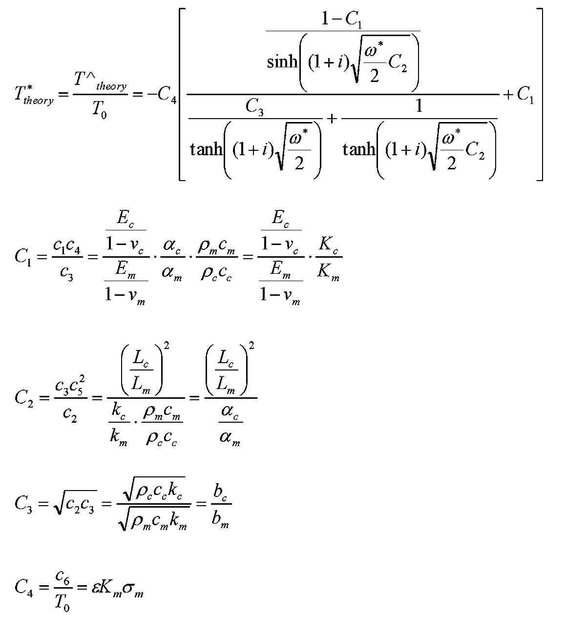
- the one-dimensional heat conduction equation used in the information processing apparatus 50 of the present embodiment is as shown in the following formula (1).
- the temperature T ⁇ theory represents a value obtained by Fourier transforming the temperature.
- the theoretical solution of the temperature is indicated by a non-dimensional expression (T * theory ) using the initial temperature T 0 and the temperature T theory .
- the four dimensionless constants C 1 to C 4 are respectively expressed as follows.
- inverse analysis is performed using a function T * theory (C 1 , C 2 , C 3 , C 4 ) of four parameters as a model function based on the formula (1).
- T * theory C 1 , C 2 , C 3 , C 4
- the temperature (non-dimensionalized) amplitude A * theory and phase ⁇ theory of the coating surface temperature are expressed by the following equations.
- C 1 0.80
- C 2 0.05
- the C 3 1.50
- the coating surface temperature of the case of C 4 0.005 amplitude and phase in FIGS. 5A and 5B.
- the amplitude of the vertical axis is made dimensionless.
- the horizontal axis indicates a dimensionless angular frequency and is displayed logarithmically.
- the information processing apparatus 50 performs a reverse analysis for identifying the principal stress sum of the substrate from the measurement data of the temperature fluctuation of the coating surface by the infrared camera 30 using the theoretical solution of the temperature of the coating surface.
- the information processing apparatus 50 needs to solve a four-dimensional inverse problem with C 1 , C 2 , C 3 , and C 4 in Equation (1) as variables.
- the main stress sum of the substrate can be obtained by substituting the identified value of the C 4 to equation (2d). Further, if the identification values of C 2 and C 3 are used, the thermal property value and the film thickness Lc of the coating can be identified.
- an inverse problem for obtaining C 1 , C 2 , C 3 , and C 4 from the temperature measurement data of the coating surface based on the temperature image of the infrared camera 30 using the theoretical solution of the coating surface temperature.
- the objective function of the square problem is defined.
- the temperature of the coating surface is measured by infrared thermography, and temperature amplitude (A i ) and phase lag ( ⁇ i ) data are acquired.
- T 0 is the initial temperature of the substrate and the coating material.
- the objective function F is defined as follows as the residual sum of squares between the model function T * i and dimensionless temperature data b * i.
- the trust region method can be used when there is no restriction
- the trust region reflective method can be used when there is a restriction.
- “when there is a restriction” means a case where the physical property values constituting the variable can be measured in advance or a possible range is known.
- the film thickness L c of the coating material may be measured in advance.
- “When there is no restriction” means a case where physical property values constituting a variable cannot be measured in advance or a possible range is not known.
- the inverse problem of the objective function F defined by the equation (6) is considered to have a large nonlinearity from the form of the equation (5).
- Formula (5) there are many local minimum values, and there is a case where an appropriate initial point cannot be set. Therefore, the inventors of the present application investigated in advance the relationship between the range of each parameter and the probability of obtaining a solution.
- Information indicating the result is stored in the data storage unit 57 of the information processing apparatus 50 as a reference table 57b.
- the inventors of the present application show that the range of each parameter of ⁇ * , C 1 to C 4 and the value of the maximum error e max obtained when inverse analysis is performed using the values within these ranges are 10% or less.
- Information indicating this relationship is stored as a reference table in the data storage unit 57 of the information processing apparatus 50.
- this reference table showing the relationship between the range of each parameter and the probability that the value of the maximum error e max is 10% or less is referred to as a “first reference table”.
- a first reference table is prepared for each of a plurality of ranges of ⁇ * .
- FIG. 6 is a diagram showing an example of a first reference table for a range of ⁇ * of 1 ⁇ 10 2 to 1 ⁇ 10 4 .
- the information processing apparatus 50 also includes a first reference table for other ⁇ * ranges.
- ⁇ * is 1 ⁇ 10 2 to 1 ⁇ 10 4
- C 1 is 1 ⁇ 10 0 to 1 ⁇ 10 1
- C 2 is 1 ⁇ 10 ⁇ 4 to 1
- the maximum error The probability that e max is less than 10% is 51%. This indicates that the probability that C 1 to C 4 can be accurately identified is low.
- ⁇ * is 1 ⁇ 10 2 to 1 ⁇ 10 4
- C 1 is 1 ⁇ 10 ⁇ 1 to 1 ⁇ 10 0
- C 2 is 1 ⁇ 10 ⁇ 3 to 1 ⁇ 10 ⁇ 2
- C 3 is 1 ⁇ 10.
- the inventors of the present application have the range of each parameter of ⁇ * , C 1 to C 4 and the value of the error e 4 related to C 4 obtained when the inverse analysis is performed using the values within those ranges.
- the relationship with the probability of being 10% or less was investigated.
- Information indicating this relationship is stored as a reference table in the data storage unit 57 of the information processing apparatus 50.
- the range of each parameter, the reference table showing the relationship between the probability that the value of the error e 4 about C 4 becomes 10% or less as "second reference table”.
- a second reference table is prepared for each of a plurality of ranges of ⁇ * .
- FIG. 7 shows an example of the second reference table.
- Figure 7 is a diagram illustrating an example of a second reference table for a range of omega * of 1 ⁇ 10 -2 ⁇ 1 ⁇ 10 0.
- the information processing apparatus 50 also includes a second reference table for other ⁇ * ranges.
- ⁇ * is 1 ⁇ 10 ⁇ 2 to 1 ⁇ 10 0
- C 1 is 1 ⁇ 10 0 to 1 ⁇ 10 1
- C 2 is 1 ⁇ 10 ⁇ 3 to 1 ⁇ .
- C 3 is 1 ⁇ 10 -3 ⁇ 1 ⁇ 10 -2
- C 4 was subjected to reverse analyzed using the values in the range of 1 ⁇ 10 -3 ⁇ 1 ⁇ 10 -2, the error
- the probability that e 4 is less than 10% is 100%. This indicates that the probability that C 4 can be accurately identified is very high.
- the“ second reference table ” may be used in the principal stress sum calculation process. Towards the second lookup table, than the first reference table, a wide application range of coating material can be identified accurately C 4.
- thermophysical properties of the coating film it is necessary to identify the C 2 accurately. Further, in order to calculate the thickness of the coating film, it is necessary to identify the C 3 accurately. Therefore, the following ⁇ 1-2-2. As described in Calculation Method of Thermophysical Property Value or Film Thickness of Coating Film> In the calculation process of the thermal property value or film thickness of the coating film, it is necessary to use the “first reference table”.
- FIG. 8 is a flowchart illustrating the principal stress sum calculation process in the information processing apparatus 50.
- the principal stress sum calculation process will be described below with reference to this flowchart. This process is executed by the controller 51 of the information processing apparatus 50.
- the controller 51 will first physical properties of the substrate material ( ⁇ m, c m, k m, ⁇ m, E m, v m) and the thickness (L m) to get (step S11).
- the physical property values of the substrate material and the coating material can be given in various data formats. These data may be input by the user via the operation unit 55, or may be input to the information processing apparatus 50 via the network 200.
- the controller 51 obtains approximate values of physical properties ( ⁇ c , c c , k c , ⁇ c , E c , v c ) and thickness (L c ) of the coating material (step S12).
- the exact value of the physical property value of the coating material is difficult to obtain, so an approximate value (to the extent that the order is understood) is sufficient.
- FIG. 9 shows physical property values ( ⁇ , c p , k, ⁇ , E, v) for various substrates and coating materials.
- ⁇ density
- c p constant pressure specific heat
- k thermal conductivity
- ⁇ linear expansion coefficient
- E longitudinal elastic modulus
- v Poisson's ratio
- ⁇ B tensile strength.
- As the substrate material two to three kinds of representative materials from metals, ceramics, and polymer materials are shown. Values of black paint and polyimide are shown as the coating material. Further, since the main component of the black paint is silicon resin, physical property values of the silicon resin are also shown as reference values.
- the controller 51 calculates the possible range of the parameters ⁇ * and C 1 to C 4 (step S13).
- the controller 51 for the variable C 1 ⁇ C 4, calculates a range that can be respectively taken from the formula (2a) ⁇ (2d).
- FIG. 10 shows the possible ranges of variables C 1 to C 4 when ABS, SUS304, and A5052 are used as the substrate material. Further, the controller 51 calculates the range of the omega * with the vibration frequency f based on the following equation, the thickness L m, the thermal diffusivity a m.
- the controller 51 selects one table from a plurality of second reference tables (see FIG. 7) based on the range of the angular frequency ⁇ * (step S14).
- the controller 51 determines whether or not the probability for the area corresponding to each of the variables C 1 to C 4 in the selected table is a predetermined value (for example, 70%) or more (step S15).
- a predetermined value for example, 70%
- the probability (e 4 ) for the variable C 4 is 100% in a wide area.
- the predetermined value is set to 70%, for example.
- step S15 If the probability for the corresponding area is less than the predetermined value (NO in step S15), the physical property value and thickness of the coating material are newly set by the user (step S20), and the process returns to step S13. Thereby, the range of each variable is reset, and the second reference table is selected again.
- step S15 if the probability for the corresponding region is equal to or greater than the predetermined value (YES in step S15), the controller 51 changes the values of the variables C 1 to C 4 within the range defined by the selected second reference table. A reverse analysis is performed using (7) to identify variables C 1 to C 4 (step S16).
- the controller 51 calculates the principal stress sum ⁇ m using the equation (8a) based on C 4 (step S17). Thus, the principal stress sum ⁇ m is obtained.
- the infrared image by the infrared camera 30 includes noise. Therefore, the value of C 4 obtained by inverse analysis is smaller than the noise level, the value is distinguished from the noise Tsukazu considered and reliability is low. On the other hand, if the value of C 4 obtained by inverse analysis is higher than the noise level, the value is not influenced by noise, is considered to be reliable is high.
- the controller 51 determines whether or not the value of C 4 is a predetermined value (for example, 1 ⁇ 10 ⁇ 4 ) or more (step S18).
- the predetermined value is set to be equal to or higher than the noise level of the infrared camera 30.
- the controller 51 determines that the obtained values of C 1 to C 4 are not affected by noise (step S19).
- the controller 51 determines that the obtained values of C 1 to C 4 (identification values) are affected by noise (step S21).
- This determination result may be displayed on the display unit 53 of the information processing apparatus 50, or may be stored in the data storage unit 57 in association with a value obtained as a flag indicating the determination result.
- the principal stress sum ⁇ m of the substrate material of the test piece 1 can be obtained based on the data of the infrared image of the test piece 1.
- FIG. 11 is a flowchart showing the calculation process of the thermal property value or film thickness of the coating film in the information processing apparatus 50.
- thermophysical property value or film thickness calculation process of the coating film will be described with reference to this flowchart. This process is executed by the controller 51 of the information processing apparatus 50.
- the controller 51 will first physical properties of the substrate material ( ⁇ m, c m, k m, ⁇ m, E m, v m) and the thickness (L m) to get (step S31).
- the controller 51 obtains approximate values of physical properties ( ⁇ c , c c , k c , ⁇ c , E c , v c ) and thickness (L c ) of the coating material (step S32).
- the exact value of the physical property value of the coating material is difficult to obtain, so an approximate value (to the extent that the order is understood) is sufficient.
- the controller 51 calculates a possible range of angular frequency omega * and variable C 1 ⁇ C 4 (step S33).
- the controller 51 selects one table from a plurality of first reference tables (see FIG. 6) based on the range of the angular frequency ⁇ * (step S34).
- the controller 51 determines whether or not the probability for the region corresponding to each of the variables C 1 to C 4 in the selected first reference table is equal to or higher than a predetermined value (for example, 70%) (step S35).
- a predetermined value for example, 70%
- step S40 determines whether or not the load can be increased (ie, C 4 ) (step S40). ). When the load (C 4 ) can be increased (YES in step S40), the controller 51 increases C 4 (step S41) and returns to step S32. On the other hand, if the load (C 4 ) cannot be increased (NO in step S40), the controller 51 newly sets the physical property value and thickness of the substrate and coating material (step S42), that is, the value of C 2 is adjusted. Then, the process returns to step S32. Thereby, the range of each variable is reset, and the first reference table is selected again.
- the controller 51 changes the values of the variables C 1 to C 4 within the range defined by the selected first reference table.
- a reverse analysis is performed using (7) to identify variables C 1 to C 4 (step S36).
- the controller 51 calculates the thermal property value or the film thickness of the coating material based on C 2 and C 3 (step S37). That is, if any one of the thermophysical property value and the film thickness of the coating material is known, the thermophysical property value and the film are determined using C 2 and C 3 and the known value of the thermophysical property value and the film thickness. An unknown value of the thickness can be determined.
- the controller 51 determines whether it (step S38).
- the predetermined value is set to be equal to or higher than the noise level of the infrared camera 30. If the value of C 4 is equal to or greater than the predetermined value (YES in step S38), the controller 51 determines that the obtained values of C 1 to C 4 are not affected by noise (step S39). On the other hand, if the value of C 4 is less than the predetermined value (NO in step S38), the controller 51 determines that the obtained values of C 1 to C 4 (identification values) are affected by noise (step S43).
- test piece 1 not only the principal stress sum but also the physical property value of the coating material to be measured (test piece 1) can be measured.
- a hydraulic servo fatigue tester “L10kN” manufactured by Shimadzu Corporation was used.
- mold of Shimadzu Corporation was used as the control device 15 of the shaker 10.
- FIG. As the infrared camera 30, an infrared thermography “Silver 480M” of Cedip Infrared Systems was used.
- test piece obtained by coating two kinds of substrate materials, ABS and SUS304, with a black paint and a test piece obtained by coating an aluminum substrate material with a polyimide tape were used.
- ABS substrate three types of test pieces having different coating film thicknesses were prepared.
- SUS304 substrate five types of test pieces having different coating film thicknesses were prepared.
- substrate material of aluminum A5052
- A5052-1 and A5052-2 two types of test pieces having different coating film thicknesses (55 ⁇ m and 110 ⁇ m) were prepared.
- the load conditions are as follows. The stress ratios are all zero.
- the load amplitude (both amplitudes) is 0.1 kN for the ABS substrate, 3.0 kN for the SUS304 substrate, and 3.0 kN for the A5052 substrate.
- the excitation frequency f is 1, 3, 5, 10, 15, 20, 25, 30 Hz. Tests were also conducted at 35, 40 Hz only for A5052-2.
- the shooting conditions of the infrared camera 30 are as follows.
- the frame rate was 249 Hz, and 2000 frames were taken for each excitation frequency.
- Temperature fluctuation and phase data obtained by the infrared camera 30 is converted into temperature amplitude and temperature phase (phase delay) at each frequency by Fourier transform for each pixel at the excitation frequency in the information processing device 50. .
- 12A and 12B show the temperature amplitude A [K] and the temperature phase (phase delay) ⁇ [rad] for the test piece of the ABS substrate, respectively.
- 13A and 13B show the temperature amplitude A [K] and the temperature phase (phase delay) ⁇ [rad] for the test piece of the SUS304 substrate, respectively.
- 14A and 14B show the temperature amplitude A [K] and the temperature phase (phase delay) ⁇ [rad] for the test piece of the A5052 substrate, respectively.
- FIG. 15 shows the four parameters identified as described above, the principal stress sum (stress amplitude) calculated from them, and the film thickness of the coating material.
- the stress measurement method is a method for measuring the stress of a measurement object including a substrate and a coating film.
- the test piece 1 (measurement object) is vibrated at a plurality of vibration frequencies.
- the temperature amplitude of the test piece 1 is measured with the infrared camera 30 (temperature sensor).
- a one-dimensional heat conduction equation showing the theoretical solution of the temperature amplitude of the coating film surface based on the heat conduction and thermoelastic effect of both the substrate and the coating film (see equations (1), (2a) to (2d))
- the parameters of the heat conduction equation are identified by performing curve fitting on the measured value of the temperature amplitude with respect to the frequency characteristics of the temperature change component and the phase component based on the thermoelastic effect obtained by a plurality of vibration frequencies.
- the stress of the test piece 1 is calculated
- the curve fitting is a fitting by the least square method.
- a trust region method or a trust region reflective method is used as the least square method.
- the stress measurement method holds a reference table (an example of table information) indicating the possible ranges of parameters of the heat conduction equation for different vibration frequencies for a plurality of combinations of substrates and coating films.
- a reference table an example of table information
- the range that can be taken by the parameters of the heat conduction equation is set with reference to the reference table, and curve fitting is performed while changing the parameters within the set range.
- the identification values of the variables C 1 to C 4 can be obtained accurately and reliably.
- the stress measurement method of the present embodiment further includes obtaining the thermal property or film thickness of the coating film based on the identified parameter.
- the stress measurement device is a stress measurement device that obtains a stress value of a measurement object based on a temperature amplitude image of the measurement object composed of a substrate and a coating film.
- the stress measurement apparatus includes a device interface 58 (an example of an acquisition unit) that acquires a temperature amplitude, and a controller 51 (an example of a control unit) that calculates a stress of the test piece 1 (an example of a measurement object) based on a temperature amplitude image. .
- the controller 51 obtains a measured value of the temperature amplitude of the coating film surface based on the thermal conduction and thermoelastic effect of both the substrate and the coating film from the temperature amplitude, and based on a one-dimensional heat conduction equation indicating a theoretical solution of the coating film surface. Then, with respect to the frequency characteristics of the temperature change component and the phase component based on the thermoelastic effect obtained by a plurality of different vibration frequencies, a curve fitting is performed on the measured value of the temperature amplitude to obtain a heat conduction equation ((Equation (1), (2a ) To (2d))))))) are identified, and the stress of the measurement object is obtained based on the identified parameters.
- the present embodiment also discloses a stress measurement system for a measurement object composed of a substrate and a coating film.
- the stress measurement system 100 is a system that vibrates a measurement object composed of a substrate and a coating film, measures the temperature amplitude of the measurement object, and obtains the stress value of the measurement object from the measurement result. is there.
- the stress measurement system 100 includes an exciter 10 that repeatedly applies a load to a test piece 1 (an example of an object to be measured) at a predetermined frequency, and an infrared ray that measures the temperature amplitude of the test piece 1 to which the load is applied.
- a camera 30 an example of a temperature sensor
- an information processing device 50 an example of a stress measurement device that obtains stress of a measurement object based on a temperature image obtained from the infrared camera 30 are provided.
- the controller 51 is a one-dimensional heat conduction equation (see (Equations (1), (2a) to (2d)) showing a theoretical solution of the temperature amplitude of the coating film surface based on the heat conduction and thermoelastic effects of both the substrate and the coating film. ))
- To identify the parameters of the heat conduction equation by performing curve fitting to the temperature amplitude measurement for the frequency characteristics of the temperature change component and phase component based on the thermoelastic effect obtained by multiple vibration frequencies, Based on the identified parameters, the stress of the measurement object is obtained.
- the first embodiment has been described as an example of the technique disclosed in the present application.
- the technology in the present disclosure is not limited to this, and can also be applied to an embodiment in which changes, replacements, additions, omissions, and the like are appropriately performed.
- the substrate or coating material of the measurement object (test piece) described above is an example, and the idea of the present disclosure can be applied to the measurement object configured from various substrates and coating materials.
- control program executed by the controller 51 may be provided to the information processing apparatus 50 via the network 200, or may be installed from a recording medium such as a CD-ROM.
- the controller 51 may be a dedicated circuit designed to realize its function with only a hardware circuit.
- the controller 51 may include not only a CPU and MPU, but also a DSP (Digital Signal Processor), an FPGA (Field-Programmable Gate Array), an ASIC (Application Specific Integrated Circuit), and the like.
- an infrared camera capable of acquiring a temperature image is used as the temperature sensor.
- the temperature sensor in the present disclosure is not limited to the infrared camera.
- a contact or non-contact temperature sensor may be used to measure the stress of the measurement object based on the temperature amplitude at a specific point.
- the present disclosure can be applied to a measurement apparatus that measures the stress of a measurement target including a substrate and a coating film based on an infrared image.
- Test piece (measurement object) 10 Exciter 30 Infrared camera (temperature sensor) 40 Function generator 50 Information processing device (stress measuring device) 51 Controller (Calculation unit) 57 Data storage unit 57b Reference table (table information) 100 Stress measurement system
Landscapes
- General Physics & Mathematics (AREA)
- Physics & Mathematics (AREA)
- Chemical & Material Sciences (AREA)
- Analytical Chemistry (AREA)
- Biochemistry (AREA)
- Life Sciences & Earth Sciences (AREA)
- Health & Medical Sciences (AREA)
- General Health & Medical Sciences (AREA)
- Immunology (AREA)
- Pathology (AREA)
- Engineering & Computer Science (AREA)
- Computer Vision & Pattern Recognition (AREA)
- Investigating Or Analyzing Materials Using Thermal Means (AREA)
- Radiation Pyrometers (AREA)
Abstract
応力測定方法は、測定対象物を複数の振動周波数で加振し、温度センサで測定対象物の温度振幅を測定する。そして、基板とコーティング膜両方の熱伝導および熱弾性効果に基づくコーティング膜表面の温度振幅の理論解を示す下記の一次元の熱伝導方程式に基づいて、複数の振動周波数によって得られる熱弾性効果に基づく温度変化成分および位相成分の周波数特性に関して、温度振幅の測定値に対するカーブフィッティングを行うことによって熱伝導方程式のパラメータを同定する。そして、同定したパラメータに基づき測定対象物の応力を求める。
Description
本開示は、引張あるいは圧縮応力を測定対象物に繰返し加え、この測定対象物の温度振幅を温度センサによって測定し、この測定結果から測定対象物の応力値を求める応力測定方法、応力測定装置および応力測定システムに関する。
従来、コーティングされた基板を含む測定対象物を複数の周波数で加振し、その際に熱弾性効果による生じる表面温度の変化を測定し、その測定データに基づき測定対象物の応力を測定する赤外線応力測定の補正方法として、種々の方法が報告されている(例えば、非特許文献1~非特許文献3参照)。
非特許文献1には、コーティング膜が塗布された測定対象物の応力補正方法が記載されている。コーティング膜の膜厚が測定対象物の基板に比べて薄いため、基板の温度とコーティング膜の温度はそれぞれ一様と仮定する。その条件の下で熱伝導方程式を解くことで加振周波数によって減衰する応力値の補正を行っている。ただし、熱弾性効果による発熱は基板のみで発生し、コーティング膜の熱弾性効果による発熱は無いと仮定している。加振周波数増加により、測定対象物の測定応力が減衰する要因は、基板からコーティング膜への移動熱量が周波数の増加に伴い減少することに起因することが記載されている。
非特許文献2では、正弦波状の温度変動が生じている場合を仮定し,一次元熱伝導方程式をもとに検討を行い、非特許文献1と同様の結果を得ている。ただし、非特許文献2はコーティング自体の熱弾性効果による発熱は無視できると仮定している。
非特許文献3は、コーティングの熱弾性効果に起因する発熱についても検討を行っている。金属基板上に十分に薄いコーティングが塗布された場合を仮定し、温度波理論(Thermal wave theory)を用いて、基板から伝わる波がコーティング内を伝播し基板とコーティングの界面および外表面で反射するものとした。そして,温度波の和から厚さ方向の温度分布を求めている。
非特許文献1~3では、前提条件としてコーティング膜の熱弾性効果による発熱現象や基板の厚み、熱伝導状態などが考慮されていない。このため、低熱伝導基板や基板とコーティング膜の物性値が近い条件下では、実績で生じる加振周波数にともなうコーティング膜表面の温度減衰を理論計算で忠実に表現することが不可能であった。その結果、測定して得られた応力値の減衰を完全に補正することができなかった。
特許文献1はこのような問題を解決する応力測定方法を開示する。特許文献1の応力測定方法は、基板とコーティング膜の両方の熱伝導および熱弾性効果に基づく一次元の熱伝導方程式から求められるコーティング膜表面の温度振幅の理論解を導出する。そして、複数の振動周波数によって得られる熱弾性効果に基づく温度変化成分および位相成分の周波数特性に対して、理論解を最小二乗法によりカーブフィッティングさせる。そのことによってコーティング膜表面の理論解の変数を同定し、コーティング膜による熱伝導の影響を補正する。これにより、正確な応力値を求めることを可能としている。
M.H.Belgen,infrd-red radi/metric stress instrumentation application range study.,NASA Report CR-1067(1967)
J.Mckelvie,Consideration of the surface temperature response to cyclic thermoelastic heat generation, SPIE Vol.731 stress Analysis by Thermoelastic Techniques (1987)44-53.
A.K.Mackenzie,Effects Of Surface Coatings On Infra-Red Measurements of Thermoelastic Responses, SPIE Vol.1084 Stress and Vibration.Recent Developments in Indudtrial Measurement and Analysis (1989)59-71.
本開示は、基板とコーティング膜から構成される測定対象物の応力を精度良く測定できる応力測定方法、応力測定装置および応力測定システムを提供する。
本開示の第1の態様において、基板とコーティング膜から構成される測定対象物の応力の測定方法が提供される。その測定対象物の応力の測定方法は、測定対象物を複数の振動周波数で加振する。そして、温度センサで測定対象物の温度振幅を測定する。そして、基板とコーティング膜両方の熱伝導および熱弾性効果に基づくコーティング膜表面の温度振幅の理論解を示す下記の一次元の熱伝導方程式に基づいて、複数の振動周波数によって得られる熱弾性効果に基づく温度変化成分および位相成分の周波数特性に関して、温度変動の測定値に対するカーブフィッティングによって熱伝導方程式のパラメータを同定する。そして、同定したパラメータに基づき測定対象物の応力を求める。
ここで、T0は基準温度、T^theoryは温度のフーリエ変換、Eは縦弾性係数、Kは熱弾性定数、vはポアソン比、cは定圧比熱、kは熱伝導率、ρは密度、αは線膨張係数、Lは膜厚であり、添字のmは基板、添字のcはコーティング膜をそれぞれ示す。
本開示の第2の態様において、加振された、基板とコーティング膜から構成される測定対象物の温度振幅に基づき、測定対象物の応力値を求める応力測定装置が提供される。応力測定装置は、温度振幅を取得する取得部と、温度振幅に基づき測定対象物の応力を算出する制御部と、を備える。制御部は、温度振幅から、基板とコーティング膜両方の熱伝導および熱弾性効果に基づくコーティング膜表面の温度振幅の測定値を求める。さらに、制御部は、コーティング膜表面の理論解を示す上記の一次元の熱伝導方程式に基づいて、複数の振動周波数によって得られる熱弾性効果に基づく温度変化成分および位相成分の周波数特性に関して、温度振幅の測定値に対するカーブフィッティングを行うことによって熱伝導方程式のパラメータを同定する。そして、制御部は、同定したパラメータに基づき測定対象物の応力を求める。
本開示の第3の態様において、基板とコーティング膜から構成される測定対象物を加振し、測定対象物の温度振幅を測定し、測定結果から測定対象物の応力値を求める応力測定システムが提供される。応力測定システムは、測定対象物に対して荷重を所定の周波数で繰り返して加える加振機と、荷重が加えられている測定対象物の温度振幅を測定する温度センサと、温度センサから得た温度振幅に基づき測定対象物の応力を求める情報処理装置と、を備える。情報処理装置は、基板とコーティング膜両方の熱伝導および熱弾性効果に基づくコーティング膜表面の温度振幅の理論解を示す上記の一次元の熱伝導方程式に基づいて、複数の振動周波数によって得られる熱弾性効果に基づく温度変化成分および位相成分の周波数特性に関して、温度振幅の測定値に対するカーブフィッティングによって熱伝導方程式のパラメータを同定し、同定したパラメータに基づき測定対象物の応力を求める。
本開示によれば、基板とコーティング膜から構成される測定対象物の応力を精度良く測定できる。
以下、適宜図面を参照しながら、実施の形態を詳細に説明する。但し、必要以上に詳細な説明は省略する場合がある。例えば、既によく知られた事項の詳細説明や実質的に同一の構成に対する重複説明を省略する場合がある。これは、以下の説明が不必要に冗長になるのを避け、当業者の理解を容易にするためである。
なお、発明者らは、当業者が本開示を十分に理解するために添付図面および以下の説明を提供するのであって、これらによって請求の範囲に記載の主題を限定することを意図するものではない。
(実施の形態1)
本実施の形態の応力測定システムは、基板と基板表面に塗布されたコーティング材とを含む測定対象物の主応力和を測定するシステムである。具体的には、基板とコーティング材両方の熱伝導および熱弾性効果を考慮した一次元の熱伝導方程式から求められるコーティング膜表面の温度振幅の理論解を導出する。そして、理論解を、複数の振動周波数の加振により得られた測定データから得られる、熱弾性効果に基づく温度変化成分および位相成分の周波数特性に対してカーブフィッティングさせる。これによって、コーティング膜表面の理論解の各変数(係数)を同定し、同定した変数から測定対象物の主応力和や基板材料の物性値を求める。
本実施の形態の応力測定システムは、基板と基板表面に塗布されたコーティング材とを含む測定対象物の主応力和を測定するシステムである。具体的には、基板とコーティング材両方の熱伝導および熱弾性効果を考慮した一次元の熱伝導方程式から求められるコーティング膜表面の温度振幅の理論解を導出する。そして、理論解を、複数の振動周波数の加振により得られた測定データから得られる、熱弾性効果に基づく温度変化成分および位相成分の周波数特性に対してカーブフィッティングさせる。これによって、コーティング膜表面の理論解の各変数(係数)を同定し、同定した変数から測定対象物の主応力和や基板材料の物性値を求める。
[1-1.構成]
以下、添付の図面を参照して本開示に係る応力測定システムの実施の形態を説明する。
以下、添付の図面を参照して本開示に係る応力測定システムの実施の形態を説明する。
図1は、実施の形態1における応力測定システムの構成を示した図である。応力測定システム100は、加振機10と、コントロールデバイス15と、ファンクションジェネレータ40と、を備える。加振機10は、本開示に係る測定対象物の一例である試験片1を所定の周波数で加振する。コントロールデバイス15は、加振機10の加振動作を制御する。ファンクションジェネレータ40は、加振波形を出力する。
さらに、応力測定システム100は、赤外線カメラ30と、情報処理装置50(本開示に係る応力測定装置の一例)とを備える。赤外線カメラ30は、加振された試験片1の温度画像(赤外画像)を撮影する。情報処理装置50は、温度画像を解析し、試験片1の主応力和や物性値等を算出する。
ファンクションジェネレータ40の出力信号は、コントロールデバイス15とともに赤外線カメラ30にも入力される。コントロールデバイス15は、ファンクションジェネレータ40からの出力信号に基づき加振機10の加振周波数を制御する。これにより、赤外線カメラ30の撮影画像と試験片1に加えられる加振周波数とを同期させている。
図2は、情報処理装置50の内部構成を説明したブロック図である。情報処理装置50は例えばパーソナルコンピュータである。情報処理装置50は、その全体動作を制御するコントローラ51と、情報を表示する表示部53と、ユーザが操作を行う操作部55と、データやプログラムを記憶するRAM(Random Access Memory)56及びデータ格納部57とを備える。
情報処理装置50はさらに、赤外線カメラ30等の外部機器に接続するための機器インタフェース58(本開示に係る取得部の一例)と、ネットワークに接続するためのネットワークインタフェース59(本開示に係る取得部の一例)とを含む。機器インタフェース58は、USB(Universal Serial Bus)、HDMI(登録商標)(High-Definition Multimedia Interface)、IEEE1394等に準拠してデータ等の通信を行う通信モジュール(回路)である。ネットワークインタフェース59は、IEEE802.11、WiFi、Bluetooth(登録商標)、3G、4G、LTE(Long Term Evolution)等の規格に準拠してデータ通信を行う通信モジュール(回路)である。
コントローラ51(演算部の一例)はCPU(Central Processing Unit)やMPU(Micro-Processing Unit)で構成され、データ格納部57に格納された所定の制御プログラム57aを実行することにより所定の機能を実現する。
表示部53は、例えば液晶表示ディスプレイまたは有機ELディスプレイである。
RAM56はプログラムやデータを一時的に格納する記憶素子であり、コントローラ51の作業領域として機能する。
データ格納部57は機能を実現するために必要なパラメータ、データ及びプログラムを記憶する記録媒体であり、コントローラ51で実行される制御プログラムや各種のデータを格納している。データ格納部57は、例えば、ハードディスクドライブ(HDD)、SSD(Solid State Drive)、光ディスク媒体で構成される。データ格納部57には制御プログラム57aがインストールされている。コントローラ51はこの制御プログラム57aを実行することで後述する機能を実現する。データ格納部57はコントローラ51の作業領域としても機能する。
データ格納部57は、測定データと、測定データに対するフィッティングを行う際に参照される参照テーブル57bとを格納する。参照テーブル57bは、角周波数及び一次元の熱伝導方程式の係数の各範囲の組み合わせ毎に正しい解が得られる確率を示したテーブルである(詳細は後述)。
[1-2.動作]
以上のように構成された応力測定システム100について、その動作を以下説明する。
以上のように構成された応力測定システム100について、その動作を以下説明する。
本実施の形態では、片面にコーティングを施した一定厚さLmの基板に一様な単軸の正弦波状応力が生じる場合について、厚さ方向の一次元熱伝導の理論解析を行い、コーティング表面温度の理論解を導出する。
図3Aは、本実施形態における、厚さ方向の熱伝導のみを考慮した一次元の単軸引張りの理論解析モデルを示す図である。図3Aに示すように基板の片面にコーティングが施されている測定対象物について、基板外表面(基板とコーティングの界面)に原点をとり、負荷方向をy軸、それに垂直な基板面内の方向をx軸、基板の厚さ方向をz軸とする。基板にはy軸方向の垂直応力のみが作用し、それはz軸方向に一様で大きさが正弦波状に変動する。コーティングは基板の変形に同期して変形すると考える。そして、コーティングに生じるひずみは基板のひずみと常に等しく、かつz軸方向に一様であると仮定する。すなわち、基板およびコーティングにおける応力振幅を図3Bに示すように仮定する。そして、基板およびコーティングにおけるひずみ振幅を図3Cに示すように仮定する。
本実施の形態の応力測定システム100による応力測定は以下の手順で行われる。
1)試験片の加振による温度特性の測定
試験片1を複数の加振周波数で加振し、そのときの測定対象物の表面温度の変化を赤外線カメラ30で測定する(測定データの取得)。
試験片1を複数の加振周波数で加振し、そのときの測定対象物の表面温度の変化を赤外線カメラ30で測定する(測定データの取得)。
2)一次元の熱伝導方程式の理論解による逆解析
次に、基板とコーティング材両方の熱伝導および熱弾性効果を考慮した一次元の熱伝導方程式から求められるコーティング膜表面の温度振幅の理論解を導出する。そして、複数の振動周波数の加振により得られた測定データから得られる、熱弾性効果に基づく温度変化成分および位相成分の周波数特性に対して、理論解をカーブフィッティングすることによって、一次元の熱伝導方程式の理論解の各変数(係数)を同定する。
次に、基板とコーティング材両方の熱伝導および熱弾性効果を考慮した一次元の熱伝導方程式から求められるコーティング膜表面の温度振幅の理論解を導出する。そして、複数の振動周波数の加振により得られた測定データから得られる、熱弾性効果に基づく温度変化成分および位相成分の周波数特性に対して、理論解をカーブフィッティングすることによって、一次元の熱伝導方程式の理論解の各変数(係数)を同定する。
3)主応力和等の算出
その後、同定した各変数から測定対象物の主応力和を求める。その際、同定した各変数から、測定対象物のコーティング材の物性値を求めることもできる。
その後、同定した各変数から測定対象物の主応力和を求める。その際、同定した各変数から、測定対象物のコーティング材の物性値を求めることもできる。
以下、上記の各手順(1)~(3)をより具体的に説明する。
(1)試験片の加振による温度特性の測定
測定対象物としての試験片1は、基板と、その表面に形成されたコーティング膜とから構成される。試験片1は加振機10にセットされる。コントロールデバイス15は、ファンクションジェネレータ40からの加振信号に基づき加振機10を制御する。具体的には、コントロールデバイス15は、複数種類の加振周波数のそれぞれで、加振機10が引張あるいは圧縮応力を試験片1に繰返し加えるように加振機10を制御する。
測定対象物としての試験片1は、基板と、その表面に形成されたコーティング膜とから構成される。試験片1は加振機10にセットされる。コントロールデバイス15は、ファンクションジェネレータ40からの加振信号に基づき加振機10を制御する。具体的には、コントロールデバイス15は、複数種類の加振周波数のそれぞれで、加振機10が引張あるいは圧縮応力を試験片1に繰返し加えるように加振機10を制御する。
赤外線カメラ30は、各加振周波数に対して、引張あるいは圧縮応力が加えられている試験片1を撮影して温度画像を生成する。赤外線カメラ30で測定した温度画像は、フーリエ変換機能を有する情報処理装置50でデータ処理される。情報処理装置50は、赤外線カメラ30により撮影された温度画像(赤外画像)に基づき、試験片1(基板)の主応力和及び物性値等を求める。
具体的には、情報処理装置50は、赤外線カメラ30から時間的に連続して温度画像を取り込む、そして、情報処理装置50は、その温度画像に対して画素毎にフーリエ変換を行うことにより、温度振幅データと温度位相データとを生成する。図4Aは、このようにして得られた温度振幅データの一例である。図4Bは温度位相データ(位相遅れ)の一例である。図4Aおよび図4Bに示す結果は、黒色塗料のコーティングが施されたABS(Acrylonitrile Butadiene Styrene)樹脂基板を含む試験片に対するものである。図4A及び図4Bについて、No.1~No.3は、コーティング膜の厚さが異なる3種類の試験片のデータを示している。
(2)一次元の熱伝導方程式の理論解による逆解析
情報処理装置50は、以上のようにして測定データから求めた温度振幅データと温度位相データに対して、一次元の熱伝導方程式を用いてカーブフィッティングを行うことにより、一次元の熱伝導方程式の各変数を求める。以下、本実施の形態で用いる一次元の熱伝導方程式について説明する。
情報処理装置50は、以上のようにして測定データから求めた温度振幅データと温度位相データに対して、一次元の熱伝導方程式を用いてカーブフィッティングを行うことにより、一次元の熱伝導方程式の各変数を求める。以下、本実施の形態で用いる一次元の熱伝導方程式について説明する。
本実施の形態の情報処理装置50で使用される一次元の熱伝導方程式は下記式(1)のとおりである。次式では、温度T^theoryは温度をフーリエ変換した値を示す。温度の理論解は初期温度T0を用いて温度Ttheoryを無次元化した表現(T*
theory)で示している。

4つの無次元定数C1~C4はそれぞれ以下のように表される。
本開示では、式(1)に基づいて4つのパラメータの関数T*
theory(C1, C2, C3, C4)をモデル関数とした逆解析を行う。コーティング表面の温度の(無次元化された)振幅A*
theoryと位相φtheoryは次式で表される。

例として、C1=0.80,C2=0.05,C3=1.50,C4=0.005である場合のコーティング表面温度の振幅と位相を図5A及び図5Bに示す。図5Aにおいて縦軸の振幅は無次元化されている。また、図5A及び図5Bのいずれも横軸は無次元角周波数を示し、対数表示されている。
情報処理装置50は、コーティング表面の温度の理論解を用いて、赤外線カメラ30によるコーティング表面の温度変動の測定データから基板の主応力和を同定するための逆解析を行う。情報処理装置50は、基板の主応力和を同定する過程では、式(1)におけるC1,C2,C3,C4を変数とする四次元の逆問題を解く必要がある。基板の主応力和は、C4の同定値を式(2d)に代入することで求められる。また、C2,C3の同定値を利用すれば、コーティングの熱物性値および膜厚Lcを同定することができる。例えば、基板の熱容量ρmcm、熱伝導率kmおよび厚さLmが既知である場合、C2,C3が得られると、2つの熱物性値と厚さのうちの1つが既知であれば、残りの値を求めることができる。すなわち、本実施の形態では、逆解析によりC1,C2,C3,C4を求め、それらの値から基板の主応力和のみならず、コーティング材の熱物性値・膜厚も同定することができる。
本実施の形態は,コーティングの表面温度の理論解を用いて,赤外線カメラ30の温度画像に基づくコーティング表面の温度測定データからC1,C2,C3,C4を求める逆問題(非線形最小二乗問題)の目的関数を定義している。
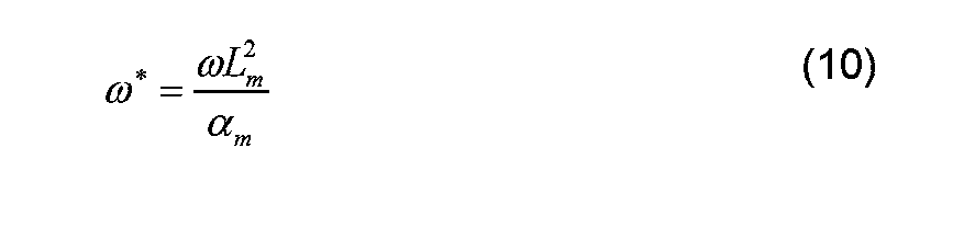
すなわち、コーティングが施された基板に、p通りの複数の加振周波数fi(i=1, 2, .., p)で単軸引張繰返し負荷を加える。赤外線サーモグラフィによりコーティング表面の温度測定を行い、温度振幅(Ai)と位相遅れ(φi)のデータを取得する。次に、一次元の熱伝導方程式(式(1)参照)の理論解をフィッティングに使用するために、得られたデータを以下のように変換する。まず、加振周波数fiはω=2πfに基づき無次元の角周波数ω*
iへ変換する。一方、温度振幅(Ai)と位相遅れ(φi)は無次元の温度データb*
iへ変換する。
ここで、T0は基板とコーティング材の初期温度である。以上より得られたデータ点(ω*
i, b*
i)(i=1, 2, ..., p)を逆解析に使用する。
一方,Cx=[C1,C2,C3,C4]Tを変数とするモデル関数T*
iを各ω*
i(i=1, 2, ..., p)に対して次のように定義する。
そして、目的関数Fを、モデル関数T*
iと無次元の温度データb*
iとの残差二乗和として以下のように定義する。
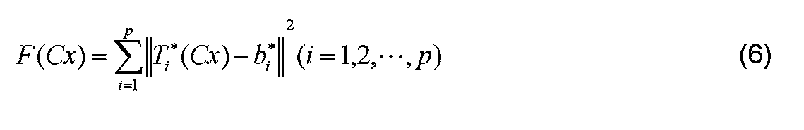
上式(6)において、F(Cx)が最小となるようなCxを最小二乗法により求めることにより、同定値Cx*=[C1
*, C2
*, C3
*, C4
*]T(すなわち、式(1)の変数C1~C4)を求める。最小二乗法としては、例えば、制約がない場合、信頼領域法を用いて、制約のある場合、信頼領域Reflective法を用いることができる。ここで、「制約のある場合」とは変数を構成する物性値が事前に測定できている場合や取りうる範囲がわかっている場合である。例えば、コーティング材の膜厚Lcは事前に測定できる場合もあるからである。「制約がない場合」とは変数を構成する物性値が事前に測定できない場合や取りうる範囲がわかっていない場合をいう。
(3)主応力和等の算出
C*xの同定値が求まれば、C4の同定値から基板の主応力和を式(2d)から求めることができる。また、コーティングの熱容量が既知の場合の熱拡散率および膜厚の同定値は、次式により求めることができる。
C*xの同定値が求まれば、C4の同定値から基板の主応力和を式(2d)から求めることができる。また、コーティングの熱容量が既知の場合の熱拡散率および膜厚の同定値は、次式により求めることができる。

式(6)により定義される目的関数Fの逆問題は、式(5)の形から非線形性が大きいと考えられる。すなわち、式(5)では極小値が数多く存在し、適切な初期点の設定も見当がつかない場合が考えられる。そこで、本願発明者らは、事前に、各パラメータの範囲と、解が得られる確率との関係を事前に調査した。その結果を示す情報は、参照テーブル57bとして情報処理装置50のデータ格納部57に格納されている。
本来、逆解析に使用するデータ点(ω*
i, b*
i)(i=1, 2, ..., p)は、測定により得る必要がある。しかし、ここでは、目的関数Fの性質を調査することを目的とするため、ある正解値C*xexactと無次元角周波数(ω*
i)(i=1, 2, ..., p)とを仮定して式(6)に代入することで、b*
i(=T*
i(Cx*
exact))を求め、その求めた値をデータ点とした。この一連の操作を順解析という。この順解析により生成されたデータ点を用いて逆解析を行い、変数C1~C4を同定した。そして、変数C1~C4の同定値と、それぞれの正解値との誤差enを求めた。
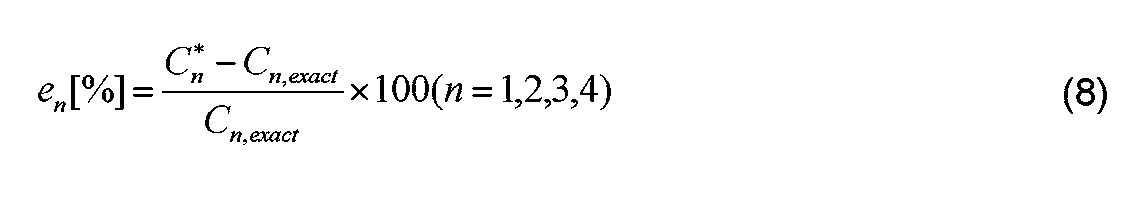
C1~C4に対する誤差en(n=1,2,3,4)の中で最大となる値を最大誤差emaxとした。

本願発明者らは、ω*,C1~C4の各パラメータの範囲と、それらの範囲内の値を用いて逆解析を行ったときに得られる最大誤差emaxの値が10%以下となる確率との関係を調査した。この関係を示す情報は情報処理装置50のデータ格納部57において、参照テーブルとして格納されている。以下、各パラメータの範囲と、最大誤差emaxの値が10%以下となる確率との関係を示すこの参照テーブルを「第1参照テーブル」という。本実施の形態では、複数のω*の範囲のそれぞれに対して第1参照テーブルを準備している。図6は、1×10²~1×10⁴のω*の範囲に対する第1参照テーブルの一例を示した図である。情報処理装置50は、図示していないが、他のω*の範囲に対する第1参照テーブルも備えている。
例えば、図6に示す第1参照テーブルを参照すると、ω*が1×10²~1×10⁴、C1が1×100~1×101、C2が1×10⁻⁴~1×10⁻³、C3が1×100~1×101、C4が1×10⁻⁴~1×10⁻³の範囲内にある値を用いて逆解析を行った場合、最大誤差emaxが10%未満となる確率は51%となる。これは精度よくC1~C4を同定できる確率が低いことを示している。一方、ω*が1×10²~1×10⁴、C1が1×10⁻¹~1×100、C2が1×10⁻³~1×10⁻²、C3が1×10⁻¹~1×100、C4が1×10⁻³~1×10⁻²の範囲内にある値を用いて逆解析を行った場合、最大誤差emaxが10%未満となる確率は97%となる。これは精度よくC1~C4を同定できる確率が非常に高いことを示している。
また、本願発明者らは、ω*,C1~C4の各パラメータの範囲と、それらの範囲内の値を用いて逆解析を行ったときに得られるC4に関する誤差e4の値が10%以下となる確率との関係を調査した。この関係を示す情報は情報処理装置50のデータ格納部57において、参照テーブルとして格納されている。以下、各パラメータの範囲と、C4に関する誤差e4の値が10%以下となる確率との関係を示すこの参照テーブルを「第2参照テーブル」という。本実施の形態では、複数のω*の範囲のそれぞれに対して第2参照テーブルを準備している。図7に第2参照テーブルの一例を示す。図7は、1×10⁻²~1×100のω*の範囲に対する第2参照テーブルの一例を示した図である。情報処理装置50は、図示していないが、他のω*の範囲に対する第2参照テーブルも備えている。
図7に示す第2参照テーブルを参照すると、ω*が1×10⁻²~1×100、C1が1×100~1×101、C2が1×10⁻³~1×10⁻²、C3が1×10⁻³~1×10⁻²、C4が1×10⁻³~1×10⁻²の範囲内にある値を用いて逆解析を行った場合、誤差e4が10%未満となる確率は100%となる。これは精度よくC4を同定できる確率が非常に高いことを示している。
ここで、主応力和を算出する場合は、C4を精度よく同定できればよい。そのため、以下の<1-2-1.主応力和の算出方法>で説明するように、主応力和の算出処理においては、「第2参照テーブル」を用いればよい。第2参照テーブルのほうが、第1参照テーブルよりも、精度よくC4を同定できるコーティング材料の適用範囲が広い。
一方、コーティング膜の熱物性値を算出する場合は、C2を精度よく同定する必要がある。また、コーティング膜の膜厚を算出するためには、C3を精度よく同定する必要がある。そのため、以下の<1-2-2.コーティング膜の熱物性値または膜厚の算出方法>で説明するように、コーティング膜の熱物性値または膜厚の算出処理においては、「第1参照テーブル」を用いる必要がある。
<1-2-1.主応力和の算出>
図8は、情報処理装置50における、主応力和の算出処理を示すフローチャートである。以下、このフローチャートを参照して主応力和の算出処理を説明する。この処理は情報処理装置50のコントローラ51により実行される。
図8は、情報処理装置50における、主応力和の算出処理を示すフローチャートである。以下、このフローチャートを参照して主応力和の算出処理を説明する。この処理は情報処理装置50のコントローラ51により実行される。
コントローラ51はまず、基板材料の物性値(ρm,cm,km,αm,Em,vm)と厚さ(Lm)を取得する(ステップS11)。基板材料やコーティング材の物性値等は種々のデータ形式で与えることができる。これらのデータはユーザにより操作部55を介して入力されてもよいし、ネットワーク200を介して情報処理装置50に入力されてもよい。
次にコントローラ51はコーティング材料の物性値(ρc,cc,kc,αc,Ec,vc)と厚さ(Lc)の概算値を取得する(ステップS12)。一般にコーティング材料の物性値の正確な値は、求めにくいので概算値(オーダーが分かる程度)でよい。
なお、図9に、各種の基板及びコーティング材に対する物性値(ρ,cp,k,α,E,v)を示す。ρは密度、cpは定圧比熱、kは熱伝導率、αは線膨張係数、Eは縦弾性係数、vはポアソン比、σBは引張り強さである。基板材料として、金属、セラミックス、高分子材料の中から代表的なものをそれぞれ2~3種類ずつ示している。コーティング材として、黒色塗料、ポリイミドの値を示している。また、黒色塗料の主成分はシリコン樹脂であるため、参考値としてシリコン樹脂の物性値も記している。
コントローラ51はω*とC1~C4それぞれのパラメータの取り得る範囲を算出する(ステップS13)。コントローラ51は、変数C1~C4については、式(2a)~(2d)からそれぞれの取り得る範囲を算出する。図10に、基板材料としてABS、SUS304、A5052を用いた場合の変数C1~C4の取り得る範囲を示す。また、コントローラ51は、下記式に基づき加振周波数f、厚さLm、熱拡散率amを用いてω*の範囲を算出する。
次に、コントローラ51は、角周波数ω*の範囲に基づき複数の第2参照テーブル(図7参照)の中から1つのテーブルを選択する(ステップS14)。
コントローラ51は、選択したテーブルにおいて各変数C1~C4が該当する領域に対する確率が所定値(例えば、70%)以上か否かを判断する(ステップS15)。ここで、第2参照テーブルを参照すると、変数C4に対する確率(e4)は広い領域で100%である。ここで、確率(e4)がおおよそ70%以上の場合に逆解析により精度良くC4が求められる場合が多い。よって、所定値は例えば70%に設定する。
該当する領域に対する確率が所定値未満の場合(ステップS15でNO)、ユーザにより新たにコーティング材の物性値や厚さが設定され(ステップS20)、ステップS13に戻る。これにより、各変数の範囲が再設定され、再度第2参照テーブルが選択される。
一方、該当する領域に対する確率が所定値以上の場合(ステップS15でYES)、コントローラ51は、選択した第2参照テーブルで規定される範囲内で変数C1~C4の値を変化させながら式(7)を用いて逆解析を行い、変数C1~C4を同定する(ステップS16)。
変数C1~C4の同定値が得られると、コントローラ51はC4に基づき式(8a)を用いて主応力和σmを算出する(ステップS17)。これにより主応力和σmが求まる。
ここで、赤外線カメラ30により赤外画像はノイズを含んでいる。よって、逆解析により得られたC4の値がそのノイズレベルよりも小さければ、その値はノイズとの区別がつかず、信頼性が低い値であると考えられる。一方、逆解析により得られたC4の値がノイズレベルよりも高ければ、その値はノイズの影響を受けておらず、信頼性が高い値であると考えられる。
コントローラ51は、主応力和σmの算出に加えて、C4の値が所定値(例えば、1×10⁻⁴)以上であるか否かを判断する(ステップS18)。所定値は赤外線カメラ30のノイズレベル以上に設定される。C4の値が所定値以上である場合(ステップS18でYES)、コントローラ51は、求まったC1~C4の値はノイズの影響なしと判定する(ステップS19)。一方、変数C4の値が所定値未満である場合(ステップS18でNO)、コントローラ51は、求まったC1~C4の値(同定値)はノイズの影響ありと判定する(ステップS21)。この判定結果は、情報処理装置50の表示部53上に表示してもよいし、判定結果を示すフラグとして求めた値に関連づけてデータ格納部57に格納してもよい。
以上のようにして、試験片1の赤外画像のデータに基づき試験片1の基板材料の主応力和σmを求めることができる。
<1-2-2.コーティング膜の熱物性値または膜厚の算出>
図11は、情報処理装置50における、コーティング膜の熱物性値または膜厚の算出処理を示すフローチャートである。以下、このフローチャートを参照して、コーティング膜の熱物性値または膜厚の算出処理を説明する。この処理は情報処理装置50のコントローラ51により実行される。
図11は、情報処理装置50における、コーティング膜の熱物性値または膜厚の算出処理を示すフローチャートである。以下、このフローチャートを参照して、コーティング膜の熱物性値または膜厚の算出処理を説明する。この処理は情報処理装置50のコントローラ51により実行される。
コントローラ51はまず、基板材料の物性値(ρm,cm,km,αm,Em,vm)と厚さ(Lm)を取得する(ステップS31)。
次にコントローラ51はコーティング材料の物性値(ρc,cc,kc,αc,Ec,vc)と厚さ(Lc)の概算値を取得する(ステップS32)。一般にコーティング材料の物性値の正確な値は、求めにくいので概算値(オーダーが分かる程度)でよい。
コントローラ51は角周波数ω*や変数C1~C4の取り得る範囲を算出する(ステップS33)。
次に、コントローラ51は、角周波数ω*の範囲に基づき複数の第1参照テーブル(図6参照)の中から1つのテーブルを選択する(ステップS34)。
コントローラ51は、選択した第1参照テーブルにおいて各変数C1~C4が該当する領域に対する確率が所定値(例えば、70%)以上か否かを判断する(ステップS35)。
該当する領域に対する確率が所定値未満である場合(ステップS35でNO)、コントローラ51は、さらに、荷重を増加できるか否か(すなわち、C4)を増加できるか否かを判定する(ステップS40)。荷重(C4)を増加できる場合(ステップS40でYES)、コントローラ51は、C4を増加し(ステップS41)、ステップS32に戻る。一方、荷重(C4)を増加できない場合(ステップS40でNO)、コントローラ51は新たに基板やコーティング材の物性値や厚さを新たに設定し(ステップS42)、すなわちC2の値が調整されて、ステップS32に戻る。これにより、各変数の範囲が再設定され、第1参照テーブルが再度選択される。
一方、該当する領域に対する確率が所定値以上の場合(S35でYES)、コントローラ51は、選択した第1参照テーブルで規定される範囲内で各変数C1~C4の値を変化させながら式(7)を用いて逆解析を行い、変数C1~C4を同定する(ステップS36)。
変数C1~C4の同定値が得られると、コントローラ51はC2、C3に基づき、コーティング材料の熱物性値または膜厚を算出する(ステップS37)。すなわち、コーティング材料の熱物性値及び膜厚のうちのいずれか一方が既知であれば、C2、C3と熱物性値及び膜厚のうちの既知の値を用いて、熱物性値及び膜厚のうちの未知の値を求めることができる。
その後、コントローラ51は、C4の値が所定値(例えば、1×10⁻⁴)以上であるか否かを判断する(ステップS38)。所定値は赤外線カメラ30のノイズレベル以上に設定される。C4の値が所定値以上である場合(ステップS38でYES)、コントローラ51は、求まったC1~C4の値はノイズの影響なしと判定する(ステップS39)。一方、C4の値が所定値未満である場合(ステップS38でNO)、コントローラ51は、求まったC1~C4の値(同定値)はノイズの影響ありと判定する(ステップS43)。
以上のように、本実施の形態の応力測定システム100によれば、主応力和のみならず、測定対象(試験片1)のコーティング材の物性値も測定することができる。
[1-3.実証結果]
以下、本実施の形態で説明した応力測定システム100による検証結果を示す。コーティングを施した試験片1を油圧サーボ疲労試験機に取り付け、単軸引張の正弦波状繰返し負荷を加えた。負荷が加えられた試験片1の表面に生じる熱弾性効果による温度変動を赤外線カメラ30(赤外線サーモグラフィ)で撮影した。情報処理装置50において、撮影された温度画像のデータに対して周波数解析をかけて表面温度の振幅特性と位相特性を取得した。
以下、本実施の形態で説明した応力測定システム100による検証結果を示す。コーティングを施した試験片1を油圧サーボ疲労試験機に取り付け、単軸引張の正弦波状繰返し負荷を加えた。負荷が加えられた試験片1の表面に生じる熱弾性効果による温度変動を赤外線カメラ30(赤外線サーモグラフィ)で撮影した。情報処理装置50において、撮影された温度画像のデータに対して周波数解析をかけて表面温度の振幅特性と位相特性を取得した。
加振機10として、株式会社島津製作所の油圧サーボ疲労試験機「L10kN」を使用した。また、加振機10のコントロールデバイス15として,株式会社島津製作所の4830型を使用した。赤外線カメラ30として、Cedip Infrared Systems社の赤外線サーモグラフィ「Silver 480M」を使用した。
実験には、ABS、SUS304の2種類の基板材料に黒色塗料でコーティングした試験片と、アルミニウムの基板材料にポリイミドテープでコーティングした試験片とを用いた。ABS基板についてはコーティング膜の厚さの異なる3種類の試験片を用意した。SUS304の基板についてはコーティング膜の厚さの異なる5種類の試験片を用意した。アルミニウム(A5052)の基板材料についてはコーティング膜の厚さ(55μm、110μm)の異なる2種類の試験片(A5052-1、A5052-2)を用意した。
荷重条件は以下の通りである。応力比はいずれも0である。荷重振幅(両振幅)は,ABS基板に対して0.1kN、SUS304基板に対しては3.0kN、A5052基板に対しては3.0kNである。加振周波数fは1,3,5,10,15,20,25,30Hzである。A5052-2に対してのみ35,40Hzでも試験を行った。
赤外線カメラ30の撮影条件は以下の通りである。フレームレートを249Hzとし、各加振周波数に対して2000フレーム撮影を行った。赤外線カメラ30により得られる温度の変動と位相のデータは、情報処理装置50において加振周波数でピクセル毎にフーリエ変換されることにより、各周波数における温度振幅および温度位相(位相遅れ)に変換される。
情報処理装置50において、測定データを用いて逆解析を行いC1~C4が同定される。各試験片の測定データを逆解析して得られるフィッティング曲線を図12A~図14Bに示す。図12A~図14Bにおいて、横軸はいずれもω*の対数表示とし、温度振幅は初期温度T0=300Kで無次元化して示している。
図12A及び図12Bはそれぞれ、ABS基板の試験片に対する温度振幅A[K]と温度位相(位相遅れ)φ[rad]を示す。
図13A及び図13Bはそれぞれ、SUS304基板の試験片に対する温度振幅A[K]と温度位相(位相遅れ)φ[rad]を示す。
図14A及び図14Bはそれぞれ、A5052基板の試験片に対する温度振幅A[K]と温度位相(位相遅れ)φ[rad]を示す。
図12A~図13Bに示すように、ABS、SUS304基板のいずれの試験片においても、温度振幅・温度位相(位相遅れ)のフィッティング曲線は測定データに良くフィットしていることがわかる。
一方、図14A及び図14Bに示すように、A5052基板の解析結果について、A5052-1(厚さLc=55μm)は測定データに対して良くフィットしている。A5052-2(厚さLc=110μm)についても、A5052-1(厚さLc=55μm)ほどではないが、測定データに対してある程度フィットした結果が得られている。
以上のようにして同定された4つのパラメータ、並びに、それらから算出される主応力和(応力振幅)及びコーティング材の膜厚を図15に示す。
[1-4.効果等]
以上のように本実施の形態の応力測定方法は、基板とコーティング膜から構成される測定対象物の応力の測定方法である。応力測定方法は、試験片1(測定対象物)を複数の振動周波数で加振する。そして、赤外線カメラ30(温度センサ)で試験片1の温度振幅を測定する。そして、基板とコーティング膜両方の熱伝導および熱弾性効果に基づくコーティング膜表面の温度振幅の理論解を示す一次元の熱伝導方程式((式(1)、(2a)~(2d)参照))に基づいて、複数の振動周波数によって得られる熱弾性効果に基づく温度変化成分および位相成分の周波数特性に関して、温度振幅の測定値に対するカーブフィッティングを行うことによって熱伝導方程式のパラメータを同定する。そして、同定したパラメータに基づき試験片1の応力を求める。
以上のように本実施の形態の応力測定方法は、基板とコーティング膜から構成される測定対象物の応力の測定方法である。応力測定方法は、試験片1(測定対象物)を複数の振動周波数で加振する。そして、赤外線カメラ30(温度センサ)で試験片1の温度振幅を測定する。そして、基板とコーティング膜両方の熱伝導および熱弾性効果に基づくコーティング膜表面の温度振幅の理論解を示す一次元の熱伝導方程式((式(1)、(2a)~(2d)参照))に基づいて、複数の振動周波数によって得られる熱弾性効果に基づく温度変化成分および位相成分の周波数特性に関して、温度振幅の測定値に対するカーブフィッティングを行うことによって熱伝導方程式のパラメータを同定する。そして、同定したパラメータに基づき試験片1の応力を求める。
一次元の熱伝導方程式として、4つの変数C1~C4で規定される上式を採用することでより逆解析による同定値が求められる確率が増加し、より確実に熱伝導方程式の理論解を求めることが可能になる。
本実施の形態の応力測定方法において、カーブフィッティングは最小二乗法によるフィッティングである。最小二乗法として信頼領域法または信頼領域Reflective法を用いる。
本実施の形態の応力測定方法は、基板とコーティング膜の複数の組み合わせに対して、異なる振動周波数に対する熱伝導方程式のパラメータの取り得る範囲を示す参照テーブル(テーブル情報の一例)を保持する。そして、本実施の形態の応力測定方法は、参照テーブルを参照して、熱伝導方程式のパラメータの取り得る範囲を設定し、設定した範囲内でパラメータを変化させながらカーブフィッティングを行う。
このような参照テーブルを用いて変数の範囲を定めることにより、変数C1~C4の同定値を精度良くかつ確実に求めることが可能になる。
本実施の形態の応力測定方法は、同定したパラメータに基づき、コーティング膜の熱物性または膜厚を求めることをさらに含む。
本実施の形態は、基板とコーティング膜から構成される測定対象物の応力の測定装置をも開示している。本実施の形態の応力測定装置は、加振された、基板とコーティング膜から構成される測定対象物の温度振幅画像に基づき、測定対象物の応力値を求める応力測定装置である。応力測定装置は、温度振幅を取得する機器インタフェース58(取得部の一例)と、温度振幅画像に基づき試験片1(測定対象物の一例)の応力を算出するコントローラ51(制御部の一例)と、を備える。コントローラ51は、温度振幅から、基板とコーティング膜両方の熱伝導および熱弾性効果に基づくコーティング膜表面の温度振幅の測定値を求め、コーティング膜表面の理論解を示す一次元の熱伝導方程式に基づいて、複数の異なる振動周波数によって得られる熱弾性効果に基づく温度変化成分および位相成分の周波数特性に関して、温度振幅の測定値に対するカーブフィッティングを行うことによって熱伝導方程式((式(1)、(2a)~(2d)参照))のパラメータを同定し、同定したパラメータに基づき測定対象物の応力を求める。
本実施の形態は、基板とコーティング膜から構成される測定対象物の応力測定システムをも開示している。本実施の形態の応力測定システム100は、基板とコーティング膜から構成される測定対象物を加振し、測定対象物の温度振幅を測定し、測定結果から測定対象物の応力値を求めるシステムである。応力測定システム100は、試験片1(測定対象物の一例)に対して荷重を所定の周波数で繰り返して加える加振機10と、荷重が加えられている試験片1の温度振幅を測定する赤外線カメラ30(温度センサの一例)と、赤外線カメラ30から得た温度画像に基づき測定対象物の応力を求める情報処理装置50(応力測定装置の一例)と、を備える。コントローラ51は、基板とコーティング膜両方の熱伝導および熱弾性効果に基づくコーティング膜表面の温度振幅の理論解を示す一次元の熱伝導方程式((式(1)、(2a)~(2d)参照))に基づいて、複数の振動周波数によって得られる熱弾性効果に基づく温度変化成分および位相成分の周波数特性に関して、温度振幅の測定値に対するカーブフィッティングを行うことによって熱伝導方程式のパラメータを同定し、同定したパラメータに基づき測定対象物の応力を求める。
(他の実施の形態)
以上のように、本出願において開示する技術の例示として、実施の形態1を説明した。しかしながら、本開示における技術は、これに限定されず、適宜、変更、置き換え、付加、省略などを行った実施の形態にも適用可能である。また、上記実施の形態1で説明した各構成要素を組み合わせて、新たな実施の形態とすることも可能である。
以上のように、本出願において開示する技術の例示として、実施の形態1を説明した。しかしながら、本開示における技術は、これに限定されず、適宜、変更、置き換え、付加、省略などを行った実施の形態にも適用可能である。また、上記実施の形態1で説明した各構成要素を組み合わせて、新たな実施の形態とすることも可能である。
上述した測定対象物(試験片)の基板やコーティング材は一例であり、本開示の思想は種々の基板やコーティング材から構成される測定対象物に適用できる。
以上のように、本開示における技術の例示として、実施の形態を説明した。そのために、添付図面および詳細な説明を提供した。
上記の実施の形態において、コントローラ51で実行される制御プログラムは情報処理装置50に対してネットワーク200を介して提供されてもよいし、CD-ROM等の記録媒体からインストールされてもよい。また、コントローラ51はハードウェア回路のみでその機能を実現するよう設計された専用の回路でもよい。コントローラ51は、CPU、MPUのみならずDSP(Digital Signal Processor)、FPGA(Field-Programmable Gate Array)、ASIC(Application Specific Integrated Circuit)等で構成してもよい。
上述の実施の形態において、温度センサとして温度画像を取得することができる赤外線カメラを使用した。しかし、本開示における温度センサは、赤外線カメラに限定されない。たとえば、接触式または非接触式の温度センサを用い、特定の点の温度振幅に基づいて測定対象物の応力を測定してもよい。
したがって、添付図面および詳細な説明に記載された構成要素の中には、課題解決のために必須な構成要素だけでなく、上記技術を例示するために、課題解決のためには必須でない構成要素も含まれ得る。そのため、それらの必須ではない構成要素が添付図面や詳細な説明に記載されていることをもって、直ちに、それらの必須ではない構成要素が必須であるとの認定をするべきではない。
また、上述の実施の形態は、本開示における技術を例示するためのものであるから、請求の範囲またはその均等の範囲において種々の変更、置き換え、付加、省略などを行うことができる。
本開示は、基板とコーティング膜から構成される測定対象の応力を赤外画像に基づき測定する測定装置に適用できる。
1 試験片(測定対象物)
10 加振機
30 赤外線カメラ(温度センサ)
40 ファンクションジェネレータ
50 情報処理装置(応力測定装置)
51 コントローラ(演算部)
57 データ格納部
57b 参照テーブル(テーブル情報)
100 応力測定システム
10 加振機
30 赤外線カメラ(温度センサ)
40 ファンクションジェネレータ
50 情報処理装置(応力測定装置)
51 コントローラ(演算部)
57 データ格納部
57b 参照テーブル(テーブル情報)
100 応力測定システム
Claims (11)
- 基板とコーティング膜から構成される測定対象物の応力の測定方法であって、
前記測定対象物を複数の振動周波数で加振し、
温度センサで前記測定対象物の温度振幅を測定し、
基板とコーティング膜両方の熱伝導および熱弾性効果に基づくコーティング膜表面の温度振幅の理論解を示す下記の一次元の熱伝導方程式に基づいて、複数の振動周波数によって得られる熱弾性効果に基づく温度変化成分および位相成分の周波数特性に関して、前記温度振幅の測定値に対するカーブフィッティングを行うことによって前記熱伝導方程式のパラメータを同定し、
同定したパラメータに基づき測定対象物の応力を求めることを含む
応力の測定方法。

- 前記カーブフィッティングは、最小二乗法によるフィッティングである、請求項1記載の応力の測定方法。
- 前記最小二乗法として、信頼領域法または信頼領域Reflective法を用いる、請求項2記載の応力の測定方法。
- 基板とコーティング膜の複数の組み合わせに対して、複数の振動周波数に対する前記熱伝導方程式のパラメータの取り得る範囲を示すテーブル情報を保持し、
前記テーブル情報を参照して、前記熱伝導方程式のパラメータの取り得る範囲を設定することをさらに含み、
前記設定した範囲内で前記パラメータを変化させながら前記カーブフィッティングを行う、
請求項1記載の応力の測定方法。 - 同定したパラメータに基づき、前記コーティング膜の熱物性または膜厚を求めることをさらに含む、請求項1記載の応力の測定方法。
- 加振された、基板とコーティング膜から構成される測定対象物の温度振幅に基づき、前記測定対象物の応力値を求める応力測定装置であって、
前記温度振幅を取得する取得部と、
温度振幅に基づき測定対象物の応力を算出する制御部と、を備え、
前記制御部は、
前記温度振幅から、基板とコーティング膜両方の熱伝導および熱弾性効果に基づくコーティング膜表面の温度振幅の測定値を求め、
前記コーティング膜表面の理論解を示す下記の一次元の熱伝導方程式に基づいて、複数の振動周波数によって得られる熱弾性効果に基づく温度変化成分および位相成分の周波数特性に関して、前記温度振幅の測定値に対するカーブフィッティングを行うことによって前記熱伝導方程式のパラメータを同定し、
同定したパラメータに基づき測定対象物の応力を求める、
応力測定装置。
- 前記カーブフィッティングは、最小二乗法によるフィッティングである、請求項6記載の応力測定装置。
- 前記最小二乗法として、信頼領域法または信頼領域Reflective法を用いる、請求項7記載の応力測定装置。
- 基板とコーティング膜の複数の組み合わせに対して、複数の振動周波数に対する前記熱伝導方程式のパラメータの取り得る範囲を示すテーブル情報を格納するデータ格納部をさらに備え、
前記制御部は、前記データ格納部に格納された前記テーブル情報を参照して、前記熱伝導方程式のパラメータの取り得る範囲を設定し、
前記設定した範囲内で前記パラメータを変化させながら前記カーブフィッティングを行う、
請求項6記載の応力測定装置。 - 前記制御部は、同定したパラメータに基づき、さらに前記コーティング膜の熱物性または膜厚を求める、請求項6記載の応力測定装置。
- 基板とコーティング膜から構成される測定対象物を加振し、前記測定対象物の温度振幅を測定し、測定結果から前記測定対象物の応力値を求める応力測定システムであって、
測定対象物に対して荷重を所定の周波数で繰り返して加える加振機と、
荷重が加えられている測定対象物の温度振幅を測定する温度センサと、
前記温度センサから得た前記温度振幅に基づき前記測定対象物の応力を求める情報処理装置と、を備え、
前記情報処理装置は、
基板とコーティング膜両方の熱伝導および熱弾性効果に基づくコーティング膜表面の温度振幅の理論解を示す下記の一次元の熱伝導方程式に基づいて、複数の振動周波数によって得られる熱弾性効果に基づく温度変化成分および位相成分の周波数特性に関して、前記温度振幅の測定値に対するカーブフィッティングを行うことによって前記熱伝導方程式のパラメータを同定し、
同定したパラメータに基づき測定対象物の応力を求める、
応力測定システム。

Priority Applications (2)
| Application Number | Priority Date | Filing Date | Title |
|---|---|---|---|
| EP17895936.7A EP3561468B1 (en) | 2017-02-10 | 2017-10-04 | Stress measurement method, stress measurement device, and stress measurement system |
| US16/527,582 US11467046B2 (en) | 2017-02-10 | 2019-07-31 | Stress measurement method, stress measurement device, and stress measurement system |
Applications Claiming Priority (2)
| Application Number | Priority Date | Filing Date | Title |
|---|---|---|---|
| JP2017023497A JP6796813B2 (ja) | 2017-02-10 | 2017-02-10 | 応力測定システムおよび応力測定方法 |
| JP2017-023497 | 2017-02-10 |
Related Child Applications (1)
| Application Number | Title | Priority Date | Filing Date |
|---|---|---|---|
| US16/527,582 Continuation US11467046B2 (en) | 2017-02-10 | 2019-07-31 | Stress measurement method, stress measurement device, and stress measurement system |
Publications (1)
| Publication Number | Publication Date |
|---|---|
| WO2018146857A1 true WO2018146857A1 (ja) | 2018-08-16 |
Family
ID=63107377
Family Applications (1)
| Application Number | Title | Priority Date | Filing Date |
|---|---|---|---|
| PCT/JP2017/036067 WO2018146857A1 (ja) | 2017-02-10 | 2017-10-04 | 応力の測定方法、応力測定装置および応力測定システム |
Country Status (4)
| Country | Link |
|---|---|
| US (1) | US11467046B2 (ja) |
| EP (1) | EP3561468B1 (ja) |
| JP (1) | JP6796813B2 (ja) |
| WO (1) | WO2018146857A1 (ja) |
Cited By (3)
| Publication number | Priority date | Publication date | Assignee | Title |
|---|---|---|---|---|
| CN110426279A (zh) * | 2019-07-05 | 2019-11-08 | 大连理工大学 | 一种基于图像测量技术的土样拉伸试验装置及其实施方法 |
| CN114813410A (zh) * | 2022-07-01 | 2022-07-29 | 沈阳美茵联合检测有限公司 | 一种航空液压导管旋转弯曲疲劳s/n曲线拟合试验方法 |
| CN115060582A (zh) * | 2022-08-11 | 2022-09-16 | 四川至臻光电有限公司 | 一种测量薄膜抗拉伸强度的测试方法及测试装置 |
Families Citing this family (3)
| Publication number | Priority date | Publication date | Assignee | Title |
|---|---|---|---|---|
| CN110047357A (zh) * | 2019-04-30 | 2019-07-23 | 清华大学 | 双轴载荷应变测试实验教学系统及方法 |
| CN113853515B (zh) * | 2019-05-30 | 2024-03-19 | 松下知识产权经营株式会社 | 运动物体的应力分析装置 |
| JP2022118522A (ja) * | 2021-02-02 | 2022-08-15 | 住友ゴム工業株式会社 | 評価方法 |
Citations (6)
| Publication number | Priority date | Publication date | Assignee | Title |
|---|---|---|---|---|
| WO2005119192A2 (en) * | 2004-06-01 | 2005-12-15 | California Institute Of Technology | Techniques for analyzing non-uniform curvatures and stresses in thin-film structures on substrates with non-local effects |
| JP2012185155A (ja) * | 2011-02-14 | 2012-09-27 | Magcam Nv | 磁性システムを特徴付けるための装置および方法 |
| JP2012187636A (ja) * | 2011-02-21 | 2012-10-04 | Jfe Steel Corp | 鋳片の凝固状態推定装置及び推定方法、連続鋳造装置及び連続鋳造方法、最終凝固予測方法 |
| JP2013037000A (ja) * | 2011-08-10 | 2013-02-21 | Fei Co | 荷電粒子顕微鏡による可視化法 |
| JP2015001392A (ja) * | 2013-06-13 | 2015-01-05 | パナソニック株式会社 | 赤外線応力測定方法、および赤外線応力測定システム |
| JP2016024057A (ja) | 2014-07-22 | 2016-02-08 | パナソニック株式会社 | 赤外線応力測定システムにおける応力値の補正方法およびその方法を用いた赤外線応力測定システム |
Family Cites Families (4)
| Publication number | Priority date | Publication date | Assignee | Title |
|---|---|---|---|---|
| JP4578384B2 (ja) * | 2004-10-29 | 2010-11-10 | 株式会社神戸製鋼所 | 赤外線映像装置を用いた応力測定方法および強度評価方法 |
| US8704176B2 (en) | 2011-08-10 | 2014-04-22 | Fei Company | Charged particle microscope providing depth-resolved imagery |
| JP6354317B2 (ja) * | 2013-09-25 | 2018-07-11 | 株式会社ジェイテクト | 応力計測システム、応力計測方法および応力計測用処理装置 |
| JP6735508B2 (ja) * | 2016-12-26 | 2020-08-05 | パナソニックIpマネジメント株式会社 | 疲労限度応力特定システム及び疲労限度応力特定方法 |
-
2017
- 2017-02-10 JP JP2017023497A patent/JP6796813B2/ja active Active
- 2017-10-04 WO PCT/JP2017/036067 patent/WO2018146857A1/ja unknown
- 2017-10-04 EP EP17895936.7A patent/EP3561468B1/en active Active
-
2019
- 2019-07-31 US US16/527,582 patent/US11467046B2/en active Active
Patent Citations (6)
| Publication number | Priority date | Publication date | Assignee | Title |
|---|---|---|---|---|
| WO2005119192A2 (en) * | 2004-06-01 | 2005-12-15 | California Institute Of Technology | Techniques for analyzing non-uniform curvatures and stresses in thin-film structures on substrates with non-local effects |
| JP2012185155A (ja) * | 2011-02-14 | 2012-09-27 | Magcam Nv | 磁性システムを特徴付けるための装置および方法 |
| JP2012187636A (ja) * | 2011-02-21 | 2012-10-04 | Jfe Steel Corp | 鋳片の凝固状態推定装置及び推定方法、連続鋳造装置及び連続鋳造方法、最終凝固予測方法 |
| JP2013037000A (ja) * | 2011-08-10 | 2013-02-21 | Fei Co | 荷電粒子顕微鏡による可視化法 |
| JP2015001392A (ja) * | 2013-06-13 | 2015-01-05 | パナソニック株式会社 | 赤外線応力測定方法、および赤外線応力測定システム |
| JP2016024057A (ja) | 2014-07-22 | 2016-02-08 | パナソニック株式会社 | 赤外線応力測定システムにおける応力値の補正方法およびその方法を用いた赤外線応力測定システム |
Non-Patent Citations (4)
| Title |
|---|
| A. K. MACKENZIE: "Effects Of Surface Coatings On Infra-Red Measurements of Thermoelastic Responses", SPIE VOL. 1084 STRESS AND VIBRATION. RECENT DEVELOPMENTS IN INDUDTRIAL MEASUREMENT AND ANALYSIS, vol. 1084, 1989, pages 59 - 71 |
| J. MCKELVIE: "Consideration of the surface temperature response to cyclic thermoelastic heat generation", SPIE VOL. 731 STRESS ANALYSIS BY THERMOELASTIC TECHNIQUES, vol. 731, 1987, pages 44 - 53 |
| M. H. BELGEN: "infrd-red radi/metric stress instrumentation application range study", NASA REPORT CR-1067, 1967 |
| See also references of EP3561468A4 |
Cited By (6)
| Publication number | Priority date | Publication date | Assignee | Title |
|---|---|---|---|---|
| CN110426279A (zh) * | 2019-07-05 | 2019-11-08 | 大连理工大学 | 一种基于图像测量技术的土样拉伸试验装置及其实施方法 |
| CN110426279B (zh) * | 2019-07-05 | 2021-04-13 | 大连理工大学 | 一种基于图像测量技术的土样拉伸试验装置及其实施方法 |
| CN114813410A (zh) * | 2022-07-01 | 2022-07-29 | 沈阳美茵联合检测有限公司 | 一种航空液压导管旋转弯曲疲劳s/n曲线拟合试验方法 |
| CN114813410B (zh) * | 2022-07-01 | 2022-09-16 | 沈阳美茵联合检测有限公司 | 一种航空液压导管旋转弯曲疲劳s/n曲线拟合试验方法 |
| CN115060582A (zh) * | 2022-08-11 | 2022-09-16 | 四川至臻光电有限公司 | 一种测量薄膜抗拉伸强度的测试方法及测试装置 |
| CN115060582B (zh) * | 2022-08-11 | 2022-11-15 | 四川至臻光电有限公司 | 一种测量薄膜抗拉伸强度的测试方法及测试装置 |
Also Published As
| Publication number | Publication date |
|---|---|
| JP6796813B2 (ja) | 2020-12-09 |
| US11467046B2 (en) | 2022-10-11 |
| US20190353538A1 (en) | 2019-11-21 |
| EP3561468A4 (en) | 2020-01-22 |
| EP3561468B1 (en) | 2021-03-24 |
| EP3561468A1 (en) | 2019-10-30 |
| JP2018128431A (ja) | 2018-08-16 |
Similar Documents
| Publication | Publication Date | Title |
|---|---|---|
| WO2018146857A1 (ja) | 応力の測定方法、応力測定装置および応力測定システム | |
| Leclère et al. | Practical implementation of the corrected force analysis technique to identify the structural parameter and load distributions | |
| Ripper et al. | Primary accelerometer calibration problems due to vibration exciters | |
| JP6718160B2 (ja) | 残留熱ひずみ測定方法、残留熱ひずみ測定装置、及びそのプログラム | |
| Jalalisendi et al. | A particle image velocimetry study of the flow physics generated by a thin lamina oscillating in a viscous fluid | |
| JP4610955B2 (ja) | 塑性変形による熱的影響度の測定方法及び装置 | |
| Ivancic et al. | Experimental considerations for determining the damping coefficients of hard coatings | |
| US11275005B2 (en) | Fatigue limit stress specification system, fatigue limit stress specification device, and fatigue limit stress specification method | |
| US11226312B1 (en) | In-process, layer-by-layer non-destructive testing of additive manufactured components using linear and nonlinear vibrational resonance | |
| JP6223294B2 (ja) | 赤外線応力測定システムにおける応力値の補正方法およびその方法を用いた赤外線応力測定システム | |
| Hill et al. | Non-contact strain measurement to eliminate strain gages in vibration-based high cycle fatigue testing | |
| Michalski et al. | Dynamic correction of oscillatory forces during ultrasonic-assisted metal forming | |
| Graham et al. | Characterising the frequency‐response of ultra‐soft polymers with the Virtual Fields Method | |
| JP6153395B2 (ja) | 赤外線応力測定方法、および赤外線応力測定システム | |
| Zastavnik et al. | Comparison of shearography to scanning laser vibrometry as methods for local stiffness identification of beams | |
| Khaja et al. | Experimentally determined stresses associated with elliptical holes using polar coordinates | |
| JP7122670B2 (ja) | 疲労限度応力特定システム、疲労限度応力特定装置及び疲労限度応力特定方法 | |
| Dioumaev et al. | Determining material parameters with resonant acoustic spectroscopy | |
| Romero et al. | Vibration analysis of perforated plates using time-average digital speckle pattern interferometry | |
| Manzato et al. | Enhancing standard GVT measurements with digital image correlation | |
| Shambaugh et al. | Multi-path Vibrometer-Based Strain Measurement Technique for Very High Cycle Fatigue (VHCF) Testing | |
| JP7395426B2 (ja) | 疲労限度特定装置および疲労限度特定方法 | |
| Moreau et al. | Full‐Field Vibration Measurement by Time‐Average Speckle Interferometry and by Doppler Vibrometry–A Comparison | |
| Tilmann | Full Field Strain Measurements Using 3D Laser Vibrometry | |
| JP2022135444A (ja) | 疲労限度特定装置及び疲労限度特定方法 |
Legal Events
| Date | Code | Title | Description |
|---|---|---|---|
| 121 | Ep: the epo has been informed by wipo that ep was designated in this application |
Ref document number: 17895936 Country of ref document: EP Kind code of ref document: A1 |
|
| ENP | Entry into the national phase |
Ref document number: 2017895936 Country of ref document: EP Effective date: 20190723 |
|
| NENP | Non-entry into the national phase |
Ref country code: DE |