WO2018139486A1 - レーザ光減衰器の製造装置、この製造装置により製造されたレーザ光減衰器及びこのレーザ光減衰器の製造方法 - Google Patents
レーザ光減衰器の製造装置、この製造装置により製造されたレーザ光減衰器及びこのレーザ光減衰器の製造方法 Download PDFInfo
- Publication number
- WO2018139486A1 WO2018139486A1 PCT/JP2018/002122 JP2018002122W WO2018139486A1 WO 2018139486 A1 WO2018139486 A1 WO 2018139486A1 JP 2018002122 W JP2018002122 W JP 2018002122W WO 2018139486 A1 WO2018139486 A1 WO 2018139486A1
- Authority
- WO
- WIPO (PCT)
- Prior art keywords
- prisms
- light
- laser light
- opposing surfaces
- attenuator
- Prior art date
- Legal status (The legal status is an assumption and is not a legal conclusion. Google has not performed a legal analysis and makes no representation as to the accuracy of the status listed.)
- Ceased
Links
Images







Classifications
-
- G—PHYSICS
- G02—OPTICS
- G02B—OPTICAL ELEMENTS, SYSTEMS OR APPARATUS
- G02B26/00—Optical devices or arrangements for the control of light using movable or deformable optical elements
- G02B26/02—Optical devices or arrangements for the control of light using movable or deformable optical elements for controlling the intensity of light
-
- G—PHYSICS
- G02—OPTICS
- G02B—OPTICAL ELEMENTS, SYSTEMS OR APPARATUS
- G02B5/00—Optical elements other than lenses
- G02B5/04—Prisms
-
- H—ELECTRICITY
- H01—ELECTRIC ELEMENTS
- H01S—DEVICES USING THE PROCESS OF LIGHT AMPLIFICATION BY STIMULATED EMISSION OF RADIATION [LASER] TO AMPLIFY OR GENERATE LIGHT; DEVICES USING STIMULATED EMISSION OF ELECTROMAGNETIC RADIATION IN WAVE RANGES OTHER THAN OPTICAL
- H01S3/00—Lasers, i.e. devices using stimulated emission of electromagnetic radiation in the infrared, visible or ultraviolet wave range
- H01S3/10—Controlling the intensity, frequency, phase, polarisation or direction of the emitted radiation, e.g. switching, gating, modulating or demodulating
Definitions
- the present invention relates to a laser light attenuator manufacturing apparatus that can be set to a desired attenuation, a laser light attenuator manufactured by the manufacturing apparatus, and a method of manufacturing the laser light attenuator.
- Laser light is widely used in fields such as processing equipment, measuring equipment, and medical equipment.
- laser light output power and energy
- spatial profile cross-sectional shape of laser light
- temporal profile pulse width, repetitive waveform, wavelength.
- disturbance of the beam profile at the focal point causes a processing defect or a medical accident, and therefore high-precision measurement is required.
- the temporal fluctuation of the laser oscillation output directly leads to product variations and quality degradation, and therefore it is required to accurately monitor the laser output.
- photoelectric type optical sensors such as photodiodes and CCDs are used in devices that measure light output and spatial / temporal profiles with high accuracy.
- Photoelectric photosensors have high sensitivity and are small and fast, but when high-intensity light is incident, not only does the sensor saturate and correct measurement becomes difficult, but also causes damage to the sensor, It may cause a failure.
- the intensity of the laser light is sufficiently attenuated using an optical attenuator such as a neutral density filter, and then incident on the measuring device.
- Laser spot shape measurement and output fluctuation monitoring When measuring such high-intensity laser light, it is important to select an optical attenuator.
- the attenuation principle is inappropriate, not only the attenuator itself is damaged, but also the measurement device in the subsequent stage may be burned or accidents if the attenuation is insufficient. On the other hand, if the amount of attenuation is excessive, the S / N is reduced, causing a measurement error.
- an absorption type that disperses a substance that absorbs the target wavelength in the substrate and gradually reduces the light intensity in the transmission process, a difference in refractive index between the substrate and the surrounding medium, a thin film on the substrate surface, etc.
- reflection and transmission types to be used, and a polarization type that selectively separates only light of a specific polarization direction.
- none of these optical attenuators can cope with attenuation of high-intensity laser light.
- the absorption type and the polarization type have low durability of the optical element, and are easily damaged when a high-intensity laser beam is incident, or the beam shape is distorted by the lens effect due to heat generation.
- the reflection / transmission type can be expected in terms of durability
- the amount of attenuation obtained with one element is only a few percent to 0.01% at most, and in order to attenuate high-intensity laser light, a plurality of The light intensity is attenuated step by step by arranging the elements in series. For this reason, an increase in the attenuation optical system, generation of stray light due to multiple reflection, deviation of the optical axis, and the like are inevitable, and it has been difficult to ensure reliability in the measurement of laser light via these attenuators.
- a transparent material that does not absorb light energy inside the element may be used, and means for constructing an optical attenuator using such a material.
- a technique using the coupling effect of near-field light (evanescent light) is known.
- Patent Document 1 describes that monitor light is detected from a beam splitter by a photodetector and the laser output is stabilized.
- Patent Document 2 describes that evanescent light is generated between a convex lens and a right-angle prism to obtain a laser intensity distribution according to the convex shape of the convex lens.
- Non-Patent Document 1 describes that in a radio wave region having a wavelength of several centimeters, the transmittance and the reflectance are made variable by the generation and coupling of evanescent waves (light).
- Non-Patent Document 2 describes that in an infrared region having a wavelength of 10.6 ⁇ m, the amount of attenuation caused by the generation and coupling of an evanescent wave can be varied using an actuator.
- near-field light evanescent light
- This near-field light is localized in the range of the wavelength from the vicinity of the slope (near-field light generation surface) and has the property of not propagating in the normal direction of the generation surface.
- the intensity of the near-field light is greatest on the surface of the generation surface of the prism A, and attenuates exponentially according to the distance from the generation surface.
- the reach distance (penetration length) d p of near-field light is ⁇
- the refractive index of the prism is n 1
- the refractive index of the surroundings is n 2
- the incident angle of the laser beam to the prism slope is If ⁇ in is given by the following equation.
- d p ⁇ / 2 ⁇ / (n 1 2 ⁇ sin 2 ⁇ in ⁇ n 2 2 ) 1/2
- the near-field light is coupled to the object and loses its locality and propagates through space.
- the intensity of this spatially propagated light depends on the intensity of near-field light at the position of the scatterer.
- the output of the light reflected in the prism A is a value obtained by subtracting the output of the propagation light from the output of the incident light. That is, when the light absorption of the prism material is negligible, the following relationship holds when the output of incident light is P in , the output of reflected light is P r , and the output of scattered propagation light (transmitted light) is P t. .
- the interval between the opposing surfaces and the incident angle ⁇ in of light incident on the opposing surface from inside the prism A the reflection attenuation amount and the transmission attenuation amount on the opposing surfaces of the prisms A and B can be adjusted between 100% to 0% and 0% to 100%, respectively.
- FIG. 2 shows changes in reflectance and transmittance with respect to the distance [nm] between the opposing surfaces of the prisms A and B when the prisms A and B are right angle prisms made of the optical glass BK7 and the laser wavelength is 1.1 ⁇ m.
- the line is the theoretical value (the solid line is the theoretical value of the reflectance, and the broken line is the theoretical value of the transmittance).
- the incident angle ⁇ in is set to 45 °.
- FIG. 3 shows the spacing [nm] between the facing surfaces of the prisms A and B when the penetration length of the near-field light is changed by adjusting the incident angle ( ⁇ in in FIG. 1) to the inclined surface of the prism A.
- Various lines such as a solid line and a broken line are theoretical values, and a plot of ⁇ is an experimental value).
- the gap between the near-field light generating surface by total reflection and the near-field light coupling surface in the vicinity needs to be multiaxially aligned with a wavelength order accuracy.
- attenuators using this principle are limited to those for radio waves and mid-infrared rays that have a relatively long wavelength and do not require alignment accuracy, as represented by prior art documents.
- alignment accuracy in the order of nanometers is indispensable for application in the visible to near-infrared region, where industrial demand is high. Sensors and multi-axis actuator mechanisms and their functions can be used even in the case of automatic adjustments. Since optimization operations and the like are required and a great deal of cost is required, it has been a barrier to practical use.
- the attenuation amount of the attenuator using the coupling effect of near-field light is, in principle, an amount that can be determined by the spacing and angle of the opposing surfaces only after alignment is complete, so alignment itself is difficult. Under the conventional situation, it has been technically impossible to control the attenuation amount to a desired value and to set the attenuation amount freely and with high accuracy.
- an object of the present invention is to simplify the multi-axis alignment work on the near-field light generation surface and the coupling surface while maintaining accuracy, and to measure and adjust the attenuation amount with high accuracy, thereby achieving high strength.
- the objective is to realize a low-cost optical attenuator that has durability applicable to lasers and can function in the visible to near-infrared wavelength region and has excellent practicality.
- the laser light attenuator manufacturing apparatus presses the opposing surfaces of the two prisms A and B directly or via a spacer having a predetermined thickness, thereby reducing the interval between the opposing surfaces.
- a holding device that initially sets the alignment by minimizing the light output incident on the prism A by generating and combining near-field light on the opposing surfaces of the prisms A and B with reference to the initial setting state.
- An adjustment mechanism that adjusts the ratio of the light output from either one of the prisms A and B, and a measurement system that measures the ratio of the light output. To obtain a desired attenuation.
- the laser light attenuator according to the present invention is configured by fixing the prisms A and B in a state where the ratio of the light output is adjusted by the adjusting mechanism in the above manufacturing apparatus.
- the method for manufacturing a laser light attenuator according to the present invention minimizes the distance between the opposing surfaces by pressing the opposing surfaces of the two prisms A and B directly or via a spacer having a predetermined thickness, and the initial state of alignment.
- the fourth step is to fix the prisms A and B to each other in a state where the target value is reached.
- both high accuracy and simplification of the multi-axis alignment work between the opposing surfaces of the prism can be achieved at the same time, and at the same time, the amount of attenuation measured in real time can be adjusted to a desired value during alignment.
- FIG. 1 is a diagram showing the basic principle of reflection / transmittance control using near-field light.
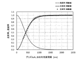
- FIG. 2 is a diagram showing a change in reflection / transmittance with respect to the distance [nm] between the opposing surfaces of the prisms A and B.
- FIG. 3 is a diagram showing the relationship between the transmittance and the incident angle ⁇ in with respect to the spacing [nm] between the opposing surfaces of the prisms A and B.
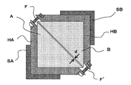
- FIG. 4 is a plan view of the alignment of the opposing surfaces of the prisms A and B using the holding device according to the first embodiment.
- FIG. 5 is a side view as seen from the direction along the facing surface in the alignment of the facing surfaces of the prisms A and B using the holding device according to the first embodiment.
- FIG. 1 is a diagram showing the basic principle of reflection / transmittance control using near-field light.
- FIG. 2 is a diagram showing a change in reflection / transmittance with respect to the distance [nm] between the oppos
- FIG. 6 is a diagram showing a mechanism for adjusting the distance d between the facing surfaces and an attenuation measurement system for setting the attenuation of the attenuator 1 to be manufactured based on the present invention.
- FIG. 7 is a diagram illustrating a result of simultaneously measuring the opposing surface interval and the transmission attenuation amount by changing the opposing surface interval d of the prisms A and B by operating the stage SB in the attenuation measurement system of FIG. is there.
- FIG. 8 is a plan view showing a state in which the prisms A and B are fixed with an adhesive in a state in which the distance between the opposed surfaces at which a desired attenuation is obtained is maintained.
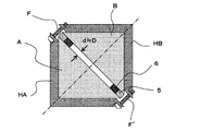
- FIG. 9 shows a state in which a pressing force is applied between the opposing surfaces of the prisms A and B by the adjusting mechanisms F and F ′ included in the L-shaped holding portions HA and HB with a spacer having a thickness D interposed therebetween. It is a figure which shows Example 2 which sets an interval.
- FIG. 10 shows the spatial distribution of the attenuation by the scanning mechanism and the attenuation measurement system while changing the spacer shape by the adjusting mechanisms F and F ′ provided in the holding device with the spacer having the thickness D interposed. It is a figure which shows the modification of Example 2 to measure.
- FIG. 10 shows the spatial distribution of the attenuation by the scanning mechanism and the attenuation measurement system while changing the spacer shape by the adjusting mechanisms F and F ′ provided in the holding device with the spacer having the thickness D interposed. It is a figure which shows the modification of Example 2 to measure.
- FIG. 11 shows that the optical attenuator configured in the first and second embodiments is installed on the rotary stage 8 in the attenuation measurement system, and the stage rotation angle is changed around the vicinity of the near-field light generating part on the opposite surface.
- FIG. 9 is a diagram showing a third embodiment for measuring the distribution of the attenuation amount with respect to the incident angle ⁇ in of the laser.
- FIG. 12 is a diagram illustrating an example of an angular distribution of attenuation measured in the third embodiment.
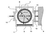
- FIG. 13 shows that the variable optical attenuator constructed in Example 3 is mounted on the light receiving portion of a beam shape measuring device using an image sensor, and the intensity of the laser light to be measured is adjusted to a level suitable for the sensor. It is a figure which shows Example 4 made into.
- FIG. 9 is a diagram showing a third embodiment for measuring the distribution of the attenuation amount with respect to the incident angle ⁇ in of the laser.
- FIG. 12 is a diagram illustrating an example of an angular
- FIG. 14 is a diagram illustrating a fifth embodiment in which a variable optical attenuator is constructed using a polygonal prism.
- FIG. 15 is a diagram illustrating Example 6 in which lenses for correcting the direction of light rays are provided before and after a cylindrical variable optical attenuator including prisms A and B.
- FIG. 16 is a diagram showing a seventh embodiment in which a bearing element 15 having a surface facing the laser optical axis is fixed before and after a columnar variable optical attenuator composed of prisms A and B.
- FIG. 17 is a diagram showing an eighth embodiment in which the optical attenuator constructed in the first to third embodiments is applied as a beam sampling element for output monitoring of a laser oscillator.
- the first embodiment manufactures a transmission type optical attenuator that can be applied to a high-power laser having a wavelength of 1.1 ⁇ m that is widely used in industrial applications such as processing.
- FIG. 4 is a plan view in the alignment of the prisms A and B
- FIG. 5 is a side view from the direction along the facing surface.
- right-angle prisms of the same shape are used as the prisms A and B, and the surfaces (bottom surfaces) of the prisms A and B forming the hypotenuse in FIG.
- the generation surface and the coupling surface are used.
- the holding device When performing alignment, first, the opposing surfaces of the prisms A and B are brought into close contact with each other by a holding device that holds the prisms outside the opposing surfaces.
- the holding device includes a pair of upper and lower L-shaped holding portions HA and HB that hold the prisms A and B along the shape of the apex and leg surfaces toward the opposing surface, and the L-shaped holding portion HA.
- the upper and lower sides of the HB are constituted by screw parts F and F ′ that are screwed to both ends facing each other, and function as a detachable / adjustable fastening mechanism.
- the prisms A and B in which the alignment is optimized as described above are respectively installed on the stages SA and SB which are adjustment mechanisms.
- the stages SA and SB need not be aligned at this time, and the gaps generated between the respective stages and the prisms when the prisms A and B are installed are as shown in FIG. It supplements by forming the filling layer S.
- an appropriate amount of uncured gel adhesive for forming the filling layer S is applied to the fixed surfaces of the stages SA and SB, and then the L-shaped holding portions HA and HB are used to adhere the opposing surfaces of the prisms A and B to each other.
- prism A is placed on stage SA
- prism B is placed on stage SB.
- the prisms A and B are fixed on the stages SA and SB, respectively, and then the alignment of the stages SA and SB is adjusted and optimized. Even if it takes skill and time and is performed automatically, high-cost equipment such as a multi-axis stage, an actuator, a computer for controlling them, and an optimization program are indispensable.
- high-cost equipment such as a multi-axis stage, an actuator, a computer for controlling them, and an optimization program are indispensable.
- the opposing surfaces of the prisms A and B are brought into close contact with each other using the L-shaped holding portions HA and HB as described above. By doing so, a state in which the alignment is arranged is created.
- the stage SB that is the adjusting mechanism is translated with reference to this state, whereby the facing surface distance d of the prisms A and B is It is possible to change while maintaining high parallelism.
- the prism B side when adjusting the reflectance to the prism A and the transmittance to the prism B, the optical axis of the beam emitted by reflection or transmission can be kept constant, and at the same time The accuracy of the attenuation measurement to be performed is improved.
- right-angle prisms of the same shape are used as the prisms A and B.
- other types of prisms and prisms of different sizes may be used, and various opposing surfaces of each prism may be selected. May be.
- a clay-like material that plastically deforms along the shape of the gap between the prisms A and B and the stages SA and SB is used as the filling layer.
- a method may be used in which an external force is applied by a jig and fixed.
- FIG. 6 shows an adjustment mechanism that adjusts the distance d between the opposing surfaces of the attenuator 1 to be manufactured based on the present invention, a laser light source (attenuation amount measuring laser) for measuring the attenuation amount, and an optical sensor.
- Fig. 2 shows a plan view of the system.
- An attenuation measurement laser La is incident from the prism A at an angle ⁇ a that is equal to or greater than the critical angle of the opposing surface (the opposing surface incident angle of the attenuation measurement laser), and is totally reflected on the opposing surface of the prism A, and near-field light is reflected. generate.
- a part of the near-field light that has reached the opposing surface of the prism B, which is set to the predetermined distance d between the opposing surfaces of the prism A is converted into propagating light, passes through the opposing surface, and exits from the prism B.
- the output of the transmitted light emitted from the prism B is detected using the optical sensor Ka.
- the optical sensor Ka is used as the linearity of the sensitivity is secured between the output level of the P in and P t.
- some photoelectric sensors can obtain good linearity on the order of 10 5 or more at a light intensity level that does not saturate, but by combining a plurality of sensors, linearity is ensured in a wider range. It is also possible.
- the arithmetic device 2 calculates an attenuation amount based on the input signal of the optical sensor Ka, outputs a control signal for the actuator drive circuit 3 based on the difference from the target value, and the attenuation amount is transmitted via the actuator 4.
- the position of the stage SB is feedback controlled so as to reach the target value.
- the actuator 4 a piezoelectric actuator or the like capable of highly accurate positioning is suitable.
- the stage SB when the amount of attenuation calculated by the arithmetic unit 2 exceeds the target value, the stage SB is set so as to increase the coupling amount of the near-field light, that is, in the direction of decreasing the facing surface distance d of the prisms A and B. To operate. On the other hand, when the value falls below the target value, the stage SB is operated so as to reduce the coupling amount of near-field light, that is, in the direction of increasing the facing surface distance d.
- a HeNe laser is made incident on the facing surface of the prism A at an angle lower than the critical angle in a form of being superimposed on the spot on the facing surface of the attenuation measuring laser La,
- An interference signal due to mutual reflection between the opposing surfaces of the prisms A and B is detected by the optical sensor Kb.
- ⁇ b is the facing surface incident angle of the facing surface distance measuring laser Lb.
- FIG. 7 shows the results of measuring the distance between the opposed surfaces and the transmission attenuation amount by operating the stage SB and changing the distance between the opposed surfaces of the prisms A and B.
- solid lines indicate theoretical reflectance and transmittance
- dotted lines indicate experimental values of interference signals
- plots indicate measured values of transmittance.
- the attenuation measurement laser La and the opposed surface distance measurement laser Lb a YAG laser and a HeNe laser with a wavelength of 1.1 ⁇ m and a random polarization output of 10 W are used, respectively, and Ge optical sensors are used for the optical sensors Ka and Kb, respectively. Type sensor and Si photoelectric sensor are used.
- the attenuation can be adjusted with high accuracy by adjusting the distance d between the opposing surfaces while monitoring the transmission attenuation in real time and controlling the stage SB to a position where the target attenuation can be obtained.
- the change gradient of the signal obtained by the optical sensor Ka with respect to the distance becomes slow, and the S / N also decreases, so that highly accurate positioning control of SB may be difficult.
- the optical path that passes through the prisms A and B such as the outer peripheral portion of the opposing surface as shown in FIG. 8, with the stage SB held at a fixed position with the opposing surface interval d that provides a desired attenuation.
- the adhesive 5 is applied and cured at a position where it is not blocked.
- an epoxy system that can ensure sufficient mechanical fastness and an optical adhesive with high transparency are suitable.
- the reach distance of near-field light also depends on the refractive index n 2 between the opposing surfaces, as shown in the above formula. This means that the amount of attenuation changes due to environmental factors such as changes in humidity and dust. Therefore, by sealing the outer periphery of the opposing surface with a vacuum adhesive or the like while the space between the opposing surfaces is filled with an inert gas such as nitrogen gas, stability against environmental fluctuations is given and practicality is improved. Can do.
- the stage SB is operated by the actuator 4, but the movement amount of the stage SB may be manually adjusted by a screw mechanism or the like based on the signals of the optical sensors Ka and Kb.
- the second embodiment uses an adjusting mechanism provided in the holding device and presses them together with a spacer that sets a predetermined spacing between the opposing surfaces of the prisms A and B interposed.
- a spacer that sets a predetermined spacing between the opposing surfaces of the prisms A and B interposed.
- FIG. 9 shows a plan view.
- the spacer 6 having a thickness D is disposed so as to be sandwiched in a position where the laser light path between the opposing surfaces of the prisms A and B is not blocked, and the prisms A and B are respectively L-shaped holding units having the same structure as in the first embodiment.
- the prisms A and B are operated by operating the screw parts F and F ′ as adjustment mechanisms provided between the L-shaped holding portions HA and HB in the state of being accommodated in the HA and HB, as in the first embodiment.
- a pressing force is applied between the opposing surfaces to create a close contact state between the opposing surface and the spacer.
- the spacer 6 when a material having high rigidity that can ignore a change in thickness even by the maximum tightening torque of the screw components F and F ′ is used as the spacer 6, the screw components F and F ′ are tightened with a predetermined tightening torque.
- the distance d between the opposing surfaces of the prisms A and B can be set uniformly by the thickness D of the spacer 6.
- the spacer 6 when a material capable of adjusting the thickness D by elastic deformation or plastic deformation by the torque of the screw parts F and F ′ is used as the spacer 6, The surface distance d can be adjusted. That is, in a region where the pressing force is sufficiently small, the facing surface distance d is set by the thickness D of the spacer. On the other hand, by increasing the pressing force and elastically deforming or plastically deforming the spacer material, the facing surface interval d can be gradually reduced from the initial D and set to an arbitrary value. Manufacturing that performs adjustment and measurement of attenuation at the same time as in Example 1 by providing a space through which laser light passes in the parts of the L-shaped holding portions HA and HB and applying the attenuation measurement system shown in FIG.
- the device is being constructed.
- the screw parts F and F ′ are provided with appropriate play between the L-shaped holding parts HA and HB in contact with the leg surfaces of the prisms A and B and the screw parts F and F ′ constituting the adjustment mechanism.
- the facing surface distance d is adjusted, the lateral force acting on the facing surfaces of the prisms A and B other than the normal direction is released, and the pressing force can be finely adjusted.
- the uniformity of the spacer dimensions is the key to always obtain a constant attenuation regardless of the incident position of light. Therefore, as the spacer, a foil-like metal or a polymer particle size standard fine particle having a diameter value given with high accuracy may be disposed between the opposing surfaces.
- a thin film may be formed in advance by a sputtering method, a vapor deposition method, a spin coating method, or the like at a position that does not block the optical path of the prism facing surface.
- these film-forming methods are very effective for setting the distance between the opposing surfaces with high accuracy because it is easy to produce a desired film thickness on the order of nanometers.
- the screw parts F and F ′ constituting the adjusting mechanism between the L-shaped holding portions HA and HB are a total of four places (screw parts F and F shown in FIG. F ′ and the back side of each).
- the spacer 6 is formed of a material that can be elastically deformed or plastically deformed by the torque of the screw parts F and F ′ to adjust the thickness D, the fastening force at each position is adjusted independently, thereby It is also possible to give a distribution to the distance d. In other words, it is possible to distribute the attenuation evenly by balancing the four locations, or to intentionally disrupt this uniformity and to provide a distribution in which the attenuation value varies depending on the location where the light is transmitted. It is.
- the scanning mechanism 7 is provided in the attenuation measurement system as shown in FIG.
- the prisms A and B fixed to a pedestal having a reference surface for laser light along the opposing surfaces, the incident position of the laser light on the attenuator is changed, and the attenuation amount for each place is changed.
- Measure with sensor Ka In order to measure at a higher speed, an image sensor having a size capable of receiving the measurement beam is incident on the optical sensor Ka while the measurement beam La expanded to a thickness covering the inspection target region is incident instead of the scanning mechanism 7. (CCD, CMOS camera, etc.) are used.
- multipoint simultaneous measurement of attenuation can be performed at low cost and at high speed only by taking a single image without using the scanning mechanism 7.
- a variable optical attenuator that adjusts the attenuation by changing the laser incident position with respect to the reference plane.
- the attenuation amount is measured while adjusting the tightening force of the screw parts F and F ′ as the adjusting mechanism, and when the desired attenuation amount and its distribution are obtained, the same as in the first embodiment.
- the outer peripheral part of the opposing surface is fixed with an adhesive 5 or the like. Thereafter, the L-shaped holding portions HA and HB are removed to complete the laser light attenuator.
- the fastening force of the screw components F and F ′ may be automatically adjusted by rotationally driving using a motor having a desired positioning accuracy, F ′ may be manually adjusted by a driver or the like.
- the laser light attenuator composed of the prisms A and B whose spacing between the opposing surfaces is determined in advance according to the first or second embodiment is fixed to a pedestal having a reference surface for the laser light, and the pedestal is rotated.
- a laser beam attenuator with a variable attenuation amount is constructed.
- an aluminum foil having a thickness of 0.8 ⁇ m was used as a spacer, and the distance d between the opposing surfaces of the prisms A and B was maintained in parallel.
- the transmission attenuation is set to 0.2%, and is placed on the rotation stage 8 as a rotation adjusting mechanism installed in the attenuation measurement system, and is set with respect to the laser incident angle.
- the attenuation distribution is measured.
- the rotary stage 8 has a reference surface with respect to the incident direction of the laser beam to be attenuated, and the incident angle with respect to the prisms A and B can be adjusted by rotating the reference surface.
- the graph shown in FIG. 12 is obtained when the angle of incidence perpendicular to the laser incident leg surface of the prism A is 0 ° (reference angle) and the rotation angle ⁇ of the rotary stage 8 is operated within a range of ⁇ 15 °.
- the experimental data of the transmission attenuation amount is shown.
- An attenuation of 0.20% is obtained at a rotation angle of 0 ° (incident angle to the opposing surface is 45 °), and an angle smaller than around -7 ° is less than the critical angle and a transmittance of almost 100% is obtained. .
- By operating the rotary stage 8 with a rotation angle of 0 ° as a reference it is possible to obtain attenuation in a range of up to 10 3 with a rotation angle of ⁇ 5 °, with 12% at -5 ° and at + 5 ° An attenuation of 0.01% can be obtained with good reproducibility.
- the actuator 4 of the rotary stage 8 When the actuator 4 of the rotary stage 8 is manually operated, it uses a micrometer or the like while incorporating a return spring to eliminate backlash, and when automated, an angle control mechanism combined with a rotary encoder or the like is used. Set the angle to accuracy.
- this optical attenuator place the optical attenuator whose angle characteristic of attenuation was measured in advance by the above procedure at an angle that provides the reference attenuation with respect to the laser optical axis.
- the desired amount of attenuation can be obtained by operating the actuator 4 in accordance with the angle characteristic map of the amount of attenuation created in advance as shown in FIG.
- the prism whose spacing between the facing surfaces is determined according to the second embodiment is used, but a prism whose spacing between the facing surfaces is determined according to the first embodiment may be used.
- a variable optical attenuator constructed based on the third embodiment is installed in the light receiving portion of a beam shape measuring device (beam profiler) using a high-sensitivity image sensor such as a CCD or CMOS, and measurement is performed.
- a device that adjusts the intensity of the target laser beam to a level suitable for the sensor has been constructed.
- the beam profiler is used for measuring the beam shape of laser light and ensuring the processing accuracy and safety of treatment, particularly in the field of handling high-intensity laser light such as processing and medical care. When a strong light exceeding the allowable range of the sensor is incident on the type sensor, the measurement accuracy is degraded or damaged.
- variable optical attenuation comprising prisms A and B fixed on the front surface of a measuring device (CCD camera) 9 and a rotary stage 8 is provided.
- a housing 10 in which a vessel is housed is installed, and a high-intensity laser beam incident from the left hand is attenuated to an appropriate level, then emitted in the right-hand direction, and incident on the measuring device 9. Note that when the transmission attenuation light to the prism B is used, the component reflected to the prism A side is scattered at an angle corresponding to the stage rotation angle, and thus it is necessary to safely process this.
- the light absorption structure 11 is provided inside the housing 10 so as to reliably absorb the scattered components.
- it is effective to adopt a forced air cooling method using a water cooling of the housing or a fan in order to cope with heat generation.
- optical measuring instruments such as a beam profiler are provided with a light receiving portion 12 having a shape defined by the standards of each industrial field.
- a light receiving portion 12 having a shape defined by the standards of each industrial field.
- the housing of the variable optical attenuator based on the present embodiment is also provided with this standard shape, so that it can be easily attached to a commercially available beam profiler.
- the high-intensity laser beam is attenuated reliably and with high accuracy by a highly durable variable optical attenuator, and then incident on a high-sensitivity camera, thereby improving the reliability of beam profile measurement.
- the optical attenuator is ideally required not to change other parameters such as the optical axis and beam shape during the attenuation process of incident light.
- the incident angle of light on the prism surface changes with the rotational movement of the prism, so that the light beam is refracted, and the optical axis is slightly shifted before and after the attenuator. May occur.
- an attenuator is constructed with two right-angle prisms with a side of 25 mm
- an optical axis shift of ⁇ 0.7 mm occurs within an angle range of ⁇ 5 °.
- the light strikes the edge of the light receiving portion of the measuring device due to the adjustment of the attenuation amount, and inadvertent stray light is generated, causing a measurement error.
- prisms A and B are obtained by dividing a regular dodecagonal column into two diagonal lines. Thereby, the incident angle and the emission angle of the laser beam at the refractive index boundary surface of the prism surface are reset every 30 ° of the stage rotation angle and return to 0 °.
- the distance between the opposing surfaces is fixed in the same manner as in the first to third embodiments, thereby realizing an ideal variable attenuator in which the optical axis does not shift before and after attenuation and only the transmittance changes.
- the attenuation value obtained without shifting the optical axis changes stepwise.
- the light beam component that does not pass through the cylindrical axis is refracted by the convex surface of the surface of the prism A and is opposed to the opposite surface. Distribution occurs in the incident angle of the light beam that reaches. This is because the transmittance decreases as the incident angle increases, and the beam profile changes before and after attenuation. Therefore, assuming refraction on the surface of the prism A, it is preferable to install the lens structure 13 that corrects this refraction before entering the prism A so that the incident angles of the light components entering the opposing surface from the prism A are made uniform. is there.
- an ideal variable attenuator is realized by preventing the shift of the optical axis and the change of the beam profile before and after attenuation by installing the correction lens 14. Yes.
- the prisms A and B have a single axially symmetric cylindrical shape.
- a spherical attenuator is constructed using a hemispherical prism, and the pitch angle, yaw angle, and roll angle are set using a spherical motor or the like. It is good also as a form controlled independently.
- Example 7 the correction lens of Example 6 is made unnecessary by eliminating the cause of the occurrence of optical axis deviation and transmitted beam distortion. That is, as shown in FIG. 16, a transparent bearing element 15 having a surface facing the laser optical axis is disposed before and after a cylindrical variable attenuator composed of prisms A and B. The bearing element is fixed, and the cylindrical attenuator rotates through the buffer layer 16 on the inner side.
- the buffer layer 16 is made of an optical oil such as a microscope immersion oil, and the refractive index of the bearing element and the attenuator surface is matched and optically integrated. Take a role.
- the surface of the bearing element on which the laser beam is incident and emitted even when the cylindrical attenuator rotates is always kept in a direct alignment with the laser optical axis, so that the optical axis is shifted before and after transmission.
- an ideal variable optical attenuator with no distortion of beam shape is always kept in a direct alignment with the laser optical axis, so that the optical axis is shifted before and after transmission.
- the eighth embodiment shows an example in which the optical attenuator manufactured according to the previous embodiments is used as a beam sampling element and is applied to an output monitoring system in order to feedback control the oscillation output in the high-power laser apparatus. .
- a beam sampler made of a glass substrate or a dielectric multilayer film substrate is used in the output monitor of a laser oscillator.
- the monitor optical sensor in the subsequent stage is not suitable. Monitoring is performed to compensate for the shortage of attenuation by using thermal sensors that emphasize laser durability, or by using multiple sampling elements to make multiple stages and combine them.
- the former is in terms of the S / N and non-linearity of the sensor, and the latter is a situation where it is difficult to improve the accuracy of monitoring due to stray light and an increase in error factors due to the large size and complexity of the optical system.
- the optical attenuators of Embodiments 1 to 7 are arranged in the optical path of the laser light output from the laser oscillator 17 to be controlled, so Incident light is branched into a reflection component to the prism A and transmitted light to the prism B with a high branching ratio, and the transmission attenuated light to the prism B is measured by the optical sensor 18 capable of detecting at high speed and with high sensitivity. Yes.
- the monitor signal detected by the optical sensor 18 is sent to the arithmetic unit 2, and after comparison with the target value, it is fed back to the oscillation control circuit 19 for laser light, and the laser output Pout is directed toward the target value. Control to converge.
- an optical attenuator that can obtain a predetermined attenuation amount using prisms A and B obtained by dividing a regular hexagonal cylinder into two equal parts is used, and the incident / exit interface is optically optimized while optimizing the incident angle of the opposing surface.
- a prism shape that faces the axis, a beam sampler that achieves ideal attenuation characteristics for the laser light to be controlled is realized.
- the attenuation can be optimized according to the sensitivity characteristics of the monitoring optical sensor, and at the same time, the attenuation can be stably maintained even for a high-intensity laser beam.
- a simple laser light output monitoring system can be constructed at low cost.
- the first and second embodiments it is possible to control and manage the laser irradiation amount in a traceable manner by using a monitor optical sensor whose sensitivity is calibrated while setting the attenuation amount with high accuracy. it can. If this is applied to a laser processing apparatus, it becomes possible to highly control the laser irradiation method in accordance with the processing content and to precisely control the processing quality.
- both high accuracy and simplification of the multi-axis alignment work between the opposing surfaces of the prism can be achieved at the same time, and at the same time, the amount of attenuation can be measured in real time to achieve a desired value. Because it is possible to adjust the accuracy, it is possible to realize a light transmission type near-field optical coupling type optical attenuator that can obtain high proof strength even for high-power lasers at low cost. It can be expected to be applied in a wide range of fields, including attenuation of high-power lasers.
- A, B Prism SA, SB: Stage ⁇ in : Opposing surface incident angle d: Opposite surface spacing P in : Incident light output (attenuation measurement laser) P t : Transmitted light output (attenuation measurement laser) ⁇ a: Opposing surface incident angle (attenuation measurement laser) ⁇ b: facing surface incident angle (facing surface spacing laser) Ka: Optical sensor (for attenuation measurement) Kb: Optical sensor (for measuring the distance between opposing surfaces) D: Spacer thickness HA, HB: L-shaped holding part F: Fastening mechanism 1: Laser light attenuator according to the present invention 2: Arithmetic device 3: Actuator drive circuit 4: Actuator 5: Adhesive 6: Spacer 7: Scanning mechanism 8: Rotating stage 9: Optical measuring device 10: Housing 11: Light absorption part 12: Connection mount part 13: Correction lens (incident side) 14: Correction lens (outgoing side) 15: Bearing element 16: Buffer layer 17: Laser oscil
Landscapes
- Physics & Mathematics (AREA)
- Optics & Photonics (AREA)
- General Physics & Mathematics (AREA)
- Electromagnetism (AREA)
- Engineering & Computer Science (AREA)
- Plasma & Fusion (AREA)
- Mechanical Light Control Or Optical Switches (AREA)
- Optical Elements Other Than Lenses (AREA)
Abstract
レーザ光減衰装置を製造するための製造装置は、2つのプリズムA、Bの対向面を直接あるいは所定の厚さを有するスペーサを介して互いに押圧させることで対向面間隔を初期設定する保持装置(L型保持部HA、HB)と、この初期設定状態を基準として、プリズムA、Bの対向面での近接場光の発生と結合によって、プリズムAに入射される光出力に対し、プリズムA、Bのいずれか一方を出射する光出力の比率を調整する調整機構(アクチュエータ4)と、光出力の比率を測定する減衰量計測システムとから構成されている。これにより、耐久性、実用性に優れた減衰量可変の光減衰器を低コストに実現することができる。
Description
本発明は、所望の減衰量に設定可能なレーザ光減衰器の製造装置、この製造装置により製造されたレーザ光減衰器及びこのレーザ光減衰器の製造方法に関する。
レーザ光は、加工装置、計測装置、医療機器などの分野で広く活用されており、性能向上や安全確保のため、レーザ光の出力(パワー・エネルギ)、空間的プロファイル(レーザ光の断面形状、広がり角)、時間的プロファイル(パルス幅、繰り返し波形、波長)を正確に測定することが不可欠である。たとえば、レーザ加工装置や医療機器において、集光点のビームプロファイルの乱れは、加工不良の発生や医療事故の原因となるため、高精度な計測が求められる。同様に、工場の製造ラインで連続運転されるレーザ加工装置では、レーザ発振出力の時間的な変動が、製品のばらつきや品質低下に直結するため、レーザ出力を正確にモニタすることが求められる。
一般に、光の出力や、空間・時間的プロファイルを高精度に計測する装置には、フォトダイオードやCCD等の光電型の光センサが使用されている。光電型の光センサは、感度が高く、しかも小型で高速である一方、高強度な光が入射した場合、センサが飽和して正しい測定が困難となるばかりでなく、センサの損傷等を招き、故障の原因となる場合もある。
そのため、高強度なレーザ光が搭載された加工装置などでは、減光フィルタ等の光減衰器を用いてレーザ光の強度を十分に減衰させた後、計測装置に入射させることで、加工点のレーザスポット形状の測定や出力変動のモニタリングを行っている。
このような高強度なレーザ光を測定する場合、光減衰器の選定が重要となる。減衰原理が不適切な場合、減衰器自体の破損を招くばかりでなく、減衰量が不足していると後段の計測装置の焼損や事故を招くことになる。一方、減衰量が過大であると、S/Nが低下し、測定誤差の要因となる。
そのため、高強度なレーザ光が搭載された加工装置などでは、減光フィルタ等の光減衰器を用いてレーザ光の強度を十分に減衰させた後、計測装置に入射させることで、加工点のレーザスポット形状の測定や出力変動のモニタリングを行っている。
このような高強度なレーザ光を測定する場合、光減衰器の選定が重要となる。減衰原理が不適切な場合、減衰器自体の破損を招くばかりでなく、減衰量が不足していると後段の計測装置の焼損や事故を招くことになる。一方、減衰量が過大であると、S/Nが低下し、測定誤差の要因となる。
従来より、光減衰器として、基板内に目的の波長を吸収する物質を分散させて透過の過程で光強度を徐々に落とす吸収型、基板と周囲媒質の屈折率差や基板表面の薄膜等を利用する反射・透過型、さらに、特定の偏光方位の光のみを選択的に分離する偏光型などが存在する。
しかし、これらの光減衰器は、いずれも高強度なレーザ光の減衰に対応することができない。たとえば、吸収型や偏光型は光学素子の耐久性が低く、高強度なレーザ光が入射すると容易に破損したり、発熱によるレンズ効果によってビーム形状に歪が生じる。
しかし、これらの光減衰器は、いずれも高強度なレーザ光の減衰に対応することができない。たとえば、吸収型や偏光型は光学素子の耐久性が低く、高強度なレーザ光が入射すると容易に破損したり、発熱によるレンズ効果によってビーム形状に歪が生じる。
また、反射・透過型は耐久性については期待できるものの、一つの素子で得られる減衰量が高々数%から0.01%程度にすぎず、高強度のレーザ光を減衰させるには、複数の素子を直列に並べて段階的に光強度を減衰させることになる。そのため、減衰光学系の大型化や多重反射による迷光の発生、光軸のずれ等が避けられず、これらの減衰器を介したレーザ光の測定では信頼性を確保することが困難であった。
このような背景から、コンパクトなサイズで、高強度のレーザ光に対しても適用可能な耐久性を持ち、減衰量を高精度に設定可能な可変型の光減衰器の開発が求められている。
このような背景から、コンパクトなサイズで、高強度のレーザ光に対しても適用可能な耐久性を持ち、減衰量を高精度に設定可能な可変型の光減衰器の開発が求められている。
ところで、光学素子が高強度なレーザ光に対して耐久性を発揮させるためには、素子内部で光エネルギを吸収しない透明な材料を用いればよく、このような材料で光減衰器を構築する手段として、近接場光(エバネッセント光)の結合効果を利用する技術が知られている。
特許文献1には、ビームスプリッタからモニタ光を光検出器で検出し、レーザ出力を安定化させることが記載されている。
特許文献2には、凸レンズと直角プリズムとの間でエバネッセント光を発生させ、凸レンズの凸面形状に応じたレーザ強度分布を得ることが記載されている。
非特許文献1には、波長が数センチメートルの電波領域において、エバネッセント波(光)の発生・結合により透過率と反射率を可変させることが記載されている。
非特許文献2には、波長10.6μmの赤外線領域において、エバネッセント波の発生・結合によって生じた減衰量を、アクチュエータを用いて可変させることが記載されている。
特許文献2には、凸レンズと直角プリズムとの間でエバネッセント光を発生させ、凸レンズの凸面形状に応じたレーザ強度分布を得ることが記載されている。
非特許文献1には、波長が数センチメートルの電波領域において、エバネッセント波(光)の発生・結合により透過率と反射率を可変させることが記載されている。
非特許文献2には、波長10.6μmの赤外線領域において、エバネッセント波の発生・結合によって生じた減衰量を、アクチュエータを用いて可変させることが記載されている。
J.J. Brady, et al., "Penetration of Microwaves into the Rarer Medium in Toral Reflection", J. Opt. Soc. Am, Vol.50, No.11, pp.1080-1084, 1960.
K. Wilner, and N.P. Murarka, "Design considerations and test result of an evanescent switch-attenuator", Appl. Opt., Vol.20, No.20, pp.3600-3604, 1981.
近接場光の結合特性を利用した光の減衰について、図1を用いて説明する。
プリズムAの外部から斜面に対し全反射となる角度で光(Pin)を入射すると、斜面の外側には近接場光(エバネッセント光)が発生する。この近接場光は、斜面(近接場光の発生面)近傍から波長程度の範囲に局在し、発生面の法線方向へは伝搬しない性質を持っている。
近接場光の強度はプリズムAの発生面の表面で最も大きく、発生面からの距離に従って指数関数的に減衰する。ここで近接場光の到達距離(浸み出し長)dpは、光の波長をλ、プリズムの屈折率をn1、周囲の屈折率をn2、プリズム斜面へのレーザ光の入射角をθinとすると、次式で与えられる。
dp=λ/2π/(n1 2・sin2θin-n2 2)1/2
プリズムAの外部から斜面に対し全反射となる角度で光(Pin)を入射すると、斜面の外側には近接場光(エバネッセント光)が発生する。この近接場光は、斜面(近接場光の発生面)近傍から波長程度の範囲に局在し、発生面の法線方向へは伝搬しない性質を持っている。
近接場光の強度はプリズムAの発生面の表面で最も大きく、発生面からの距離に従って指数関数的に減衰する。ここで近接場光の到達距離(浸み出し長)dpは、光の波長をλ、プリズムの屈折率をn1、周囲の屈折率をn2、プリズム斜面へのレーザ光の入射角をθinとすると、次式で与えられる。
dp=λ/2π/(n1 2・sin2θin-n2 2)1/2
ところで、近接場光の存在する領域に光を散乱させる物体を近づけると、近接場光は物体に結合し、局在性を失って空間を伝搬するようになる。この空間伝搬光の強度は、散乱体の位置における近接場光の強度に依存する。このときプリズムA内に反射する光の出力は、入射光の出力からこの伝搬光の出力を差し引いた値となる。すなわち、プリズム材料の光吸収が無視できる場合、入射光の出力をPin、反射光の出力をPr、散乱された伝搬光(透過光)の出力をPtとすると、次の関係が成り立つ。
Pin=Pr+Pt
散乱体としてプリズムBを導入し、その斜面を結合面とすると、プリズムAへの入射光の出力Pinを、プリズムAから出射される反射光出力Prと、プリズムBへの透過光出力Ptに分岐する光分配器(ビームスプリッタ)が形成される。
Pin=Pr+Pt
散乱体としてプリズムBを導入し、その斜面を結合面とすると、プリズムAへの入射光の出力Pinを、プリズムAから出射される反射光出力Prと、プリズムBへの透過光出力Ptに分岐する光分配器(ビームスプリッタ)が形成される。
近接場光を発生、結合させるプリズムA、Bの斜面を、一対の「対向面」と呼ぶこととすると、対向面間の間隔や、プリズムA内部から対向面に入射する光の入射角θinを変化させることで、プリズムA、Bの対向面における反射減衰量及び透過減衰量を、原理的にはそれぞれ100%~0%及び0%~100%の間で調整可能である。
図2は、プリズムA、Bを光学ガラスBK7からなる直角プリズムとし、レーザ波長1.1μmとした場合において、プリズムA、Bの対向面間隔[nm]に対する反射率及び透過率の変化を示すもので、線は理論値(実線は反射率の理論値、破線は透過率の理論値)〇のプロットは実験値を示す。なお、実験では、入射角θinを45°に設定している。
一方、図3は、プリズムAの斜面への入射角(図1のθin)の調整によって近接場光の浸み出し長を変化させた場合の、プリズムA、Bの対向面間隔[nm]に対する透過率の変化(実線、破線など各種の線は理論値、〇のプロットは実験値)を示す。
一方、図3は、プリズムAの斜面への入射角(図1のθin)の調整によって近接場光の浸み出し長を変化させた場合の、プリズムA、Bの対向面間隔[nm]に対する透過率の変化(実線、破線など各種の線は理論値、〇のプロットは実験値)を示す。
しかし、この近接場光の結合効果を利用するには、全反射による近接場光発生面と、その近傍の近接場光結合面との間隙を、波長オーダの精度で多軸アライメントする必要がある。このため、この原理を用いた減衰器は、先行技術文献に代表されるように、波長が比較的長く、アライメント精度が要求されない電波や中赤外線を対象とするものに限られていた。
一方、産業需要の高い可視~近赤外線領域に適用するには、ナノメートルオーダのアライメント精度が不可欠で、熟練者の高度な調整技能や、自動で行う場合もセンサや多軸アクチュエータ機構及びそれらの最適化演算などが求められ、多大なコストを要することから、これまで実用化の障壁となっていた。
一方、産業需要の高い可視~近赤外線領域に適用するには、ナノメートルオーダのアライメント精度が不可欠で、熟練者の高度な調整技能や、自動で行う場合もセンサや多軸アクチュエータ機構及びそれらの最適化演算などが求められ、多大なコストを要することから、これまで実用化の障壁となっていた。
加えて、近接場光の結合効果を利用した減衰器の減衰量は、原理的に、アライメントが整った後で、初めて対向面の間隔や角度で決定づけられる量であるため、アライメント自体が困難であった従来の状況の下では、その減衰量を所望の値に制御することや、減衰量を自在にかつ高精度に設定することは、技術的に不可能であった。
そこで、本発明の目的は、近接場光の発生面と結合面における多軸アライメント作業を、精度を維持したまま簡略化するとともに、減衰量の計測・調整を高精度に行うことによって、高強度レーザにも適用可能な耐久性を備え、可視~近赤外波長域で機能させることができる、実用性に優れた減衰量可変の光減衰器を低コストに実現することにある。
上記の課題を解決するため、本発明によるレーザ光減衰器の製造装置は、2つのプリズムA、Bの対向面を直接あるいは所定の厚さを有するスペーサを介して互いに押圧させ、対向面間隔を最小化することでアライメントを初期設定する保持装置と、この初期設定状態を基準として、プリズムA、Bの対向面での近接場光の発生と結合によって、プリズムAに入射される光出力に対し、プリズムA、Bのいずれか一方を出射する光出力の比率を調整する調整機構と、この光出力の比率を測定する計測システムとからなり、比率の測定結果に応じて対向面間隔を調整機構により調整し、所望の減衰量を得られるようにした。
また、本発明によるレーザ光減衰器は、上記の製造装置における調整機構により、光出力の比率が調整された状態で、プリズムA、Bが固定されたもので構成されている。
本発明によるレーザ光減衰器の製造方法は、2つのプリズムA、Bの対向面を直接あるいは所定の厚さを有するスペーサを介して互いに押圧させることで対向面間隔を最小化し、アライメントの初期状態を設定する第1の工程と、初期設定状態を基準として、プリズムA、Bの対向面での近接場光の発生と結合によって、プリズムAに入射される光出力に対し、プリズムA、Bのいずれか一方を出射する光出力の比率を調整する第2の工程と、光出力の比率を測定する第3の工程と、比率の測定値に基づいて調整機構を作動させ、光出力の比率が目標値となった状態で、プリズムA、Bを互いに固定する第4の工程とから構成されている。
本発明によれば、プリズムの対向面間の多軸アライメント作業の高精度化と簡略化を両立させると同時に、アライメント中、リアルタイムに計測した減衰量が所望の値となるように高精度に調整可能とすることで、近接場光結合型で、減衰量を所望の値に設定可能な光減衰器を低コストに実現することが可能となる。
[実施例1]
実施例1は、例えば、加工等の産業用途で多く普及する波長1.1μmの高出力レーザにも適用し得る透過型光減衰器を製造するものである。
まず、プリズムA、Bのアライメントについて、図面を用いて説明する。
図4はプリズムA、Bのアライメントにおける平面図、図5は対向面に沿った方向からの側面図を示している。なお、この実施例では、プリズムA、Bとして、同形状の直角プリズムを用い、図4において斜辺を形成するプリズムA、Bの面(底面)を互いに対向させて配置し、それぞれ近接場光の発生面及び結合面としている。
実施例1は、例えば、加工等の産業用途で多く普及する波長1.1μmの高出力レーザにも適用し得る透過型光減衰器を製造するものである。
まず、プリズムA、Bのアライメントについて、図面を用いて説明する。
図4はプリズムA、Bのアライメントにおける平面図、図5は対向面に沿った方向からの側面図を示している。なお、この実施例では、プリズムA、Bとして、同形状の直角プリズムを用い、図4において斜辺を形成するプリズムA、Bの面(底面)を互いに対向させて配置し、それぞれ近接場光の発生面及び結合面としている。
アライメントを行う際は、まず、プリズムの対向面外を保持する保持装置により、プリズムA、Bの対向面同士を互いに密着させる。この実施例では、保持装置は、プリズムA、Bの頂角部及び脚面部の形状に沿って対向面に向かって保持する上下一対のL型保持部HA、HBと、このL型保持部HA、HBの上側、下側において互いに対向する両端部に螺合するネジ部品F、F’とで構成され、着脱・調整可能な締結機構として機能する。
すなわち、L型保持部HA、HBをネジ部品F、F’により互いに近接するように引き付けることで、L型保持部HA、HBの内側に保持されたプリズムA、Bの対向面同士を互いに密着させることができる。
この状態は、プリズムAの近接場光発生面とプリズムBの近接場光結合面の間で各軸のアライメントが最適化され、対向面間の距離(以下、「対向面間隔」という。)が最小で、かつ対向面間の平行度が最大の理想的な状態に相当する。これによりプリズムA、Bの対向面間隔d及び両対向面間のなす角度は原理的に零となるが、本発明ではこの状態を、対向面の位置関係を調整するための距離及び角度の原点と位置付け、この操作をアライメントにおける「初期設定」と呼ぶことにする。
すなわち、L型保持部HA、HBをネジ部品F、F’により互いに近接するように引き付けることで、L型保持部HA、HBの内側に保持されたプリズムA、Bの対向面同士を互いに密着させることができる。
この状態は、プリズムAの近接場光発生面とプリズムBの近接場光結合面の間で各軸のアライメントが最適化され、対向面間の距離(以下、「対向面間隔」という。)が最小で、かつ対向面間の平行度が最大の理想的な状態に相当する。これによりプリズムA、Bの対向面間隔d及び両対向面間のなす角度は原理的に零となるが、本発明ではこの状態を、対向面の位置関係を調整するための距離及び角度の原点と位置付け、この操作をアライメントにおける「初期設定」と呼ぶことにする。
次いで、上記のようにアライメントが最適化された状態のプリズムA、Bを、調整機構であるステージSA、SBにそれぞれ設置する。本実施例によれば、このときステージSA、SBのアライメントは整っている必要がなく、プリズムA、Bを設置した際に生じる各ステージとプリズムの間に生じる間隙は、図5に示すように充填層Sを形成することで補完する。この実施例では、充填層Sを形成する未硬化のジェル状接着剤を、ステージSA、SBの固定面に適量塗布したのち、L型保持部HA、HBによりプリズムA、Bの対向面の密着を維持した状態のまま、プリズムAをステージSA上に、そして、プリズムBをステージSB上に配置する。この状態で接着剤を硬化させると、プリズムA、Bは、最適なアライメント、すなわち、対向面間隔d≒0かつ両対向面間のなす角度≒0を保った状態でそれぞれステージSA、SB上に固定される。
通常の手順では、ステージSA、SB上にプリズムA、Bをそれぞれ固定したのち、ステージSA、SBのアライメントを調整・最適化していくが、この作業は、人が行う場合、熟練者による高度な技能や時間を要し、自動で行う場合も、多軸ステージやアクチュエータ、それらを制御する計算機や最適化プログラム等の高コストな設備が不可欠である。
これに対し、本実施例では、プリズムA、BをそれぞれステージSA、SBに固定する前段階で、前述のようにL型保持部HA、HBを用いてプリズムA、Bの対向面を密着させることにより、アライメントを整えた状態を作り出しておく。そして、この状態のプリズムA、BとステージSA、SBとの間に残るミスアライメントは、充填層Sによって補完することで、前述したような煩雑で高コストなアライメント技術が不要となる。なおこの実施例では、厳密には、プリズムA、Bを通る光軸とステージの稼働軸の間に若干ずれが生じるおそれがあるが、これは光減衰器の性能に影響するものではない。
これに対し、本実施例では、プリズムA、BをそれぞれステージSA、SBに固定する前段階で、前述のようにL型保持部HA、HBを用いてプリズムA、Bの対向面を密着させることにより、アライメントを整えた状態を作り出しておく。そして、この状態のプリズムA、BとステージSA、SBとの間に残るミスアライメントは、充填層Sによって補完することで、前述したような煩雑で高コストなアライメント技術が不要となる。なおこの実施例では、厳密には、プリズムA、Bを通る光軸とステージの稼働軸の間に若干ずれが生じるおそれがあるが、これは光減衰器の性能に影響するものではない。
充填層としての接着剤が硬化した後、L型保持部HA、HBを取り外し、この状態を基準として調整機構であるステージSBを並進運動させることで、プリズムA、Bの対向面間隔dを、高い平行度を維持したまま変化させることが可能である。特に、プリズムB側を移働させることで、プリズムAへの反射率及びプリズムBへの透過率を調整する際、反射もしくは透過により出射するビームの光軸を一定に維持することができ、同時に行う減衰量測定の精度が向上する。
なお、この実施例では、プリズムA、Bとして同形状の直角プリズムを採用しているが、他の形態のプリズムや大小異なるプリズムを採用してもよいし、さらに各プリズムの対向面を種々選択してもよい。
また、充填層の材料としては、上記未硬化の接着剤の他、プリズムA、BとステージSA、SBの隙間の形状に沿うように塑性変形する粘土状の材料を充填層として用い、それらを介して治具により外力を加えて固定する方式でもよい。
また、充填層の材料としては、上記未硬化の接着剤の他、プリズムA、BとステージSA、SBの隙間の形状に沿うように塑性変形する粘土状の材料を充填層として用い、それらを介して治具により外力を加えて固定する方式でもよい。
次に、プリズムA、Bの対向面間隔dを調整し、減衰量を設定するための減衰量計測システムについて、図面を用いて説明する。
図6は、本発明に基づいて作製しようとする減衰器1の対向面間隔dを調整する調整機構と、減衰量を測定するためのレーザ光源(減衰量測定用レーザ)と光センサからなる計測システムの平面図を示している。プリズムAから、対向面の臨界角以上の角度θa(減衰量測定レーザの対向面入射角度)で減衰量測定用のレーザLaを入射し、プリズムAの対向面において全反射させ、近接場光を発生させる。
ここで、プリズムAに対し所定の対向面間隔dに設定されたプリズムBの対向面に到達した近接場光の一部は伝搬光に変換され、対向面を透過して、プリズムBから出射する。ここでは、この透過光を対象に減衰量を設定するため、プリズムBから出射した透過光の出力を光センサKaを用いて検出している。
図6は、本発明に基づいて作製しようとする減衰器1の対向面間隔dを調整する調整機構と、減衰量を測定するためのレーザ光源(減衰量測定用レーザ)と光センサからなる計測システムの平面図を示している。プリズムAから、対向面の臨界角以上の角度θa(減衰量測定レーザの対向面入射角度)で減衰量測定用のレーザLaを入射し、プリズムAの対向面において全反射させ、近接場光を発生させる。
ここで、プリズムAに対し所定の対向面間隔dに設定されたプリズムBの対向面に到達した近接場光の一部は伝搬光に変換され、対向面を透過して、プリズムBから出射する。ここでは、この透過光を対象に減衰量を設定するため、プリズムBから出射した透過光の出力を光センサKaを用いて検出している。
光センサKaでは、予め、減衰量測定用レーザ光Laの減衰器1への入射出力Pinを測定しておき、Pinに対する減衰器出射後の出力Ptとの比から、減衰量を導出する。減衰量を正確に測定するため、光センサKaは、PinとPtとの出力レベルの間で感度の直線性が担保されているものを用いる。たとえば、光電型センサでは、飽和しない光強度のレベルでは、105以上のオーダで良好な直線性が得られるものがあるが、複数のセンサを組み合わせることで、さらに広い範囲で直線性を担保することも可能である。
演算装置2は、入力される光センサKaの信号に基づいて減衰量を計算し、目標値との差に基づいてアクチュエータ駆動回路3に対する制御信号を出力し、アクチュエータ4を介して、減衰量が目標値となるようステージSBの位置をフィードバック制御する。
なお、アクチュエータ4としては、高精度な位置決めが可能なピエゾアクアチュエータ等が好適である。
演算装置2は、入力される光センサKaの信号に基づいて減衰量を計算し、目標値との差に基づいてアクチュエータ駆動回路3に対する制御信号を出力し、アクチュエータ4を介して、減衰量が目標値となるようステージSBの位置をフィードバック制御する。
なお、アクチュエータ4としては、高精度な位置決めが可能なピエゾアクアチュエータ等が好適である。
ここで、演算装置2で計算される減衰量が目標値を上回るときは、近接場光の結合量を増大させるように、すなわち、プリズムA、Bの対向面間隔dを狭める方向に、ステージSBを稼働する。一方で、目標値を下回るときは、近接場光の結合量を減少させるように、すなわち、対向面間隔dを広げる方向に、ステージSBを稼働する。
本実施例では、減衰量測定用レーザLaの対向面上のスポットに重畳させる形で、対向面間隔測定用レーザLbとしてHeNeレーザを、プリズムAにおける対向面に臨界角を下回る角度で入射させ、プリズムA、Bの対向面間での相互反射による干渉信号を、光センサKbで検出している。なお、θbは、対向面間隔測定用レーザLbの対向面入射角度である。
干渉信号は、相互反射面の距離が変化すると、距離に応じて波長の1/2の周期で正弦波が得られることから、HeNeレーザ光の波長を計測する高精度なスケールとしてステージSBの位置決め動作の指標に用いている。
本実施例では、減衰量測定用レーザLaの対向面上のスポットに重畳させる形で、対向面間隔測定用レーザLbとしてHeNeレーザを、プリズムAにおける対向面に臨界角を下回る角度で入射させ、プリズムA、Bの対向面間での相互反射による干渉信号を、光センサKbで検出している。なお、θbは、対向面間隔測定用レーザLbの対向面入射角度である。
干渉信号は、相互反射面の距離が変化すると、距離に応じて波長の1/2の周期で正弦波が得られることから、HeNeレーザ光の波長を計測する高精度なスケールとしてステージSBの位置決め動作の指標に用いている。
図7は、ステージSBを稼働しプリズムA、Bの対向面間隔を変化させて、対向面間隔と、透過減衰量を測定した結果を示す。図において実線は、理論反射率及び透過率、点線は干渉信号の実験値、プロットは透過率の測定値を示す。減衰量測定用レーザLa、対向面間隔測定用レーザLbには、波長1.1μm、ランダム偏光の出力10WのYAGレーザ、及びHeNeレーザをそれぞれ用い、光センサKa及びKbには、それぞれGe製光電型センサ、Si製光電型センサを用いている。これより、透過減衰量をリアルタイムにモニタしながら対向面間隔dを調整し、目標とする減衰量が得られる位置にステージSBを制御することで、減衰量を高精度に調整可能である。
特に減衰量が大きい領域では、光センサKaで得られる信号の、距離に対する変化勾配が緩慢になり、S/Nも低下することから、SBの高精度な位置決め制御が難しくなることがある。このような領域では、位置決めのフィードバック信号にセンサKbの出力信号を併用することで、対向面間隔dを高精度に保持することが有効である。
特に減衰量が大きい領域では、光センサKaで得られる信号の、距離に対する変化勾配が緩慢になり、S/Nも低下することから、SBの高精度な位置決め制御が難しくなることがある。このような領域では、位置決めのフィードバック信号にセンサKbの出力信号を併用することで、対向面間隔dを高精度に保持することが有効である。
このようにして、所望の減衰量が得られる対向面間隔dでステージSBを一定位置に保持した状態で、図8に示すように対向面の外周部など、プリズムA、B内を透過する光路を遮らない位置に接着剤5を塗布し硬化させる。接着剤としては、十分な機械的堅牢性が確保できるエポキシ系や透明度が高い光学接着剤が好適である。
この接着剤が硬化し、プリズムA、Bが固定化されたのち、プリズムA、BとステージSA、SBとの間の充填層を取り除くことで、所定の減衰量を持つプリズムA、Bからなるレーザ光減衰器が完成する。
この接着剤が硬化し、プリズムA、Bが固定化されたのち、プリズムA、BとステージSA、SBとの間の充填層を取り除くことで、所定の減衰量を持つプリズムA、Bからなるレーザ光減衰器が完成する。
なお、近接場光の到達距離は、前述の式に示すとおり、対向面間の屈折率n2にも依存する。これは、湿度の変化や粉じん等の環境要因によって減衰量が変化することを意味している。そこで、対向面間を窒素ガス等の不活性ガスで満たした状態で、対向面の外周部を真空用接着剤等で封止することで、環境変動に対する安定性を与え実用性を向上することができる。
なお、この実施例では、ステージSBをアクチュエータ4により稼働しているが、光センサKa、Kbの信号に基づいて、ネジ機構等によりステージSBの移動量を手動で調整するようにしてもよい。
なお、この実施例では、ステージSBをアクチュエータ4により稼働しているが、光センサKa、Kbの信号に基づいて、ネジ機構等によりステージSBの移動量を手動で調整するようにしてもよい。
[実施例2]
実施例2は、保持装置に具備された調整機構を用い、プリズムA、Bの対向面間に作用する押圧力に対し所定の対向面間隔を設定するスペーサを介在させた状態でこれらを互いに押圧させ、低コストに対向面間のアライメント初期設定ならびに対向面間隔の調整を行っている。
図9に平面図を示す。厚さDのスペーサ6をプリズムA、Bの対向面間のレーザ光路を遮らない位置に挟み込むように配置し、プリズムA、Bを、それぞれ、実施例1と同様の構造を有するL型保持部HA、HB内に納めた状態で、実施例1と同様に、L型保持部HA、HB間に設けられた、調整機構としてのネジ部品F、F´を動作させることで、プリズムA、Bの対向面間に押圧力を加え、対向面とスペーサとの密着状態を作り出している。
実施例2は、保持装置に具備された調整機構を用い、プリズムA、Bの対向面間に作用する押圧力に対し所定の対向面間隔を設定するスペーサを介在させた状態でこれらを互いに押圧させ、低コストに対向面間のアライメント初期設定ならびに対向面間隔の調整を行っている。
図9に平面図を示す。厚さDのスペーサ6をプリズムA、Bの対向面間のレーザ光路を遮らない位置に挟み込むように配置し、プリズムA、Bを、それぞれ、実施例1と同様の構造を有するL型保持部HA、HB内に納めた状態で、実施例1と同様に、L型保持部HA、HB間に設けられた、調整機構としてのネジ部品F、F´を動作させることで、プリズムA、Bの対向面間に押圧力を加え、対向面とスペーサとの密着状態を作り出している。
ここで、スペーサ6として、ネジ部品F、F´の最大締め付けトルクによっても厚さの変化を無視し得る剛性の高い材料を用いた場合、ネジ部品F、F´を所定の締め付けトルクで締め付けることにより、プリズムA、Bの対向面間隔dをスペーサ6の厚さDにより一律に設定することができる。
一方、スペーサ6として、ネジ部品F、F´のトルクによって、弾性変形あるいは塑性変形して厚さDを調整できる材料を用いた場合、対向面間に印加する押圧力を加減することで、対向面間隔dの調整が可能である。
すなわち、押圧力が十分に小さな領域では、対向面間隔dは、スペーサの厚さDによって設定される。一方、押圧力を増大し、スペーサ材料を弾性変形もしくは塑性変形させることで、対向面間隔dを当初のDから徐々に縮小し、任意の値に設定することができる。
L型保持部HA、HBの部品にレーザ光が通過する空間を設け、図6に示す減衰量の計測システムを適用することで、実施例1と同様に減衰量の調整と計測を同時に行う製造装置を構築している。
この場合、プリズムA、Bの脚面に接するL型保持部HA、HBと、調整機構を構成するネジ部品F、F´の間に適度なアソビを持たせることで、ネジ部品F、F´により対向面間隔dを調整する際、プリズムA、Bの対向面に作用する、法線方向以外の横力を逃がし、押圧力の微調整が可能な構造としている。
すなわち、押圧力が十分に小さな領域では、対向面間隔dは、スペーサの厚さDによって設定される。一方、押圧力を増大し、スペーサ材料を弾性変形もしくは塑性変形させることで、対向面間隔dを当初のDから徐々に縮小し、任意の値に設定することができる。
L型保持部HA、HBの部品にレーザ光が通過する空間を設け、図6に示す減衰量の計測システムを適用することで、実施例1と同様に減衰量の調整と計測を同時に行う製造装置を構築している。
この場合、プリズムA、Bの脚面に接するL型保持部HA、HBと、調整機構を構成するネジ部品F、F´の間に適度なアソビを持たせることで、ネジ部品F、F´により対向面間隔dを調整する際、プリズムA、Bの対向面に作用する、法線方向以外の横力を逃がし、押圧力の微調整が可能な構造としている。
本実施例の光減衰器において、光の入射位置によらず常に一定の減衰量が得られるようにするには、スペーサ寸法の均一性が鍵となる。そこで、スペーサとしては、箔状の金属や、直径値が高精度に与えられたポリマーの粒子径標準微粒子を対向面間に配置してもよい。あるいは、事前にプリズム対向面の光路を遮らない位置に、スパッタリング法や蒸着法、スピンコート法などによって薄膜を形成しておいてもよい。特に、これらの成膜法ではナノメートルオーダで所望の膜厚の作製が容易であるため、高精度な対向面間隔の設定に非常に有効である。
さらに、本実施例では、L型保持部HA、HB間の調整機構を構成するネジ部品F、F´は、対向面の4隅近傍の計4か所(図9に示されるネジ部品F、F´及びそれぞれの背面側)に設けている。このため、スペーサ6を、ネジ部品F、F´のトルクによって弾性変形あるいは塑性変形させて厚さDを調整できる材料で形成した場合、各位置の締結力を独立に調整することで、対向面間隔dに分布を与えることも可能である。つまり、4か所をバランスさせることで減衰量を均一に分布させたり、あるいは、この均一性を意図的に崩し、光が透過する場所によって減衰量の値が異なるような分布を与えることも可能である。
このように光が透過する場所によって減衰量を可変とし、対向面内の透過率や反射率の分布を計測する場合は、減衰量計測システム内に、図10に示すように、走査機構7を導入し、レーザ光に対する基準面を有する台座に固定したプリズムA、Bを両者の対向面に沿って移動させることで、減衰器へのレーザ光の入射位置を変化させ、場所毎の減衰量をセンサKaで測定する。
より高速に測定するためには、走査機構7に代えて、検査対象領域を覆う太さに拡大した測定ビームLaを入射しつつ、光センサKaには、測定ビームを受光可能なサイズのイメージセンサ(CCD、CMOSカメラ等)を用いる。こうすることで、走査機構7を用いることなく、一枚の画像を撮影するだけで、低コストかつ高速に減衰量の多点同時測定が可能である。
このように、光減衰器における減衰量の分布を予め測定し、マップを作成しておくことで、基準面に対するレーザ入射位置を変えることによって減衰量を調整する可変光減衰器を構築できる。
より高速に測定するためには、走査機構7に代えて、検査対象領域を覆う太さに拡大した測定ビームLaを入射しつつ、光センサKaには、測定ビームを受光可能なサイズのイメージセンサ(CCD、CMOSカメラ等)を用いる。こうすることで、走査機構7を用いることなく、一枚の画像を撮影するだけで、低コストかつ高速に減衰量の多点同時測定が可能である。
このように、光減衰器における減衰量の分布を予め測定し、マップを作成しておくことで、基準面に対するレーザ入射位置を変えることによって減衰量を調整する可変光減衰器を構築できる。
以上のように、調整機構としてのネジ部品F、F´の締め付け力を調整しつつ減衰量の測定を行い、所望の減衰量とその分布が得られる状態に至ったところで、実施例1と同様に対向面の外周部を接着剤5等で固定化する。その後、L型保持部HA、HBを取り外すことで、レーザ光減衰器が完成する。
なお、本実施例においても、ネジ部品F、F´の締結力は、所望の位置決め精度を有するモータを用いて回転駆動することにより自動的に調整するようにしてもよいし、ネジ部品F、F´をドライバ等により手動で調整するようにしてもよい。
なお、本実施例においても、ネジ部品F、F´の締結力は、所望の位置決め精度を有するモータを用いて回転駆動することにより自動的に調整するようにしてもよいし、ネジ部品F、F´をドライバ等により手動で調整するようにしてもよい。
[実施例3]
実施例3では、実施例1あるいは実施例2により、予め対向面間隔が確定されているプリズムA、Bからなるレーザ光減衰器をレーザ光に対する基準面を有する台座に固定し、この台座を回転させてレーザ光の入射角を調整することによって、減衰量可変のレーザ光減衰器を構築している。
具体的には、図11に示すように、実施例2に基づいて、厚さ0.8μmのアルミニウム箔をスペーサとして用い、プリズムA、Bの対向面間を平行に維持した状態で、間隔dは予め確定されるよう固定化し、透過減衰量を0.2%に設定したうえで、減衰量計測システム内に設置した、回転調節機構としての回転ステージ8上に配置して、レーザ入射角度に対する減衰量の分布を計測している。なお、回転ステージ8は、減衰対象とするレーザ光の入射方向に対する基準面を有しており、この基準面を回転させることで、プリズムA、Bに対する入射角度を調整することができる。
図12に示すグラフは、プリズムAのレーザ入射側の脚面に対し、垂直に入射する角度を0°(基準角度)として、回転ステージ8の回転角度Φを±15°の範囲で稼働させた際の、透過減衰量の実験データを表している。回転角度0°の位置(対向面に対する入射角は45°)で0.20%の減衰量が得られ、-7°付近より小さい角度では臨界角を下回り、ほぼ100%の透過率が得られる。回転角度0°を基準に回転ステージ8を稼働することで、±5°の回転角度により、最大103のレンジで減衰量を得ることが可能であり、-5°では12%、+5°では0.01%の減衰量が再現性良く得られる。
実施例3では、実施例1あるいは実施例2により、予め対向面間隔が確定されているプリズムA、Bからなるレーザ光減衰器をレーザ光に対する基準面を有する台座に固定し、この台座を回転させてレーザ光の入射角を調整することによって、減衰量可変のレーザ光減衰器を構築している。
具体的には、図11に示すように、実施例2に基づいて、厚さ0.8μmのアルミニウム箔をスペーサとして用い、プリズムA、Bの対向面間を平行に維持した状態で、間隔dは予め確定されるよう固定化し、透過減衰量を0.2%に設定したうえで、減衰量計測システム内に設置した、回転調節機構としての回転ステージ8上に配置して、レーザ入射角度に対する減衰量の分布を計測している。なお、回転ステージ8は、減衰対象とするレーザ光の入射方向に対する基準面を有しており、この基準面を回転させることで、プリズムA、Bに対する入射角度を調整することができる。
図12に示すグラフは、プリズムAのレーザ入射側の脚面に対し、垂直に入射する角度を0°(基準角度)として、回転ステージ8の回転角度Φを±15°の範囲で稼働させた際の、透過減衰量の実験データを表している。回転角度0°の位置(対向面に対する入射角は45°)で0.20%の減衰量が得られ、-7°付近より小さい角度では臨界角を下回り、ほぼ100%の透過率が得られる。回転角度0°を基準に回転ステージ8を稼働することで、±5°の回転角度により、最大103のレンジで減衰量を得ることが可能であり、-5°では12%、+5°では0.01%の減衰量が再現性良く得られる。
回転ステージ8のアクチュエータ4は、手動とする場合は、戻りバネを内蔵しバックラッシュを排除しつつマイクロメータ等を用い、自動化する場合は、ロータリエンコーダ等と組み合わせた角度制御機構を用いることで高精度に角度を設定する。現在、自動回転ステージとして角度分解能1秒(=1/3600度)のものも入手可能であり、高精度でかつ広い範囲で減衰量を調整可能な可変減衰器を実現できる。
なお、この光減衰器を利用する際は、上記手順で事前に減衰量の角度特性を測定した光減衰器を、レーザ光軸に対して基準となる減衰量が得られる角度に配置したうえで、その角度を起点に、図12に示されるような事前に作成した減衰量の角度特性マップに従ってアクチュエータ4を操作することで、所望の減衰量が得られる。
なお、上記の例では、実施例2により対向面間隔が確定されたプリズムを用いているが、実施例1により対向面間隔が確定されたプリズムを用いてもよい。
なお、この光減衰器を利用する際は、上記手順で事前に減衰量の角度特性を測定した光減衰器を、レーザ光軸に対して基準となる減衰量が得られる角度に配置したうえで、その角度を起点に、図12に示されるような事前に作成した減衰量の角度特性マップに従ってアクチュエータ4を操作することで、所望の減衰量が得られる。
なお、上記の例では、実施例2により対向面間隔が確定されたプリズムを用いているが、実施例1により対向面間隔が確定されたプリズムを用いてもよい。
[実施例4]
実施例4では、CCDやCMOS等の高感度なイメージセンサを用いたビーム形状測定器(ビ―ムプロファイラ)の受光部に、実施例3に基づいて構築した可変光減衰器を設置し、測定対象のレーザ光の強度を、センサに適したレベルに調整する装置を構築している。
ビームプロファイラは、特に加工や医療等の高強度レーザ光を扱う分野で、レーザ光のビーム形状を測定し、加工精度や施術の安全を確保することを目的として用いられるが、CCDカメラ等の光電型センサは、センサの許容範囲を超える強い光を入射すると測定精度の低下や破損を招く。
実施例4では、CCDやCMOS等の高感度なイメージセンサを用いたビーム形状測定器(ビ―ムプロファイラ)の受光部に、実施例3に基づいて構築した可変光減衰器を設置し、測定対象のレーザ光の強度を、センサに適したレベルに調整する装置を構築している。
ビームプロファイラは、特に加工や医療等の高強度レーザ光を扱う分野で、レーザ光のビーム形状を測定し、加工精度や施術の安全を確保することを目的として用いられるが、CCDカメラ等の光電型センサは、センサの許容範囲を超える強い光を入射すると測定精度の低下や破損を招く。
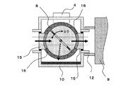
こうした測定精度の低下や破損を防止するため、実施例4では、図13に示すように、測定器(CCDカメラ)9の前面に、固定したプリズムA、Bと回転ステージ8から成る可変光減衰器を納めたハウジング10を設置し、左手から入射する高強度なレーザ光を適切なレベルにまで減衰させたうえで、右手方向へ出射し、測定器9に入射させている。
なお、プリズムBへの透過減衰光を利用する場合、プリズムA側に反射する成分は、ステージ回転角に応じた角度で飛散するため、これを安全に処理する必要がある。
そこでハウジング10の内部に光吸収構造11を設け飛散成分を確実に吸収する構造としている。特に高強度なレーザ光を減衰する場合は、発熱に対処するためハウジングの水冷化やファンを用いた強制空冷方式を採用することが有効である。
なお、プリズムBへの透過減衰光を利用する場合、プリズムA側に反射する成分は、ステージ回転角に応じた角度で飛散するため、これを安全に処理する必要がある。
そこでハウジング10の内部に光吸収構造11を設け飛散成分を確実に吸収する構造としている。特に高強度なレーザ光を減衰する場合は、発熱に対処するためハウジングの水冷化やファンを用いた強制空冷方式を採用することが有効である。
また、ビームプロファイラをはじめとする光測定器は、各工業分野の規格で定められた形状の受光部12を備えており、この形状に合わせることで別の部品を容易に着脱可能な構造をしている。そこで、本実施例に基づく可変光減衰器のハウジングにもこの規格形状を備えることで、市販のビームプロファイラに簡単に取り付け可能としている。これにより、耐久性の高い可変光減衰器で高強度なレーザ光を確実にかつ高精度に減衰させたのち、高感度カメラに入射させることで、ビームプロファイル測定の信頼性を向上させている。
[実施例5]
光減衰器は、理想的には入射光の減衰過程で、光軸やビーム形状、などその他のパラメータに変化を与えないことが求められる。実施例3、4に示すような三角プリズムを用いる場合、プリズムの回転運動に伴ってプリズム表面への光の入射角が変化するため光線が屈折し、減衰器の前後で光軸の微小なずれが生じるおそれがある。
たとえば一辺25mmの直角プリズム2個で減衰器を構築した場合、±5°の角度範囲で±0.7mmの光軸ずれが生じる。後段に置かれる測定器によっては減衰量の調整によって光が測定器受光部の縁に当たり、不用意な迷光が生じて、測定誤差の原因となる。
光減衰器は、理想的には入射光の減衰過程で、光軸やビーム形状、などその他のパラメータに変化を与えないことが求められる。実施例3、4に示すような三角プリズムを用いる場合、プリズムの回転運動に伴ってプリズム表面への光の入射角が変化するため光線が屈折し、減衰器の前後で光軸の微小なずれが生じるおそれがある。
たとえば一辺25mmの直角プリズム2個で減衰器を構築した場合、±5°の角度範囲で±0.7mmの光軸ずれが生じる。後段に置かれる測定器によっては減衰量の調整によって光が測定器受光部の縁に当たり、不用意な迷光が生じて、測定誤差の原因となる。
そこで、図14に示すような多角形プリズムを用いて減衰器を構築することが考えられる。この例では、プリズムA、Bに、正十二角柱を対角線で二分したものを使用している。これにより、プリズム表面の屈折率境界面におけるレーザ光の入射角、出射角は、ステージ回転角度30°毎にリセットされ、0°に戻る。対向面間間隔は、実施例1~実施例3と同様に固定することで、減衰の前後で光軸がずれず、透過率のみが変化する、理想的な可変減衰器を実現している。
[実施例6]
ただし実施例5においては、原理的に、光軸をずらさずに得られる減衰量の値は段階的に変化することになる。これを解消するには、多角形プリズムの角数を無限に増大させることが考えられる。
そこで、実施例6では、図15に示すように、究極の形態として、プリズムA、Bに半円筒プリズムを用い、対向面間隔を実施例1、2と同様に固定することで、円柱状の光減衰器構造としている。これにより、対向面の角度を連続的に変化させても、プリズムA、Bの表面はレーザ光軸に対して常に正対を維持されるため、減衰の前後で光軸ずれが生じない。
ただし実施例5においては、原理的に、光軸をずらさずに得られる減衰量の値は段階的に変化することになる。これを解消するには、多角形プリズムの角数を無限に増大させることが考えられる。
そこで、実施例6では、図15に示すように、究極の形態として、プリズムA、Bに半円筒プリズムを用い、対向面間隔を実施例1、2と同様に固定することで、円柱状の光減衰器構造としている。これにより、対向面の角度を連続的に変化させても、プリズムA、Bの表面はレーザ光軸に対して常に正対を維持されるため、減衰の前後で光軸ずれが生じない。
しかし、実施例6においても、厳密には、平行に進むレーザ光が円柱状の光減衰器に入射する際、円柱の軸を通過しない光線成分は、プリズムAの表面の凸面で屈折し対向面に到達する光線の入射角に分布が生じる。これは、入射角が大きい成分ほど透過率が低下することになり、減衰の前後でビームプロファイルの変化を招く。
そこで、プリズムA表面における屈折を想定し、プリズムA入射前にこの屈折を補正するレンズ構造13を設置することで、プリズムAから対向面に入る各光線成分の入射角を揃えるようにすると好適である。
そこで、プリズムA表面における屈折を想定し、プリズムA入射前にこの屈折を補正するレンズ構造13を設置することで、プリズムAから対向面に入る各光線成分の入射角を揃えるようにすると好適である。
同様に、透過側のプリズムBの表面における屈折についても補正レンズ14を設置することで、減衰の前後で光軸のシフトやビームプロファイルの変化が起こらない、理想的な可変減衰器を実現している。
なお、本実施例では、プリズムA、Bを単一軸対称の円柱状としているが、半球プリズムを用いて球状の減衰器を構築し、球面モータ等を用いてピッチ角、ヨー角、ロール角を独立に制御する形態としてもよい。
なお、本実施例では、プリズムA、Bを単一軸対称の円柱状としているが、半球プリズムを用いて球状の減衰器を構築し、球面モータ等を用いてピッチ角、ヨー角、ロール角を独立に制御する形態としてもよい。
[実施例7]
実施例7では、光軸のずれや透過ビームの歪が生じる原因を根本から排除することで、実施例6の補正レンズを不要としている。
すなわち、図16に示すように、プリズムA、Bから成る円柱状の可変減衰器の前後に、レーザ光軸に対して正対する面を持つ、透明の軸受素子15を配置している。軸受素子は固定されており、この内側で、バッファ層16を介して、円柱状減衰器が回転する構造としている。バッファ層16には、顕微鏡用油浸オイル等の光学油を用いており、軸受素子と減衰器表面との屈折率を整合させ光学的に一体化すると同時に、摺動部の機械的な潤滑の役割を担う。このように、円柱状の減衰器が回転してもレーザ光が入射、出射する軸受素子表面は、常にレーザ光軸に対して正対を維持する構造とすることで、透過前後で光軸ずれやビーム形状の歪がない、理想的な可変光減衰器を実現している。
実施例7では、光軸のずれや透過ビームの歪が生じる原因を根本から排除することで、実施例6の補正レンズを不要としている。
すなわち、図16に示すように、プリズムA、Bから成る円柱状の可変減衰器の前後に、レーザ光軸に対して正対する面を持つ、透明の軸受素子15を配置している。軸受素子は固定されており、この内側で、バッファ層16を介して、円柱状減衰器が回転する構造としている。バッファ層16には、顕微鏡用油浸オイル等の光学油を用いており、軸受素子と減衰器表面との屈折率を整合させ光学的に一体化すると同時に、摺動部の機械的な潤滑の役割を担う。このように、円柱状の減衰器が回転してもレーザ光が入射、出射する軸受素子表面は、常にレーザ光軸に対して正対を維持する構造とすることで、透過前後で光軸ずれやビーム形状の歪がない、理想的な可変光減衰器を実現している。
[実施例8]
実施例8では、高出力レーザ装置における発振出力をフィードバック制御するため、これまでの実施例によって製造された光減衰器をビームサンプリング素子として用いて、出力モニタリングシステムに適用した一例を示すものである。
通常、レーザ発振器の出力モニタでは、ガラス基板や誘電体多層膜基板によるビームサンプラが用いられているが、これらは素子ひとつあたりで得られる減衰量が十分でないため、後段のモニタ用光センサにはレーザ耐久性を重視した熱型センサを用いたり、サンプリング素子を複数用いて多段化・複合化することで減衰量の不足を補うことでモニタリングを行っている。しかし前者はセンサのS/Nや非直線性の点で、また後者は光学系の大型・複雑化による迷光や誤差要因の増大がネックとなり、モニタリングの精度向上が難しい状況であった。
実施例8では、高出力レーザ装置における発振出力をフィードバック制御するため、これまでの実施例によって製造された光減衰器をビームサンプリング素子として用いて、出力モニタリングシステムに適用した一例を示すものである。
通常、レーザ発振器の出力モニタでは、ガラス基板や誘電体多層膜基板によるビームサンプラが用いられているが、これらは素子ひとつあたりで得られる減衰量が十分でないため、後段のモニタ用光センサにはレーザ耐久性を重視した熱型センサを用いたり、サンプリング素子を複数用いて多段化・複合化することで減衰量の不足を補うことでモニタリングを行っている。しかし前者はセンサのS/Nや非直線性の点で、また後者は光学系の大型・複雑化による迷光や誤差要因の増大がネックとなり、モニタリングの精度向上が難しい状況であった。
そこで本実施例では、図17に示すように、制御対象であるレーザ発振器17から出力されるレーザ光の光路中に、実施例1~7の光減衰器を配置することで、プリズムAへの入射光を、プリズムAへの反射成分と、プリズムBへの透過光とに高い分岐比で分岐させ、プリズムBへの透過減衰光を高速かつ高感度に検出可能な光センサ18により計測している。
光センサ18で検出されたモニタ信号は、演算装置2に送られ、目標値との比較演算を行った後、レーザ光の発振制御回路19にフィードバックされ、レーザ出力Poutを目標値に向かって収束させる制御を行う。
光センサ18で検出されたモニタ信号は、演算装置2に送られ、目標値との比較演算を行った後、レーザ光の発振制御回路19にフィードバックされ、レーザ出力Poutを目標値に向かって収束させる制御を行う。
図17の例では、正六角柱を二等分したプリズムA、Bを用いて所定の減衰量が得られるようにした光減衰器を用い、対向面入射角度を最適化しつつ入射・出射界面を光軸に正対させるプリズム形状とすることで、制御対象のレーザ光に対し理想的な減衰特性が得られるビームサンプラを実現している。
本実施例によれば、モニタ用光センサの感度特性に応じて減衰量を最適化できると同時に、その減衰量を高強度なレーザ光に対しても安定に維持可能であり、コンパクトで高性能なレーザ光出力のモニタリングシステムを、低コストに構築可能である。
特に、実施例1、2で示したように、減衰量を高精度に設定しつつ、モニタ用光センサに感度を校正したものを用いることで、レーザ照射量をトレーサブルに制御・管理することができる。これをレーザ加工装置に適用すれば、加工内容に応じてレーザ照射方法を高度に制御したり、加工品質の精密な管理が可能となる。
本実施例によれば、モニタ用光センサの感度特性に応じて減衰量を最適化できると同時に、その減衰量を高強度なレーザ光に対しても安定に維持可能であり、コンパクトで高性能なレーザ光出力のモニタリングシステムを、低コストに構築可能である。
特に、実施例1、2で示したように、減衰量を高精度に設定しつつ、モニタ用光センサに感度を校正したものを用いることで、レーザ照射量をトレーサブルに制御・管理することができる。これをレーザ加工装置に適用すれば、加工内容に応じてレーザ照射方法を高度に制御したり、加工品質の精密な管理が可能となる。
以上説明したように、本発明によれば、プリズムの対向面間の多軸アライメント作業の高精度化と簡略化を両立させると同時に、アライメント中、減衰量をリアルタイムに計測し所望の値に高精度に調整可能とすることで、高出力レーザに対しても高い耐力が得られる光透過方式の近接場光結合型の光減衰器を低コストに実現することが可能となるので、レーザ加工機用の高出力レーザの減衰を含め、広い分野で適用されることが期待できる。
A、B:プリズム
SA、SB:ステージ
Θin:対向面入射角
d:対向面間隔
Pin:入射光出力(減衰量測定用レーザ)
Pt:透過光出力(減衰量測定用レーザ)
θa:対向面入射角度(減衰量測定用レーザ)
θb:対向面入射角度(対向面間隔測定用レーザ)
Ka:光センサ(減衰量測定用)
Kb:光センサ(対向面間隔測定用)
D:スペーサの厚さ
HA、HB:L型保持部
F:締結機構
1:本発明によるレーザ光減衰器
2:演算装置
3:アクチュエータ駆動回路
4:アクチュエータ
5:接着剤
6:スペーサ
7:走査機構
8:回転ステージ
9:光測定器
10:ハウジング
11:光吸収部
12:接続マウント部
13:補正レンズ(入射側)
14:補正レンズ(出射側)
15:軸受素子
16:バッファ層
17:レーザ発振器
18:光センサ
19:発振制御回路
SA、SB:ステージ
Θin:対向面入射角
d:対向面間隔
Pin:入射光出力(減衰量測定用レーザ)
Pt:透過光出力(減衰量測定用レーザ)
θa:対向面入射角度(減衰量測定用レーザ)
θb:対向面入射角度(対向面間隔測定用レーザ)
Ka:光センサ(減衰量測定用)
Kb:光センサ(対向面間隔測定用)
D:スペーサの厚さ
HA、HB:L型保持部
F:締結機構
1:本発明によるレーザ光減衰器
2:演算装置
3:アクチュエータ駆動回路
4:アクチュエータ
5:接着剤
6:スペーサ
7:走査機構
8:回転ステージ
9:光測定器
10:ハウジング
11:光吸収部
12:接続マウント部
13:補正レンズ(入射側)
14:補正レンズ(出射側)
15:軸受素子
16:バッファ層
17:レーザ発振器
18:光センサ
19:発振制御回路
Claims (12)
- 2つのプリズムA、Bの対向面を直接あるいは所定の厚さを有するスペーサを介して互いに押圧させ、対向面間隔を最小化することでアライメントを初期設定する保持装置と、
この初期設定状態を基準として、前記プリズムA、Bの対向面での近接場光の発生と結合によって、前記プリズムAに入射される光出力に対し、前記プリズムA、Bのいずれか一方を出射する光出力の比率を調整する調整機構と、
前記光出力の比率を測定する計測システムと
からなることを特徴とする、レーザ光減衰器を製造するための製造装置。 - 前記保持装置は、前記プリズムA、Bを、双方の対向面を互いに密着するよう押圧してアライメントの初期設定状態を維持したまま、それぞれステージSA、SB上に固定するものであり、
前記調整機構は、前記ステージSA、SBの少なくとも一方を移動させるものであることを特徴とする請求項1に記載された製造装置。 - 前記保持装置は、前記プリズムA、Bの対向面間に配置された所定の厚さDを有するスペーサにより、両者の対向面間隔を確定させた状態を維持したまま初期設定するとともに、前記プリズムA、Bを互いに押圧することで、両者の対向面間隔を前記スペーサの厚さにより確定する調整機構を兼ね備えていることを特徴とする請求項1に記載された製造装置。
- 前記調整機構は、前記スペーサの形状を、前記プリズムA、Bに付加する押圧力の加減によって変形させることで対向面間隔を可変とするものであることを特徴とする請求項3に記載された製造装置。
- 前記調整機構は、前記スペーサの形状を前記プリズムA、Bの対向面両端において異ならせ、前記プリズムA、Bの対向面に沿って、両者の対向面間隔を変化させることを特徴とする請求項4に記載された製造装置。
- 前記調整機構により予め対向面間隔が確定されている前記プリズムA、Bを、レーザ光に対する基準面を有する台座に固定し、前記台座の基準面を回転させることで、レーザ光の入射角を調節する回転調節機構をさらに備えていることを特徴とする請求項2から請求項5のいずれか1項に記載された製造装置。
- 前記調整機構により、前記光出力の比率が調整された状態で、前記プリズムA、Bが固定されている、請求項1から請求項6のいずれか1項に記載された製造装置により製造されたレーザ光減衰器。
- 固定された前記プリズムA、Bがレーザ光に対する基準面を有する台座に固定され、前記台座の基準面を保ちつつ、レーザ光の入射位置を変化させることにより、減衰量を調整可能としたことを特徴とする請求項7に記載されたレーザ光減衰器。
- 固定された前記プリズムA、Bがレーザ光に対する基準面を有する台座に固定され、前記台座の基準面を回転させ、レーザ光の入射角を変化させることにより、減衰量を調整可能としたことを特徴とする請求項7に記載されたレーザ光減衰器。
- 固定された前記プリズムA、Bは、前記調整機構の回転軸に対して軸対称の形状をなすことを特徴とする請求項9に記載されたレーザ光減衰器。
- 固定された前記プリズムA、Bの前後の少なくとも一方に、レンズ状の光学素子を設置することで、固定された前記プリズムA、Bによるレーザ光の屈折を補正することを特徴とする、請求項9または請求項10に記載されたレーザ光減衰器。
- 2つのプリズムA、Bの対向面を直接あるいは所定の厚さを有するスペーサを介して互いに押圧させることで対向面間隔を最小化し、アライメントの初期状態を設定する第1の工程と、
初期設定状態を基準として、前記プリズムA、Bの対向面での近接場光の発生と結合によって、前記プリズムAに入射される光出力に対し、前記プリズムA、Bのいずれか一方を出射する光出力の比率を調整機構を用いて調整する第2の工程と、
前記光出力の比率を、減衰量を計測する計測システムを用いて測定する第3の工程と、
前記計測システムによる測定値に基づいて前記調整機構を作動させ、前記光出力の比率が目標値となった状態で、前記プリズムA、Bを互いに固定する第4の工程と、
からなることを特徴とするレーザ光減衰器の製造方法。
Priority Applications (1)
| Application Number | Priority Date | Filing Date | Title |
|---|---|---|---|
| JP2018564600A JPWO2018139486A1 (ja) | 2017-01-26 | 2018-01-24 | レーザ光減衰器の製造装置、この製造装置により製造されたレーザ光減衰器及びこのレーザ光減衰器の製造方法 |
Applications Claiming Priority (2)
| Application Number | Priority Date | Filing Date | Title |
|---|---|---|---|
| JP2017012500 | 2017-01-26 | ||
| JP2017-012500 | 2017-01-26 |
Publications (1)
| Publication Number | Publication Date |
|---|---|
| WO2018139486A1 true WO2018139486A1 (ja) | 2018-08-02 |
Family
ID=62979460
Family Applications (1)
| Application Number | Title | Priority Date | Filing Date |
|---|---|---|---|
| PCT/JP2018/002122 Ceased WO2018139486A1 (ja) | 2017-01-26 | 2018-01-24 | レーザ光減衰器の製造装置、この製造装置により製造されたレーザ光減衰器及びこのレーザ光減衰器の製造方法 |
Country Status (2)
| Country | Link |
|---|---|
| JP (1) | JPWO2018139486A1 (ja) |
| WO (1) | WO2018139486A1 (ja) |
Cited By (5)
| Publication number | Priority date | Publication date | Assignee | Title |
|---|---|---|---|---|
| JP2020126194A (ja) * | 2019-02-06 | 2020-08-20 | 浜松ホトニクス株式会社 | 光学素子 |
| CN117030205A (zh) * | 2023-08-15 | 2023-11-10 | 中山市光大光学仪器有限公司 | 一种组合棱镜综合透过率的检测方法及检测系统 |
| US20250027810A1 (en) * | 2023-07-19 | 2025-01-23 | Oren Aharon | Sampling High Power Beam Profiling |
| CN119826964A (zh) * | 2024-12-26 | 2025-04-15 | 中红外激光研究院(江苏)有限公司 | 基于python的中红外异型结构光束的光束质量测试装置和方法 |
| JP2025128066A (ja) * | 2020-01-31 | 2025-09-02 | スマート フォトニクス ホールディングス ビー.ブイ. | フォトニック集積回路及び方法 |
Citations (7)
| Publication number | Priority date | Publication date | Assignee | Title |
|---|---|---|---|---|
| JPH04331910A (ja) * | 1991-05-02 | 1992-11-19 | Hamamatsu Photonics Kk | ビ−ムスプリッタ |
| JPH0933339A (ja) * | 1995-07-21 | 1997-02-07 | Nikon Corp | 光監視方法および装置 |
| JPH09101466A (ja) * | 1995-10-06 | 1997-04-15 | Nikon Corp | 光量制御を行なうための光学素子 |
| JP2006074035A (ja) * | 2004-08-24 | 2006-03-16 | Asml Netherlands Bv | リソグラフィ装置用可変減衰器 |
| JP2009192706A (ja) * | 2008-02-13 | 2009-08-27 | Hoya Corp | 非偏光ビームスプリッター及びそれを利用した光学計測機器 |
| JP2012215656A (ja) * | 2011-03-31 | 2012-11-08 | Fujifilm Corp | プリズム装置の製造方法及びプリズム装置並びにプロジェクタ装置 |
| WO2017209277A1 (ja) * | 2016-06-03 | 2017-12-07 | 国立研究開発法人産業技術総合研究所 | 減衰量可変の光減衰器を用いたレーザ出力制御装置 |
-
2018
- 2018-01-24 WO PCT/JP2018/002122 patent/WO2018139486A1/ja not_active Ceased
- 2018-01-24 JP JP2018564600A patent/JPWO2018139486A1/ja active Pending
Patent Citations (7)
| Publication number | Priority date | Publication date | Assignee | Title |
|---|---|---|---|---|
| JPH04331910A (ja) * | 1991-05-02 | 1992-11-19 | Hamamatsu Photonics Kk | ビ−ムスプリッタ |
| JPH0933339A (ja) * | 1995-07-21 | 1997-02-07 | Nikon Corp | 光監視方法および装置 |
| JPH09101466A (ja) * | 1995-10-06 | 1997-04-15 | Nikon Corp | 光量制御を行なうための光学素子 |
| JP2006074035A (ja) * | 2004-08-24 | 2006-03-16 | Asml Netherlands Bv | リソグラフィ装置用可変減衰器 |
| JP2009192706A (ja) * | 2008-02-13 | 2009-08-27 | Hoya Corp | 非偏光ビームスプリッター及びそれを利用した光学計測機器 |
| JP2012215656A (ja) * | 2011-03-31 | 2012-11-08 | Fujifilm Corp | プリズム装置の製造方法及びプリズム装置並びにプロジェクタ装置 |
| WO2017209277A1 (ja) * | 2016-06-03 | 2017-12-07 | 国立研究開発法人産業技術総合研究所 | 減衰量可変の光減衰器を用いたレーザ出力制御装置 |
Cited By (8)
| Publication number | Priority date | Publication date | Assignee | Title |
|---|---|---|---|---|
| JP2020126194A (ja) * | 2019-02-06 | 2020-08-20 | 浜松ホトニクス株式会社 | 光学素子 |
| JP7381205B2 (ja) | 2019-02-06 | 2023-11-15 | 浜松ホトニクス株式会社 | 光学素子 |
| JP2025128066A (ja) * | 2020-01-31 | 2025-09-02 | スマート フォトニクス ホールディングス ビー.ブイ. | フォトニック集積回路及び方法 |
| US20250027810A1 (en) * | 2023-07-19 | 2025-01-23 | Oren Aharon | Sampling High Power Beam Profiling |
| US12247869B2 (en) * | 2023-07-19 | 2025-03-11 | Oren Aharon | Sampling high power beam profiling |
| CN117030205A (zh) * | 2023-08-15 | 2023-11-10 | 中山市光大光学仪器有限公司 | 一种组合棱镜综合透过率的检测方法及检测系统 |
| CN117030205B (zh) * | 2023-08-15 | 2024-02-02 | 中山市光大光学仪器有限公司 | 一种组合棱镜综合透过率的检测方法及检测系统 |
| CN119826964A (zh) * | 2024-12-26 | 2025-04-15 | 中红外激光研究院(江苏)有限公司 | 基于python的中红外异型结构光束的光束质量测试装置和方法 |
Also Published As
| Publication number | Publication date |
|---|---|
| JPWO2018139486A1 (ja) | 2019-11-07 |
Similar Documents
| Publication | Publication Date | Title |
|---|---|---|
| JPWO2018139486A1 (ja) | レーザ光減衰器の製造装置、この製造装置により製造されたレーザ光減衰器及びこのレーザ光減衰器の製造方法 | |
| JP6846752B2 (ja) | 減衰量可変の光減衰器を用いたレーザ出力制御装置 | |
| CN109669226B (zh) | 一种基于超表面透镜组阵列的激光雷达扫描装置及其设计方法 | |
| KR102741489B1 (ko) | 공초점 광학 프로트랙터 | |
| US8810792B2 (en) | Polarization compensated beam splitter and diagnostic system for high power laser systems | |
| CN111864524B (zh) | 一种激光输出稳定性的监测与反馈控制系统 | |
| US11428784B2 (en) | Distance measuring apparatus with high signal dynamics and a reference light path matched thereto | |
| JP2010522998A (ja) | ビーム安定化ファイバレーザ | |
| US20090180105A1 (en) | Swept-Angle SPR Measurement System | |
| US20230073406A1 (en) | Micro-thrust and micro-impulse application device and method based on light pressure principle | |
| JP2018519554A (ja) | 出力スケーリング可能な非線形光波長コンバータ | |
| CN108459367B (zh) | 高对比度啁啾体光栅及其提高啁啾脉冲对比度的控制方法 | |
| KR20130020773A (ko) | 편광 출력 레이저 빔의 고속 강도 변화 달성 방법 | |
| CN108318736B (zh) | 压电陶瓷响应频率的非接触式测量装置及测量方法 | |
| TWI452257B (zh) | State measurement device and state measurement method | |
| JP4732569B2 (ja) | コーティングの光学的な層厚さを連続的に決定するための方法 | |
| US20150160072A1 (en) | Oriented backscattering wide dynamic-range optical radiation sensor | |
| CN107589622B (zh) | 零级衍射可调的激光投影装置 | |
| Kral | Automatic beam alignment system for a pulsed infrared laser | |
| JP2018197678A (ja) | 距離測定装置 | |
| CN103543524B (zh) | 能够保持原偏振态的连续衰减器 | |
| CN103197511B (zh) | 光刻机能量传感器的性能测量装置和测量方法 | |
| US20180087959A1 (en) | Laser power and energy sensor using anisotropic thermoelectric material | |
| TW202240142A (zh) | 用於改進的光散射偏振量測的光源強度控制系統和方法 | |
| JP2009271325A (ja) | レーザ強度分布変換装置 |
Legal Events
| Date | Code | Title | Description |
|---|---|---|---|
| 121 | Ep: the epo has been informed by wipo that ep was designated in this application |
Ref document number: 18744551 Country of ref document: EP Kind code of ref document: A1 |
|
| ENP | Entry into the national phase |
Ref document number: 2018564600 Country of ref document: JP Kind code of ref document: A |
|
| NENP | Non-entry into the national phase |
Ref country code: DE |
|
| 122 | Ep: pct application non-entry in european phase |
Ref document number: 18744551 Country of ref document: EP Kind code of ref document: A1 |