WO2018139155A1 - チェーン及びチェーンコンベヤ - Google Patents
チェーン及びチェーンコンベヤ Download PDFInfo
- Publication number
- WO2018139155A1 WO2018139155A1 PCT/JP2017/046798 JP2017046798W WO2018139155A1 WO 2018139155 A1 WO2018139155 A1 WO 2018139155A1 JP 2017046798 W JP2017046798 W JP 2017046798W WO 2018139155 A1 WO2018139155 A1 WO 2018139155A1
- Authority
- WO
- WIPO (PCT)
- Prior art keywords
- pair
- chain
- roller
- path
- link plates
- Prior art date
- Legal status (The legal status is an assumption and is not a legal conclusion. Google has not performed a legal analysis and makes no representation as to the accuracy of the status listed.)
- Ceased
Links
Images



Classifications
-
- B—PERFORMING OPERATIONS; TRANSPORTING
- B65—CONVEYING; PACKING; STORING; HANDLING THIN OR FILAMENTARY MATERIAL
- B65G—TRANSPORT OR STORAGE DEVICES, e.g. CONVEYORS FOR LOADING OR TIPPING, SHOP CONVEYOR SYSTEMS OR PNEUMATIC TUBE CONVEYORS
- B65G17/00—Conveyors having an endless traction element, e.g. a chain, transmitting movement to a continuous or substantially-continuous load-carrying surface or to a series of individual load-carriers; Endless-chain conveyors in which the chains form the load-carrying surface
- B65G17/06—Conveyors having an endless traction element, e.g. a chain, transmitting movement to a continuous or substantially-continuous load-carrying surface or to a series of individual load-carriers; Endless-chain conveyors in which the chains form the load-carrying surface having a load-carrying surface formed by a series of interconnected, e.g. longitudinal, links, plates, or platforms
-
- F—MECHANICAL ENGINEERING; LIGHTING; HEATING; WEAPONS; BLASTING
- F16—ENGINEERING ELEMENTS AND UNITS; GENERAL MEASURES FOR PRODUCING AND MAINTAINING EFFECTIVE FUNCTIONING OF MACHINES OR INSTALLATIONS; THERMAL INSULATION IN GENERAL
- F16G—BELTS, CABLES, OR ROPES, PREDOMINANTLY USED FOR DRIVING PURPOSES; CHAINS; FITTINGS PREDOMINANTLY USED THEREFOR
- F16G13/00—Chains
- F16G13/02—Driving-chains
- F16G13/06—Driving-chains with links connected by parallel driving-pins with or without rollers so-called open links
Definitions
- the present invention relates to a chain and a chain conveyor.
- a chain shown in Patent Document 1 is known as a chain used in a chain conveyor for transporting an object to be transported.
- Such a chain is formed in an endless shape, and has two rows of link plate rows including an inner link plate and an outer link plate.
- Each of these two link plate rows has a bendable structure in which inner link plates and outer link plates are alternately connected by pins.
- a roller is rotatably provided inside the two link plate rows.
- the roller is configured to mesh with the teeth of the drive sprocket and the driven sprocket.
- Guide rollers are rotatably supported by pins on both outer sides of the two rows of link plate rows.
- endless guide rails are provided so as to extend along the chain movement path. The guide roller is configured to roll on the guide rail.
- the chain as described above receives the load with a guide roller. For this reason, it is necessary to increase the outer diameter of the guide roller so that the chain can withstand a greater load. However, if the outer diameter of the guide roller is made too large, there is a problem that it becomes difficult to manufacture the chain because the interval between the adjacent guide rollers becomes narrow.
- An object of the present invention is to provide a chain and a chain conveyor that can be easily manufactured while ensuring load resistance.
- the chain includes a pair of inner link plates disposed opposite to each other, a cylindrical bush having both ends joined to the pair of inner link plates, and the bush.
- a pin that is rotatably inserted into the bush, a cylindrical first roller that is rotatable around the bush and engageable with the sprocket, and a pair of inner link plates that are sandwiched from the outside.
- the outer diameter of the second roller is set to be 70% or more and 90% or less of the chain pitch.
- the outer diameter of the second roller is set to be 70% or more and 90% or less of the chain pitch, while ensuring the interval between the second rollers adjacent in the longitudinal direction of the chain,
- the outer diameter of the second roller can be made larger. Therefore, the chain can be easily manufactured while ensuring the load resistance of the chain.
- the chain conveyor includes a linear first path portion, a linear second path portion disposed below the first path portion, the first path portion, An endless path having a curved third path section that connects the ends of the second path section, and a pair of endless chains configured to circulate along the endless path; A pair of guide rails that support the second roller of the pair of chains and guide the pair of chains along the endless path; and a mounting surface on which an object to be conveyed is mounted; A plurality of planar members that are coupled to the chain and circulate along the endless path together with the chain, two pairs of sprockets around which the pair of chains are wound in the third path portion, and two pairs of the above Sprocket And a driving unit for rotationally driving one of the.
- a chain having excellent load resistance can be easily manufactured.
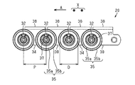
- FIG. 4 is a side view of FIG. 3.
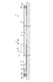
- the side surface schematic diagram which shows the guide rail and its periphery in a chain conveyor.
- the chain conveyor 11 is installed on the floor surface F, and is extended in parallel with the conveyance direction A (left direction in FIG. 1) of the to-be-conveyed object H.
- the chain conveyor 11 includes a linear first path portion 12, a linear second path portion 13 disposed below the first path portion 12, and ends of the first path portion 12 and the second path portion 13.
- An endless path 15 having two curved third path portions 14 a and 14 b that connect the sections to each other, and an endless transport unit 16 that circulates along the endless path 15 are provided.
- the transport unit 16 includes a pair of endless chains 20 and a plurality of planar members 22 each connecting the pair of chains 20 to each other.
- the planar member 22 has a rectangular plate shape and forms a placement surface 21 on which the transported object H is placed.
- one third path portion 14 a is located at the front end of the chain conveyor 11 in the transport direction A
- the other third path portion 14 b is the transport direction in the chain conveyor 11. It is located at the rear end of A.
- the chain conveyor 11 includes a pair of sprockets 23a around which the pair of chains 20 are wound in the third path portion 14a, a pair of sprockets 23b around which the pair of chains 20 are wound in the third path portion 14b, and two pairs of sprockets 23a. , 23b, and a drive unit 24 that rotationally drives a pair of sprockets 23a.
- the drive unit 24 is configured by, for example, a motor and a speed reducer.
- the sprockets 23a and 23b are constituted by involute sprockets, for example.
- each chain 20 includes a pair of inner link plates 30 and a pair of outer link plates 34 that are alternately connected by pins 32.
- the pair of outer link plates 34 are disposed so as to sandwich the pair of inner link plates 30 from the outside, and both end portions of the pins 32 are joined to the outer link plate so as not to rotate.
- the pair of inner link plates 30 are disposed opposite to each other in the width direction X orthogonal to the transport direction A.
- Two cylindrical bushes 31 are provided between the pair of inner link plates 30, and both ends of each bush 31 are joined to the inner link plate 30 so as not to rotate.
- the pin 32 is rotatably inserted into the bush 31.
- Each chain 20 further includes a cylindrical first roller 33 that is rotatably disposed around the bush 31. The first roller 33 can be engaged (engaged) with the sprockets 23a and 23b.
- a pin 32 protrudes outward in the width direction X from one of the pair of outer link plates 34.
- a cylindrical second roller 35 is provided at the protruding portion of the pin 32 so as to be rotatable about the axis of the pin 32. Specifically, the second roller 35 is rotatably supported on the pin 32 via a bearing 36.
- a nut 37 is screwed into a screw portion (not shown) formed at the tip of the pin 32 so that the second roller 35 does not fall out of the pin 32.
- the pair of outer link plates 34 and the pair of inner link plates 30 on the outer link plate 34 and the inner link plate 30 located on the outer side in the width direction X have rectangular plate-shaped attachment portions 38 on the inner side in the width direction X. It is integrally formed so as to protrude.
- a pair of inner link plates 30 and a pair of outer link plates 34 are alternately connected in series and endlessly via a bush 31 and pins 32 to form a chain 20.
- Each second roller 35 is located at both ends in the width direction X of the transport unit 16.
- Each of the second rollers 35 includes a roller main body portion 35a, and an annular flange portion 35b formed so as to protrude radially outward from the base end portion (end portion on the outer link plate 34 side) of the roller main body portion 35a. have. Therefore, the outer diameter of the flange portion 35b is slightly larger than the outer diameter of the roller main body portion 35a.
- the outer diameter D of the roller body 35a of the second roller 35 is set to be 70% or more and 90% or less of the chain pitch P (the distance between the centers of two pins 32 adjacent in the longitudinal direction of the chain 20). It is preferable to set the chain pitch P to be 75% or more and 85% or less. In the present embodiment, the outer diameter D of the roller body 35a of the second roller 35 is set to be about 80% of the chain pitch P.
- the outer diameter D of the roller body 35a of the second roller 35 is less than 70% of the chain pitch P, the load resistance of the second roller 35 may be insufficient.
- the outer diameter D of the roller main body portion 35a of the second roller 35 exceeds 90% of the chain pitch P, the interval between the flange portions 35b of the second rollers 35 adjacent in the transport direction A is too small. For this reason, the second roller 35 must be manufactured with high dimensional accuracy, making it difficult to manufacture the chain 20.
- the outer diameter of the first roller 33 is preferably set to be 50% or less of the outer diameter D of the roller main body portion 35a of the second roller 35.
- each planar member 22 connects a pair of chains 20 in a state of being arranged at equal intervals in the transport direction A, and circulates and moves along the endless path 15 (see FIG. 1) together with the pair of chains 20.
- the chain conveyor 11 includes a pair of guide rails 39.
- the pair of guide rails 39 guides the plurality of second rollers 35 of the pair of chains 20 of the transport unit 16 along the endless path 15. That is, the pair of guide rails 39 supports the second roller 35 of the pair of chains 20 and guides the pair of chains 20 along the endless path 15.
- Each guide rail 39 includes an upper section 39a that guides while supporting each second roller 35 in the first path portion 12, and a lower section 39b that guides while supporting each second roller 35 in the second path portion 13. It has.
- Both end portions of the upper section 39a are located immediately above the central portions of the sprockets 23a and 23b, respectively, when viewed from the width direction X.
- the pitch circle of the sprocket 23a is PCA
- the pitch circle of the sprocket 23b is PCB.
- Each of the third path portions 14a and 14b is provided with a guide rail non-arrangement region NP in which the guide rail 39 is not arranged. Accordingly, the second rollers 35 are not guided by the guide rails 39 in the third path portions 14a and 14b.
- Each guide rail 39 is comprised, for example with a strip
- the transported object H is transported in the transport direction A as follows.
- the transported object H is placed on the placement surface 21 of the transport unit 16 in the first path portion 12 and the sprocket 23a is driven to rotate counterclockwise in FIG. 1, each tooth of the sprocket 23a is chained. It rotates while meshing with 20 first rollers 33 sequentially.
- the outer diameter D of the roller body 35a of the second roller 35 is set to be about 80% of the chain pitch P. For this reason, the load resistance of the roller main body portion 35a of the second roller 35 can be sufficiently ensured. In addition, since the interval between the flange portions 35b of the second rollers 35 adjacent to each other in the transport direction A in the chain 20 can be sufficiently secured, the dimensional accuracy of the second roller 35 can be reduced. Therefore, the chain 20 can be easily manufactured while ensuring the load resistance of the chain 20.
- the guide rails 39 for guiding the second rollers 35 of the chain 20 do not exist in the curved third path portions 14a and 14b, the movement of the chain 20 in the third path portions 14a and 14b is caused by the guide rail 39. Not disturbed by. Accordingly, the chain 20 smoothly circulates and moves along the endless path 15, so that the object to be transported H on the placement surface 21 of the transport unit 16 is stably transported in the transport direction A.
- each of the first rollers 33 of the chain 20 has its center when it is on the pitch circle PCA. It meshes with the sprocket 23a. For this reason, since the vertical movement of the chain 20 is suppressed, the speed fluctuation
- the outer diameter D of the roller body 35a of the second roller 35 is set to be 70% or more and 90% or less of the chain pitch P. For this reason, it is possible to increase the outer diameter D of the roller main body portion 35a of the second roller 35 while securing the interval between the flange portions 35b of the second rollers 35 adjacent in the transport direction A (longitudinal direction of the chain 20). it can. Therefore, the chain 20 can be easily manufactured while ensuring the load resistance of the chain 20.
- a guide rail non-arrangement region NP is provided in each of the third path portions 14a and 14b. For this reason, since the movement of the chain 20 in the third path portions 14 a and 14 b is not hindered by the guide rail 39, the chain 20 can be smoothly circulated along the endless path 15.
- the guide rail 39 is disposed in each of the curved third path portions 14a and 14b, the guide rail 39 is raised in the moving path of the second roller 35 when the chain 20 is guided by the sprockets 23a and 23b. It is necessary to match with dimensional accuracy.
- the second roller 35 does not roll smoothly along the guide rail 39, and the third path portions 14a, 14b of the chain 20 There is a risk that the guide rail 39 hinders the movement at this point.
- the chain conveyor 11 receives the load of the transported object H on the upper section 39a of the guide rail 39 by the roller body 35a of each second roller 35 without receiving the load on each first roller 33. For this reason, even if the outer diameter D of the roller body 35a of each second roller 35 is increased in order to increase the load resistance of the chain conveyor 11, the distance between the adjacent first rollers 33 and the chain pitch P do not change. It is not necessary to change the outer diameter and the number of teeth of the sprockets 23a and 23b. Therefore, the chain conveyor 11 can keep the outer diameters of the sprockets 23a and 23b small even when the load resistance is increased. It can be suitably used as a chain conveyor.
- each first roller 33 and the chain pitch P are increased and the outer diameters of the sprockets 23a and 23b are not changed, it is necessary to reduce the number of teeth of the sprockets 23a and 23b.
- a polygonal movement called a chordal action is more likely to occur when the chain 20 meshes with the sprockets 23a and 23b.
- the chain conveyor 11 can be used as a low-floor type chain conveyor, the speed fluctuation of the chain 20 becomes large, and thus there is a problem that the transported object H cannot be stably transported. .
Landscapes
- Engineering & Computer Science (AREA)
- Mechanical Engineering (AREA)
- General Engineering & Computer Science (AREA)
- Chain Conveyers (AREA)
Abstract
チェーン(20)は、互いに対向して離れて配置される一対の内リンクプレート(30)と、一対の内リンクプレート(30)に両端部がそれぞれ接合される筒状のブシュ(31)と、ブシュ(31)に回転可能に挿入されるピン(32)と、ブシュ(31)の周りに回転可能に配置され、且つスプロケットと係合可能な第1ローラ(33)と、一対の内リンクプレート(30)を外側から挟むように配置されるとともに、ピン(32)の両端部がそれぞれ接合される一対の外リンクプレート(34)と、一対の外リンクプレート(34)の外側にピン(32)の軸線を中心に回転可能に設けられた筒状の第2ローラ(35)とを備える。第2ローラ(35)の外径は、チェーンピッチの70%以上90%以下となるように設定されている。
Description
本発明は、チェーン及びチェーンコンベヤに関する。
従来、被搬送物を搬送するチェーンコンベヤに用いられるチェーンとして、例えば特許文献1に示すチェーンが知られている。こうしたチェーンは、無端状に形成され、内リンクプレート及び外リンクプレートからなるリンクプレート列を2列有している。これら2列のリンクプレート列は、それぞれピンによって内リンクプレート及び外リンクプレートが交互に連結された屈曲可能な構成になっている。
2列のリンクプレート列の内側には、ローラが回転可能に設けられている。ローラは、駆動スプロケット及び従動スプロケットの歯と噛み合うように構成されている。2列のリンクプレート列の両外側には、ガイドローラがピンに回転可能に支持されている。チェーンの移動経路の両側方には、無端状のガイドレールがチェーンの移動経路に沿って延びるように設けられている。ガイドローラは、ガイドレール上を転動するように構成されている。
上述のようなチェーンは、例えば被搬送物の荷重がかかった場合、その荷重をガイドローラで受けるようになっている。このため、チェーンをより大きい荷重に耐え得るようにするためには、ガイドローラの外径をより大きくする必要がある。しかし、ガイドローラの外径を大きくしすぎると、隣り合うガイドローラ同士の間隔が狭くなってチェーンの製造が困難になるという問題がある。
本発明の目的は、耐荷重性を確保しつつ、容易に製造することができるチェーン及びチェーンコンベヤを提供することにある。
本発明の一態様によれば、チェーンは、互いに対向して離れて配置される一対の内リンクプレートと、前記一対の内リンクプレートに両端部がそれぞれ接合される筒状のブシュと、前記ブシュに回転可能に挿入されるピンと、前記ブシュの周りに回転可能に配置され、且つスプロケットと係合可能な筒状の第1ローラと、前記一対の内リンクプレートを外側から挟むように配置されるとともに、前記ピンの両端部がそれぞれ接合される一対の外リンクプレートと、前記一対の外リンクプレートの外側に前記ピンの軸線を中心に回転可能に設けられた筒状の第2ローラとを備える。前記第2ローラの外径は、チェーンピッチの70%以上90%以下となるように設定されている。
この構成によれば、第2ローラの外径がチェーンピッチの70%以上90%以下となるように設定されているため、チェーンの長手方向で隣り合う第2ローラ同士の間隔を確保しつつ、第2ローラの外径をより大きくすることができる。したがって、チェーンの耐荷重性を確保しつつ、チェーンを容易に製造することができる。
本発明の別の態様によれば、チェーンコンベヤは、直線状の第1経路部と、前記第1経路部の下側に配置された直線状の第2経路部と、前記第1経路部及び前記第2経路部の端部同士をそれぞれ接続する湾曲状の第3経路部とを有した無端状経路と、前記無端状経路に沿って循環移動する無端状の一対の上記構成のチェーンと、一対の前記チェーンの前記第2ローラを支持するとともに一対の前記チェーンを前記無端状経路に沿ってガイドする一対のガイドレールと、被搬送物が載置される載置面を形成し、且つ一対の前記チェーンに連結されて当該チェーンと共に前記無端状経路に沿って循環移動する複数の平面部材と、前記第3経路部において一対の前記チェーンが巻き掛けられる二対のスプロケットと、二対の前記スプロケットのうちの一方を回転駆動する駆動部とを備える。
この構成によれば、上記チェーンと同様の作用効果を得ることができる。
本発明によれば、耐荷重性に優れるチェーンを容易に製造することができる。
以下、チェーンコンベヤの一実施形態を図面に従って説明する。
図1及び図2に示すように、チェーンコンベヤ11は、床面F上に設置され、被搬送物Hの搬送方向A(図1では左方向)と平行に延びている。チェーンコンベヤ11は、直線状の第1経路部12と、第1経路部12の下側に配置された直線状の第2経路部13と、第1経路部12及び第2経路部13の端部同士をそれぞれ接続する湾曲状の2つの第3経路部14a,14bとを有した無端状経路15と、無端状経路15に沿って循環移動する無端状の搬送ユニット16とを備えている。
図1及び図2に示すように、チェーンコンベヤ11は、床面F上に設置され、被搬送物Hの搬送方向A(図1では左方向)と平行に延びている。チェーンコンベヤ11は、直線状の第1経路部12と、第1経路部12の下側に配置された直線状の第2経路部13と、第1経路部12及び第2経路部13の端部同士をそれぞれ接続する湾曲状の2つの第3経路部14a,14bとを有した無端状経路15と、無端状経路15に沿って循環移動する無端状の搬送ユニット16とを備えている。
搬送ユニット16は、無端状の一対のチェーン20と、各々が一対のチェーン20同士を連結する複数の平面部材22とを備えている。平面部材22は矩形板状であり、被搬送物Hが載置される載置面21を形成する。2つの第3経路部14a,14bのうち、一方の第3経路部14aはチェーンコンベヤ11における搬送方向Aの前方の端部に位置し、他方の第3経路部14bはチェーンコンベヤ11における搬送方向Aの後方の端部に位置している。
チェーンコンベヤ11は、第3経路部14aにおいて一対のチェーン20が巻き掛けられる一対のスプロケット23aと、第3経路部14bにおいて一対のチェーン20が巻き掛けられる一対のスプロケット23bと、二対のスプロケット23a,23bのうちの一方である一対のスプロケット23aを回転駆動する駆動部24とを備えている。駆動部24は、例えばモーター及び減速機などによって構成される。スプロケット23a,23bは、例えばインボリュートスプロケットによって構成される。
図3及び図4に示すように、各チェーン20は、ピン32によって交互に連結される一対の内リンクプレート30及び一対の外リンクプレート34を備えている。一対の外リンクプレート34は一対の内リンクプレート30を外側から挟むように配置され、ピン32の両端部が外リンクプレートに回転不能に接合されている。一対の内リンクプレート30は、搬送方向Aと直交する幅方向Xにおいて互いに対向して離れて配置される。一対の内リンクプレート30の間には2つの筒状のブシュ31が設けられており、各ブシュ31の両端部が内リンクプレート30に回転不能に接合されている。ピン32は、ブシュ31に回転可能に挿入されている。各チェーン20はさらに、ブシュ31の周りに回転可能に配置された筒状の第1ローラ33を備えている。第1ローラ33はスプロケット23a,23bと係合(噛合)可能である。
一対の外リンクプレート34のうちの片方からはピン32が幅方向Xの外側に突出している。当該ピン32の突出部分には筒状の第2ローラ35がピン32の軸線を中心に回転可能に設けられている。具体的には、ピン32には、第2ローラ35がベアリング36を介して回転可能に支持されている。ピン32の先端部に形成された図示しないねじ部には、ピン32から第2ローラ35が抜け落ちないように、ナット37が螺合されている。
一対の外リンクプレート34及び一対の内リンクプレート30における幅方向Xの外側に位置する方の外リンクプレート34及び内リンクプレート30には、矩形板状の取付部38が幅方向Xの内側に突出するように一体形成されている。そして、一対の内リンクプレート30と一対の外リンクプレート34とが、ブシュ31及びピン32を介して回転可能に交互に直列且つ無端状に連結されてチェーン20を形成している。各第2ローラ35は、搬送ユニット16における幅方向Xの両端部に位置している。
各第2ローラ35は、ローラ本体部35aと、ローラ本体部35aの基端部(外リンクプレート34側の端部)から径方向外側に突出するように形成された円環状のフランジ部35bとを有している。したがって、フランジ部35bの外径は、ローラ本体部35aの外径よりも若干大きくなっている。
第2ローラ35のローラ本体部35aの外径Dは、チェーンピッチP(チェーン20における長手方向で隣り合う2つのピン32の中心同士の距離)の70%以上90%以下となるように設定することが好ましく、チェーンピッチPの75%以上85%以下となるように設定することがより好ましい。本実施形態では、第2ローラ35のローラ本体部35aの外径DがチェーンピッチPの約80%となるように設定されている。
第2ローラ35のローラ本体部35aの外径DがチェーンピッチPの70%未満である場合には、第2ローラ35の耐荷重性が不足するおそれがある。一方、第2ローラ35のローラ本体部35aの外径DがチェーンピッチPの90%を超える場合には、搬送方向Aで隣り合う第2ローラ35のフランジ部35b同士の間隔が狭くなりすぎる。このため、第2ローラ35を高い寸法精度で製造しなければならなくなるので、チェーン20の製造が困難になる。一方、第1ローラ33の外径は、第2ローラ35のローラ本体部35aの外径Dの50%以下となるように設定することが好ましい。
図2に示すように、一対のチェーン20において幅方向Xで対向する全ての取付部38同士には、平面部材22が掛け渡された状態でそれぞれ図示しないボルトとナットとによって取り付けられている。各平面部材22は、搬送方向Aに等間隔で並んだ状態で一対のチェーン20を連結し、一対のチェーン20と共に無端状経路15(図1参照)に沿って循環移動する。
図2及び図5に示すように、チェーンコンベヤ11は一対のガイドレール39を備えている。一対のガイドレール39は、搬送ユニット16の一対のチェーン20の複数の第2ローラ35を無端状経路15に沿って案内する。すなわち、一対のガイドレール39は、一対のチェーン20の第2ローラ35を支持するとともに一対のチェーン20を無端状経路15に沿ってガイドする。各ガイドレール39は、第1経路部12において各第2ローラ35を支持しながら案内する上側セクション39aと、第2経路部13において各第2ローラ35を支持しながら案内する下側セクション39bとを備えている。
上側セクション39aの両端部は、幅方向Xから見て、それぞれスプロケット23a,23bの中心部の真上に位置している。図5において、スプロケット23aのピッチ円はPCAとされ、スプロケット23bのピッチ円はPCBとされている。第3経路部14a,14bの各々には、ガイドレール39が配置されないガイドレール非配置領域NPが設けられている。したがって、第3経路部14a,14bでは、各第2ローラ35がガイドレール39によってガイドされない。
搬送ユニット16は、駆動部24の駆動力がスプロケット23aを介して一対のチェーン20に伝達される際に、一対のチェーン20の各第2ローラ35が一対のガイドレール39に案内されることで、無端状経路15に沿って循環移動する。各ガイドレール39は、例えば帯状の板材によって構成される。
次に、チェーンコンベヤ11の作用について説明する。
被搬送物Hは次のようにして搬送方向Aへ搬送される。被搬送物Hが第1経路部12における搬送ユニット16の載置面21上に載置された状態で、スプロケット23aを図1における反時計方向に回転駆動させると、スプロケット23aの各歯がチェーン20の複数の第1ローラ33に順次に噛合しながら回転する。
被搬送物Hは次のようにして搬送方向Aへ搬送される。被搬送物Hが第1経路部12における搬送ユニット16の載置面21上に載置された状態で、スプロケット23aを図1における反時計方向に回転駆動させると、スプロケット23aの各歯がチェーン20の複数の第1ローラ33に順次に噛合しながら回転する。
すると、スプロケット23aから搬送ユニット16に駆動力が伝達され、搬送ユニット16が無端状経路15に沿って図1における反時計方向に周回するように循環移動する。これにより、載置面21上の被搬送物Hが搬送方向Aに搬送される。このとき、搬送ユニット16のチェーン20は、被搬送物Hの荷重を、ガイドレール39の上側セクション39a上において各第2ローラ35のローラ本体部35aで受ける。
本実施形態のチェーン20では、第2ローラ35のローラ本体部35aの外径DがチェーンピッチPの約80%となるように設定されている。このため、第2ローラ35のローラ本体部35aの耐荷重性を十分に確保することができる。加えて、チェーン20における搬送方向Aで隣り合う第2ローラ35のフランジ部35b同士の間隔を十分に確保することができるので、第2ローラ35の寸法精度を低減できる。したがって、チェーン20の耐荷重性を確保しつつ、チェーン20を容易に製造することができる。
また、湾曲状の第3経路部14a,14bにはチェーン20の各第2ローラ35をガイドするガイドレール39が存在しないため、第3経路部14a,14bでのチェーン20の移動がガイドレール39によって妨げられない。したがって、チェーン20が無端状経路15に沿って円滑に循環移動するので、搬送ユニット16の載置面21上の被搬送物Hが搬送方向Aに安定して搬送される。
上側セクション39aは、幅方向Xから見て、スプロケット23aの中心部の真上の位置まで延びているため、チェーン20の各第1ローラ33は、その中心がピッチ円PCA上に来たときにスプロケット23aと噛合する。このため、チェーン20の上下動が抑制されるので、チェーン20が移動する際の速度変動が抑制される。この結果、被搬送物Hが搬送方向Aに向かってより安定して搬送される。
以上詳述した実施形態によれば、次のような効果が発揮される。
(1)チェーン20において、第2ローラ35のローラ本体部35aの外径Dは、チェーンピッチPの70%以上90%以下となるように設定されている。このため、搬送方向A(チェーン20の長手方向)で隣り合う第2ローラ35のフランジ部35b同士の間隔を確保しつつ、第2ローラ35のローラ本体部35aの外径Dを大きくすることができる。したがって、チェーン20の耐荷重性を確保しつつ、チェーン20を容易に製造することができる。
(1)チェーン20において、第2ローラ35のローラ本体部35aの外径Dは、チェーンピッチPの70%以上90%以下となるように設定されている。このため、搬送方向A(チェーン20の長手方向)で隣り合う第2ローラ35のフランジ部35b同士の間隔を確保しつつ、第2ローラ35のローラ本体部35aの外径Dを大きくすることができる。したがって、チェーン20の耐荷重性を確保しつつ、チェーン20を容易に製造することができる。
(2)チェーンコンベヤ11において、第3経路部14a,14bの各々にはガイドレール非配置領域NPが設けられている。このため、チェーン20の第3経路部14a,14bでの移動がガイドレール39によって妨げられないので、無端状経路15に沿ってチェーン20を円滑に循環移動させることができる。一方、湾曲状の第3経路部14a,14bの各々にガイドレール39を配置した場合には、スプロケット23a,23bによってチェーン20が導かれる際の第2ローラ35の移動経路にガイドレール39を高い寸法精度で合わせる必要がある。このため、ガイドレール39やスプロケット23a,23bなどの組み付け精度や寸法精度によっては、ガイドレール39に沿って第2ローラ35が円滑に転動しなくなって、チェーン20の第3経路部14a,14bでの移動がガイドレール39によって妨げられるおそれがある。
(3)チェーンコンベヤ11は、被搬送物Hの荷重を、各第1ローラ33で受けずに、ガイドレール39の上側セクション39a上において各第2ローラ35のローラ本体部35aで受けている。このため、チェーンコンベヤ11の耐荷重性を上げるべく各第2ローラ35のローラ本体部35aの外径Dを大きくしても、隣り合う第1ローラ33同士の間隔及びチェーンピッチPは変わらないので、スプロケット23a,23bの外径も歯数も変える必要がない。したがって、チェーンコンベヤ11は、耐荷重性を上げてもスプロケット23a,23bの外径を小さいまま抑えることができるので、低床タイプ(例えばユーザーがワンステップで乗り降りできる高さ(約300mm)以下)のチェーンコンベヤとして好適に用いることができる。
仮に、チェーンコンベヤ11において、第2ローラ35を省略するとともに各第1ローラ33をガイドレールで支持し、被搬送物Hの荷重を当該ガイドレール上において各第1ローラ33で受けようとすると、チェーンコンベヤ11の耐荷重性を上げるには各第1ローラ33の外径を大きくする必要がある。そして、各第1ローラ33の外径を大きくすると、チェーンピッチPを大きくする必要があるため、スプロケット23a,23bの歯数を変更しないのであれば、スプロケット23a,23bの外径を大きくする必要がある。しかし、スプロケット23a,23bの外径を大きくすると、チェーンコンベヤ11の高さが高くなるので、チェーンコンベヤ11を低床タイプのチェーンコンベヤとして用いることができなくなるという問題がある。
また仮に、各第1ローラ33の外径及びチェーンピッチPを大きくし、且つスプロケット23a,23bの外径を変更しないのであれば、スプロケット23a,23bの歯数を減らす必要がある。しかし、スプロケット23a,23bの歯数を減らすと、チェーン20がスプロケット23a,23bに噛合した際にコーダルアクションと呼ばれる多角形運動がより起こりやすくなる。このため、チェーンコンベヤ11を低床タイプのチェーンコンベヤとして用いることができたとしても、チェーン20の速度変動が大きくなるので、被搬送物Hを安定して搬送することができなくなるという問題がある。
11…チェーンコンベヤ、12…第1経路部、13…第2経路部、14a,14b…第3経路部、15…無端状経路、20…チェーン、21…載置面、22…平面部材、23a,23b…スプロケット、24…駆動部、30…内リンクプレート、31…ブシュ、32…ピン、33…第1ローラ、34…外リンクプレート、35…第2ローラ、39…ガイドレール、D…外径、H…被搬送物、NP…ガイドレール非配置領域、P…チェーンピッチ。
Claims (3)
- チェーンであって、
互いに対向して離れて配置される一対の内リンクプレートと、
前記一対の内リンクプレートに両端部がそれぞれ接合される筒状のブシュと、
前記ブシュに回転可能に挿入されるピンと、
前記ブシュの周りに回転可能に配置され、且つスプロケットと係合可能な筒状の第1ローラと、
前記一対の内リンクプレートを外側から挟むように配置されるとともに、前記ピンの両端部がそれぞれ接合される一対の外リンクプレートと、
前記一対の外リンクプレートの外側に前記ピンの軸線を中心に回転可能に設けられた筒状の第2ローラと、
を備え、
前記第2ローラの外径は、チェーンピッチの70%以上90%以下となるように設定されていることを特徴とするチェーン。 - 直線状の第1経路部と、前記第1経路部の下側に配置された直線状の第2経路部と、前記第1経路部及び前記第2経路部の端部同士をそれぞれ接続する湾曲状の第3経路部とを有した無端状経路と、
前記無端状経路に沿って循環移動する無端状の一対の請求項1に記載のチェーンと、
一対の前記チェーンの前記第2ローラを支持するとともに一対の前記チェーンを前記無端状経路に沿ってガイドする一対のガイドレールと、
被搬送物が載置される載置面を形成し、且つ一対の前記チェーンに連結されて当該チェーンと共に前記無端状経路に沿って循環移動する複数の平面部材と、
前記第3経路部において一対の前記チェーンが巻き掛けられる二対のスプロケットと、
二対の前記スプロケットのうちの一方を回転駆動する駆動部と、
を備えたことを特徴とするチェーンコンベヤ。 - 前記第3経路部の各々には、前記ガイドレールが配置されない領域が設けられていることを特徴とする請求項2に記載のチェーンコンベヤ。
Priority Applications (1)
| Application Number | Priority Date | Filing Date | Title |
|---|---|---|---|
| CN201780073992.2A CN110023210B (zh) | 2017-01-25 | 2017-12-26 | 链式输送机用的链条及链式输送机 |
Applications Claiming Priority (2)
| Application Number | Priority Date | Filing Date | Title |
|---|---|---|---|
| JP2017-011290 | 2017-01-25 | ||
| JP2017011290A JP6573921B2 (ja) | 2017-01-25 | 2017-01-25 | チェーン及びチェーンコンベヤ |
Publications (1)
| Publication Number | Publication Date |
|---|---|
| WO2018139155A1 true WO2018139155A1 (ja) | 2018-08-02 |
Family
ID=62978232
Family Applications (1)
| Application Number | Title | Priority Date | Filing Date |
|---|---|---|---|
| PCT/JP2017/046798 Ceased WO2018139155A1 (ja) | 2017-01-25 | 2017-12-26 | チェーン及びチェーンコンベヤ |
Country Status (3)
| Country | Link |
|---|---|
| JP (1) | JP6573921B2 (ja) |
| CN (1) | CN110023210B (ja) |
| WO (1) | WO2018139155A1 (ja) |
Families Citing this family (1)
| Publication number | Priority date | Publication date | Assignee | Title |
|---|---|---|---|---|
| CN115676474B (zh) * | 2022-10-10 | 2025-10-24 | 南通玖数自动化科技发展有限公司 | 一种用于皮革输送不锈钢组合链板带 |
Citations (5)
| Publication number | Priority date | Publication date | Assignee | Title |
|---|---|---|---|---|
| US20080116036A1 (en) * | 2006-04-26 | 2008-05-22 | Dematic Corp. | Slat driven positive displacement sorter |
| WO2008125732A1 (en) * | 2007-04-13 | 2008-10-23 | Metso Paper, Inc. | Side guiding piece |
| JP2013230923A (ja) * | 2012-05-01 | 2013-11-14 | Tsubakimoto Bulk Systems Corp | バケットコンベヤ |
| JP2015137206A (ja) * | 2014-01-22 | 2015-07-30 | 日本電気硝子株式会社 | 管ガラスの搬送装置、管ガラスの口焼装置、及び管ガラスの口焼き方法 |
| JP2015224910A (ja) * | 2014-05-27 | 2015-12-14 | 株式会社藤製作所 | 頭部付き軸体の首元検査装置 |
-
2017
- 2017-01-25 JP JP2017011290A patent/JP6573921B2/ja active Active
- 2017-12-26 CN CN201780073992.2A patent/CN110023210B/zh active Active
- 2017-12-26 WO PCT/JP2017/046798 patent/WO2018139155A1/ja not_active Ceased
Patent Citations (5)
| Publication number | Priority date | Publication date | Assignee | Title |
|---|---|---|---|---|
| US20080116036A1 (en) * | 2006-04-26 | 2008-05-22 | Dematic Corp. | Slat driven positive displacement sorter |
| WO2008125732A1 (en) * | 2007-04-13 | 2008-10-23 | Metso Paper, Inc. | Side guiding piece |
| JP2013230923A (ja) * | 2012-05-01 | 2013-11-14 | Tsubakimoto Bulk Systems Corp | バケットコンベヤ |
| JP2015137206A (ja) * | 2014-01-22 | 2015-07-30 | 日本電気硝子株式会社 | 管ガラスの搬送装置、管ガラスの口焼装置、及び管ガラスの口焼き方法 |
| JP2015224910A (ja) * | 2014-05-27 | 2015-12-14 | 株式会社藤製作所 | 頭部付き軸体の首元検査装置 |
Also Published As
| Publication number | Publication date |
|---|---|
| CN110023210A (zh) | 2019-07-16 |
| JP6573921B2 (ja) | 2019-09-11 |
| JP2018118821A (ja) | 2018-08-02 |
| CN110023210B (zh) | 2021-08-03 |
Similar Documents
| Publication | Publication Date | Title |
|---|---|---|
| US3854575A (en) | Conveyor belt system | |
| JP6706745B2 (ja) | 移載装置 | |
| US20140116853A1 (en) | Active control roller top modular conveying assembly | |
| JP5686764B2 (ja) | バケットコンベヤ | |
| JP2006111430A (ja) | 搬送装置 | |
| RU2533776C2 (ru) | Ленточный конвейер | |
| JP2018065664A (ja) | チェーンコンベヤ | |
| WO2018139155A1 (ja) | チェーン及びチェーンコンベヤ | |
| JP4912450B2 (ja) | 搬送用コンベヤチェーン | |
| JP6299042B2 (ja) | 搬送物仕分け装置及び分岐コンベア装置 | |
| US9222546B2 (en) | Interlocking chain unit | |
| JPWO2017145666A1 (ja) | 搬送コンベヤ | |
| JP6756254B2 (ja) | 可変ピッチチェーン | |
| JP5229837B2 (ja) | 倍速コンベヤチェーン及び倍速コンベヤ | |
| CN108609350B (zh) | 一种物体输送用轨链 | |
| JP2019026462A (ja) | コンベヤチェーン | |
| JP2009286545A (ja) | スラットコンベヤ | |
| JP2011111244A (ja) | チェーンコンベヤ装置 | |
| CN101142131B (zh) | 辊式运输机 | |
| JP5610717B2 (ja) | 乗客コンベアの駆動装置 | |
| JP2014193761A (ja) | 搬送装置 | |
| JPWO2016194103A1 (ja) | 搬送コンベヤ | |
| JP2020033120A (ja) | チェーンコンベヤ | |
| JP2005306536A (ja) | 搬送装置及び搬送システム | |
| JP3800543B2 (ja) | 印刷物搬送装置 |
Legal Events
| Date | Code | Title | Description |
|---|---|---|---|
| 121 | Ep: the epo has been informed by wipo that ep was designated in this application |
Ref document number: 17893537 Country of ref document: EP Kind code of ref document: A1 |
|
| NENP | Non-entry into the national phase |
Ref country code: DE |
|
| 122 | Ep: pct application non-entry in european phase |
Ref document number: 17893537 Country of ref document: EP Kind code of ref document: A1 |