WO2018139084A1 - 空気入りタイヤ - Google Patents
空気入りタイヤ Download PDFInfo
- Publication number
- WO2018139084A1 WO2018139084A1 PCT/JP2017/044581 JP2017044581W WO2018139084A1 WO 2018139084 A1 WO2018139084 A1 WO 2018139084A1 JP 2017044581 W JP2017044581 W JP 2017044581W WO 2018139084 A1 WO2018139084 A1 WO 2018139084A1
- Authority
- WO
- WIPO (PCT)
- Prior art keywords
- pneumatic tire
- tire
- disposed
- belt layer
- noise
- Prior art date
Links
- 239000011324 bead Substances 0.000 claims abstract description 17
- 230000009477 glass transition Effects 0.000 claims abstract description 10
- 229920001971 elastomer Polymers 0.000 claims description 70
- 238000013016 damping Methods 0.000 claims description 39
- VYPSYNLAJGMNEJ-UHFFFAOYSA-N Silicium dioxide Chemical compound O=[Si]=O VYPSYNLAJGMNEJ-UHFFFAOYSA-N 0.000 claims description 12
- 239000006096 absorbing agent Substances 0.000 claims description 6
- NINIDFKCEFEMDL-UHFFFAOYSA-N Sulfur Chemical compound [S] NINIDFKCEFEMDL-UHFFFAOYSA-N 0.000 claims description 5
- 239000006229 carbon black Substances 0.000 claims description 5
- 239000000377 silicon dioxide Substances 0.000 claims description 5
- 229910052717 sulfur Inorganic materials 0.000 claims description 5
- 239000011593 sulfur Substances 0.000 claims description 5
- 239000000203 mixture Substances 0.000 claims description 3
- 235000019589 hardness Nutrition 0.000 description 18
- 230000008439 repair process Effects 0.000 description 15
- 238000000034 method Methods 0.000 description 12
- 239000000463 material Substances 0.000 description 11
- 238000010998 test method Methods 0.000 description 10
- 238000004519 manufacturing process Methods 0.000 description 6
- 230000002349 favourable effect Effects 0.000 description 5
- 239000007788 liquid Substances 0.000 description 5
- 229920002635 polyurethane Polymers 0.000 description 5
- 239000004814 polyurethane Substances 0.000 description 5
- 238000004073 vulcanization Methods 0.000 description 5
- RTZKZFJDLAIYFH-UHFFFAOYSA-N Diethyl ether Chemical compound CCOCC RTZKZFJDLAIYFH-UHFFFAOYSA-N 0.000 description 4
- 206010040844 Skin exfoliation Diseases 0.000 description 4
- PPBRXRYQALVLMV-UHFFFAOYSA-N Styrene Chemical compound C=CC1=CC=CC=C1 PPBRXRYQALVLMV-UHFFFAOYSA-N 0.000 description 4
- XLOMVQKBTHCTTD-UHFFFAOYSA-N Zinc monoxide Chemical compound [Zn]=O XLOMVQKBTHCTTD-UHFFFAOYSA-N 0.000 description 4
- 238000011156 evaluation Methods 0.000 description 4
- 239000000835 fiber Substances 0.000 description 4
- 238000012360 testing method Methods 0.000 description 4
- 229920000459 Nitrile rubber Polymers 0.000 description 3
- 230000009467 reduction Effects 0.000 description 3
- 230000001629 suppression Effects 0.000 description 3
- 244000043261 Hevea brasiliensis Species 0.000 description 2
- 239000004698 Polyethylene Substances 0.000 description 2
- 229920000297 Rayon Polymers 0.000 description 2
- 235000021355 Stearic acid Nutrition 0.000 description 2
- 239000004760 aramid Substances 0.000 description 2
- 229920003235 aromatic polyamide Polymers 0.000 description 2
- 230000000052 comparative effect Effects 0.000 description 2
- 230000006866 deterioration Effects 0.000 description 2
- 230000000694 effects Effects 0.000 description 2
- 230000001771 impaired effect Effects 0.000 description 2
- 229920003052 natural elastomer Polymers 0.000 description 2
- 229920001194 natural rubber Polymers 0.000 description 2
- QIQXTHQIDYTFRH-UHFFFAOYSA-N octadecanoic acid Chemical compound CCCCCCCCCCCCCCCCCC(O)=O QIQXTHQIDYTFRH-UHFFFAOYSA-N 0.000 description 2
- OQCDKBAXFALNLD-UHFFFAOYSA-N octadecanoic acid Natural products CCCCCCCC(C)CCCCCCCCC(O)=O OQCDKBAXFALNLD-UHFFFAOYSA-N 0.000 description 2
- -1 polyethylene Polymers 0.000 description 2
- 229920000573 polyethylene Polymers 0.000 description 2
- 239000002964 rayon Substances 0.000 description 2
- 239000008117 stearic acid Substances 0.000 description 2
- 229920003002 synthetic resin Polymers 0.000 description 2
- 239000000057 synthetic resin Substances 0.000 description 2
- 238000011191 terminal modification Methods 0.000 description 2
- 125000000391 vinyl group Chemical group [H]C([*])=C([H])[H] 0.000 description 2
- 239000011787 zinc oxide Substances 0.000 description 2
- 241000196324 Embryophyta Species 0.000 description 1
- 229920000181 Ethylene propylene rubber Polymers 0.000 description 1
- 239000004677 Nylon Substances 0.000 description 1
- 239000006087 Silane Coupling Agent Substances 0.000 description 1
- 229910000831 Steel Inorganic materials 0.000 description 1
- 238000005299 abrasion Methods 0.000 description 1
- 230000003712 anti-aging effect Effects 0.000 description 1
- 239000010426 asphalt Substances 0.000 description 1
- 238000005452 bending Methods 0.000 description 1
- 238000004364 calculation method Methods 0.000 description 1
- 239000003795 chemical substances by application Substances 0.000 description 1
- 238000013329 compounding Methods 0.000 description 1
- 238000002591 computed tomography Methods 0.000 description 1
- 230000008602 contraction Effects 0.000 description 1
- 238000013461 design Methods 0.000 description 1
- 238000009826 distribution Methods 0.000 description 1
- 150000002148 esters Chemical class 0.000 description 1
- 238000005187 foaming Methods 0.000 description 1
- 238000009472 formulation Methods 0.000 description 1
- 239000000446 fuel Substances 0.000 description 1
- 230000005484 gravity Effects 0.000 description 1
- 230000017525 heat dissipation Effects 0.000 description 1
- 238000005259 measurement Methods 0.000 description 1
- 229920001778 nylon Polymers 0.000 description 1
- 229920001084 poly(chloroprene) Polymers 0.000 description 1
- 229920005989 resin Polymers 0.000 description 1
- 239000011347 resin Substances 0.000 description 1
- 230000004044 response Effects 0.000 description 1
- 238000005096 rolling process Methods 0.000 description 1
- 230000001953 sensory effect Effects 0.000 description 1
- 239000010959 steel Substances 0.000 description 1
- 239000000126 substance Substances 0.000 description 1
- 229920002994 synthetic fiber Polymers 0.000 description 1
- 239000012209 synthetic fiber Substances 0.000 description 1
Images
Classifications
-
- B—PERFORMING OPERATIONS; TRANSPORTING
- B60—VEHICLES IN GENERAL
- B60C—VEHICLE TYRES; TYRE INFLATION; TYRE CHANGING; CONNECTING VALVES TO INFLATABLE ELASTIC BODIES IN GENERAL; DEVICES OR ARRANGEMENTS RELATED TO TYRES
- B60C19/00—Tyre parts or constructions not otherwise provided for
- B60C19/002—Noise damping elements provided in the tyre structure or attached thereto, e.g. in the tyre interior
-
- B—PERFORMING OPERATIONS; TRANSPORTING
- B60—VEHICLES IN GENERAL
- B60C—VEHICLE TYRES; TYRE INFLATION; TYRE CHANGING; CONNECTING VALVES TO INFLATABLE ELASTIC BODIES IN GENERAL; DEVICES OR ARRANGEMENTS RELATED TO TYRES
- B60C1/00—Tyres characterised by the chemical composition or the physical arrangement or mixture of the composition
-
- B—PERFORMING OPERATIONS; TRANSPORTING
- B60—VEHICLES IN GENERAL
- B60C—VEHICLE TYRES; TYRE INFLATION; TYRE CHANGING; CONNECTING VALVES TO INFLATABLE ELASTIC BODIES IN GENERAL; DEVICES OR ARRANGEMENTS RELATED TO TYRES
- B60C11/00—Tyre tread bands; Tread patterns; Anti-skid inserts
-
- B—PERFORMING OPERATIONS; TRANSPORTING
- B60—VEHICLES IN GENERAL
- B60C—VEHICLE TYRES; TYRE INFLATION; TYRE CHANGING; CONNECTING VALVES TO INFLATABLE ELASTIC BODIES IN GENERAL; DEVICES OR ARRANGEMENTS RELATED TO TYRES
- B60C5/00—Inflatable pneumatic tyres or inner tubes
-
- B—PERFORMING OPERATIONS; TRANSPORTING
- B60—VEHICLES IN GENERAL
- B60C—VEHICLE TYRES; TYRE INFLATION; TYRE CHANGING; CONNECTING VALVES TO INFLATABLE ELASTIC BODIES IN GENERAL; DEVICES OR ARRANGEMENTS RELATED TO TYRES
- B60C9/00—Reinforcements or ply arrangement of pneumatic tyres
- B60C9/02—Carcasses
- B60C9/04—Carcasses the reinforcing cords of each carcass ply arranged in a substantially parallel relationship
- B60C9/08—Carcasses the reinforcing cords of each carcass ply arranged in a substantially parallel relationship the cords extend transversely from bead to bead, i.e. radial ply
-
- B—PERFORMING OPERATIONS; TRANSPORTING
- B60—VEHICLES IN GENERAL
- B60C—VEHICLE TYRES; TYRE INFLATION; TYRE CHANGING; CONNECTING VALVES TO INFLATABLE ELASTIC BODIES IN GENERAL; DEVICES OR ARRANGEMENTS RELATED TO TYRES
- B60C9/00—Reinforcements or ply arrangement of pneumatic tyres
- B60C9/18—Structure or arrangement of belts or breakers, crown-reinforcing or cushioning layers
-
- C—CHEMISTRY; METALLURGY
- C08—ORGANIC MACROMOLECULAR COMPOUNDS; THEIR PREPARATION OR CHEMICAL WORKING-UP; COMPOSITIONS BASED THEREON
- C08K—Use of inorganic or non-macromolecular organic substances as compounding ingredients
- C08K3/00—Use of inorganic substances as compounding ingredients
- C08K3/02—Elements
- C08K3/04—Carbon
-
- C—CHEMISTRY; METALLURGY
- C08—ORGANIC MACROMOLECULAR COMPOUNDS; THEIR PREPARATION OR CHEMICAL WORKING-UP; COMPOSITIONS BASED THEREON
- C08K—Use of inorganic or non-macromolecular organic substances as compounding ingredients
- C08K3/00—Use of inorganic substances as compounding ingredients
- C08K3/02—Elements
- C08K3/06—Sulfur
-
- C—CHEMISTRY; METALLURGY
- C08—ORGANIC MACROMOLECULAR COMPOUNDS; THEIR PREPARATION OR CHEMICAL WORKING-UP; COMPOSITIONS BASED THEREON
- C08K—Use of inorganic or non-macromolecular organic substances as compounding ingredients
- C08K3/00—Use of inorganic substances as compounding ingredients
- C08K3/34—Silicon-containing compounds
- C08K3/36—Silica
-
- B—PERFORMING OPERATIONS; TRANSPORTING
- B60—VEHICLES IN GENERAL
- B60C—VEHICLE TYRES; TYRE INFLATION; TYRE CHANGING; CONNECTING VALVES TO INFLATABLE ELASTIC BODIES IN GENERAL; DEVICES OR ARRANGEMENTS RELATED TO TYRES
- B60C1/00—Tyres characterised by the chemical composition or the physical arrangement or mixture of the composition
- B60C2001/0066—Compositions of the belt layers
-
- B—PERFORMING OPERATIONS; TRANSPORTING
- B60—VEHICLES IN GENERAL
- B60C—VEHICLE TYRES; TYRE INFLATION; TYRE CHANGING; CONNECTING VALVES TO INFLATABLE ELASTIC BODIES IN GENERAL; DEVICES OR ARRANGEMENTS RELATED TO TYRES
- B60C11/00—Tyre tread bands; Tread patterns; Anti-skid inserts
- B60C11/0008—Tyre tread bands; Tread patterns; Anti-skid inserts characterised by the tread rubber
- B60C2011/0016—Physical properties or dimensions
- B60C2011/0025—Modulus or tan delta
Definitions
- the present invention relates to a pneumatic tire in which a noise control body is disposed on a lumen surface of a tread portion.
- Patent Document 1 a pneumatic tire in which a sound control body made of a sponge material is arranged on a lumen surface of a tread portion is known.
- the present invention has been devised in view of the above circumstances, and its main object is to provide a pneumatic tire that can suppress running noise even when running in cold weather.
- the present invention is a pneumatic tire comprising a carcass that extends from a tread portion through a sidewall portion to a bead core of a bead portion, and a belt layer that is disposed radially outside the carcass and inside the tread portion, It has a porous sound absorber disposed on the inner surface of the tread portion, and the glass transition temperature of the sound absorber is -55 ° C to -45 ° C.
- the density of the sound damper is 10 to 40 kg / m 3 .
- the volume V1 of the sound control body is 0.4 to 30% of the total volume V2 of the tire lumen.
- the tensile strength of the sound damper is 70 to 115 kPa.
- the tread portion may include a damping rubber body having a width W1 in the tire axial direction of 60 to 130% of a width W2 in the tire axial direction of the belt layer. desirable.
- the damping rubber body is disposed between the carcass and the belt layer.
- the pneumatic tire has a band layer disposed radially outside the belt layer and inside the tread portion, and the vibration-damping rubber body is interposed between the belt layer and the band layer. It is desirable to be arranged.
- the pneumatic tire has a band layer arranged radially outside the belt layer and inside the tread portion, and the damping rubber body is arranged outside the band layer in the tire radial direction. It is desirable to be arranged.
- a thickness of the vibration damping rubber body in a tire radial direction is 0.3 mm or more.
- the relationship between the hardness H1 of the damping rubber body and the hardness H2 of the tread rubber disposed on the outer side in the tire radial direction of the belt layer is 0.5 ⁇ ⁇ H1 / H2 ⁇ 1.0 is desirable.
- the loss tangent tan ⁇ at 0 ° C. of the tread rubber disposed on the outer side in the tire radial direction of the belt layer is 0.4 or more and the loss tangent at 70 ° C. It is desirable that tan ⁇ is 0.2 or less.
- the tread rubber disposed on the outer side in the tire radial direction of the belt layer is (1.4 ⁇ carbon black content (phr) + silica content (phr)) / sulfur content. It is desirable that the rubber composition has a quantity (phr) value of 20 or more.
- the noise control body is disposed on the inner surface of the tread, cavity resonance in the tire lumen is suppressed, and running noise of the pneumatic tire is reduced. Furthermore, in the present invention, since the glass transition temperature of the noise damper is -55 ° C. to -45 ° C., the flexibility of the noise damper at a low temperature is maintained. As a result, even when the vehicle is traveling in cold weather, the sound absorber effectively converts the vibration energy of the air into heat energy, and traveling noise is reduced.
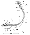
- FIG. 1 is a tire meridian cross-sectional view including a tire rotation axis in a normal state of the pneumatic tire 1 of the present embodiment.
- the normal state is a no-load state in which the tire is assembled on the normal rim RM and filled with the normal internal pressure.
- the dimensions and the like of each part of the tire are values measured in this normal state.
- the “regular rim” is a rim determined for each tire in the standard system including the standard on which the tire is based. For example, in the case of JATMA, “standard rim”, in the case of TRA, “Design Rim”, ETRTO If so, Me “Measuring Rim”.
- Regular internal pressure is the air pressure that each standard defines for each tire in the standard system including the standard on which the tire is based.
- JATMA “maximum air pressure”, for TRA, “TIRE LOAD LIMITS” The maximum value described in AT “VARIOUS” COLD “INFLATION” PRESSURES ”, or“ INFLATION PRESSURE ”in ETRTO.
- the pressure is uniformly set to 200 kPa in consideration of the actual use frequency.
- a pneumatic tire (hereinafter sometimes simply referred to as “tire”) 1 according to the present embodiment includes a carcass 6 that extends from a tread portion 2 to a bead core 5 of a bead portion 4 through a sidewall portion 3. And a belt layer 7 disposed on the outer side in the tire radial direction of the carcass 6 and on the inner side of the tread portion 2.
- a passenger car is shown.
- the carcass 6 is composed of, for example, one carcass ply 6A.
- This carcass ply 6A is provided with a series of folded portions 6b that are locked to the bead core 5 by folding the bead core 5 from the inner side to the outer side in the tire axial direction at both ends of the body portion 6a straddling the bead cores 5 and 5. It is.
- an organic fiber cord such as aromatic polyamide or rayon is adopted as the carcass cord.
- the carcass cord is arranged at an angle of 70 to 90 ° with respect to the tire equator C, for example.
- the carcass ply 6A is configured by covering a plurality of carcass cords with a topping rubber.
- a bead apex rubber 8 extending in a tapered shape from the bead core 5 toward the outer side in the tire radial direction is disposed between the main body portion 6a and the folded portion 6b.
- a tread rubber Tg that forms a ground contact surface On the outside of the carcass 6, a tread rubber Tg that forms a ground contact surface, a side wall rubber Sg that forms the outer surface of the side wall portion 3, a bead rubber Bg that forms the outer surface of the bead portion 4, and the like are disposed.
- an inner liner rubber Lg or the like for maintaining the tire internal pressure is disposed inside the carcass 6.
- the belt layer 7 includes two belt plies 7A and 7B in which the belt cords are inclined with respect to the tire equator C at an angle of, for example, 15 to 45 °, and the belt cords cross each other.
- the tire is overlapped in the tire radial direction.
- steel, aramid, rayon, or the like is suitably used for the belt cord.
- the belt plies 7A and 7B are configured by covering a plurality of belt cords with a topping rubber.
- the band layer 9 is disposed outside the belt layer 7 in the tire radial direction.
- the band layer 9 includes a band ply 9A in which an organic fiber band cord, in this example, a nylon cord is spirally wound at an angle of 10 degrees or less, preferably 5 degrees or less with respect to the tire circumferential direction.
- the pneumatic tire 1 has a sound control body 20 disposed on the inner surface of the tread portion 2.
- the sound control body 20 is made of, for example, a porous sponge material.
- the sponge material is a sponge-like porous structure, for example, a web in which animal fibers, plant fibers, or synthetic fibers are entangled and integrally connected in addition to a so-called sponge having open cells in which rubber or synthetic resin is foamed. It shall be included.
- the “porous structure” includes not only open cells but also those having closed cells.
- an open-cell sponge material made of polyurethane is used for the sound control body 20 of this example.
- the sponge material as described above reduces the sound (cavity resonance energy) by converting the vibration energy of the air that vibrates the surface or the inner porous portion into heat energy, thereby reducing the noise (running noise of the pneumatic tire 1). Reduce.
- the sponge material since the sponge material is easily deformed such as contraction and bending, it does not substantially affect the deformation of the tire during running. For this reason, it can prevent that steering stability deteriorates.
- the specific gravity of the sponge material is very small, it is possible to prevent deterioration of the weight balance of the tire.
- the sponge material is preferably an ether polyurethane sponge, ester polyurethane sponge, synthetic resin sponge such as polyethylene sponge, chloroprene rubber sponge (CR sponge), ethylene propylene rubber sponge (EDPM sponge), nitrile rubber sponge (NBR sponge), etc.
- a rubber sponge can be suitably used, and a polyurethane or polyethylene-based sponge including an ether polyurethane sponge is particularly preferable from the viewpoints of sound damping properties, light weight, foaming controllability, durability, and the like.
- the noise control body 20 has a long band shape having a bottom surface fixed to the inner cavity surface of the tread portion 2 and extends in the tire circumferential direction. At this time, the outer end portions in the circumferential direction can be abutted with each other to form a substantially annular shape, and the outer end portions may be spaced apart in the circumferential direction.
- the noise control body 20 has substantially the same cross-sectional shape at each position in the circumferential direction excluding the outer end portion.
- As the cross-sectional shape a flat and oblong shape having a small height with respect to the width in the tire axial direction is preferable in order to prevent falling or deformation during traveling.
- the concave groove 21 can increase the surface area of the sound control body 20 and absorb more resonance energy, and can improve heat dissipation and suppress the temperature rise of the sponge material.
- the glass transition temperature of the noise control body 20 is -55 ° C to -45 ° C.
- the hardness at normal temperature tends to decrease, which may affect the durability.
- the glass transition temperature exceeds ⁇ 45 ° C. the flexibility of the noise damper 20 at a low temperature is impaired, and the above-described reduction in running noise may be reduced.
- the glass transition temperature of the sound damper 20 is set in the range of ⁇ 55 ° C. to ⁇ 45 ° C., the flexibility of the sound damper at low temperatures is maintained. As a result, even when the vehicle is traveling in cold weather, the noise control body 20 effectively converts vibration energy of air into heat energy, and traveling noise is sufficiently reduced.
- the damping rubber body 30 is disposed inside the tread portion 2.
- the damping rubber body 30 is disposed between the carcass 6 and the belt layer 7.
- the damping rubber body 30 is made of a rubber different from the topping rubber included in the carcass ply 6A and the belt ply 7A.
- the width W1 of the damping rubber body 30 in the tire axial direction is 60 to 130% of the width W2 of the belt layer 7 in the tire axial direction.
- a more desirable width W1 of the damping rubber body 30 is 70 to 120% of the width W2 of the belt layer 7.
- Such a vibration-damping rubber body 30 suppresses vibrations of the carcass 6 and the belt layer 7 without causing an increase in weight of the pneumatic tire 1 and contributes to reduction of traveling noise particularly in the vicinity of 160 Hz. Note that the vibration damping rubber body 30 may be omitted when the noise suppression body 20 provides a sufficient running noise reduction effect.
- the thickness T1 of the damping rubber body 30 in the tire radial direction is preferably 0.3 mm or more.
- the vibration of the tread portion 2 is further effectively suppressed.
- the maximum thickness of the damping rubber body 30 in the radial direction of the tire to 4 to 20% of the maximum thickness of the tread portion 2, it is possible to achieve both suppression of traveling noise and stable driving performance of the pneumatic tire 1. It can be easily achieved.
- the relationship between the hardness H1 of the damping rubber body 30 and the hardness H2 of the tread rubber Tg disposed on the outer side in the tire radial direction of the belt layer 7 is preferably 0.5 ⁇ H1 / H2 ⁇ 1.0.
- “rubber hardness” is rubber hardness according to durometer type A in an environment of 23 ° C. in accordance with JIS-K6253.
- the vibration damping rubber body 30 having the hardness H1 further effectively suppresses the vibration of the tread portion 2 while ensuring the durability of the tread portion 2.
- the relationship between the hardness H1 of the damping rubber body 30 and the hardness H3 of the topping rubber included in the carcass ply 6A and the belt ply 7A is preferably 0.4 ⁇ H1 / H3 ⁇ 1.2.
- the vibration damping rubber body 30 having the hardness H1 further effectively suppresses the vibration of the tread portion 2 while ensuring the durability of the tread portion 2.
- More desirable hardness H1 of the vibration damping rubber body 30 is 30 ° to 73 °. With the vibration damping rubber body 30 having such hardness H1, it is possible to easily suppress running noise and improve steering stability performance while suppressing the manufacturing cost of the pneumatic tire 1.
- a more desirable hardness H2 of the more specific tread rubber Tg is 55 ° to 75 °. With the tread rubber Tg having such hardness H2, the rigidity of the tread portion 2 is optimized, and the steering stability performance can be improved.
- the puncture repair liquid is locally absorbed by the sound control body 20 during the puncture repair using the puncture repair liquid.
- Uniformity is the uniformity of the weight including the pneumatic tire 1, the noise control body 20, and the puncture repair liquid.
- the density of the noise control body 20 is desirably 10 kg / m 3 or more.
- the noise control body 20 having a density of 40 kg / m 3 or less can reduce running noise particularly in the vicinity of 250 Hz without increasing the weight of the pneumatic tire 1.
- the volume V1 of the sound control body 20 is preferably 0.4 to 30% of the total volume V2 of the tire lumen.
- the volume V1 of the sound control body 20 is an apparent total volume of the sound control body 20, and means a volume determined from an external shape including bubbles inside.
- the total volume V2 of the tire lumen is approximately calculated by the following equation in a normal state of no load in which a pneumatic tire is assembled on a normal rim and filled with a normal internal pressure.
- V2 A * ⁇ (Di-Dr) / 2 + Dr ⁇ * ⁇
- A is the cross-sectional area of the tire lumen obtained by CT scanning of the tire / rim assembly in the normal state
- Dr ⁇ is the maximum outer surface of the tire lumen in the normal state.
- the diameter, “Dr” is the rim diameter, and “ ⁇ ” is the circumference.
- volume V1 is less than 0.4% of the total volume V2, the vibration energy of the air may not be converted sufficiently.
- the volume V1 exceeds 30% of the total volume V2, the weight and manufacturing cost of the pneumatic tire 1 are increased.
- the uniformity performance after repair may be deteriorated.
- the tensile strength of the noise control body 20 is desirably 70 to 115 kPa. When the tensile strength of the noise damper 20 is less than 70 kPa, the durability of the noise damper 20 may be reduced. When the tensile strength of the sound control body 20 exceeds 115 kPa, when a foreign object such as a nail is stuck in the region including the sound control body 20 of the tread portion 2, the sound control body 20 is pulled by the foreign material and the inside of the tread portion 2 There is a risk of peeling from the cavity surface.
- the loss tangent tan ⁇ at 0 ° C. of the tread rubber Tg is desirably 0.4 or more. Thereby, the wet grip performance of the pneumatic tire 1 is improved. Therefore, for example, the travel noise can be further reduced by setting the volume of the groove formed on the ground contact surface of the tread portion 2 to be small.
- the loss tangent tan ⁇ at 70 ° C. of the tread rubber Tg is preferably 0.2 or less. Thereby, rolling resistance of the pneumatic tire 1 is suppressed, and deterioration of fuel efficiency performance due to the provision of the sound damping body 20 and the vibration damping rubber body 30 is suppressed.
- the tread rubber Tg desirably has a value of (1.4 ⁇ carbon black content (phr) + silica content (phr)) / sulfur content (phr) of 20 or more.
- abrasion resistance performance improves. Therefore, for example, the driving noise can be further reduced by setting a shallow groove formed on the ground contact surface of the tread portion 2. Further, even when uneven distribution occurs in the puncture repair liquid, the occurrence of uneven wear is suppressed.
- the present invention is not limited to the above-mentioned specific embodiment, and is carried out by changing it to various modes.
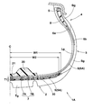
- FIG. 2 shows a pneumatic tire 1A which is another embodiment of the present invention.
- the pneumatic tire 1 ⁇ / b> A differs from the pneumatic tire 1 in that the damping rubber body 30 is disposed between the belt layer 7 and the band layer 9.
- the structure of the pneumatic tire 1 can be employ
- vibrations of the belt layer 7 and the band layer 9 are suppressed by the vibration damping rubber body 30, and thus vibrations of the tread portion 2 are suppressed.
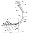
- FIG. 3 shows a pneumatic tire 1B which is still another embodiment of the present invention.
- the pneumatic tire 1B is different from the pneumatic tire 1 in that the damping rubber body 30 is disposed on the outer side of the band layer 9 in the tire radial direction.
- the structure of the pneumatic tire 1 may be employ
- the vibration suppression rubber body 30 suppresses vibrations of the band layer 9 and the tread rubber Tg, and consequently suppresses vibrations of the tread portion 2.
- a pneumatic tire of size 165 / 65R18 having the basic structure of FIG. 1 was prototyped based on the specifications of Table 1 and tested for noise performance in a low temperature environment.
- the specifications common to each example and comparative example are as follows.
- (1) Tread rubber and compounding are as follows.
- Natural rubber 15 (phr) SBR1 (bound styrene content: 28%, vinyl group content 60%, glass transition point -25 ° C., terminal modification): 45 (phr) SBR2 (bound styrene content: 35%, vinyl group content 45%, glass transition point -25 ° C., terminal modification): 25 (phr) BR (BR150B, Ube): 15 (phr) Carbon black N220: 5 (phr) Silica (VN3): 35 (phr) Silica (1115MP): 20 (phr) Silane coupling agent Si266: 4 (phr) Resin (Arizona Chemical SYLVARES SA85): 8 (phr) Oil: 4 (phr) Wax: 1.5 (phr) Anti-aging agent (6C): 3 (phr) Stearic acid: 3 (phr) Zinc oxide: 2 (phr) Sulfur: 2 (phr) Vulcan
- Each sample tire was mounted on a rim 18 ⁇ 7 JJ and brought into a test room where the room temperature was set to ⁇ 50 ° C.
- Each sample tire was run at a speed of 60 km / h on a drum having a replica road surface of 3.3 m in diameter under conditions of an internal pressure of 320 kPa and a load of 4.8 kN, 25 mm forward and 25 mm in height from the tread surface with contact with the ground.
- the sound pressure level (dB) at the separated position was measured with a microphone.
- the result is represented by an index with Example 1 as 100, and the larger the numerical value, the smaller the traveling noise and the better.
- pneumatic tires of Examples 23 to 27 were prototyped and tested for uniformity performance after puncture repair and noise performance in a low temperature environment.
- the test method is as follows.
- pneumatic tires of Examples 36 to 40 were prototyped and tested for uniformity performance after puncture repair and noise performance in a low temperature environment.
- the test method is as follows.
- Radial force variation was measured by the same method as above. A result is represented by the index
- Radial force variation was measured by the same method as above. A result is represented by the index
Landscapes
- Engineering & Computer Science (AREA)
- Mechanical Engineering (AREA)
- Chemical & Material Sciences (AREA)
- Health & Medical Sciences (AREA)
- Chemical Kinetics & Catalysis (AREA)
- Medicinal Chemistry (AREA)
- Polymers & Plastics (AREA)
- Organic Chemistry (AREA)
- Tires In General (AREA)
Priority Applications (6)
| Application Number | Priority Date | Filing Date | Title |
|---|---|---|---|
| US16/066,022 US20190375250A1 (en) | 2017-01-25 | 2017-12-12 | Pneumatic tire |
| JP2018513041A JP6524341B2 (ja) | 2017-01-25 | 2017-12-12 | 空気入りタイヤ |
| EP17894397.3A EP3406462B1 (en) | 2017-01-25 | 2017-12-12 | Pneumatic tire |
| CN201780003752.5A CN109070633B (zh) | 2017-01-25 | 2017-12-12 | 充气轮胎 |
| KR1020187012293A KR102000408B1 (ko) | 2017-01-25 | 2017-12-12 | 공기입 타이어 |
| US16/710,940 US20200114704A1 (en) | 2017-01-25 | 2019-12-11 | Pneumatic tire |
Applications Claiming Priority (2)
| Application Number | Priority Date | Filing Date | Title |
|---|---|---|---|
| JP2017-010922 | 2017-01-25 | ||
| JP2017010922 | 2017-01-25 |
Related Child Applications (2)
| Application Number | Title | Priority Date | Filing Date |
|---|---|---|---|
| US16/066,022 A-371-Of-International US20190375250A1 (en) | 2017-01-25 | 2017-12-12 | Pneumatic tire |
| US16/710,940 Continuation US20200114704A1 (en) | 2017-01-25 | 2019-12-11 | Pneumatic tire |
Publications (1)
| Publication Number | Publication Date |
|---|---|
| WO2018139084A1 true WO2018139084A1 (ja) | 2018-08-02 |
Family
ID=62978958
Family Applications (1)
| Application Number | Title | Priority Date | Filing Date |
|---|---|---|---|
| PCT/JP2017/044581 WO2018139084A1 (ja) | 2017-01-25 | 2017-12-12 | 空気入りタイヤ |
Country Status (6)
| Country | Link |
|---|---|
| US (2) | US20190375250A1 (zh) |
| EP (1) | EP3406462B1 (zh) |
| JP (2) | JP6524341B2 (zh) |
| KR (1) | KR102000408B1 (zh) |
| CN (2) | CN113619331A (zh) |
| WO (1) | WO2018139084A1 (zh) |
Cited By (1)
| Publication number | Priority date | Publication date | Assignee | Title |
|---|---|---|---|---|
| JP2019142503A (ja) * | 2017-01-25 | 2019-08-29 | 住友ゴム工業株式会社 | 空気入りタイヤ |
Families Citing this family (16)
| Publication number | Priority date | Publication date | Assignee | Title |
|---|---|---|---|---|
| US10836222B2 (en) * | 2018-10-26 | 2020-11-17 | Sensata Technologies, Inc. | Tire mounted sensors with controlled orientation and removal detection |
| CN110027368A (zh) * | 2019-04-16 | 2019-07-19 | 安徽佳通乘用子午线轮胎有限公司 | 一种低噪音充气轮胎组件 |
| JP7416957B2 (ja) * | 2019-12-26 | 2024-01-17 | コンパニー ゼネラール デ エタブリッスマン ミシュラン | 空気式タイヤ用の改良された音響発泡体の特性 |
| JP7476657B2 (ja) * | 2020-05-13 | 2024-05-01 | 住友ゴム工業株式会社 | タイヤ |
| WO2021256123A1 (ja) | 2020-06-15 | 2021-12-23 | 住友ゴム工業株式会社 | タイヤ |
| CN115697725A (zh) | 2020-06-15 | 2023-02-03 | 住友橡胶工业株式会社 | 轮胎 |
| CN115996853A (zh) | 2020-06-25 | 2023-04-21 | 住友橡胶工业株式会社 | 轮胎 |
| JP2022081097A (ja) | 2020-11-19 | 2022-05-31 | 住友ゴム工業株式会社 | タイヤ |
| FR3120815B1 (fr) | 2021-03-22 | 2023-02-24 | Michelin & Cie | Pneumatique comprenant une structure de rigidification endurante et permettant une bonne mise a plat |
| FR3120816B1 (fr) | 2021-03-22 | 2023-02-10 | Michelin & Cie | Pneumatique comprenant une decoupure circonferentielle et une structure de rigidification endurante et permettant une mise a plat optimisee |
| FR3120817B1 (fr) | 2021-03-22 | 2024-03-29 | Michelin & Cie | Pneumatique comprenant une structure de rigidification endurante |
| JP2022167781A (ja) | 2021-04-22 | 2022-11-04 | 住友ゴム工業株式会社 | 空気入りタイヤ |
| JP2023025806A (ja) | 2021-08-11 | 2023-02-24 | 住友ゴム工業株式会社 | タイヤ |
| FR3125253A1 (fr) | 2022-01-17 | 2023-01-20 | Compagnie Generale Des Etablissements Michelin | Assemblage a uniformite amelioree |
| FR3125249A1 (fr) | 2022-01-17 | 2023-01-20 | Compagnie Generale Des Etablissements Michelin | Procede de fabrication d’un assemblage a uniformite amelioree |
| JP2024060451A (ja) | 2022-10-19 | 2024-05-02 | 住友ゴム工業株式会社 | タイヤ |
Citations (6)
| Publication number | Priority date | Publication date | Assignee | Title |
|---|---|---|---|---|
| JP2004339424A (ja) * | 2003-05-19 | 2004-12-02 | Nippon Carbide Ind Co Inc | 発泡層形成用アクリル系共重合体水性組成物 |
| JP2009292461A (ja) | 2008-05-09 | 2009-12-17 | Yokohama Rubber Co Ltd:The | タイヤ騒音低減装置及びこれを装着した空気入りタイヤ |
| JP2014520175A (ja) * | 2011-06-01 | 2014-08-21 | コンパニー ゼネラール デ エタブリッスマン ミシュラン | トレッドが走行中の騒音を低減させる熱膨張性ゴム組成物を含むタイヤ |
| JP2015086344A (ja) * | 2013-11-01 | 2015-05-07 | 住友ゴム工業株式会社 | タイヤ吸音部材用ゴム組成物 |
| WO2016012945A1 (en) * | 2014-07-21 | 2016-01-28 | Bridgestone Corporation | Tyre comprising a foam material for sound absorption |
| JP2016210250A (ja) * | 2015-05-01 | 2016-12-15 | 株式会社ブリヂストン | タイヤ |
Family Cites Families (35)
| Publication number | Priority date | Publication date | Assignee | Title |
|---|---|---|---|---|
| JPS5773030A (en) * | 1980-09-20 | 1982-05-07 | Bridgestone Corp | Rubber composition for tire |
| FR2624063B1 (fr) * | 1987-12-07 | 1994-04-29 | Bridgestone Corp | Pneumatique de force |
| DE3830345C1 (zh) * | 1988-09-07 | 1989-11-02 | Teroson Gmbh, 6900 Heidelberg, De | |
| JPH02127101A (ja) | 1988-11-04 | 1990-05-15 | Sumitomo Rubber Ind Ltd | 空気入りタイヤ |
| EP0414892B1 (en) * | 1989-03-08 | 1993-09-01 | Bridgestone Corporation | Pneumatic radial tire |
| JP2868872B2 (ja) | 1990-09-14 | 1999-03-10 | 株式会社ブリヂストン | 発泡ゴム層をトレッドに有する空気入りタイヤ |
| JP2892904B2 (ja) * | 1993-04-16 | 1999-05-17 | 住友ゴム工業株式会社 | 空気入りタイヤ |
| JP2790982B2 (ja) * | 1994-11-15 | 1998-08-27 | 住友ゴム工業株式会社 | 空気入りラジアルタイヤ |
| BR9608507A (pt) * | 1995-05-12 | 1999-06-08 | Ici Plc | Processo para a preparação de espuma rigida de poliuretano processo para preparar uma espuma flexível de poliuretano sistema de reação e espuma flexível de poliuretano |
| US5770634A (en) | 1995-06-07 | 1998-06-23 | The Procter & Gamble Company | Foam materials for insulation, derived from high internal phase emulsions |
| CA2246025A1 (en) * | 1997-09-18 | 1999-03-18 | Giorgio Agostini | Heterogeneous silica carbon black-filled rubber compound |
| JP4125426B2 (ja) * | 1998-02-06 | 2008-07-30 | 三井化学ポリウレタン株式会社 | 低反発性ウレタンフォーム |
| JP4363697B2 (ja) | 1998-06-25 | 2009-11-11 | 株式会社ブリヂストン | タイヤトレッド用ゴム組成物及びそのゴム組成物を使用した空気入りタイヤ |
| EP1329420B1 (en) | 1999-12-27 | 2013-02-27 | Sumitomo Chemical Company, Limited | Aluminium hydroxide and tyre tread rubber composition and pneumatic tyre employing the aluminium hydroxide |
| AU2001246424A1 (en) | 2000-02-21 | 2001-08-27 | Pirelli Pneumatici S.P.A. | Motor vehicle tyre with an antiabrasive band capable of reducing its rolling resistance |
| BR0111256B1 (pt) | 2000-05-30 | 2010-12-14 | pneumÁtico para um veÍculo motorizado. | |
| US7220794B2 (en) | 2000-07-28 | 2007-05-22 | Sumitomo Rubber Industries, Ltd. | Rubber composition for tire treads and a pneumatic tire having a tread made of such composition |
| JP2003192832A (ja) * | 2001-12-26 | 2003-07-09 | Sumitomo Rubber Ind Ltd | トレッド用ゴム組成物 |
| DE60320985D1 (de) | 2002-06-05 | 2008-06-26 | Sumitomo Rubber Ind | Anordnung für luftreifen und felge, für die anordnung verwendeter schalldämpfungskörper und luftreifenlagerungsverfahren |
| JP2004285152A (ja) | 2003-03-20 | 2004-10-14 | Mitsui Takeda Chemicals Inc | 低反発性ウレタンフォームおよびその製造方法 |
| JP3787343B2 (ja) * | 2003-11-07 | 2006-06-21 | 住友ゴム工業株式会社 | 空気入りタイヤとリムとの組立体 |
| JP2006124578A (ja) * | 2004-10-29 | 2006-05-18 | Inoac Corp | ポリウレタンフォーム |
| EP1659004B1 (en) * | 2004-11-19 | 2012-02-01 | Sumitomo Rubber Industries, Ltd. | Assembly of pneumatic tire and rim and a noise damper used therein |
| JP4330550B2 (ja) * | 2005-04-28 | 2009-09-16 | 住友ゴム工業株式会社 | 空気入りタイヤとリムとの組立体 |
| JP2009161072A (ja) * | 2008-01-08 | 2009-07-23 | Toyo Tire & Rubber Co Ltd | 空気入りタイヤ |
| EP2537685A1 (en) | 2011-06-23 | 2012-12-26 | Compagnie Generale Des Etablissements Michelin | Tyre with improved tread |
| JP2013112062A (ja) | 2011-11-25 | 2013-06-10 | Sumitomo Rubber Ind Ltd | 制音体付空気入りタイヤ |
| WO2013140999A1 (ja) | 2012-03-23 | 2013-09-26 | 横浜ゴム株式会社 | 空気入りタイヤ |
| JP5536840B2 (ja) | 2012-09-07 | 2014-07-02 | 住友ゴム工業株式会社 | タイヤ用ゴム組成物、タイヤ部材、及び空気入りタイヤ |
| FR3010348B1 (fr) | 2013-09-06 | 2015-09-04 | Michelin & Cie | Pneumatique comportant une bande de roulement perfectionnee |
| JP6580595B2 (ja) | 2014-04-30 | 2019-09-25 | コンパニー ゼネラール デ エタブリッスマン ミシュラン | 抑制発泡体のストリップを含むタイヤ |
| JP6352748B2 (ja) * | 2014-09-25 | 2018-07-04 | 住友ゴム工業株式会社 | タイヤ |
| JP6436734B2 (ja) | 2014-11-14 | 2018-12-12 | 住友ゴム工業株式会社 | 空気入りタイヤ |
| US20190030954A1 (en) * | 2016-12-20 | 2019-01-31 | Sumitomo Rubber Industries, Ltd. | Pneumatic tire |
| KR102000408B1 (ko) | 2017-01-25 | 2019-07-15 | 스미토모 고무 고교 가부시키가이샤 | 공기입 타이어 |
-
2017
- 2017-12-12 KR KR1020187012293A patent/KR102000408B1/ko active IP Right Grant
- 2017-12-12 WO PCT/JP2017/044581 patent/WO2018139084A1/ja active Application Filing
- 2017-12-12 CN CN202111067104.0A patent/CN113619331A/zh not_active Withdrawn
- 2017-12-12 CN CN201780003752.5A patent/CN109070633B/zh active Active
- 2017-12-12 EP EP17894397.3A patent/EP3406462B1/en active Active
- 2017-12-12 US US16/066,022 patent/US20190375250A1/en not_active Abandoned
- 2017-12-12 JP JP2018513041A patent/JP6524341B2/ja active Active
-
2019
- 2019-04-26 JP JP2019086336A patent/JP7070498B2/ja active Active
- 2019-12-11 US US16/710,940 patent/US20200114704A1/en active Pending
Patent Citations (6)
| Publication number | Priority date | Publication date | Assignee | Title |
|---|---|---|---|---|
| JP2004339424A (ja) * | 2003-05-19 | 2004-12-02 | Nippon Carbide Ind Co Inc | 発泡層形成用アクリル系共重合体水性組成物 |
| JP2009292461A (ja) | 2008-05-09 | 2009-12-17 | Yokohama Rubber Co Ltd:The | タイヤ騒音低減装置及びこれを装着した空気入りタイヤ |
| JP2014520175A (ja) * | 2011-06-01 | 2014-08-21 | コンパニー ゼネラール デ エタブリッスマン ミシュラン | トレッドが走行中の騒音を低減させる熱膨張性ゴム組成物を含むタイヤ |
| JP2015086344A (ja) * | 2013-11-01 | 2015-05-07 | 住友ゴム工業株式会社 | タイヤ吸音部材用ゴム組成物 |
| WO2016012945A1 (en) * | 2014-07-21 | 2016-01-28 | Bridgestone Corporation | Tyre comprising a foam material for sound absorption |
| JP2016210250A (ja) * | 2015-05-01 | 2016-12-15 | 株式会社ブリヂストン | タイヤ |
Non-Patent Citations (1)
| Title |
|---|
| See also references of EP3406462A4 |
Cited By (2)
| Publication number | Priority date | Publication date | Assignee | Title |
|---|---|---|---|---|
| JP2019142503A (ja) * | 2017-01-25 | 2019-08-29 | 住友ゴム工業株式会社 | 空気入りタイヤ |
| JP7070498B2 (ja) | 2017-01-25 | 2022-05-18 | 住友ゴム工業株式会社 | 空気入りタイヤ |
Also Published As
| Publication number | Publication date |
|---|---|
| JP7070498B2 (ja) | 2022-05-18 |
| US20200114704A1 (en) | 2020-04-16 |
| EP3406462B1 (en) | 2020-09-02 |
| JP2019142503A (ja) | 2019-08-29 |
| KR20180116227A (ko) | 2018-10-24 |
| EP3406462A4 (en) | 2019-07-24 |
| EP3406462A1 (en) | 2018-11-28 |
| CN109070633A (zh) | 2018-12-21 |
| US20190375250A1 (en) | 2019-12-12 |
| KR102000408B1 (ko) | 2019-07-15 |
| CN113619331A (zh) | 2021-11-09 |
| CN109070633B (zh) | 2021-12-14 |
| JPWO2018139084A1 (ja) | 2019-01-31 |
| JP6524341B2 (ja) | 2019-06-05 |
Similar Documents
| Publication | Publication Date | Title |
|---|---|---|
| JP7070498B2 (ja) | 空気入りタイヤ | |
| JP6536744B2 (ja) | 空気入りタイヤ | |
| JP6481080B2 (ja) | 空気入りタイヤ | |
| JP6536743B2 (ja) | 空気入りタイヤ | |
| JP6939783B2 (ja) | 空気入りタイヤ | |
| JP2022065026A (ja) | 空気入りタイヤ |
Legal Events
| Date | Code | Title | Description |
|---|---|---|---|
| ENP | Entry into the national phase |
Ref document number: 2018513041 Country of ref document: JP Kind code of ref document: A |
|
| ENP | Entry into the national phase |
Ref document number: 20187012293 Country of ref document: KR Kind code of ref document: A |
|
| WWE | Wipo information: entry into national phase |
Ref document number: 2017894397 Country of ref document: EP |
|
| ENP | Entry into the national phase |
Ref document number: 2017894397 Country of ref document: EP Effective date: 20180822 |
|
| 121 | Ep: the epo has been informed by wipo that ep was designated in this application |
Ref document number: 17894397 Country of ref document: EP Kind code of ref document: A1 |
|
| NENP | Non-entry into the national phase |
Ref country code: DE |