WO2018135402A1 - 歩行転倒防止装置、の制御装置、制御方法、並びに、プログラム - Google Patents
歩行転倒防止装置、の制御装置、制御方法、並びに、プログラム Download PDFInfo
- Publication number
- WO2018135402A1 WO2018135402A1 PCT/JP2018/000606 JP2018000606W WO2018135402A1 WO 2018135402 A1 WO2018135402 A1 WO 2018135402A1 JP 2018000606 W JP2018000606 W JP 2018000606W WO 2018135402 A1 WO2018135402 A1 WO 2018135402A1
- Authority
- WO
- WIPO (PCT)
- Prior art keywords
- wire
- target value
- tension
- stiffness target
- ankle
- Prior art date
Links
- 238000000034 method Methods 0.000 title claims description 33
- 210000003423 ankle Anatomy 0.000 claims abstract description 508
- 230000033001 locomotion Effects 0.000 claims abstract description 73
- 210000000689 upper leg Anatomy 0.000 claims description 227
- 210000002414 leg Anatomy 0.000 claims description 161
- 210000002683 foot Anatomy 0.000 claims description 113
- 210000003127 knee Anatomy 0.000 claims description 97
- 230000002265 prevention Effects 0.000 claims description 52
- 208000027418 Wounds and injury Diseases 0.000 claims description 17
- 230000006378 damage Effects 0.000 claims description 16
- 208000014674 injury Diseases 0.000 claims description 15
- 230000007423 decrease Effects 0.000 claims description 2
- 238000005096 rolling process Methods 0.000 claims 1
- 210000001624 hip Anatomy 0.000 description 65
- 230000007246 mechanism Effects 0.000 description 31
- 230000008859 change Effects 0.000 description 21
- 230000003042 antagnostic effect Effects 0.000 description 17
- 230000004048 modification Effects 0.000 description 15
- 238000012986 modification Methods 0.000 description 15
- 238000010586 diagram Methods 0.000 description 14
- 210000000544 articulatio talocruralis Anatomy 0.000 description 10
- 210000001061 forehead Anatomy 0.000 description 9
- 230000000694 effects Effects 0.000 description 7
- 230000006870 function Effects 0.000 description 7
- 210000004394 hip joint Anatomy 0.000 description 7
- 230000002829 reductive effect Effects 0.000 description 6
- 230000002123 temporal effect Effects 0.000 description 6
- 238000013459 approach Methods 0.000 description 5
- 238000004364 calculation method Methods 0.000 description 5
- 238000004590 computer program Methods 0.000 description 5
- 230000008901 benefit Effects 0.000 description 4
- 239000004744 fabric Substances 0.000 description 4
- 239000002184 metal Substances 0.000 description 4
- 230000002441 reversible effect Effects 0.000 description 4
- 230000036962 time dependent Effects 0.000 description 4
- 125000002066 L-histidyl group Chemical group [H]N1C([H])=NC(C([H])([H])[C@](C(=O)[*])([H])N([H])[H])=C1[H] 0.000 description 3
- 208000018982 Leg injury Diseases 0.000 description 3
- 206010061225 Limb injury Diseases 0.000 description 3
- 230000009471 action Effects 0.000 description 2
- 238000005452 bending Methods 0.000 description 2
- 238000006243 chemical reaction Methods 0.000 description 2
- 230000003247 decreasing effect Effects 0.000 description 2
- 210000001503 joint Anatomy 0.000 description 2
- 238000012545 processing Methods 0.000 description 2
- 239000004065 semiconductor Substances 0.000 description 2
- 229920003002 synthetic resin Polymers 0.000 description 2
- 239000000057 synthetic resin Substances 0.000 description 2
- 238000004804 winding Methods 0.000 description 2
- 241000282412 Homo Species 0.000 description 1
- 230000005540 biological transmission Effects 0.000 description 1
- 230000000881 depressing effect Effects 0.000 description 1
- 238000013461 design Methods 0.000 description 1
- 230000005021 gait Effects 0.000 description 1
- 230000005283 ground state Effects 0.000 description 1
- 230000000670 limiting effect Effects 0.000 description 1
- 238000005259 measurement Methods 0.000 description 1
- 210000003205 muscle Anatomy 0.000 description 1
- 230000003287 optical effect Effects 0.000 description 1
- 230000009467 reduction Effects 0.000 description 1
Images


Classifications
-
- A—HUMAN NECESSITIES
- A61—MEDICAL OR VETERINARY SCIENCE; HYGIENE
- A61H—PHYSICAL THERAPY APPARATUS, e.g. DEVICES FOR LOCATING OR STIMULATING REFLEX POINTS IN THE BODY; ARTIFICIAL RESPIRATION; MASSAGE; BATHING DEVICES FOR SPECIAL THERAPEUTIC OR HYGIENIC PURPOSES OR SPECIFIC PARTS OF THE BODY
- A61H3/00—Appliances for aiding patients or disabled persons to walk about
-
- A—HUMAN NECESSITIES
- A61—MEDICAL OR VETERINARY SCIENCE; HYGIENE
- A61H—PHYSICAL THERAPY APPARATUS, e.g. DEVICES FOR LOCATING OR STIMULATING REFLEX POINTS IN THE BODY; ARTIFICIAL RESPIRATION; MASSAGE; BATHING DEVICES FOR SPECIAL THERAPEUTIC OR HYGIENIC PURPOSES OR SPECIFIC PARTS OF THE BODY
- A61H1/00—Apparatus for passive exercising; Vibrating apparatus; Chiropractic devices, e.g. body impacting devices, external devices for briefly extending or aligning unbroken bones
- A61H1/02—Stretching or bending or torsioning apparatus for exercising
- A61H1/0237—Stretching or bending or torsioning apparatus for exercising for the lower limbs
- A61H1/024—Knee
-
- A—HUMAN NECESSITIES
- A61—MEDICAL OR VETERINARY SCIENCE; HYGIENE
- A61H—PHYSICAL THERAPY APPARATUS, e.g. DEVICES FOR LOCATING OR STIMULATING REFLEX POINTS IN THE BODY; ARTIFICIAL RESPIRATION; MASSAGE; BATHING DEVICES FOR SPECIAL THERAPEUTIC OR HYGIENIC PURPOSES OR SPECIFIC PARTS OF THE BODY
- A61H1/00—Apparatus for passive exercising; Vibrating apparatus; Chiropractic devices, e.g. body impacting devices, external devices for briefly extending or aligning unbroken bones
- A61H1/02—Stretching or bending or torsioning apparatus for exercising
- A61H1/0237—Stretching or bending or torsioning apparatus for exercising for the lower limbs
- A61H1/0244—Hip
-
- A—HUMAN NECESSITIES
- A61—MEDICAL OR VETERINARY SCIENCE; HYGIENE
- A61H—PHYSICAL THERAPY APPARATUS, e.g. DEVICES FOR LOCATING OR STIMULATING REFLEX POINTS IN THE BODY; ARTIFICIAL RESPIRATION; MASSAGE; BATHING DEVICES FOR SPECIAL THERAPEUTIC OR HYGIENIC PURPOSES OR SPECIFIC PARTS OF THE BODY
- A61H1/00—Apparatus for passive exercising; Vibrating apparatus; Chiropractic devices, e.g. body impacting devices, external devices for briefly extending or aligning unbroken bones
- A61H1/02—Stretching or bending or torsioning apparatus for exercising
- A61H1/0237—Stretching or bending or torsioning apparatus for exercising for the lower limbs
- A61H1/0255—Both knee and hip of a patient, e.g. in supine or sitting position, the feet being moved together in a plane substantially parallel to the body-symmetrical plane
- A61H1/0262—Walking movement; Appliances for aiding disabled persons to walk
-
- A—HUMAN NECESSITIES
- A61—MEDICAL OR VETERINARY SCIENCE; HYGIENE
- A61H—PHYSICAL THERAPY APPARATUS, e.g. DEVICES FOR LOCATING OR STIMULATING REFLEX POINTS IN THE BODY; ARTIFICIAL RESPIRATION; MASSAGE; BATHING DEVICES FOR SPECIAL THERAPEUTIC OR HYGIENIC PURPOSES OR SPECIFIC PARTS OF THE BODY
- A61H1/00—Apparatus for passive exercising; Vibrating apparatus; Chiropractic devices, e.g. body impacting devices, external devices for briefly extending or aligning unbroken bones
- A61H1/02—Stretching or bending or torsioning apparatus for exercising
- A61H1/0237—Stretching or bending or torsioning apparatus for exercising for the lower limbs
- A61H1/0266—Foot
-
- A—HUMAN NECESSITIES
- A61—MEDICAL OR VETERINARY SCIENCE; HYGIENE
- A61H—PHYSICAL THERAPY APPARATUS, e.g. DEVICES FOR LOCATING OR STIMULATING REFLEX POINTS IN THE BODY; ARTIFICIAL RESPIRATION; MASSAGE; BATHING DEVICES FOR SPECIAL THERAPEUTIC OR HYGIENIC PURPOSES OR SPECIFIC PARTS OF THE BODY
- A61H3/00—Appliances for aiding patients or disabled persons to walk about
- A61H2003/007—Appliances for aiding patients or disabled persons to walk about secured to the patient, e.g. with belts
-
- A—HUMAN NECESSITIES
- A61—MEDICAL OR VETERINARY SCIENCE; HYGIENE
- A61H—PHYSICAL THERAPY APPARATUS, e.g. DEVICES FOR LOCATING OR STIMULATING REFLEX POINTS IN THE BODY; ARTIFICIAL RESPIRATION; MASSAGE; BATHING DEVICES FOR SPECIAL THERAPEUTIC OR HYGIENIC PURPOSES OR SPECIFIC PARTS OF THE BODY
- A61H2201/00—Characteristics of apparatus not provided for in the preceding codes
- A61H2201/01—Constructive details
- A61H2201/0173—Means for preventing injuries
-
- A—HUMAN NECESSITIES
- A61—MEDICAL OR VETERINARY SCIENCE; HYGIENE
- A61H—PHYSICAL THERAPY APPARATUS, e.g. DEVICES FOR LOCATING OR STIMULATING REFLEX POINTS IN THE BODY; ARTIFICIAL RESPIRATION; MASSAGE; BATHING DEVICES FOR SPECIAL THERAPEUTIC OR HYGIENIC PURPOSES OR SPECIFIC PARTS OF THE BODY
- A61H2201/00—Characteristics of apparatus not provided for in the preceding codes
- A61H2201/12—Driving means
- A61H2201/1207—Driving means with electric or magnetic drive
- A61H2201/1215—Rotary drive
-
- A—HUMAN NECESSITIES
- A61—MEDICAL OR VETERINARY SCIENCE; HYGIENE
- A61H—PHYSICAL THERAPY APPARATUS, e.g. DEVICES FOR LOCATING OR STIMULATING REFLEX POINTS IN THE BODY; ARTIFICIAL RESPIRATION; MASSAGE; BATHING DEVICES FOR SPECIAL THERAPEUTIC OR HYGIENIC PURPOSES OR SPECIFIC PARTS OF THE BODY
- A61H2201/00—Characteristics of apparatus not provided for in the preceding codes
- A61H2201/14—Special force transmission means, i.e. between the driving means and the interface with the user
- A61H2201/1481—Special movement conversion means
- A61H2201/149—Special movement conversion means rotation-linear or vice versa
-
- A—HUMAN NECESSITIES
- A61—MEDICAL OR VETERINARY SCIENCE; HYGIENE
- A61H—PHYSICAL THERAPY APPARATUS, e.g. DEVICES FOR LOCATING OR STIMULATING REFLEX POINTS IN THE BODY; ARTIFICIAL RESPIRATION; MASSAGE; BATHING DEVICES FOR SPECIAL THERAPEUTIC OR HYGIENIC PURPOSES OR SPECIFIC PARTS OF THE BODY
- A61H2201/00—Characteristics of apparatus not provided for in the preceding codes
- A61H2201/16—Physical interface with patient
- A61H2201/1602—Physical interface with patient kind of interface, e.g. head rest, knee support or lumbar support
- A61H2201/1628—Pelvis
- A61H2201/163—Pelvis holding means therefor
-
- A—HUMAN NECESSITIES
- A61—MEDICAL OR VETERINARY SCIENCE; HYGIENE
- A61H—PHYSICAL THERAPY APPARATUS, e.g. DEVICES FOR LOCATING OR STIMULATING REFLEX POINTS IN THE BODY; ARTIFICIAL RESPIRATION; MASSAGE; BATHING DEVICES FOR SPECIAL THERAPEUTIC OR HYGIENIC PURPOSES OR SPECIFIC PARTS OF THE BODY
- A61H2201/00—Characteristics of apparatus not provided for in the preceding codes
- A61H2201/16—Physical interface with patient
- A61H2201/1602—Physical interface with patient kind of interface, e.g. head rest, knee support or lumbar support
- A61H2201/164—Feet or leg, e.g. pedal
- A61H2201/1642—Holding means therefor
-
- A—HUMAN NECESSITIES
- A61—MEDICAL OR VETERINARY SCIENCE; HYGIENE
- A61H—PHYSICAL THERAPY APPARATUS, e.g. DEVICES FOR LOCATING OR STIMULATING REFLEX POINTS IN THE BODY; ARTIFICIAL RESPIRATION; MASSAGE; BATHING DEVICES FOR SPECIAL THERAPEUTIC OR HYGIENIC PURPOSES OR SPECIFIC PARTS OF THE BODY
- A61H2201/00—Characteristics of apparatus not provided for in the preceding codes
- A61H2201/16—Physical interface with patient
- A61H2201/1602—Physical interface with patient kind of interface, e.g. head rest, knee support or lumbar support
- A61H2201/165—Wearable interfaces
- A61H2201/1652—Harness
-
- A—HUMAN NECESSITIES
- A61—MEDICAL OR VETERINARY SCIENCE; HYGIENE
- A61H—PHYSICAL THERAPY APPARATUS, e.g. DEVICES FOR LOCATING OR STIMULATING REFLEX POINTS IN THE BODY; ARTIFICIAL RESPIRATION; MASSAGE; BATHING DEVICES FOR SPECIAL THERAPEUTIC OR HYGIENIC PURPOSES OR SPECIFIC PARTS OF THE BODY
- A61H2201/00—Characteristics of apparatus not provided for in the preceding codes
- A61H2201/50—Control means thereof
- A61H2201/5002—Means for controlling a set of similar massage devices acting in sequence at different locations on a patient
-
- A—HUMAN NECESSITIES
- A61—MEDICAL OR VETERINARY SCIENCE; HYGIENE
- A61H—PHYSICAL THERAPY APPARATUS, e.g. DEVICES FOR LOCATING OR STIMULATING REFLEX POINTS IN THE BODY; ARTIFICIAL RESPIRATION; MASSAGE; BATHING DEVICES FOR SPECIAL THERAPEUTIC OR HYGIENIC PURPOSES OR SPECIFIC PARTS OF THE BODY
- A61H2201/00—Characteristics of apparatus not provided for in the preceding codes
- A61H2201/50—Control means thereof
- A61H2201/5007—Control means thereof computer controlled
-
- A—HUMAN NECESSITIES
- A61—MEDICAL OR VETERINARY SCIENCE; HYGIENE
- A61H—PHYSICAL THERAPY APPARATUS, e.g. DEVICES FOR LOCATING OR STIMULATING REFLEX POINTS IN THE BODY; ARTIFICIAL RESPIRATION; MASSAGE; BATHING DEVICES FOR SPECIAL THERAPEUTIC OR HYGIENIC PURPOSES OR SPECIFIC PARTS OF THE BODY
- A61H2201/00—Characteristics of apparatus not provided for in the preceding codes
- A61H2201/50—Control means thereof
- A61H2201/5058—Sensors or detectors
- A61H2201/5061—Force sensors
-
- A—HUMAN NECESSITIES
- A61—MEDICAL OR VETERINARY SCIENCE; HYGIENE
- A61H—PHYSICAL THERAPY APPARATUS, e.g. DEVICES FOR LOCATING OR STIMULATING REFLEX POINTS IN THE BODY; ARTIFICIAL RESPIRATION; MASSAGE; BATHING DEVICES FOR SPECIAL THERAPEUTIC OR HYGIENIC PURPOSES OR SPECIFIC PARTS OF THE BODY
- A61H2201/00—Characteristics of apparatus not provided for in the preceding codes
- A61H2201/50—Control means thereof
- A61H2201/5058—Sensors or detectors
- A61H2201/5071—Pressure sensors
-
- A—HUMAN NECESSITIES
- A61—MEDICAL OR VETERINARY SCIENCE; HYGIENE
- A61H—PHYSICAL THERAPY APPARATUS, e.g. DEVICES FOR LOCATING OR STIMULATING REFLEX POINTS IN THE BODY; ARTIFICIAL RESPIRATION; MASSAGE; BATHING DEVICES FOR SPECIAL THERAPEUTIC OR HYGIENIC PURPOSES OR SPECIFIC PARTS OF THE BODY
- A61H2230/00—Measuring physical parameters of the user
Definitions
- the present disclosure relates to a walking and falling prevention device, a control device, a control method, and a program that are worn by a user and prevent the user from falling in the left-right direction when walking.
- the non-limiting exemplary embodiment of the present disclosure provides a walking and tipping prevention device, a control device, a control method, and a program that can prevent a user who falls while walking to the left and to the right.
- a walking fall prevention device includes a left ankle upper belt fixed to a user's left ankle upper portion, a right ankle upper belt fixed to the user's right ankle upper portion, and the user A left ankle lower belt fixed to the left lower ankle of the user, a right lower ankle belt fixed to the lower right ankle of the user, and the right upper ankle belt and the right lower ankle belt.
- Wire, upper left ankle belt and lower left ankle A fourth wire connected to the belt, and at least a portion of the third wire is disposed along a right side surface of the left ankle, and at least a portion of the fourth wire is a left side surface of the left ankle.
- a first tension controller that controls the tension of the first wire
- a second tension controller that controls the tension of the second wire
- a tension of the third wire is a first tension controller that controls the tension of the third wire.
- a third tension controller a fourth tension controller that controls the tension of the fourth wire; an acquirer that acquires user information of the user and walking information indicating the walking motion of the user; and a controller;
- the controller includes: a first stiffness target value for the first wire; a second stiffness target value for the second wire; and a third stiffness value for the third wire based on the user information and the walking information path. 3 rigidity target value, the fourth wire A fourth stiffness target value is determined, and the controller causes the first tension controller to control the tension of the first wire using the first stiffness target value, and the controller controls the first stiffness target value.
- the second tension controller controls the tension of the second wire, and the controller uses the third stiffness target value to cause the third tension controller to The tension of the third wire is controlled, and the controller causes the fourth tension controller to control the tension of the fourth wire using the fourth stiffness target value, and the first wire
- the tension control of the second wire and the tension control of the second wire are performed simultaneously, and the tension control of the third wire and the tension control of the fourth wire are performed simultaneously.
- the walking and falling prevention device includes a waist belt fixed to the user's waist, a left upper knee belt fixed to the upper knee of the left leg of the user, and the right leg of the user.
- a right upper knee belt fixed to the upper knee a fifth wire connected to the waist belt and the right upper belt, and a sixth wire connected to the waist belt and the right upper belt.
- a wire, a seventh wire connected to the waist belt and the left upper knee belt, an eighth wire connected to the waist belt and the left upper knee belt, and less of the fifth wire Are arranged along the right side of the right thigh of the user, and at least a part of the sixth wire is arranged along the left side of the right thigh, and less of the seventh wire.
- a fifth tension controller for controlling the tension of the fifth wire;
- a sixth tension controller that controls tension;
- a seventh tension controller that controls tension of the seventh wire;
- an eighth tension controller that controls tension of the eighth wire; and the user
- a controller for acquiring the user information and the walking information indicating the walking motion of the user, and the controller is configured to control the fifth of the fifth wire based on the user information and the walking information.
- a stiffness target value a sixth stiffness target value of the sixth wire, a seventh stiffness target value of the seventh wire, and an eighth stiffness target value of the eighth wire;
- the fifth tension controller The tension of the ear is controlled, and the controller uses the sixth rigidity target value to cause the sixth tension controller to control the tension of the sixth wire, and the controller controls the seventh rigidity.
- the seventh tension controller controls the tension of the seventh wire
- the controller uses the eighth stiffness target value to control the eighth tension controller.
- the tension control of the eighth wire is controlled, the tension control of the fifth wire and the tension control of the sixth wire are performed simultaneously, and the tension control of the seventh wire and the tension control of the eighth wire are performed simultaneously. Done.
- the computer-readable recording medium includes a non-volatile recording medium such as a CD-ROM (Compact Disc-Read Only Memory).
- positioning of an ankle upper belt, an ankle lower belt, and a wire as a 1st example of the assist wear of the walking fall prevention apparatus in embodiment of this indication.
- positioning of assist pants and a wire as a 2nd example of assist wear
- positioning of an ankle upper belt, an ankle lower belt, assist pants, and a wire as a 3rd example of assist wear Explanatory drawing which shows the structure of the walking fall prevention apparatus in embodiment of this indication.
- movement of the motor control part in embodiment of this indication The figure which shows operation
- summary of the assist system in the modification of embodiment of this indication The figure which shows arrangement
- the figure which shows an example of the torque of the thigh and the ankle joint in the modification of embodiment of this indication Explanatory drawing which shows the structure of the walking fall prevention apparatus in the modification of embodiment of this indication.
- the left upper ankle belt fixed to the upper left ankle of the user, the right upper ankle belt fixed to the upper right ankle of the user, and the left of the user A left ankle lower belt fixed to the lower ankle of the user; a right lower ankle belt fixed to the lower right ankle of the user; the right upper ankle belt and the right lower ankle belt; A first wire, a second wire connected to the right ankle upper belt and the right ankle lower belt (7a), and at least a portion of the first wire is on the right side of the right ankle.
- the fourth wire to be tied and at least a part of the third wire are disposed along the right side surface of the left ankle, and at least a part of the fourth wire is along the left side surface of the left ankle.
- a first tension controller disposed and controlling the tension of the first wire; a second tension controller controlling the tension of the second wire; and a third tension controlling the tension of the third wire.
- a controller, a fourth tension controller that controls the tension of the fourth wire an acquisition unit that acquires user information of the user and walking information indicating the walking motion of the user, and a controller; And a controller based on the user information and the walking information path, a first stiffness target value of the first wire, a second stiffness target value of the second wire, and a third stiffness target of the third wire.
- fourth stiffness of the fourth wire A value is determined, and the controller causes the first tension controller to control the tension of the first wire using the first stiffness target value, and the controller controls the second stiffness target value.
- the second tension controller is used to control the tension of the second wire, and the controller uses the third stiffness target value to cause the third tension controller to control the third tension.
- the tension of the wire is controlled, and the controller uses the fourth stiffness target value to cause the fourth tension controller to control the tension of the fourth wire, and controls the tension of the first wire.
- a walking and tipping prevention device in which tension control of the second wire is performed simultaneously, and tension control of the third wire and tension control of the fourth wire are performed simultaneously.
- the tension of each wire is controlled using a stiffness target value based on user information and walking information. As a result, it is possible to prevent the user who is walking from falling to the left and to the right.
- the first tension controller includes a first rotation shaft to which the first wire is coupled, and the first tension shaft is controlled by rotation control of the first rotation shaft.
- a first motor that controls the tension of the second wire, and the second tension controller has a second rotating shaft to which the second wire is coupled, and by rotation control of the second rotating shaft,
- a second motor for controlling a tension of the second wire, and the third tension controller includes a third rotating shaft to which the third wire is coupled, and the third rotating shaft is rotated.
- the fourth tension controller includes a third motor that controls the tension of the third wire by control, and the fourth tension controller includes a fourth rotating shaft to which the fourth wire is coupled, and the fourth rotation.
- a fourth motor for controlling the tension of the fourth wire by controlling the rotation of the shaft The controller instructs the first motor for rotation control of the first rotation shaft, instructs the second motor for rotation control of the second rotation shaft, and controls the third motor.
- the walking and tipping prevention device according to the first aspect, wherein an instruction for rotation control of the third rotation shaft is given to a motor and an instruction for rotation control of the fourth rotation shaft is given to the fourth motor is provided. To do.
- each tension controller is a motor that controls the tension of the corresponding wire.
- the motor generates a tension proportional to the amount of change in the length of the corresponding wire in the same manner as the spring, and can prevent the user from falling in the left-right direction while walking.
- the walking and falling prevention device includes a waist belt that is fixed to the waist of the user, a left upper knee belt that is fixed to an upper knee of the left leg of the user, A right upper belt fixed to the upper knee of the right leg of the user, a fifth wire connected to the waist belt and the right upper belt, and connected to the waist belt and the right upper belt
- a sixth wire connected to the waist belt and the left upper knee belt, an eighth wire connected to the waist belt and the left upper knee belt, 5 is arranged on the right side of the right thigh of the user, and at least a part of the sixth wire is arranged on the left side of the right thigh.
- At least a part of the eighth wire is disposed on the left side surface of the left thigh, and controls a fifth tension controller for controlling the tension of the fifth wire, and controls the tension of the sixth wire.
- the vessel is based on the user information and the walking information, the fifth rigidity target value of the fifth wire, the sixth rigidity target value of the sixth wire, the seventh rigidity target value of the seventh wire, An eighth stiffness target value of an eighth wire is determined, and the controller causes the fifth tension controller to control the tension of the fifth wire using the fifth stiffness target value, and the control Using the sixth stiffness target value, the sixth tension controller
- the tension of the sixth wire is controlled, and the controller uses the seventh stiffness target value to cause the seventh tension controller to control the tension of the seventh wire, and the controller
- the eighth tension controller is used to control the tension of the eighth wire using the eighth stiffness target value, and the tension control of the fifth wire and the tension control of the sixth wire are performed simultaneously.
- the walking and falling prevention device according to the first aspect is provided in which the tension control of the seventh wire and the tension control of the eighth wire are performed simultaneously.
- the tension of each wire is controlled using a stiffness target value based on user information and walking information. As a result, it is possible to prevent the user who is walking from falling to the left and to the right.
- the fifth tension controller includes a fifth rotation shaft to which the fifth wire is coupled, and the fifth tension controller is configured to control the fifth rotation shaft by controlling the rotation of the fifth rotation shaft.
- a fifth motor for controlling the tension of the wire, and the sixth tension controller has a sixth rotating shaft to which the sixth wire is coupled, and by controlling the rotation of the sixth rotating shaft,
- a sixth motor for controlling a tension of the sixth wire wherein the seventh tension controller has a seventh rotation shaft to which the seventh wire is coupled, and the rotation of the seventh rotation shaft;
- the eighth motor includes a seventh motor that controls the tension of the seventh wire, and the eighth tension controller includes an eighth rotating shaft to which the eighth wire is coupled, and the eighth rotation.
- An eighth motor for controlling the tension of the eighth wire by controlling the rotation of the shaft The control unit instructs the fifth tension controller to control the rotation of the fifth rotating shaft, and instructs the sixth tension controller to control the rotation of the sixth rotating shaft.
- a prevention device is provided.
- each tension controller is a motor that controls the tension of the corresponding wire.
- the motor generates a tension proportional to the amount of change in the length of the corresponding wire in the same manner as the spring, and can prevent the user from falling to the left and falling to the right while walking.
- a waist belt fixed to a user's waist a left upper knee belt fixed to an upper knee of the user's left leg, and an upper knee of the user's right leg
- a right upper knee belt fixed to the belt a fifth wire connected to the waist belt and the right upper knee belt, a sixth wire connected to the waist belt and the right upper belt, A seventh wire connected to the waist belt and the left upper knee belt, an eighth wire connected to the waist belt and the left upper knee belt, and at least a part of the fifth wire Is disposed along the right side of the user's right thigh, and at least a portion of the sixth wire is disposed along the left side of the right thigh, and at least a portion of the seventh wire.
- At least a part of the wire is disposed along the left side surface of the left thigh, and a fifth tension controller that controls the tension of the fifth wire and a sixth tension controller that controls the tension of the sixth wire.
- Tension controller a seventh tension controller for controlling the tension of the seventh wire, an eighth tension controller for controlling the tension of the eighth wire, user information of the user, and the user And a controller for acquiring walking information indicating the walking motion of the fifth wire, the controller based on the user information and the walking information, the fifth stiffness target value of the fifth wire, the first 6th stiffness target value of 6 wires, 7th stiffness target value of the 7th wire, 8th stiffness target value of the 8th wire are determined, and the controller uses the 5th stiffness target value.
- the fifth tension controller includes the tension of the fifth wire.
- the controller uses the sixth stiffness target value to cause the sixth tension controller to control the tension of the sixth wire, and the controller uses the seventh stiffness target value.
- the seventh tension controller controls the tension of the seventh wire, and the controller uses the eighth stiffness target value to cause the eighth tension controller to control the eighth wire.
- Tension control is performed, the tension control of the fifth wire and the tension control of the sixth wire are performed simultaneously, and the tension control of the seventh wire and the tension control of the eighth wire are performed simultaneously.
- a prevention device is provided.
- the tension of each wire is controlled using a stiffness target value based on user information and walking information. As a result, it is possible to prevent the user who is walking from falling to the left and to the right.
- the fifth tension controller includes a fifth rotation shaft to which the fifth wire is coupled, and the fifth tension controller is configured to control the fifth rotation shaft by controlling the rotation of the fifth rotation shaft.
- a fifth motor for controlling the tension of the wire, and the sixth tension controller has a sixth rotating shaft to which the sixth wire is coupled, and by controlling the rotation of the sixth rotating shaft,
- a sixth motor for controlling a tension of the sixth wire wherein the seventh tension controller has a seventh rotation shaft to which the seventh wire is coupled, and the rotation of the seventh rotation shaft;
- the eighth motor includes a seventh motor that controls the tension of the seventh wire, and the eighth tension controller includes an eighth rotating shaft to which the eighth wire is coupled, and the eighth rotation.
- An eighth motor for controlling the tension of the eighth wire by controlling the rotation of the shaft The control unit instructs the fifth tension controller to control the rotation of the fifth rotating shaft, and instructs the sixth tension controller to control the rotation of the sixth rotating shaft.
- a prevention device is provided.
- each tension controller is a motor that controls the tension of the corresponding wire.
- the motor generates a tension proportional to the amount of change in the length of the corresponding wire in the same manner as the spring, and can prevent the user from falling to the left and falling to the right while walking.
- the first stiffness target value is equal to the second stiffness target value
- the third stiffness target value is equal to the fourth stiffness target value.
- the walking fall prevention device according to the third or fourth aspect, wherein the value is equal to the sixth stiffness target value and the seventh stiffness target value is equal to the eighth stiffness target value.
- control unit (i) performs an instruction for rotation control of the first rotation shaft based on the force generated in the first wire, and the second An instruction for rotation control of the second rotating shaft is performed based on the force generated in the wire, and an instruction for rotation control of the third rotating shaft is performed based on the force generated in the third wire.
- An instruction for rotation control is performed, based on the force generated in the sixth wire, an instruction for rotation control of the sixth rotation shaft is performed, and based on the force generated in the seventh wire, An instruction for rotation control of the seventh rotation shaft is performed, and the eighth wire Or (ii) for controlling the rotation of the first rotating shaft based on the length of the first wire.
- the acquisition unit includes at least one of information related to the user's age, information related to the presence or absence of injury or damage to the user's legs, and information indicating the degree of fatigue of the user.
- the controller acquires the first stiffness target value, the second stiffness target value, the third stiffness target value, the fourth stiffness target value, The fifth stiffness target value, the sixth stiffness target value, the seventh stiffness target value, and the eighth stiffness target value are changed so as to increase, and if there is an injury or an obstacle in the leg, the first stiffness Target value, second stiffness target value, third stiffness target value, fourth stiffness target value, fifth stiffness target value, sixth stiffness target value, seventh stiffness target value, eighth Change the stiffness target value so that it increases, and the degree of fatigue is large.
- the first stiffness target value, the second stiffness target value, the third stiffness target value, the fourth stiffness target value, the fifth stiffness target value, the sixth stiffness target value, the seventh stiffness The walking fall prevention device according to the third or fourth aspect, in which the target value and the eighth stiffness target value are changed so as to increase, is provided.
- the fall prevention effect suitable for each user can be exhibited.
- the walking information includes a user's fatigue level over time based on a first fatigue point and a second fatigue point, and the second fatigue point is determined by the user's fatigue point.
- the first fatigue point is determined when the number of steps taken during the predetermined time decreases as the walking time elapses, and the second fatigue degree
- the points increase when walking time increases, the time fatigue increases as the first fatigue point increases, and the time fatigue increases as the second fatigue point increases, the controller If it is determined that the degree of fatigue over time is greater than a threshold, the first stiffness target value, the second stiffness target value, the third stiffness target value, the fourth stiffness target value, and the fifth stiffness Target value, above Sixth stiffness target value, the seventh stiffness target value, to provide a walking overturning prevention device according to embodiments of the third or 4 to increase the eighth stiffness target value.
- the rigidity is further increased and the fall prevention effect is enhanced. be able to.
- the acquisition device includes a walking information acquisition device that acquires the walking information, and the controller is based on the walking information acquired by the walking information acquisition device.
- the walking fall prevention device according to the third or fourth aspect, which controls timing for changing the eighth stiffness target value.
- the walking information is the user's walking cycle information
- the walking cycle information includes time information for contacting the right foot and the walking surface in one walking cycle of the user's right foot.
- the eleventh stiffness target value is the first stiffness target value when the right foot is in contact with the grounding surface
- the twelfth stiffness target value is when the right foot is in contact with the grounding surface.
- the fifteenth stiffness target value is the fifth stiffness target value when the right foot is in contact with the ground contact surface
- the sixteenth stiffness target value is the right stiffness of the right foot.
- the sixth stiffness target value when it is in contact with the ground plane is the first stiffness target value when the right foot is not in contact with the ground plane, and the twenty-second stiffness value.
- the stiffness target value is that the right foot is not in contact with the ground contact surface.
- the 25th stiffness target value is the fifth stiffness target value when the right foot is not in contact with the ground contact surface, and the 26th stiffness target value is the right stiffness of the right foot.
- the sixth stiffness target value when not in contact with the ground plane, and the control unit first, based on the walking cycle information, immediately before the right foot touches the walking surface in the current walking cycle.
- the stiffness target value is changed from the 21st stiffness target value to the 11th stiffness target value, the second stiffness target value is changed from the 22nd stiffness target value to the twelfth stiffness target value, and the fifth stiffness target value is changed.
- the walking overturn prevention device according to the eleventh aspect, wherein the 25th stiffness target value is changed from the 25th stiffness target value to the 15th stiffness target value, and the sixth stiffness target value is changed from the 26th stiffness target value to the 16th stiffness target value. I will provide a.
- the walking information of the user is the walking cycle information of the user
- the rigidity control unit is predicted based on the walking cycle information of the user.
- the walking and tipping preventing device according to the eleventh aspect is provided, wherein the rigidity value is controlled to be larger than the rigidity value before a certain predetermined period in the swing leg period before the predetermined time.
- the rigidity transmitted to the user can be increased immediately before the grounding, and a fall prevention effect can be achieved.
- the control unit determines the first stiffness target value based on the walking cycle information in a state where the right foot in the current walking cycle is not in contact with the walking surface.
- the eleventh stiffness target value is changed to the twenty-first stiffness target value
- the second stiffness target value is changed from the twelfth stiffness target value to the twenty-second stiffness target value
- the fifth stiffness target value is changed to the fifteenth stiffness target value.
- the walking / falling prevention device according to the twelfth aspect is provided in which the value is changed from the value to the 25th stiffness target value and the sixth stiffness target value is changed from the 16th stiffness target value to the 26th stiffness target value.
- the fourteenth aspect it is possible to prevent the movement of the leg joint from being inhibited by reducing the rigidity transmitted to the user when the user's foot is away from the ground contact surface.
- the user's leg when the user's leg is in contact with the grounding surface, it is possible to increase the rigidity in the left-right direction immediately before the grounding, thereby providing a fall prevention effect.
- a control device for an apparatus including a plurality of belts and a plurality of wires, wherein the plurality of belts are fixed on a left ankle upper part of a user's left ankle.
- a belt, a right upper ankle belt fixed to the user's right ankle upper portion, a left ankle lower belt fixed to the user's left ankle lower portion, and a user's right ankle lower portion A right lower ankle belt, wherein the plurality of wires include a first wire coupled to the right upper ankle belt and the right lower ankle belt, the right upper ankle belt, and the lower ankle belt.
- the portion is disposed along the right side surface of the left ankle, at least a portion of the fourth wire is disposed along the left side surface of the left ankle, and the control device controls the tension of the first wire.
- the controller controls the tension of the second wire, the controller uses the third stiffness target value to cause the third tension controller to control the tension of the third wire, and The controller uses the fourth stiffness target value to cause the fourth tension controller to control the tension of the fourth wire, thereby controlling the tension of the first wire and the tension of the second wire.
- the controller uses the third stiffness target value to cause the third tension controller to control the tension of the third wire, and the controller uses the fourth stiffness target value to cause the fourth tension controller to control the tension of the fourth wire, thereby controlling the tension of the first wire and the tension of the second wire.
- Force control provides a control device that takes place simultaneously.
- the tension of each wire is controlled using a stiffness target value based on user information and walking information. As a result, it is possible to prevent the user who is walking from falling to the left and to the right.
- a control device for an apparatus including a plurality of belts and a plurality of wires, wherein the plurality of belts are fixed to a user's waist, and the user's waist A left upper knee belt fixed to the upper knee of the left leg and a right upper knee belt fixed to the upper knee of the right leg of the user, wherein the plurality of wires are the waist belt and the right upper knee A fifth wire connected to the belt, a sixth wire connected to the waist belt and the right upper belt, and a seventh wire connected to the waist belt and the left upper belt.
- the control device includes: a fifth tension controller that controls a tension of the fifth wire; a sixth tension controller that controls a tension of the sixth wire; and a tension of the seventh wire.
- the controller causes the eighth tension controller to control the tension of the eighth wire, and
- a control device is provided in which the tension control of the wire and the tension control of the sixth wire are performed simultaneously, and the tension control of the seventh wire and the tension control of the eighth wire are performed simultaneously.
- the tension of each wire is controlled using a stiffness target value based on user information and walking information. As a result, it is possible to prevent the user who is walking from falling to the left and to the right.
- a control method for an apparatus including a plurality of belts and a plurality of wires, wherein the plurality of belts are fixed on a left ankle upper part of a user's left ankle.
- a belt, a right upper ankle belt fixed to the user's right ankle upper portion, a left ankle lower belt fixed to the user's left ankle lower portion, and a user's right ankle lower portion A right lower ankle belt, wherein the plurality of wires include a first wire coupled to the right upper ankle belt and the right lower ankle belt, the right upper ankle belt, and the lower ankle belt.
- a portion is disposed along a right side surface of the left ankle, at least a part of the fourth wire is disposed along a left side surface of the left ankle, and the control method includes: Walking information indicating walking motion is acquired, and based on the user information and the walking information, a first stiffness target value of the first wire, a second stiffness target value of the second wire, the third A third stiffness target value of the wire and a fourth stiffness target value of the fourth wire are determined, the tension of the first wire is controlled using the first stiffness target value, and the second stiffness target value is determined.
- the tension of the third wire is controlled using the third stiffness target value
- the tension of the third wire is controlled using the fourth stiffness target value
- the tension of the fourth wire is controlled
- the tension of each wire is controlled using a stiffness target value based on user information and walking information. As a result, it is possible to prevent the user who is walking from falling to the left and to the right.
- a control method for an apparatus including a plurality of belts and a plurality of wires, wherein the plurality of belts include a waist belt fixed to a user's waist, and the user's waist.
- an eighth wire connected to the waist belt and the left upper knee belt, and at least a part of the fifth wire is disposed on the right side of the right thigh of the user, At least part of the wire At least part of the seventh wire is disposed on the right side of the left thigh of the user, and at least part of the eighth wire is disposed on the left side of the left thigh.
- the control method acquires the user information of the user and walking information indicating the walking motion of the user, and based on the user information and the walking information, the fifth rigidity target value of the fifth wire, A sixth stiffness target value of the sixth wire, a seventh stiffness target value of the seventh wire, an eighth stiffness target value of the eighth wire are determined, and the fifth stiffness target value is used to determine the 5, control the tension of the sixth wire using the sixth stiffness target value, and control the tension of the seventh wire using the seventh stiffness target value. , Using the eighth stiffness target value, Tension control of the fifth wire and tension control of the sixth wire are performed simultaneously, and tension control of the seventh wire and tension control of the eighth wire are performed simultaneously. Provide a control method.
- the tension of each wire is controlled using a stiffness target value based on user information and walking information. As a result, it is possible to prevent the user who is walking from falling to the left and to the right.
- a program for causing a computer to execute a control method for an apparatus including a plurality of belts and a plurality of wires, wherein the plurality of belts are fixed to an upper left ankle of a user.
- a left ankle upper belt, a right ankle upper belt fixed to the user's right ankle upper portion, a left ankle lower belt fixed to the user's left ankle lower portion, and the user's right ankle belt A right ankle lower belt fixed to an ankle lower portion, wherein the plurality of wires include a first wire coupled to the right ankle upper belt and the right ankle lower belt; and the right ankle belt.
- a fourth wire to be tied wherein at least a portion of the first wire is disposed along a right side of the right ankle, and at least a portion of the second wire is along a left side of the right ankle.
- At least a portion of the third wire is disposed along a right side surface of the left ankle, and at least a portion of the fourth wire is disposed along a left side surface of the left ankle.
- the method acquires user information of the user and walking information indicating the walking motion of the user, and based on the user information and the walking information, the first stiffness target value of the first wire, the second A second stiffness target value of the wire, a third stiffness target value of the third wire, a fourth stiffness target value of the fourth wire are determined, and the first wire is determined using the first stiffness target value.
- the tension of each wire is controlled using a stiffness target value based on user information and walking information. As a result, it is possible to prevent the user who is walking from falling to the left and to the right.
- a belt, a left upper knee belt fixed to the upper knee of the user's left leg, and a right upper knee belt fixed to the upper knee of the user's right leg, and the plurality of wires include the waist A fifth wire connected to the belt and the right upper knee belt, a sixth wire connected to the waist belt and the right upper knee belt, and connected to the waist belt and the left upper knee belt
- the sixth At least part of the wire is disposed on the left side of the right thigh
- at least part of the seventh wire is disposed on the right side of the user's left thigh
- at least part of the eighth wire is It is arranged on the left side of the left thigh
- the control method acquires user information of the user and walking information indicating the walking motion of the user, and based on the user information and the walking information, the fifth Determining a fifth
- the tension of each wire is controlled using a stiffness target value based on user information and walking information. As a result, it is possible to prevent the user who is walking from falling to the left and to the right.
- FIGS. 1A to 1C are diagrams illustrating three examples of a case where a user wears the assist mechanism 2 of the assist system 1 as an example of the walking fall prevention device according to the embodiment of the present disclosure and uses the assist system 1.
- FIG. 2 is an explanatory diagram illustrating an overview of the assist system 1 of FIG. 1C as an example of a walking and falling prevention device according to an embodiment of the present disclosure.
- FIG. 3A is an explanatory diagram for explaining the attachment configuration of the outer wire 15 and the ankle wire 11 of the assist system 1.
- 3B and 3C are a front view and a side view for explaining the configuration of the motor 14 and the like of the example of the tension applying mechanism 70 of the assist system 1.
- the assist system 1 is a device that prevents the user 100 from falling while walking, and includes an assist mechanism 2 worn by the user 100 and a control device 3 that controls the operation of the assist mechanism 2.
- the assist mechanism 2 includes an assist wear 72 attached to at least a part of the lower half of the user 100, a plurality of wires, and a tension applying mechanism 70.
- a plurality of wires are arranged in the assist wear 72, and a tension is applied to the plurality of wires by the tension applying mechanism 70 to give rigidity to prevent the user 100 from wearing the assist wear 72. it can.
- reference numeral 11 when referring to an ankle wire to be described later, reference numeral 11 is used, and when referring to an individual ankle wire, individual reference numerals 11e, 11f, 11g, and 11h are used.
- reference numeral 15 is used when referring to an ankle outer wire to be described later, and individual reference numerals 15e, 15f, 15g, and 15h are used when indicating an individual ankle outer wire.
- thigh wire 10 motors 13 and 14
- lower end ankle outer wire attachment portion 16 upper end ankle outer wire attachment portion 17, lower end ankle wire attachment portion 18, and lower end thigh wire attachment portion 19, which will be described later.
- the assist wear 72 is detachably attached to the user 100, and three examples are shown below.
- the assist wear 72 As a first example of the assist wear 72, as shown in FIG. 1A, it can be composed of assist ankle bands 2b and 2c. As a second example of the assist wear 72, as shown in FIG. As shown in FIG. 1C, the third example of the assist wear 72 can be configured by both the assist ankle bands 2b and 2c of the first example and the assist pants 2a of the second example. In the following description, the first example will be described, and then the second example will be described.
- the assist ankle bands 2b and 2c of the first example include left and right upper ankle belts 6b and 6a that are detachably fixed to the upper ankles of the left and right legs of the user 100, respectively.
- the left and right ankle lower belts for example, left and right ankle lower belts, for example, heel belts 7b and 7a, which are detachably fixed to the heel.
- the left and right ankle upper belts 6b and 6a are made of cloth belts, for example.
- the left and right heel belts 7b and 7a are constituted by, for example, cloth belts.
- the left and right upper ankle belts 6 b and 6 a and the left and right heel belts 7 b and 7 a are detachably attached to the left and right ankles of the user 100.
- the tension applying mechanism 70 is provided on the waist belt 4 that is detachably attached to the waist of the user 100, for example.
- the ankle wire 11 is arranged as a wire in the assist wear 72 in the first example.
- the ankle wire 11 is composed of, for example, metal first to fourth ankle wires 11e, 11f, 11g, and 11h that have flexibility but do not expand and contract in the longitudinal direction.
- the upper ends of the first to fourth ankle wires 11e, 11f, 11g, and 11h are fixed to the respective tension applying mechanisms 70, and the first to fourth ankle wires 11e, 11e, 11f, 11g, and 11h each move as a pseudo spring to change the rigidity of the thigh.
- the lower ends of the first to fourth ankle wires 11e, 11f, 11g, and 11h are fixed to the left and right heel belts 7b and 7a after passing through the ankle upper belts 6b and 6a.
- the lower ends of the first to fourth ankle wires 11e, 11f, 11g, and 11h are fixed to the lower end ankle wire attachment portions 18e, 18f, 18g, and 18h of the left and right heel belts 7b and 7a.
- the tensioning mechanism may be called a tension controller.
- the first ankle wire 11e is disposed along the longitudinal direction of the right leg of the user 100 at a portion corresponding to the right side surface of the right ankle of the user 100, and the lower ankle outer wire attachment portion 16e of the right ankle upper belt 6a.
- the lower end is connected to the lower end ankle wire attaching portion 18e of the right heel belt 7a.
- the second ankle wire 11f is arranged along the longitudinal direction of the right leg of the user 100 at a portion corresponding to the left side surface of the right ankle of the user 100, and passes through the lower ankle outer wire attachment portion 16f of the right ankle upper belt 6a. And the lower end is connected with the lower end ankle wire attaching part 18f of the right heel belt 7a.
- the third ankle wire 11g is arranged along the longitudinal direction of the left leg of the user 100 at a portion corresponding to the right side surface of the left ankle of the user 100, and passes through the lower ankle outer wire attaching portion 16g of the left ankle upper belt 6b. And the lower end is connected with the lower end ankle wire attaching part 18g of the left heel belt 7b.
- the fourth ankle wire 11h is disposed along the longitudinal direction of the left leg of the user 100 at a portion corresponding to the left side surface of the left ankle of the user 100, and passes through the lower ankle outer wire attachment portion 16h of the left ankle upper belt 6b. And the lower end is connected with the lower end ankle wire attaching part 18h of the left heel belt 7b.
- each ankle wire 11 is not fixed only by passing through the lower end ankle outer wire attaching portion 16 of the ankle upper belts 6a and 6b.
- the lower end of the ankle outer wire 15 is fixed to the lower end ankle outer wire attachment portion 16, and each ankle between the lower end ankle outer wire attachment portion 16 and the lower end ankle wire attachment portion 18. Since the tensile force from the wire 11 acts, each ankle wire 11 is substantially connected to the lower end ankle outer wire attachment portion 16.
- the respective tension applying mechanisms 70 are driven under the control of the control device 3 to pull or loosen the first to fourth ankle wires 11e, 11f, 11g, and 11h, respectively, to thereby Tensile forces applied to the four ankle wires 11e, 11f, 11g, and 11h are individually adjusted independently, and the assist wear 72 imparts rigidity to prevent the user 100 from falling.
- the tension applying mechanism 70 can be constituted by, for example, a motor. As an example, an example of a motor will be described.
- the tension applying mechanism 70 is configured by, for example, a motor 14 whose rotation drive is controlled by the control device 3.
- FIG. 3B and FIG. 3C are views showing attachment portions of the motor 14 and the ankle wire 11.
- An encoder 51 is attached to the motor 14, and the rotation angle of the rotation shaft 14 a of each motor 14 can be detected by the encoder 51 and sent to the control device 3.
- a pulley 50 is fixed to the rotating shaft 14 a that rotates forward and backward of each motor 14, and the upper end of each ankle wire 11 exposed above the upper end of each ankle outer wire 15 is fixed to the pulley 50. Later, the ankle wire 11 is wound.
- the ankle wire 11 is drawn out or wound up by 2 ⁇ r p when the pulley 50 rotates once by forward and reverse rotation of the motor 14. Therefore, the distal end portion of the ankle wire 11 is moved by 2.pi.r p.
- the gear is omitted, but the pulley 50 may be attached to the rotating shaft 14a of the motor 14 via the gear.
- the driving of the motor 14 is controlled by the control device 3. Therefore, under the control of the control device 3, the length of each ankle wire 11 is adjusted by forward and reverse rotation of the rotating shaft 14a of the motor 14, and a tensile force is applied to each ankle wire 11 or the application is released.
- an ankle outer member such as a metal or a synthetic resin is formed between the waist belt 4 and the upper ankle belts 6a and 6b in a flexible and long hollow cylindrical shape such as a metal or a synthetic resin.
- the wires 15 are arranged and fixed, and the respective ankle wires 11 are inserted into the ankle outer wires 15 so as to be relatively movable. By configuring in this way, it is possible to prevent the tensile force of each ankle wire 11 from acting between the waist belt 4 and the ankle upper belts 6b and 6a.
- the upper ends of the long and cylindrical ankle outer wires 15e, 15f, 15g, and 15h are fixed to the upper end ankle outer wire attachment portions 17e, 17f, 17g, and 17h of the waist belt 4.
- the lower ends of the ankle outer wires 15e, 15f, 15g, 15h are fixed to the lower ankle outer wire attachment portions 16e, 16f, 16g, 16h of the ankle upper belts 6a, 6b.
- the distance between the waist belt 4 and the ankle upper belts 6a and 6b is fixed by the ankle outer wires 15, and even if a tensile force acts on each ankle wire 11 inserted through each ankle outer wire 15, It does not act between the waist belt 4 and the ankle upper belts 6a and 6b, and the gap between the waist belt 4 and the ankle upper belts 6a and 6b can be ignored. In other words, the tension when the motor 14 pulls the ankle wire 11 acts between the outer wire attachment portion 16 and the ankle wire end attachment portion 18.
- the lower ankle outer wire attachment portion 16e of the ankle upper belt 6a is located at a portion corresponding to the right side surface of the right ankle.
- the lower end ankle outer wire attachment portion 16f of the ankle upper belt 6a is located at a portion corresponding to the left side surface of the right ankle.
- the lower end ankle outer wire attachment portion 16g of the ankle upper belt 6b is located at a portion corresponding to the right side surface of the left ankle.
- the lower end ankle outer wire attachment portion 16h of the ankle upper belt 6b is located at a portion corresponding to the left side surface of the left ankle.
- the lower end ankle wire attaching portion 18e of the heel belt 7a is located at a portion corresponding to the right side surface of the right ankle.
- the lower end ankle wire attaching portion 18f of the heel belt 7a is located at a portion corresponding to the left side surface of the right ankle.
- the lower end ankle wire attaching portion 18g of the heel belt 7b is located at a portion corresponding to the right side surface of the left ankle.
- the lower end ankle wire attaching portion 18h of the heel belt 7b is located at a portion corresponding to the left side surface of the left ankle.
- the ankle wires 11e and 11f on the outer side and the inner side of the right leg are in an antagonistic relationship
- the ankle wires 11g and 11h on the inner side and the outer side of the left leg are in an antagonistic relationship. Therefore, the length of the ankle wire 11e and the length of the ankle wire 11f are adjusted independently by rotating the motors 14e and 14f independently forward and backward under the control of the control device 3, respectively.
- the ankle wires 11e and 11f on the outside and inside of the pair of right legs of the antagonistic relationship are driven to pull each other, rigidity can be imparted to the ankle of the right leg.
- the motors 14g and 14h are independently rotated forward and reversely under the control of the control device 3 to independently adjust the length of the ankle wire 11g and the length of the ankle wire 11h, respectively. .
- the ankle wires 11g and 11h on the inside and outside of the pair of left legs in the antagonistic relationship are driven to pull each other, rigidity can be imparted to the ankle of the left leg.
- the motor 14 rotates based on the rotation angle of each motor 14 detected by the encoder 51 and winds each ankle wire 11 around the pulley 50 via the rotation shaft 14 a.
- the upper end of each ankle wire 11 is pulled upward, and a tensile force is applied to each ankle wire 11.
- the heel belts 7a and 7b are pulled upward by the ankle wires 11 so as to approach the ankle upper belts 6a and 6b.
- rigidity is transmitted to the left side of the ankle and the right side of the ankle at the same time, and both the left and right sides of the ankle are pulled and held by the elastic body (spring) at the same time. It can be demonstrated.
- FIG. 1B and FIG. 1C a case where the assist wear 72 is constituted by the assist pants 2a will be described as a second example.
- the assist mechanism 2 is composed of assist wear 72, which is assist pants 2a, a plurality of thigh wires 10, and a tension applying mechanism 70.
- the assist pants 2a includes an assist pant body 2d that the user 100 detachably attaches to the lower body, a waist belt 4, and left and right upper knee belts 5b and 5a.
- the waist belt 4 is composed of, for example, a cloth belt fixed to the upper end edge of the assist pants main body 2d, and restrains the waist of the user 100 in a detachable manner.
- the left and right upper knee belts 5b and 5a are constituted by, for example, cloth belts fixed to the left and right lower end edges (hems) of the assist pant body 2d, and detachably restrain the left and right knee portions of the user 100. .
- each thigh wire 10 is located along the longitudinal direction of the left leg or right leg of the user 100 between the waist belt 4 of the assist pants body 2d and the left and right upper knee belts 5b, 5a.
- the thigh wire 10 is composed of, for example, metal first to fourth thigh wires 10e, 10f, 10g, and 10h that have flexibility but do not expand and contract in the longitudinal direction.
- first to fourth thigh wires 10e, 10f, 10g, and 10h are fixed to the respective tension applying mechanisms 70, and the first to fourth thigh wires 10e, 10e, 10f, 10g, and 10h each move as a spring in a pseudo manner to change the rigidity of the thigh.
- the thigh wire 10e is disposed in a portion of the assist pant body 2d corresponding to the outer side of the right thigh (right thigh right side) of the user 100, and the lower end is the waist belt 4 and the knee of the right leg. It connects with the lower end thigh wire attaching part 19e of the upper belt 5a.
- the thigh wire 10f is disposed in a portion of the assist pant body 2d corresponding to the inner side of the right thigh (the left side of the right thigh) of the user 100, and the lower end is the lower end of the waist belt 4 and the upper knee belt 5a of the right leg. It is connected to the thigh wire attaching portion 19f.
- the thigh wire 10g is arranged in a portion corresponding to the inner side of the left thigh (the left thigh right side surface) of the user 100 in the assist pant main body 2d, and the lower end is the lower end of the waist belt 4 and the upper knee belt 5b of the left leg. It is connected to the thigh wire attaching portion 19g.
- the thigh wire 10h is disposed in a portion of the assist pant main body 2d corresponding to the outer left thigh (left thigh left side) of the user 100, and the lower end is the lower end of the waist belt 4 and the upper knee belt 5b of the left leg. It is connected to the thigh wire attachment portion 19h.
- the thigh wires 10e and 10f on the outside and inside of the right leg are in an antagonistic relationship
- the thigh wires 10g and 10h on the inside and outside of the left leg are in an antagonistic relationship. Therefore, the lengths of the thigh wire 10e on the outer side and the inner side and the length of the thigh wire 10f are independently adjusted by independently rotating the motors 13e and 13f in the forward and reverse directions under the control of the control device 3, respectively. .
- the outer and inner thigh wires 10e and 10f of the pair of right legs in the antagonistic relationship are driven to pull each other, rigidity can be imparted to the thigh of the right leg.
- the lengths of the thigh wire 10g and the thigh wire 10h on the inner side and the outer side are independently adjusted by rotating the motors 13g and 13h independently forward and backward under the control of the control device 3, respectively.
- the thigh wires 10g and 10h on the inside and outside of a pair of left legs in an antagonistic relationship are driven to pull each other, rigidity can be imparted to the thighs of the left leg.
- the respective tension applying mechanisms 70 are driven under the control of the control device 3 to pull or loosen the first to fourth thigh wires 10e, 10f, 10g, and 10h, respectively, thereby to Tensile forces to be applied to the four thigh wires 10e, 10f, 10g, and 10h are individually adjusted independently, and the assist wear 72 provides the rigidity of the user 100 to the fall of the user 100, respectively.
- Each tension applying mechanism 70 is provided in the waist belt 4, for example.
- Each tension applying mechanism 70 is configured by, for example, a thigh wire driving motor 13 whose rotational driving is controlled by the control device 3, similarly to the motor 14 shown in FIGS. 3B and 3C. Since the motor 13 and the attachment part of the wire 10 are the same as the attachment part of the motor 14 and the wire 11 shown in FIGS. 3B and 3C, the corresponding reference numerals are indicated in parentheses in FIGS. 3B and 3C. The description is omitted.
- the upper ends of the thigh wires 10e, 10f, 10g, and 10h are connected to pulleys 50 fixed to the rotation shafts of the motors 13e, 13f, 13g, and 13h. Therefore, under the control of the control device 3, based on the rotation angle of each motor 13 detected by the encoder 51, the rotation of the rotation shafts of the motors 13 e, 13 f, 13 g, and 13 h causes the waist belt 4 and left and right
- the lengths of the thigh wires 10e, 10f, 10g, and 10h between the above-knee belts 5b and 5a are adjusted, respectively, and a tensile force is applied to each thigh wire 10 or the application is released.
- the motor 13 rotates and winds each thigh wire 10 around the pulley 50 via the rotating shaft, whereby the upper end of each thigh wire 10 is pulled upward, and each thigh wire is pulled up. Tensile force is applied to 10. Then, the above-knee belts 5 b and 5 a are pulled upward so that the thigh wires 10 approach the waist belt 4. As a result, rigidity is transmitted to the left side of the thigh and the right side of the thigh at the same time, and the left and right sides of the thigh are both pulled and held by the elastic body (spring) at the same time. It can be demonstrated.
- FIG. 4A is a block diagram illustrating the control device 3 according to the embodiment of the present disclosure, the tension applying mechanism 70 of the assist mechanism 2 to be controlled, and the input interface unit 200 on the input side with respect to the control device 3. Based on this FIG. 4A, the schematic structure of the control apparatus 3 is demonstrated first.
- the input interface unit may be called an acquirer.
- the control device 3 controls the operation of the assist mechanism 2.
- the control device 3 includes an input interface unit 200 and a stiffness control unit 124.
- the input interface unit 200 acquires information on the ground contact surface 90 on which the user 100 walks, that is, ground contact state information, as an example of walking information.
- the stiffness control unit 124 controls each set of tension applying mechanisms 70 that should control the stiffness to be transmitted to the user's site, and the set of tensions.
- tensile_strength of each wire contained in one set of wires corresponding to the provision mechanism 70 is controlled simultaneously. Thereby, the rigidity transmitted to each of the right side surface and the left side surface of the left ankle, which is the user's site corresponding to the first set of wires, is changed at the same time, and the user site corresponding to the second set of wires.
- the rigidity transmitted to the right side and the left side of the right ankle is simultaneously changed and transmitted to the right side and the left side of the left thigh, which is the user's part corresponding to the third set of wires.
- the rigidity is simultaneously changed, and the rigidity transmitted to each of the right side surface and the left side surface of the right thigh, which is the user's site corresponding to the fourth set of wires, is simultaneously changed.
- the ankle wire 11e on the outside (right side) of the set of right legs and the ankle wire 11f on the inside (left side) of the right leg correspond to the right ankle of the user, and the inside (right side) of the set of left legs.
- the ankle wire 11g and the ankle wire 11h on the outside (left side) of the left leg correspond to the left ankle of the user, and the thigh wire 10e on the outside (right side) of the pair of right legs and the inside (left side) of the right leg.
- the thigh wire 10f corresponds to the user's right thigh
- the thigh wire 10g on the inner side (right side) of the pair of left legs and the thigh wire 10h on the outer side (left side) of the left leg correspond to the user's left thigh.
- FIG. 4B is a block diagram showing a specific configuration when the tension applying mechanism 70 is the motor 13 or 14.
- the information to be handled is a difference between information on the ankle, information on the thigh, information on both the ankle and the thigh, Since the basic operation of giving or releasing the rigidity to the corresponding part of the user is the same, the description will mainly be made based on information on the ankle or thigh.
- control device 3 is configured by a general microcomputer as an example.
- the control device 3 includes a control program 40 that is a controller having a first stiffness target value output unit 24 that functions as an example of a stiffness control unit, and an input interface unit 200 that acquires user information regarding the user 100 itself. Yes. Therefore, by operating the motor 13 or 14 by the control device 3, the tension of the wire 11 or 10 connected to the motor 13 or 14 changes. Like the spring, the tension is generated so that the tension of the wire 10 or 11 is proportional to the amount of change in length, so that the two points connected by the thigh wire 10 or the ankle wire 11 as described above. Stiffness can be generated in the thigh or ankle sandwiched between the two.
- the first stiffness target value output unit 24 simultaneously controls the length of one pair of thigh wires 10 or one set of ankle wires 11 by drivingly controlling one set of motors 13 or one set of motors 14. By doing so, the rigidity transmitted to the left and right sides of the left thigh, right thigh, left ankle or right ankle can be changed simultaneously.
- the first stiffness target value output unit 24 controls the one set of motors 14e and 14f based on the user information and the walking information regarding the user 100 acquired by the input interface unit 200, respectively. By individually controlling the tension of the ankle wire 11e and the ankle wire 11f, the rigidity transmitted to the left side surface and the right side surface of the right ankle is simultaneously changed. In addition, the first stiffness target value output unit 24 controls each of the motors 14g and 14h at the same time, and independently controls the respective tensions of the ankle wire 11g and the ankle wire 11h. Thus, the rigidity transmitted to the left side surface and the right side surface of the left ankle is controlled to change simultaneously.
- the first stiffness target value output unit 24 controls each set of motors 13e and 13f based on the walking information on the ground contact surface 90 acquired by the input interface unit 200, and sets one set. By independently controlling the respective tensions of the thigh wire 10e and the thigh wire 10f, the rigidity transmitted to the left side surface and the right side surface of the right thigh is simultaneously changed. In addition, the first stiffness target value output unit 24 simultaneously controls each of the pair of motors 13g and 13h and independently controls each of the pair of thigh wires 10g and thigh wires 10h. Thus, the rigidity transmitted to the left side surface and the right side surface of the left thigh is controlled to change simultaneously.
- the input interface unit 200 includes at least a user information input unit 12 that functions as an example of a user information acquisition unit, and foot sensors 8a and 8b as an example of a walking information acquisition device that acquires walking information of the walking motion of the user 100. It functions as an example of the information acquisition unit.
- the input interface unit 200 includes an input / output IF 41, a user information input unit 12, and foot sensors 8 a and 8 b that acquire walking information related to a walking state when the user 100 walks. .
- the input / output IF (interface) 41 is configured to include, for example, a D / A board, an A / D board, a counter board, and the like connected to an expansion slot such as a PCI bus of a microcomputer.
- the control device 3 sends a control signal to the motor 13 or 14 via an input / output IF 41 as an example of an output unit.
- the control device 3 receives signals from the foot sensors 8a and 8b and information from the user information input unit 12 as input units via the input / output IF 41, respectively.
- the control device 3 includes a walking cycle estimation unit 20, an assist strength determination unit 21, a timing determination unit 23, a first stiffness target value output unit 24, and a torque target value setting unit 25.
- the motor setting unit 26, the motor control unit 27, and the second stiffness target value output unit 28 are configured.
- the user information acquisition unit may be called a user information acquisition unit.
- the user information input unit 12 is provided in the assist pants 2a or the assist ankle bands 2b and 2c, or is configured independently of them and used by the user 100, for example, a portable device such as a touch panel or a smartphone. Etc. Prior to use, the user 100 uses the user information input unit 12 to determine the user's 100 age, degree of disability (eg, leg injury condition), and / or degree of fatigue (ie, information on fatigue state). An example of user information is input to the assist strength determination unit 21.
- FIG. 4C is a diagram showing display and operation on the touch panel 12a as an example of the user information input unit 12.
- the user 100 first selects one of the age option buttons on the touch panel 12a and presses the “Next” button. That is, the user 100 inputs information regarding age.
- buttons of “Energetic”, “A little tired”, and “Unlike to walk” is selected. That is, the user 100 inputs information indicating the degree of fatigue.
- buttons that are not selected are hatched, and the selected buttons are displayed as white, so that the age is the “60s” button, the walking problem is the “nothing special” button, and the fatigue level is The button “I am a little tired” is selected.
- the user information input unit 12 outputs all the information of the options selected in this way to the assist strength determination unit 21 via the input / output IF 41 as user information.
- the first stiffness target value output unit 24 uses the information on the user 100 acquired from the user information input unit 12 via the assist strength determination unit 21 and the walking information from the foot sensors 8a and 8b. Based on this, the rigidity transmitted to the left side surface and the right side surface of the corresponding part of the user is changed.
- the foot sensors 8a and 8b are provided in the assist pants 2a. Specifically, the foot sensors 8a and 8b are provided on the heel belts 7a and 7b or the back surface of the socks including the heel belts 7a and 7b.
- the foot sensors 8a and 8b respectively detect the ground contact state of both feet of the user 100 as walking information that is information related to the walking state, and the ground state information is an example of walking information to the walking cycle estimation unit 20 via the input / output IF 41. Output as.
- FIG. 5 is a diagram showing an example of the arrangement of a large number of foot sensors 8b provided on the back surface of the foot such as the socks of the left foot.
- a large number of foot sensors 8a are also arranged on the back surface of the foot such as the right foot sock, as in the case of the left foot in FIG.
- the foot sensors 8a and 8b 26 pieces from L1 to L26 are arranged only by the left foot, and 26 pieces from R1 to R26 are arranged on the right foot similarly to the left foot (not shown).
- the foot sensors 8a and 8b When the portions where the sensors 8a and 8b are disposed are in contact with the ground plane 90, the foot sensors 8a and 8b output ON signals, respectively, while the portions where the foot sensors 8a and 8b are disposed are in contact with each other. If it is not in contact with the ground 90, an OFF signal is output from each of the foot sensors 8a and 8b.
- All the identification information of the 52 foot sensors 8a and 8b and the ON / OFF information of the 52 foot sensors 8a and 8b are collectively referred to as ground contact state information.
- the grounding state information includes identification information of the foot sensors 8a and 8b and ON / OFF information of the foot sensors 8a and 8b. Therefore, for example, information on whether or not the footpad is in contact with the grounding surface 90. Can
- the walking cycle estimation unit 20 estimates walking cycle information based on walking information from foot sensors 8a and 8b as an example of a walking information acquisition device. Specifically, the ground contact state information of the left and right feet from the foot sensors 8a and 8b is input to the walking cycle estimation unit 20 via the input / output IF 41, respectively. The walking cycle estimation unit 20 obtains the ground contact state information from the foot sensors 8a and 8b and the time information acquired from the internal timer and one of the foot sensors 8a and 8b enters the on signal state (that is, walking Based on the time information), the walking cycle of the user 100 wearing the assist pants 2a or the assist ankle bands 2b, 2c is calculated. As an example, FIG. 6 shows a right leg walking cycle. As shown in FIG.
- the walking cycle estimation unit 20 defines the walking cycle when the right foot is in contact with the heel as 0%.
- the walking period when the left leg is completely separated from the ground plane 90 is 10%, and the walking period when the right foot heel is separated from the ground plane 90 is 30%.
- the walking cycle estimation unit 20 uses the timing determination unit 23 and the torque target value as information on how many percent the user 100 is currently walking and information on the walking time of the user 100 as walking cycle information.
- the data are output to the setting unit 25, the second stiffness target value output unit 28, and the fatigue level estimation unit 29, respectively.
- the walking cycle As a walking cycle, if it is defined that the moment when the foot touches the ground is 0%, one foot sensor 8a or 8b is turned on from the state where the zero foot sensors 8a and 8b are turned on. However, it is instantaneously determined that the walking cycle is 0%. Thereafter, for example, the walking period can be defined by calculating the time per period from the information of the previous period (or several previous periods) and adding from 0%. Further, the controller may include a timer (not shown), and the timer may measure the elapsed time from the time when the user 100 starts walking to the present time as the walking time. The timer may start the time measurement based on the output from the foot sensors 8a and 8b, or may give an instruction from the user, for example, depressing a start button (not shown) provided in the walking fall prevention device. It may be performed as a trigger.
- the fatigue level estimation unit 29 estimates the fatigue level of the user 100 over time from the walking cycle information that is output from the walking cycle estimation unit 20 and includes the walking time of the user 100, and as another example of user information, an assist strength determination unit To 21.
- the control device 3 changes the rigidity to be transmitted to the left side surface and the right side surface of the corresponding part of the user to increase fatigue.
- the rigidity transmitted to the left side surface and the right side surface of the corresponding part of the user is increased. Control to change.
- the fatigue level estimation unit 29 estimates the fatigue level over time as follows, for example.
- the fatigue level estimation unit 29 counts the number of times that the walking cycle has become 0%. Then, for example, information totaled for 5 minutes is recorded in the internal storage unit (not shown) by the fatigue level estimation unit 29. Thereby, the number of steps for 5 minutes is recorded by the fatigue level estimation unit 29. Next, the time change in the number of steps for 5 minutes is calculated by the fatigue level estimation unit 29, and compared with the number of steps for 5 minutes when the user 100 starts walking, the 5th and after 5 minutes when the user 100 starts walking If there is 5 minutes having a reduction rate equal to or greater than a predetermined threshold for walking time in the minute, the fatigue level estimation unit 29 determines that the 5 minute is a “fatigue” section.
- FIG. 7 is a diagram illustrating an example of the fatigue level obtained from the walking cycle information in the fatigue level estimation unit 29.
- the number of steps W0 for 5 minutes when the user 100 starts walking is set to 100%.
- the section “A” where (W1 / W0) ⁇ 100 is between 100% and 90% is a fatigue point. It is determined by the fatigue level estimation unit 29 as “0”.
- the section “B” in which (W2 / W0) ⁇ 100 is between 90% and 75% indicates the degree of fatigue.
- the point “10” is determined by the fatigue level estimation unit 29.
- the section “C” in which (W3 / W0) ⁇ 100 is 75% or less indicates a fatigue point “20”. And determined by the fatigue level estimation unit 29.
- the fatigue point estimated in this way is set as the first fatigue point. That is, the first fatigue point is determined based on the number of steps taken by the user during a predetermined time.
- the fatigue level estimation unit 29 outputs the point of time-dependent fatigue, which is the added value of the first fatigue level point and the second fatigue level point, to the assist strength determination unit 21 as the user time-dependent fatigue level. For example, when the walking time from the start of walking exceeds 2 hours, the fatigue level estimation unit 29 adds the second fatigue level point “10” to the first fatigue level point “20” in the section “C”. The total “30” is output from the fatigue level estimation unit 29 to the assist strength determination unit 21 as the user temporal fatigue level.
- the assist strength determination unit 21 includes user input information that is a part of user information input from the user information input unit 12 and a user temporal fatigue level that is a part of user information output from the fatigue level estimation unit 29. Then, the strength of the assist based on the rigidity in the frontal plane direction with respect to the user 100 is determined and output to the first rigidity target value output unit 24.
- the forehead direction means a direction in the forehead plane
- the forehead plane 151 means a plane cut vertically by a plane that penetrates the body of the user 100 from side to side as shown in FIG.
- disconnected longitudinally by the surface which penetrates the body orthogonal to the frontal surface 151 back and forth is the sagittal surface 152.
- the forehead direction of the user may be referred to as the left-right direction of the user's body or the left-right direction of the user.
- FIGS. 9A to 9D are diagrams illustrating an example of the operation of the assist strength determination unit 21.
- the assist strength determination unit 21 stores point information determined for the user information input from the user information input unit 12 and the fatigue level estimation unit 29.
- FIG. 9A defines the relationship information between the age of the user 100 and the right and left foot points. For example, when the age of the user 100 is 39 years old or less, the right foot point is “10” and the left foot point is “10”.
- FIG. 9B defines the relationship information between the walking problem of the user 100 and the right foot point and the left foot point. For example, when the walking problem of the user 100 is “right foot only”, the right foot point is “50” and the left foot point is “0”. In addition, the problem of walking may mean injury or obstacle.
- FIG. 9C defines the relationship information between the fatigue level input by the user 100 and the right and left foot points. For example, when the walking problem of the user 100 is “slightly tired”, the right foot point is set to “15” and the left foot point is also set to “15”.
- FIG. 9D defines the relationship information between the user's 100 fatigue level p over time, the right foot point, and the left foot point.
- the right foot point is set to “10”.
- the left foot point is also “10”.
- the first threshold value for fatigue over time is “5”
- the left and right foot points are changed from “0” to “10” to increase the rigidity.
- the second threshold value for fatigue over time is “25”
- the left and right foot points are changed from “10” to “20” to increase the rigidity.
- the assist strength determination unit 21 also stores relation information regarding what assist strength is to be set for the total point Pt. For example, when the total point Pt of the user 100 is “20” or more and less than “50”, the assist strength is “2”.
- the assist strength determining unit 21 determines the assist strength from the total point Pt of the user 100 based on the relationship information and the user information, and the assist strength determining unit 21 determines the first rigidity. Output to the target value output unit 24.
- the selected buttons include a button of “60s” for age, a button of “particularly none” for walking problems, and a button of “slightly tired” for fatigue level. Therefore, as shown in FIGS. 9A to 9C, the right foot points are “25” point, “0” point, and “15” point, respectively. Therefore, the total point Pt of “25 + 0 + 15” is 40 points. Similarly for the left foot point, the total point Pt of “25 + 0 + 15” is 40 points. Therefore, as shown in FIG.
- the assist strength determination unit 21 obtains information that the assist strength is “2” for the right foot and the left foot, respectively, This is output to the stiffness target value output unit 24.
- points due to the time-dependent fatigue level p are further added by the fatigue level estimation unit 29. For example, when the time-dependent fatigue level p is “10”, 10 points are fatigued on both feet. It is added by the degree estimation unit 29. By adding 10 points to the initial 40 points by the fatigue level estimation unit 29, the total point Pt becomes 50 points. As shown in FIG.
- the assist point “50” is output from the assist strength determination unit 21 to the first stiffness target value output unit 24 because the total point Pt of 50 points has the assist strength “3”. .
- these operations are changed in the first stiffness target value output unit 24 in the user information acquired by the user information input unit 12 so that the rigidity in the left-right direction increases as the age of the user 100 increases. If there is a leg injury, it means that the left-right direction rigidity is increased, and the greater the fatigue state of the user 100 is, the larger the left-right direction rigidity is.
- the timing determination unit 23 Based on the walking cycle information output from the walking cycle estimation unit 20, the timing determination unit 23 simultaneously changes the stiffness transmitted to the left side surface and the right side surface of the user's site focused on the first stiffness target value output unit 24.
- a command that is, a stiffness change timing signal or stiffness change timing information
- the first stiffness target value output unit 24 simultaneously changes the stiffness transmitted to the left and right sides of the left leg, and
- the timing for simultaneously changing the rigidity transmitted to the left side and the right side of the right leg is controlled.
- the user's site of interest includes at least one of the left thigh, the right thigh, the left ankle, and the right ankle.
- the operation of the timing determination unit 23 is shown in FIG. “Up” means that a signal for increasing the rigidity transmitted to the corresponding part of the user is output as a rigidity change timing signal, and “Down” indicates a signal for decreasing the rigidity transmitted to the corresponding part of the user for the rigidity change timing signal.
- the timing determination unit 23 When the walking cycle of the left leg is 0% to less than 10%, the timing determination unit 23 outputs a signal for increasing the rigidity transmitted to the corresponding part of the user.
- the walking period of the left leg is 10% to less than 48%, the timing determination unit 23 outputs a signal for reducing the rigidity transmitted to the corresponding part of the user.
- the timing of changing the rigidity transmitted to the right leg ankle or thigh is the rigidity transmitted to the left side and right side of the right leg ankle or the left side and right side of the thigh, that is, both the ankle wires 11f and 11e.
- the timing for changing the stiffness or stiffness of both thigh wires 10f and 10e is shown.
- the timing of changing the rigidity transmitted to the ankle or thigh of the left leg is the rigidity transmitted to the left side and right side of the left leg ankle or the left side and right side of the thigh, that is, both the ankle wires 11h and 11g.
- the timing of changing the rigidity of the thigh wires or the rigidity of both the thigh wires 10h and 10g is shown. Thereby, in the ankle or thigh of each leg, the rigidity of the left and right wires is always changed similarly at the same timing.
- the first stiffness target value output unit 24 determines the stiffness target value of the motion in the forehead direction when the stiffness is increased based on the assist strength information output from the assist strength determination unit 21, and then Based on the stiffness change timing signal output from the timing determination unit 23, it is selected whether the stiffness target value is a stiffness target value that is higher or lower than the current stiffness value (that is, before assisting). To do.
- the forehead direction means a direction in the front face, and the front face 151 means a face vertically cut by a face that penetrates the body of the user 100 from side to side as shown in FIG. That is, the forehead direction is generally the left-right direction of the body of the user 100.
- FIG. 11 shows an output of the right leg stiffness as an example of the operation of the first stiffness target value output unit 24.
- the first stiffness target value output unit 24 first determines the first row (assist strength is “1”) to the fourth row in FIG. 11 based on the assist strength information output from the assist strength determination unit 21. One of the four rows (assist strength is “4”) is selected. For example, in FIG. 11, if the assist strength is “1”, the first row is selected.
- the stiffness target value in FIG. 11 is a stiffness target value simulated by the wires 10 and 11 as an example, and the unit is represented by N / m.
- the first stiffness target value output unit 24 selects a column when the stiffness is increased or a column when the stiffness is lowered according to the signal for changing the stiffness output from the timing determination unit 23.
- the first stiffness target value output unit 24 determines the stiffness target values of the right leg and the left leg as examples of predetermined values, respectively. For example, in the previous example, when the assist strength is “1”, the first row is selected, and if the stiffness is increased in the first row, the stiffness target value is “20”. Thus, in the column when the stiffness is lowered, the stiffness target value is “10”. This is performed for each of the left and right legs, and a stiffness target value is determined and output as a control signal.
- the right leg and the left leg each have a walking cycle.
- the right leg applies, for example, the content defined in FIG. 12A described below to the walking cycle of the right leg, and the left leg is the left leg.
- the content defined in FIG. 12A described below can be applied to the walking cycle.
- FIG. 12A shows an example of stiffness target value determination by the timing determination unit 23 and the first stiffness target value output unit 24.
- the horizontal axis is the walking cycle
- the vertical axis is the stiffness target value.
- the solid line graph indicates the assist strength “1”
- the solid line graph with black triangle indicates the assist strength “2”
- the alternate long and short dash line graph indicates the assist strength “3”
- the dotted line graph Indicates an assist strength of “4”.
- the horizontal axis represents the walking cycle
- the vertical axis represents the stiffness target value. Since FIG. 12A is a diagram in which FIGS. 10 and 11 are described in an easy-to-understand manner, instead of using the contents specified in FIGS. 10 and 11, the rigidity target value is obtained using the contents specified in FIG. 12A. May be.
- the first stiffness target value output unit 24 determines a high stiffness target value for each assist strength.
- the low rigidity target value is specifically determined by a numerical value. For example, when the walking period is 0% by the timing determining unit 23 and the assist strength is “1” by the assist strength determining unit 21, the stiffness target value is determined to be “20” by the first stiffness target value output unit 24. it can.
- the first stiffness target value output unit 24 for example, when the assist strength is “1”, from a predetermined period in the swing leg period before the predetermined time at the expected ground contact.
- the right and left directions immediately before the user's 100 foot touches the ground contact surface 90 for example, the walking period in FIG. 6 is 98% to 100%.
- the first stiffness target value output unit 24 for example, when the user's 100 foot is away from the ground contact surface 90 based on the user's 100 walking cycle information (for example, the walking cycle in FIG. Control is performed so that the changed stiffness in the left-right direction is returned to the stiffness target value “10” just before 60% to 98% of the period.
- the first stiffness target value output unit 24 determines the assist stiffness target value, and the determined stiffness target value is output from the first stiffness target value output unit 24 to the motor setting unit 26.
- the forehead direction movement refers to the first and second two movements, the third and fourth two movements, or all four movements among the following four movements.
- the first movement is a right and left movement of the right thigh generated by driving control of a pair of motors 13e and 13f corresponding to the thigh wires 10e and 10f on the outer and inner sides of the right leg.
- the second movement is a left-right movement of the left thigh generated by drive control of a pair of motors 13g and 13h corresponding to the thigh wires 10g and 10h on the inner and outer sides of the left leg.
- the third movement is a right and left movement of the right ankle joint generated by driving control of a pair of motors 14e and 14f corresponding to the ankle wires 11e and 11f on the outside and inside of the right ankle.
- the fourth movement is a left-right movement of the left ankle joint generated by driving control of a pair of motors 14g and 14h corresponding to the ankle wires 11g and 11h on the inside and outside of the left ankle.
- the stiffness value means the tensile stiffness imparted to the wire 10 or 11 by the rotational drive control of the motor 13 or 14, and the unit is Nm / ⁇ . As shown in FIG. 12B, the change in rigidity occurs smoothly as shown when increasing the stiffness value when the walking cycle is 98% to 100% and when decreasing the stiffness value when the walking cycle is around 60%. May be.
- the motor setting unit 26 sets the set values of the thigh motors 13e, 13f, 13g, 13h or the ankle motors 14e, 14f, 14g, 14h based on the stiffness target values output from the first stiffness target value output unit 24.
- the set values of the set thigh motors 13e, 13f, 13g, 13h or the ankle motors 14e, 14f, 14g, 14h are output from the motor setting unit 26 to the motor control unit 27 as motor control signals.
- FIG. 13 shows an arrangement of the left and right wires 11e and 11f of the right ankle as an example. The same applies to the left thigh, right ankle, and left ankle.
- the torque ⁇ and the stiffness target value generated by both the wire 11e and the wire 11f that is, the elastic coefficient K of the rotational stiffness with respect to the rotational center O (hereinafter referred to as the stiffness value K).
- the stiffness value K the elastic coefficient K of the rotational stiffness with respect to the rotational center O
- O is the center of rotation on the left and right when viewed from the front of the joint of the right ankle of the user 100 (the hip joint in the case of the thigh), and 18e is a lower-end ankle wire attachment serving as an action point of the ankle wire 11e outside the right ankle.
- 18f is a lower end ankle wire attaching portion which is an action point of the ankle wire 11f inside the right ankle
- 16e is a start point of the ankle wire 11e
- 16f is a start point of the ankle wire 11f
- r is a distance between the point O and the point 16e (in other words, , The distance between the point O and the point 16f)
- ⁇ a is an angle formed by the line segment O-16e and the X axis
- ⁇ d is an angle formed by the line segment O-16f and the X axis.
- x A0 and y A0 are the x and y coordinates of the point 16e.
- the distance r, the position of the point A, and the position of the point D are calculated in advance from the design value of the assist pants 2a, and are stored in the motor setting unit 26.
- K a is the elastic modulus in the linear motion direction of the wire 11e
- l a is a natural length L 0 of the wire 11e.
- K .theta.a direction of rotation by the wire 11e is
- (tau) b is the torque by the wire 11f with respect to the rotation center O, and can be calculated similarly to (tau) a .
- the rigidity value K with respect to the rotation center O generated by both the wire 11e and the wire 11f is
- K ⁇ d is an elastic coefficient in the rotation direction of the wire 10f and can be calculated in the same manner as K ⁇ a .
- K ⁇ d K ⁇ a (Expression 6)
- K a is a motor control signal K 14f of the motor 14f
- K d is the motor control signal K 14e of the motor 14e.
- FIG. 14 shows an example of the relationship between the walking cycle of the right leg, the walking cycle of the thigh wire 10 or the ankle wire 11, and the stiffness target value.
- the horizontal axis in FIG. 14 represents the right leg walking cycle, and the vertical axis represents the magnitude of the stiffness target value.
- the third graph in FIG. 14 shows an example of the relationship between the walking cycle of the thigh wires 10e and 10f and the stiffness target value.
- the sixth graph in FIG. 14 shows an example of the relationship between the walking cycle of the ankle wires 11e and 11f and the stiffness target value.
- FIG. 14 shows an example of the relationship between the walk period of the wires 10a and 10d before and after the right leg thigh and the stiffness target value according to a modified example described later.
- the fourth and fifth graphs in FIG. 14 show an example of the relationship between the walking cycle of the wires 11a and 11d before and after the right ankle and the stiffness target value according to a modified example described later.
- the first stiffness target is set so that the elastic modulus that virtually simulates the spring stiffness is simultaneously increased to increase the right and left stiffness of the right leg thigh. It is controlled by the value output unit 24.
- the elastic modulus of the pair of thigh wires 10e and 10f is set to the same value so that the same rigidity is imparted to the thigh wires 10e and 10f on the outer side and the inner side of the right leg. The same applies to the left leg.
- the right ankle of the right ankle which is the left and right ankle wires 11 of one leg is used.
- the first rigidity target value output unit is configured so that the rigidity target value is simultaneously increased and the rigidity transmitted to the left side surface and the right side surface of the right leg ankle is increased.
- the elastic modulus of the pair of ankle wires 11e and 11f is set to the same value so that the same rigidity is imparted to the ankle wires 11e and 11f on the outside and inside of the right leg. The same applies to the left leg.
- the motor control unit 27 controls one set of motors 13 or one set of motors 14 based on the stiffness target value input from the motor setting unit 26.
- the first stiffness target value output unit 24 can control the tension that virtually simulates the stiffness of one set of wires 10 or one set of wires 11 as a spring so as to be greater than the stiffness of other sections. (For example, see the graph of the third set of wires 10e, 10f or the sixth set of wires 11e, 11f in FIG. 14).
- the first stiffness target value output unit 24 makes the second stiffness target value smaller than the first stiffness target value based on the walking cycle information of the user 100, and the leg contacts the grounding surface 90.
- the second stiffness target value can be changed to the first stiffness target value to increase the lateral stiffness of each thigh or each ankle.
- the first stiffness target value is the magnitude of the stiffness that is transmitted to the left side and the right side of each thigh or each ankle when the user's 100 foot is in contact with the ground contact surface 90.
- the stiffness target value is the magnitude of the stiffness that is transmitted to the left and right sides of each thigh or each ankle when the user's 100 foot is not in contact with the ground contact surface 90.
- the user who is walking by changing the stiffness target value so that the stiffness of each thigh or each ankle in the section from immediately before the foot touches the ground surface 90 until when the foot leaves the ground surface 90 is increased. It is possible to prevent the thighs 100 or the ankles 100 from falling in the left-right direction.
- Stiffness target value in the linear motion direction (in other words, elastic coefficient of linear motion) Kn (n is a corresponding motor symbol) input to the motor control unit 27 from the motor setting unit 26 and the left side of the left and right thighs or ankles 1 corresponding to one set of motors 13 or one set of motors 14 using a motor torque ⁇ acquired from one set of motors 13 or one set of motors 14 for controlling the rigidity transmitted to the surface and the right side surface.
- the motor control unit 27 performs a force control calculation so that each of the pair of wires 10 or the set of wires 11 operates by simulating a virtual spring, and the motor obtained from the motor control unit 27 by the force control calculation 13 or 14 target positions (in other words, target positions at the lower ends of the wires 10 or 11) x are output to one set of motors 13 or one set of motors 14, respectively.
- the tension F of each set of wires 10 or set of wires 11 can be obtained by the following equation.
- G is a conversion coefficient determined from the gear ratio and the pulley radius r p.
- the target position x of the motor 13 or 14 at this time is determined as follows using the stiffness target value Kn in the linear motion direction.
- Each of the set of motors 13 or the set of motors 14 moves to the input target position x of the motor 13 or 14.
- one set of wires 10 or one set of wires 11 connected to one set of motors 13 or 14 respectively operate by simulating virtual springs, and a spring with a linear motion stiffness target value Kn is generated.
- a tension equivalent to the tension to be generated can be generated.
- 15A and 15B are diagrams schematically showing the operation of the motor control unit 27.
- the tension of each wire 10 or 11 can be detected by a force sensor 42 such as a strain gauge or a torque sensor.
- a strain gauge as an example of the force sensor 42 is disposed in the middle of the wire 10 or 11, or is disposed between the end of the wire 10 or 11 and the lower thigh wire attaching portion 19 or the lower end ankle wire attaching portion 18.
- the tension generated in the wire 10 or 11 can be detected (see FIGS. 15A and 15B).
- the length variation ⁇ L of L wire 10 or 11 detects the rotational speed of the pulley 50 in the encoder 51 of the motor 13 or 14, since the radius r p of the pulley 50 is known, the radius r p A fluctuation amount ⁇ L of the length L of the wire 10 or 11 wound around the pulley 50 can be obtained by calculation with the rotational speed.
- the motor control unit 27, natural length L 0 of the virtual spring is prearranged. That is, when the length L of the wire 10 or 11 is L 0, the tension F generated in the wire 10 or 11 is zero. Assist ankle band 2b as an assist hardware 72, 2c or assist pants 2a by user 100 wearing, while attempting to mount a longer position than the length L 0 of the wire, the wire 10 or 11 is pulled out from the pulley 50. At this time, when the tension F generated in the motor 13 or 14 is T 1 at the linear motion rigidity target value Kn, the length of the wire 10 or 11 is L 0 + ⁇ L 1 so that the length of the motor 13 or 14 is L 0 + ⁇ L 1. The target position x is determined.
- the length L of the wire 10 or 11 is L 0 + ⁇ L 1 + ⁇ L 2
- ⁇ L 2 can be calculated by the following equation.
- the motor control unit 27 detects the linear motion stiffness target value Kn input from the motor setting unit 26 and the position of the motor 13 or 14 acquired from the motor 13 or 14. Using the target position x which is information, force control is performed so that the wire 10 or 11 operates by simulating a virtual spring. Therefore, the motor control unit 27 calculates the motor torque ⁇ and outputs it to the motor 13 or 14.
- the motor 10 or 11 connected to the motor 13 or 14 is operated as a virtual spring by controlling the motor 13 or 14 to rotate forward / reversely by the motor control unit 27 so as to realize the motor torque ⁇ obtained by calculation.
- the wire 10 or 11 can generate a tension equivalent to the tension generated by the spring having the linear motion stiffness target value Kn.
- FIG. 16A to FIG. 16C are diagrams showing an operation state of the assist system in the right thigh and the right thigh.
- the tension occurring in the thigh wire 10f is T 1r
- tension is generated in the thigh wire 10e is T 1l
- it has occurred with respect to the rotation center 101 of the hip joint by the respective tension Torque is ⁇ 0 and - ⁇ 0, which is balanced.
- the torque to rotate left and right with respect to the thigh is not working.
- the portions corresponding to the right side surface and the left side surface of the right ankle of the user 100 are along the longitudinal direction of the right leg of the user 100.
- 11e, 11f and portions corresponding to the right side and the left side of the left ankle of the user 100, respectively, are arranged along the longitudinal direction of the left leg of the user 100, and the lower ankle outer wire attaching portion 16g of the left ankle upper belt 6b.
- the lower end includes a pair of ankle wires 11g and 11hs connected to the lower ankle wire attachment portions 18g and 18h of the left heel belt 7b.
- portions corresponding to the right thigh outside (right thigh right side) and the right thigh inside (right thigh left side) of the user 100 respectively.
- the thigh wires 10e and 10f are connected to the lower leg thigh wire attaching portions 19e and 19f of the waist belt 4 and the upper knee belt 5a of the right leg, and the assist pants body 2d,
- the lower thighs are arranged at portions corresponding to the left thigh inner side (left thigh right side surface) and the left thigh outer side (left thigh left side surface), respectively, and the lower end is the lower thigh of the waist belt 4 and the left upper knee belt 5b
- the thigh wires 10g and 10h connected to the wire attachment portions 19g and 19h are provided.
- control apparatus 3 controls forward / reverse rotation operation of the motor 14 or 13 independently, and thereby based on the user information acquired by the user information input unit 12 and the walking information from the foot sensors 8a and 8b.
- the lengths of the wires 11 and 10 are adjusted to adjust the rigidity transmitted to the left side and the right side of each ankle or each thigh to be given to each wire 11 and 10.
- the left side of the ankle or thigh from the time when the heel contact of the foot with a walking cycle of 0% to the time when the foot with a walking cycle of 60% is completely separated from the ground contact surface 90
- the rigidity transmitted to the right side is changed by the first rigidity target value output unit 24 so as to be larger than the rigidity of the other sections, thereby preventing the user 100 from falling in the left-right direction while walking. it can.
- the control device 3 includes, for example, a walking cycle estimation unit 20, an assist strength determination unit 21, a timing determination unit 23, a first stiffness target value output unit 24, a motor setting unit 26, and a motor control unit. 27 and a fatigue level estimation unit 29.
- the first stiffness target value output unit 24 Determine the stiffness target value for the left and right ankles.
- the first stiffness target value output unit 24 is operated by the motor setting unit 26 and the motor control unit 27, and the left and right thigh wires 10h, 10f, 10e, 10g or the left and right ankle wires 11h, 11f, 11e, 11g.
- the motor 13 or 14 connected to is controlled.
- the rigidity transmitted to the left and right sides of the thigh or ankle can be controlled by the control device 3 as a target value as a tension simulating a virtual spring.
- the assist system 1 can prevent the user 100 who is an assist target person from falling over while walking.
- the assist strength determination unit 21 determines the assist strength from the user information, and it is possible to set a high rigidity as a kind of assist force for the user 100 that needs more assist.
- the timing determination unit 23 is based on the walking cycle information that is an example of the walking information of the user 100 output from the walking cycle estimation unit 20 and immediately before the user 100 touches the foot (for example, a road surface or a floor surface).
- the walking cycle information that is an example of the walking information of the user 100 output from the walking cycle estimation unit 20 and immediately before the user 100 touches the foot (for example, a road surface or a floor surface).
- the walking assist pants that assist the rigidity in the left and right direction between the thigh and the ankle joint are described as an example, but the present invention is not limited to this.
- the foot sensors 8a and 8b have been described as examples of the walking information acquisition device that acquires the walking information of the input interface unit 200.
- the present invention is not limited to this, and for example, the assist pants 2a or the assist An angle sensor or the like attached to the ankle bands 2b and 2c may be used.
- the present invention is not limited to this, and only one of the legs may be assisted.
- the present embodiment can be implemented even with assistance of only one leg, such as an example in which the assist system 1 cannot be attached to one leg due to injury.
- the rigidity is increased only before the user 100 touches the foot until the user 100 moves away from the grounding surface 90, thereby preventing the fall and at the same time It is possible to prevent the movement of the joints of the legs when hovering. Thereby, for example, when the user 100 walks while adjusting the place where the user 100 places his / her foot when there is an obstacle on the ground contact surface 90, the user 100 can be prevented from falling without hindering the movement of the leg. .
- motors 14a, 14d, 14b, and 14c respectively corresponding to the wires 11a, 11d, 11b, and 11c can be additionally provided.
- Each added motor is connected to one end of each added wire.
- the control device 3 controls the added motors 13a, 13d, 13b, and 13c and the added motors 14a, 14d, 14b, and 14c independently based on the user information and the walking information. Alternatively, the assist force in the front-rear direction of the ankle is controlled to change.
- the assist pants 2 a is arranged as an additional thigh wire 10 at portions corresponding to the front surfaces of the right leg and the left leg of the assist pants body 2 d.
- thigh wires 10a and 10b on the front surface side, and thigh wires 10d and 10c on the back side disposed in portions corresponding to the rear surfaces of the right leg and the left leg.
- the assist ankle bands 2b and 2c have an ankle wire on the front side disposed as an additional ankle wire 11 in a portion corresponding to the front surface of the ankle between the ankle upper belts 6a and 6b and the heel belts 7a and 7b.
- the lower end ankle outer wire attachment part 16 the upper end ankle outer wire attachment part 17, the lower end ankle wire attachment part 18, the lower end thigh wire attachment part 19, etc.
- a simple figure number is simply given and the description is omitted.
- the thigh wires 10a and 10d are in an antagonistic relationship, and the thigh wires 10b and 10c are in an antagonistic relationship. Therefore, by controlling the operation of the control device 3, the thigh wires 10a and 10d on the front side and the rear side of a pair of right legs in an antagonistic relationship are driven to pull each other, so that the thighs on the right leg Torque before and after the right leg thigh can be generated. Also, by controlling the operation of the control device 3, the thigh wires 10b and 10c on the front and rear sides of a pair of left legs in an antagonistic relationship are driven to pull each other, so that the thighs on the left leg Torque before and after the left leg thigh can be generated.
- the ankle wires 11a and 11d are in an antagonistic relationship
- the ankle wires 11b and 11c are in an antagonistic relationship. Therefore, by controlling the operation of the control device 3, the pair of right ankle wires 11a and 11d having an antagonistic relationship are driven so as to pull each other, so that torque in the front and rear of the right ankle can be generated.
- the pair of left ankle wires 11b and 11c having an antagonistic relationship are driven so as to pull each other, thereby generating torque in the front and rear of the left ankle.
- a torque target value setting unit 25 and a second stiffness target value output unit 28 can be further provided for assist walking.
- the torque target value setting unit 25 outputs a torque target value that assists walking based on the walking cycle information output from the walking cycle estimation unit 20.
- the torque target value setting unit 25 stores a target torque value with respect to the walking cycle information in advance, and a torque value that assists walking based on the torque value, that is, a sagittal torque that moves the left and right legs in the front-rear direction.
- a sagittal torque that moves the left and right legs in the front-rear direction is output to the motor setting unit 26.
- the sagittal torque that moves the left and right legs in the front-rear direction is the front-rear torque generated by one pair of thigh wires 10a and 10d and the left thigh generated by one pair of thigh wires 10b and 10c.
- FIG. 19 is a graph of the right leg wire, which is a torque for making a swing of the front and rear legs, and the timing is different from the lateral rigidity.
- the upper and lower graphs in FIG. 19 show the torque target values (in other words, the assist torque before and after the thigh and the assist torque before and after the ankle joint) for the front and rear movements of the hip joint of the right foot, that is, the thigh and the ankle joint.
- the torque for making the swing of the front and rear right leg is shown.
- the front / rear assist torque of the thigh indicates assist torque of the front / rear movement of the thigh generated by one set of the wire 10a and the wire 10d and one set of the wire 10b and the wire 10c.
- the assist torque before and after the ankle joint indicates the assist torque of the ankle joint longitudinal motion generated by one set of the wire 11a and the wire 11d and one set of the wire 11b and the wire 11c, respectively.
- a pair of wires 10 a and 10 d and a pair of wires 10 b and 10 c in the interval from when the left foot touches the ground plane 90 to when it leaves the ground plane 90 in the walking cycle, After bending, it is extended to generate assist force.
- one pair of wires 11a and 11d and one pair of wires 11b and 11c causes the left ankle to bend in the interval from when the left foot touches the ground plane 90 to when it leaves the ground plane 90 during the walking cycle. Assist force is generated.
- the second stiffness target value output unit 28 determines the stiffness target value of the sagittal motion based on the walking cycle information output from the walking cycle estimation unit 20, and determines the determined stiffness target value of the sagittal motion. Is output from the second stiffness target value output unit 28 to the motor setting unit 26.
- the stiffness target value of the motion in the sagittal direction is determined in advance as a function of the walking cycle information, and is stored in the second stiffness target value output unit 28.
- the motor setting unit 26 includes the stiffness target value output from the first stiffness target value output unit 24 and the stiffness target value output from the second stiffness target value output unit 28. Based on the torque target value output from the torque target value setting unit 25, the set values of the motors 13 and 14 corresponding to the thigh and ankle wires 10 and 11 are set, and the set thigh and ankle wire 10 is set. , 11 are output from the motor setting unit 26 to the motor control unit 27.
- the first and second graphs and the fourth and fifth graphs in FIG. 14 show the relationship between the walking cycle of the right leg thigh wires 10a, 10d, 11a, and 11d and the target elastic modulus of the simulated stiffness, respectively. An example is shown.
- the wires 10a and 10d are wires that assist the torque and rigidity of the front and rear thighs by simulating the spring rigidity. This is an example of assisting only torque without simulating and assisting.
- the tension of the wire 10d which is the rear thigh wire is increased and the walking cycle information is used.
- the first stiffness target value output unit 24 controls so that the tension of the wire 10a that is the front thigh wire is increased.
- the assist torque in the extension direction by bending the ankle backward based on the information of the walking cycle is also generated. Is necessary, the tension of the wire 11d, which is the rear wire of the ankle, is increased. When the direction is reversed based on the information of the walking cycle, the tension of the wire 11a, which is the wire on the front side of the ankle, is increased. In addition, the first stiffness target value output unit 24 performs control.
- FIG. 21 is an explanatory view showing another example of the ankle lower belt of the walking and tipping preventing device.
- the ankle lower belt is not limited to the heel belt 7a hooked on the heel, but may be an ankle lower belt 7x hooked from the back to the vicinity of the toe side of the heel.
- the tension applying mechanism 70 for applying the tension the configuration of the motor 14 and the like has been described in the above-described embodiment.
- the configuration is not limited to this, and a similar effect can be achieved with a linear actuator.
- control device 3 is a computer system including a microprocessor, a ROM, a RAM, a hard disk unit, and the like.
- a computer program is stored in the RAM or hard disk unit. Each unit achieves its function by the microprocessor operating according to the computer program.
- the computer program is configured by combining a plurality of instruction codes indicating instructions for the computer in order to achieve a predetermined function.
- each component may be realized by a program execution unit such as a CPU reading and executing a software program recorded on a recording medium such as a hard disk or a semiconductor memory.
- a program execution unit such as a CPU reading and executing a software program recorded on a recording medium such as a hard disk or a semiconductor memory.
- this program is a program for causing a computer to execute a control method for a device including a plurality of belts and a plurality of wires, and the plurality of belts are fixed to an upper portion of a user's left ankle.
- the control method includes: The user information of the user and the walking information indicating the walking motion of the user are acquired, and based on the user information and the walking information, the first stiffness target value of the first wire, the second wire A second stiffness target value, a third stiffness target value of the third wire, a fourth stiffness target value of the fourth wire are determined, and the tension of the first wire is determined using the first stiffness target value.
- the second rigid The target value is used to control the tension of the second wire
- the third stiffness target value is used to control the tension of the third wire
- the fourth stiffness target value is used to control the second wire tension. 4
- the tension control of the first wire and the tension control of the second wire are performed simultaneously
- the tension control of the third wire and the tension control of the fourth wire are performed simultaneously. It is a program to be performed.
- another program is a program for causing a computer to execute a control method for an apparatus including a plurality of belts and a plurality of wires, wherein the plurality of belts is a waist belt fixed to the waist of the user; A left upper knee belt fixed to the upper knee of the left leg; and a right upper knee belt fixed to the upper knee of the right leg; and the plurality of wires include the waist belt and the right upper knee belt.
- the control method acquires user information of the user and walking information indicating the walking motion of the user, and based on the user information and the walking information, the fifth wire A fifth stiffness target value of the sixth wire, a sixth stiffness target value of the sixth wire, a seventh stiffness target value of the seventh wire, and an eighth stiffness target value of the eighth wire.
- the target value is used to control the tension of the fifth wire
- the sixth rigidity target value is used to control the tension of the sixth wire
- the seventh rigidity target value is used to 7 wire tension is controlled and the 8th stiffness target value is used.
- the tension of the eighth wire is controlled, the tension control of the fifth wire and the tension control of the sixth wire are performed simultaneously, the tension control of the seventh wire and the tension of the eighth wire are controlled.
- Tension control is a program that is performed simultaneously.
- the program may be executed by being downloaded from a server or the like, and a program recorded on a predetermined recording medium (for example, an optical disk such as a CD-ROM, a magnetic disk, or a semiconductor memory) is read out. May be executed.
- a predetermined recording medium for example, an optical disk such as a CD-ROM, a magnetic disk, or a semiconductor memory
- the computer that executes this program may be singular or plural. That is, centralized processing may be performed, or distributed processing may be performed.
- the walking fall prevention, control device, control method, and program according to the aspect of the present disclosure can prevent a fall in the lateral direction of the user as much as possible and can be worn by the user to prevent the fall during walking.
- the present invention is useful for a fall prevention device, a control device and control method for a walk and fall prevention device, and a control program for a walk and fall prevention device.
Landscapes
- Health & Medical Sciences (AREA)
- Epidemiology (AREA)
- Pain & Pain Management (AREA)
- Physical Education & Sports Medicine (AREA)
- Rehabilitation Therapy (AREA)
- Life Sciences & Earth Sciences (AREA)
- Animal Behavior & Ethology (AREA)
- General Health & Medical Sciences (AREA)
- Public Health (AREA)
- Veterinary Medicine (AREA)
- Orthopedic Medicine & Surgery (AREA)
- Rehabilitation Tools (AREA)
- Manipulator (AREA)
Abstract
右足首上ベルト(6a)と右足首下ベルト(7a)に連結される第1ワイヤー(11e)と第2ワイヤー(11f)、左足首上ベルト(6b)と左足首下ベルト(7b)に連結される第3ワイヤー(11g)と第4ワイヤー(11h)、ユーザのユーザ情報とユーザの歩行動作を示す歩行情報を取得する取得器(200)、ユーザ情報と歩行情報に基づいて決定する第1剛性目標値、第2剛性目標値、第3剛性目標値、第4剛性目標値を用い、第1ワイヤー(11e)の張力と第2ワイヤー(11f)の張力を同時に制御させ、第3ワイヤー(11g)の張力と第4ワイヤー(11h)の張力を同時に制御させる制御器(40)を含み、第1剛性目標値、第2剛性目標値、第3剛性目標値、第4剛性目標値はそれぞれ、第1ワイヤー(11e)、第2ワイヤー(11f)、第3ワイヤー(11g)、第4ワイヤー(11h)に対応する歩行転倒防止装置。
Description
本開示は、ユーザが装着して歩行時におけるユーザの左右方向への転倒が防止する歩行転倒防止装置、制御装置、制御方法、並びに、プログラムに関する。
近年、パワーアシスト、高齢者又は障害者の動作補助、又は、リハビリ支援などを目的として人が装着するアシスト装置と呼ばれる機器が盛んに開発されるようになってきた。これらの機器は人が装着して動作するため、人と親和性の高い動作方法が求められる。一般的に人が関節を動作させる時、動作に必要な関節のトルクを発生させると同時に、拮抗した筋肉によって剛性を変化させていることがわかっている。そのため、人と親和性の高い動作方法として、人体に伝達する剛性を適切に設定可能な部材を用いる方法が知られている(例えば、特許文献1及び2参照)。
特に人に装着して歩行補助を行う場合、人が安全に歩行を続けるためには歩行の動作方向である前後方向だけではなく、人の横方向すなわち人の左側及び右側への転倒を防止できることが望ましい。
しかし、一般的なアシスト装置においては、アシストが必要な方向、すなわち歩行の場合は、前後方向のアシスト方法のみが考えられていることが多い。
本開示の非限定的で例示的な態様は、歩行中のユーザの左側への転倒及び右側への転倒が防止できる歩行転倒防止装置、制御装置、制御方法、並びに、プログラムを提供する。
本開示の一態様に係る歩行転倒防止装置は、ユーザの左の足首上部に固定される左の足首上ベルトと、前記ユーザの右の足首上部に固定される右の足首上ベルトと、前記ユーザの左の足首下部に固定される左の足首下ベルトと、前記ユーザの右の足首下部に固定される右の足首下ベルトと、前記右の足首上ベルトと前記右の足首下ベルトとに連結される第1のワイヤーと、前記右の足首上ベルトと前記右の足首下ベルト(7a)とに連結される第2のワイヤーと、前記第1のワイヤーの少なくとも一部は前記右足首の右側面に沿って配置され、前記第2のワイヤーの少なくとも一部は前記右足首の左側面に沿って配置され、前記左の足首上ベルトと前記左の足首下ベルトとに連結される第3のワイヤーと、前記左の足首上ベルトと前記左の足首下ベルトとに連結される第4のワイヤーと、前記第3のワイヤーの少なくとも一部は前記左足首の右側面に沿って配置され、前記第4のワイヤーの少なくとも一部は前記左足首の左側面に沿って配置され、前記第1のワイヤーの張力を制御する第1張力制御器と、前記第2のワイヤーの張力を制御する第2張力制御器と、前記第3のワイヤーの張力を制御する第3張力制御器と、前記第4のワイヤーの張力を制御する第4張力制御器と、前記ユーザのユーザ情報と前記ユーザの歩行動作を示す歩行情報とを取得する取得器と、制御器を含み、前記制御器は、前記ユーザ情報と前記歩行情報路に基づいて、前記第1のワイヤーの第1剛性目標値、前記第2のワイヤーの第2剛性目標値、前記第3のワイヤーの第3剛性目標値、前記第4のワイヤーの第4剛性目標値を決定し、前記制御器は、前記第1剛性目標値を用いて、前記第1張力制御器に、前記第1のワイヤーの張力を制御させ、前記制御器は、前記第2剛性目標値を用いて、前記第2張力制御器に、前記第2のワイヤーの張力を制御させ、前記制御器は、前記第3剛性目標値を用いて、前記第3張力制御器に、前記第3のワイヤーの張力を制御させ、前記制御器は、前記第4剛性目標値を用いて、前記第4張力制御器に、前記第4のワイヤーの張力を制御させ、前記第1のワイヤーの張力制御と前記第2のワイヤーの張力制御は同時に行われ、前記第3のワイヤーの張力制御と前記第4のワイヤーの張力制御は同時に行われる。
本開示の別の態様に係る歩行転倒防止装置は、ユーザの腰部に固定される腰部ベルトと、前記ユーザの左の脚の膝上部に固定される左膝上ベルトと、前記ユーザの右の脚の膝上部に固定される右膝上ベルトと、前記腰部ベルトと前記右膝上ベルトとに連結される第5のワイヤーと、前記腰部ベルトと前記右膝上ベルトとに連結される第6のワイヤーと、前記腰部ベルトと前記左膝上ベルトとに連結される第7のワイヤーと、前記腰部ベルトと前記左膝上ベルトとに連結される第8のワイヤーと、前記第5のワイヤーの少なくも一部は前記ユーザの右太腿の右側面に沿って配置され、前記第6のワイヤーの少なくも一部は前記右太腿の左側面に沿って配置され、前記第7のワイヤーの少なくも一部は前記ユーザの左太腿の右側面に沿って配置され、前記第8のワイヤーの少なくも一部は前記左太腿の左側面に沿って配置され、前記第5のワイヤーの張力を制御する第5の張力制御器と、前記第6のワイヤーの張力を制御する第6の張力制御器と、前記第7のワイヤーの張力を制御する第7の張力制御器と、前記第8のワイヤーの張力を制御する第8の張力制御器と、前記ユーザのユーザ情報と前記ユーザの歩行動作を示す歩行情報とを取得する取得器と、制御器を含み、前記制御器は、前記ユーザ情報と前記歩行情報に基づいて、前記第5のワイヤーの第5剛性目標値、前記第6のワイヤーの第6剛性目標値、前記第7のワイヤーの第7剛性目標値、前記第8のワイヤーの第8剛性目標値を決定し、前記制御器は、前記第5剛性目標値を用いて、前記第5張力制御器に、前記第5のワイヤーの張力を制御させ、前記制御器は、前記第6剛性目標値を用いて、前記第6張力制御器に、前記第6のワイヤーの張力を制御させ、前記制御器は、前記第7剛性目標値を用いて、前記第7張力制御器に、前記第7のワイヤーの張力を制御させ、前記制御器は、前記第8剛性目標値を用いて、前記第8張力制御器に、前記第8のワイヤーの張力を制御させ、前記第5のワイヤーの張力制御と前記第6のワイヤーの張力制御は同時に行われ、前記第7のワイヤーの張力制御と前記第8のワイヤーの張力制御は同時に行われる。
これらの包括的または具体的な態様は、システム、方法、集積回路、コンピュータプログラムまたはコンピュータ読み取り可能な記録媒体で実現されてもよく、装置、システム、方法、集積回路、コンピュータプログラムおよびコンピュータ読み取り可能な記録媒体の任意な組み合わせで実現されてもよい。コンピュータ読み取り可能な記録媒体は、例えばCD-ROM(Compact Disc-Read Only Memory)などの不揮発性の記録媒体を含む。
本開示によれば、ユーザ情報と路面情報に基づいて歩行中のユーザの左側への転倒または右側への転倒が防止できる。本開示の一態様の付加的な恩恵及び有利な点は本明細書及び図面から明らかとなる。この恩恵及び/又は有利な点は、本明細書及び図面に開示した様々な態様及び特徴により個別に提供され得るものであり、その1以上を得るために全てが必要ではない。
以下に、本開示にかかる実施の形態を図面に基づいて詳細に説明する。
以下、図面を参照して本開示における実施形態を詳細に説明する前に、本開示の種々の態様について説明する。
本開示の第1の態様によれば、ユーザの左の足首上部に固定される左の足首上ベルトと、前記ユーザの右の足首上部に固定される右の足首上ベルトと、前記ユーザの左の足首下部に固定される左の足首下ベルトと、前記ユーザの右の足首下部に固定される右の足首下ベルトと、前記右の足首上ベルトと前記右の足首下ベルトとに連結される第1のワイヤーと、前記右の足首上ベルトと前記右の足首下ベルト(7a)とに連結される第2のワイヤーと、前記第1のワイヤーの少なくとも一部は前記右足首の右側面に沿って配置され、前記第2のワイヤーの少なくとも一部は前記右足首の左側面に沿って配置され、前記左の足首上ベルトと前記左の足首下ベルトとに連結される第3のワイヤーと、前記左の足首上ベルトと前記左の足首下ベルトとに連結される第4のワイヤーと、前記第3のワイヤーの少なくとも一部は前記左足首の右側面に沿って配置され、前記第4のワイヤーの少なくとも一部は前記左足首の左側面に沿って配置され、前記第1のワイヤーの張力を制御する第1張力制御器と、前記第2のワイヤーの張力を制御する第2張力制御器と、前記第3のワイヤーの張力を制御する第3張力制御器と、前記第4のワイヤーの張力を制御する第4張力制御器と、前記ユーザのユーザ情報と前記ユーザの歩行動作を示す歩行情報とを取得する取得器と、制御器を含み、前記制御器は、前記ユーザ情報と前記歩行情報路に基づいて、前記第1のワイヤーの第1剛性目標値、前記第2のワイヤーの第2剛性目標値、前記第3のワイヤーの第3剛性目標値、前記第4のワイヤーの第4剛性目標値を決定し、前記制御器は、前記第1剛性目標値を用いて、前記第1張力制御器に、前記第1のワイヤーの張力を制御させ、前記制御器は、前記第2剛性目標値を用いて、前記第2張力制御器に、前記第2のワイヤーの張力を制御させ、前記制御器は、前記第3剛性目標値を用いて、前記第3張力制御器に、前記第3のワイヤーの張力を制御させ、前記制御器は、前記第4剛性目標値を用いて、前記第4張力制御器に、前記第4のワイヤーの張力を制御させ、前記第1のワイヤーの張力制御と前記第2のワイヤーの張力制御は同時に行われ、前記第3のワイヤーの張力制御と前記第4のワイヤーの張力制御は同時に行われる歩行転倒防止装置を提供する。
前記第1の態様によれば、各ワイヤーの張力は、ユーザ情報と歩行情報に基づいた剛性目標値を用いて制御される。これにより歩行中のユーザの左側への転倒及び右側への転倒が防止できる。
本開示の第2の態様によれば、前記第1張力制御器は、前記第1のワイヤーが連結される第1回転軸を有して、前記第1回転軸の回転制御により、前記第1のワイヤーの張力を制御する第1のモータを含み、前記第2張力制御器は、前記第2のワイヤーが連結される第2回転軸を有して、前記第2回転軸の回転制御により、前記第2のワイヤーの張力を制御する第2のモータを含み、前記第3張力制御器は、前記第3のワイヤーが連結される第3回転軸を有して、前記第3回転軸の回転制御により、前記第3のワイヤーの張力を制御する第3のモータを含み、前記第4張力制御器は、前記第4のワイヤーが連結される第4回転軸を有して、前記第4回転軸の回転制御により、前記第4のワイヤーの張力を制御する第4のモータを含み、前記制御器は、前記第1のモータに前記第1回転軸の回転制御のための指示を行い、前記第2のモータに前記第2回転軸の回転制御のための指示を行い、前記第3のモータに前記第3回転軸の回転制御のための指示を行い、前記第4のモータに前記第4回転軸の回転制御のための指示を行う第1の態様に記載の歩行転倒防止装置を提供する。
前記第2の態様によれば、各張力制御器は対応するワイヤーの張力を制御するモータである。これにより、モータは対応するワイヤーにバネと同様に長さの変化量に比例した張力を発生させ、歩行中のユーザの左右方向への転倒が防止できる。
本開示の第3の態様によれば、前記歩行転倒防止装置は、前記ユーザの腰部に固定される腰部ベルトと、前記ユーザの左の脚の膝上部に固定される左膝上ベルトと、前記ユーザの右の脚の膝上部に固定される右膝上ベルトと、前記腰部ベルトと前記右膝上ベルトとに連結される第5のワイヤーと、前記腰部ベルトと前記右膝上ベルトとに連結される第6のワイヤーと、前記腰部ベルトと前記左膝上ベルトとに連結される第7のワイヤーと、前記腰部ベルトと前記左膝上ベルトとに連結される第8のワイヤーと、前記第5のワイヤーの少なくとも一部は前記ユーザの右太腿の右側面に配置され、前記第6のワイヤーの少なくとも一部は前記右太腿の左側面に配置され、前記第7のワイヤーの少なくとも一部は前記ユーザの左太腿の右側面に配置され、前記第8のワイヤーの少なくとも一部は前記左太腿の左側面に配置され、前記第5のワイヤーの張力を制御する第5の張力制御器と、前記第6のワイヤーの張力を制御する第6の張力制御器と、前記第7のワイヤーの張力を制御する第7の張力制御器と、前記第8のワイヤーの張力を制御する第8の張力制御器とをさらに備え、前記制御器は前記ユーザ情報と前記歩行情報に基づいて、前記第5のワイヤーの第5剛性目標値、前記第6のワイヤーの第6剛性目標値、前記第7のワイヤーの第7剛性目標値、前記第8のワイヤーの第8剛性目標値を決定し、前記制御器は、前記第5剛性目標値を用いて、前記第5張力制御器に、前記第5のワイヤーの張力を制御させ、前記制御器は、前記第6剛性目標値を用いて、前記第6張力制御器に、前記第6のワイヤーの張力を制御させ、前記制御器は、前記第7剛性目標値を用いて、前記第7張力制御器に、前記第7のワイヤーの張力を制御させ、前記制御器は、前記第8剛性目標値を用いて、前記第8張力制御器に、前記第8のワイヤーの張力を制御させ、前記第5のワイヤーの張力制御と前記第6のワイヤーの張力制御は同時に行われ、前記第7のワイヤーの張力制御と前記第8のワイヤーの張力制御は同時に行われる第1の態様に記載の歩行転倒防止装置を提供する。
前記第3の態様によれば、各ワイヤーの張力は、ユーザ情報と歩行情報に基づいた剛性目標値を用いて制御される。これにより歩行中のユーザの左側への転倒及び右側への転倒が防止できる。
本開示の第4の態様によれば、前記第5張力制御器は、前記第5のワイヤーが連結される第5回転軸を有して、前記第5回転軸の回転制御により、前記第5のワイヤーの張力を制御する第5のモータを含み、前記第6張力制御器は、前記第6のワイヤーが連結される第6回転軸を有して、前記第6回転軸の回転制御により、前記第6のワイヤーの張力を制御する第6のモータを含み、前記第7張力制御器は、前記第7のワイヤーが連結される第7回転軸を有して、前記第7回転軸の回転制御により、前記第7のワイヤーの張力を制御する第7のモータを含み、前記第8張力制御器は、前記第8のワイヤーが連結される第8回転軸を有して、前記第8回転軸の回転制御により、前記第8のワイヤーの張力を制御する第8のモータを含み、前記制御部は、前記第5張力制御器に前記第5回転軸の回転制御のための指示を行い、前記第6張力制御器に前記第6回転軸の回転制御のための指示を行い、前記第7張力制御器に前記第7回転軸の回転制御のための指示を行い、前記第8張力制御器に前記第8回転軸の回転制御のための指示を行う第3の態様に記載の歩行転倒防止装置を提供する。
前記第4の態様によれば、各張力制御器は対応するワイヤーの張力を制御するモータである。これにより、モータは対応するワイヤーにバネと同様に長さの変化量に比例した張力を発生させ、歩行中のユーザの左側への転倒及び右側への転倒が防止できる。
本開示の第5の態様によれば、ユーザの腰部に固定される腰部ベルトと、前記ユーザの左の脚の膝上部に固定される左膝上ベルトと、前記ユーザの右の脚の膝上部に固定される右膝上ベルトと、前記腰部ベルトと前記右膝上ベルトとに連結される第5のワイヤーと、前記腰部ベルトと前記右膝上ベルトとに連結される第6のワイヤーと、前記腰部ベルトと前記左膝上ベルトとに連結される第7のワイヤーと、前記腰部ベルトと前記左膝上ベルトとに連結される第8のワイヤーと、前記第5のワイヤーの少なくも一部は前記ユーザの右太腿の右側面に沿って配置され、前記第6のワイヤーの少なくも一部は前記右太腿の左側面に沿って配置され、前記第7のワイヤーの少なくも一部は前記ユーザの左太腿の右側面に沿って配置され、前記第8のワイヤーの少なくも一部は前記左太腿の左側面に沿って配置され、前記第5のワイヤーの張力を制御する第5の張力制御器と、前記第6のワイヤーの張力を制御する第6の張力制御器と、前記第7のワイヤーの張力を制御する第7の張力制御器と、前記第8のワイヤーの張力を制御する第8の張力制御器と、前記ユーザのユーザ情報と前記ユーザの歩行動作を示す歩行情報とを取得する取得器と、制御器を含み、前記制御器は、前記ユーザ情報と前記歩行情報に基づいて、前記第5のワイヤーの第5剛性目標値、前記第6のワイヤーの第6剛性目標値、前記第7のワイヤーの第7剛性目標値、前記第8のワイヤーの第8剛性目標値を決定し、前記制御器は、前記第5剛性目標値を用いて、前記第5張力制御器に、前記第5のワイヤーの張力を制御させ、前記制御器は、前記第6剛性目標値を用いて、前記第6張力制御器に、前記第6のワイヤーの張力を制御させ、前記制御器は、前記第7剛性目標値を用いて、前記第7張力制御器に、前記第7のワイヤーの張力を制御させ、前記制御器は、前記第8剛性目標値を用いて、前記第8張力制御器に、前記第8のワイヤーの張力を制御させ、前記第5のワイヤーの張力制御と前記第6のワイヤーの張力制御は同時に行われ、前記第7のワイヤーの張力制御と前記第8のワイヤーの張力制御は同時に行われる歩行転倒防止装置を提供する。
前記第5の態様によれば、各ワイヤーの張力は、ユーザ情報と歩行情報に基づいた剛性目標値を用いて制御される。これにより歩行中のユーザの左側への転倒及び右側への転倒が防止できる。
本開示の第6の態様によれば、前記第5張力制御器は、前記第5のワイヤーが連結される第5回転軸を有して、前記第5回転軸の回転制御により、前記第5のワイヤーの張力を制御する第5のモータを含み、前記第6張力制御器は、前記第6のワイヤーが連結される第6回転軸を有して、前記第6回転軸の回転制御により、前記第6のワイヤーの張力を制御する第6のモータを含み、前記第7張力制御器は、前記第7のワイヤーが連結される第7回転軸を有して、前記第7回転軸の回転制御により、前記第7のワイヤーの張力を制御する第7のモータを含み、前記第8張力制御器は、前記第8のワイヤーが連結される第8回転軸を有して、前記第8回転軸の回転制御により、前記第8のワイヤーの張力を制御する第8のモータを含み、前記制御部は、前記第5張力制御器に前記第5回転軸の回転制御のための指示を行い、前記第6張力制御器に前記第6回転軸の回転制御のための指示を行い、前記第7張力制御器に前記第7回転軸の回転制御のための指示を行い、前記第8張力制御器に前記第8回転軸の回転制御のための指示を行う第5の態様に記載の歩行転倒防止装置を提供する。
前記第6の態様によれば、各張力制御器は対応するワイヤーの張力を制御するモータである。これにより、モータは対応するワイヤーにバネと同様に長さの変化量に比例した張力を発生させ、歩行中のユーザの左側への転倒及び右側への転倒が防止できる。
本開示の第7の態様によれば、前記第1剛性目標値は前記第2剛性目標値と等しく、かつ、前記第3剛性目標値は前記第4剛性目標値と等しい、前記第5剛性目標値は前記第6剛性目標値と等しく、かつ、前記第7剛性目標値は前記第8剛性目標値と等しい、第3または4の態様に記載の歩行転倒防止装置を提供する。
本開示の第8の態様によれば、前記制御部は、(i)前記第1ワイヤーに発生している力に基づき、前記第1回転軸の回転制御のための指示を行い、前記第2ワイヤーに発生している力に基づき、前記第2回転軸の回転制御のための指示を行い、前記第3ワイヤーに発生している力に基づき、前記第3回転軸の回転制御のための指示を行い、前記第4ワイヤーに発生している力に基づき、前記第4回転軸の回転制御のための指示を行い、前記第5ワイヤーに発生している力に基づき、前記第5回転軸の回転制御のための指示を行い、前記第6ワイヤーに発生している力に基づき、前記第6回転軸の回転制御のための指示を行い、前記第7ワイヤーに発生している力に基づき、前記第7回転軸の回転制御のための指示を行い、前記第8ワイヤーに発生している力に基づき、前記第8回転軸の回転制御のための指示を行い、または、(ii)前記第1ワイヤーの長さに基づき、前記第1回転軸の回転制御のための指示を行い、前記第2ワイヤーの長さに基づき、前記第2回転軸の回転制御のための指示を行い、前記第3ワイヤーの長さに基づき、前記第3回転軸の回転制御のための指示を行い、前記第4ワイヤーの長さに基づき、前記第4回転軸の回転制御のための指示を行い、前記第5ワイヤーの長さに基づき、前記第5回転軸の回転制御のための指示を行い、前記第6ワイヤーの長さに基づき、前記第6回転軸の回転制御のための指示を行い、前記第7ワイヤーの長さに基づき、前記第7回転軸の回転制御のための指示を行い、前記第8ワイヤーの長さに基づき、前記第8回転軸の回転制御のための指示を行う第3または4の態様に記載の歩行転倒防止装置を提供する。
本開示の第9の態様によれば、前記取得器は、前記ユーザの年齢に関する情報、前記ユーザの脚のケガ又は障害の有無に関する情報、及び前記ユーザの疲労度合を示す情報のうちの少なくとも一つを前記ユーザ情報として取得し、前記制御器は、前記年齢が高いほど、前記第1剛性目標値、前記第第2剛性目標値、前記第3剛性目標値、前記第4剛性目標値、前記第5剛性目標値、前記第第6剛性目標値、前記第7剛性目標値、前記第8剛性目標値が大きくなるように変更し、前記脚のケガ又は障害が有れば、前記第1剛性目標値、前記第第2剛性目標値、前記第3剛性目標値、前記第4剛性目標値、前記第5剛性目標値、前記第第6剛性目標値、前記第7剛性目標値、前記第8剛性目標値が大きくなるように変更し、前記疲労度合が大きいほど、前記第1剛性目標値、前記第第2剛性目標値、前記第3剛性目標値、前記第4剛性目標値、前記第5剛性目標値、前記第第6剛性目標値、前記第7剛性目標値、前記第8剛性目標値が大きくなるように変更する、第3または4の態様に記載の歩行転倒防止装置を提供する。
前記第9の態様によれば、各ユーザに適した転倒防止の効果を発揮できる。
本開示の第10の態様によれば、前記歩行情報は、第1疲労度ポイントと第2疲労度ポイントに基づく前記ユーザの経時的疲労度を含み、前記第2疲労度ポイントは、前記ユーザの歩行開始から現在までの時間である歩行時間に基づいて決定され、前記第1疲労度ポイントは、歩行時間が経過するに従い、前記所定時間の歩行の歩数が少なくなると増加し、前記第2疲労度ポイントは、歩行時間が増加すると増加し、前記第1疲労度ポイントが増加すると前記経時的疲労度は増加し、前記第2疲労度ポイントが増加すると前記経時的疲労度は増加し、前記制御器は、前記経時的疲労度が閾値より大きいと判定された場合、前記第1剛性目標値、前記第第2剛性目標値、前記第3剛性目標値、前記第4剛性目標値、前記第5剛性目標値、前記第第6剛性目標値、前記第7剛性目標値、前記第8剛性目標値を大きくする第3または4の態様に記載の歩行転倒防止装置を提供する。
前記第10の態様によれば、歩行時間が長くなったり、又は、経時的疲労が大きくなってユーザが転倒しやすい状態にあると判断した場合に、剛性をより高めて、転倒防止効果を高めることができる。
本開示の第11の態様によれば、前記取得器は、前記歩行情報を取得する歩行情報取得装置を備え、前記制御器は、前記歩行情報取得装置で取得した前記歩行情報に基づいて、前記第1剛性目標値、記第第2剛性目標値、前記第3剛性目標値、前記第4剛性目標値、前記第5剛性目標値、前記第第6剛性目標値、前記第7剛性目標値、前記第8剛性目標値を変更するタイミングを制御する、第3または4の態様に記載の歩行転倒防止装置を提供する。
前記第11の態様によれば、適切なタイミングで剛性を高めることで通常の歩行を阻害せずに転倒防止が可能になる。
本開示の第12の態様によれば、前記歩行情報は、前記ユーザの歩行周期情報であり、前記歩行周期情報は前記ユーザの右足の歩行1周期における前記右足と歩行面の接触する時間情報を含み、前記第11剛性目標値は、前記右足が接地面に接触しているときの前記第1剛性目標値であり、前記第12剛性目標値は、前記右足が接地面に接触しているときの前記第2剛性目標値であり、前記第15剛性目標値は、前記右足が接地面に接触しているときの前記第5剛性目標値であり、前記第16剛性目標値は、前記右足が接地面に接触しているときの前記第6剛性目標値であり、前記第21剛性目標値は、前記右足が接地面に接触していないときの前記第1剛性目標値であり、前記第22剛性目標値は、前記右足が接地面に接触していないときの前記第2剛性目標値であり、前記第25剛性目標値は、前記右足が接地面に接触していないときの前記第5剛性目標値であり、前記第26剛性目標値は、前記右足が接地面に接触していないときの前記第6剛性目標値であり、前記制御部は、前記歩行周期情報に基づいて、現在の歩行周期において前記右足が前記歩行面に接地する直前に、第1剛性目標値を前記第21剛性目標値から前記第11剛性目標値に変更し、第2剛性目標値を前記第22剛性目標値から前記第12剛性目標値に変更し、第5剛性目標値を前記第25剛性目標値から前記第15剛性目標値に変更し、第6剛性目標値を前記第26剛性目標値から前記第16剛性目標値に変更する第11の態様に記載の歩行転倒防止装置を提供する。
前記第12の態様によれば、ユーザの前記脚が前記接地面に接触するときには、接地直前から左右方向の剛性を大きくして、転倒防止効果を奏することができる。
本開示の第13の態様によれば、前記ユーザの前記歩行情報は、前記ユーザの歩行周期情報であり、前記剛性制御部は、前記ユーザの前記歩行周期情報に基づいて、予想される接地時の所定時間前に、遊脚期間におけるある所定期間より前の剛性値よりも剛性値を大きくするように制御する第11の態様に記載の歩行転倒防止装置を提供する。
前記第13の態様によれば、ユーザの前記脚が前記接地面に接触するときには、接地直前からユーザに伝達する剛性を大きくして、転倒防止効果を奏することができる。
本開示の第14の態様によれば、前記制御部は、前記歩行周期情報に基づいて、現在の歩行周期における前記右足が前記歩行面に接地していない状態において、第1剛性目標値を前記第11剛性目標値から前記第21剛性目標値に変更し、第2剛性目標値を前記第12剛性目標値から前記第22剛性目標値に変更し、第5剛性目標値を前記第15剛性目標値から前記第25剛性目標値に変更し、第6剛性目標値を前記第16剛性目標値から前記第26剛性目標値に変更する第12の態様に記載の歩行転倒防止装置を提供する。
前記第14の態様によれば、ユーザの足が接地面から離れているときにはユーザに伝達する剛性を小さくすることにより、脚の関節の動きを阻害しないようにすることができる。一方、ユーザの前記脚が前記接地面に接触するときには、接地直前から左右方向の剛性を大きくして、転倒防止効果を奏することができる。
本開示の第15の態様によれば、複数のベルトと複数のワイヤーを含む装置のための制御装置であって、前記複数のベルトは、ユーザの左の足首上部に固定される左の足首上ベルトと、前記ユーザの右の足首上部に固定される右の足首上ベルトと、前記ユーザの左の足首下部に固定される左の足首下ベルトと、前記ユーザの右の足首下部に固定される右の足首下ベルトを含み、前記複数のワイヤーは、前記右の足首上ベルトと前記右の足首下ベルトとに連結される第1のワイヤーと、前記右の足首上ベルトと前記右の足首下ベルトとに連結される第2のワイヤーと、前記左の足首上ベルトと前記左の足首下ベルトとに連結される第3のワイヤーと、前記左の足首上ベルトと前記左の足首下ベルトとに連結される第4のワイヤーを含み、前記第1のワイヤーの少なくとも一部は前記右足首の右側面に沿って配置され、前記第2のワイヤーの少なくとも一部は前記右足首の左側面に沿って配置され、前記第3のワイヤーの少なくとも一部は前記左足首の右側面に沿って配置され、前記第4のワイヤーの少なくとも一部は前記左足首の左側面に沿って配置され、前記制御装置は、前記第1のワイヤーの張力を制御する第1張力制御器と、前記第2のワイヤーの張力を制御する第2張力制御器と、前記第3のワイヤーの張力を制御する第3張力制御器と、前記第4のワイヤーの張力を制御する第4張力制御器と、前記ユーザのユーザ情報と前記ユーザの歩行動作を示す歩行情報とを取得する取得器と、制御器を含み、前記制御器は、前記ユーザ情報と前記歩行情報に基づいて、前記第1のワイヤーの第1剛性目標値、前記第2のワイヤーの第2剛性目標値、前記第3のワイヤーの第3剛性目標値、前記第4のワイヤーの第4剛性目標値を決定し、前記制御器は、前記第1剛性目標値を用いて、前記第1張力制御器に、前記第1のワイヤーの張力を制御させ、前記制御器は、前記第2剛性目標値を用いて、前記第2張力制御器に、前記第2のワイヤーの張力を制御させ、前記制御器は、前記第3剛性目標値を用いて、前記第3張力制御器に、前記第3のワイヤーの張力を制御させ、前記制御器は、前記第4剛性目標値を用いて、前記第4張力制御器に、前記第4のワイヤーの張力を制御させ、前記第1のワイヤーの張力制御と前記第2のワイヤーの張力制御は同時に行われ、前記第3のワイヤーの張力制御と前記第4のワイヤーの張力制御は同時に行われる制御装置を提供する。
前記第15の態様によれば、各ワイヤーの張力は、ユーザ情報と歩行情報に基づいた剛性目標値を用いて制御される。これにより歩行中のユーザの左側への転倒及び右側への転倒が防止できる。
本開示の第16の態様によれば、複数のベルトと複数のワイヤーを含む装置のための制御装置であって、前記複数のベルトは、ユーザの腰部に固定される腰部ベルトと、前記ユーザの左の脚の膝上部に固定される左膝上ベルトと、前記ユーザの右の脚の膝上部に固定される右膝上ベルトを含み、前記複数のワイヤーは、前記腰部ベルトと前記右膝上ベルトとに連結される第5のワイヤーと、前記腰部ベルトと前記右膝上ベルトとに連結される第6のワイヤーと、前記腰部ベルトと前記左膝上ベルトとに連結される第7のワイヤーと、前記腰部ベルトと前記左膝上ベルトとに連結される第8のワイヤーを含み、前記第5のワイヤーの少なくとも一部は前記ユーザの右太腿の右側面に配置され、前記第6のワイヤーの少なくとも一部は前記右太腿の左側面に配置され、前記第7のワイヤーの少なくとも一部は前記ユーザの左太腿の右側面に配置され、前記第8のワイヤーの少なくとも一部は前記左太腿の左側面に配置され、前記制御装置は、前記第5のワイヤーの張力を制御する第5の張力制御器と、前記第6のワイヤーの張力を制御する第6の張力制御器と、前記第7のワイヤーの張力を制御する第7の張力制御器と、前記第8のワイヤーの張力を制御する第8の張力制御器と、前記ユーザのユーザ情報と前記ユーザの歩行動作を示す歩行情報とを取得する取得器と、制御器を含み、前記制御器は、前記ユーザ情報と前記歩行情報に基づいて、前記第5のワイヤーの第5剛性目標値、前記第6のワイヤーの第6剛性目標値、前記第7のワイヤーの第7剛性目標値、前記第8のワイヤーの第8剛性目標値を決定し、前記制御器は、前記第5剛性目標値を用いて、前記第5張力制御器に、前記第5のワイヤーの張力を制御させ、前記制御器は、前記第6剛性目標値を用いて、前記第6張力制御器に、前記第6のワイヤーの張力を制御させ、前記制御器は、前記第7剛性目標値を用いて、前記第7張力制御器に、前記第7のワイヤーの張力を制御させ、前記制御器は、前記第8剛性目標値を用いて、前記第8張力制御器に、前記第8のワイヤーの張力を制御させ、前記第5のワイヤーの張力制御と前記第6のワイヤーの張力制御は同時に行われ、前記第7のワイヤーの張力制御と前記第8のワイヤーの張力制御は同時に行われる制御装置を提供する。
前記第16の態様によれば、各ワイヤーの張力は、ユーザ情報と歩行情報に基づいた剛性目標値を用いて制御される。これにより歩行中のユーザの左側への転倒及び右側への転倒が防止できる。
本開示の第17の態様によれば、複数のベルトと複数のワイヤーを含む装置のための制御方法であって、前記複数のベルトは、ユーザの左の足首上部に固定される左の足首上ベルトと、前記ユーザの右の足首上部に固定される右の足首上ベルトと、前記ユーザの左の足首下部に固定される左の足首下ベルトと、前記ユーザの右の足首下部に固定される右の足首下ベルトを含み、前記複数のワイヤーは、前記右の足首上ベルトと前記右の足首下ベルトとに連結される第1のワイヤーと、前記右の足首上ベルトと前記右の足首下ベルトとに連結される第2のワイヤーと、前記左の足首上ベルトと前記左の足首下ベルトとに連結される第3のワイヤーと、前記左の足首上ベルトと前記左の足首下ベルトとに連結される第4のワイヤーを含み、前記第1のワイヤーの少なくとも一部は前記右足首の右側面に沿って配置され、前記第2のワイヤーの少なくとも一部は前記右足首の左側面に沿って配置され、前記第3のワイヤーの少なくとも一部は前記左足首の右側面に沿って配置され、前記第4のワイヤーの少なくとも一部は前記左足首の左側面に沿って配置され、前記制御方法は、前記ユーザのユーザ情報と前記ユーザの歩行動作を示す歩行情報とを取得し、前記ユーザ情報と前記歩行情報に基づいて、前記第1のワイヤーの第1剛性目標値、前記第2のワイヤーの第2剛性目標値、前記第3のワイヤーの第3剛性目標値、前記第4のワイヤーの第4剛性目標値を決定し、前記第1剛性目標値を用いて、前記第1のワイヤーの張力を制御し、前記第2剛性目標値を用いて、前記第2のワイヤーの張力を制御し、前記第3剛性目標値を用いて、前記第3のワイヤーの張力を制御し、前記第4剛性目標値を用いて、前記第4のワイヤーの張力を制御し、前記第1のワイヤーの張力制御と前記第2のワイヤーの張力制御は同時に行われ、前記第3のワイヤーの張力制御と前記第4のワイヤーの張力制御は同時に行われる制御方法を提供する。
前記第17の態様によれば、各ワイヤーの張力は、ユーザ情報と歩行情報に基づいた剛性目標値を用いて制御される。これにより歩行中のユーザの左側への転倒及び右側への転倒が防止できる。
本開示の第18の態様によれば、複数のベルトと複数のワイヤーを含む装置のための制御方法であって、前記複数のベルトは、ユーザの腰部に固定される腰部ベルトと、前記ユーザの左の脚の膝上部に固定される左膝上ベルトと、前記ユーザの右の脚の膝上部に固定される右膝上ベルトを含み、前記複数のワイヤーは、前記腰部ベルトと前記右膝上ベルトとに連結される第5のワイヤーと、前記腰部ベルトと前記右膝上ベルトとに連結される第6のワイヤーと、前記腰部ベルトと前記左膝上ベルトとに連結される第7のワイヤーと、前記腰部ベルトと前記左膝上ベルトとに連結される第8のワイヤーを含み、前記第5のワイヤーの少なくとも一部は前記ユーザの右太腿の右側面に配置され、前記第6のワイヤーの少なくとも一部は前記右太腿の左側面に配置され、前記第7のワイヤーの少なくとも一部は前記ユーザの左太腿の右側面に配置され、前記第8のワイヤーの少なくとも一部は前記左太腿の左側面に配置され、前記制御方法は、前記ユーザのユーザ情報と前記ユーザの歩行動作を示す歩行情報とを取得し、前記ユーザ情報と前記歩行情報に基づいて、前記第5のワイヤーの第5剛性目標値、前記第6のワイヤーの第6剛性目標値、前記第7のワイヤーの第7剛性目標値、前記第8のワイヤーの第8剛性目標値を決定し、前記第5剛性目標値を用いて、前記第5のワイヤーの張力を制御し、前記第6剛性目標値を用いて、前記第6のワイヤーの張力を制御し、前記第7剛性目標値を用いて、前記第7のワイヤーの張力を制御し、前記第8剛性目標値を用いて、前記第8のワイヤーの張力を制御し、前記第5のワイヤーの張力制御と前記第6のワイヤーの張力制御は同時に行われ、前記第7のワイヤーの張力制御と前記第8のワイヤーの張力制御は同時に行われる制御方法を提供する。
前記第18の態様によれば、各ワイヤーの張力は、ユーザ情報と歩行情報に基づいた剛性目標値を用いて制御される。これにより歩行中のユーザの左側への転倒及び右側への転倒が防止できる。
本開示の第19の態様によれば、複数のベルトと複数のワイヤーを含む装置のための制御方法をコンピュータに実行させるプログラムであって、前記複数のベルトは、ユーザの左の足首上部に固定される左の足首上ベルトと、前記ユーザの右の足首上部に固定される右の足首上ベルトと、前記ユーザの左の足首下部に固定される左の足首下ベルトと、前記ユーザの右の足首下部に固定される右の足首下ベルトを含み、前記複数のワイヤーは、前記右の足首上ベルトと前記右の足首下ベルトとに連結される第1のワイヤーと、前記右の足首上ベルトと前記右の足首下ベルトとに連結される第2のワイヤーと、前記左の足首上ベルトと前記左の足首下ベルトとに連結される第3のワイヤーと、前記左の足首上ベルトと前記左の足首下ベルトとに連結される第4のワイヤーを含み、前記第1のワイヤーの少なくとも一部は前記右足首の右側面に沿って配置され、前記第2のワイヤーの少なくとも一部は前記右足首の左側面に沿って配置され、前記第3のワイヤーの少なくとも一部は前記左足首の右側面に沿って配置され、前記第4のワイヤーの少なくとも一部は前記左足首の左側面に沿って配置され、前記制御方法は、前記ユーザのユーザ情報と前記ユーザの歩行動作を示す歩行情報とを取得し、前記ユーザ情報と前記歩行情報に基づいて、前記第1のワイヤーの第1剛性目標値、前記第2のワイヤーの第2剛性目標値、前記第3のワイヤーの第3剛性目標値、前記第4のワイヤーの第4剛性目標値を決定し、前記第1剛性目標値を用いて、前記第1のワイヤーの張力を制御し、前記第2剛性目標値を用いて、前記第2のワイヤーの張力を制御し、前記第3剛性目標値を用いて、前記第3のワイヤーの張力を制御し、前記第4剛性目標値を用いて、前記第4のワイヤーの張力を制御し、前記第1のワイヤーの張力制御と前記第2のワイヤーの張力制御は同時に行われ、前記第3のワイヤーの張力制御と前記第4のワイヤーの張力制御は同時に行われるプログラムを提供する。
前記第19及の態様によれば、各ワイヤーの張力は、ユーザ情報と歩行情報に基づいた剛性目標値を用いて制御される。これにより歩行中のユーザの左側への転倒及び右側への転倒が防止できる。
本開示の第20の態様によれば、複数のベルトと複数のワイヤーを含む装置のための制御方法をコンピュータに実行させるプログラムであって、前記複数のベルトは、ユーザの腰部に固定される腰部ベルトと、前記ユーザの左の脚の膝上部に固定される左膝上ベルトと、前記ユーザの右の脚の膝上部に固定される右膝上ベルトを含み、前記複数のワイヤーは、前記腰部ベルトと前記右膝上ベルトとに連結される第5のワイヤーと、前記腰部ベルトと前記右膝上ベルトとに連結される第6のワイヤーと、前記腰部ベルトと前記左膝上ベルトとに連結される第7のワイヤーと、前記腰部ベルトと前記左膝上ベルトとに連結される第8のワイヤーを含み、前記第5のワイヤーの少なくとも一部は前記ユーザの右太腿の右側面に配置され、前記第6のワイヤーの少なくとも一部は前記右太腿の左側面に配置され、前記第7のワイヤーの少なくとも一部は前記ユーザの左太腿の右側面に配置され、前記第8のワイヤーの少なくとも一部は前記左太腿の左側面に配置され、前記制御方法は、前記ユーザのユーザ情報と前記ユーザの歩行動作を示す歩行情報とを取得し、前記ユーザ情報と前記歩行情報に基づいて、前記第5のワイヤーの第5剛性目標値、前記第6のワイヤーの第6剛性目標値、前記第7のワイヤーの第7剛性目標値、前記第8のワイヤーの第8剛性目標値を決定し、前記第5剛性目標値を用いて、前記第5のワイヤーの張力を制御し、前記第6剛性目標値を用いて、前記第6のワイヤーの張力を制御し、前記第7剛性目標値を用いて、前記第7のワイヤーの張力を制御し、前記第8剛性目標値を用いて、前記第8のワイヤーの張力を制御し、前記第5のワイヤーの張力制御と前記第6のワイヤーの張力制御は同時に行われ、前記第7のワイヤーの張力制御と前記第8のワイヤーの張力制御は同時に行われるプログラムを提供する。
前記第20の態様によれば、各ワイヤーの張力は、ユーザ情報と歩行情報に基づいた剛性目標値を用いて制御される。これにより歩行中のユーザの左側への転倒及び右側への転倒が防止できる。
以下に、本開示にかかる実施の形態を図面に基づいて詳細に説明する。
(実施の形態)
図1A~図1Cは本開示の実施形態にかかる歩行転倒防止装置の一例としてのアシストシステム1のアシスト機構2をユーザが装着してアシストシステム1を使用する場合の3つの例を示す図である。図2は、本開示の1つの実施形態にかかる歩行転倒防止装置の一例としての図1Cのアシストシステム1の概要を示す説明図である。図3Aは、アシストシステム1のアウターワイヤー15と足首ワイヤー11との取り付け構成を説明する説明図である。図3B及び図3Cは、アシストシステム1の張力付与機構70の例のモータ14などの構成を説明する正面図及び側面図である。
図1A~図1Cは本開示の実施形態にかかる歩行転倒防止装置の一例としてのアシストシステム1のアシスト機構2をユーザが装着してアシストシステム1を使用する場合の3つの例を示す図である。図2は、本開示の1つの実施形態にかかる歩行転倒防止装置の一例としての図1Cのアシストシステム1の概要を示す説明図である。図3Aは、アシストシステム1のアウターワイヤー15と足首ワイヤー11との取り付け構成を説明する説明図である。図3B及び図3Cは、アシストシステム1の張力付与機構70の例のモータ14などの構成を説明する正面図及び側面図である。
アシストシステム1は、ユーザ100の歩行時における転倒を防止する装置であって、ユーザ100が装着するアシスト機構2と、アシスト機構2の動作を制御する制御装置3とを備えている。
アシスト機構2は、ユーザ100の下半身の少なくとも一部に装着されるアシストウェア72と、複数本のワイヤーと、張力付与機構70とで構成されている。アシストウェア72には複数本のワイヤーが配置され、張力付与機構70で複数本のワイヤーにそれぞれ張力を付与して、ユーザ100のアシストウェア72の装着部分に転倒防止用の剛性を付与することができる。
なお、例えば、後述する足首ワイヤーを総括的に指す場合には参照符号11を使用し、個別の足首ワイヤーを指す場合には個別の参照符号11e,11f,11g,11hを使用する。同様に、後述する足首アウターワイヤーを総括的に指す場合には参照符号15を使用し、個別の足首アウターワイヤーを指す場合には個別の参照符号15e,15f,15g,15hを使用する。これは、後述する、腿ワイヤー10、モータ13,14、下端足首アウターワイヤー取付部16、上端足首アウターワイヤー取付部17、下端足首ワイヤー取付部18、下端腿ワイヤー取付部19についても同様である。
アシストウェア72は、ユーザ100に着脱可能に装着されており、ここでは3つの例について以下に示す。
アシストウェア72の第1の例としては、図1Aに示すように、アシストアンクルバンド2b,2cで構成することができる。アシストウェア72の第2の例としては、図1Bに示すように、アシストパンツ2aで構成することもできる。アシストウェア72の第3の例としては、図1Cに示すように、第1の例のアシストアンクルバンド2b,2cと第2の例のアシストパンツ2aとの両方で構成することもできる。以下の説明では、第1の例について説明し、次いで、第2の例について説明する。
図1A及び図1Cに示すように、第1の例のアシストアンクルバンド2b,2cは、ユーザ100の左右の脚のそれぞれの足首上部に着脱可能に固定される左右の足首上ベルト6b、6aと、左右の足首下部、例えば踵に着脱可能に固定される左右の足首下ベルト、例えば踵ベルト7b,7aとで構成されている。
左右の足首上ベルト6b、6aは、例えば布ベルトで構成されている。左右の踵ベルト7b、7aは、例えば布ベルトで構成されている。左右の足首上ベルト6b、6aと左右の踵ベルト7b、7aとは、ユーザ100の左右の足首に着脱可能に装着している。
張力付与機構70は、例えば、ユーザ100の腰に着脱可能に取り付けられる腰部ベルト4に備えられている。
第1の例のアシストウェア72には、ワイヤーとして足首ワイヤー11を配置している。足首ワイヤー11は、可撓性を持つが長手方向に伸縮しない、例えば金属製の第1~第4足首ワイヤー11e,11f,11g,11hで構成されている。
第1~第4足首ワイヤー11e,11f,11g,11hの上端は、それぞれの張力付与機構70に固定されており、張力付与機構70により付与された張力により、第1~第4足首ワイヤー11e,11f,11g,11hがそれぞれ擬似的にばねとして動いて、太腿に対する剛性を変更するものである。第1~第4足首ワイヤー11e,11f,11g,11hの下端は、足首上ベルト6b,6aを通過したのち、左右の踵ベルト7b,7aに固定されている。具体的には、第1~第4足首ワイヤー11e,11f,11g,11hの下端は、左右の踵ベルト7b,7aの下端足首ワイヤー取付部18e,18f,18g,18hに固定されている。張力付与機構は張力制御器と呼んでもよい。
すなわち、第1の足首ワイヤー11eは、ユーザ100の右足首の右側面に対応する部分にユーザ100の右脚の長手方向沿いに配置され、右の足首上ベルト6aの下端足首アウターワイヤー取付部16eを通って、下端が、右の踵ベルト7aの下端足首ワイヤー取付部18eに連結されている。
第2の足首ワイヤー11fは、ユーザ100の右足首の左側面に対応する部分にユーザ100の右脚の長手方向沿いに配置され、右の足首上ベルト6aの下端足首アウターワイヤー取付部16fを通って、下端が、右の踵ベルト7aの下端足首ワイヤー取付部18fに連結されている。
第3の足首ワイヤー11gは、ユーザ100の左足首の右側面に対応する部分にユーザ100の左脚の長手方向沿いに配置され、左の足首上ベルト6bの下端足首アウターワイヤー取付部16gを通って、下端が、左の踵ベルト7bの下端足首ワイヤー取付部18gに連結されている。
第4の足首ワイヤー11hは、ユーザ100の左足首の左側面に対応する部分にユーザ100の左脚の長手方向沿いに配置され、左の足首上ベルト6bの下端足首アウターワイヤー取付部16hを通って、下端が、左の踵ベルト7bの下端足首ワイヤー取付部18hに連結されている。
なお、各足首ワイヤー11は、足首上ベルト6a,6bの下端足首アウターワイヤー取付部16を通っているだけで固定されているわけではない。詳しくは図2と共に後述するように、足首アウターワイヤー15の下端が下端足首アウターワイヤー取付部16に固定されており、下端足首アウターワイヤー取付部16と下端足首ワイヤー取付部18との間で各足首ワイヤー11からの引張力が作用するため、実質的には、各足首ワイヤー11は、下端足首アウターワイヤー取付部16に連結されていることになる。
それぞれの張力付与機構70は、制御装置3の制御の基に駆動されて、第1~第4足首ワイヤー11e,11f,11g,11hをそれぞれ引張したり、緩めたりすることにより、第1~第4足首ワイヤー11e,11f,11g,11hに付与する引張力が個別に独立して調整され、アシストウェア72からユーザ100の足首に対して転倒防止用の剛性をそれぞれ付与する。
張力付与機構70は、例えば、モータなどで構成することができる。一例として、モータの例について説明する。
張力付与機構70が、図3B及び図3Cに示すように、例えば、制御装置3で回転駆動が制御されるモータ14で構成されている。図3B及び図3Cは、モータ14及び足首ワイヤー11の取付部を示した図である。モータ14にはエンコーダ51が取り付けられており、各モータ14の回転軸14aの回転角度をエンコーダ51で検出して制御装置3に送ることが出来る。また、各モータ14の正逆回転する回転軸14aにはプーリ50が固定されており、プーリ50には、各足首アウターワイヤー15の上端より上方に露出した各足首ワイヤー11の上端が固定されたのち、足首ワイヤー11が巻き付いている。プーリ50の半径をrpとすると、モータ14の正逆回転によりプーリ50が1周回転すると足首ワイヤー11は2πrpだけ引き出されるか、もしくは、巻き取られる。そのため、足首ワイヤー11の先端部は、2πrpだけ移動する。この例では、ギアは省略したが、モータ14の回転軸14aには、ギアを介してプーリ50が取り付けられてもよい。エンコーダ51で検出された各モータ14の角度を基に、モータ14の駆動は制御装置3で制御されている。よって、制御装置3の制御の下に、モータ14の回転軸14aの正逆回転により各足首ワイヤー11の長さを調整して、各足首ワイヤー11に対する引張力が付与されたり、付与が解除されたりする。
しかしながら、このような構成で、張力付与機構70により引張力を第1~第4足首ワイヤー11e,11f,11g,11hに作用させると、引張力で、腰に向かって踵ベルト7b,7aが近接するように引っ張られてしまい、足首上ベルト6b、6aと左右の踵ベルト7b,7aとの間で引張力を確実に作用させにくくなる。
そこで、図1Aの第1の例では、腰部ベルト4と足首上ベルト6a,6bとの間に、可撓性を持つ長尺で中空の筒状の例えば金属製又は合成樹脂製などの足首アウターワイヤー15を配置して固定し、各足首ワイヤー11を足首アウターワイヤー15内に相対移動自在に挿入配置している。このように構成することにより、腰部ベルト4から足首上ベルト6b、6aまでの間では各足首ワイヤー11の引張力は作用させることがないようにすることができる。具体的には、長尺で筒状の足首アウターワイヤー15e,15f,15g,15hの上端は、腰部ベルト4の上端足首アウターワイヤー取付部17e,17f,17g,17hに固定されている。足首アウターワイヤー15e,15f,15g,15hの下端は、足首上ベルト6a,6bの下端足首アウターワイヤー取付部16e,16f,16g,16hに固定されている。
これにより、各足首アウターワイヤー15により腰部ベルト4と足首上ベルト6a,6bとの間の距離は固定され、各足首アウターワイヤー15内を挿通する各足首ワイヤー11に引張力が作用しても、腰部ベルト4と足首上ベルト6a,6bとの間には作用せず、腰部ベルト4と足首上ベルト6a,6bとの間は無視して考えることができる。言い換えれば、モータ14が足首ワイヤー11を引っ張ったときの張力は、アウターワイヤー取付部16と足首ワイヤー終端取付部18との間が作用点となる。
よって、右脚の外側の足首ワイヤー11eに対する引張力が付与されると、足首上ベルト6aと踵ベルト7aとの間で、右脚の外側の足首ワイヤー11eからユーザ100の右足首の右側面(外側)に伝達する引張力を確実に増加させることができる。逆に、右脚の外側の足首ワイヤー11eに対する引張力の付与が解除されると、足首上ベルト6aと踵ベルト7aとの間で、右脚の外側の足首ワイヤー11eからユーザ100の右足首の右側面(外側)に伝達する引張力を低下させることができる。
また、右脚の内側の足首ワイヤー11fに対する引張力が付与されると、足首上ベルト6aと踵ベルト7aとの間で、右脚の内側の足首ワイヤー11fからユーザ100の右足首の左側面(内側)に伝達する引張力を確実に増加させることができる。逆に、右脚の内側の足首ワイヤー11fに対する引張力の付与が解除されると、足首上ベルト6aと踵ベルト7aとの間で、右脚の内側の足首ワイヤー11fからユーザ100の右足首の左側面(内側)に伝達する引張力剛性を低下させることができる。
左脚の外側の足首ワイヤー11hに対する引張力が付与されると、足首上ベルト6bと踵ベルト7bとの間で、左脚の外側の足首ワイヤー11hからユーザ100の左足首の左側面(外側)に伝達対する引張力を確実に増加させることができる。逆に、左脚の外側の足首ワイヤー11hに対する引張力の付与が解除されると、足首上ベルト6bと踵ベルト7bとの間で、左脚の外側の足首ワイヤー11hからユーザ100の左足首の左側面(外側)に伝達する引張力を低下させることができる。
また、左脚の内側の足首ワイヤー11gに対する引張力が付与されると、足首上ベルト6bと踵ベルト7bとの間で、左脚の内側の足首ワイヤー11gからユーザ100の左足首の右側面(内側)に伝達する引張力を確実に増加させることができる。逆に、左脚の内側の足首ワイヤー11gに対する引張力の付与が解除されると、足首上ベルト6bと踵ベルト7bとの間で、左脚の内側の足首ワイヤー11gからユーザ100の左足首の右側面(内側)に伝達する引張力を低下させることができる。
なお、足首上ベルト6aの下端足首アウターワイヤー取付部16eは右足首の右側面に対応する部分に位置している。足首上ベルト6aの下端足首アウターワイヤー取付部16fは右足首の左側面に対応する部分に位置している。足首上ベルト6bの下端足首アウターワイヤー取付部16gは左足首の右側面に対応する部分に位置している。足首上ベルト6bの下端足首アウターワイヤー取付部16hは左足首の左側面に対応する部分に位置している。また、踵ベルト7aの下端足首ワイヤー取付部18eは右足首の右側面に対応する部分に位置している。踵ベルト7aの下端足首ワイヤー取付部18fは右足首の左側面に対応する部分に位置している。踵ベルト7bの下端足首ワイヤー取付部18gは左足首の右側面に対応する部分に位置している。踵ベルト7bの下端足首ワイヤー取付部18hは左足首の左側面に対応する部分に位置している。
このように構成する結果、右脚の外側と内側との足首ワイヤー11eと11fとが拮抗の関係にあり、左脚の内側と外側との足首ワイヤー11gと11hとが拮抗の関係にある。よって、制御装置3の制御の下にモータ14e,14fをそれぞれ独立して正逆回転させることにより、外側と内側との足首ワイヤー11eの長さと足首ワイヤー11fの長さとをそれぞれ独立して調整する。これにより、拮抗関係の1組の右脚の外側と内側との足首ワイヤー11eと11fとが、それぞれ引っ張り合うように駆動されると、右脚の足首に剛性を付与することができる。また、制御装置3の制御の下にモータ14g,14hをそれぞれ独立して正逆回転させることにより、内側と外側との足首ワイヤー11gの長さと足首ワイヤー11hの長さとをそれぞれ独立して調整する。これにより、拮抗関係の1組の左脚の内側と外側との足首ワイヤー11gと11hとが、それぞれ引っ張り合うように駆動されると、左脚の足首に剛性を付与することができる。
従って、制御装置3の制御の下に、エンコーダ51で検出された各モータ14の回転角度を基に、モータ14が回転して回転軸14aを介してプーリ50に各足首ワイヤー11を巻取ることにより、各足首ワイヤー11の上端が上方に引張られて各足首ワイヤー11に対して引張力が付与される。すると、各足首ワイヤー11により足首上ベルト6a,6bに接近するように踵ベルト7a,7bが上方に引張される。その結果、足首の左側面と足首の右側面に同時に剛性が伝達され、足首の左右の側面が両方同時に弾性体(バネ)により引っ張られて保持されるかのような状態となり、転倒防止効果を発揮することができる。
逆に、制御装置3の制御の下に、モータ14が逆回転して各足首ワイヤー11の巻取りが緩められることにより、各足首ワイヤー11が下方に移動して各足首ワイヤー11に対する引張力の付与が解除される。すると、各足首ワイヤー11により足首上ベルト6a,6bに接近するように踵ベルト7a,7bが上方に引張られていた力が無くなる。その結果、足首の左右の側面が支持されていた剛体が無くなり、自由に動くことができる状態となる。
次に、図1B及び図1Cに示すように、第2の例としてアシストウェア72がアシストパンツ2aで構成する場合について説明する。
この第2の例では、アシスト機構2は、アシストパンツ2aであるアシストウェア72と、複数の腿ワイヤー10と、張力付与機構70とで構成されている。
アシストパンツ2aは、ユーザ100が下半身に着脱可能に装着するアシストパンツ本体2dと、腰部ベルト4と、左右の膝上ベルト5b、5aとで構成されている。
腰部ベルト4は、アシストパンツ本体2dの上端縁に固定された、例えば布ベルトで構成されて、ユーザ100の腰部を着脱可能に拘束している。左右の膝上ベルト5b、5aは、アシストパンツ本体2dの左右の下端縁(裾)に固定された、例えば布ベルトで構成されて、ユーザ100の左右の膝部を着脱可能に拘束している。
各腿ワイヤー10は、図1B及び図1Cに示すように、アシストパンツ本体2dの腰部ベルト4と左右の膝上ベルト5b、5aとの間にユーザ100の左脚又は右脚の長手方向沿いに配置されている。腿ワイヤー10は、可撓性を持つが長手方向に伸縮しない、例えば金属製の第1~第4腿ワイヤー10e,10f,10g,10hで構成されている。第1~第4腿ワイヤー10e,10f,10g,10hの上端は、それぞれの張力付与機構70に固定されており、張力付与機構70により付与された張力により、第1~第4腿ワイヤー10e,10f,10g,10hがそれぞれ擬似的にばねとして動いて、太腿に対する剛性を変更するものである。
具体的には、腿ワイヤー10eは、アシストパンツ本体2dにおいて、ユーザ100の右太腿外側(右太腿右側面)に対応する部分に配置されて、下端が、腰部ベルト4と右脚の膝上ベルト5aの下端腿ワイヤー取付部19eとに連結されている。腿ワイヤー10fは、アシストパンツ本体2dにおいて、ユーザ100の右太腿内側(右太腿左側面)に対応する部分に配置されて、下端が、腰部ベルト4と右脚の膝上ベルト5aの下端腿ワイヤー取付部19fとに連結されている。腿ワイヤー10gは、アシストパンツ本体2dにおいて、ユーザ100の左太腿内側(左太腿右側面)に対応する部分に配置されて、下端が、腰部ベルト4と左脚の膝上ベルト5bの下端腿ワイヤー取付部19gとに連結されている。腿ワイヤー10hは、アシストパンツ本体2dにおいて、ユーザ100の左太腿外側(左太腿左側面)に対応する部分に配置されて、下端が、腰部ベルト4と左脚の膝上ベルト5bの下端腿ワイヤー取付部19hとに連結されている。
このように構成する結果、右脚の外側と内側との腿ワイヤー10eと10fとが拮抗の関係にあり、左脚の内側と外側との腿ワイヤー10gと10hとが拮抗の関係にある。よって、制御装置3の制御の下にモータ13e,13fをそれぞれ独立して正逆回転させることにより、外側と内側との腿ワイヤー10eの長さと腿ワイヤー10fの長さとをそれぞれ独立して調整する。これにより、拮抗関係の1組の右脚の外側と内側との腿ワイヤー10eと10fとが、それぞれ引っ張り合うように駆動されると、右脚の太腿に剛性を付与することができる。また、制御装置3の制御の下にモータ13g,13hをそれぞれ独立して正逆回転させることにより、内側と外側との腿ワイヤー10gの長さと腿ワイヤー10hの長さとをそれぞれ独立して調整する。これにより、拮抗関係の1組の左脚の内側と外側との腿ワイヤー10gと10hとが、それぞれ引っ張り合うように駆動されると、左脚の太腿に剛性を付与することができる。
それぞれの張力付与機構70は、制御装置3の制御の基に駆動されて、第1~第4腿ワイヤー10e,10f,10g,10hをそれぞれ引張したり、緩めたりすることにより、第1~第4腿ワイヤー10e,10f,10g,10hに付与する引張力が個別に独立して調整され、アシストウェア72からユーザ100の太腿に対して転倒防止用の剛性をそれぞれ付与する。
各張力付与機構70は、例えば腰部ベルト4に備えられている。各張力付与機構70は、図3B及び図3Cに示すモータ14と同様に、例えば、制御装置3で回転駆動が制御される腿ワイヤー駆動用のモータ13で構成されている。モータ13及びワイヤー10の取付部は、図3B及び図3Cに示したモータ14及びワイヤー11の取付部と同じであるため、図3B及び図3C中に括弧書きで対応する参照符号を表示して、説明を省略する。
腿ワイヤー10e,10f,10g,10hの各上端はモータ13e,13f,13g,13hの各回転軸に固定されたプーリ50に連結されている。よって、制御装置3の制御の下に、エンコーダ51で検出された各モータ13の回転角度を基に、モータ13e,13f,13g,13hの回転軸の正逆回転により、腰部ベルト4と左右の膝上ベルト5b、5aとの間の腿ワイヤー10e,10f,10g,10hの長さをそれぞれ調整して、各腿ワイヤー10に対する引張力が付与されたり、付与が解除されたりする。
よって、制御装置3の制御の下に、モータ13が回転して回転軸を介してプーリ50に各腿ワイヤー10を巻取ることにより、各腿ワイヤー10の上端が上方に引張られて各腿ワイヤー10に対して引張力が付与される。すると、各腿ワイヤー10により腰部ベルト4に接近するように膝上ベルト5b、5aが上方に引張される。その結果、腿の左側面と腿の右側面に同時に剛性が伝達され、腿の左右の側面が両方同時に弾性体(バネ)により引っ張られて保持されるかのような状態となり、転倒防止効果を発揮することができる。
逆に、制御装置3の制御の下に、モータ13が逆回転して各腿ワイヤー10の巻取りが緩められることにより、各腿ワイヤー10が下方に移動して各腿ワイヤー10に対する引張力の付与が解除される。すると、各腿ワイヤー10により腰部ベルト4に接近するように膝上ベルト5b、5aが上方に引張られていた力が無くなる。その結果、腿の左右の側面が支持されていた剛体が無くなり、自由に動くことができる状態となる。
図4Aは、本開示の実施形態における制御装置3及び制御対象であるアシスト機構2の張力付与機構70及び制御装置3に対する入力側の入力インターフェース部200を示すブロック図である。この図4Aを基に、制御装置3の概略構成についてまず説明する。入力インターフェース部は取得器と呼んでもよい。
制御装置3は、アシスト機構2の動作を制御する。制御装置3は、入力インターフェース部200と、剛性制御部124とを備えている。
入力インターフェース部200は、ユーザ100が歩行する接地面90の情報すなわち接地状態情報を歩行情報の一例として取得している。
剛性制御部124は、入力インターフェース部200で取得した路面90の情報に基づいて、ユーザの部位に伝達する剛性を制御すべき1組の張力付与機構70をそれぞれ制御して、その1組の張力付与機構70に対応する1組のワイヤーに含まれるそれぞれのワイヤーの張力を同時に制御する。これにより、第1の1組のワイヤーに対応するユーザの部位である左足首の右側面と左側面のそれぞれに伝達する剛性を同時に変化させ、第2の1組のワイヤーに対応するユーザの部位である右足首の右側面と左側面のそれぞれに伝達する剛性を同時に変化させ、第3の1組のワイヤーに対応するユーザの部位である左太腿の右側面と左側面のそれぞれに伝達する剛性を同時に変化させ、第4の1組のワイヤーに対応するユーザの部位である右太腿の右側面と左側面のそれぞれに伝達する剛性を同時に変化させる。
なお、1組の右脚の外側(右側面)の足首ワイヤー11eと右脚の内側(左側面)の足首ワイヤー11fはユーザの右足首に対応し、1組の左脚の内側(右側面)の足首ワイヤー11gと左脚の外側(左側面)の足首ワイヤー11hはユーザの左足首に対応し、1組の右脚の外側(右側面)の腿ワイヤー10eと右脚の内側(左側面)の腿ワイヤー10fはユーザの右太腿に対応し、1組の左脚の内側(右側面)の腿ワイヤー10gと左脚の外側(左側面)の腿ワイヤー10hはユーザの左太腿に対応する。
以下、この制御について、より具体的に説明する。
図4Bは、張力付与機構70がモータ13又は14であるときの具体的な構成を示すブロック図である。以下の説明では、第1~第3の例に共通する構成の説明であり、取り扱う情報が、足首に関する情報か、太腿に関する情報か、足首及び太腿の両方に関する情報かの違いであり、ユーザの対応する部位への剛性付与又は付与解除の基本的な動作は同じであるため、主として、足首又は太腿に関する情報を基に説明する。
制御装置3は、この実施形態では、一例として、一般的なマイクロコンピュータにより構成されている。制御装置3は、剛性制御部の一例として機能する第1の剛性目標値出力部24を有する制御器たる制御プログラム40と、ユーザ100自身に関するユーザ情報を取得する入力インターフェース部200とで構成されている。よって、制御装置3でモータ13又は14を動作させることにより、モータ13又は14に接続されたワイヤー11又は10の張力が変化する。ワイヤー10又は11の張力が、バネと同様に長さの変化量に比例した張力となるように張力を発生させることで、前記したように腿ワイヤー10又は足首ワイヤー11で接続された2点間で挟まれた太腿又は足首に剛性を発生させることができる。
第1の剛性目標値出力部24は、1組のモータ13又は1組のモータ14を駆動制御して拮抗関係の1組の腿ワイヤー10又は1組の足首ワイヤー11の長さをそれぞれ同時に調整することにより、左の太腿又は右の太腿又は左の足首又は右の足首の左側面と右側面に伝達する剛性を同時に変更可能としている。
具体的には、第1の剛性目標値出力部24は、入力インターフェース部200で取得したユーザ100自身に関するユーザ情報と歩行情報とに基づいて、1組のモータ14e,14fをそれぞれ制御して1組の足首ワイヤー11e及び足首ワイヤー11fをそれぞれ独立してそれぞれの張力を制御することにより、右足首の左側面と右側面に伝達する剛性を同時に変更する。また、第1の剛性目標値出力部24は、同時的に、1組のモータ14g,14hをそれぞれ制御して1組の足首ワイヤー11g及び足首ワイヤー11hをそれぞれ独立してそれぞれの張力を制御することにより、左足首の左側面と右側面に伝達する剛性を同時に変更するように制御する。
また、具体的には、第1の剛性目標値出力部24は、入力インターフェース部200で取得した接地面90での歩行情報に基づいて、1組のモータ13e,13fをそれぞれ制御して1組の腿ワイヤー10e及び腿ワイヤー10fをそれぞれ独立してそれぞれの張力を制御することにより、右太腿の左側面と右側面に伝達する剛性を同時に変更する。また、第1の剛性目標値出力部24は、同時的に、1組のモータ13g,13hをそれぞれ制御して1組の腿ワイヤー10g及び腿ワイヤー10hをそれぞれ独立してそれぞれの張力を制御することにより、左太腿の左側面と右側面に伝達する剛性を同時に変更するように制御する。
入力インターフェース部200は、ユーザ情報取得部の一例として機能するユーザ情報入力部12と、ユーザ100の歩行動作の歩行情報を取得する歩行情報取得装置の一例としてのフットセンサ8a,8bとを少なくとも備えている情報取得部の一例として機能している。具体的な例として、入力インターフェース部200は、入出力IF41と、ユーザ情報入力部12と、ユーザ100が歩行するときの歩行状態などに関する歩行情報を取得するフットセンサ8a、8bとを備えている。
入出力IF(インターフェース)41は、マイクロコンピュータのPCIバスなどの拡張スロットに接続された、例えば、D/Aボードと、A/Dボードと、カウンタボードとなどを備えるように構成されている。
制御装置3は、出力部の一例としての入出力IF41を介して、モータ13又は14に制御信号を送る。また、入力部としてフットセンサ8a、8bからの信号とユーザ情報入力部12からの情報とを入出力IF41を介してそれぞれ制御装置3が受け付ける。制御装置3は、具体的な例としては、歩行周期推定部20と、アシスト強度決定部21と、タイミング決定部23と、第1の剛性目標値出力部24と、トルク目標値設定部25と、モータ設定部26と、モータ制御部27と、第2の剛性目標値出力部28とで構成されている。ユーザ情報取得部はユーザ情報取得器と呼んでもよい。
ユーザ情報入力部12は、一例として、アシストパンツ2a又はアシストアンクルバンド2b,2cに備えられた、又は、それらとは独立して構成されてユーザ100が使用する、例えばタッチパネル又はスマートフォンなどの携帯機器などで構成されている。ユーザ100は、使用前にユーザ情報入力部12を使用して、ユーザ100自身の年齢、障害度(例えば、脚のケガの状態)、及び/又は、疲労度(すなわち、疲労状態の情報)をユーザ情報の例としてアシスト強度決定部21に入力する。
図4Cは、ユーザ情報入力部12の一例としてのタッチパネル12aでの表示及び動作を示した図である。
まず、ユーザ100は、初めに、タッチパネル12aにおいて、年齢の選択肢のボタンの中から1つ選び、「次へ」のボタンを押す。すなわち、ユーザ100は年齢に関する情報を入力する。
次に、ケガ又は障害など歩行の問題があるかどうかについて、ケガ又は障害など歩行の問題が右脚にあり、かつ、ケガ又は障害など歩行の問題が左脚にない場合は「右脚のみ」を選択し、ケガ又は障害など歩行の問題が左脚にあり、かつ、ケガ又は障害など歩行の問題が右脚にない場合は「左脚のみ」を選択し、ケガ又は障害など歩行の問題が右脚にあり、かつ、ケガ又は障害など歩行の問題が左脚にある場合は「両脚」を選択し、ケガ又は障害など歩行の問題が左脚になく、かつ、ケガ又は障害など歩行の問題が右脚にない場合は「特になり」を選択し「次へ」のボタンを押す。すなわち、ユーザ100は脚のケガ又は障害の有無に関する情報を入力する。
最後に、現在(すなわち、アシストする前)の疲労度を選択し、「完了」のボタンを押す。ここでの疲労度の一例としては、「元気」、「少し疲れている」、「歩きたくない程」のボタンのうちのいずれか1つのボタンを選択する。すなわち、ユーザ100は疲労度合を示す情報を入力する。
図4Cの例では、選択していないボタンにハッチングを施し、選択したボタンは白いままとして表すように、年齢は「60代」のボタン、歩行の問題は「特になし」のボタン、疲労度は「少し疲れている」のボタンを選択している。
ユーザ情報入力部12は、このようにして選択した選択肢の情報のすべてを、ユーザ情報として入出力IF41を介して、アシスト強度決定部21に出力する。詳しくは、後述するが、第1の剛性目標値出力部24は、アシスト強度決定部21を介してユーザ情報入力部12から取得したユーザ100の情報とフットセンサ8a,8bからの歩行情報とに基づいて、ユーザの対応する部位の左側面と右側面に伝達する剛性を変更することになる。
また、フットセンサ8a、8bは、アシストパンツ2aに備えられている。具体的には、フットセンサ8a、8bは、踵ベルト7a,7b又は踵ベルト7a,7bを含むソックスの足裏面などに備えられている。フットセンサ8a、8bは、ユーザ100の両足の接地状態を、歩行状態に関する情報である歩行情報としてそれぞれ検出して、入出力IF41を介して歩行周期推定部20に接地状態情報を歩行情報の一例として出力する。
図5は、左足のソックスなどの足裏面に備えられる多数のフットセンサ8bの配置の一例を示す図である。右足のソックスなどの足裏面にも、図5の左足と同様に、多数のフットセンサ8aが配置されている。
フットセンサ8a、8bとしては、左足のみでL1~L26までの26個が配置され、右足には、左足と対称に同じくR1~R26までの26個が配置されており(図示せず)、フットセンサ8a、8bの配置されている部分が接地面90と接地していると、フットセンサ8a、8bからONの信号がそれぞれ出力される一方、フットセンサ8a、8bの配置されている部分が接地面90と接地していないと、フットセンサ8a、8bからOFFの信号がそれぞれ出力される。52個のフットセンサ8a、8bの識別情報と52個のフットセンサ8a、8bのON/OFFの情報とのすべてをまとめて、接地状態情報と呼ぶ。接地状態情報とは、フットセンサ8a、8bの識別情報とフットセンサ8a、8bのON/OFFの情報とを含むため、例えば、足の踵が接地面90と接地しているか否かの情報などが抽出可能となっている。
歩行周期推定部20は、歩行情報取得装置の一例としてのフットセンサ8a,8bからの歩行情報を基に歩行周期情報を推定する。具体的には、歩行周期推定部20には、フットセンサ8a、8bからの左右の足の接地状態情報が、それぞれ入出力IF41を介して入力される。歩行周期推定部20は、フットセンサ8a、8bからの接地状態情報と、内部のタイマーから取得しかつフットセンサ8a,8bのいずれかがオン信号状態になったときからの時間情報(すなわち、歩行時間の情報)とに基づき、アシストパンツ2a又はアシストアンクルバンド2b,2cを着用しているユーザ100の歩行周期を算出する。一例として、図6に右脚の歩行周期を示す。図6に示すように、歩行周期推定部20は、右足の踵接地時の歩行周期を0%として定義する。そして、左脚が接地面90から完全に離れた時の歩行周期は10%であり、右足の踵が接地面90から離れた時の歩行周期は30%であり、左足の踵の接地時の歩行周期は50%であり、右脚が接地面90から完全に離れた時の歩行周期は60%であり、左足の踵が接地面90から離れた時の歩行周期は80%であり、右足の踵が再び接地した時の歩行周期は100%=0%であると、それぞれ定義する。一般的に、歩行周期が0%~60%、すなわち脚が一部でも接地面90に接地している期間を立脚期(Stance Phase)と呼び、歩行周期が60%~100%、すなわち脚が接地面90に全く接地していない期間を遊脚期(Swing Phase)と呼ぶ。そして、歩行周期推定部20は、ユーザ100の歩行が現時点で何%の状態にあるかの情報とユーザ100の歩行時間の情報とを、歩行周期情報として、タイミング決定部23と、トルク目標値設定部25と、第2の剛性目標値出力部28と、疲労度推定部29とにそれぞれ出力する。なお、歩行周期としては、足が接地した瞬間が0%であると定義すれば、0個のフットセンサ8a及び8bがONの状態から、1つのフットセンサ8a又は8bでもONの状態になったときが、歩行周期が0%であると瞬時に決まる。その後、例えば、前周期(もしくは前数周期分)の情報から、1周期あたりの時間を算出して、0%から加算していくことで、歩行周期を定義することができる。また、制御器はタイマー(図示せず)を備え、タイマーはユーザ100が歩き始めた時点から現在までの経過時間を歩行時間として計測してもよい。タイマーは時間の計測の開始をフットセンサ8a、8bからの出力に基づいて行ってもよいし、ユーザからの指示、例えば、歩行転倒防止装置に設けられた開始ボタン(図示せず)の押し下げをトリガとして、行ってもよい。
疲労度推定部29は、歩行周期推定部20から出力されかつユーザ100の歩行時間を含む歩行周期情報から、ユーザ100の経時的疲労度を推定し、ユーザ情報の別の例としてアシスト強度決定部21に出力する。
制御装置3は、疲労度推定部29においてユーザ100の歩行時間が閾値より長いと判定された場合、ユーザの対応する部位の左側面と右側面に伝達する剛性が大きくなるように変更し、疲労度推定部29で推定されたユーザ100の経時的疲労度が経時的疲労度用閾値より大きいと判定された場合、ユーザの対応する部位の左側面と右側面に伝達する剛性が大きくなるように変更するように制御する。具体的には、疲労度推定部29では、例えば、以下のようにして経時的疲労度を推定する。
まず、歩行周期情報から、歩行周期が0%になった回数を疲労度推定部29で数える。そして、それを、例えば5分間集計した情報を内部記憶部(図示せず)に疲労度推定部29で記録する。これにより、5分間の歩数が疲労度推定部29で記録される。次に、この5分間の歩数の計時変化を疲労度推定部29で計算し、ユーザ100が歩き始めた時の5分間の歩数に比べて、ユーザ100が歩き始めた時の5分間以降の5分間の中で、予め決めておいた歩行時間用閾値以上の減少率を有する5分間があれば、当該5分間は「疲労」の区間であると疲労度推定部29で判定する。
図7は、疲労度推定部29において歩行周期情報から求める疲労度の一例を示す図である。ユーザ100が歩き始めた時の5分間の歩数W0を100%とする。そして、ユーザ100が歩き始めた時の5分間以降の5分間の歩数W1とした場合、(W1/W0)×100が100%~90%の間である「A」の区間は、疲労度ポイント「0」と疲労度推定部29で判定する。次に、ユーザ100が歩き始めた時の5分間以降の5分間の歩数W2とした場合、(W2/W0)×100が90%~75%の間である「B」の区間は、疲労度ポイント「10」と疲労度推定部29で判定する。次に、ユーザ100が歩き始めた時の5分間以降の5分間の歩数W3とした場合、(W3/W0)×100が75%以下となる「C」の区間は、疲労度ポイント「20」と疲労度推定部29で判定する。このようにして推定した疲労度ポイントを第1疲労度ポイントとする。つまり、第1疲労度ポイントは、所定時間におけるユーザの歩行の歩数に基づいて決定される。
次に、歩き始めからの歩行時間が歩行時間用閾値の一例として「1時間」を超えたら、第2疲労度ポイントとして「5」を、疲労度推定部29で第1疲労度ポイントに加算し、歩き始めからの歩行時間が歩行時間用閾値の別の例として「2時間」を超えたら、第2疲労度ポイントとして「10」を疲労度推定部29で第1疲労度ポイントに加算する。つまり。前記第2疲労度ポイントは、歩行時間が増加すると増加する。
疲労度推定部29は、上述した第1疲労度ポイントと第2疲労度ポイントの加算値である経時的疲労度のポイントを、ユーザ経時的疲労度としてアシスト強度決定部21に出力する。例えば、歩き始めからの歩行時間が2時間を超えたとき、「C」の区間は、第1疲労度ポイント「20」に第2疲労度ポイント「10」を疲労度推定部29で加算した、合計「30」をユーザ経時的疲労度として、疲労度推定部29からアシスト強度決定部21に出力する。
アシスト強度決定部21は、ユーザ情報入力部12から入力されたユーザ情報の一部であるユーザ入力情報と、疲労度推定部29から出力されたユーザ情報の一部であるユーザ経時的疲労度とから、ユーザ100に対する前額面方向の剛性によるアシストの強さを決定し、第1の剛性目標値出力部24に出力する。前額方向とは、前額面内の方向を意味し、前額面151とは、図8に示すようにユーザ100の身体を左右に貫く面で縦に切った面を意味する。なお、前額面151と直交する身体を前後に貫く面で縦に切った面は矢状面152である。ユーザの前額方向をユーザの体の左右方向、または、ユーザの左右方向と呼んでもよい。
図9A~図9Dはアシスト強度決定部21の動作の一例を示す図である。アシスト強度決定部21は、図9A~図9Dに示すように、ユーザ情報入力部12並びに疲労度推定部29から入力されたユーザ情報に対して決定するポイント情報を記憶している。
例えば、図9Aは、ユーザ100の年齢と右足ポイント及び左足ポイントとの関係情報を規定している。例えば、ユーザ100の年齢が39歳以下では、右足ポイントは「10」とし、左足ポイントは「10」としている。
図9Bは、ユーザ100の歩行の問題と右足ポイント及び左足ポイントとの関係情報を規定している。例えば、ユーザ100の歩行の問題が「右足のみ」のときは、右足ポイントは「50」とし、左足ポイントは「0」としている。なお、歩行の問題とはケガ又は障害を意味してもよい。
図9Cは、ユーザ100が入力した疲労度と右足ポイント及び左足ポイントとの関係情報を規定している。例えば、ユーザ100の歩行の問題が「少し疲れている」のときは、右足ポイントは「15」とし、左足ポイントも「15」としている。
図9Dは、ユーザ100の経時的疲労度pと右足ポイント及び左足ポイントとの関係情報を規定している。例えば、ユーザ100の経時的疲労度pが経時的疲労度用第1閾値としての「5」以上経時的疲労度用第2閾値としての「25」未満のときは、右足ポイントは「10」とし、左足ポイントも「10」としている。ここでは、経時的疲労度用第1閾値としての「5」を越えれば、左右とも足ポイントを「0」から「10」に変更して剛性を大きくしている。また、経時的疲労度用第2閾値としての「25」を越えれば、左右とも足ポイントを「10」から「20」に変更して剛性を大きくしている。
また、図9Eに示すように、アシスト強度決定部21は、合計のポイントPtに対してどのようなアシスト強度にするかの関係情報も記憶している。例えば、ユーザ100の合計のポイントPtが「20」以上「50」未満のときは、アシスト強度は「2」としている。
よって、これらの関係情報とユーザ情報とに基づくユーザ100の合計のポイントPtから、図9Eに示すように、アシスト強度決定部21でアシスト強度を決定し、アシスト強度決定部21から第1の剛性目標値出力部24に対して出力する。
図4Cに示すユーザ情報の例では、選択したボタンとしては、年齢は「60代」のボタンと、歩行の問題は「特になし」のボタンと、疲労度は「少し疲れている」のボタンとであるため、図9A~図9Cに示すように、右足ポイントは、それぞれ、「25」ポイント、「0」ポイント、「15」ポイントである。よって、「25+0+15」の合計ポイントPtは40ポイントとなる。左足ポイントも、同じく、「25+0+15」の合計ポイントPtは40ポイントとなる。そこで、図9Eに示すように、40ポイントはアシスト強度が「2」であるため、アシスト強度決定部21は、右足と左足とはそれぞれアシスト強度が「2」であるという情報を、第1の剛性目標値出力部24に出力する。図9Dに示すように、歩行中には、さらに経時的疲労度pによるポイントが疲労度推定部29で加算され、例えば経時的疲労度pが「10」の時は、両足に10ポイントが疲労度推定部29で加算される。当初の40ポイントに対して10ポイントが疲労度推定部29で加算されたことにより、合計ポイントPtは50ポイントになる。図9Eに示すように、50ポイントの合計ポイントPtはアシスト強度が「3」であるため、アシスト強度決定部21から第1の剛性目標値出力部24にアシスト強度「3」の情報を出力する。これらの動作は、要するに、第1の剛性目標値出力部24において、ユーザ情報入力部12で取得たユーザ情報において、ユーザ100の年齢が高いほど、左右方向の剛性が大きくなるように変更し、脚のケガがあれば、左右方向の剛性が大きくなるように変更し、ユーザ100の疲労状態が大きいほど、左右方向の剛性が大きくなるように変更することを意味している。
タイミング決定部23は、歩行周期推定部20から出力された歩行周期情報に基づき、第1の剛性目標値出力部24に着目するユーザの部位の左側面と右側面に伝達する剛性を同時に変更する指令(すなわち、剛性変更タイミング信号又は剛性変更タイミング情報)を出力することにより、第1の剛性目標値出力部24で左脚の左側面と右側面に伝達する剛性を同時に変更するタイミング、及び、右脚の左側面と右側面に伝達する剛性を同時に変更するタイミングを制御する。着目するユーザの部位は左太腿、右太腿、左足首、右足首の少なくとも1つを含む。
一例として、図10にタイミング決定部23の動作を示す。「Up」はユーザの対応する部位に伝達する剛性を上げる信号を剛性変更タイミング信号として出力することを意味し、「Down」はユーザの対応する部位に伝達する剛性を下げる信号を剛性変更タイミング信号として出力することを意味する。図10の例では、右脚の歩行周期が0%~60%未満では、タイミング決定部23はユーザの対応する部位に伝達する剛性を上げる信号を出力する。右脚の歩行周期が60%~98%未満では、タイミング決定部23は伝達する剛性を下げる信号を出力する。右脚の歩行周期98%~100%(=0%)では、タイミング決定部23はユーザの対応する部位に伝達する剛性を上げる信号を出力する。左脚の歩行周期0%~10%未満では、タイミング決定部23はユーザの対応する部位に伝達する剛性を上げる信号を出力する。左脚の歩行周期10%~48%未満では、タイミング決定部23はユーザの対応する部位に伝達する剛性を下げる信号を出力する。左脚の歩行周期48%~100%(=0%)では、タイミング決定部23はユーザの対応する部位に伝達する剛性を上げる信号を出力する。右脚の足首又は太腿に伝達する剛性の変更のタイミングは、右脚の足首の左側面と右側面又は太腿の左側面と右側面に伝達する剛性、すなわち足首ワイヤー11fと11eの両方の剛性又は腿ワイヤー10fと10eの両方の剛性の変更のタイミングを示す。左脚の足首又は太腿に伝達する剛性の変更のタイミングは、左脚の足首の左側面と右側面又は太腿の左側面と右側面に伝達する剛性、すなわち、足首ワイヤー11hと11gの両方の剛性又は腿ワイヤー10hと10gの両方の剛性の変更のタイミングを示す。これにより、各脚の足首又は太腿において、左右のワイヤーは、必ず同時のタイミングで剛性が同様に変更される。
第1の剛性目標値出力部24は、アシスト強度決定部21から出力されたアシストの強さ情報を基に、剛性を上げたときの前額方向の運動の剛性目標値を決定し、次に、タイミング決定部23から出力された剛性変更タイミング信号により、剛性目標値が、現在(すなわち、アシストする前)の剛性値よりも高い剛性目標値であるか又は低い剛性目標値であるかを選択する。前額方向とは前額面内の方向を意味し、前額面151とは、図8に示すようにユーザ100の身体を左右に貫く面で縦に切った面を意味する。すなわち、前額方向とは、おおむね、ユーザ100の体の左右方向である。なお、前額面151と直交する身体を前後に貫く面で縦に切った面は矢状面152である。図11に、第1の剛性目標値出力部24の動作の一例として右脚の剛性の出力を示す。
具体的には、第1の剛性目標値出力部24は、まず、アシスト強度決定部21から出力されたアシスト強度情報から、図11の第1行(アシスト強度が「1」)~第4行(アシスト強度が「4」)の4つの行のうちのどの行かを選択する。例えば、図11において、アシスト強度が「1」ならば、第1行を選択する。なお、図11の剛性目標値は、一例としてのワイヤー10,11の模擬する剛性目標値であって、単位はN/mで表している。
次に、第1の剛性目標値出力部24は、タイミング決定部23から出力された剛性を変更する信号により、剛性を上げた時の列か、剛性を下げた時の列かを選択する。これを、右脚と左脚のそれぞれのアシスト強度を用いて、第1の剛性目標値出力部24で右脚と左脚の剛性目標値をそれぞれ所定値の例として決定する。例えば、先の例では、アシスト強度が「1」のときは第1行を選択することになり、さらに、第1行で、剛性を上げた時の列ならば、剛性目標値は「20」となり、剛性を下げた時の列ならば、剛性目標値は「10」となる。これを左右の脚について、それぞれ行って、剛性目標値を決定して制御信号として出力する。
なお、歩行周期は、右脚と左脚とにそれぞれ持っており、右脚は、右脚の歩行周期に対して、例えば下記する図12Aに規定した内容を適用し、左脚は、左脚の歩行周期に対して、例えば下記する図12Aに規定した内容を適用することができる。
図12Aにタイミング決定部23と第1の剛性目標値出力部24とによる、剛性の目標値決定の一例の図を示す。図12Aは横軸が歩行周期、縦軸が剛性目標値である。図12Aのうち、実線のグラフはアシスト強度が「1」を示し、黒三角付の実線のグラフはアシスト強度が「2」示し、一点鎖線のグラフはアシスト強度が「3」示し、点線のグラフはアシスト強度が「4」示している。図12Aの横軸は歩行周期、縦軸は剛性の目標値を示している。この図12Aは、図10及び図11をわかりやすく記載した図であるため、図10及び図11に規定した内容を使用する代わりに、図12Aに規定した内容を使用して剛性目標値を取得してもよい。
タイミング決定部23により、歩行周期が入力されると、そのタイミングでの剛性値が高いのか、低いのかを決定し、第1の剛性目標値出力部24により、アシスト強度ごとに高い剛性目標値と低い剛性目標値とが、具体的に数値によって決定される。例えば、タイミング決定部23により歩行周期が0%のときでかつアシスト強度決定部21によりアシスト強度が「1」ならば、剛性目標値は「20」と第1の剛性目標値出力部24で決定できる。
また、図12Aに示すように、第1の剛性目標値出力部24は、例えば、アシスト強度が「1」のとき、予想される接地時の所定時間前に、遊脚期間におけるある所定期間より前の剛性値よりも剛性目標値を大きくするように制御すべく、ユーザ100の足が接地面90に接触する直前(例えば、図6での歩行周期が98%~100%)に、左右方向の剛性を剛性値「10」よりも大きい剛性目標値「20」にするように制御している。その後、第1の剛性目標値出力部24は、例えば、ユーザ100の歩行周期情報に基づいて、ユーザ100の足が接地面90から離れているとき(例えば、図6での歩行周期が遊脚期間の60%~98%の直前)に、変更された左右方向の剛性を剛性目標値「10」に戻すように制御している。
これにより、第1の剛性目標値出力部24でアシスト用の剛性目標値が決定し、この決定した剛性目標値を第1の剛性目標値出力部24からモータ設定部26に出力する。なお、前額方向の運動とは、以下の4つの運動のうちの、1番目及び2番目の2つの運動、3番目及び4番目の2つの運動、又は4つ全ての運動を指す。
1番目の運動は、右脚の外側と内側との腿ワイヤー10eと10f対応する1組のモータ13eと13fの駆動制御によって発生する右太腿の左右方向の運動である。
2番目の運動は、左脚の内側と外側との腿ワイヤー10gと10hに対応する1組のモータ13gと13hの駆動制御によって発生する左太腿の左右方向の運動である。
3番目の運動は、右足首の外側と内側との足首ワイヤー11eと11fに対応する1組のモータ14eと14fの駆動制御によって発生する右足首関節の左右方向の運動である。
4番目の運動は、左足首の内側と外側との足首ワイヤー11gと11hに対応する1組のモータ14gと14hの駆動制御によって発生する左足首関節の左右方向の運動である。
なお、剛性の値とは、モータ13又は14の回転駆動制御によってワイヤー10又は11に付与される引っ張り剛性を意味し、単位はNm/θである。なお、図12Bに示すように、歩行周期が98%~100%で剛性の値を上げるとき及び歩行周期が60%付近で剛性の値を下げるときに示すように、剛性の変化は滑らかに発生してもよい。
モータ設定部26は、第1の剛性目標値出力部24から出力された剛性目標値に基づき、腿モータ13e,13f,13g,13h又は足首モータ14e,14f,14g,14hの設定値を設定し、設定した腿用モータ13e,13f,13g,13h又は足首用モータ14e,14f,14g,14hの設定値をモータ設定部26からモータ制御部27にモータ制御信号として出力する。
図13は、一例として右足首の左右のワイヤー11e,11fの配置を示している。左の太腿、右の足首、及び左の足首でも同様である。以下に、この図13を用いて、ワイヤー11eとワイヤー11fの両方によって発生する左右方向のトルクτと剛性目標値、すなわち回転中心Oに対する回転剛性の弾性係数K(以下、剛性値Kと称す)との関係について説明する。なお、他のモータ13又は14によるワイヤー10又は11の各脚の太腿又は足首の左右方向のトルクτと剛性値Kとも、同様に求めることができる。
この図13において、Oはユーザ100の右足首の関節(太腿の場合は股関節)の正面から見て左右の回転中心、18eは右足首外側の足首ワイヤー11eの作用点となる下端足首ワイヤー取付部、18fは右足首内側の足首ワイヤー11fの作用点となる下端足首ワイヤー取付部、16eは足首ワイヤー11eの起点、16fは足首ワイヤー11fの起点、rは点Oと点16eの距離(言い換えれば、点Oと点16fの距離)、θaは線分O-16eがX軸となす角、θdは線分O-16fがX軸となす角とする。xA0とyA0とは点16eのx座標とy座標である。距離r、点Aの位置、及び、点Dの位置はアシストパンツ2aの設計値から予め算出し、モータ設定部26が記憶している。
このとき、回転中心Oに対する足首ワイヤー11eによるトルクτaは、

とおくと、

(ただし、Kaはワイヤー11eの直動方向における弾性係数、laはワイヤー11eの自然長L0とする。)であり、ワイヤー11eによる回転方向の弾性係数Kθaは、

である。
また、ワイヤー11eとワイヤー11fの両方によって発生する回転中心Oに対する左右方向のトルクτは、
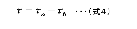
である。ただし、τbは回転中心Oに対するワイヤー11fによるトルクであり、τaと同様に算出できる。また、ワイヤー11eとワイヤー11fの両方によって発生する回転中心Oに対する剛性値Kは、

で表すことができる。ただし、Kθdはワイヤー10fの回転方向の弾性係数であり、Kθaと同様に算出できる。
また、左右方向に差をつける必要がない時は
[数6]
Kθd=Kθa・・・(式6)
とする。
また、左右方向に差をつける必要がない時は
[数6]
Kθd=Kθa・・・(式6)
とする。
これら式1から式6の方程式を用いて、直動方向の弾性係数KaとKdを算出し、それらを各モータのモータ制御信号として出力する。具体的にはKaはモータ14fのモータ制御信号K14fであり、Kdはモータ14eのモータ制御信号K14eである。
なお、式6は必ずしも上記の式に限るものではなく、例えば路面の状況や人の関節の特性などから例えばKθd=2Kθaなどとしてもよく、この場合も同様に求めることが可能である。
図14に右脚の歩行周期と腿ワイヤー10又は足首ワイヤー11の歩行周期と剛性目標値との関係の一例を示す。図14の横軸は右脚の歩行周期であり、縦軸は剛性目標値の大きさを示している。図14の3番目のグラフは、腿ワイヤー10e,10fの歩行周期と剛性目標値との関係の一例を示す。図14の6番目のグラフは、足首ワイヤー11e,11fの歩行周期と剛性目標値との関係の一例を示す。なお、図14の1番目及び2番目のグラフは、後述する変形例にかかる右脚太腿前後のワイヤー10a,10dの歩行周期と剛性目標値との関係の一例を示す。図14の4番目及び5番目のグラフは、後述する変形例にかかる右足首前後のワイヤー11a,11dの歩行周期と剛性目標値との関係の一例を示す。
図14の上から3番目のグラフに示すように、太腿の横方向では、アシストトルクを発生させず、剛性のみをアシストするため、1つの脚の左右の腿ワイヤー10である右脚の外側と内側との腿ワイヤー10eと10fにおいて、仮想的にバネ剛性を模擬する弾性係数をそれぞれ同時に大きくして、右脚の太腿での左右方向の剛性が大きくなるように、第1の剛性目標値出力部24で制御している。一例としては、1組の腿ワイヤー10eと10fの弾性係数を同じ値にして、右脚の外側と内側との腿ワイヤー10eと10fに同じ剛性が付与されるようにする。左脚でも同様である。
また、図14の上から6番目のグラフに示すように、足首の横方向でも、アシストトルクを発生させず、剛性のみをアシストするため、1つの脚の左右の足首ワイヤー11である右足首の外側と内側との足首ワイヤー11eと11fにおいて、剛性目標値をそれぞれ同時に大きくして、右脚の足首の左側面と右側面に伝達する剛性が大きくなるように、第1の剛性目標値出力部24で制御している。一例としては、1組の足首ワイヤー11eと11fの弾性係数を同じ値にして、右脚の外側と内側との足首ワイヤー11eと11fに同じ剛性が付与されるようにする。左脚でも同様である。
モータ制御部27は、モータ設定部26から入力された剛性目標値に基づき、1組のモータ13又は1組のモータ14の制御を行う。この結果、例えば、左右それぞれの足において、足の踵接地時から足が完全に接地面90から完全に離れた時までの区間の太腿又は足首の左側面と右側面に伝達する剛性が、他の区間の剛性よりも大きくなるように、第1の剛性目標値出力部24で1組のワイヤー10又は1組のワイヤー11の剛性を仮想的にバネとして模擬した張力を制御することができる(例えば、図14の3番目の1組のワイヤー10e,10f又は6番目の1組のワイヤー11e,11fのグラフを参照。)。すなわち、第1の剛性目標値出力部24は、ユーザ100の歩行周期情報に基づいて、第1の剛性目標値よりも第2の剛性目標値を小さくするとともに、脚が接地面90に接地する直前に第2の剛性目標値から第1の剛性目標値に変更して各太腿又は各足首の左右方向の剛性を大きくすることができる。ここで、第1の剛性目標値は、ユーザ100の足が接地面90に接触しているときの各太腿又は各足首の左側面と右側面に伝達する剛性の大きさであり、第2の剛性目標値は、ユーザ100の足が接地面90に接触していないときの各太腿又は各足首の左側面と右側面に伝達する剛性の大きさである。このように、足が接地面90に接地する直前から接地面90から離れるときまでの区間の各太腿又は各足首の剛性が大きくなるように剛性目標値を変更することにより、歩行中のユーザ100の各太腿又は各足首の左右方向への転倒を防止することができる。
ここで、モータ制御部27の動作を、より具体的に説明すると、次のとおりである。
モータ設定部26からモータ制御部27に入力された直動方向の剛性目標値(言い換えれば、直動の弾性係数)Kn(nは対応するモータ記号)と、左右それぞれの太腿又は足首の左側面と右側面に伝達する剛性を制御する1組のモータ13又は1組のモータ14それぞれから取得されたモータトルクτとを用いて、1組のモータ13又は1組のモータ14に対応する1組のワイヤー10又は1組のワイヤー11それぞれが仮想的なバネを模擬して動作するように力制御の計算をモータ制御部27で行い、モータ制御部27から、力制御の計算で求めたモータ13又は14の目標位置(言い換えれば、ワイヤー10又は11の下端の目標位置)xを1組のモータ13又は1組のモータ14それぞれに出力する。なお、一般にモータトルクτはモータ電流iを用いてτ=Kt×iとして求めることが可能である。Ktはモータ固有の定数である。
力制御の計算の一例は次の通りである。
モータトルクをτとし、そのときの1組のワイヤー10又は11それぞれの張力をFとすると、1組のワイヤー10又は1組のワイヤー11それぞれの張力Fは、以下の式で求めることが出来る。

ただし、Gはギア比及びプーリ半径rpから決まる変換係数である。
このときのモータ13又は14の目標位置xは、直動方向の剛性目標値Knを用いて以下のように決定される。
[数8]
x=(1/G)×(F/Kn)
以上の結果から、モータ13又は14の目標位置xが求められ、入出力インターフェース41を介して、モータ13又は14に出力される。
x=(1/G)×(F/Kn)
以上の結果から、モータ13又は14の目標位置xが求められ、入出力インターフェース41を介して、モータ13又は14に出力される。
1組のモータ13又は1組のモータ14それぞれは、入力されたモータ13又は14の目標位置xに移動する。それにより、1組のモータ13又は14それぞれに接続された1組のワイヤー10又は1組のワイヤー11それぞれは仮想的なバネを模擬して動作し、直動の剛性目標値Knのバネが発生させる張力と同等の張力を発生させることができる。
以上、1組のモータ13又は1組のモータ14それぞれが位置制御で動作している場合の例であるが、トルク制御で動作している場合も同様に実現することが可能である。
図15A及び図15Bは、モータ制御部27の動作を模式的に示した図である。ここで、各ワイヤー10又は11の張力は、歪ゲージ又はトルクセンサなどの力センサ42でそれぞれ検出することができる。力センサ42の一例としての歪ゲージを、例えば、ワイヤー10又は11の中間に配置させたり、ワイヤー10又は11の端部と下端腿ワイヤー取付部19又は下端足首ワイヤー取付部18との間に配置して(図15A及び図15B参照)、ワイヤー10又は11に発生する張力を検出することができる。また、ワイヤー10又は11の長さLの変動量ΔLについては、モータ13又は14のエンコーダ51でプーリ50の回転数を検出し、プーリ50の半径rpは既知であるので、半径rpと回転数との演算で、プーリ50に巻き取ったワイヤー10又は11の長さLの変動量ΔLを求めることができる。
図15Aに示すように、モータ制御部27では、事前に仮想的なバネの自然長L0が決められている。すなわち、ワイヤー10又は11の長さLがL0のとき、ワイヤー10又は11に発生する張力Fが0である。アシストウェア72としてアシストアンクルバンド2b,2c又はアシストパンツ2aをユーザ100が装着して、ワイヤの長さL0よりも長い位置で装着しようとした際、ワイヤー10又は11がプーリ50から引き出される。このとき、直動の剛性目標値Knのとき、モータ13又は14に発生している張力FがT1の場合、ワイヤー10又は11の長さがL0+ΔL1となるようにモータ13又は14の目標位置xを決定する。
ただし、
[数9]
ΔL1=T1/Kn
である。ギア比が1であり、プーリ50の半径がrpの場合、変換係数Gは2πrpとなるので、モータ13又は14の目標位置xは、
[数10]
x={1/(2πrp)}×ΔL1
となる。
ただし、
[数9]
ΔL1=T1/Kn
である。ギア比が1であり、プーリ50の半径がrpの場合、変換係数Gは2πrpとなるので、モータ13又は14の目標位置xは、
[数10]
x={1/(2πrp)}×ΔL1
となる。
次に、アシストウェア72を装着しているユーザ100が歩行又は走行などにより動いているとき、接地面90の状況に応じて転倒防止のため、左右の脚の太腿又は足首の左側面と右側面に伝達する剛性を大きくする場合を想定する。このとき、図15Bに示すように、ワイヤー10又は11に発生している張力FがT1からT2に変化する場合を考える。
このときのワイヤー10又は11の長さLはL0+ΔL1+ΔL2であり、ΔL2は次式で算出できる。
[数11]
ΔL2=T2/Kn
このとき、モータ13又は14の目標位置xは、
[数12]
x={1/(2πrp)}×(L0+ΔL2)
となる。
ΔL2=T2/Kn
このとき、モータ13又は14の目標位置xは、
[数12]
x={1/(2πrp)}×(L0+ΔL2)
となる。
モータ13又は14がトルク制御で動作している場合、モータ制御部27は、モータ設定部26から入力された直動の剛性目標値Knと、モータ13又は14から取得したモータ13又は14の位置情報である目標位置xとを用いて、ワイヤー10又は11が仮想的なバネを模擬して動作するように、力制御を行う。このため、モータ制御部27は、モータトルクτを計算し、モータ13又は14に出力する。
計算で求められたモータトルクτを実現するように、モータ制御部27によりモータ13又は14を正逆回転動作制御することで、モータ13又は14に接続されたワイヤー10又は11は仮想的なバネを模擬して引張又は緩められて、直動の剛性目標値Knのバネが発生させる張力と同等の張力をワイヤー10又は11に発生させることができる。
図16A~図16Cは、右太腿及び右腿の部分におけるアシストシステムの動作の様子を示した図である。図16Aにおいて、腿ワイヤー10fに発生している張力はT1rであり、腿ワイヤー10eに発生している張力はT1lであり、それぞれの張力によって股関節の回転中心101に対して発生しているトルクはτ0と-τ0であり、釣り合っている。このとき、太腿に対して左右に回転させるトルクは働いていない。
次に、ユーザ100が例えば段差部分に足を置いたことにより、太腿の回転中心101に対して-τ2のトルクが働いたとする(図16Bの状態。)。その結果、腿ワイヤー10fに働く張力はT2rになり、腿ワイヤー10eに働く張力はT2lになる。このときの張力の関係は、次のようになる。
[数13]
T1r<T2r ,T1l>T2l
腿ワイヤー10fに設定された直動の剛性目標値をK1とし、腿ワイヤー10eに設定された剛性目標値をK2とすると、腿ワイヤー10fと腿ワイヤー10eとは、ワイヤー10f,10eの目標長さの変化量ΔLr,ΔLlが次の式で計算できる。
T1r<T2r ,T1l>T2l
腿ワイヤー10fに設定された直動の剛性目標値をK1とし、腿ワイヤー10eに設定された剛性目標値をK2とすると、腿ワイヤー10fと腿ワイヤー10eとは、ワイヤー10f,10eの目標長さの変化量ΔLr,ΔLlが次の式で計算できる。
[数14]
ΔLr=(T2r-T1r)/K1 ,ΔLl=(T2l-T1l)/K2
ワイヤー10f,10eの目標長さに応じてモータ13f,13eがそれぞれ動作し、ワイヤー10f,10eの長さを変化させる。腿ワイヤー10fは引き出され、腿ワイヤー10eは巻き取られる。その結果、図16Cに示すように、股関節は内転する。また、腿ワイヤー10fの張力によって股関節の回転中心101に働くトルクはτ3rとなり、同じく、腿ワイヤー10eの張力によって働くトルクはτ3l(<0)となる。左右の腿ワイヤー10f及び10eによって発生するトルクが異なるため、釣り合いは崩れ股関節にはτ3=τ3r+τ3lのトルクが発生する。このトルクτ3が、段差に足をおいたことによって股関節に発生したトルク-τ2に対して逆向きとなるため、打ち消しあうことによって、アシストシステムがない時と比べて股関節の内転角度は小さくなる。また、外界から働くトルクがなくなった時には、釣り合いの状態、すなわち、図16Aの状態に戻ることができる。
以上のように、前記実施形態によれば、第1の例又は第3の例では、ユーザ100の右足首の右側面及び左側面にそれぞれ対応する部分にユーザ100の右脚の長手方向沿いに配置され、右の足首上ベルト6aの下端足首アウターワイヤー取付部16e,16fを通って、下端が、右の踵ベルト7aの下端足首ワイヤー取付部18e,18fに連結されている1組の足首ワイヤー11e,11fと、ユーザ100の左足首の右側面及び左側面にそれぞれ対応する部分にユーザ100の左脚の長手方向沿いに配置され、左の足首上ベルト6bの下端足首アウターワイヤー取付部16g,16hを通って、下端が、左の踵ベルト7bの下端足首ワイヤー取付部18g,18hに連結されている1組の足首ワイヤー11g,11hsを備えている。又、第2の例又は第3の例では、アシストパンツ本体2dにおいて、ユーザ100の右太腿外側(右太腿右側面)及び右太腿内側(右太腿左側面)にそれぞれ対応する部分に配置されて、下端が、腰部ベルト4と右脚の膝上ベルト5aの下端腿ワイヤー取付部19e,19fとに連結されている腿ワイヤー10e,10fと、アシストパンツ本体2dにおいて、ユーザ100の左太腿内側(左太腿右側面)及び左太腿外側(左太腿左側面)にそれぞれ対応する部分に配置されて、下端が、腰部ベルト4と左脚の膝上ベルト5bの下端腿ワイヤー取付部19g,19hとに連結されている腿ワイヤー10g,10hとを備えている。また、制御装置3は、モータ14又は13をそれぞれ独立して正逆回転動作制御することにより、ユーザ情報入力部12で取得したユーザの情報とフットセンサ8a,8bからの歩行情報とに基づいて、各ワイヤー11,10の長さをそれぞれ調整して、各ワイヤー11,10に付与する各足首又は各太腿での左側面と右側面に伝達する剛性を調整している。すなわち、例えば、左右それぞれの足において、歩行周期が0%の足の踵接地時から歩行周期が60%の足が完全に接地面90から完全に離れた時までの足首又は太腿の左側面と右側面に伝達する剛性を、他の区間の剛性よりも大きくなるように第1の剛性目標値出力部24で変更して、歩行中のユーザ100の左右方向への転倒を防止することができる。
また、制御装置3は、一例として、歩行周期推定部20と、アシスト強度決定部21と、タイミング決定部23と、第1の剛性目標値出力部24と、モータ設定部26と、モータ制御部27と、疲労度推定部29とを備えて構成している。第1の剛性目標値出力部24は、歩行周期推定部20からの歩行周期情報とアシスト強度決定部21からのアシスト強度情報とタイミング決定部23からの剛性変更タイミング情報とに基づき、太腿又は足首の左右方向に対する剛性の目標値を決定する。次いで、第1の剛性目標値出力部24は、モータ設定部26とモータ制御部27との働きにより、左右の腿ワイヤー10h,10f,10e,10g又は左右の足首ワイヤー11h,11f,11e,11gに接続されたモータ13又は14を制御する。このように構成することで、太腿又は足首の左側面と右側面に伝達する剛性を、仮想的なバネを模擬した張力として目標値通りに制御装置3で制御することが可能となる。これにより、アシストシステム1は、アシスト対象者であるユーザ100が歩行中に転倒することを可能な限り防止することができる。
また、アシスト強度決定部21において、ユーザ情報からアシストの強度を決定し、よりアシストが必要なユーザ100に対しては、アシスト力の一種である剛性を高く設定することが可能となる。タイミング決定部23は、歩行周期推定部20から出力されるユーザ100の歩行情報の一例である歩行周期情報に基づき、ユーザ100が足を接地する直前から接地面(例えば、路面又は床面など)90から離れるまでの間だけ剛性を上げることにより、転倒防止すると同時に、足が宙に浮いている時には足の関節の動きを阻害しないようにすることができる。これにより、例えば接地面90に障害物があるようなときにユーザ100が足を置く場所を調整しながら歩行するケースにおいて、ユーザ100の足の動きを阻害することなく、転倒防止することができる。
前記実施形態では、一例として太腿と足首関節との左右方向の剛性をアシストする歩行アシストパンツを例に説明を行ったが、これに限られるわけではない。
前記実施形態では、入力インターフェース部200の歩行情報を取得する歩行情報取得装置の一例としてフットセンサ8a,8bを例に説明を行ったが、これに限られるわけではなく、例えばアシストパンツ2a又はアシストアンクルバンド2b,2cに取り付けられた角度センサなどでもよい。
前記実施形態では、一例として左右両方の脚に対して剛性アシストを行う説明を行ったが、これに限られるわけではなく、どちらかの脚一方だけアシストでもかまわない。例えば、ケガをしていて片足にアシストシステム1を取り付けられない例など、片方の脚だけのアシストでも本実施形態は実施可能である。
以上のように、前記実施形態ではユーザ100の左右方向に対して、ユーザ100が足を接地する直前から接地面90から離れるまでの間だけ剛性を上げることにより、転倒防止すると同時に、脚が宙に浮いている時には脚の関節の動きを阻害しないようにすることができる。これにより、例えば接地面90に障害物があるようなときにユーザ100が足を置く場所を調整しながら歩行するケースにおいて、ユーザ100の脚の動きを阻害することなく、転倒防止することができる。
(変形例)
前記実施形態の1つの変形例として、ユーザ100の前後方向の歩行動作についてアシスト機能を付加する場合には、図17及び図18及び図19に示すように、腿ワイヤー10に右脚太腿前後のワイヤー10a,10dと左脚太腿前後のワイヤー10b,10cとをさらに追加することができる。さらに、モータ13として、ワイヤー10a,10d,10b,10cにそれぞれ対応したモータ13a,13d,13b,13cを追加して備えることができる。また、同様な目的で、足首ワイヤー11に右足首前後のワイヤー11a,11dと左足首前後のワイヤー11b,11cとをさらに追加することができる。さらに、モータ14として、ワイヤー11a,11d,11b,11cにそれぞれ対応したモータ14a,14d,14b,14cを追加して備えることができる。追加したそれぞれのワイヤーの一端には追加したそれぞれモータが接続されている。制御装置3は、ユーザ情報と歩行情報とに基づいて、追加したモータ13a,13d,13b,13cと追加したモータ14a,14d,14b,14cとをそれぞれ独立して制御することにより、前記太腿又は前記足首の前後方向のアシスト力を変更するように制御している。
前記実施形態の1つの変形例として、ユーザ100の前後方向の歩行動作についてアシスト機能を付加する場合には、図17及び図18及び図19に示すように、腿ワイヤー10に右脚太腿前後のワイヤー10a,10dと左脚太腿前後のワイヤー10b,10cとをさらに追加することができる。さらに、モータ13として、ワイヤー10a,10d,10b,10cにそれぞれ対応したモータ13a,13d,13b,13cを追加して備えることができる。また、同様な目的で、足首ワイヤー11に右足首前後のワイヤー11a,11dと左足首前後のワイヤー11b,11cとをさらに追加することができる。さらに、モータ14として、ワイヤー11a,11d,11b,11cにそれぞれ対応したモータ14a,14d,14b,14cを追加して備えることができる。追加したそれぞれのワイヤーの一端には追加したそれぞれモータが接続されている。制御装置3は、ユーザ情報と歩行情報とに基づいて、追加したモータ13a,13d,13b,13cと追加したモータ14a,14d,14b,14cとをそれぞれ独立して制御することにより、前記太腿又は前記足首の前後方向のアシスト力を変更するように制御している。
具体的には、図17及び図18及び図20に示すように、アシストパンツ2aには、追加の腿ワイヤー10として、アシストパンツ本体2dの右脚と左脚の前面に対応する部分に配置された前面側の腿ワイヤー10a、10bと、右脚と左脚の後面に対応する部分に配置された背中側の腿ワイヤー10d、10cとを備えている。また、アシストアンクルバンド2b,2cには、追加の足首ワイヤー11として、足首上ベルト6a,6bと踵ベルト7a,7bとの間の足首の前面に対応する部分に配置された前面側の足首ワイヤー11a、11bと、足首上ベルト6a,6bと踵ベルト7a,7bとの間の足首の後面に対応する部分に配置された背中側の足首ワイヤー11d、11cとを備えている。なお、足首アウターワイヤー15、下端足首アウターワイヤー取付部16、上端足首アウターワイヤー取付部17、下端足首ワイヤー取付部18、下端腿ワイヤー取付部19などのように図2と同様な構成については、同様な図番号を付すだけで、説明を省略する。
腿ワイヤー10aと10dが拮抗の関係にあり、腿ワイヤー10bと10cが拮抗の関係にある。よって、制御装置3の動作制御により、拮抗関係の1組の右脚の前側と後側との腿ワイヤー10aと10dとが、それぞれ引っ張り合うように駆動されることで、右脚の太腿に右脚太腿の前後のトルクを発生することができる。また、制御装置3の動作制御により、拮抗関係の1組の左脚の前側と後側との腿ワイヤー10bと10cとが、それぞれ引っ張り合うように駆動されることで、左脚の太腿に左脚太腿の前後のトルクを発生することができる。
足首ワイヤー11も同様に、足首ワイヤー11aと11dが拮抗の関係にあり、足首ワイヤー11bと11cが拮抗の関係にある。よって、制御装置3の動作制御により、拮抗関係の1組の右足首ワイヤー11aと11dとが、それぞれ引っ張り合うように駆動されることで、右足首の前後のトルクを発生することができる。また、制御装置3の動作制御により、拮抗関係の1組の左足首ワイヤー11bと11cとが、それぞれ引っ張り合うように駆動されることで、左足首の前後のトルクを発生することができる。
この変形例の場合には、制御装置3の一例としては、アシスト歩行のために、トルク目標値設定部25と第2の剛性目標値出力部28とをさらに備えることができる。
トルク目標値設定部25は、歩行周期推定部20から出力された歩行周期情報に基づき、歩行をアシストするトルク目標値を出力する。トルク目標値設定部25は、歩行周期情報に対しての目標トルク値を予め記憶しており、それに基づいて歩行をアシストするトルク値、すなわち、左右の脚を前後方向に動かす矢状方向のトルクの目標値を決定し、決定した矢状方向のトルクの目標値をモータ設定部26に出力する。左右の脚を前後方向に動かす矢状方向のトルクとは、腿ワイヤー10aと10dの1組によって発生する右太腿の前後のトルクと、腿ワイヤー10bと10cの1組によって発生する左太腿の前後のトルクと、足首ワイヤー11aと11dの1組によって発生する右足首関節の前後のトルクと、足首ワイヤー11bと11cの1組によって発生する左足首関節の前後のトルクとを指す。トルク目標値設定部25は、前額方向の運動に対しては、トルク目標値0を出力する。図19は、右足のワイヤーのグラフであり、前後の足の振りを作るためのトルクであって、横の剛性とはタイミングが異なる。
図19の上下のグラフは、それぞれ右足の股関節すなわち太腿と足首関節とのそれぞれの前後の動きに対するトルク目標値(言い換えれば、太腿の前後のアシストトルクと足首関節の前後のアシストトルク)の一例を示す図であって、前後の右足の振りを作るためのトルクを示している。太腿の前後のアシストトルクとは、ワイヤー10aとワイヤー10dの1組及びワイヤー10bとワイヤー10cの1組によってそれぞれ発生する太腿前後運動のアシストトルクのことを示す。また、足首関節の前後のアシストトルクとは、ワイヤー11aとワイヤー11dの1組及びワイヤー11bとワイヤー11cの1組によってそれぞれ発生する足首関節前後運動のアシストトルクのことを示す。図19の例では、ワイヤー10aとワイヤー10dの1組及びワイヤー10bとワイヤー10cの1組によって、歩行周期において左足が接地面90に接地したときから接地面90から離れるときまでの区間で、左足を屈曲させたのち伸展させて、アシスト力を発生させている。同様に、ワイヤー11aとワイヤー11dの1組及びワイヤー11bと11cの1組によって、歩行周期において左足が接地面90に接地したときから接地面90から離れるときまでの区間で、左足首を屈曲させて、アシスト力を発生させている。
第2の剛性目標値出力部28は、歩行周期推定部20から出力された歩行周期情報を基に矢状方向の運動の剛性目標値を決定し、決定した矢状方向の運動の剛性目標値を第2の剛性目標値出力部28からモータ設定部26に出力する。矢状方向の運動の剛性目標値は、歩行周期情報の関数として予め決定し、第2の剛性目標値出力部28が記憶している。
モータ設定部26は、先の実施形態と同様に第1の剛性目標値出力部24から出力された剛性の目標値と共に、第2の剛性目標値出力部28から出力された剛性の目標値と、トルク目標値設定部25から出力されたトルク目標値とに基づき、腿と足首とのワイヤー10,11に対応したモータ13、14の設定値を設定し、設定した腿と足首とのワイヤー10,11に対応したモータ13、14の設定値をモータ設定部26からモータ制御部27に出力する。
図14のうちの1番目と2番目のグラフと4番目と5番目のグラフに、それぞれ、右足の腿ワイヤー10a,10d,11a,11dの歩行周期と模擬する剛性の目標弾性係数との関係の一例を示す。
図14の1番目と2番目のグラフに示すように、ワイヤー10aと10dは、太腿前後のトルク及び剛性をバネ剛性と模擬してアシストするワイヤーであり、前後には、剛性をバネ剛性と模擬してアシストせず、トルクのみをアシストした例である。この場合、歩行周期の情報に基づいて脚を後ろに振る伸展方向へのアシストトルクが必要な時は、太腿後側のワイヤーであるワイヤー10dの張力が大きくなるとともに、歩行周期の情報に基づいて逆向きの時は、太腿前側のワイヤーであるワイヤー10aの張力が大きくなるように、第1の剛性目標値出力部24で制御している。
図14の4番目と5番目のグラフに示すように、足首も同様に、足首を屈曲させるアシストトルクを発生させる時に、歩行周期の情報に基づいて足首を後ろに曲げて伸展方向へのアシストトルクが必要な時は、足首の後側のワイヤーであるワイヤー11dの張力が大きくなり、歩行周期の情報に基づいて逆向きの時は、足首の前側のワイヤーであるワイヤー11aの張力が大きくなるように、第1の剛性目標値出力部24で制御している。
この変形例によれば、ユーザ100の前後方向の歩行アシストと、ユーザの対象部位の左側面と右側面での剛性アシストとを同時に達成することができる。
また、図21は、歩行転倒防止装置の足首下ベルトの別の例を示す説明図である。足首下ベルトとしては、踵に引っ掛ける踵ベルト7aに限られるものではなく、甲から、踵よりも足先側の付近に引っ掛ける足首下ベルト7xとしてもよい。
また、張力を付与する張力付与機構70の例として、前記実施形態ではモータ14などの構成で説明したが、これに限られるものではなく、リニアアクチュエータで同様な作用効果を奏することもできる。
なお、本開示を実施形態及び変形例に基づいて説明してきたが、本開示は、前記の実施形態及び変形例に限定されないのはもちろんである。以下のような場合も本開示に含まれる。
前記制御装置3の一部又は全部は、具体的には、マイクロプロセッサ、ROM、RAM、ハードディスクユニットなどから構成されるコンピュータシステムである。前記RAM又はハードディスクユニットには、コンピュータプログラムが記憶されている。前記マイクロプロセッサが、前記コンピュータプログラムにしたがって動作することにより、各部は、その機能を達成する。ここでコンピュータプログラムは、所定の機能を達成するために、コンピュータに対する指令を示す命令コードが複数個組み合わされて構成されたものである。
例えば、ハードディスク又は半導体メモリ等の記録媒体に記録されたソフトウェア・プログラムをCPU等のプログラム実行部が読み出して実行することによって、各構成要素が実現され得る。
なお、前記実施形態又は変形例における制御装置を構成する要素の一部又は全部を実現するソフトウェアは以下のようなプログラムである。
つまり、このプログラムは、複数のベルトと複数のワイヤーを含む装置のための制御方法をコンピュータに実行させるプログラムであって、前記複数のベルトは、ユーザの左の足首上部に固定される左の足首上ベルトと、前記ユーザの右の足首上部に固定される右の足首上ベルトと、前記ユーザの左の足首下部に固定される左の足首下ベルトと、前記ユーザの右の足首下部に固定される右の足首下ベルトを含み、前記複数のワイヤーは、前記右の足首上ベルトと前記右の足首下ベルトとに連結される第1のワイヤーと、前記右の足首上ベルトと前記右の足首下ベルトとに連結される第2のワイヤーと、前記左の足首上ベルトと前記左の足首下ベルトとに連結される第3のワイヤーと、前記左の足首上ベルトと前記左の足首下ベルトとに連結される第4のワイヤーを含み、前記第1のワイヤーの少なくとも一部は前記右足首の右側面に沿って配置され、前記第2のワイヤーの少なくとも一部は前記右足首の左側面に沿って配置され、前記第3のワイヤーの少なくとも一部は前記左足首の右側面に沿って配置され、前記第4のワイヤーの少なくとも一部は前記左足首の左側面に沿って配置され、前記制御方法は、前記ユーザのユーザ情報と前記ユーザの歩行動作を示す歩行情報とを取得し、前記ユーザ情報と前記歩行情報に基づいて、前記第1のワイヤーの第1剛性目標値、前記第2のワイヤーの第2剛性目標値、前記第3のワイヤーの第3剛性目標値、前記第4のワイヤーの第4剛性目標値を決定し、前記第1剛性目標値を用いて、前記第1のワイヤーの張力を制御し、前記第2剛性目標値を用いて、前記第2のワイヤーの張力を制御し、前記第3剛性目標値を用いて、前記第3のワイヤーの張力を制御し、前記第4剛性目標値を用いて、前記第4のワイヤーの張力を制御し、前記第1のワイヤーの張力制御と前記第2のワイヤーの張力制御は同時に行われ、前記第3のワイヤーの張力制御と前記第4のワイヤーの張力制御は同時に行われるプログラムである。
また、別のプログラムは、複数のベルトと複数のワイヤーを含む装置のための制御方法をコンピュータに実行させるプログラムであって、前記複数のベルトは、前記ユーザの腰部に固定される腰部ベルトと、前記左の脚の膝上部に固定される左膝上ベルトと、前記右の脚の膝上部に固定される右膝上ベルトを含み、前記複数のワイヤーは、前記腰部ベルトと前記右膝上ベルトとに連結される第5のワイヤーと、前記腰部ベルトと前記右膝上ベルトとに連結される第6のワイヤーと、前記腰部ベルトと前記左膝上ベルトとに連結される第7のワイヤーと、前記腰部ベルトと前記左膝上ベルトとに連結される第8のワイヤーを含み、前記第5のワイヤーの少なくとも一部は前記ユーザの右太腿の右側面に配置され、前記第6のワイヤーの少なくとも一部は前記右太腿の左側面に配置され、前記第7のワイヤーの少なくとも一部は前記ユーザの左太腿の右側面に配置され、前記第8のワイヤーの少なくとも一部は前記左太腿の左側面に配置され、前記制御方法は、前記ユーザのユーザ情報と前記ユーザの歩行動作を示す歩行情報とを取得し、前記ユーザ情報と前記歩行情報に基づいて、前記第5のワイヤーの第5剛性目標値、前記第6のワイヤーの第6剛性目標値、前記第7のワイヤーの第7剛性目標値、前記第8のワイヤーの第8剛性目標値を決定し、前記第5剛性目標値を用いて、前記第5のワイヤーの張力を制御し、前記第6剛性目標値を用いて、前記第6のワイヤーの張力を制御し、前記第7剛性目標値を用いて、前記第7のワイヤーの張力を制御し、前記第8剛性目標値を用いて、前記第8のワイヤーの張力を制御し、前記第5のワイヤーの張力制御と前記第6のワイヤーの張力制御は同時に行われ、前記第7のワイヤーの張力制御と前記第8のワイヤーの張力制御は同時に行われるプログラムである。
また、このプログラムは、サーバなどからダウンロードされることによって実行されてもよく、所定の記録媒体(例えば、CD-ROMなどの光ディスク、磁気ディスク、又は、半導体メモリなど)に記録されたプログラムが読み出されることによって実行されてもよい。
また、このプログラムを実行するコンピュータは、単数であってもよく、複数であってもよい。すなわち、集中処理を行ってもよく、あるいは分散処理を行ってもよい。
なお、上記様々な実施形態又は変形例のうちの任意の実施形態又は変形例を適宜組み合わせることにより、それぞれの有する効果を奏するようにすることができる。また、実施形態同士の組み合わせ又は変形例同士の組み合わせ又は実施形態と変形例との組み合わせが可能であると共に、異なる実施形態又は変形例の中の特徴同士の組み合わせも可能である。
本開示の前記態様にかかる歩行転倒防止、制御装置、制御方法、並びに、プログラムは、ユーザの左右の横方向に転倒を可能な限り防止でき、ユーザに装着して歩行時における転倒を防止する歩行転倒防止装置、歩行転倒防止装置の制御装置及び制御方法、並びに、歩行転倒防止装置用の制御プログラムに有用である。
1 アシストシステム
2 アシスト機構
2a アシストパンツ
2b,2c アシストアンクルバンド
2d アシストパンツ本体
3 制御装置
4 腰部ベルト
5a,5b 膝上ベルト
6a,6b 足首上ベルト
7a,7b,7x 足首下ベルト
8a,8b フットセンサ
10,10a,10b,10c,10d,10e,10f,10g,10h,10i 腿ワイヤー
11,11a,11b,11c,11d,11e,11f,11g,11h,11i 足首ワイヤー
12 ユーザ情報入力部
12a タッチパネル
13 腿ワイヤーモータ
13e,13f,13g,13h 腿モータ
14 足首ワイヤーモータ
14e,14f,14g,14h 足首モータ
15,15a,15b,15c,15d,15e,15f,15g,15h,15i 足首アウターワイヤー
16,16a,16b,16c,16d,16e,16f,16g,16h,16i 下端足首アウターワイヤー取付部
17,17e,17f,17g,17h 上端足首アウターワイヤー取付部
18,18e,18f,18g,18h 下端足首ワイヤー取付部
19,19e,19f,19g,19h 下端腿ワイヤー取付部
20 歩行周期推定部
21 アシスト強度決定部
23 タイミング決定部
24 第1の剛性目標値出力部
25 トルク目標値設定部
26 モータ設定部
27 モータ制御部
28 第2の剛性目標値出力部
29 疲労度推定部
40 制御プログラム(制御器)
41 入出力IF
42 力センサ
50 プーリ
51 エンコーダ
70 張力付与機構
72 アシストウェア
90 接地面
100 ユーザ
101 右腿部回転中心
151 前額面
152 矢状面
200 入力インターフェース部
Claims (20)
- ユーザの左の足首上部に固定される左の足首上ベルトと、
前記ユーザの右の足首上部に固定される右の足首上ベルトと、
前記ユーザの左の足首下部に固定される左の足首下ベルトと、
前記ユーザの右の足首下部に固定される右の足首下ベルトと、
前記右の足首上ベルトと前記右の足首下ベルトとに連結される第1のワイヤーと、
前記右の足首上ベルトと前記右の足首下ベルト(7a)とに連結される第2のワイヤーと、
前記第1のワイヤーの少なくとも一部は前記右足首の右側面に沿って配置され、
前記第2のワイヤーの少なくとも一部は前記右足首の左側面に沿って配置され、
前記左の足首上ベルトと前記左の足首下ベルトとに連結される第3のワイヤーと、
前記左の足首上ベルトと前記左の足首下ベルトとに連結される第4のワイヤーと、
前記第3のワイヤーの少なくとも一部は前記左足首の右側面に沿って配置され、
前記第4のワイヤーの少なくとも一部は前記左足首の左側面に沿って配置され、
前記第1のワイヤーの張力を制御する第1張力制御器と、
前記第2のワイヤーの張力を制御する第2張力制御器と、
前記第3のワイヤーの張力を制御する第3張力制御器と、
前記第4のワイヤーの張力を制御する第4張力制御器と、
前記ユーザのユーザ情報と前記ユーザの歩行動作を示す歩行情報とを取得する取得器と、
制御器を含み、
前記制御器は、前記ユーザ情報と前記歩行情報路に基づいて、前記第1のワイヤーの第1剛性目標値、前記第2のワイヤーの第2剛性目標値、前記第3のワイヤーの第3剛性目標値、前記第4のワイヤーの第4剛性目標値を決定し、
前記制御器は、前記第1剛性目標値を用いて、前記第1張力制御器に、前記第1のワイヤーの張力を制御させ、
前記制御器は、前記第2剛性目標値を用いて、前記第2張力制御器に、前記第2のワイヤーの張力を制御させ、
前記制御器は、前記第3剛性目標値を用いて、前記第3張力制御器に、前記第3のワイヤーの張力を制御させ、
前記制御器は、前記第4剛性目標値を用いて、前記第4張力制御器に、前記第4のワイヤーの張力を制御させ、
前記第1のワイヤーの張力制御と前記第2のワイヤーの張力制御は同時に行われ、
前記第3のワイヤーの張力制御と前記第4のワイヤーの張力制御は同時に行われる
歩行転倒防止装置。 - 前記第1張力制御器は、前記第1のワイヤーが連結される第1回転軸を有して、前記第1回転軸の回転制御により、前記第1のワイヤーの張力を制御する第1のモータを含み、
前記第2張力制御器は、前記第2のワイヤーが連結される第2回転軸を有して、前記第2回転軸の回転制御により、前記第2のワイヤーの張力を制御する第2のモータを含み、
前記第3張力制御器は、前記第3のワイヤーが連結される第3回転軸を有して、前記第3回転軸の回転制御により、前記第3のワイヤーの張力を制御する第3のモータを含み、
前記第4張力制御器は、前記第4のワイヤーが連結される第4回転軸を有して、前記第4回転軸の回転制御により、前記第4のワイヤーの張力を制御する第4のモータを含み、
前記制御器は、前記第1のモータに前記第1回転軸の回転制御のための指示を行い、前記第2のモータに前記第2回転軸の回転制御のための指示を行い、前記第3のモータに前記第3回転軸の回転制御のための指示を行い、前記第4のモータに前記第4回転軸の回転制御のための指示を行う
請求項1に記載の歩行転倒防止装置。 - 前記歩行転倒防止装置は、
前記ユーザの腰部に固定される腰部ベルトと、
前記左の脚の膝上部に固定される左膝上ベルトと、
前記右の脚の膝上部に固定される右膝上ベルトと、
前記腰部ベルトと前記右膝上ベルトとに連結される第5のワイヤーと、
前記腰部ベルトと前記右膝上ベルトとに連結される第6のワイヤーと、
前記腰部ベルトと前記左膝上ベルトとに連結される第7のワイヤーと、
前記腰部ベルトと前記左膝上ベルトとに連結される第8のワイヤーと、
前記第5のワイヤーの少なくとも一部は前記ユーザの右太腿の右側面に配置され、
前記第6のワイヤーの少なくとも一部は前記右太腿の左側面に配置され、
前記第7のワイヤーの少なくとも一部は前記ユーザの左太腿の右側面に配置され、
前記第8のワイヤーの少なくとも一部は前記左太腿の左側面に配置され、
前記第5のワイヤーの張力を制御する第5の張力制御器と、
前記第6のワイヤーの張力を制御する第6の張力制御器と、
前記第7のワイヤーの張力を制御する第7の張力制御器と、
前記第8のワイヤーの張力を制御する第8の張力制御器とをさらに備え、
前記制御器は前記ユーザ情報と前記歩行情報に基づいて、前記第5のワイヤーの第5剛性目標値、前記第6のワイヤーの第6剛性目標値、前記第7のワイヤーの第7剛性目標値、前記第8のワイヤーの第8剛性目標値を決定し、
前記制御器は、前記第5剛性目標値を用いて、前記第5張力制御器に、前記第5のワイヤーの張力を制御させ、
前記制御器は、前記第6剛性目標値を用いて、前記第6張力制御器に、前記第6のワイヤーの張力を制御させ、
前記制御器は、前記第7剛性目標値を用いて、前記第7張力制御器に、前記第7のワイヤーの張力を制御させ、
前記制御器は、前記第8剛性目標値を用いて、前記第8張力制御器に、前記第8のワイヤーの張力を制御させ、
前記第5のワイヤーの張力制御と前記第6のワイヤーの張力制御は同時に行われ、
前記第7のワイヤーの張力制御と前記第8のワイヤーの張力制御は同時に行われる
請求項1に記載の歩行転倒防止装置。 - 前記第5張力制御器は、前記第5のワイヤーが連結される第5回転軸を有して、前記第5回転軸の回転制御により、前記第5のワイヤーの張力を制御する第5のモータを含み、
前記第6張力制御器は、前記第6のワイヤーが連結される第6回転軸を有して、前記第6回転軸の回転制御により、前記第6のワイヤーの張力を制御する第6のモータを含み、
前記第7張力制御器は、前記第7のワイヤーが連結される第7回転軸を有して、前記第7回転軸の回転制御により、前記第7のワイヤーの張力を制御する第7のモータを含み、
前記第8張力制御器は、前記第8のワイヤーが連結される第8回転軸を有して、前記第8回転軸の回転制御により、前記第8のワイヤーの張力を制御する第8のモータを含み、
前記制御部は、前記第5張力制御器に前記第5回転軸の回転制御のための指示を行い、前記第6張力制御器に前記第6回転軸の回転制御のための指示を行い、前記第7張力制御器に前記第7回転軸の回転制御のための指示を行い、前記第8張力制御器に前記第8回転軸の回転制御のための指示を行う
請求項3に記載の歩行転倒防止装置。 - ユーザの腰部に固定される腰部ベルトと、
前記ユーザの左の脚の膝上部に固定される左膝上ベルトと、
前記ユーザの右の脚の膝上部に固定される右膝上ベルトと、
前記腰部ベルトと前記右膝上ベルトとに連結される第5のワイヤーと、
前記腰部ベルトと前記右膝上ベルトとに連結される第6のワイヤーと、
前記腰部ベルトと前記左膝上ベルトとに連結される第7のワイヤーと、
前記腰部ベルトと前記左膝上ベルトとに連結される第8のワイヤーと、
前記第5のワイヤーの少なくも一部は前記ユーザの右太腿の右側面に沿って配置され、
前記第6のワイヤーの少なくも一部は前記右太腿の左側面に沿って配置され、
前記第7のワイヤーの少なくも一部は前記ユーザの左太腿の右側面に沿って配置され、
前記第8のワイヤーの少なくも一部は前記左太腿の左側面に沿って配置され、
前記第5のワイヤーの張力を制御する第5の張力制御器と、
前記第6のワイヤーの張力を制御する第6の張力制御器と、
前記第7のワイヤーの張力を制御する第7の張力制御器と、
前記第8のワイヤーの張力を制御する第8の張力制御器と、
前記ユーザのユーザ情報と前記ユーザの歩行動作を示す歩行情報とを取得する取得器と、
制御器を含み、
前記制御器は、前記ユーザ情報と前記歩行情報に基づいて、前記第5のワイヤーの第5剛性目標値、前記第6のワイヤーの第6剛性目標値、前記第7のワイヤーの第7剛性目標値、前記第8のワイヤーの第8剛性目標値を決定し、
前記制御器は、前記第5剛性目標値を用いて、前記第5張力制御器に、前記第5のワイヤーの張力を制御させ、
前記制御器は、前記第6剛性目標値を用いて、前記第6張力制御器に、前記第6のワイヤーの張力を制御させ、
前記制御器は、前記第7剛性目標値を用いて、前記第7張力制御器に、前記第7のワイヤーの張力を制御させ、
前記制御器は、前記第8剛性目標値を用いて、前記第8張力制御器に、前記第8のワイヤーの張力を制御させ、
前記第5のワイヤーの張力制御と前記第6のワイヤーの張力制御は同時に行われ、
前記第7のワイヤーの張力制御と前記第8のワイヤーの張力制御は同時に行われる
歩行転倒防止装置。 - 前記第5張力制御器は、前記第5のワイヤーが連結される第5回転軸を有して、前記第5回転軸の回転制御により、前記第5のワイヤーの張力を制御する第5のモータを含み、
前記第6張力制御器は、前記第6のワイヤーが連結される第6回転軸を有して、前記第6回転軸の回転制御により、前記第6のワイヤーの張力を制御する第6のモータを含み、
前記第7張力制御器は、前記第7のワイヤーが連結される第7回転軸を有して、前記第7回転軸の回転制御により、前記第7のワイヤーの張力を制御する第7のモータを含み、
前記第8張力制御器は、前記第8のワイヤーが連結される第8回転軸を有して、前記第8回転軸の回転制御により、前記第8のワイヤーの張力を制御する第8のモータを含み、
前記制御部は、前記第5張力制御器に前記第5回転軸の回転制御のための指示を行い、前記第6張力制御器に前記第6回転軸の回転制御のための指示を行い、前記第7張力制御器に前記第7回転軸の回転制御のための指示を行い、前記第8張力制御器に前記第8回転軸の回転制御のための指示を行う
請求項5に記載の歩行転倒防止装置。 - 前記第1剛性目標値は前記第2剛性目標値と等しく、かつ、前記第3剛性目標値は前記第4剛性目標値と等しい、
前記第5剛性目標値は前記第6剛性目標値と等しく、かつ、前記第7剛性目標値は前記第8剛性目標値と等しい、
請求項3~4のいずれか1つに記載の歩行転倒防止装置。 - 前記制御部は、
(i)前記第1ワイヤーに発生している力に基づき、前記第1回転軸の回転制御のための指示を行い、前記第2ワイヤーに発生している力に基づき、前記第2回転軸の回転制御のための指示を行い、前記第3ワイヤーに発生している力に基づき、前記第3回転軸の回転制御のための指示を行い、前記第4ワイヤーに発生している力に基づき、前記第4回転軸の回転制御のための指示を行い、前記第5ワイヤーに発生している力に基づき、前記第5回転軸の回転制御のための指示を行い、前記第6ワイヤーに発生している力に基づき、前記第6回転軸の回転制御のための指示を行い、前記第7ワイヤーに発生している力に基づき、前記第7回転軸の回転制御のための指示を行い、前記第8ワイヤーに発生している力に基づき、前記第8回転軸の回転制御のための指示を行い、または、
(ii)前記第1ワイヤーの長さに基づき、前記第1回転軸の回転制御のための指示を行い、前記第2ワイヤーの長さに基づき、前記第2回転軸の回転制御のための指示を行い、前記第3ワイヤーの長さに基づき、前記第3回転軸の回転制御のための指示を行い、前記第4ワイヤーの長さに基づき、前記第4回転軸の回転制御のための指示を行い、前記第5ワイヤーの長さに基づき、前記第5回転軸の回転制御のための指示を行い、前記第6ワイヤーの長さに基づき、前記第6回転軸の回転制御のための指示を行い、前記第7ワイヤーの長さに基づき、前記第7回転軸の回転制御のための指示を行い、前記第8ワイヤーの長さに基づき、前記第8回転軸の回転制御のための指示を行う
請求項3または4に記載の歩行転倒防止装置。 - 前記取得器は、
前記ユーザの年齢に関する情報、前記ユーザの脚のケガ又は障害の有無に関する情報、及び前記ユーザの疲労度合を示す情報のうちの少なくとも一つを前記ユーザ情報として取得し、
前記制御器は、
前記年齢が高いほど、前記第1剛性目標値、前記第第2剛性目標値、前記第3剛性目標値、前記第4剛性目標値、前記第5剛性目標値、前記第第6剛性目標値、前記第7剛性目標値、前記第8剛性目標値が大きくなるように変更し、
前記脚のケガ又は障害が有れば、前記第1剛性目標値、前記第第2剛性目標値、前記第3剛性目標値、前記第4剛性目標値、前記第5剛性目標値、前記第第6剛性目標値、前記第7剛性目標値、前記第8剛性目標値が大きくなるように変更し、
前記疲労度合が大きいほど、前記第1剛性目標値、前記第第2剛性目標値、前記第3剛性目標値、前記第4剛性目標値、前記第5剛性目標値、前記第第6剛性目標値、前記第7剛性目標値、前記第8剛性目標値が大きくなるように変更する、
請求項3~4のいずれか1つに記載の歩行転倒防止装置。 - 前記歩行情報は、第1疲労度ポイントと第2疲労度ポイントに基づく前記ユーザの経時的疲労度を含み、
前記第2疲労度ポイントは、前記ユーザの歩行開始から現在までの時間である歩行時間に基づいて決定され、
前記第1疲労度ポイントは、歩行時間が経過するに従い、前記所定時間の歩行の歩数が少なくなると増加し、
前記第2疲労度ポイントは、歩行時間が増加すると増加し、
前記第1疲労度ポイントが増加すると前記経時的疲労度は増加し、
前記第2疲労度ポイントが増加すると前記経時的疲労度は増加し、
前記制御器は、前記経時的疲労度が閾値より大きいと判定された場合、前記第1剛性目標値、前記第第2剛性目標値、前記第3剛性目標値、前記第4剛性目標値、前記第5剛性目標値、前記第第6剛性目標値、前記第7剛性目標値、前記第8剛性目標値を大きくする
請求項3または4に記載の歩行転倒防止装置。 - 前記取得器は、前記歩行情報を取得する歩行情報取得装置を備え、
前記制御器は、前記歩行情報取得装置で取得した前記歩行情報に基づいて、前記第1剛性目標値、前記第第2剛性目標値、前記第3剛性目標値、前記第4剛性目標値、前記第5剛性目標値、前記第第6剛性目標値、前記第7剛性目標値、前記第8剛性目標値を変更するタイミングを制御する、
請求項3または4に記載の歩行転倒防止装置。 - 前記歩行情報は、前記ユーザの歩行周期情報であり、
前記歩行周期情報は前記ユーザの右足の歩行1周期における前記右足と歩行面の接触する時間情報を含み、
前記第11剛性目標値は、前記右足が接地面に接触しているときの前記第1剛性目標値であり、
前記第12剛性目標値は、前記右足が接地面に接触しているときの前記第2剛性目標値であり、
前記第15剛性目標値は、前記右足が接地面に接触しているときの前記第5剛性目標値であり、
前記第16剛性目標値は、前記右足が接地面に接触しているときの前記第6剛性目標値であり、
前記第21剛性目標値は、前記右足が接地面に接触していないときの前記第1剛性目標値であり、
前記第22剛性目標値は、前記右足が接地面に接触していないときの前記第2剛性目標値であり、
前記第25剛性目標値は、前記右足が接地面に接触していないときの前記第5剛性目標値であり、
前記第26剛性目標値は、前記右足が接地面に接触していないときの前記第6剛性目標値であり、
前記制御部は、前記歩行周期情報に基づいて、現在の歩行周期において前記右足が前記歩行面に接地する直前に、
第1剛性目標値を前記第21剛性目標値から前記第11剛性目標値に変更し、
第2剛性目標値を前記第22剛性目標値から前記第12剛性目標値に変更し、
第5剛性目標値を前記第25剛性目標値から前記第15剛性目標値に変更し、
第6剛性目標値を前記第26剛性目標値から前記第16剛性目標値に変更する
請求項11に記載の歩行転倒防止装置。 - 前記ユーザの前記歩行情報は、前記ユーザの歩行周期情報であり、
前記剛性制御部は、前記ユーザの前記歩行周期情報に基づいて、予想される接地時の所定時間前に、遊脚期間におけるある所定期間より前の剛性値よりも剛性値を大きくするように制御する、
請求項11に記載の歩行転倒防止装置。 - 前記制御部は、前記歩行周期情報に基づいて、現在の歩行周期における前記右足が前記歩行面に接地していない状態において、
第1剛性目標値を前記第11剛性目標値から前記第21剛性目標値に変更し、
第2剛性目標値を前記第12剛性目標値から前記第22剛性目標値に変更し、
第5剛性目標値を前記第15剛性目標値から前記第25剛性目標値に変更し、
第6剛性目標値を前記第16剛性目標値から前記第26剛性目標値に変更する
請求項12に記載の歩行転倒防止装置。 - 複数のベルトと複数のワイヤーを含む装置のための制御装置であって、
前記複数のベルトは、ユーザの左の足首上部に固定される左の足首上ベルトと、前記ユーザの右の足首上部に固定される右の足首上ベルトと、前記ユーザの左の足首下部に固定される左の足首下ベルトと、前記ユーザの右の足首下部に固定される右の足首下ベルトを含み、
前記複数のワイヤーは、前記右の足首上ベルトと前記右の足首下ベルトとに連結される第1のワイヤーと、前記右の足首上ベルトと前記右の足首下ベルトとに連結される第2のワイヤーと、前記左の足首上ベルトと前記左の足首下ベルトとに連結される第3のワイヤーと、前記左の足首上ベルトと前記左の足首下ベルトとに連結される第4のワイヤーを含み、
前記第1のワイヤーの少なくとも一部は前記右足首の右側面に沿って配置され、
前記第2のワイヤーの少なくとも一部は前記右足首の左側面に沿って配置され、
前記第3のワイヤーの少なくとも一部は前記左足首の右側面に沿って配置され、
前記第4のワイヤーの少なくとも一部は前記左足首の左側面に沿って配置され、
前記制御装置は、
前記第1のワイヤーの張力を制御する第1張力制御器と、
前記第2のワイヤーの張力を制御する第2張力制御器と、
前記第3のワイヤーの張力を制御する第3張力制御器と、
前記第4のワイヤーの張力を制御する第4張力制御器と、
前記ユーザのユーザ情報と前記ユーザの歩行動作を示す歩行情報とを取得する取得器と、
制御器を含み、
前記制御器は、前記ユーザ情報と前記歩行情報に基づいて、前記第1のワイヤーの第1剛性目標値、前記第2のワイヤーの第2剛性目標値、前記第3のワイヤーの第3剛性目標値、前記第4のワイヤーの第4剛性目標値を決定し、
前記制御器は、前記第1剛性目標値を用いて、前記第1張力制御器に、前記第1のワイヤーの張力を制御させ、
前記制御器は、前記第2剛性目標値を用いて、前記第2張力制御器に、前記第2のワイヤーの張力を制御させ、
前記制御器は、前記第3剛性目標値を用いて、前記第3張力制御器に、前記第3のワイヤーの張力を制御させ、
前記制御器は、前記第4剛性目標値を用いて、前記第4張力制御器に、前記第4のワイヤーの張力を制御させ、
前記第1のワイヤーの張力制御と前記第2のワイヤーの張力制御は同時に行われ、
前記第3のワイヤーの張力制御と前記第4のワイヤーの張力制御は同時に行われる
制御装置。 - 複数のベルトと複数のワイヤーを含む装置のための制御装置であって、
前記複数のベルトは、ユーザの腰部に固定される腰部ベルトと、前記ユーザの左の脚の膝上部に固定される左膝上ベルトと、前記ユーザの右の脚の膝上部に固定される右膝上ベルトを含み、
前記複数のワイヤーは、前記腰部ベルトと前記右膝上ベルトとに連結される第5のワイヤーと、前記腰部ベルトと前記右膝上ベルトとに連結される第6のワイヤーと、前記腰部ベルトと前記左膝上ベルトとに連結される第7のワイヤーと、前記腰部ベルトと前記左膝上ベルトとに連結される第8のワイヤーを含み、
前記第5のワイヤーの少なくとも一部は前記ユーザの右太腿の右側面に配置され、
前記第6のワイヤーの少なくとも一部は前記右太腿の左側面に配置され、
前記第7のワイヤーの少なくとも一部は前記ユーザの左太腿の右側面に配置され、
前記第8のワイヤーの少なくとも一部は前記左太腿の左側面に配置され、
前記制御装置は、
前記第5のワイヤーの張力を制御する第5の張力制御器と、
前記第6のワイヤーの張力を制御する第6の張力制御器と、
前記第7のワイヤーの張力を制御する第7の張力制御器と、
前記第8のワイヤーの張力を制御する第8の張力制御器と、
前記ユーザのユーザ情報と前記ユーザの歩行動作を示す歩行情報とを取得する取得器と、
制御器を含み、
前記制御器は、前記ユーザ情報と前記歩行情報に基づいて、前記第5のワイヤーの第5剛性目標値、前記第6のワイヤーの第6剛性目標値、前記第7のワイヤーの第7剛性目標値、前記第8のワイヤーの第8剛性目標値を決定し、
前記制御器は、前記第5剛性目標値を用いて、前記第5張力制御器に、前記第5のワイヤーの張力を制御させ、
前記制御器は、前記第6剛性目標値を用いて、前記第6張力制御器に、前記第6のワイヤーの張力を制御させ、
前記制御器は、前記第7剛性目標値を用いて、前記第7張力制御器に、前記第7のワイヤーの張力を制御させ、
前記制御器は、前記第8剛性目標値を用いて、前記第8張力制御器に、前記第8のワイヤーの張力を制御させ、
前記第5のワイヤーの張力制御と前記第6のワイヤーの張力制御は同時に行われ、
前記第7のワイヤーの張力制御と前記第8のワイヤーの張力制御は同時に行われる
制御装置。 - 複数のベルトと複数のワイヤーを含む装置のための制御方法であって、
前記複数のベルトは、ユーザの左の足首上部に固定される左の足首上ベルトと、前記ユーザの右の足首上部に固定される右の足首上ベルトと、前記ユーザの左の足首下部に固定される左の足首下ベルトと、前記ユーザの右の足首下部に固定される右の足首下ベルトを含み、
前記複数のワイヤーは、前記右の足首上ベルトと前記右の足首下ベルトとに連結される第1のワイヤーと、前記右の足首上ベルトと前記右の足首下ベルトとに連結される第2のワイヤーと、前記左の足首上ベルトと前記左の足首下ベルトとに連結される第3のワイヤーと、前記左の足首上ベルトと前記左の足首下ベルトとに連結される第4のワイヤーを含み、
前記第1のワイヤーの少なくとも一部は前記右足首の右側面に沿って配置され、
前記第2のワイヤーの少なくとも一部は前記右足首の左側面に沿って配置され、
前記第3のワイヤーの少なくとも一部は前記左足首の右側面に沿って配置され、
前記第4のワイヤーの少なくとも一部は前記左足首の左側面に沿って配置され、
前記制御方法は、
前記ユーザのユーザ情報と前記ユーザの歩行動作を示す歩行情報とを取得し、
前記ユーザ情報と前記歩行情報に基づいて、前記第1のワイヤーの第1剛性目標値、前記第2のワイヤーの第2剛性目標値、前記第3のワイヤーの第3剛性目標値、前記第4のワイヤーの第4剛性目標値を決定し、
前記第1剛性目標値を用いて、前記第1のワイヤーの張力を制御し、
前記第2剛性目標値を用いて、前記第2のワイヤーの張力を制御し、
前記第3剛性目標値を用いて、前記第3のワイヤーの張力を制御し、
前記第4剛性目標値を用いて、前記第4のワイヤーの張力を制御し、
前記第1のワイヤーの張力制御と前記第2のワイヤーの張力制御は同時に行われ、
前記第3のワイヤーの張力制御と前記第4のワイヤーの張力制御は同時に行われる
制御方法。 - 複数のベルトと複数のワイヤーを含む装置のための制御方法であって、
前記複数のベルトは、ユーザの腰部に固定される腰部ベルトと、前記ユーザの左の脚の膝上部に固定される左膝上ベルトと、前記ユーザの右の脚の膝上部に固定される右膝上ベルトを含み、
前記複数のワイヤーは、前記腰部ベルトと前記右膝上ベルトとに連結される第5のワイヤーと、前記腰部ベルトと前記右膝上ベルトとに連結される第6のワイヤーと、前記腰部ベルトと前記左膝上ベルトとに連結される第7のワイヤーと、前記腰部ベルトと前記左膝上ベルトとに連結される第8のワイヤーを含み、
前記第5のワイヤーの少なくとも一部は前記ユーザの右太腿の右側面に配置され、
前記第6のワイヤーの少なくとも一部は前記右太腿の左側面に配置され、
前記第7のワイヤーの少なくとも一部は前記ユーザの左太腿の右側面に配置され、
前記第8のワイヤーの少なくとも一部は前記左太腿の左側面に配置され、
前記制御方法は、
前記ユーザのユーザ情報と前記ユーザの歩行動作を示す歩行情報とを取得し、
前記ユーザ情報と前記歩行情報に基づいて、前記第5のワイヤーの第5剛性目標値、前記第6のワイヤーの第6剛性目標値、前記第7のワイヤーの第7剛性目標値、前記第8のワイヤーの第8剛性目標値を決定し、
前記第5剛性目標値を用いて、前記第5のワイヤーの張力を制御し、
前記第6剛性目標値を用いて、前記第6のワイヤーの張力を制御し、
前記第7剛性目標値を用いて、前記第7のワイヤーの張力を制御し、
前記第8剛性目標値を用いて、前記第8のワイヤーの張力を制御し、
前記第5のワイヤーの張力制御と前記第6のワイヤーの張力制御は同時に行われ、
前記第7のワイヤーの張力制御と前記第8のワイヤーの張力制御は同時に行われる
制御方法。 - 複数のベルトと複数のワイヤーを含む装置のための制御方法をコンピュータに実行させるプログラムであって、
前記複数のベルトは、ユーザの左の足首上部に固定される左の足首上ベルトと、前記ユーザの右の足首上部に固定される右の足首上ベルトと、前記ユーザの左の足首下部に固定される左の足首下ベルトと、前記ユーザの右の足首下部に固定される右の足首下ベルトを含み、
前記複数のワイヤーは、前記右の足首上ベルトと前記右の足首下ベルトとに連結される第1のワイヤーと、前記右の足首上ベルトと前記右の足首下ベルトとに連結される第2のワイヤーと、前記左の足首上ベルトと前記左の足首下ベルトとに連結される第3のワイヤーと、前記左の足首上ベルトと前記左の足首下ベルトとに連結される第4のワイヤーを含み、
前記第1のワイヤーの少なくとも一部は前記右足首の右側面に沿って配置され、
前記第2のワイヤーの少なくとも一部は前記右足首の左側面に沿って配置され、
前記第3のワイヤーの少なくとも一部は前記左足首の右側面に沿って配置され、
前記第4のワイヤーの少なくとも一部は前記左足首の左側面に沿って配置され、
前記制御方法は、
前記ユーザのユーザ情報と前記ユーザの歩行動作を示す歩行情報とを取得し、
前記ユーザ情報と前記歩行情報に基づいて、前記第1のワイヤーの第1剛性目標値、前記第2のワイヤーの第2剛性目標値、前記第3のワイヤーの第3剛性目標値、前記第4のワイヤーの第4剛性目標値を決定し、
前記第1剛性目標値を用いて、前記第1のワイヤーの張力を制御し、
前記第2剛性目標値を用いて、前記第2のワイヤーの張力を制御し、
前記第3剛性目標値を用いて、前記第3のワイヤーの張力を制御し、
前記第4剛性目標値を用いて、前記第4のワイヤーの張力を制御し、
前記第1のワイヤーの張力制御と前記第2のワイヤーの張力制御は同時に行われ、
前記第3のワイヤーの張力制御と前記第4のワイヤーの張力制御は同時に行われる
プログラム。 - 複数のベルトと複数のワイヤーを含む装置のための制御方法をコンピュータに実行させるプログラムであって、
前記複数のベルトは、ユーザの腰部に固定される腰部ベルトと、前記ユーザの左の脚の膝上部に固定される左膝上ベルトと、前記ユーザの右の脚の膝上部に固定される右膝上ベルトを含み、
前記複数のワイヤーは、前記腰部ベルトと前記右膝上ベルトとに連結される第5のワイヤーと、前記腰部ベルトと前記右膝上ベルトとに連結される第6のワイヤーと、前記腰部ベルトと前記左膝上ベルトとに連結される第7のワイヤーと、前記腰部ベルトと前記左膝上ベルトとに連結される第8のワイヤーを含み、
前記第5のワイヤーの少なくとも一部は前記ユーザの右太腿の右側面に配置され、
前記第6のワイヤーの少なくとも一部は前記右太腿の左側面に配置され、
前記第7のワイヤーの少なくとも一部は前記ユーザの左太腿の右側面に配置され、
前記第8のワイヤーの少なくとも一部は前記左太腿の左側面に配置され、
前記制御方法は、
前記ユーザのユーザ情報と前記ユーザの歩行動作を示す歩行情報とを取得し、
前記ユーザ情報と前記歩行情報に基づいて、前記第5のワイヤーの第5剛性目標値、前記第6のワイヤーの第6剛性目標値、前記第7のワイヤーの第7剛性目標値、前記第8のワイヤーの第8剛性目標値を決定し、
前記第5剛性目標値を用いて、前記第5のワイヤーの張力を制御し、
前記第6剛性目標値を用いて、前記第6のワイヤーの張力を制御し、
前記第7剛性目標値を用いて、前記第7のワイヤーの張力を制御し、
前記第8剛性目標値を用いて、前記第8のワイヤーの張力を制御し、
前記第5のワイヤーの張力制御と前記第6のワイヤーの張力制御は同時に行われ、
前記第7のワイヤーの張力制御と前記第8のワイヤーの張力制御は同時に行われる
プログラム。
Priority Applications (5)
| Application Number | Priority Date | Filing Date | Title |
|---|---|---|---|
| EP18740999.0A EP3572059B1 (en) | 2017-01-19 | 2018-01-12 | Device for preventing falls when walking, control device, control method, and program |
| CN201880000762.8A CN108633255B (zh) | 2017-01-19 | 2018-01-12 | 步行跌倒防止装置、控制装置、控制方法和程序 |
| JP2018521684A JP6964279B2 (ja) | 2017-01-19 | 2018-01-12 | 歩行転倒防止装置、の制御装置、制御方法、並びに、プログラム |
| US16/057,854 US11071674B2 (en) | 2017-01-19 | 2018-08-08 | Apparatus for fall prevention during walking, control device, control method, and recording medium |
| US17/330,886 US20210290472A1 (en) | 2017-01-19 | 2021-05-26 | Apparatus for fall prevention during walking, control device, control method, and recording medium |
Applications Claiming Priority (4)
| Application Number | Priority Date | Filing Date | Title |
|---|---|---|---|
| JP2017-007812 | 2017-01-19 | ||
| JP2017007812 | 2017-01-19 | ||
| JP2017215379 | 2017-11-08 | ||
| JP2017-215379 | 2017-11-08 |
Related Child Applications (1)
| Application Number | Title | Priority Date | Filing Date |
|---|---|---|---|
| US16/057,854 Continuation US11071674B2 (en) | 2017-01-19 | 2018-08-08 | Apparatus for fall prevention during walking, control device, control method, and recording medium |
Publications (1)
| Publication Number | Publication Date |
|---|---|
| WO2018135402A1 true WO2018135402A1 (ja) | 2018-07-26 |
Family
ID=62908295
Family Applications (1)
| Application Number | Title | Priority Date | Filing Date |
|---|---|---|---|
| PCT/JP2018/000606 WO2018135402A1 (ja) | 2017-01-19 | 2018-01-12 | 歩行転倒防止装置、の制御装置、制御方法、並びに、プログラム |
Country Status (5)
| Country | Link |
|---|---|
| US (2) | US11071674B2 (ja) |
| EP (1) | EP3572059B1 (ja) |
| JP (1) | JP6964279B2 (ja) |
| CN (1) | CN108633255B (ja) |
| WO (1) | WO2018135402A1 (ja) |
Cited By (2)
| Publication number | Priority date | Publication date | Assignee | Title |
|---|---|---|---|---|
| WO2020049164A1 (en) * | 2018-09-06 | 2020-03-12 | Myoswiss Ag | Wearable active assisting device |
| FR3085838A1 (fr) * | 2018-09-19 | 2020-03-20 | Lilas Deville | Dispositif et procede d'assistance a la mobilisation d'une articulation |
Families Citing this family (2)
| Publication number | Priority date | Publication date | Assignee | Title |
|---|---|---|---|---|
| WO2020097875A1 (zh) * | 2018-11-15 | 2020-05-22 | 高驰运动科技(深圳)有限公司 | 摔倒检测方法、装置、设备以及存储介质 |
| JP7211293B2 (ja) * | 2019-07-01 | 2023-01-24 | トヨタ自動車株式会社 | 学習装置、リハビリ支援システム、方法、プログラム、及び学習済みモデル |
Citations (3)
| Publication number | Priority date | Publication date | Assignee | Title |
|---|---|---|---|---|
| JP2015002970A (ja) * | 2012-12-03 | 2015-01-08 | 国立大学法人信州大学 | 非外骨格型ロボティックウエア |
| JP2015058015A (ja) * | 2013-09-17 | 2015-03-30 | 株式会社安川電機 | 動作補助装置 |
| JP2016049122A (ja) * | 2014-08-28 | 2016-04-11 | 国立大学法人九州大学 | 関節運動補助装置 |
Family Cites Families (23)
| Publication number | Priority date | Publication date | Assignee | Title |
|---|---|---|---|---|
| US4688559A (en) * | 1984-09-06 | 1987-08-25 | Georgia Tech Research Corporation | Orthopedic leg brace with cable control |
| RU2054907C1 (ru) * | 1992-01-31 | 1996-02-27 | Акционерное Общество Закрытого Типа "Аюрведа" | Устройство для лечения больных с нарушением позы и двигательной активности |
| US5215508A (en) * | 1992-06-01 | 1993-06-01 | Jack Bastow | Ankle rehabilitation device |
| JPH07114789B2 (ja) * | 1993-08-26 | 1995-12-13 | 工業技術院長 | 上肢動作補助機構 |
| US5865770A (en) * | 1995-12-06 | 1999-02-02 | Schectman; Leonard A. | Device to counteract paralysis |
| JPH09173398A (ja) * | 1995-12-26 | 1997-07-08 | Technol Res Assoc Of Medical & Welfare Apparatus | 歩行補助装置 |
| US7918808B2 (en) * | 2000-09-20 | 2011-04-05 | Simmons John C | Assistive clothing |
| US7153246B2 (en) * | 2001-11-13 | 2006-12-26 | Richard Koscielny | Neurological motor therapy suit |
| JP4500900B2 (ja) * | 2002-10-24 | 2010-07-14 | 小川 秀和 | 整復装置および衣類 |
| CN1838933B (zh) * | 2003-08-21 | 2010-12-08 | 国立大学法人筑波大学 | 穿着式动作辅助装置、穿着式动作辅助装置的控制方法和控制用程序 |
| JP2005245637A (ja) * | 2004-03-02 | 2005-09-15 | Sanyo Electric Co Ltd | 歩行補助装置 |
| JP4736946B2 (ja) * | 2006-05-19 | 2011-07-27 | トヨタ自動車株式会社 | 歩行補助具 |
| US8409118B2 (en) * | 2008-09-26 | 2013-04-02 | University Of Delaware | Upper arm wearable exoskeleton |
| JP5120209B2 (ja) * | 2008-11-04 | 2013-01-16 | トヨタ自動車株式会社 | 歩行補助装置 |
| JP5259553B2 (ja) | 2008-11-06 | 2013-08-07 | 本田技研工業株式会社 | 歩行補助装置 |
| US9682006B2 (en) * | 2010-09-27 | 2017-06-20 | Vanderbilt University | Movement assistance devices |
| EP2861198B8 (en) * | 2012-06-15 | 2020-03-04 | Vanderbilt University | Movement assistance device |
| KR101874969B1 (ko) * | 2013-03-15 | 2018-07-05 | 에스알아이 인터내셔널 | 인간 신체 보강 시스템 |
| JP2015029770A (ja) * | 2013-08-05 | 2015-02-16 | 東洋紡株式会社 | 空気清浄用濾材 |
| CN103622792A (zh) * | 2013-11-25 | 2014-03-12 | 北京林业大学 | 外骨骼助力机器人的信息采集与控制系统 |
| JP5758028B1 (ja) * | 2014-06-19 | 2015-08-05 | 本田技研工業株式会社 | 歩数計測器、歩行補助装置および歩数計測プログラム |
| CN105902367B (zh) * | 2015-02-19 | 2020-02-07 | 松下知识产权经营株式会社 | 辅助服、辅助服的控制部的控制方法 |
| KR102556924B1 (ko) * | 2016-09-05 | 2023-07-18 | 삼성전자주식회사 | 보행 보조 방법 및 이를 수행하는 장치 |
-
2018
- 2018-01-12 WO PCT/JP2018/000606 patent/WO2018135402A1/ja unknown
- 2018-01-12 EP EP18740999.0A patent/EP3572059B1/en active Active
- 2018-01-12 CN CN201880000762.8A patent/CN108633255B/zh active Active
- 2018-01-12 JP JP2018521684A patent/JP6964279B2/ja active Active
- 2018-08-08 US US16/057,854 patent/US11071674B2/en active Active
-
2021
- 2021-05-26 US US17/330,886 patent/US20210290472A1/en active Pending
Patent Citations (3)
| Publication number | Priority date | Publication date | Assignee | Title |
|---|---|---|---|---|
| JP2015002970A (ja) * | 2012-12-03 | 2015-01-08 | 国立大学法人信州大学 | 非外骨格型ロボティックウエア |
| JP2015058015A (ja) * | 2013-09-17 | 2015-03-30 | 株式会社安川電機 | 動作補助装置 |
| JP2016049122A (ja) * | 2014-08-28 | 2016-04-11 | 国立大学法人九州大学 | 関節運動補助装置 |
Non-Patent Citations (1)
| Title |
|---|
| See also references of EP3572059A4 * |
Cited By (4)
| Publication number | Priority date | Publication date | Assignee | Title |
|---|---|---|---|---|
| WO2020049164A1 (en) * | 2018-09-06 | 2020-03-12 | Myoswiss Ag | Wearable active assisting device |
| CN112654339A (zh) * | 2018-09-06 | 2021-04-13 | 迈欧瑞士股份公司 | 可穿戴主动辅助装置 |
| FR3085838A1 (fr) * | 2018-09-19 | 2020-03-20 | Lilas Deville | Dispositif et procede d'assistance a la mobilisation d'une articulation |
| WO2020058621A1 (fr) | 2018-09-19 | 2020-03-26 | Deville Lilas | Dispositif et procede d'assistance a la mobilisation d'une articulation |
Also Published As
| Publication number | Publication date |
|---|---|
| US20180344562A1 (en) | 2018-12-06 |
| EP3572059A1 (en) | 2019-11-27 |
| CN108633255B (zh) | 2022-06-14 |
| CN108633255A (zh) | 2018-10-09 |
| US20210290472A1 (en) | 2021-09-23 |
| JP6964279B2 (ja) | 2021-11-10 |
| EP3572059A4 (en) | 2019-12-11 |
| US11071674B2 (en) | 2021-07-27 |
| JPWO2018135402A1 (ja) | 2019-11-07 |
| EP3572059B1 (en) | 2021-11-17 |
Similar Documents
| Publication | Publication Date | Title |
|---|---|---|
| WO2018135402A1 (ja) | 歩行転倒防止装置、の制御装置、制御方法、並びに、プログラム | |
| JP7054801B2 (ja) | アシスト装置及びアシスト方法 | |
| JP5876550B1 (ja) | 関節運動補助装置 | |
| JP6443787B1 (ja) | アシスト装置及びアシスト方法 | |
| JP6945145B2 (ja) | アシスト装置及びアシスト装置の作動方法 | |
| JP6323419B2 (ja) | 歩行訓練装置 | |
| JP5758028B1 (ja) | 歩数計測器、歩行補助装置および歩数計測プログラム | |
| JP6941817B2 (ja) | アシスト装置及びアシスト装置の作動方法 | |
| JP6917579B2 (ja) | 歩行転倒防止装置、制御装置、制御方法、並びに、プログラム | |
| JP5849657B2 (ja) | 測定装置、動作補助ロボット、測定方法、および、測定装置用プログラム | |
| US10980699B2 (en) | Walking assistance apparatus and control method | |
| JP2018114278A (ja) | 歩行転倒防止装置、歩行転倒防止装置の制御装置及び制御方法、並びに、歩行転倒防止装置用制御プログラム | |
| JP2018114277A (ja) | 歩行転倒防止装置、歩行転倒防止装置の制御装置及び制御方法、並びに、歩行転倒防止装置用制御プログラム | |
| JP2019081245A (ja) | アシスト装置、アシスト方法及びプログラム | |
| JP3968416B2 (ja) | 多自由度下肢リハビリ支援装置 | |
| JP6443301B2 (ja) | 歩行訓練装置 | |
| KR20230101683A (ko) | 사용자의 보행 지표를 추정하는 방법 및 이를 수행하는 웨어러블 장치 | |
| KR20230157221A (ko) | 사용자의 운동 능력 정보를 제공하는 전자 장치 및 웨어러블 장치, 및 이들의 동작 방법 |
Legal Events
| Date | Code | Title | Description |
|---|---|---|---|
| ENP | Entry into the national phase |
Ref document number: 2018521684 Country of ref document: JP Kind code of ref document: A |
|
| 121 | Ep: the epo has been informed by wipo that ep was designated in this application |
Ref document number: 18740999 Country of ref document: EP Kind code of ref document: A1 |
|
| NENP | Non-entry into the national phase |
Ref country code: DE |
|
| ENP | Entry into the national phase |
Ref document number: 2018740999 Country of ref document: EP Effective date: 20190819 |