WO2018135388A1 - 防水カバー及びワイヤーハーネス - Google Patents
防水カバー及びワイヤーハーネス Download PDFInfo
- Publication number
- WO2018135388A1 WO2018135388A1 PCT/JP2018/000587 JP2018000587W WO2018135388A1 WO 2018135388 A1 WO2018135388 A1 WO 2018135388A1 JP 2018000587 W JP2018000587 W JP 2018000587W WO 2018135388 A1 WO2018135388 A1 WO 2018135388A1
- Authority
- WO
- WIPO (PCT)
- Prior art keywords
- waterproof cover
- protective tube
- contact
- ventilation
- electric wire
- Prior art date
- Legal status (The legal status is an assumption and is not a legal conclusion. Google has not performed a legal analysis and makes no representation as to the accuracy of the status listed.)
- Ceased
Links
Images




Classifications
-
- H—ELECTRICITY
- H02—GENERATION; CONVERSION OR DISTRIBUTION OF ELECTRIC POWER
- H02G—INSTALLATION OF ELECTRIC CABLES OR LINES, OR OF COMBINED OPTICAL AND ELECTRIC CABLES OR LINES
- H02G3/00—Installations of electric cables or lines or protective tubing therefor in or on buildings, equivalent structures or vehicles
- H02G3/02—Details
- H02G3/04—Protective tubing or conduits, e.g. cable ladders or cable troughs
-
- H—ELECTRICITY
- H02—GENERATION; CONVERSION OR DISTRIBUTION OF ELECTRIC POWER
- H02G—INSTALLATION OF ELECTRIC CABLES OR LINES, OR OF COMBINED OPTICAL AND ELECTRIC CABLES OR LINES
- H02G15/00—Cable fittings
- H02G15/013—Sealing means for cable inlets
-
- B—PERFORMING OPERATIONS; TRANSPORTING
- B60—VEHICLES IN GENERAL
- B60R—VEHICLES, VEHICLE FITTINGS, OR VEHICLE PARTS, NOT OTHERWISE PROVIDED FOR
- B60R16/00—Electric or fluid circuits specially adapted for vehicles and not otherwise provided for; Arrangement of elements of electric or fluid circuits specially adapted for vehicles and not otherwise provided for
- B60R16/02—Electric or fluid circuits specially adapted for vehicles and not otherwise provided for; Arrangement of elements of electric or fluid circuits specially adapted for vehicles and not otherwise provided for electric constitutive elements
- B60R16/0207—Wire harnesses
- B60R16/0215—Protecting, fastening and routing means therefor
-
- B—PERFORMING OPERATIONS; TRANSPORTING
- B60—VEHICLES IN GENERAL
- B60R—VEHICLES, VEHICLE FITTINGS, OR VEHICLE PARTS, NOT OTHERWISE PROVIDED FOR
- B60R16/00—Electric or fluid circuits specially adapted for vehicles and not otherwise provided for; Arrangement of elements of electric or fluid circuits specially adapted for vehicles and not otherwise provided for
- B60R16/02—Electric or fluid circuits specially adapted for vehicles and not otherwise provided for; Arrangement of elements of electric or fluid circuits specially adapted for vehicles and not otherwise provided for electric constitutive elements
- B60R16/0207—Wire harnesses
- B60R16/0215—Protecting, fastening and routing means therefor
- B60R16/0222—Grommets
-
- H—ELECTRICITY
- H01—ELECTRIC ELEMENTS
- H01R—ELECTRICALLY-CONDUCTIVE CONNECTIONS; STRUCTURAL ASSOCIATIONS OF A PLURALITY OF MUTUALLY-INSULATED ELECTRICAL CONNECTING ELEMENTS; COUPLING DEVICES; CURRENT COLLECTORS
- H01R13/00—Details of coupling devices of the kinds covered by groups H01R12/70 or H01R24/00 - H01R33/00
- H01R13/46—Bases; Cases
- H01R13/52—Dustproof, splashproof, drip-proof, waterproof, or flameproof cases
-
- H—ELECTRICITY
- H02—GENERATION; CONVERSION OR DISTRIBUTION OF ELECTRIC POWER
- H02G—INSTALLATION OF ELECTRIC CABLES OR LINES, OR OF COMBINED OPTICAL AND ELECTRIC CABLES OR LINES
- H02G3/00—Installations of electric cables or lines or protective tubing therefor in or on buildings, equivalent structures or vehicles
- H02G3/02—Details
- H02G3/04—Protective tubing or conduits, e.g. cable ladders or cable troughs
- H02G3/0406—Details thereof
- H02G3/0418—Covers or lids; Their fastenings
Definitions
- the present invention relates to a waterproof cover in a protective tube for protecting an electric wire, and a wire harness including the waterproof cover.
- the electric wire is covered with a protective tube to protect it from water or dust.
- the protective tube is configured as a connection body of a plurality of types of tubes having different structures.
- the protective tube includes an exterior material that protects an intermediate portion except for an end portion of the electric wire, and a rubber waterproof cover that protects between the exterior material and the connector at the end portion of the electric wire. Since the protective tube seals the portion between the connectors at both ends of the electric wire, the pressure difference between the inside and outside of the protective tube may increase due to changes in temperature or atmospheric pressure.
- the waterproof cover is provided with a ventilation device.
- the ventilation device is provided with a ventilation filter having air permeability and a waterproof / dustproof function (see Patent Document 1).
- a waterproof cover that solves the above problem is a waterproof cover that is connected to an exterior material of a protective tube that protects an electric wire, and has a ventilation portion through which air can pass. And a pair of contact surfaces that are in contact with each other and that contact each other, and the pair of contact surfaces are deformed by the deformation of the ventilation portion based on the occurrence of a pressure difference between the inside and outside of the protective tube.
- the atmospheric pressure in the protective tube can be adjusted with fewer component configurations than in the conventional structure.
- the contact portion including the contact surface is thinner than a portion around the contact portion in the waterproof cover.
- a contact part is easy to deform
- a thick part surrounding the ventilation part is provided, and the thickness of the thick part is larger than the thickness of the outer wall of the thick part in the waterproof cover.
- the waterproof cover is made of rubber or elastomer. According to this structure, since an exterior material and a waterproof cover can be stuck, it can suppress that a water penetrate
- a wire harness that solves the problem includes a protective tube including any one of the above-described waterproof covers and an electric wire inserted through the protective tube.
- the waterproof cover and the wire harness according to some aspects of the present invention can be configured with a smaller number of parts than in the past.
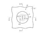
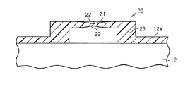
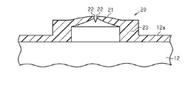
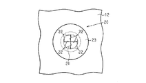
- FIG. 3 is a cross-sectional view of a ventilation portion along line AA in FIG. 2. Sectional drawing of the ventilation part at the time of closing along the BB line of FIG. Sectional drawing of the ventilation part at the time of opening along the BB line of FIG. The top view of the 1st modification of a ventilation part. Sectional drawing of the 2nd modification of a ventilation part. Sectional drawing of the 3rd modification of a ventilation part.
- the wire harness 1 will be described with reference to FIGS.
- the wire harness 1 electrically connects two or more electric devices.
- the electric device include a vehicle drive motor, motors for various electrical components mounted on the vehicle, a power supply device, and the like.
- the wire harness 1 includes one or more electric wires 2 coated with a resin, a connector 3 attached to an end portion of the electric wires 2, and a protective tube 10 that protects the electric wires 2.
- the protective tube 10 protects the electric wire 2 from flying objects and water. For example, when the electric wire 2 is mounted on a vehicle without a protective tube, a stepping stone (flying object) may hit the electric wire 2 during traveling and the coating may be damaged. In order to suppress such damage to the electric wire 2, the electric wire 2 is protected by a protective tube 10.
- the protective tube 10 includes a tubular exterior material 11 that covers the electric wire 2, and a tubular waterproof cover 12 that is attached so as to be spanned between the connector 3 and the exterior material 11.
- the waterproof cover 12 is attached to the end portion so as to cover the end portion of the exterior material 11.
- the waterproof cover 12 covers a portion of the electric wire 2 that is not covered with the exterior material 11.
- the waterproof cover 12 is also called a grommet.
- the exterior material 11 is composed of, for example, a flexible corrugated tube or a rigid tube that is difficult to bend.
- the exterior material 11 and the waterproof cover 12 are fastened with a band, tape, or the like. Further, the waterproof cover 12 and the connector 3 are fastened with a band, a tape or the like.
- the waterproof cover 12 is made of rubber or elastomer at least at a portion to be fastened with a band or tape.
- the type of rubber and the type of elastomer are not limited, but those having high chemical resistance, for example, resistance to an antifreezing agent (for example, calcium chloride) are preferable.
- the entire waterproof cover 12 is formed of an elastomer (for example, a polyamide-based elastomer).
- the protective tube 10 is provided with a ventilation portion 20 for adjusting the internal pressure.
- the exterior material 11 and the waterproof cover 12 are fastened in a watertight manner, and the waterproof cover 12 and the connector 3 are fastened in a watertight manner, so that the inside and the outside of the protective tube 10 are isolated.
- the protective tube 10 expands or deforms, and its deterioration may increase. Therefore, in order to suppress such an increase in pressure difference, the protective tube 10 is provided with a ventilation portion 20.
- the vent 20 allows air to pass through and prevents water from entering.
- the ventilation part 20 has a pair of contact surfaces 22.
- the pair of contact surfaces 22 are provided so as to penetrate the wall 12a constituting the waterproof cover 12 and come into contact with each other. Specifically, the pair of contact surfaces 22 are in close contact with each other so as to be separated from each other.
- the contact surface 22 has an outer edge 22 a that is a boundary with the outer surface of the wall 12 a that constitutes the waterproof cover 12, and an inner edge 22 b that is a boundary between the inner surface of the wall 12 a that constitutes the waterproof cover 12.
- the first end 22c is one end connecting the outer edge 22a and the inner edge 22b
- the second end 22d is the other end connecting the outer edge 22a and the inner edge 22b.
- the first end 22c and the second end 22d extend in the thickness direction of the wall 12a.
- the distance between the outer edge 22a and the inner edge 22b, that is, the thinnest part of the width dimension of the contact surface 22 is thick enough to prevent water from entering.
- Such a contact surface 22 is formed, for example, by cutting the wall 12a.
- the pair of contact surfaces 22 are separated by the ventilation portion 20 being deformed based on the occurrence of a pressure difference between the inside and outside of the protective tube 10. That is, a portion including the contact surface 22 (hereinafter, “contact portion 21”, a portion surrounded by a two-dot chain line in FIG. 2) is elastically deformed based on the pressure difference.
- the contact portion 21 is a part of the wall 12a of the waterproof cover 12.
- the contact portion 21 is thinner in the waterproof cover 12 than the portion around the contact portion 21. That is, the contact portion 21 is more easily bent than the portion around the contact portion 21. Thereby, the air permeability in the ventilation part 20 is improved.
- the thickness of the contact portion 21 gradually decreases toward the contact surface 22 in a direction intersecting the contact surface 22 (see FIG. 4).
- the ventilation part 20 is provided with an annular thick part 23 surrounding the ventilation part 20.
- the thickness LY of the thick portion 23 is larger than the thickness LA of the outer wall 12 a of the thick portion 23 in the waterproof cover 12.
- the width LX of the thick portion 23 is larger than the thickness LA of the outer wall 12a of the thick portion 23 (see FIG. 3).
- the thick part 23 is a part of the wall 12 a of the waterproof cover 12.
- the waterproof cover 12 of the protective tube 10 may be bent when the wire harness 1 is installed. If the waterproof cover 12 is bent with a large curvature, the ventilation portion 20 may be deformed, the contact surface 22 may be separated, and the ventilation portion 20 may be left open. Since the thick portion 23 is annular, the thick portion 23 and its internal shape are not easily deformed even by such deformation (for example, bending deformation) of the contact portion 21. Thereby, it is suppressed that the contact surface 22 separates.
- action of the ventilation part 20 is demonstrated.
- the internal pressure of the protective tube 10 becomes higher than the external pressure, and the protective tube 10 expands.
- the protective tube 10 expands, in particular, the waterproof cover 12 that expands more easily than the exterior material 11 expands. Since the contact portion 21 is thin, it is particularly easily deformed. For this reason, the contact part 21 deform
- the waterproof cover 12 has a ventilation part 20 through which air can pass.
- the ventilation part 20 has a pair of contact surfaces 22.
- the pair of contact surfaces 22 are provided so as to penetrate the wall 12a constituting the waterproof cover 12 and come into contact with each other.
- the pair of contact surfaces 22 are separated from each other by the deformation of the ventilation portion 20 based on the occurrence of a pressure difference between the inside and the outside of the protective tube 10. According to this configuration, the atmospheric pressure in the protective tube 10 can be adjusted with fewer components than in the conventional structure.
- the contact portion 21 including the contact surface 22 is thinner than the portion around the contact portion 21 in the waterproof cover 12. According to this structure, since the contact part 21 is easy to deform
- the waterproof cover 12 is provided with a thick portion 23 surrounding the ventilation portion 20.
- the thickness LY of the thick portion 23 is larger than the thickness LA of the outer wall 12 a of the thick portion 23 in the waterproof cover 12.
- the ventilation portion 20 may be deformed and the pair of contact surfaces 22 may be separated.
- the ventilation portion 20 in the thick portion 23 is deformed as the periphery of the ventilation portion 20 is deformed. Is suppressed.
- the pair of contact surfaces 22 are separated from each other, and the ventilation portion 20 is not easily opened and released.
- the waterproof cover 12 is made of rubber or elastomer. According to this configuration, since the exterior material 11 and the waterproof cover 12 can be brought into close contact with each other, it is possible to prevent water from entering from the gap between the exterior material 11 and the waterproof cover 12.
- the wire harness 1 includes a protective tube 10 including any one of the waterproof covers 12 and an electric wire 2 inserted through the protective tube 10.
- the wire harness 1 has a smaller number of parts than a wire harness having a conventional structure.
- the structure of the waterproof cover 12 is not limited to the above embodiment.
- the ventilation part 20 is provided in the waterproof cover 12 which connects between the exterior material 11 and the connector 3
- the waterproof cover 12 in which the ventilation part 20 is provided is not limited to this.
- a waterproof cover 12 having three crotch is provided at a branch portion of the electric wires 2.
- Such a waterproof cover 12 is connected to the exterior material 11.
- This type of waterproof cover 12 may also be provided with a ventilation portion 20.
- the ventilation part 20 has 1 set of a pair of contact surfaces 22, the number of sets of a pair of contact surfaces 22 is not limited. As shown in FIG. 6, for example, the ventilation portion 20 can include four pairs of contact surfaces 22. The four sets of contact surfaces 22 are arranged in a + character shape, for example. As another form, the ventilation portion 20 can include two pairs of contact surfaces 22. In this case, the pair of contact surfaces 22 of each group are arranged in parallel (not shown).
- the thick part 23 surrounding the ventilation part 20 is provided so that it may protrude outward in the wall 12a of the waterproof cover 12, the thick part 23 is provided so that it may protrude inward. Also good.
- the thick portion 23 may be provided so as to protrude both inward and outward in the wall 12 a of the waterproof cover 12.
- the pair of contact surfaces 22 may be provided on the annular thick portion 23.
- the thick part 23 constitutes a part of the wall 12a.
- the pair of contact surfaces 22 are provided so as to penetrate through the thick portion 23 as the wall 12 a that partitions the inside and outside of the waterproof cover 12.
- the waterproof cover 12 shown in the figure is sometimes called a water-tight sealing sleeve (a liquid-tight sealing sleeve).
- the illustrated vent 20 may be referred to as a non-electric ventilator.
- the illustrated contact portion 21 and contact surface 22 may be referred to as an elastically deformable valve body and / or a plurality of leaflets.
- the contact portion 21 in FIG. 8 may be referred to as a flap valve
- the ventilation portion 20 in FIG. 8 may be referred to as a flap type ventilator.
- the valve body closes the ventilator when the pressure difference between the inside and the outside of the water-stopping seal sleeve is within a predetermined pressure range, and the pressure difference between the inside and the outside of the water-stopping seal sleeve is the predetermined pressure.
- the ventilator is configured to be elastically deformed when it is out of the pressure range. By the elastic deformation of the valve body, the pressure difference between the inside and the outside of the water-stop seal sleeve can be restored to a predetermined pressure range without consuming electric power.
- the exterior material 11 that may be a corrugated pipe may be bent or compressed or elongated in the longitudinal direction so as to match the routing path.
- the atmospheric pressure difference between the inside and the outside of the water-proof seal sleeve may exceed a predetermined pressure range.
- the valve body is elastically deformed by this atmospheric pressure difference, and by eliminating the atmospheric pressure difference, the repulsive force, that is, the resistance to the operation of matching the exterior material 11 with the wiring path is reduced, and the wiring process of the wire harness 1 is facilitated. .
- the waterproof cover (12) of some mounting examples includes at least one electric wire (2), an electric wire protection tube (11) for protecting the at least one electric wire (2), and the at least one electric wire.
- the wire harness (1) is formed in cooperation with the electrical connector (3) connected to the ends of the two electric wires (2), and the waterproof cover (12) A waterproof seal sleeve (12) that covers a connection portion between the at least one electric wire (2) and the electrical connector (3) and connects the electric wire protection tube (11) and the electrical connector (3) in-line.
- the ventilator (20) includes at least one valve body (22) that can be elastically deformed, and the at least one valve body (22) includes an inside and an outside of the water-stop seal sleeve (12).
- the ventilator (20) is closed when the atmospheric pressure difference is within a predetermined pressure range, and is elastically deformed when the atmospheric pressure difference between the inside and outside of the water-tight seal sleeve (12) is outside the predetermined pressure range. And configured to open the ventilator (20).
- the at least one valve element (22) is a plurality of leaflets.
- the at least one valve element (22) is a flap.
- the waterproof cover (12) is a one-piece product made of weathering material including the water-proof seal sleeve (12) and the ventilator (20).
- SYMBOLS 1 Wire harness, 2 ... Electric wire, 3 ... Connector, 10 ... Protective tube, 11 ... Exterior material, 12 ... Waterproof cover, 12a ... Wall, 20 ... Ventilation part, 21 ... Contact part, 22 ... Contact surface, 22a ... Outer edge 22b ... inner edge, 22c ... first end, 22d ... second end, 23 ... thick part, LA ... wall thickness, LY ... thick part thickness, LX ... width length.
Landscapes
- Engineering & Computer Science (AREA)
- Mechanical Engineering (AREA)
- Architecture (AREA)
- Civil Engineering (AREA)
- Structural Engineering (AREA)
- Details Of Indoor Wiring (AREA)
- Connector Housings Or Holding Contact Members (AREA)
Abstract
電線を保護する保護管の外装材に接続される防水カバーは、空気が通過可能な通気部20を有する。通気部20は、防水カバーを構成する壁を貫くように設けられて接触し合う一対の接触面22,22を有する。保護管の内外の気圧差が生じることに基づいて通気部20が変形することにより一対の接触面22,22が離間する。
Description
本発明は、電線を保護する保護管における防水カバー、及び防水カバーを備えるワイヤーハーネスに関する。
電線は、水または粉塵等からの保護のため、保護管で覆われる。電線は、様々な態様で配索されるため、保護管は、構造の異なる複数種の管の連結体として構成される。例えば、保護管は、電線の端部を除く中間部を保護する外装材と、外装材と電線の端部のコネクタとの間を保護するゴム製の防水カバーとを備える。保護管が電線の両端のコネクタ間の部分を密封するため、温度や気圧変化等により、保護管の内外圧力差が拡大することがある。内外圧力差の拡大を抑制するため、防水カバーには通気装置が設けられる。通気装置には、通気性をもちながら、防水・防塵機能を持つ通気フィルタが設けられている(特許文献1参照)。
ところで、保護管の防水カバーにこのような通気装置を設けると部品点数が増大する。このような観点から、従来の防水カバーには改善の余地がある。
(1)上記課題を解決する防水カバーは、電線を保護する保護管の外装材に接続される防水カバーであって、空気が通過可能な通気部を有し、前記通気部は、前記防水カバーを構成する壁を貫くように設けられて接触し合う一対の接触面を有し、前記保護管の内外の気圧差が生じることに基づいて前記通気部が変形することにより一対の前記接触面が離間する。
この構成によれば、従来構造に比べて少ない部品構成で、保護管内の気圧を調整できる。
(2)上記防水カバーにおいて、前記接触面を含む接触部は、前記防水カバーにおいて前記接触部周辺の部分よりも薄い。
(2)上記防水カバーにおいて、前記接触面を含む接触部は、前記防水カバーにおいて前記接触部周辺の部分よりも薄い。
この構成によれば、接触部がその周辺に比べて変形し易いため、一対の接触面を離間させることが可能な気圧差を小さくできる。
(3)上記防水カバーにおいて、前記通気部を囲む肉厚部が設けられ、前記肉厚部の厚さは、前記防水カバーにおいて前記肉厚部の外側の壁の厚さよりも大きい。
(3)上記防水カバーにおいて、前記通気部を囲む肉厚部が設けられ、前記肉厚部の厚さは、前記防水カバーにおいて前記肉厚部の外側の壁の厚さよりも大きい。
防水カバーが曲げられると通気部が変形して一対の接触面が離間する虞がある。この点、上記構成によれば、通気部は肉厚部で囲まれているため、通気部の周囲が変形することに伴って肉厚部内にある通気部が変形することが抑制される。
(4)上記防水カバーはゴム製またはエラストマ製である。
この構成によれば、外装材と防水カバーとを密着させることができるため、外装材と防水カバーとの間の隙間から水が侵入することを抑制できる。
この構成によれば、外装材と防水カバーとを密着させることができるため、外装材と防水カバーとの間の隙間から水が侵入することを抑制できる。
(5)課題を解決するワイヤーハーネスは、上記いずれかの防水カバーを含む保護管と、前記保護管に挿通する電線とを備える。
本発明のいくつかの態様に従う防水カバー及びワイヤーハーネスは、従来に比べて、少ない部品点数で構成できる。
本発明のいくつかの態様に従う防水カバー及びワイヤーハーネスは、従来に比べて、少ない部品点数で構成できる。
図1~図5を参照して、ワイヤーハーネス1について説明する。
ワイヤーハーネス1は、2個または3個以上の電気装置を電気的に繋ぐ。例えば、電気装置としては、車両駆動モータ、車両に搭載される各種電装品のモータ、電源装置、等が挙げられる。
ワイヤーハーネス1は、2個または3個以上の電気装置を電気的に繋ぐ。例えば、電気装置としては、車両駆動モータ、車両に搭載される各種電装品のモータ、電源装置、等が挙げられる。
図1に示されるように、ワイヤーハーネス1は、樹脂で被覆された1または複数の電線2と、電線2の端部に取り付けられるコネクタ3と、電線2を保護する保護管10とを備える。保護管10は、飛翔物や水等から電線2を保護する。例えば、保護管無しで電線2が車両に搭載されると、走行時に飛び石(飛翔物)が電線2に当たり被膜に傷が付くおそれがある。このような電線2の損傷等を抑制する目的で、電線2は、保護管10で保護される。
保護管10は、電線2を覆う管状の外装材11と、コネクタ3と外装材11との間に掛け渡されるように取り付けられた管状の防水カバー12とを備える。防水カバー12は、外装材11の端部を被覆するようその端部に取り付けられる。この防水カバー12は、電線2において外装材11に覆われない部分を覆う。なお、防水カバー12は、グロメットとも呼ばれる。外装材11は、例えば、可撓性を有するコルゲート管や撓み難い剛性管により構成される。外装材11と防水カバー12とはバンドやテープ等で締結される。また、防水カバー12とコネクタ3とはバンドやテープ等で締結される。
防水カバー12は、少なくともバンドやテープ等で締結される部分がゴムまたはエラストマで構成される。ゴムの種類及びエラストマの種類は限定されないが、耐薬品性、例えば凍結防止剤(例えば塩化カルシウム)に対する耐性が高いものが好ましい。実施形態では、防水カバー12全体がエラストマ(例えば、ポリアミド系エラストマ)で形成される。
図2に示されるように、保護管10には、内圧を調整するための通気部20が設けられる。ここで、保護管10において外装材11と防水カバー12とは、水密に締結され、かつ防水カバー12とコネクタ3とが水密に締結されており、保護管10の内外が隔離されている。このため、保護管10の内外において圧力差が拡大するおそれがあり、内外圧力差が拡大すると、保護管10が膨張または変形し、その劣化が増進するおそれがある。そこで、このような圧力差の拡大を抑制するために、保護管10には通気部20が設けられている。
通気部20は、空気が通過可能であり、水の侵入を阻止する。通気部20は、一対の接触面22を有する。一対の接触面22は、防水カバー12を構成する壁12aを貫くように設けられて接触し合う。具体的には、一対の接触面22は、離間可能に水密に密着する。
図3に示されるように、接触面22は、防水カバー12を構成する壁12aの外面との境界である外縁22aと、防水カバー12を構成する壁12aの内面との境界である内縁22bと、外縁22aと内縁22bとを接続する一方端の第1端22cと、外縁22aと内縁22bとを接続する他方端の第2端22dとを有する。第1端22c及び第2端22dは、壁12aの厚さ方向に延びる。外縁22aと内縁22bとの間の距離すなわち接触面22の幅寸法の最も薄いところは、水の侵入を阻止することができる程度に厚い。このような接触面22は、例えば、壁12aを切り裂くようにして形成される。
このような一対の接触面22は、保護管10の内外の気圧差が生じることに基づいて通気部20が変形して離間する。すなわち、接触面22を含む部分(以下、「接触部21」。図2の2点鎖線で囲まれた部分。)は、気圧差に基づいて弾性変形する。なお、接触部21は、防水カバー12の壁12aの一部分である。
好ましくは、接触部21は、防水カバー12において接触部21周辺の部分よりも薄い。すなわち、接触部21が、接触部21周辺の部分よりも撓み易くなっている。これにより、通気部20における空気の通気性を向上させている。例えば、接触部21の厚みは、接触面22に交差する方向において接触面22に向かって漸次小さくなる(図4参照)。
更に好ましくは、通気部20には、通気部20を囲む環状の肉厚部23が設けられる。肉厚部23の厚さLYは、防水カバー12において肉厚部23の外側の壁12aの厚さLAよりも大きい。また、肉厚部23の幅長LXは、肉厚部23の外側の壁12aの厚さLAよりも大きい(図3参照)。なお、肉厚部23は、防水カバー12の壁12aの一部である。
保護管10の防水カバー12は、ワイヤーハーネス1の設置において曲げられることがある。防水カバー12が大きい曲率で曲げられると、通気部20が変形し、接触面22が離間し通気部20が開口し放しになる虞がある。肉厚部23は環状であるため、このような接触部21の変形(例えば、曲げ変形)によっても、肉厚部23及びその内部の形状が変形し難い。これによって、接触面22が離間することが抑制される。
図4及び図5を参照して、通気部20の作用を説明する。
電線2に電流が流れて保護管10内の空気が加熱されると、保護管10の内圧が外圧よりも高くなり保護管10が膨張する。例えば、ワイヤーハーネス1が車両駆動用モータのインバータに接続される場合、電線2に高圧交流が印加されるため、電線2が高温になり、空気が加熱され易い。保護管10が膨張するときは、特に、外装材11よりも膨張し易い防水カバー12が膨張する。接触部21は肉薄であるため、特に変形し易い。このため、接触部21が変形して、接触面22が離間する。これにより、保護管10内の空気が排出され、保護管10の内外圧力差が小さくなる。内外圧力差が小さくなると、接触部21が元の形状に戻り、接触面22が閉じられる。
電線2に電流が流れて保護管10内の空気が加熱されると、保護管10の内圧が外圧よりも高くなり保護管10が膨張する。例えば、ワイヤーハーネス1が車両駆動用モータのインバータに接続される場合、電線2に高圧交流が印加されるため、電線2が高温になり、空気が加熱され易い。保護管10が膨張するときは、特に、外装材11よりも膨張し易い防水カバー12が膨張する。接触部21は肉薄であるため、特に変形し易い。このため、接触部21が変形して、接触面22が離間する。これにより、保護管10内の空気が排出され、保護管10の内外圧力差が小さくなる。内外圧力差が小さくなると、接触部21が元の形状に戻り、接触面22が閉じられる。
本実施形態に係る防水カバー12及びワイヤーハーネス1について作用及び効果を説明する。
(1)防水カバー12は、空気が通過可能な通気部20を有する。通気部20は、一対の接触面22を有する。一対の接触面22は、防水カバー12を構成する壁12aを貫くように設けられて接触し合う。保護管10の内外の気圧差が生じることに基づいて通気部20が変形することにより、一対の接触面22は離間する。この構成によれば、従来構造に比べて少ない構成部品で、保護管10内の気圧を調整できる。
(1)防水カバー12は、空気が通過可能な通気部20を有する。通気部20は、一対の接触面22を有する。一対の接触面22は、防水カバー12を構成する壁12aを貫くように設けられて接触し合う。保護管10の内外の気圧差が生じることに基づいて通気部20が変形することにより、一対の接触面22は離間する。この構成によれば、従来構造に比べて少ない構成部品で、保護管10内の気圧を調整できる。
また、従来構造では、通気装置を防水カバーに取り付ける必要があった。これに対し、本構成によれば、防水カバー12に通気部20が一体に形成されているため、その通気部20を防水カバー12に取り付ける作業を省略することができる。
(2)接触面22を含む接触部21は、防水カバー12において接触部21周辺の部分よりも薄い。この構成によれば、接触部21がその周辺(すなわち接触部21の周囲)に比べて変形し易いため、一対の接触面22を離間させることが可能な気圧差を小さくできる。
(3)防水カバー12には、通気部20を囲む肉厚部23が設けられる。肉厚部23の厚さLYは、防水カバー12において肉厚部23の外側の壁12aの厚さLAよりも大きい。
防水カバー12が曲げられると通気部20が変形して一対の接触面22が離間する虞がある。この点、上記構成によれば、通気部20は肉厚部23で囲まれているため、通気部20の周囲が変形することに伴って肉厚部23内にある通気部20が変形することが抑制される。これにより、一対の接触面22が離間し通気部20が開口し放し状態になることが起こり難くなる。
(4)上記防水カバー12はゴム製またはエラストマ製である。この構成によれば、外装材11と防水カバー12とを密着させることができるため、外装材11と防水カバー12との間の隙間から水が侵入することを抑制できる。
(5)ワイヤーハーネス1は、上記いずれかの防水カバー12を含む保護管10と、保護管10に挿通する電線2とを備える。このワイヤーハーネス1は、従来構造のワイヤーハーネスに比べて、部品点数が少ない。
<その他の実施形態>
上記防水カバー12の構造は、上記実施形態に限定されない。
・実施形態では、通気部20は、外装材11とコネクタ3との間を接続する防水カバー12に設けられるが、通気部20が設けられる防水カバー12は、これに限定されない。例えば、束ねられた複数の電線2が2つに分けられて別々の方向に配索される場合、電線2の分岐部分に3つ股の防水カバー12が設けられる。このような防水カバー12は外装材11に接続されるものである。この種の防水カバー12にも通気部20が設けられ得る。
上記防水カバー12の構造は、上記実施形態に限定されない。
・実施形態では、通気部20は、外装材11とコネクタ3との間を接続する防水カバー12に設けられるが、通気部20が設けられる防水カバー12は、これに限定されない。例えば、束ねられた複数の電線2が2つに分けられて別々の方向に配索される場合、電線2の分岐部分に3つ股の防水カバー12が設けられる。このような防水カバー12は外装材11に接続されるものである。この種の防水カバー12にも通気部20が設けられ得る。
・上記実施形態では、通気部20は、一対の接触面22を1組有するが、一対の接触面22の組数は限定されない。
図6に示されるように、例えば、通気部20は、一対の接触面22を4組備え得る。4組の接触面22は、例えば、+字状に配置される。また、別の形態として、通気部20は、一対の接触面22を2組備え得る。この場合は、各組の一対の接触面22は、平行に配置される(図示省略)。
図6に示されるように、例えば、通気部20は、一対の接触面22を4組備え得る。4組の接触面22は、例えば、+字状に配置される。また、別の形態として、通気部20は、一対の接触面22を2組備え得る。この場合は、各組の一対の接触面22は、平行に配置される(図示省略)。
・上記実施形態では、通気部20を囲む肉厚部23は、防水カバー12の壁12aにおいて外方に突出するように設けられるが、肉厚部23は、内方に突出するように設けてもよい。
また、図7に示されるように、肉厚部23は、防水カバー12の壁12aにおいて内方及び外方の双方に突出するように設けてもよい。
・図8に示されるように、一対の接触面22は、環状の肉厚部23に設けてもよい。肉厚部23は、壁12aの一部を構成する。一対の接触面22は、防水カバー12の内外を仕切る壁12aとしての肉厚部23を貫くように設けられる。
・図8に示されるように、一対の接触面22は、環状の肉厚部23に設けてもよい。肉厚部23は、壁12aの一部を構成する。一対の接触面22は、防水カバー12の内外を仕切る壁12aとしての肉厚部23を貫くように設けられる。
・図示した防水カバー12は、止水性シールスリーブ(a liquid-tight sealing sleeve)と呼称することがある。図示した通気部20は非電動式のベンチレータと呼称することがある。図示した接触部21及び接触面22は、弾性変形可能な弁体、および/または複数の小葉片(leaflets)と呼称することがある。とりわけ図8の接触部21はフラップ弁と呼称することがあり、図8の通気部20はフラップ式ベンチレータと呼称することがある。いずれの例においても、弁体は、止水性シールスリーブの内部と外部との気圧差が所定の圧力範囲にあるときにベンチレータを閉じ、止水性シールスリーブの内部と外部との気圧差が前記所定の圧力範囲から外れたときに弾性変形してベンチレータを開くように構成される。弁体の弾性変形によって、止水性シールスリーブの内部と外部との気圧差を、電力を消費することなく所定の圧力範囲に復帰させることができる。例えば、ワイヤーハーネス1を自動車に配索する工程において、コルゲート管であり得る外装材11を、配索経路に合致するように曲げたり長手方向に圧縮または伸長させることがある。こうした外装材11の変形によって止水性シールスリーブの内部と外部との気圧差が所定の圧力範囲を超えることが起こり得る。この気圧差によって弁体が弾性変形し、気圧差を解消させることによって、外装材11を配索経路に合致させる作業に対する反発力すなわち抵抗が低下し、ワイヤーハーネス1の配索工程が容易になる。
本開示は以下の実装例を包含する。限定のためでなく理解の補助として実施形態の構成要素の参照符号を付した。
[付記1]いくつかの実装例の防水カバー(12)は、少なくとも一つの電線(2)と、前記少なくとも一つの電線(2)を保護するための電線保護管(11)と、前記少なくとも一つの電線(2)の端部に接続される電気的コネクタ(3)と協働してワイヤーハーネス(1)を形成するように構成されており、前記防水カバー(12)は、
前記少なくとも一つの電線(2)と前記電気的コネクタ(3)との接続部分を覆い、前記電線保護管(11)と前記電気的コネクタ(3)とをインラインに接続する止水性シールスリーブ(12)と、
前記止水性シールスリーブ(12)に設けられた非電動式のベンチレータ(20)とを備える。
[付記1]いくつかの実装例の防水カバー(12)は、少なくとも一つの電線(2)と、前記少なくとも一つの電線(2)を保護するための電線保護管(11)と、前記少なくとも一つの電線(2)の端部に接続される電気的コネクタ(3)と協働してワイヤーハーネス(1)を形成するように構成されており、前記防水カバー(12)は、
前記少なくとも一つの電線(2)と前記電気的コネクタ(3)との接続部分を覆い、前記電線保護管(11)と前記電気的コネクタ(3)とをインラインに接続する止水性シールスリーブ(12)と、
前記止水性シールスリーブ(12)に設けられた非電動式のベンチレータ(20)とを備える。
[付記2]前記ベンチレータ(20)は、弾性変形可能な少なくとも一つの弁体(22)を含み、前記少なくとも一つの弁体(22)は、前記止水性シールスリーブ(12)の内部と外部との気圧差が所定の圧力範囲にあるときに前記ベンチレータ(20)を閉じ、前記止水性シールスリーブ(12)の内部と外部との気圧差が前記所定の圧力範囲外になった時に弾性変形して前記ベンチレータ(20)を開くように構成される。
[付記3]いくつかの実装例では、前記少なくとも一つの弁体(22)は複数の小葉片である。
[付記4]いくつかの実装例では、前記少なくとも一つの弁体(22)は、フラップである。
[付記4]いくつかの実装例では、前記少なくとも一つの弁体(22)は、フラップである。
[付記5]いくつかの実装例では、前記防水カバー(12)は、前記止水性シールスリーブ(12)と前記ベンチレータ(20)とを含む、対候性材料製のワンピース品である。
本発明がその技術的思想から逸脱しない範囲で他の特有の形態で具体化されてもよいということは当業者にとって明らかであろう。例えば、実施形態(あるいはその1つ又は複数の態様)において説明した部品のうちの一部を省略したり、いくつかの部品を組合せてもよい。本発明の範囲は、添付の請求の範囲を参照して、請求の範囲が権利を与えられる均等物の全範囲と共に確定されるべきである。
1…ワイヤーハーネス、2…電線、3…コネクタ、10…保護管、11…外装材、12…防水カバー、12a…壁、20…通気部、21…接触部、22…接触面、22a…外縁、22b…内縁、22c…第1端、22d…第2端、23…肉厚部、LA…壁の厚さ、LY…肉厚部の厚さ、LX…幅長。
Claims (5)
- 電線を保護する保護管の外装材に接続される防水カバーであって、
空気が通過可能な通気部を有し、
前記通気部は、前記防水カバーを構成する壁を貫くように設けられて接触し合う一対の接触面を有し、前記保護管の内外の気圧差が生じることに基づいて前記通気部が変形することにより一対の前記接触面が離間する
ことを特徴とする防水カバー。 - 請求項1に記載の防水カバーにおいて、
前記接触面を含む接触部は、前記防水カバーにおいて前記接触部周辺の部分よりも薄いことを特徴とする防水カバー。 - 請求項1または2に記載の防水カバーにおいて、
前記通気部を囲む肉厚部が設けられ、前記肉厚部の厚さは、前記防水カバーにおいて前記肉厚部の外側の前記壁の厚さよりも大きいことを特徴とする防水カバー。 - 請求項1~3のいずれか一項に記載の防水カバーにおいて、
前記防水カバーはゴム製またはエラストマ製であることを特徴とする防水カバー。 - 請求項1~4のいずれか一項に記載の防水カバーを含む保護管と、前記保護管に挿通する電線とを備えることを特徴とするワイヤーハーネス。
Priority Applications (2)
| Application Number | Priority Date | Filing Date | Title |
|---|---|---|---|
| US16/474,974 US10886719B2 (en) | 2017-01-20 | 2018-01-12 | Waterproof cover and wire harness |
| CN201880005696.3A CN110235325B (zh) | 2017-01-20 | 2018-01-12 | 防水盖及线束 |
Applications Claiming Priority (2)
| Application Number | Priority Date | Filing Date | Title |
|---|---|---|---|
| JP2017008598A JP6696446B2 (ja) | 2017-01-20 | 2017-01-20 | 防水カバー及びワイヤーハーネス |
| JP2017-008598 | 2017-01-20 |
Publications (1)
| Publication Number | Publication Date |
|---|---|
| WO2018135388A1 true WO2018135388A1 (ja) | 2018-07-26 |
Family
ID=62907999
Family Applications (1)
| Application Number | Title | Priority Date | Filing Date |
|---|---|---|---|
| PCT/JP2018/000587 Ceased WO2018135388A1 (ja) | 2017-01-20 | 2018-01-12 | 防水カバー及びワイヤーハーネス |
Country Status (4)
| Country | Link |
|---|---|
| US (1) | US10886719B2 (ja) |
| JP (1) | JP6696446B2 (ja) |
| CN (1) | CN110235325B (ja) |
| WO (1) | WO2018135388A1 (ja) |
Cited By (1)
| Publication number | Priority date | Publication date | Assignee | Title |
|---|---|---|---|---|
| CN111791696A (zh) * | 2019-04-03 | 2020-10-20 | 株式会社电装 | 车辆控制设备 |
Families Citing this family (3)
| Publication number | Priority date | Publication date | Assignee | Title |
|---|---|---|---|---|
| JP7301907B2 (ja) * | 2021-06-14 | 2023-07-03 | 矢崎総業株式会社 | コネクタ及びコネクタ付き電線 |
| FR3132397A1 (fr) * | 2022-02-03 | 2023-08-04 | Psa Automobiles Sa | Dispositif electrique protege contre la formation de court-circuit electriques dus a un choc |
| DE102023004029A1 (de) * | 2023-10-06 | 2025-04-10 | eddylab GmbH | lnduktiver Sensor mit hermetisch dichter Steckverbindung |
Citations (2)
| Publication number | Priority date | Publication date | Assignee | Title |
|---|---|---|---|---|
| JPH0273151U (ja) * | 1988-08-12 | 1990-06-04 | ||
| JP2013241143A (ja) * | 2012-05-22 | 2013-12-05 | Sumitomo Wiring Syst Ltd | 防水カバー |
Family Cites Families (5)
| Publication number | Priority date | Publication date | Assignee | Title |
|---|---|---|---|---|
| JPH0935807A (ja) * | 1995-07-19 | 1997-02-07 | Sumitomo Wiring Syst Ltd | 防水コネクタ |
| JP2004512875A (ja) * | 2000-11-02 | 2004-04-30 | コーニンクレッカ フィリップス エレクトロニクス エヌ ヴィ | 装置の防水ハウジング |
| JP2002213631A (ja) * | 2001-01-18 | 2002-07-31 | Shinko Pantec Co Ltd | 給排気シートとその給排気シートを用いた容器並びにその給排気シートを用いた容器内外の圧力の均等化方法。 |
| JP2003294047A (ja) * | 2002-04-01 | 2003-10-15 | Nsk Ltd | 鉄道車両用軸受装置 |
| CN1820955A (zh) * | 2006-03-23 | 2006-08-23 | 珠海天威技术开发有限公司 | 压差阀及墨盒 |
-
2017
- 2017-01-20 JP JP2017008598A patent/JP6696446B2/ja not_active Expired - Fee Related
-
2018
- 2018-01-12 US US16/474,974 patent/US10886719B2/en not_active Expired - Fee Related
- 2018-01-12 WO PCT/JP2018/000587 patent/WO2018135388A1/ja not_active Ceased
- 2018-01-12 CN CN201880005696.3A patent/CN110235325B/zh not_active Expired - Fee Related
Patent Citations (2)
| Publication number | Priority date | Publication date | Assignee | Title |
|---|---|---|---|---|
| JPH0273151U (ja) * | 1988-08-12 | 1990-06-04 | ||
| JP2013241143A (ja) * | 2012-05-22 | 2013-12-05 | Sumitomo Wiring Syst Ltd | 防水カバー |
Cited By (2)
| Publication number | Priority date | Publication date | Assignee | Title |
|---|---|---|---|---|
| CN111791696A (zh) * | 2019-04-03 | 2020-10-20 | 株式会社电装 | 车辆控制设备 |
| CN111791696B (zh) * | 2019-04-03 | 2025-10-03 | 株式会社电装 | 车辆控制设备 |
Also Published As
| Publication number | Publication date |
|---|---|
| US20190334339A1 (en) | 2019-10-31 |
| CN110235325A (zh) | 2019-09-13 |
| JP2018117497A (ja) | 2018-07-26 |
| JP6696446B2 (ja) | 2020-05-20 |
| US10886719B2 (en) | 2021-01-05 |
| CN110235325B (zh) | 2020-09-15 |
Similar Documents
| Publication | Publication Date | Title |
|---|---|---|
| CN106143354B (zh) | 电线保护部件 | |
| JP6248899B2 (ja) | ワイヤハーネスのシール構造 | |
| CN110785821B (zh) | 线束 | |
| CN105720530B (zh) | 护线套及使用护线套的密封结构 | |
| US11242016B2 (en) | Grommet and wire harness | |
| WO2018135388A1 (ja) | 防水カバー及びワイヤーハーネス | |
| JP6635308B2 (ja) | 防水部材 | |
| CN111917082B (zh) | 索环以及线束 | |
| CN112740495B (zh) | 线束 | |
| CN111619471A (zh) | 索环以及线束 | |
| EP3702221B1 (en) | Grommet and wire harness | |
| JP6422257B2 (ja) | グロメット及びこのグロメットを用いたワイヤハーネス | |
| CN110178278B (zh) | 通气部件以及电线束 | |
| CN203685491U (zh) | 一种管缆防雨罩 | |
| JP6835024B2 (ja) | ワイヤハーネス | |
| JP2019179736A (ja) | ワイヤハーネス | |
| JP5733123B2 (ja) | グロメット | |
| JP7621921B2 (ja) | グロメットユニット及び止水構造 | |
| JP2016062675A (ja) | ワイヤーハーネス | |
| AU2017100831A4 (en) | Scratch-proof protection structure for a leading-out wire of a motor | |
| JP6274940B2 (ja) | 配線用ダストカバー及び配線用ダストカバー組み付け方法 | |
| AU2017100833A4 (en) | Highly-sealed protection structure for a leading-out wire of a motor | |
| AU2017100832A4 (en) | Water-proof protection structure for a leading-out wire of a motor |
Legal Events
| Date | Code | Title | Description |
|---|---|---|---|
| 121 | Ep: the epo has been informed by wipo that ep was designated in this application |
Ref document number: 18741190 Country of ref document: EP Kind code of ref document: A1 |
|
| NENP | Non-entry into the national phase |
Ref country code: DE |
|
| 122 | Ep: pct application non-entry in european phase |
Ref document number: 18741190 Country of ref document: EP Kind code of ref document: A1 |