WO2018123655A1 - 熱変色性筆記具 - Google Patents
熱変色性筆記具 Download PDFInfo
- Publication number
- WO2018123655A1 WO2018123655A1 PCT/JP2017/045103 JP2017045103W WO2018123655A1 WO 2018123655 A1 WO2018123655 A1 WO 2018123655A1 JP 2017045103 W JP2017045103 W JP 2017045103W WO 2018123655 A1 WO2018123655 A1 WO 2018123655A1
- Authority
- WO
- WIPO (PCT)
- Prior art keywords
- knock body
- shaft
- shaft tube
- thermochromic
- writing
- Prior art date
- Legal status (The legal status is an assumption and is not a legal conclusion. Google has not performed a legal analysis and makes no representation as to the accuracy of the status listed.)
- Ceased
Links
Images


Classifications
-
- B—PERFORMING OPERATIONS; TRANSPORTING
- B43—WRITING OR DRAWING IMPLEMENTS; BUREAU ACCESSORIES
- B43K—IMPLEMENTS FOR WRITING OR DRAWING
- B43K24/00—Mechanisms for selecting, projecting, retracting or locking writing units
- B43K24/02—Mechanisms for selecting, projecting, retracting or locking writing units for locking a single writing unit in only fully projected or retracted positions
- B43K24/08—Mechanisms for selecting, projecting, retracting or locking writing units for locking a single writing unit in only fully projected or retracted positions operated by push-buttons
-
- B—PERFORMING OPERATIONS; TRANSPORTING
- B43—WRITING OR DRAWING IMPLEMENTS; BUREAU ACCESSORIES
- B43K—IMPLEMENTS FOR WRITING OR DRAWING
- B43K29/00—Combinations of writing implements with other articles
- B43K29/02—Combinations of writing implements with other articles with rubbers
-
- B—PERFORMING OPERATIONS; TRANSPORTING
- B43—WRITING OR DRAWING IMPLEMENTS; BUREAU ACCESSORIES
- B43K—IMPLEMENTS FOR WRITING OR DRAWING
- B43K5/00—Pens with ink reservoirs in holders, e.g. fountain-pens
- B43K5/16—Pens with ink reservoirs in holders, e.g. fountain-pens with retractable nibs
-
- B—PERFORMING OPERATIONS; TRANSPORTING
- B43—WRITING OR DRAWING IMPLEMENTS; BUREAU ACCESSORIES
- B43K—IMPLEMENTS FOR WRITING OR DRAWING
- B43K7/00—Ball-point pens
- B43K7/12—Ball-point pens with retractable ball points
-
- B—PERFORMING OPERATIONS; TRANSPORTING
- B43—WRITING OR DRAWING IMPLEMENTS; BUREAU ACCESSORIES
- B43K—IMPLEMENTS FOR WRITING OR DRAWING
- B43K8/00—Pens with writing-points other than nibs or balls
- B43K8/24—Pens with writing-points other than nibs or balls characterised by the means for retracting writing-points
Definitions
- the present invention relates to a thermochromic writing instrument provided with a friction part capable of rubbing the handwriting of the thermochromic ink at the rear end part of the knock body and thermally changing the handwriting of the thermochromic ink by the frictional heat generated at that time.
- a thermochromic writing instrument provided with a friction part capable of rubbing the handwriting of the thermochromic ink at the rear end part of the knock body and thermally changing the handwriting of the thermochromic ink by the frictional heat generated at that time.
- thermochromic writing instrument provided with is disclosed. (For example, see Patent Document 1)
- Patent Document 1 in the type in which the knocking body at the rear end of the shaft cylinder is pressed forward, when a friction portion is provided in the operation portion, if a friction operation is performed using this friction portion, a pressing force toward the paper surface side is applied. There is a possibility that the knocking body moves forward and a stable friction operation cannot be performed.
- both the writing tip protruding operation and the writing tip immersing operation employ a type of retracting mechanism (so-called double knock type) that pushes the knock body forward, and a friction portion is provided on the knock body
- the knock body may rattle in the front-rear direction, and there is a possibility that stable friction operation cannot be performed.
- an object of the present invention is to solve the above-described problems, and to provide a thermochromic writing instrument capable of performing a stable friction operation with a simple structure using a friction portion at the rear end of the knock body. .
- thermochromic writing instrument is: A writing body having an ink storage cylinder in which thermochromic ink is stored; and a writing tip provided on the front end of the ink storage cylinder and capable of discharging the thermochromic ink; A resin-made cylinder that accommodates the cursive body so as to be movable in the front-rear direction;
- the rear end portion of the shaft tube is provided with a resin knock body having an outer shape smaller than the inner diameter of the shaft tube, which is provided so as to be tiltable in the radial direction with respect to the shaft center of the shaft tube, When pressed in the direction of the front end opening of the shaft tube, the writing tip is projected from the front end opening of the shaft tube, and when the knock body is pressed forward again, the writing tip is projected.
- An intrusion mechanism that releases the state and places the writing tip portion into the shaft tube from the front end opening of the shaft tube, A friction part that is provided at the rear end of the knock body, rubs the handwriting of the thermochromic ink, and is capable of thermally discoloring the handwriting of the thermochromic ink by frictional heat generated at that time;
- the uneven surface is provided on at least one of the outer surface of the knock body and the inner surface of the opposed shaft cylinder, the outer surface of the knock body and the spike effect and hysteresis loss as described below
- the coefficient of friction between the inner surfaces of the shaft tube is significantly increased. Thereby, the forward movement of the knock body with respect to the shaft cylinder is prevented. Therefore, it is possible to provide a thermochromic writing instrument capable of performing a stable friction operation with a simple structure using the friction part at the rear end of the knock body.
- thermochromic writing instrument in the first embodiment, when the concavo-convex surface is provided on one of the outer surface of the knock body and the inner surface of the opposed shaft cylinder, the hardness of the surface having the concavo-convex surface is the hardness of the surface not having the concavo-convex surface. It is characterized by being higher.
- the concavo-convex shape can be more effectively bited into the counterpart surface. Therefore, the spike effect and the hysteresis loss can be exhibited more effectively, and the friction coefficient between the outer surface of the knock body and the inner surface of the shaft tube can be effectively increased.
- thermochromic writing instrument is the first or second embodiment
- a surface roughness of the uneven surface is an arithmetic average roughness Ra3.2 to 25.
- the surface roughness of the concavo-convex surface is the arithmetic average roughness Ra 3.2 to 25
- the spike effect and the hysteresis loss are more effectively exhibited, and the outer surface of the knock body and the inner surface of the shaft cylinder
- the coefficient of friction between the two can be effectively increased.
- the present invention can provide a thermochromic writing instrument that enables a stable friction operation using the friction portion at the rear end of the knock body.
- thermochromic writing instrument It is a longitudinal section showing a thermochromic writing instrument concerning one embodiment of the present invention. It is a longitudinal cross-sectional view which shows the state which the writing front-end
- FIG. 3 is an enlarged cross-sectional view of a main part, partly omitted in FIG. 2.
- FIG. 4 is an enlarged cross-sectional view of a main part, partly omitted in FIG. 3.
- FIG. 1 When a friction operation is performed in a state in which the friction portion is in contact with the paper surface, it is a diagram schematically illustrating a state in which the outer surface of the knock body is in contact with the inner surface of the opposite shaft cylinder. It is a figure which shows typically the means for raising the friction coefficient between the outer surface of a knock body, and the inner surface of the axial cylinder which opposes. It is a figure which shows typically the modification of the mechanism for increasing the frictional force between the outer surface of a knock body, and the inner surface of a shaft cylinder.
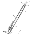
- FIG. 1 is a longitudinal sectional view showing a thermochromic writing instrument according to one embodiment of the present invention.
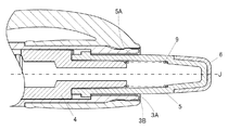
- FIG. 2 is a longitudinal sectional view showing a state where the writing tip portion in FIG. 1 protrudes.
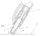
- FIG. 3 is a diagram illustrating an example of a state in which the friction portion in FIG. 1 is used.
- FIG. 4 is an enlarged cross-sectional view of a main part, partly omitted from FIG.
- FIG. 5 is an enlarged cross-sectional view of a main part, partly omitted from FIG.
- FIG. 6 is an enlarged cross-sectional view of a main part, partly omitted from FIG.
- thermochromic writing instrument 1 a writing body 14 made of a ballpoint pen refill accommodated in a shaft cylinder body is slid toward the rear end direction of the shaft cylinder body by an elastic body 7 made of a coil spring. It is energized and accommodated freely.
- the shaft tube main body is composed of a shaft tube (front shaft) 2 and a shaft tube (rear shaft) 3, and the shaft tube (front shaft) 2 and the shaft tube (rear shaft) 3 are detachably screwed to attach the shaft tube body.
- the head cylinder (rear shaft) 3 is provided with a crown 8 having a clip.
- the projectile 7 is directly received by the inner wall of the shaft cylinder (front shaft) 2, and the other end (rear end) is directly applied to the tip holder 12 of the writing body 10. In contact therewith, the writing body 10 is urged toward the rear end of the axial tube body.
- a knock body 5 is disposed at the rear end portion of the shaft tube (rear shaft) 3 so as to protrude rearward from the rear end 3A of the shaft tube (rear shaft) 3.
- the knock body 5 is integrally provided with a plurality of serrated cam portions (not shown) at the front end so as to move the rotating cam 4 forward and to induce rotation at the front end.
- a friction part 6 is attached to the rear end part (corner part of the outer peripheral surface) of the knock body 5.
- an elastic material having rubber-like elasticity is used.
- elastic materials include rubbers having rubber-like elasticity, such as silicone rubber, fluorine rubber, chloroprene rubber, nitrile rubber, polyester rubber, ethylene propylene diene rubber (EPDM), styrene elastomer, ester elastomer, and olefin elastomer.
- an elastic body such as an elastomer, which can be appropriately selected and used.
- Shore A hardness 40 or more and 100 or less are preferable, and Shore A hardness 60 or more and 80 or less are more preferable.
- the elastic material constituting the friction part is not a highly wearable elastic material (for example, an eraser) but a low wear elastic material that hardly generates wear debris during friction.
- the friction portion 6 may be integrated with or separate from the knock body as long as it is provided at least at the corner of the outer peripheral surface of the rear end of the knock body. Specifically, it is provided by fitting, press-fitting, screwing, bonding, and fusing to the knock body, the knock body and the friction part are integrally formed by two-color molding, or the knock body itself is constituted by a soft member. There may be. Further, the color of the friction part is not particularly limited, but it is preferable to use colorless and transparent, colorless and translucent color, white, etc., because it leads to cost reduction such as common use of parts.
- the knock body 5 is provided so as to be tiltable in the radial direction with respect to the axial center J of the shaft cylinder, and the rear end 3A of the shaft cylinder (rear shaft) 3 when the writing tip 13 of the writing body 10 is in the protruding state and the immersed state. In the direction, it is urged rearward by the elastic member 9.
- the intruding mechanism presses the knock body 5 in the direction of the distal end opening 2 a of the shaft cylinder (front shaft) 2, so that a cam portion (not shown) provided at the front end portion of the knock body 5 and the rotating cam 4
- a conventionally known rotary cam camshaft mechanism is actuated so that the writing tip portion 13 made of a ballpoint pen tip can be projected and retracted from the tip opening 2 a of the shaft cylinder (front shaft) 2.
- the writing body 10 has a ball holding chamber, an ink circulation opening in the center of the ball holding chamber, and an ink circulation groove that extends radially to the ink circulation opening and does not reach the chip rear opening. Furthermore, a ⁇ 0.5mm tungsten carbide ball is placed on the bottom wall of the ball holding chamber, and the tip of the tip is crimped inward so that a part of the ball rotates so as to protrude from the tip of the tip. A writing tip 13 made of a ballpoint pen tip that is freely held is formed. The writing tip portion 13 is attached to the tip portion of the ink containing cylinder 11 via the chip holder 12. Further, a tail plug is attached to the rear end portion of the ink containing cylinder 11. In addition, a spring (not shown) that constantly presses the ball is disposed behind the ball.
- thermochromic ink is stored.
- reversible thermochromic ink is preferable.
- Reversible thermochromic ink is a heat-erasable type that decolorizes by heating from a colored state, a color memory-holding type that reversibly stores a colored state or a decolored state in a specific temperature range, or heated from a decolored state
- Various types such as a heat-coloring type that develops color by the coloration and returns to the decolored state by cooling from the colored state can be used alone or in combination.
- the coloring materials contained in the reversible thermochromic ink are conventionally known (a) electron-donating color-forming organic compounds, (b) electron-accepting compounds, and (c) the color reaction of the both.
- a reversible thermochromic microcapsule pigment in which a reversible thermochromic composition containing at least three essential components of a reaction medium for determining the occurrence temperature is encapsulated in a microcapsule is preferably used.
- the ink containing cylinder 11 contains a reversibly thermochromic microcapsule pigment having an average particle diameter (D50) on a volume basis by laser diffraction of 0.5 ⁇ m, and is 1 rpm in an EM type rotational viscometer.
- a thermochromic ink having an ink viscosity of 1020 mPa ⁇ s (25 ° C.) at 100 rpm, an ink viscosity of 84 mPa ⁇ s (25 ° C.) at 100 rpm, and a shear thinning index of 0.48;
- a grease-like ink follower is stored directly.
- the ball moves to the bottom wall side by the rotation of the ball of the writing tip 13 and the writing pressure, a gap is formed between the inner wall of the tip of the tip and the ball, and ink is discharged to write. can do.
- the friction portion 6 provided at the corner of the rear end portion of the knock body 5 is pressed against and rubbed with the handwriting written on the paper surface H such as a notebook.
- the handwriting of the thermochromic ink can be thermally decolored by the heat generated.
- the knock body 5 tilts in the radial direction, and the outer surface 5A of the knock body 5 and the inner surface 3B of the shaft cylinder (rear shaft) 3 facing this are formed.
- the movement of the knock cylinder 5 to the front end opening 2a side of the shaft cylinder (front shaft) 2 is suppressed.
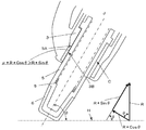
- FIGS. 7 and 8 a mechanism for increasing the frictional force between the outer surface 5A of the knock body 5 and the inner surface 3B of the shaft cylinder (rear shaft) 3, and the knock body 5 is the shaft cylinder.
- FIG. 7 schematically shows a state in which the outer surface 5A of the knock body 5 and the inner surface 3B of the shaft cylinder (rear shaft) 3 are in contact with each other when the friction operation is performed with the friction portion in contact with the paper surface.
- FIG. FIG. 8 is a diagram schematically showing means for increasing the coefficient of friction between the outer side surface 5A of the knock body 5 and the inner side surface 3B of the shaft cylinder (rear shaft) 3 facing the knock body 5.
- FIG. 7 shows a frictional force between the outer surface 5A of the knock body 5 and the inner surface 3B of the shaft cylinder (rear shaft) 3 and the knock body 5 at the front end of the shaft cylinder (front shaft) 2 in the state shown in FIG.
- It is a schematic diagram which shows the relationship of the force moved to the opening part 2a side.
- the angle formed by the axis J of the thermochromic writing instrument 1 and the paper surface H is ⁇
- the reaction force received by the thermochromic writing instrument 1 from the paper surface H is R
- the friction coefficient between the three inner side surfaces 3B is ⁇ .
- the force for moving the knock body 5 to the front end opening 2a side of the shaft cylinder (front shaft) 2 can be expressed by R * Sin ⁇
- the frictional force between the inner side surfaces 3B can be expressed by ⁇ * R * Cos ⁇ .
- the angle ⁇ formed by the axis J of the thermochromic writing instrument 1 and the paper surface H is usually said to be 70 to 80 degrees.
- the coefficient of friction of the resin due to Coulomb force is usually said to be around 1 at the maximum.
- the movement of the tube (front shaft) 2 toward the front end opening 2a cannot be restricted.
- the present inventors provide an uneven surface on at least one of the outer side surface 5A of the knock body 5 and the inner side surface 3B of the opposite shaft cylinder (rear shaft) 3 to thereby provide the outer surface 5A and the shaft cylinder of the knock body 5. It has been found that the coefficient of friction ⁇ between the inner surface 3B of the (rear shaft) 3 can be remarkably increased.
- 8A shows a case where the outer surface 5A of the knock body 5 is provided with an uneven surface
- FIG. 8B shows an uneven surface provided on the inner surface 3B of the shaft cylinder (rear shaft) 3.
- FIG. 8C shows a case where uneven surfaces are provided on both the outer surface 5 ⁇ / b> A of the knock body 5 and the inner surface 3 ⁇ / b> B of the shaft cylinder (rear shaft) 3.
- At least one of the region constituting the outer surface 5A of the knock body 5 and the region constituting the inner surface 3B of the shaft cylinder (rear shaft) 3 is preferably made of an elastic material having rubber-like elasticity.
- the elastic material include rubber elasticity such as silicone rubber, fluorine rubber, chloroprene rubber, nitrile rubber, polyester rubber, ethylene propylene diene rubber (EPDM), styrene elastomer, ester elastomer, and olefin elastomer.
- Examples include elastic bodies such as rubber and elastomer, which can be appropriately selected and used.
- the surface hardness is preferably from 40 to 100 Shore A hardness, more preferably from 60 to 80 Shore A hardness.
- the surface pressure between the outer side surface 5A of the knock body 5 and the inner side surface 3B of the opposed shaft cylinder (rear shaft) 3 bites into the mating surface with which the concavo-convex shape comes into contact. Spike effect occurs. More specifically, for example, a concavo-convex convex portion is subjected to a shearing force as indicated by an arrow S and is elastically deformed. At that time, the deformed convex portion tries to return to its original shape. This force of returning to the original amplifies the frictional force between the outer surface 5 ⁇ / b> A of the knock body 5 and the inner surface 3 ⁇ / b> B of the shaft cylinder (rear shaft) 3. This is generally referred to as hysteresis loss. For example, it is said that the large frictional force of an automobile tire is largely due to this hysteresis loss.
- the hardness of the surface having the surface is higher than the hardness of the surface having no uneven surface.
- the hardness of the surface having the concavo-convex surface is set to about Shore A hardness of 70 to 100, and the hardness of the surface having no concavo-convex surface is set to about 40 to 60 Shore A hardness.
- both surfaces have an uneven surface, even if the hardness of both surfaces is approximately the same, it is considered that the uneven surface meshes with each other and sufficient spike effect and hysteresis loss can be obtained.
- the uneven surface is provided on at least one of the outer side surface 5A of the knock body 5 and the inner side surface 3B of the opposed shaft cylinder (rear shaft) 3, the spike effect described above. Due to the hysteresis loss, the friction coefficient ⁇ between the outer side surface 5A of the knock body 5 and the inner side surface 3B of the shaft cylinder (rear shaft) 3 is remarkably increased. Thereby, since the forward movement of the knock body 5 with respect to the shaft cylinders 2 and 3 is prevented, the thermochromic writing instrument capable of performing a stable friction operation with a simple structure using the friction portion 6 at the rear end of the knock body 5. 1 can be provided.
- the concavo-convex shape can be more effectively bited into the mating surface. Therefore, the above-described spike effect and hysteresis loss are more effectively exhibited, and the friction coefficient ⁇ between the outer surface 5A of the knock body 5 and the inner surface 3B of the shaft cylinder (rear shaft) 3 is effectively increased. Can do.
- the surface roughness of the uneven surface of the outer surface 5A of the knock body 5 or the inner surface 3B of the shaft cylinder (rear shaft) 3 is preferably an arithmetic average roughness Ra 3.2 to 25.
- the arithmetic average roughness Ra was measured based on JIS B0601-2001 using a surface roughness measuring machine (Taylor Hobson Co., Ltd. FORM TALYSURF intra).
- FIG. 9 is a diagram schematically showing a modification of the mechanism for increasing the frictional force between the outer surface of the knock body and the inner surface of the shaft cylinder.
- the inner side surface 3B of the shaft cylinder (rear shaft) 3 has a tapered shape that spreads toward the rear end side of the writing so as to form an angle ⁇ with respect to the outer side surface 5A of the knock body 5.
- Examples of the angle ⁇ include 3 to 10 degrees.
- the front cylinder and the rear axle constitute a shaft cylinder, but the number of parts such as the front axle, the intermediate axle, the rear axle, etc., the base, the front axle, the rear axle, the head crown, etc.
- the shape of a control part and a to-be-controlled part is not specifically limited, It consists of convex shape and / or concave shape, and there is no limitation in particular, such as a protrusion part, a groove part, and a step part.
- the shape of the regulated portion is not particularly limited as long as it is a shape in which the regulating portion abuts and the movement is regulated, such as a stepped portion, a protruding portion, a recessed portion, and an opening end of the rear shaft.
- the in-and-out mechanism which consists of a rotating cam is illustrated as an in-and-out mechanism, if it is an in-and-out mechanism in which the writing front-end
- the projectile that urges the writing body in the rear end direction of the shaft tube is not limited to the coil spring, but the urging force of the projectile greatly affects the operability of the knock body.
- the urging force of the projectile is preferably set to 500 gf to 800 gf. The urging force of the projectile can be measured with a push-pull scale.
- thermochromic writing instrument of the present invention can be widely used as a retractable thermochromic writing instrument such as a retractable ballpoint pen and a retractable marker.
- Thermochromic writing instrument Shaft cylinder (front shaft) 2a Front end opening 3 Shaft cylinder (rear shaft) 3A Rear end 3B Inner side surface 4 Rotating cam 5 Knock body 5A Outer side surface 6 Friction part 7 Elastic body 8 Head crown 9 Elastic member 10 Writing body 11 Ink storage cylinder 12 Tip holder 13 Writing front end part
Landscapes
- Engineering & Computer Science (AREA)
- Mechanical Engineering (AREA)
- Mechanical Pencils And Projecting And Retracting Systems Therefor, And Multi-System Writing Instruments (AREA)
- Pens And Brushes (AREA)
Priority Applications (3)
| Application Number | Priority Date | Filing Date | Title |
|---|---|---|---|
| US16/471,840 US10787025B2 (en) | 2016-12-27 | 2017-12-15 | Thermochromic writing tool |
| EP17887338.6A EP3564041A4 (en) | 2016-12-27 | 2017-12-15 | THERMOCHROMIC WRITING TOOL |
| CN201780080475.8A CN110139763B (zh) | 2016-12-27 | 2017-12-15 | 热变色性笔具 |
Applications Claiming Priority (2)
| Application Number | Priority Date | Filing Date | Title |
|---|---|---|---|
| JP2016253411A JP6778611B2 (ja) | 2016-12-27 | 2016-12-27 | 熱変色性筆記具 |
| JP2016-253411 | 2016-12-27 |
Publications (1)
| Publication Number | Publication Date |
|---|---|
| WO2018123655A1 true WO2018123655A1 (ja) | 2018-07-05 |
Family
ID=62707299
Family Applications (1)
| Application Number | Title | Priority Date | Filing Date |
|---|---|---|---|
| PCT/JP2017/045103 Ceased WO2018123655A1 (ja) | 2016-12-27 | 2017-12-15 | 熱変色性筆記具 |
Country Status (5)
| Country | Link |
|---|---|
| US (1) | US10787025B2 (enExample) |
| EP (1) | EP3564041A4 (enExample) |
| JP (1) | JP6778611B2 (enExample) |
| CN (1) | CN110139763B (enExample) |
| WO (1) | WO2018123655A1 (enExample) |
Families Citing this family (1)
| Publication number | Priority date | Publication date | Assignee | Title |
|---|---|---|---|---|
| JP7628426B2 (ja) * | 2020-12-21 | 2025-02-10 | 株式会社パイロットコーポレーション | 出没式筆記具 |
Citations (7)
| Publication number | Priority date | Publication date | Assignee | Title |
|---|---|---|---|---|
| JPH0174194U (enExample) * | 1987-07-25 | 1989-05-19 | ||
| JPH0717585U (ja) * | 1993-08-31 | 1995-03-28 | ぺんてる株式会社 | ノック式筆記具 |
| JP2009090566A (ja) | 2007-10-10 | 2009-04-30 | Pilot Ink Co Ltd | 摩擦体 |
| JP2012223949A (ja) * | 2011-04-18 | 2012-11-15 | Pilot Ink Co Ltd | 熱変色性筆記具 |
| JP2015208952A (ja) * | 2014-04-28 | 2015-11-24 | 三菱鉛筆株式会社 | ノック式筆記具 |
| JP2016087864A (ja) * | 2014-10-31 | 2016-05-23 | 株式会社パイロットコーポレーション | 熱変色性筆記具 |
| JP2017013342A (ja) * | 2015-06-30 | 2017-01-19 | 株式会社パイロットコーポレーション | 熱変色性筆記具 |
Family Cites Families (7)
| Publication number | Priority date | Publication date | Assignee | Title |
|---|---|---|---|---|
| JPS55130887U (enExample) * | 1979-03-08 | 1980-09-16 | ||
| DE3853348T2 (de) | 1987-06-27 | 1995-12-14 | Pentel Kk | Schreibmittel. |
| JPH087585Y2 (ja) | 1989-08-01 | 1996-03-04 | オリンパス光学工業株式会社 | テープカセット |
| KR101814319B1 (ko) * | 2007-02-26 | 2018-01-02 | 파일롯트 잉크 가부시키가이샤 | 열 변색성 필기도구 및 볼펜 리필 |
| SG148122A1 (en) * | 2007-05-22 | 2008-12-31 | Pilot Ink Co Ltd | Friction body, writing instrument and writing instrument set |
| PL2532531T3 (pl) * | 2010-02-03 | 2021-08-02 | The Pilot Ink Co., Ltd | Narzędzie do pisania |
| JP6304958B2 (ja) * | 2013-07-16 | 2018-04-04 | 三菱鉛筆株式会社 | 消去部材を備えた筆記具 |
-
2016
- 2016-12-27 JP JP2016253411A patent/JP6778611B2/ja active Active
-
2017
- 2017-12-15 CN CN201780080475.8A patent/CN110139763B/zh active Active
- 2017-12-15 EP EP17887338.6A patent/EP3564041A4/en not_active Withdrawn
- 2017-12-15 WO PCT/JP2017/045103 patent/WO2018123655A1/ja not_active Ceased
- 2017-12-15 US US16/471,840 patent/US10787025B2/en active Active
Patent Citations (7)
| Publication number | Priority date | Publication date | Assignee | Title |
|---|---|---|---|---|
| JPH0174194U (enExample) * | 1987-07-25 | 1989-05-19 | ||
| JPH0717585U (ja) * | 1993-08-31 | 1995-03-28 | ぺんてる株式会社 | ノック式筆記具 |
| JP2009090566A (ja) | 2007-10-10 | 2009-04-30 | Pilot Ink Co Ltd | 摩擦体 |
| JP2012223949A (ja) * | 2011-04-18 | 2012-11-15 | Pilot Ink Co Ltd | 熱変色性筆記具 |
| JP2015208952A (ja) * | 2014-04-28 | 2015-11-24 | 三菱鉛筆株式会社 | ノック式筆記具 |
| JP2016087864A (ja) * | 2014-10-31 | 2016-05-23 | 株式会社パイロットコーポレーション | 熱変色性筆記具 |
| JP2017013342A (ja) * | 2015-06-30 | 2017-01-19 | 株式会社パイロットコーポレーション | 熱変色性筆記具 |
Non-Patent Citations (3)
| Title |
|---|
| MAKOTO WATANABE: "Friction and Wear of Polymers Against Metals", THE JAPAN INSTITUTE OF METALS AND MATERIALS JOURNAL, vol. 19, no. 1, 1980 |
| See also references of EP3564041A4 |
| SUGURU KUMAZAWA: "Master's Thesis", 2012, article "Prediction of Friction Coefficient of Tire Rubber by Multiscale Model" |
Also Published As
| Publication number | Publication date |
|---|---|
| US20200094610A1 (en) | 2020-03-26 |
| EP3564041A1 (en) | 2019-11-06 |
| CN110139763B (zh) | 2020-10-20 |
| EP3564041A4 (en) | 2019-12-18 |
| JP2018103506A (ja) | 2018-07-05 |
| CN110139763A (zh) | 2019-08-16 |
| US10787025B2 (en) | 2020-09-29 |
| JP6778611B2 (ja) | 2020-11-04 |
Similar Documents
| Publication | Publication Date | Title |
|---|---|---|
| JP5328554B2 (ja) | 熱変色性筆記具 | |
| JP5681856B2 (ja) | 熱変色性筆記具 | |
| JP2011037086A (ja) | 熱変色性筆記具 | |
| JP5653828B2 (ja) | 熱変色性筆記具 | |
| JP6192964B2 (ja) | 熱変色性筆記具 | |
| JP5681857B2 (ja) | 熱変色性筆記具 | |
| JP6845741B2 (ja) | 熱変色性筆記具 | |
| JP2014124899A (ja) | 熱変色性筆記具 | |
| JP5675015B2 (ja) | 熱変色性筆記具 | |
| JP5457263B2 (ja) | 熱変色性筆記具 | |
| JP6352586B2 (ja) | 熱変色性筆記具 | |
| JP2012232484A (ja) | 摩擦具 | |
| JP5694836B2 (ja) | 熱変色性筆記具 | |
| JP2012091473A (ja) | 熱変色性筆記具 | |
| WO2018123655A1 (ja) | 熱変色性筆記具 | |
| JP5358471B2 (ja) | 熱変色性筆記具 | |
| JP6558982B2 (ja) | 熱変色性筆記具 | |
| JP6081438B2 (ja) | 熱変色性筆記具 | |
| JP6266208B2 (ja) | 熱変色性筆記具 | |
| JP5985584B2 (ja) | 熱変色性筆記具 | |
| JP6040020B2 (ja) | 熱変色性筆記具 | |
| JP6315772B2 (ja) | 筆記具の軸筒 | |
| JP5603737B2 (ja) | 熱変色性筆記具 | |
| JP6472240B2 (ja) | 熱変色性筆記具 | |
| JP6472239B2 (ja) | 熱変色性筆記具 |
Legal Events
| Date | Code | Title | Description |
|---|---|---|---|
| 121 | Ep: the epo has been informed by wipo that ep was designated in this application |
Ref document number: 17887338 Country of ref document: EP Kind code of ref document: A1 |
|
| NENP | Non-entry into the national phase |
Ref country code: DE |
|
| ENP | Entry into the national phase |
Ref document number: 2017887338 Country of ref document: EP Effective date: 20190729 |