WO2018123401A1 - ろう付炉及びアルミニウム材のろう付方法 - Google Patents
ろう付炉及びアルミニウム材のろう付方法 Download PDFInfo
- Publication number
- WO2018123401A1 WO2018123401A1 PCT/JP2017/042646 JP2017042646W WO2018123401A1 WO 2018123401 A1 WO2018123401 A1 WO 2018123401A1 JP 2017042646 W JP2017042646 W JP 2017042646W WO 2018123401 A1 WO2018123401 A1 WO 2018123401A1
- Authority
- WO
- WIPO (PCT)
- Prior art keywords
- brazing
- inert gas
- chamber
- furnace
- moisture
- Prior art date
- Legal status (The legal status is an assumption and is not a legal conclusion. Google has not performed a legal analysis and makes no representation as to the accuracy of the status listed.)
- Ceased
Links
Images



Classifications
-
- B—PERFORMING OPERATIONS; TRANSPORTING
- B23—MACHINE TOOLS; METAL-WORKING NOT OTHERWISE PROVIDED FOR
- B23K—SOLDERING OR UNSOLDERING; WELDING; CLADDING OR PLATING BY SOLDERING OR WELDING; CUTTING BY APPLYING HEAT LOCALLY, e.g. FLAME CUTTING; WORKING BY LASER BEAM
- B23K3/00—Tools, devices or special appurtenances for soldering, e.g. brazing, or unsoldering, not specially adapted for particular methods
- B23K3/08—Auxiliary devices therefor
-
- B—PERFORMING OPERATIONS; TRANSPORTING
- B23—MACHINE TOOLS; METAL-WORKING NOT OTHERWISE PROVIDED FOR
- B23K—SOLDERING OR UNSOLDERING; WELDING; CLADDING OR PLATING BY SOLDERING OR WELDING; CUTTING BY APPLYING HEAT LOCALLY, e.g. FLAME CUTTING; WORKING BY LASER BEAM
- B23K1/00—Soldering, e.g. brazing, or unsoldering
- B23K1/008—Soldering within a furnace
-
- B—PERFORMING OPERATIONS; TRANSPORTING
- B23—MACHINE TOOLS; METAL-WORKING NOT OTHERWISE PROVIDED FOR
- B23K—SOLDERING OR UNSOLDERING; WELDING; CLADDING OR PLATING BY SOLDERING OR WELDING; CUTTING BY APPLYING HEAT LOCALLY, e.g. FLAME CUTTING; WORKING BY LASER BEAM
- B23K1/00—Soldering, e.g. brazing, or unsoldering
- B23K1/19—Soldering, e.g. brazing, or unsoldering taking account of the properties of the materials to be soldered
-
- B—PERFORMING OPERATIONS; TRANSPORTING
- B23—MACHINE TOOLS; METAL-WORKING NOT OTHERWISE PROVIDED FOR
- B23K—SOLDERING OR UNSOLDERING; WELDING; CLADDING OR PLATING BY SOLDERING OR WELDING; CUTTING BY APPLYING HEAT LOCALLY, e.g. FLAME CUTTING; WORKING BY LASER BEAM
- B23K2103/00—Materials to be soldered, welded or cut
- B23K2103/08—Non-ferrous metals or alloys
- B23K2103/10—Aluminium or alloys thereof
-
- B—PERFORMING OPERATIONS; TRANSPORTING
- B23—MACHINE TOOLS; METAL-WORKING NOT OTHERWISE PROVIDED FOR
- B23K—SOLDERING OR UNSOLDERING; WELDING; CLADDING OR PLATING BY SOLDERING OR WELDING; CUTTING BY APPLYING HEAT LOCALLY, e.g. FLAME CUTTING; WORKING BY LASER BEAM
- B23K31/00—Processes relevant to this subclass, specially adapted for particular articles or purposes, but not covered by any single one of main groups B23K1/00 - B23K28/00
- B23K31/02—Processes relevant to this subclass, specially adapted for particular articles or purposes, but not covered by any single one of main groups B23K1/00 - B23K28/00 relating to soldering or welding
-
- C—CHEMISTRY; METALLURGY
- C22—METALLURGY; FERROUS OR NON-FERROUS ALLOYS; TREATMENT OF ALLOYS OR NON-FERROUS METALS
- C22C—ALLOYS
- C22C21/00—Alloys based on aluminium
-
- F—MECHANICAL ENGINEERING; LIGHTING; HEATING; WEAPONS; BLASTING
- F27—FURNACES; KILNS; OVENS; RETORTS
- F27B—FURNACES, KILNS, OVENS OR RETORTS IN GENERAL; OPEN SINTERING OR LIKE APPARATUS
- F27B5/00—Muffle furnaces; Retort furnaces; Other furnaces in which the charge is held completely isolated
- F27B5/02—Muffle furnaces; Retort furnaces; Other furnaces in which the charge is held completely isolated of multiple-chamber type
-
- F—MECHANICAL ENGINEERING; LIGHTING; HEATING; WEAPONS; BLASTING
- F27—FURNACES; KILNS; OVENS; RETORTS
- F27B—FURNACES, KILNS, OVENS OR RETORTS IN GENERAL; OPEN SINTERING OR LIKE APPARATUS
- F27B5/00—Muffle furnaces; Retort furnaces; Other furnaces in which the charge is held completely isolated
- F27B5/04—Muffle furnaces; Retort furnaces; Other furnaces in which the charge is held completely isolated adapted for treating the charge in vacuum or special atmosphere
-
- F—MECHANICAL ENGINEERING; LIGHTING; HEATING; WEAPONS; BLASTING
- F27—FURNACES; KILNS; OVENS; RETORTS
- F27D—DETAILS OR ACCESSORIES OF FURNACES, KILNS, OVENS OR RETORTS, IN SO FAR AS THEY ARE OF KINDS OCCURRING IN MORE THAN ONE KIND OF FURNACE
- F27D7/00—Forming, maintaining or circulating atmospheres in heating chambers
- F27D7/06—Forming or maintaining special atmospheres or vacuum within heating chambers
Definitions
- the present invention relates to a brazing furnace and an aluminum material brazing method for brazing an aluminum material.
- brazing method for aluminum products the CAB (Controlled Atmosphere Brazing) method is generally used in which a fluoride-based flux is applied to the object to be treated, and the object to be treated is brazed by heating in an inert gas atmosphere. Has been.
- a brazing method for reducing the amount of flux applied to the joint or a flux on the surface of the joint is applied.
- a so-called fluxless brazing method for example, Patent Document 1
- Patent Document 1 it is empirically known that these brazing methods tend to deteriorate the brazing property when the atmospheric humidity is relatively high.
- the deterioration of brazing property also occurs when high-purity nitrogen gas obtained by vaporizing liquid nitrogen is supplied into the brazing furnace. Therefore, conventionally, it has been considered that the amount of moisture brought into the furnace from the outside of the brazing furnace is increased as the humidity of the atmosphere is increased, thereby deteriorating the brazing property.
- the moisture brought into the brazing furnace may be, for example, the outside air inevitably mixed when placing the object to be processed or a jig for fixing the object in the furnace, the moisture adsorbed on the object to be processed, etc.
- Various aspects are taken. Therefore, in order to reduce the amount of moisture brought from outside the furnace according to these aspects, preheating of the object to be processed is performed in a reduced pressure atmosphere, and brazing is performed after the water adhering to the object to be processed is vaporized.
- Patent Document 2 A brazing method has been proposed (Patent Document 2).
- At least a part of the inner wall of the brazing furnace is formed of a carbonaceous material, and oxygen in the furnace is reacted with the carbonaceous material to convert it into carbon dioxide (Patent Document 3).
- a solid electrolyte having oxygen ion conductivity There has also been proposed a technique for reducing the oxygen concentration in the brazing furnace by a method of introducing an inert gas into an oxygen pump equipped with a body and applying a voltage to the solid electrolyte body (Patent Document 4).
- the present invention has been made in view of such a background, and a brazing furnace capable of easily stabilizing the quality of brazing joint in brazing with a reduced amount of flux applied or brazing without using a flux, and It is intended to provide a brazing method.
- One aspect of the present invention is a brazing furnace used for brazing a workpiece made of an aluminum material,
- a brazing chamber provided with a heating device for heating the workpiece to a brazing temperature; an inert gas supply device for supplying an inert gas to the brazing chamber;
- the brazing furnace has a dehumidifying device that is interposed between the inert gas supply device and the brazing chamber and dehumidifies the inert gas.
- Another aspect of the present invention is an aluminum material brazing method for brazing an object made of an aluminum material in an inert gas atmosphere, Dehumidify inert gas, By supplying the dehumidified inert gas, the periphery of the object to be processed is made an inert gas atmosphere, In the brazing method for an aluminum material, the object to be treated is brazed by heating to the brazing temperature in the inert gas atmosphere.
- nitrogen gas obtained by vaporizing liquid nitrogen typically has a dew point of about ⁇ 76 ° C., and a very small amount of water of about 1 ppm by volume is contained in the nitrogen gas.
- the present inventors have caused deterioration of brazing by adding a very small amount of moisture previously contained in nitrogen gas to moisture brought in from outside the furnace. I found.
- the brazing furnace has a dehumidifying device for dehumidifying the inert gas supplied from the inert gas supply device, and is configured to supply the dehumidified inert gas into the brazing chamber. ing.
- the inert gas is not supplied directly from the inert gas supply device to the brazing chamber, but is supplied to the brazing chamber after dehumidification, so that moisture brought into the brazing chamber from outside the furnace can be reduced.
- the total amount of moisture contained in the inert gas in advance can be reduced as compared with the conventional case. Thereby, in the brazing performed without reducing the amount of flux applied or without applying the flux, it is possible to suppress the deterioration of the brazing property and form a good brazing joint.
- the influence of the atmosphere outside the brazing furnace, the storage environment of the object to be processed, etc. on the brazing property can be reduced. For this reason, by using the above brazing furnace, the amount of moisture brought into the brazing chamber is reduced even when it is difficult to strictly manage the storage environment of the object to be processed, for example, in a hot and humid area. In addition, a good brazed joint can be formed.
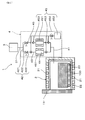
- Example 1 is a cross-sectional view showing a main part of a brazing furnace in Example 1.
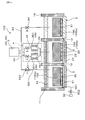
- FIG. In Example 2 it is sectional drawing which shows the principal part of the brazing furnace further provided with the preheating chamber.
- Example 3 it is sectional drawing which shows the principal part of the brazing furnace further provided with the cooling chamber.
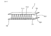
- It is a perspective view of the outer fin test body for brazing property evaluation in Experimental Example 1.
- It is a top view of the cup test body for brazing property evaluation in Experimental example 2.
- FIG. 6 is a cross-sectional view taken along line VI-VI in FIG. 5.
- any device may be used as long as the inert gas can be supplied to the brazing chamber via the dehumidifying device.
- a device for supplying an inert gas obtained by vaporizing liquid nitrogen or a device for supplying an inert gas from a cylinder filled with the inert gas can be used as the inert gas supply device.
- nitrogen when nitrogen is used as an inert gas, a device that separates nitrogen in the atmosphere by a cryogenic separation method and supplies nitrogen gas generated on the spot may be used as the inert gas supply device. Is possible.
- a non-oxidizing gas such as nitrogen gas, helium gas, or argon gas can be used.
- high-purity nitrogen gas obtained by vaporizing liquid nitrogen is usually used from the viewpoints of cost and availability. Since this nitrogen gas has a dew point of about ⁇ 76 ° C. and is already sufficiently low, the dehumidifying apparatus can be simplified by reducing the number of times of dehumidification.
- the inert gas is supplied from the inert gas supply device to the dehumidifying device. Then, the inert gas is dehumidified in the dehumidifier.
- the dehumidifying device a device appropriately selected from known dehumidifying devices according to the dew point of the inert gas and the dehumidifying performance of the device can be used.
- a dehumidifier for example, an inert gas is compressed isothermally using a compressor and the condensed moisture is removed by increasing the relative humidity, and the inert gas compressed using the compressor is applied to the water vapor permeable membrane.
- a device that selectively removes water vapor by contacting it, a device that adsorbs moisture to the moisture adsorbent by bringing an inert gas into contact with the moisture adsorbent, and the like can be used. These devices may be used alone or in combination with a plurality of devices.
- the dehumidifier is configured so that the dew point of the inert gas can be set to ⁇ 80 ° C. or lower.
- the dew point of the inert gas can be set to ⁇ 80 ° C. or lower.
- the dehumidifying device has a moisture adsorbent that comes into contact with the inert gas and adsorbs moisture in the inert gas. Since this type of dehumidifying apparatus has extremely high dehumidifying performance, it is possible to further reduce the dew point of a high purity inert gas such as nitrogen gas obtained by vaporizing liquid nitrogen. Therefore, by using a dehumidifying device provided with a moisture adsorbent, it is possible to more effectively suppress the deterioration of brazing properties.
- an adsorption tower filled with a desiccant such as silica gel, metal silicate, zeolite, or a rotor holding these desiccants can be used.
- dehumidification can be performed by passing an inert gas through the adsorption tower.
- dehumidification can be performed by bringing an inert gas into contact with the rotated rotor.
- the dehumidifier includes a plurality of gas flow paths connected in parallel to each other, a moisture adsorbent disposed on each gas flow path, and a flow path switcher that switches between supply and stop of an inert gas to each gas flow path May further be included.
- the dehumidifying performance of the moisture adsorbent may be reduced due to various causes such as the amount of adsorbed moisture approaches the saturation amount.
- the dehumidifying device equipped with the flow path switching device stops supplying the inert gas to the moisture adsorbent and continues to supply the inert gas to the other moisture adsorbent. It can be carried out. Thereby, replacement
- the dehumidifying device further includes a regenerating means for removing the moisture adsorbed on the moisture adsorbing body from the moisture adsorbing body.
- a regenerating means for removing the moisture adsorbed on the moisture adsorbing body from the moisture adsorbing body.
- the regeneration means for example, a device for desorbing moisture in the moisture adsorbent by degassing while heating the moisture adsorbent, supplying moisture to the moisture adsorbent, It is possible to use a device for desorbing moisture, a device for desorbing moisture in the moisture adsorbent by performing heating of the moisture adsorbent and introduction of the dried gas in parallel.
- the brazing furnace may have only a brazing chamber or may further include a room communicating with the brazing chamber.
- a brazing furnace includes a preheating device that preheats an object to be processed to a temperature lower than the brazing temperature, a preheating chamber connected to the brazing chamber, and a preheating pump that depressurizes the preheating chamber.
- the apparatus may further include a return pressure gas supply device for supplying an inert gas for returning the pressure in the preheating chamber after the pressure reduction.
- the brazing furnace can perform pressure reduction in the chamber and preheating of the workpiece while the workpiece is accommodated in the preheating chamber. Then, by preheating the object to be processed in a reduced pressure atmosphere, evaporation of moisture adsorbed on the object to be processed and the jig can be promoted. As a result, the amount of moisture brought into the brazing chamber can be reduced as compared with the case where preheating is not performed.
- the brazing furnace can return the preheating chamber by supplying an inert gas into the preheating chamber.
- an inert gas can avoid that the to-be-processed object and jig
- by returning the pressure of the preheating chamber using an inert gas it is possible to avoid air from being mixed into the brazing chamber when the workpiece is moved from the preheating chamber to the brazing chamber.
- the brazing furnace further provided with the preheating chamber can further reduce the amount of oxygen and moisture brought from the outside of the furnace. Therefore, by reducing the amount of flux applied or by using the above brazing furnace for brazing without applying flux, the storage environment and usage status of workpieces, jigs and brazing materials, and the environment outside the furnace It is possible to further reduce the influence of the fluctuations of brazing on the brazability. As a result, the brazing furnace can easily stabilize the quality of the brazing joint, and can more effectively suppress the deterioration of the brazing property and the occurrence of poor bonding.
- the brazing furnace is preferably configured so that the pressure in the preheating chamber can be reduced to 100 Pa or less.
- the pressure in the preheating chamber can be reduced to 100 Pa or less.
- the preheating chamber is configured so that the temperature of the object to be processed can exceed 200 ° C. In this case, evaporation of moisture adsorbed on the object to be processed can be promoted, and the amount of moisture brought into the furnace can be further reduced. Moreover, when residues such as processing oil are adhered to the object to be processed or the jig, removal of these residues can be promoted.
- the brazing furnace may further include a cooling chamber connected to the brazing chamber and a cooling gas supply device that supplies an inert gas into the cooling chamber.
- a cooling chamber connected to the brazing chamber and a cooling gas supply device that supplies an inert gas into the cooling chamber.
- the brazing furnace it is possible to braze a workpiece made of an aluminum material as follows. That is, dehumidify the inert gas, By supplying the dehumidified inert gas, the periphery of the object to be processed is made an inert gas atmosphere, Brazing can be performed by heating the workpiece to a brazing temperature in the inert gas atmosphere.
- the brazing may be performed using a workpiece to which a fluoride flux is previously applied to a portion to be brazed, or a workpiece to which a fluoride flux is not applied to a portion to be brazed. Can also be used. In the former case, the coating amount of the fluoride-based flux can be set to 2 g / m 2 or less. According to the brazing method, it is possible to reduce the amount of flux applied, or to perform good brazing in any of the brazing performed without applying the flux.
- a brazing furnace 1 configured for brazing the workpiece 100 made of an aluminum material.
- a brazing furnace 1 includes a brazing chamber 2 provided with a heating device 21 that heats the workpiece 100 to a brazing temperature, and an inert gas supply that supplies an inert gas to the brazing chamber 2.
- the apparatus 3 has a dehumidifying device 4 that is interposed between the inert gas supply device 3 and the brazing chamber 2 and dehumidifies the inert gas.
- the brazing furnace 1 of the present example is configured so that the workpiece 100 can be placed in or taken out of the furnace through an inlet / outlet provided in the brazing chamber 2.
- a front door 11 is provided at an entrance of the brazing chamber 2 so as to be openable and closable.
- the inert gas supply device 3 and the dehumidifying device 4 are disposed outside the brazing furnace 1. Further, the inert gas supply device 3 and the dehumidifying device 4, and the dehumidifying device 4 and the brazing chamber 2 are connected via gas lines 31 and 41.
- the brazing chamber 2 of the present example includes a heating device 21, a graphite muffle 22 disposed inside the heating device 21, and an endless belt type transport device 23 that transports the workpiece 100.
- the transfer device 23 is completely accommodated in the brazing chamber 2 in a state where the front door 11 is closed, and is separated from a transfer device (not shown) provided outside the brazing chamber 2. Thereby, it can prevent that the water
- the soaking area dimensions of the brazing chamber 2 are a length of 300 mm, a width of 200 mm, and a height of 200 mm.
- the inert gas supply device 3 of this example is configured to generate nitrogen gas by vaporizing liquid nitrogen.
- the dew point of the nitrogen gas generated from the inert gas supply device 3 is usually ⁇ 74 to ⁇ 78 ° C., and the oxygen concentration is usually 0.1 to 0.5 ppm.
- Nitrogen gas generated from the inert gas supply device 3 is supplied to the dehumidifying device 4 via the gas line 31.
- the dehumidifying device 4 of the present example is connected to the gas line 31, a flow path switch 42 to which nitrogen gas is supplied, and two gas flow paths 43 connected in parallel to the flow path switch 42. And a moisture adsorbent 44 disposed on each gas flow path 43 and a regenerating means 45.
- the flow path switching unit 42 can switch between supply and stop of nitrogen gas to each gas flow path 43.
- the moisture adsorber 44 is in contact with nitrogen gas and can adsorb moisture in the nitrogen gas.
- the regenerating unit 45 can remove the moisture adsorbed on the moisture adsorbing body 44 from the moisture adsorbing body 44.
- the flow path switching device 42 of this example is provided between the branching section 421 that distributes the nitrogen gas supplied from the inert gas supply device 3 to each gas flow path 43, and between the branching section 421 and each moisture adsorbing body 44.
- the switching valve 422 is provided.
- the switching valve 422 can switch between supply and stop of nitrogen gas to each moisture adsorbent 44 by switching between opening and closing.
- Each switching valve 422 can also adjust the flow rate of nitrogen gas to each moisture adsorbent 44 by adjusting the opening.
- the moisture adsorbent 44 is disposed on each gas flow path 43.
- the moisture adsorbent 44 of this example is an adsorption tower filled with zeolite.
- the dew point of the nitrogen gas that has passed through the moisture adsorbent 44 is ⁇ 80 ° C. or lower.
- the regeneration means 45 of this example includes a heater 451 for heating each moisture adsorber 44 and a regeneration pump 452 for degassing the moisture adsorber 44.
- the regeneration pump 452 is connected to the gas flow path 43 via a three-way valve 453 disposed at each of the inlet and outlet of each moisture adsorbing body 44. Further, a shutoff valve 454 that shuts off the regeneration pump 452 and the three-way valve 453 is interposed between the regeneration pump 452 and the three-way valve 453.
- the heater 451 is used to heat the moisture adsorbent 44, but the moisture adsorbent 44 is heated using another heating device such as a microwave heating device instead of the heater 451. Is also possible.
- the switching valve 422 connected to the water adsorbent 44 is closed, and then the closed flow including the water adsorbent 44, the two three-way valves 453, and the regeneration pump 452. Configure the road.
- the moisture adsorber 44 is degassed by the regeneration pump 452 while the heater 451 warms the moisture adsorbent 44.
- the adsorbed water is desorbed from the heated water adsorbent 44.
- the moisture adsorbent 44 can be regenerated and the dehumidifying performance can be recovered.
- Nitrogen gas that has passed through the moisture adsorbent 44 and has a dew point of ⁇ 80 ° C. or lower is supplied into the brazing chamber 2 via the gas line 41.
- the dew point of this nitrogen gas is usually ⁇ 80 to ⁇ 84 ° C., and the oxygen concentration is usually 0.1 to 0.5 ppm.
- the brazing furnace 1 of this example is configured so that the dehumidified nitrogen gas of 5 m 3 / h is constantly supplied into the brazing chamber 2 and the inside of the brazing chamber 2 can be replaced with nitrogen gas. . After the brazing chamber 2 is filled with nitrogen gas, excess nitrogen gas is discharged from a gas escape port (not shown) provided near the front door 11.
- the brazing furnace 1 has a dehumidifying device 4 that dehumidifies the nitrogen gas supplied from the inert gas supply device 3 so that the dehumidified nitrogen gas can be supplied into the brazing chamber 2. It is configured.
- the nitrogen gas generated from the inert gas supply device 3 is not supplied to the brazing chamber 2 as it is, but is further dehumidified and then supplied to the brazing chamber 2 to braze from the outside of the furnace.
- the total amount of moisture brought into the chamber 2 and moisture previously contained in the nitrogen gas can be reduced as compared with the conventional case. Thereby, in the brazing performed without reducing the amount of flux applied or without applying the flux, it is possible to suppress the deterioration of the brazing property and form a good brazing joint.
- the influence of the atmosphere outside the brazing furnace 1, the storage environment of the workpiece 100, etc. on the brazing property can be reduced. Therefore, the use of the brazing furnace 1 brings moisture into the brazing chamber 2 even when, for example, it is difficult to strictly manage the storage environment of the workpiece 100 in a hot and humid area or time. The amount can be reduced and a good brazed joint can be formed.
- the inert gas supply device 3 is configured to generate high purity nitrogen gas by vaporizing liquid nitrogen. Therefore, the dehumidifying device 4 can be simplified by reducing the number of times of dehumidification.
- the dehumidifying device 4 has a moisture adsorbing body 44 that comes into contact with nitrogen gas and adsorbs moisture in the nitrogen gas. Thereby, the dew point of the high purity nitrogen gas generated from the inert gas supply device 3 can be further reduced, and an extremely low dew point of ⁇ 80 ° C. or less can be easily realized. As a result, it is possible to more effectively suppress the deterioration of brazing in brazing performed without reducing the amount of flux applied or without applying flux.
- the dehumidifier 4 includes two gas flow paths 43 connected in parallel to each other, a moisture adsorbent 44 disposed on each gas flow path 43, and supply and stop of nitrogen gas to each gas flow path 43. And a flow path switching unit 42 for switching between. Therefore, when the dehumidifying performance of any one of the water adsorbents 44 decreases, the supply of the nitrogen gas to the water adsorbents 44 is stopped and the supply of the nitrogen gas to the other water adsorbents 44 is continued. Can be done. Thereby, replacement
- the dehumidifying device 4 further includes a regeneration unit 45 that removes moisture adsorbed on the moisture adsorbing body 44 from the moisture adsorbing body 44.
- a regeneration unit 45 that removes moisture adsorbed on the moisture adsorbing body 44 from the moisture adsorbing body 44.
- Example 2 This example is an example of a two-chamber brazing furnace 102 including a brazing chamber 2 and a preheating chamber 5 connected to the brazing chamber 2.
- the same reference numerals as those used in the above-described embodiments represent the same constituent elements as those in the above-described embodiments unless otherwise specified.
- the brazing furnace 102 of this example includes a brazing chamber 2 and a preheating device 51 that preheats the workpiece 100 to a temperature lower than the brazing temperature, and continues to the brazing chamber 2.
- the brazing furnace 102 is configured so that the workpiece 100 can be placed in or taken out of the furnace through an inlet / outlet provided in the preheating chamber 5.
- a front door 11 is provided at the entrance of the preheating chamber 5 so as to be openable and closable.
- the preheating chamber 5 is connected to the brazing chamber 2, and an intermediate door 12 is provided between the preheating chamber 5 and the brazing chamber 2 so as to be opened and closed.
- the preheating pump 52 is disposed outside the brazing furnace 102 and is connected to the preheating chamber 5 via an exhaust line 521.
- the exhaust line 521 is provided with an exhaust valve 522 that blocks between the preheating pump 52 and the preheating chamber 5.
- the preheating pump 52 of this example is an oil rotary pump with a mechanical booster pump.
- the inert gas supply device 3 is also used as the return pressure gas supply device 53.
- the inert gas supply device 3 is also connected to the preheating chamber 5 through the return pressure gas line 531.
- nitrogen gas obtained by vaporizing liquid nitrogen is supplied into the preheating chamber 5.
- the return pressure gas line 531 is provided with a return pressure valve 532 that blocks between the inert gas supply device 3 and the preheating chamber 5.
- the inert gas supply device 3 is configured to always supply 5 m 3 / h nitrogen gas into the preheating chamber 5.
- the surplus nitrogen gas supplied into the preheating chamber 5 is discharged from a gas escape port (not shown) provided near the front door 11.
- the preheating chamber 5 of this example includes a preheating device 51, a stainless steel muffle 54 disposed inside the preheating device 51, and an endless belt type conveying device 55 that conveys the workpiece 100. .
- the soaking area dimensions of the preheating chamber 5 are a length of 300 mm, a width of 200 mm, and a height of 200 mm.
- the preheating chamber 5 is configured such that the pressure in the room can be reduced to 0.4 Pa or less by operating the preheating pump 52 with the front door 11 and the intermediate door 12 closed.
- the indoor pressure can be measured with a Pirani gauge (not shown).
- Others are the same as in the first embodiment.
- the dehumidifying device 4 of this example includes a regeneration pump 452, a three-way valve 453, and a shut-off valve 454 as in the first embodiment. However, these descriptions are omitted in FIG.
- the brazing furnace 102 of this example can be used as follows, for example. First, the front door 11 is opened and the workpiece 100 made of an aluminum material is placed in the preheating chamber 5. Next, the front door 11 and the intermediate door 12 are closed. In this state, the preheating pump 52 is operated to evacuate the preheating chamber 5, and the preheating device 51 is operated to preheat the workpiece 100 (100a).
- the timing for starting the exhaust and the timing for starting the preheating of the workpiece 100a may be the same, or one of them may be started first. From the viewpoint of avoiding unnecessary oxidation of the workpiece 100a, it is preferable to start exhausting before starting the preheating.
- the ultimate temperature in the preheating can be, for example, 200 ° C. or higher.
- Preheating is completed when the pressure in the preheating chamber 5 reaches 100 Pa or less and the temperature of the workpiece 100a reaches a desired temperature.
- the exhaust valve 522 is closed, and then the preheating pump 52 and the preheating device 51 are stopped. Thereafter, the return pressure valve 532 is opened, and the inside of the preheating chamber 5 is returned to atmospheric pressure with nitrogen gas. Thereby, the circumference
- the return pressure valve 532 is closed, and then the intermediate door 12 is opened. Thereafter, the workpiece 100 is conveyed into the brazing chamber 2 and the intermediate door 12 is closed. Since the dehumidified nitrogen gas is constantly supplied into the brazing chamber 2, a nitrogen gas atmosphere is maintained around the workpiece 100 during the transfer of the workpiece 100.
- the workpiece 100 (100b) disposed in the brazing chamber 2 is heated by the heating device 21 and brazed.
- the intermediate door 12 is opened and the workpiece 100 is conveyed to the preheating chamber 5. Since the nitrogen gas atmosphere is maintained in the preheating chamber 5, the brazed workpiece 100 can be cooled in the nitrogen gas atmosphere. After this cooling, the front door 11 is opened and the workpiece 100 is taken out of the furnace. As described above, the workpiece 100 can be brazed.
- the brazing furnace 102 of this example is configured to be able to perform preheating in a reduced pressure atmosphere, return pressure by supplying nitrogen gas, and brazing in an atmosphere of dehumidified nitrogen gas. Therefore, when performing brazing with a reduced amount of flux applied or brazing without using flux, as described above, the storage environment and usage status of the workpiece 100, the jig and the brazing material, the environment outside the furnace, It is possible to further reduce the influence of fluctuations and the like on the brazability. As a result, it is possible to more effectively suppress the deterioration of the brazing property and stably form a good brazing joint.
- the brazing furnace 102 can be suitably used even in high temperature and high humidity areas and seasons, for example, because the influence of the storage status of the workpiece 100 etc. on the brazing property can be further reduced. Furthermore, the brazing furnace 102 can form a good brazing joint even in a work environment where strict management such as the storage environment of the workpiece 100 and the jig is difficult. In addition, the brazing furnace 102 of the present example can achieve the same effects as those of the first embodiment.
- Example 3 This example is an example of a three-chamber brazing furnace 103 including a preheating chamber 5, a brazing chamber 2, and a cooling chamber 6. As shown in FIG. 3, in the brazing furnace 103 of this example, the preheating chamber 5, the brazing chamber 2, and the cooling chamber 6 are connected in this order.
- the preheating chamber 5 is provided with an inlet for placing the workpiece 100 into the furnace.
- a front door 11 is provided at the entrance so as to be openable and closable.
- An intermediate door 12 is provided between the preheating chamber 5 and the brazing chamber 2 so as to be openable and closable, and a rear door 13 is provided between the brazing chamber 2 and the cooling chamber 6 so as to be openable and closable. .
- the cooling chamber 6 has an endless belt-type transport device 61 that transports the workpiece 100. Further, the cooling chamber 6 is provided with an outlet for taking out the workpiece 100 out of the furnace. At the outlet, an outlet door 14 for suppressing air contamination from the outside of the brazing furnace 103 is provided to be openable and closable. Instead of the exit door 14, a metal curtain or the like may be installed.
- a cooling gas supply device 62 disposed outside the furnace is connected to the cooling chamber 6 via a cooling gas line 63.
- the inert gas supply device 3 is also used as the cooling gas supply device 62.
- the inert gas supply device 3 is also connected to the cooling chamber 6 via the cooling gas line 63.
- the cooling gas line 63 is provided with a cooling gas valve 64 that blocks between the inert gas supply device 3 and the cooling chamber 6.
- the inert gas supply device 3 is configured to always supply 5 m 3 / h nitrogen gas into the cooling chamber 6.
- the surplus nitrogen gas supplied into the cooling chamber 6 is discharged from a gas escape port (not shown) provided in the vicinity of the outlet door 14.
- the brazing furnace 103 of this example is configured so that the workpiece 100 can be placed in the furnace through an inlet provided in the preheating chamber 5.
- the workpiece 100 (100a) disposed in the preheating chamber 5 is transported to the brazing chamber 2 after being preheated.
- the workpiece 100 (100b) for which brazing has been completed in the brazing chamber 2 is conveyed to the cooling chamber 6.
- the workpiece 100 (100c) cooled in the nitrogen gas atmosphere in the cooling chamber 6 is taken out of the furnace from the outlet of the cooling chamber 6.
- Others are the same as in the second embodiment.
- the dehumidifying device 4 of this example includes a regeneration pump 452, a three-way valve 453, and a shutoff valve 454 as in the first embodiment. However, these descriptions are omitted in FIG.
- the brazing furnace 103 of this example further includes the cooling chamber 6 connected to the brazing furnace 103 and the cooling gas supply device 62 for supplying nitrogen gas into the cooling chamber 6.
- the brazing furnace 103 can suppress unnecessary oxidation of the workpiece 100 by cooling the workpiece 100 in the cooling chamber 6 in a nitrogen gas atmosphere.
- the cooling chamber 6 is filled with nitrogen gas, it is possible to suppress air from entering the brazing chamber 2 from the cooling chamber 6.
- the brazing furnace 103 of this example can achieve the same effects as those of the second embodiment.
- the cooling chamber 6 may be further configured to be able to exhaust and return to the room. In this case, air can be reliably prevented from being mixed into the cooling chamber 6 by exhausting the interior of the cooling chamber 6 and then restoring the pressure with nitrogen gas.
- a configuration capable of realizing such a function for example, a configuration in which an exhaust line of a preheating pump is connected to the cooling chamber 6 similarly to the preheating chamber 5 can be considered.
- the inert gas supply device 3 is also used as the return pressure gas supply device 53 and the cooling gas supply device 62.
- the return pressure gas supply device 53 and the cooling gas supply device 62 they are independent of each other.
- a gas supply device may be provided.
- Example 1 In this example, brazing is performed by variously changing the dew point of the inert gas supplied to the brazing chamber 2.
- two types of aluminum materials (test materials A1 and A2) having chemical components and a laminated structure shown in Table 1 were prepared. These test materials are single-sided brazing sheets having a thickness of 0.6 mm in which a brazing material is clad-bonded to one side of a core material.
- an outer fin test body 7 simulating a joint portion between an outer fin and a refrigerant flow path in a parallel flow type heat exchanger was produced and brazed.
- the test body 7 of this example includes a corrugated fin 71 and two flat plates 72 that sandwich the corrugated fin 71.
- the corrugated fins 71 are made of JIS A3003 alloy.
- the flat plate 72 is made of a test material, and the brazing material 721 of the flat plate 72 is in contact with the top 711 of the corrugated fin 71.
- the length of the corrugated fin 71 is 50 mm.
- the length of the flat plate 72 is 60 mm, the width is 25 mm, and the distance between the flat plates is 10 mm.
- test body 7 was assembled as follows. First, the A3003 alloy plate was cut to a predetermined size, and then corrugated to produce corrugated fins 71. Separately from the production of the corrugated fins 71, the test material was cut into the above dimensions to produce a flat plate 72. These parts were degreased with acetone.
- a fluoride-based flux was applied on the brazing material 721 in the application amount shown in Table 2.
- the amount of flux applied was calculated as follows. After measuring the mass (g) of the flat plate 72 in advance before applying the flux, the flux was applied and further dried. The mass (g) of the flat plate 72 before flux application was subtracted from the mass (g) of the flat plate 72 after drying the flux, and the total amount (g) of the applied flux was calculated. By dividing this total amount (g) by the flux application area (cm 2 ), that is, the area of the brazing material 721, the flux application amount (g / cm 2 ) was calculated.
- the corrugated fins 71 and the flat plate 72 were sequentially placed on the flat plate 72, and the test body 7 shown in FIG. 4 was assembled.
- the specimen 7 was sandwiched and fixed in the stacking direction by a jig (not shown).
- the test body 7 was brazed by using the brazing furnace 102 (see FIG. 2) shown in Example 2 and performing preheating and brazing additional heat sequentially.
- Table 2 in Experiment Nos. 1, 3, and 4, the test body 7 was placed in the preheating chamber 5 and preheated under conditions of heating to 200 ° C. in a normal pressure nitrogen gas atmosphere. .
- the specimen 7 was placed in the preheating chamber 5 and preheating was performed under the condition of heating to 300 ° C. in a reduced pressure atmosphere reduced to 10 Pa.
- the specimen 7 was transferred into the brazing chamber 2 and heated to 600 ° C. at a rate of temperature increase of about 13 ° C./min to perform brazing addition heat.
- nitrogen gas dehumidified using the dehumidifier 4 so that the dew point was ⁇ 80 ° C. or lower was supplied into the brazing furnace 1.
- the dew point of nitrogen gas generated from the inert gas supply device 3 was adjusted to ⁇ 55 ° C. and then supplied to the brazing chamber 2 without dehumidification.
- test body 7 was transferred to the preheating chamber 5 and the test body 7 was cooled to 450 ° C. in the preheating chamber 5. Thereafter, the test body 7 was taken out of the furnace.
- the corrugated fins 71 were peeled off from the specimen 7 after brazing, and the joining rate was calculated by the following method based on the traces of the fillets present on the flat plate 72. First, about the trace of each fillet, the length in the width direction of the flat plate 72 was measured, and the total of these was calculated. Separately from this, the total length of fillets in the plate width direction when the flat plate 72 and the corrugated fins 71 are assumed to be completely joined was calculated. And the ratio of the former value with respect to the latter value was made into the joining rate (%). The latter value can be calculated, for example, by multiplying the width of the corrugated fin 71 by the top 711 (see FIG. 4) of the corrugated fin 71, that is, the number of portions joined to the flat plate 72.
- the symbol “A” is used when the joining rate is 95% or more
- the symbol “B” is used when the joining rate is 85% or more and less than 95%
- the value is 60% or more and less than 85%.
- the symbol “C” was indicated
- the symbol “D” was indicated.
- the cases of symbols A to B having a joining rate of 85% or more were determined to be acceptable because the brazing was good.
- the cases of symbols C to D having a joining rate of less than 85% were determined to be unacceptable due to the risk of brazing failure.
- the dew point of the nitrogen gas supplied into the brazing chamber 2 may be set to ⁇ 80 ° C. or lower. could not.
- Table 2 the brazability deteriorated.
- Experiment No. 4 even when nitrogen gas obtained by vaporizing liquid nitrogen was supplied as it was, a good brazing joint could not be formed.
- Example 2 In this example, the cup specimen 8 shown in FIGS. 5 and 6 is used to evaluate the brazing property when the dew point of the nitrogen gas supplied to the brazing chamber 2 is variously changed.
- two types of aluminum materials (test materials B1 and B2) having chemical components and a laminated structure shown in Table 3 were prepared. These test materials are single-sided brazing sheets having a thickness of 0.4 mm in which a brazing material is clad-bonded to one side of a core material.
- the cup test body 8 (see FIGS. 5 and 6) used for brazing evaluation in this example was produced by the following method. First, the plate material collected from the test material was subjected to press working to produce a circular cup 81 shown in FIGS.
- the cup 81 had a diameter of 30 mm, and a vent hole 812 having a diameter of 5 mm was formed at the center of the bottom 811 of the cup 81.
- a flange 813 was formed on the outer peripheral edge of the cup 81.
- the cup 81 was formed so that the brazing material 814 was inside. Thereafter, the cup 81 and the corrugated fins 82 were degreased.
- the test piece 8 shown in FIGS. 5 and 6 was assembled by combining the two cups 81 and the corrugated fins 82 prepared as described above.
- the test body 8 has a hollow member 80 including two cups 81 and a corrugated fin 82 disposed inside the hollow member 80.
- the hollow member 80 has a contact portion 800 where the flanges 813 of the cup 81 are in contact with each other. Further, the corrugated fins 82 are in contact with the brazing material 814 at the bottom 811 of each cup 81.
- the symbol “C” is described when the fillet is not uniform as a whole or when a stitch occurs in a part of the fillet.
- the symbol “D” is described when a stitch occurs in the entire fillet or when the fillet is not formed.
- the above-mentioned “stitch” means a state in which the fillet is intermittently formed, that is, a state in which the fillet is interrupted due to a pinhole-like defect or the like and looks like a seam.
- the stitch does not necessarily cause the leakage of the contents from the hollow member 80, but is often treated as a defective product because the joint quality of the product is impaired as well as when the fillet is not formed.
- the aspect of the brazing furnace and the brazing method according to the present invention is not limited to the aspects of the above-described examples and experimental examples, and the configuration can be changed as appropriate without departing from the scope of the invention.
Landscapes
- Engineering & Computer Science (AREA)
- Mechanical Engineering (AREA)
- Chemical & Material Sciences (AREA)
- Materials Engineering (AREA)
- Furnace Details (AREA)
- Muffle Furnaces And Rotary Kilns (AREA)
- Electric Connection Of Electric Components To Printed Circuits (AREA)
Abstract
フラックスの塗布量を低減したろう付あるいはフラックスを使用しないろう付において、ろう付接合の品質を容易に安定させることができるろう付炉(1)及びろう付方法を提供する。ろう付炉(1)は、アルミニウム材よりなる被処理物(100)のろう付用として構成されている。ろう付炉(1)は、被処理物(100)をろう付温度に加熱する加熱装置(21)を備えたろう付室(2)と、ろう付室(2)に不活性ガスを供給する不活性ガス供給装置(3)と、不活性ガス供給装置(3)とろう付室(2)との間に介在し、不活性ガスの除湿を行う除湿装置(4)とを有している。
Description
本発明は、アルミニウム材のろう付を行うためのろう付炉及びアルミニウム材のろう付方法に関する。
例えば、熱交換器や機械用部品などのアルミニウム製品は、アルミニウム材(アルミニウム及びアルミニウム合金を含む。以下同じ。)からなる多数の部品を有している。アルミニウム製品のろう付方法としては、フッ化物系フラックスを被処理物に塗布し、不活性ガス雰囲気下において被処理物を加熱してろう付を行うCAB(Controlled Atmosphere Brazing)法が一般的に使用されている。
しかし、CAB法においては、ろう付が完了した後に、フラックスやその残渣がアルミニウムの表面に付着する。アルミニウム製品の用途によっては、これらのフラックスやその残渣が問題を起こすことがある。例えば、電子部品が搭載される熱交換器においては、その製造時にフラックス残渣により表面処理性が悪化するなどの問題が発生するおそれがある。また、例えば水冷式の熱交換器では、冷媒流路にフラックス等に起因する目詰まりが発生するなどの問題が生じるおそれもある。さらに、フラックスやその残渣を除去するためには、酸洗処理を行う必要があり、近年では、当該処理のコスト負担が問題視されている。
そこで、フラックスの使用に伴う上記の問題を抑制あるいは回避するため、従来のCAB法に替えて、接合部に塗布するフラックスの量を低減するろう付方法や、接合部の表面にフラックスを塗布せずに不活性ガス雰囲気中でろう付を行う、いわゆるフラックスレスろう付法(例えば、特許文献1)を適用することが検討されている。しかし、これらのろう付法では、大気の湿度が比較的高い時期にろう付性が悪化しやすいことが経験的に知られている。ろう付性の悪化は、液体窒素を気化させてなる高純度の窒素ガスをろう付炉内に供給した場合にも発生する。そのため、従来は、ろう付炉外から炉内に持ち込まれる水分量が大気の湿度の上昇に伴って増加することによりろう付性の悪化を招いていると考えられていた。
ろう付炉内へ持ち込まれる水分は、例えば、被処理物やこれを固定するための治具等を炉内に配置する際に不可避的に混入する外気、被処理物等に吸着した水分等の種々の態様をとっている。そこで、これらの態様による炉外からの水分の持ち込み量を低減するため、減圧雰囲気下で被処理物等の予備加熱を行い、被処理物等に付着した水分を気化させた後にろう付を行うろう付方法が提案されている(特許文献2)。
また、ろう付炉の内壁の少なくとも一部を炭素質材料で形成し、炉内の酸素を炭素質材料と反応させて二酸化炭素に変換する(特許文献3)、酸素イオン伝導性を有する固体電解質体を備えた酸素ポンプに不活性ガスを導入し、この固体電解質体に電圧を印加する(特許文献4)等の方法により、ろう付炉内の酸素濃度を低減する技術も提案されている。
しかし、フラックスの塗布量を低減し、あるいはフラックスを塗布せずにろう付を行う場合には、特許文献2~4の技術によって炉外から持ち込まれる水分の量やろう付雰囲気中の酸素濃度を低減してもなお、ろう付性が悪化することがあるのが現状である。
本発明は、かかる背景に鑑みてなされたものであり、フラックスの塗布量を低減したろう付あるいはフラックスを使用しないろう付において、ろう付接合の品質を容易に安定させることができるろう付炉及びろう付方法を提供しようとするものである。
本発明の一態様は、アルミニウム材よりなる被処理物のろう付に用いられるろう付炉であって、
上記被処理物をろう付温度に加熱する加熱装置を備えたろう付室と
上記ろう付室に不活性ガスを供給する不活性ガス供給装置と、
上記不活性ガス供給装置と上記ろう付室との間に介在し、上記不活性ガスの除湿を行う除湿装置とを有している、ろう付炉にある。
上記被処理物をろう付温度に加熱する加熱装置を備えたろう付室と
上記ろう付室に不活性ガスを供給する不活性ガス供給装置と、
上記不活性ガス供給装置と上記ろう付室との間に介在し、上記不活性ガスの除湿を行う除湿装置とを有している、ろう付炉にある。
本発明の他の態様は、アルミニウム材よりなる被処理物を不活性ガス雰囲気下においてろう付するアルミニウム材のろう付方法であって、
不活性ガスを除湿し、
上記除湿された不活性ガスを供給することにより上記被処理物の周囲を不活性ガス雰囲気にし、
該不活性ガス雰囲気下において上記被処理物をろう付温度に加熱してろう付を行う、アルミニウム材のろう付方法にある。
不活性ガスを除湿し、
上記除湿された不活性ガスを供給することにより上記被処理物の周囲を不活性ガス雰囲気にし、
該不活性ガス雰囲気下において上記被処理物をろう付温度に加熱してろう付を行う、アルミニウム材のろう付方法にある。
従来のろう付においては、上述したように、液体窒素を気化させてなる窒素ガスが不活性ガスとして使用されていた。この窒素ガスは既に十分に純度が高いため、ろう付性が悪化する原因は、炉外から混入した大気や被処理物等に吸着した水分等の、炉外からの酸素や水分の持ち込みが主な要因であると認識されていた。
ところが、液体窒素を気化させてなる窒素ガスは、典型的には-76℃程度の露点を有しており、1体積ppm程度のごく微量の水分が窒素ガス中に含まれている。本発明者らは、鋭意検討を行った結果、炉外から持ち込まれた水分に、窒素ガス中に予め含まれていたごく微量の水分が加わることにより、ろう付性の悪化を招いていることを見出した。
上記ろう付炉は、不活性ガス供給装置から供給される不活性ガスの除湿を行う除湿装置を有しており、ろう付室内に除湿された不活性ガスを供給することができるように構成されている。このように、不活性ガスを不活性ガス供給装置から直接ろう付室に供給するのではなく、除湿を行った後にろう付室に供給することにより、炉外からろう付室内に持ち込まれる水分と、不活性ガス中に予め含まれる水分との合計量を従来よりも低減することができる。これにより、フラックスの塗布量を低減し、あるいはフラックスを塗布せずに行うろう付において、ろう付性の悪化を抑制し、良好なろう付接合を形成することができる。
また、上記ろう付炉によれば、ろう付炉の外部の雰囲気や、被処理物の保管環境等がろう付性に及ぼす影響を軽減することができる。そのため、上記ろう付炉を使用することにより、例えば高温多湿な地域や時期、あるいは被処理物の保管環境を厳密に管理することが難しい場合等においてもろう付室内への水分の持ち込み量を低減し、良好なろう付接合を形成することができる。
上記ろう付炉において、不活性ガス供給装置としては、除湿装置を介して不活性ガスをろう付室に供給することができるものであれば、どのような態様の装置を使用してもよい。例えば、液体窒素等を気化させてなる不活性ガスを供給する装置や、不活性ガスが充填されたボンベから不活性ガスを供給する装置等を不活性ガス供給装置として使用することができる。また、不活性ガスとして窒素を使用する場合には、深冷分離法により大気中の窒素を分離し、その場で発生させた窒素ガスを供給する装置を不活性ガス供給装置として使用することも可能である。
不活性ガス供給装置から供給される不活性ガスとしては、窒素ガス、ヘリウムガス、アルゴンガス等の酸化性を有しないガスを使用することができる。量産設備においては、コストや供給性の観点から、通常、液体窒素を気化させてなる高純度の窒素ガスが使用される。この窒素ガスは、露点が-76℃程度であり、既に十分に低くなっているため、除湿の回数を低減して除湿装置を簡素化することができる。
不活性ガスは、不活性ガス供給装置から除湿装置に供給される。そして、除湿装置内において不活性ガスの除湿が行われる。除湿装置としては、公知の除湿装置の中から、不活性ガスの露点及び装置の除湿性能に応じて適宜選択したものを使用することができる。除湿装置としては、例えば、圧縮機を用いて不活性ガスを等温圧縮し、相対湿度を上昇させることにより凝縮した水分を除去する装置、圧縮機を用いて圧縮した不活性ガスを水蒸気透過膜に接触させることにより水蒸気を選択的に除去する装置、水分吸着体に不活性ガスを接触させることにより水分を水分吸着体に吸着させる装置等を使用することができる。これらの装置は、単独で用いてもよく、複数の装置を組み合わせて用いてもよい。
除湿装置は、不活性ガスの露点を-80℃以下にすることができるように構成されていることが好ましい。不活性ガスの露点をこのように極めて低くすることにより、炉外から持ち込まれる水分の影響を軽減することができる。その結果、フラックスの塗布量を低減し、あるいはフラックスを塗布せずに行うろう付において、ろう付性の悪化をより効果的に抑制することができる。
除湿装置は、不活性ガスと接触し、該不活性ガス中の水分を吸着する水分吸着体を有していることが好ましい。この種の除湿装置は、除湿性能が極めて高いため、液体窒素を気化させてなる窒素ガス等の、高純度の不活性ガスの露点を更に低減することができる。それ故、水分吸着体を備えた除湿装置を使用することにより、ろう付性の悪化をより効果的に抑制することができる。
水分吸着体としては、例えば、シリカゲル、メタルシリケート、ゼオライト等の乾燥剤が充填された吸着塔や、これらの乾燥剤が保持されたロータ等を使用することができる。前者の場合には、吸着塔に不活性ガスを通過させることにより除湿を行うことができる。後者の場合には、回転させたロータに不活性ガスを接触させることにより除湿を行うことができる。
除湿装置は、互いに並列に接続された複数のガス流路と、各ガス流路上に配置された水分吸着体と、各ガス流路への不活性ガスの供給と停止とを切り替える流路切替器とを更に有していてもよい。水分吸着体の除湿性能は、例えば吸着した水分量が飽和量に近づく等の種々の原因によって低下することがある。流路切替器を備えた除湿装置は、このような場合に、当該水分吸着体への不活性ガスの供給を停止した上で、他の水分吸着体への不活性ガスの供給を継続して行うことができる。これにより、不活性ガスの除湿を継続しつつ、除湿性能が低下した水分吸着体の交換等を行うことができる。その結果、上記ろう付炉のメンテナンス性をより向上させることができる。
また、除湿装置は、水分吸着体に吸着された水分を当該水分吸着体から除去する再生手段を更に有していることが好ましい。再生手段を用いて水分吸着体から水分を除去することにより、水分吸着体の除湿性能を回復させることができる。これにより、水分吸着体の交換頻度を低減し、ろう付炉のランニングコストを低減することができる。再生手段としては、例えば、水分吸着体を加温しつつ脱気することにより、水分吸着体内の水分を脱離させる装置、水分吸着体に乾燥したガスを供給することにより、水分吸着体内の水分を脱離させる装置、水分吸着体の加温と乾燥したガスの導入とを並行して行うことにより、水分吸着体内の水分を脱離させる装置等を使用することができる。
ろう付炉は、ろう付室のみを有していてもよいし、ろう付室に連通する部屋を更に備えていてもよい。例えば、ろう付炉は、被処理物をろう付温度未満の温度に予備加熱する予備加熱装置を備え、ろう付室に連なる予備加熱室と、予備加熱室の室内を減圧する予備加熱用ポンプと、上記減圧後に上記予備加熱室の室内を復圧するための不活性ガスを供給する復圧ガス供給装置とを更に有していてもよい。
この場合、上記ろう付炉は、被処理物を予備加熱室に収容した状態で、室内の減圧及び被処理物の予備加熱を行うことができる。そして、減圧雰囲気下において被処理物の予備加熱を行うことにより、被処理物及び治具に吸着した水分の蒸発を促進させることができる。その結果、予備加熱を行わない場合に比べて、ろう付室内に持ち込まれる水分の量を低減することができる。
また、上記ろう付炉は、予備加熱が完了した後、予備加熱室内に不活性ガスを供給して予備加熱室の復圧を行うことができる。これにより、予備加熱後の被処理物及び治具が大気に晒されることを回避でき、結果としてこれらへの水分の再吸着を回避することができる。更に、不活性ガスを用いて予備加熱室を復圧することにより、被処理物を予備加熱室からろう付室へ移動させる際に、ろう付室に大気が混入することを回避できる。
このように、予備加熱室を更に備えたろう付炉は、炉外からの酸素や水分の持ち込み量を更に低減することができる。それ故、フラックスの塗布量を低減し、あるいはフラックスを塗布せずに行うろう付に上記ろう付炉を用いることにより、被処理物、治具及びろう材の保管環境や使用状況、炉外環境の変動等がろう付性に及ぼす影響をより軽減することができる。その結果、上記ろう付炉は、ろう付接合の品質を容易に安定させることができ、ろう付性の悪化や接合不良の発生をより効果的に抑制することができる。
ろう付炉は、予備加熱室の室内を100Pa以下に減圧することができるように構成されていることが好ましい。予備加熱室内の圧力を100Pa以下にすることにより、予備加熱における水分等の除去をより促進することができる。その結果、予備加熱に要する時間をより短縮することができる。
予備加熱室は、被処理物の温度を200℃超にすることができるように構成されていることが好ましい。この場合には、被処理物等に吸着した水分の蒸発を促進し、炉内への水分の持ち込み量をより低減することができる。また、被処理物や治具に加工油等の残留物が付着している場合には、これらの残留物の除去を促進することもできる。
また、ろう付炉は、ろう付室に連なる冷却室と、冷却室の室内に不活性ガスを供給する冷却ガス供給装置とを更に有していてもよい。冷却室内において被処理物を不活性ガス雰囲気下で冷却することにより、被処理物の不要な酸化を抑制することができる。また、この場合には、上記冷却室が不活性ガスで満たされているため、冷却室からろう付室への大気の混入を抑制することができる。
上記ろう付炉によれば、以下のようにしてアルミニウム材からなる被処理物のろう付を行うことができる。
即ち、不活性ガスを除湿し、
上記除湿された不活性ガスを供給することにより上記被処理物の周囲を不活性ガス雰囲気にし、
該不活性ガス雰囲気下において上記被処理物をろう付温度に加熱してろう付を行うことができる。
即ち、不活性ガスを除湿し、
上記除湿された不活性ガスを供給することにより上記被処理物の周囲を不活性ガス雰囲気にし、
該不活性ガス雰囲気下において上記被処理物をろう付温度に加熱してろう付を行うことができる。
上記ろう付は、ろう付を行う部分に予めフッ化物系フラックスが塗布された被処理物を用いて行ってもよいし、ろう付を行う部分にフッ化物系フラックスが塗布されていない被処理物を用いて行うこともできる。前者の場合には、フッ化物系フラックスの塗布量を2g/m2以下とすることができる。上記ろう付方法によれば、フラックスの塗布量を低減し、あるいはフラックスを塗布せずに行うろう付のいずれにおいても良好なろう付を行うことができる。
(実施例1)
上記ろう付炉の実施例を、図を用いて説明する。本例のろう付炉1は、アルミニウム材よりなる被処理物100のろう付用として構成されている。図1に示すように、ろう付炉1は、被処理物100をろう付温度に加熱する加熱装置21を備えたろう付室2と、ろう付室2に不活性ガスを供給する不活性ガス供給装置3と、不活性ガス供給装置3とろう付室2との間に介在し、不活性ガスの除湿を行う除湿装置4とを有している。
上記ろう付炉の実施例を、図を用いて説明する。本例のろう付炉1は、アルミニウム材よりなる被処理物100のろう付用として構成されている。図1に示すように、ろう付炉1は、被処理物100をろう付温度に加熱する加熱装置21を備えたろう付室2と、ろう付室2に不活性ガスを供給する不活性ガス供給装置3と、不活性ガス供給装置3とろう付室2との間に介在し、不活性ガスの除湿を行う除湿装置4とを有している。
本例のろう付炉1は、ろう付室2に設けられた出入口を介して被処理物100を炉内へ配置し、または炉内から取り出すことができるように構成されている。ろう付室2の出入口には、前扉11が開閉可能に設けられている。不活性ガス供給装置3及び除湿装置4は、ろう付炉1の外部に配置されている。また、不活性ガス供給装置3と除湿装置4との間、及び、除湿装置4とろう付室2との間は、ガスライン31、41を介して接続されている。
本例のろう付室2は、加熱装置21と、加熱装置21の内側に配置された黒鉛マッフル22と、被処理物100を搬送する無端ベルト式の搬送装置23とを有している。搬送装置23は、前扉11を閉じた状態においてろう付室2の内部に完全に収容されており、ろう付室2の外部に設けられた搬送装置(図示略)とは切り離されている。これにより、ろう付室2の外部に設けられた搬送装置に付着した水分や油分等が炉内へ持ち込まれることを防止できる。ろう付室2の均熱域寸法は、長さ300mm、幅200mm、高さ200mmである。
本例の不活性ガス供給装置3は、液体窒素を気化させることにより窒素ガスを発生するように構成されている。不活性ガス供給装置3から発生した窒素ガスの露点は通常-74~-78℃であり、酸素濃度は通常0.1~0.5ppmである。不活性ガス供給装置3から発生した窒素ガスは、ガスライン31を介して除湿装置4に供給される。
本例の除湿装置4は、ガスライン31に接続され、窒素ガスが供給される流路切替器42と、流路切替器42に対して互いに並列に接続された2本のガス流路43と、各ガス流路43上に配置された水分吸着体44と、再生手段45とを有している。流路切替器42は、各ガス流路43への窒素ガスの供給と停止とを切り替えることができる。水分吸着体44は、窒素ガスと接触し、該窒素ガス中の水分を吸着することができる。再生手段45は、水分吸着体44に吸着された水分を当該水分吸着体44から除去することができる。
本例の流路切替器42は、不活性ガス供給装置3から供給された窒素ガスを各ガス流路43に分配する分岐部421と、分岐部421と各水分吸着体44との間に設けられた切替バルブ422とを有している。切替バルブ422は、開閉を切り替えることにより、各水分吸着体44への窒素ガスの供給と停止とを切り替えることができる。また、各切替バルブ422は、開度を調節することにより、各水分吸着体44への窒素ガスの流量を調節することもできる。
分岐部421には、2本のガス流路43が互いに並列に接続されている。各ガス流路43上には、水分吸着体44が配置されている。本例の水分吸着体44は、具体的には、ゼオライトが充填された吸着塔である。水分吸着体44を通過した窒素ガスの露点は-80℃以下となる。
本例の再生手段45は、各水分吸着体44を加温するヒーター451と、水分吸着体44を脱気する再生用ポンプ452とを有している。再生用ポンプ452は、各水分吸着体44の入口と出口とのそれぞれに配置された三方バルブ453を介してガス流路43に接続されている。また、再生用ポンプ452と三方バルブ453との間には、再生用ポンプ452と三方バルブ453との間を遮断する遮断バルブ454が介在している。なお、本例においては、水分吸着体44の加温にヒーター451を使用したが、ヒーター451に替えて、マイクロ波加熱装置等の他の加熱装置を用いて水分吸着体44を加温することも可能である。
水分吸着体44の再生を行う場合には、まず、当該水分吸着体44に接続された切替バルブ422を閉鎖した後、水分吸着体44、2つの三方バルブ453及び再生用ポンプ452を含む閉流路を構成する。そして、ヒーター451で水分吸着体44を加温しつつ、再生用ポンプ452で水分吸着体44を脱気する。加温された水分吸着体44からは、吸着されている水分が脱離する。この水分を再生用ポンプ452で除去することにより、水分吸着体44を再生させ、除湿性能を回復させることができる。
水分吸着体44を通過し、露点が-80℃以下となった窒素ガスは、ガスライン41を介してろう付室2内に供給される。この窒素ガスの露点は通常-80~-84℃であり、酸素濃度は通常0.1~0.5ppmである。
本例のろう付炉1は、ろう付室2内に常時5m3/hの除湿された窒素ガスを供給し、ろう付室2内を窒素ガスで置換することができるように構成されている。ろう付室2内が窒素ガスにより満たされた後、余剰の窒素ガスは、前扉11付近に設けられたガス逃がし口(図示略)から排出される。
次に、本例のろう付炉1の作用効果を説明する。ろう付炉1は、不活性ガス供給装置3から供給される窒素ガスの除湿を行う除湿装置4を有しており、ろう付室2内に除湿された窒素ガスを供給することができるように構成されている。このように、不活性ガス供給装置3から発生させた窒素ガスをそのままろう付室2に供給するのではなく、更に除湿を行った後にろう付室2に供給することにより、炉外からろう付室2内に持ち込まれる水分と、窒素ガス中に予め含まれる水分との合計量を従来よりも低減することができる。これにより、フラックスの塗布量を低減し、あるいはフラックスを塗布せずに行うろう付において、ろう付性の悪化を抑制し、良好なろう付接合を形成することができる。
また、ろう付炉1によれば、ろう付炉1の外部の雰囲気や、被処理物100の保管環境等がろう付性に及ぼす影響を軽減することができる。そのため、ろう付炉1を使用することにより、例えば高温多湿な地域や時期、あるいは被処理物100の保管環境を厳密に管理することが難しい場合等においてもろう付室2内への水分の持ち込み量を低減し、良好なろう付接合を形成することができる。
また、不活性ガス供給装置3は、液体窒素を気化させることにより、高純度の窒素ガスを発生するように構成されている。そのため、除湿の回数を低減して除湿装置4を簡素化することができる。
除湿装置4は、窒素ガスと接触し、窒素ガス中の水分を吸着する水分吸着体44を有している。これにより、不活性ガス供給装置3から発生した高純度の窒素ガスの露点を更に低減し、-80℃以下という極めて低い露点を容易に実現することができる。その結果、フラックスの塗布量を低減し、あるいはフラックスを塗布せずに行うろう付において、ろう付性の悪化をより効果的に抑制することができる。
除湿装置4は、互いに並列に接続された2本のガス流路43と、各ガス流路43上に配置された水分吸着体44と、各ガス流路43への窒素ガスの供給と停止とを切り替える流路切替器42とを更に有している。そのため、いずれかの水分吸着体44の除湿性能が低下した際に、当該水分吸着体44への窒素ガスの供給を停止した上で、他の水分吸着体44への窒素ガスの供給を継続して行うことができる。これにより、窒素ガスの除湿を継続しつつ、除湿性能が低下した水分吸着体44の交換や再生等を行うことができる。その結果、ろう付炉1のメンテナンス性をより向上させることができる。
また、除湿装置4は、水分吸着体44に吸着された水分を当該水分吸着体44から除去する再生手段45を更に有している。これにより、水分吸着体44の交換頻度を低減し、ろう付炉1のランニングコストを低減することができる。
(実施例2)
本例は、ろう付室2と、ろう付室2に連なる予備加熱室5とを備えた2室型のろう付炉102の例である。なお、本実施例以降において用いる符号のうち、既出の実施例において用いた符号と同一のものは、特に説明のない限り、既出の実施例における構成要素等と同様の構成要素等を表す。
本例は、ろう付室2と、ろう付室2に連なる予備加熱室5とを備えた2室型のろう付炉102の例である。なお、本実施例以降において用いる符号のうち、既出の実施例において用いた符号と同一のものは、特に説明のない限り、既出の実施例における構成要素等と同様の構成要素等を表す。
図2に示すように、本例のろう付炉102は、ろう付室2と、被処理物100をろう付温度未満の温度に予備加熱する予備加熱装置51を備え、ろう付室2に連なる予備加熱室5と、予備加熱室5の室内を減圧する予備加熱用ポンプ52と、減圧後に予備加熱室5の室内を復圧するための不活性ガスを供給する復圧ガス供給装置53とを有している。
ろう付炉102は、予備加熱室5に設けられた出入口を介して被処理物100を炉内へ配置し、または炉内から取り出すことができるように構成されている。予備加熱室5の出入口には、前扉11が開閉可能に設けられている。また、予備加熱室5はろう付室2に連なっており、予備加熱室5とろう付室2との間には、中間扉12が開閉可能に設けられている。
予備加熱用ポンプ52は、ろう付炉102の外部に配置されており、排気ライン521を介して予備加熱室5に接続されている。排気ライン521には、予備加熱用ポンプ52と予備加熱室5との間を遮断する排気バルブ522が設けられている。なお、本例の予備加熱用ポンプ52は、メカニカルブースターポンプが付帯された油回転ポンプである。
本例においては、不活性ガス供給装置3を復圧ガス供給装置53としても利用している。具体的には、不活性ガス供給装置3は、復圧ガスライン531を介して予備加熱室5にも接続されている。これにより、予備加熱室5内に、液体窒素を気化させてなる窒素ガスが供給される。また、復圧ガスライン531には、不活性ガス供給装置3と予備加熱室5との間を遮断する復圧バルブ532が設けられている。
不活性ガス供給装置3は、予備加熱室5内に、常時5m3/hの窒素ガスを供給することができるように構成されている。なお、予備加熱室5内に供給された余剰の窒素ガスは、前扉11付近に設けられたガス逃がし口(図示略)から排出される。
本例の予備加熱室5は、予備加熱装置51と、予備加熱装置51の内側に配置されたステンレスマッフル54と、被処理物100を搬送する無端ベルト式の搬送装置55とを有している。予備加熱室5の均熱域寸法は、長さ300mm、幅200mm、高さ200mmである。
予備加熱室5は、前扉11及び中間扉12を閉鎖した状態で予備加熱用ポンプ52を作動させることにより、室内の圧力を0.4Pa以下にすることができるように構成されている。なお、室内の圧力は、ピラニゲージ(不図示)により測定することができる。その他は実施例1と同様である。なお、本例の除湿装置4は、実施例1と同様に再生用ポンプ452、三方バルブ453及び遮断バルブ454を備えているが、図2においては、便宜上、これらの記載を割愛した。
本例のろう付炉102は、例えば、以下のようにして使用することができる。まず、前扉11を開放してアルミニウム材よりなる被処理物100を予備加熱室5内に配置する。次いで、前扉11及び中間扉12を閉鎖する。この状態で、予備加熱用ポンプ52を作動させて予備加熱室5内を排気するとともに、予備加熱装置51を作動させて被処理物100(100a)の予備加熱を行う。排気を開始するタイミングと被処理物100aの予備加熱を開始するタイミングは、同時であってもよく、いずれか一方を先に開始してもよい。被処理物100aの不要な酸化を回避する観点からは、予備加熱の開始より前に排気を開始することが好ましい。
予備加熱における到達温度は、例えば、200℃以上とすることができる。予備加熱室5内の圧力が100Pa以下に到達し、かつ、被処理物100aの温度が所望の温度に到達した時点で予備加熱を完了する。予備加熱が完了した後、排気バルブ522を閉鎖し、次いで予備加熱用ポンプ52及び予備加熱装置51を停止させる。その後、復圧バルブ532を開放して予備加熱室5内を窒素ガスで大気圧まで復圧させる。これにより、被処理物100aの周囲が窒素ガス雰囲気になる。
復圧が完了した後、復圧バルブ532を閉鎖し、次いで中間扉12を開放する。その後、被処理物100をろう付室2内へ搬送し、中間扉12を閉鎖する。ろう付室2内には除湿された窒素ガスが常時供給されているため、被処理物100の搬送中、被処理物100の周囲は窒素ガス雰囲気が維持されている。
その後、ろう付室2内に配置された被処理物100(100b)を加熱装置21で加熱してろう付を行う。ろう付が完了した後、中間扉12を開けて被処理物100を予備加熱室5へ搬送する。予備加熱室5の室内は窒素ガス雰囲気が維持されているため、ろう付済みの被処理物100を窒素ガス雰囲気中で冷却することができる。この冷却の後、前扉11を開放して被処理物100を炉外へ取り出す。以上により、被処理物100のろう付を行うことができる。
本例のろう付炉102は、減圧雰囲気下における予備加熱、窒素ガスの供給による復圧及び除湿された窒素ガスの雰囲気下でのろう付を行うことができるように構成されている。それ故、フラックスの塗布量を低減したろう付あるいはフラックスを使用しないろう付を行う際に、上述したように、被処理物100、治具及びろう材の保管環境や使用状況、炉外環境の変動等がろう付性に及ぼす影響をより軽減することができる。その結果、ろう付性の悪化をより効果的に抑制し、良好なろう付接合を安定して形成することができる。
また、ろう付炉102は、被処理物100等の保管状況等がろう付性に及ぼす影響をより軽減することができるため、例えば高温多湿な地域や季節においても好適に使用することができる。更に、ろう付炉102は、被処理物100や治具の保管環境等の厳密な管理が難しい作業環境であっても良好なろう付接合を形成することができる。その他、本例のろう付炉102は、実施例1と同様の作用効果を奏することができる。
(実施例3)
本例は、予備加熱室5、ろう付室2及び冷却室6を備えた3室型のろう付炉103の例である。図3に示すように、本例のろう付炉103は、予備加熱室5、ろう付室2及び冷却室6がこの順に連なっている。予備加熱室5には、被処理物100を炉内へ配置する入口が設けられている。この入口には、前扉11が開閉可能に設けられている。予備加熱室5とろう付室2との間には中間扉12が開閉可能に設けられており、ろう付室2と冷却室6との間には後扉13が開閉可能に設けられている。
本例は、予備加熱室5、ろう付室2及び冷却室6を備えた3室型のろう付炉103の例である。図3に示すように、本例のろう付炉103は、予備加熱室5、ろう付室2及び冷却室6がこの順に連なっている。予備加熱室5には、被処理物100を炉内へ配置する入口が設けられている。この入口には、前扉11が開閉可能に設けられている。予備加熱室5とろう付室2との間には中間扉12が開閉可能に設けられており、ろう付室2と冷却室6との間には後扉13が開閉可能に設けられている。
冷却室6は、被処理物100を搬送する無端ベルト式の搬送装置61を有している。また、冷却室6には、被処理物100を炉外へ取り出すための出口が設けられている。この出口には、ろう付炉103の外部からの大気の混入を抑制するための出口扉14が開閉可能に設けられている。なお、出口扉14に替えて、メタルカーテン等を設置しても良い。
また、冷却室6には、炉外に配置された冷却ガス供給装置62が冷却ガスライン63を介して接続されている。本例においては、不活性ガス供給装置3を冷却ガス供給装置62としても利用している。具体的には、不活性ガス供給装置3は、冷却ガスライン63を介して冷却室6にも接続されている。冷却ガスライン63には、不活性ガス供給装置3と冷却室6との間を遮断する冷却ガスバルブ64が設けられている。
不活性ガス供給装置3は、冷却室6内に、常時5m3/hの窒素ガスを供給することができるように構成されている。なお、冷却室6内に供給された余剰の窒素ガスは、出口扉14付近に設けられたガス逃がし口(図示略)から排出される。
本例のろう付炉103は、予備加熱室5に設けられた入口を介して被処理物100を炉内へ配置することができるように構成されている。予備加熱室5内に配置された被処理物100(100a)は、予備加熱が施された後、ろう付室2に搬送される。ろう付室2内においてろう付が完了した被処理物100(100b)は、冷却室6に搬送される。冷却室6において窒素ガス雰囲気中で冷却された被処理物100(100c)は、冷却室6の出口から炉外に取り出される。その他は実施例2と同様である。なお、本例の除湿装置4は、実施例1と同様に再生用ポンプ452、三方バルブ453及び遮断バルブ454を備えているが、図3においては、便宜上、これらの記載を割愛した。
このように、本例のろう付炉103は、ろう付炉103に連なる冷却室6と、冷却室6の室内に窒素ガスを供給する冷却ガス供給装置62とを更に有している。ろう付炉103は、上述したように、冷却室6内において被処理物100を窒素ガス雰囲気下で冷却することにより、被処理物100の不要な酸化を抑制することができる。また、冷却室6が窒素ガスで満たされているため、冷却室6からろう付室2への大気の混入を抑制することができる。その他、本例のろう付炉103は、実施例2と同様の作用効果を奏することができる。
本例のようにろう付炉103が冷却室6を有する場合、冷却室6は、さらに、室内の排気及び復圧ができるように構成されていてもよい。この場合には、冷却室6の室内を排気し、その後窒素ガスで復圧することにより、冷却室6内への大気の混入を確実に防止することができる。かかる機能を実現可能な構成としては、例えば、予備加熱室5と同様に、予備加熱用ポンプの排気ラインを冷却室6に接続する構成等が考えられる。
また、本例においては、不活性ガス供給装置3を復圧ガス供給装置53及び冷却ガス供給装置62としても利用しているが、復圧ガス供給装置53及び冷却ガス供給装置62として、それぞれ独立したガス供給装置を設けてもよい。
(実験例1)
本例は、ろう付室2に供給する不活性ガスの露点を種々変更してろう付を行った例である。本例においては、表1に示す化学成分及び積層構造を有する2種のアルミニウム材(試験材A1、A2)を準備した。これらの試験材は、心材の片面にろう材がクラッド接合された厚み0.6mmの片面ブレージングシートである。
本例は、ろう付室2に供給する不活性ガスの露点を種々変更してろう付を行った例である。本例においては、表1に示す化学成分及び積層構造を有する2種のアルミニウム材(試験材A1、A2)を準備した。これらの試験材は、心材の片面にろう材がクラッド接合された厚み0.6mmの片面ブレージングシートである。
本例においては、パラレルフロー型熱交換器におけるアウターフィンと冷媒流路との接合部を模擬したアウターフィン試験体7を作製し、ろう付を行った。本例の試験体7は、図4に示すように、コルゲートフィン71と、このコルゲートフィン71を挟持する2枚の平板72とを有している。コルゲートフィン71はJIS A3003合金から構成されている。平板72は試験材から構成されており、平板72のろう材721がコルゲートフィン71の頂部711と当接している。コルゲートフィン71の長さは50mmである。また、平板72の長さは60mm、幅は25mmであり、平板間の間隔は10mmである。
試験体7の組み立ては、具体的には、以下のように行った。まず、A3003合金の板材を所定の寸法に切断した後、コルゲート加工を施してコルゲートフィン71を作製した。また、コルゲートフィン71の作製とは別に、試験材を上記の寸法に切断し、平板72を作製した。そして、これらの部品をアセトンにより脱脂した。
ここで、試験材A1を使用した平板72(表2、実験番号3)については、ろう材721上に、表2に示す塗布量でフッ化物系フラックスを塗布した。フラックスの塗布量は、以下のようにして算出した。フラックス塗布前に予め平板72の質量(g)を測定した後、フラックスを塗布し、更に乾燥させた。フラックスを乾燥させた後の平板72の質量(g)からフラックス塗布前の平板72の質量(g)を差し引き、塗布されたフラックスの総量(g)を算出した。この総量(g)をフラックスの塗布面積(cm2)、即ちろう材721の面積で除することにより、フラックスの塗布量(g/cm2)を算出した。
その後、平板72上にコルゲートフィン71及び平板72を順次載置し、図4に示す試験体7を組み立てた。図示しない治具によりこの試験体7を積層方向に挟持して固定した。
試験体7を治具に固定した後、実施例2に示したろう付炉102(図2参照)を用い、予備加熱及びろう付加熱を順次実施して試験体7のろう付を行った。表2に示すように、実験番号1、3、4では、試験体7を予備加熱室5内に配置し、常圧の窒素ガス雰囲気下において、200℃まで加熱する条件で予備加熱を行った。また、実験番号2では、試験体7を予備加熱室5内に配置し、10Paまで減圧した減圧雰囲気下において、300℃まで加熱する条件で予備加熱を行った。
上記の条件で予備加熱を行った後、試験体7をろう付室2内に搬送し、13℃/分程度の昇温速度で600℃まで加熱してろう付加熱を行った。このとき、表2に示すように、実験番号1、2では、除湿装置4を用いて露点が-80℃以下となるように除湿を行った窒素ガスをろう付炉1内に供給した。実験番号3では、不活性ガス供給装置3から発生させた窒素ガスの露点を-55℃に調節した後、除湿を行わずにろう付室2に供給した。実験番号4では、不活性ガス供給装置3から発生させた窒素ガスを、除湿を行わずにろう付室2に供給した。各実験における除湿前後の窒素ガスの露点及びろう付加熱時のろう付室2内の露点は、表2に示した通りであった。
ろう付が完了した後、試験体7を予備加熱室5に搬送し、予備加熱室5内において450℃まで試験体7を冷却した。その後、試験体7を炉外へ取り出した。
ろう付後の試験体7からコルゲートフィン71を剥離し、平板72上に存在するフィレットの痕跡に基づいて、以下の方法により接合率を算出した。まず、個々のフィレットの痕跡について、平板72の幅方向における長さを測定し、これらの合計を算出した。これとは別に、平板72とコルゲートフィン71とが完全に接合されたと仮定した場合の板幅方向におけるフィレットの長さの合計を算出した。そして、後者の値に対する前者の値の比率を接合率(%)とした。なお、後者の値は、例えば、コルゲートフィン71の幅と、コルゲートフィン71の頂部711(図4参照)、即ち平板72に接合される部分の数とを掛け合わせることにより算出できる。
表2の「評価結果」の欄には、接合率が95%以上である場合には記号「A」、85%以上95%未満の場合には記号「B」、60%以上85%未満の場合には記号「C」、60%未満の場合には記号「D」を記載した。アウターフィン試験体7によるろう付性評価においては、接合率が85%以上である記号A~Bの場合を、ろう付性が良好であるため合格と判定した。また、接合率が85%未満である記号C~Dの場合を、ろう付不良のおそれがあるため不合格と判定した。


表2に示したように、実験番号1、2においては、不活性ガス供給装置3から発生させた窒素ガスの除湿を行ったため、ろう付室2内に供給する窒素ガスの露点を-80℃以下とすることができた。これにより、85%以上の接合性を実現することができた。
一方、実験番号3、4においては、不活性ガス供給装置3から発生させた窒素ガスの除湿を行わなかったため、ろう付室2内に供給する窒素ガスの露点を-80℃以下とすることができなかった。その結果、表2に示したようにろう付性の悪化を招いた。特に、実験番号4に示したように、液体窒素を気化させてなる窒素ガスをそのまま供給した場合にも、良好なろう付接合を形成することはできなかった。
(実験例2)
本例では、図5及び図6に示すカップ試験体8を用い、ろう付室2に供給する窒素ガスの露点を種々変更した場合のろう付性を評価した例である。本例においては、表3に示す化学成分及び積層構造を有する2種のアルミニウム材(試験材B1、B2)を準備した。これらの試験材は、心材の片面にろう材がクラッド接合された厚み0.4mmの片面ブレージングシートである。
本例では、図5及び図6に示すカップ試験体8を用い、ろう付室2に供給する窒素ガスの露点を種々変更した場合のろう付性を評価した例である。本例においては、表3に示す化学成分及び積層構造を有する2種のアルミニウム材(試験材B1、B2)を準備した。これらの試験材は、心材の片面にろう材がクラッド接合された厚み0.4mmの片面ブレージングシートである。
本例のろう付性評価に用いたカップ試験体8(図5、図6参照)は、以下の方法により作製した。まず、試験材から採取した板材にプレス加工を施し、図5、図6に示す円形カップ81を作製した。カップ81の直径は30mmとし、カップ81の底部811における中央に、直径5mmの通気孔812を形成した。カップ81の外周縁部にはフランジ813を形成した。また、図6に示すように、カップ81は、ろう材814が内側となるように形成した。その後、カップ81及びコルゲートフィン82を脱脂した。
ここで、試験材B1を使用した天板(表4、実験番号11、14、15)については、実験例1と同様に、ろう材814上に、表4に示す塗布量でフッ化物系フラックスを塗布した。
以上により準備した2枚のカップ81及びコルゲートフィン82を組み合わせ、図5及び図6に示す試験体8を組み立てた。試験体8は、2枚のカップ81からなる中空部材80と、中空部材80の内部に配置されたコルゲートフィン82とを有している。中空部材80は、カップ81のフランジ813同士が当接した当接部800を有している。また、コルゲートフィン82は、各カップ81の底部811において、ろう材814に当接している。
図示しない治具によりこの試験体8を積層方向に挟持して固定した後、実験例1と同様の方法により、試験体8のろう付を行った。本例では、表4に示す実験番号11~13については、不活性ガス供給装置3から発生させた窒素ガスの除湿を行った。また、実験番号14~17については、不活性ガス供給装置3から発生させた窒素ガスの除湿を行わず、そのままろう付炉102内に供給した。予備加熱の条件、除湿前後における窒素ガスの露点及びろう付加熱中のろう付室2内の露点は、表4に示した通りであった。
ろう付後の試験体8を目視観察し、当接部800の外側に形成されるフィレットF(図6参照)の外観を評価した。表4の「評価結果」の欄に、フィレットが均一な形状であった場合には記号「A」を記載した。フィレットの一部がやや不均一であるが、連続したフィレットが形成された場合は記号「B」を記載した。
フィレットが全体的に不均一である、または、フィレットの一部にスティッチが発生した場合には記号「C」を記載した。フィレットの全体にスティッチが発生した、あるいは、フィレットが形成されなかった場合には記号「D」を記載した。ここで、上記の「スティッチ」とは、フィレットが断続的に形成された状態、即ち、ピンホール状の欠陥等によりフィレットが途切れ、縫い目のように見える状態をいう。スティッチは、必ずしも中空部材80からの内容物の漏れの発生を招くものではないが、フィレットが形成されない場合とともに、製品の接合品質を損ねているとして不良品扱いになることが多い。
フィレット形状評価においては、連続したフィレットが形成された記号A、Bの場合を、良好なフィレットが形成されているため合格と判定した。また、スティッチが発生した、あるいはフィレットが形成されなかった記号C、Dの場合を、ろう付不良のおそれがあるため不合格と判定した。
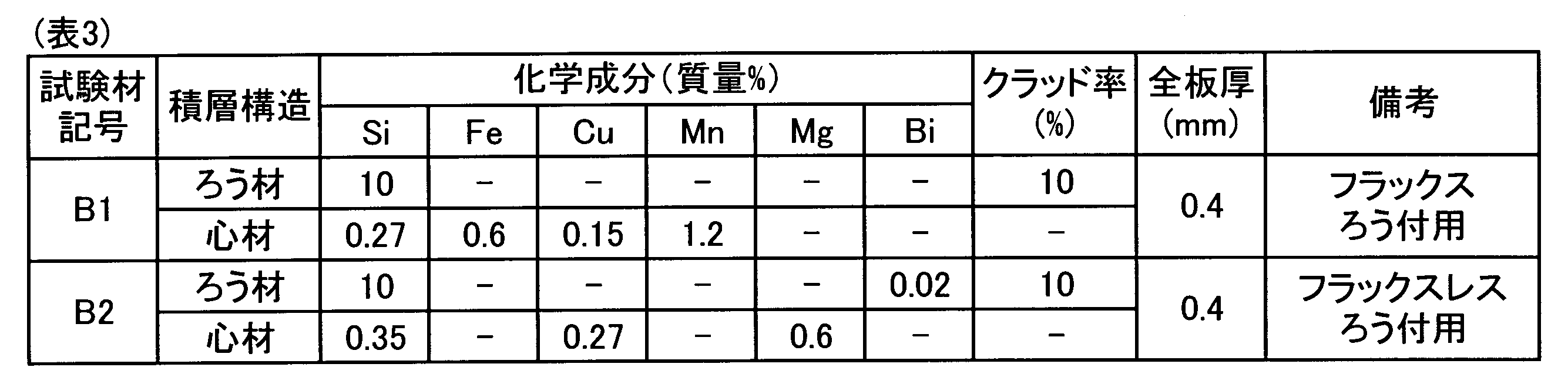
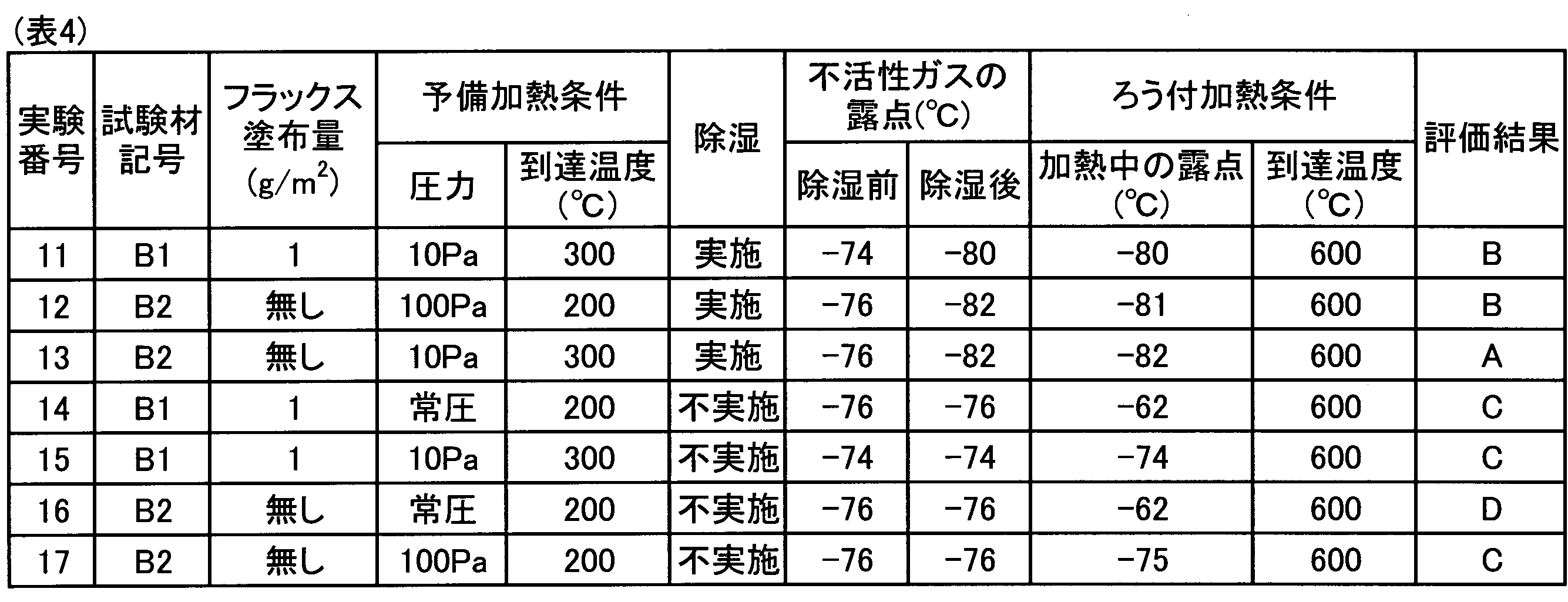
表4に示したように、実験番号11~13においては、不活性ガス供給装置3から発生させた窒素ガスの除湿を行ったため、ろう付室2内に供給する窒素ガスの露点を-80℃以下とすることができた。これにより、連続したフィレットを形成することができた。
一方、実験番号14~17においては、不活性ガス供給装置3から発生させた窒素ガスの除湿を行わなかったため、ろう付室2内に供給する窒素ガスの露点を-80℃以下とすることができなかった。その結果、表4に示したようにろう付性の悪化を招いた。
表2及び表4に示したように、除湿を行った不活性ガスをろう付室2内に供給することにより、フラックスの塗布量を低減し、またはフラックスを塗布せずに行うろう付において良好なろう付接合を形成することができた。さらに、いずれのろう付においても、アウターフィン試験体7及びカップ試験体8の両方の試験体で、良好なろう付接合を形成することができた。
これらの結果から、不活性ガス供給装置3から発生させた不活性ガスの除湿を行うことにより、ろう付性の悪化を効果的に抑制できることが理解できる。また、ろう付炉1、102、103の外部の雰囲気や、被処理物100の保管環境等がろう付性に及ぼす影響を軽減することができるため、例えば高温多湿な地域や時期、あるいは被処理物100の保管環境を厳密に管理することが難しい場合等においてもろう付室2内への水分の持ち込み量を低減し、良好なろう付接合を形成することが可能であることが理解できる。
なお、本発明に係るろう付炉及びろう付方法の態様は、上述した実施例及び実験例の態様に限定されるものではなく、その趣旨を損なわない範囲で適宜構成を変更することができる。
Claims (16)
- アルミニウム材よりなる被処理物のろう付に用いられるろう付炉であって、
上記被処理物をろう付温度に加熱する加熱装置を備えたろう付室と
上記ろう付室に不活性ガスを供給する不活性ガス供給装置と、
上記不活性ガス供給装置と上記ろう付室との間に介在し、上記不活性ガスの除湿を行う除湿装置とを有している、ろう付炉。 - 上記除湿装置は、不活性ガスと接触し、該不活性ガス中の水分を吸着する水分吸着体を有している、請求項1に記載のろう付炉。
- 上記除湿装置は、互いに並列に接続された複数のガス流路と、上記各ガス流路上に配置された水分吸着体と、上記各ガス流路への不活性ガスの供給と停止とを切り替える流路切替器とを更に有している、請求項2に記載のろう付炉。
- 上記除湿装置は、上記水分吸着体に吸着された水分を該水分吸着体から除去する再生手段を更に有している、請求項2または3に記載のろう付炉。
- 上記ろう付炉は、上記被処理物をろう付温度未満の温度に予備加熱する予備加熱装置を備え、上記ろう付室に連なる予備加熱室と、上記予備加熱室の室内を減圧する予備加熱用ポンプと、上記減圧後に上記予備加熱室の室内を復圧するための不活性ガスを供給する復圧ガス供給装置とを更に有している、請求項1~4のいずれか1項に記載のろう付炉。
- 上記ろう付炉は、上記予備加熱室の室内を100Pa以下に減圧することができるように構成されている、請求項5に記載のろう付炉。
- 上記予備加熱室は、上記被処理物の温度を200℃超にすることができるように構成されている、請求項5または6に記載のろう付炉。
- 上記ろう付炉は、上記ろう付室に連なる冷却室と、上記冷却室の室内に不活性ガスを供給する冷却ガス供給装置とを更に有している、請求項1~7のいずれか1項に記載のろう付炉。
- アルミニウム材よりなる被処理物を不活性ガス雰囲気下においてろう付するアルミニウム材のろう付方法であって、
不活性ガスを除湿し、
上記除湿された不活性ガスを供給することにより上記被処理物の周囲を不活性ガス雰囲気にし、
該不活性ガス雰囲気下において上記被処理物をろう付温度に加熱してろう付を行う、アルミニウム材のろう付方法。 - 上記除湿において、水分を吸着する水分吸着体に上記不活性ガスを接触させることにより、上記不活性ガス中の水分を除去する、請求項9に記載のアルミニウム材のろう付方法。
- 上記除湿において、露点が-80℃以下となるように上記不活性ガス中の水分を除去する、請求項9または10に記載のアルミニウム材のろう付方法。
- 上記ろう付を行う前に、上記被処理物を100Pa以下の減圧雰囲気下においてろう付温度未満の温度に予備加熱し、その後、上記ろう付を行う、請求項9~11のいずれか1項に記載のアルミニウム材のろう付方法。
- 上記被処理物のろう付を行う部分に予めフッ化物系フラックスが塗布されている、請求項9~12のいずれか1項に記載のアルミニウム材のろう付方法。
- 上記フッ化物系フラックスの塗布量は2g/m2以下である、請求項13に記載のアルミニウム材のろう付方法。
- 上記被処理物のろう付を行う部分にフラックスが塗布されていない、請求項9~12のいずれか1項に記載のアルミニウム材のろう付方法。
- 請求項1~8のいずれか1項に記載のろう付炉を用いて行う、請求項9~15のいずれか1項に記載のアルミニウム材のろう付方法。
Priority Applications (3)
| Application Number | Priority Date | Filing Date | Title |
|---|---|---|---|
| CN201780078555.XA CN110087810A (zh) | 2016-12-26 | 2017-11-28 | 钎焊炉及铝材的钎焊方法 |
| DE112017005999.2T DE112017005999B4 (de) | 2016-12-26 | 2017-11-28 | Lötofen und aluminiummaterial-lötverfahren |
| US16/472,528 US20190314916A1 (en) | 2016-12-26 | 2017-11-28 | Brazing furnace and aluminum-material brazing method |
Applications Claiming Priority (2)
| Application Number | Priority Date | Filing Date | Title |
|---|---|---|---|
| JP2016251240A JP6529482B2 (ja) | 2016-12-26 | 2016-12-26 | ろう付炉及びアルミニウム材のろう付方法 |
| JP2016-251240 | 2016-12-26 |
Publications (1)
| Publication Number | Publication Date |
|---|---|
| WO2018123401A1 true WO2018123401A1 (ja) | 2018-07-05 |
Family
ID=62707270
Family Applications (1)
| Application Number | Title | Priority Date | Filing Date |
|---|---|---|---|
| PCT/JP2017/042646 Ceased WO2018123401A1 (ja) | 2016-12-26 | 2017-11-28 | ろう付炉及びアルミニウム材のろう付方法 |
Country Status (5)
| Country | Link |
|---|---|
| US (1) | US20190314916A1 (ja) |
| JP (1) | JP6529482B2 (ja) |
| CN (1) | CN110087810A (ja) |
| DE (1) | DE112017005999B4 (ja) |
| WO (1) | WO2018123401A1 (ja) |
Families Citing this family (3)
| Publication number | Priority date | Publication date | Assignee | Title |
|---|---|---|---|---|
| JP6916715B2 (ja) | 2017-11-08 | 2021-08-11 | 株式会社Uacj | ブレージングシート及びその製造方法 |
| DE112019004536T5 (de) | 2018-09-11 | 2021-06-02 | Uacj Corporation | Verfahren zum herstellen eines hartlotblechs |
| JP7591872B2 (ja) | 2020-04-08 | 2024-11-29 | 株式会社Uacj | ブレージングシートの製造方法 |
Citations (4)
| Publication number | Priority date | Publication date | Assignee | Title |
|---|---|---|---|---|
| JPH11347336A (ja) * | 1998-06-09 | 1999-12-21 | Sanyo Denshi Kogyo Kk | 小型ガス分離装置 |
| WO2001088451A1 (en) * | 2000-05-16 | 2001-11-22 | Visteon Global Technologies, Inc. | Gettering system for brazing heat exchangers in cab furnace |
| JP2013233549A (ja) * | 2012-05-07 | 2013-11-21 | Micro Control Systems Kk | 発電の際の電力及び排ガスを利用する半田付け装置及び半田付け方法 |
| JP2016083699A (ja) * | 2014-10-28 | 2016-05-19 | 株式会社Uacj | ろう付炉及びアルミニウム材のろう付方法 |
Family Cites Families (7)
| Publication number | Priority date | Publication date | Assignee | Title |
|---|---|---|---|---|
| CA2112441C (en) * | 1992-12-29 | 2005-08-09 | Tomiyoshi Kanai | Corrosion-resistant and brazeable aluminum material and a method of producing same |
| JPH10180489A (ja) * | 1996-12-20 | 1998-07-07 | Sky Alum Co Ltd | 非酸化性ガス雰囲気無フラックスろう付け用材料の製造方法およびろう付け方法 |
| JP4592645B2 (ja) * | 2006-06-05 | 2010-12-01 | 関東冶金工業株式会社 | アルミニウム製品のろう付け用連続炉及びろう付け方法 |
| JP2011161514A (ja) * | 2010-01-14 | 2011-08-25 | Denso Corp | 銅溶接方法及び銅溶接装置 |
| JP5352001B1 (ja) * | 2012-12-21 | 2013-11-27 | 三菱アルミニウム株式会社 | アルミニウム材のろう付方法およびろう付構造体 |
| JP6144532B2 (ja) * | 2013-05-01 | 2017-06-07 | 株式会社デンソー | ブレージングシートのろう付け方法、及び熱交換器の製造方法 |
| WO2016067682A1 (ja) * | 2014-10-28 | 2016-05-06 | 株式会社Uacj | ろう付炉及びアルミニウム材のろう付方法 |
-
2016
- 2016-12-26 JP JP2016251240A patent/JP6529482B2/ja active Active
-
2017
- 2017-11-28 CN CN201780078555.XA patent/CN110087810A/zh active Pending
- 2017-11-28 US US16/472,528 patent/US20190314916A1/en not_active Abandoned
- 2017-11-28 DE DE112017005999.2T patent/DE112017005999B4/de active Active
- 2017-11-28 WO PCT/JP2017/042646 patent/WO2018123401A1/ja not_active Ceased
Patent Citations (4)
| Publication number | Priority date | Publication date | Assignee | Title |
|---|---|---|---|---|
| JPH11347336A (ja) * | 1998-06-09 | 1999-12-21 | Sanyo Denshi Kogyo Kk | 小型ガス分離装置 |
| WO2001088451A1 (en) * | 2000-05-16 | 2001-11-22 | Visteon Global Technologies, Inc. | Gettering system for brazing heat exchangers in cab furnace |
| JP2013233549A (ja) * | 2012-05-07 | 2013-11-21 | Micro Control Systems Kk | 発電の際の電力及び排ガスを利用する半田付け装置及び半田付け方法 |
| JP2016083699A (ja) * | 2014-10-28 | 2016-05-19 | 株式会社Uacj | ろう付炉及びアルミニウム材のろう付方法 |
Also Published As
| Publication number | Publication date |
|---|---|
| US20190314916A1 (en) | 2019-10-17 |
| JP6529482B2 (ja) | 2019-06-12 |
| JP2018103214A (ja) | 2018-07-05 |
| CN110087810A (zh) | 2019-08-02 |
| DE112017005999B4 (de) | 2025-08-07 |
| DE112017005999T5 (de) | 2019-08-08 |
Similar Documents
| Publication | Publication Date | Title |
|---|---|---|
| WO2018123401A1 (ja) | ろう付炉及びアルミニウム材のろう付方法 | |
| CN205183999U (zh) | 钎焊炉 | |
| CN1266753C (zh) | 半导体器件的制造方法 | |
| KR101687360B1 (ko) | 흡착식 드라이어의 재생에어 공급장치 | |
| JP2016083699A (ja) | ろう付炉及びアルミニウム材のろう付方法 | |
| JP2009131861A5 (ja) | ||
| JP2015196179A (ja) | 金属積層材の製造方法 | |
| KR20040111508A (ko) | 가스 분리 방법 | |
| JP5824677B2 (ja) | 有機溶剤ガス処理装置および処理方法 | |
| JP5478007B2 (ja) | 熱処理システム | |
| JP2007000915A5 (ja) | ||
| EP3426383B1 (en) | A temperature-swing adsorption process | |
| JP2020058989A (ja) | 気体精製装置及び気体精製方法 | |
| JPWO2010010610A1 (ja) | オゾンガス濃縮方法及びその装置 | |
| US8979979B2 (en) | Method and device for removing volatile organic substances from the contained air of closed habitats | |
| JP2011245527A (ja) | 処理装置 | |
| JP7108433B2 (ja) | アルミニウム材のフラックスレスろう付方法 | |
| JP2019141875A (ja) | ろう付炉及びアルミニウム材のろう付方法 | |
| JP2009144181A (ja) | 光輝焼鈍炉装置 | |
| JP2007519881A5 (ja) | ||
| JP6632464B2 (ja) | オゾンガスの濃縮方法、およびオゾンガスの濃縮装置 | |
| JP5427412B2 (ja) | オゾンガス濃縮方法及びその装置 | |
| JP6515045B2 (ja) | 窒素ガスの製造方法および装置 | |
| JP2009099761A (ja) | リフロー装置 | |
| JP2023055466A (ja) | 焼鈍炉、焼鈍方法 |
Legal Events
| Date | Code | Title | Description |
|---|---|---|---|
| 121 | Ep: the epo has been informed by wipo that ep was designated in this application |
Ref document number: 17889117 Country of ref document: EP Kind code of ref document: A1 |
|
| 122 | Ep: pct application non-entry in european phase |
Ref document number: 17889117 Country of ref document: EP Kind code of ref document: A1 |
|
| WWG | Wipo information: grant in national office |
Ref document number: 112017005999 Country of ref document: DE |