WO2018123372A1 - 血圧計および血圧測定方法並びに機器 - Google Patents
血圧計および血圧測定方法並びに機器 Download PDFInfo
- Publication number
- WO2018123372A1 WO2018123372A1 PCT/JP2017/042083 JP2017042083W WO2018123372A1 WO 2018123372 A1 WO2018123372 A1 WO 2018123372A1 JP 2017042083 W JP2017042083 W JP 2017042083W WO 2018123372 A1 WO2018123372 A1 WO 2018123372A1
- Authority
- WO
- WIPO (PCT)
- Prior art keywords
- cuff
- wrist
- fluid
- blood pressure
- sensing cuff
- Prior art date
- Legal status (The legal status is an assumption and is not a legal conclusion. Google has not performed a legal analysis and makes no representation as to the accuracy of the status listed.)
- Ceased
Links
Images











Classifications
-
- A—HUMAN NECESSITIES
- A61—MEDICAL OR VETERINARY SCIENCE; HYGIENE
- A61B—DIAGNOSIS; SURGERY; IDENTIFICATION
- A61B5/00—Measuring for diagnostic purposes; Identification of persons
- A61B5/02—Detecting, measuring or recording for evaluating the cardiovascular system, e.g. pulse, heart rate, blood pressure or blood flow
- A61B5/021—Measuring pressure in heart or blood vessels
- A61B5/022—Measuring pressure in heart or blood vessels by applying pressure to close blood vessels, e.g. against the skin; Ophthalmodynamometers
- A61B5/02233—Occluders specially adapted therefor
-
- A—HUMAN NECESSITIES
- A61—MEDICAL OR VETERINARY SCIENCE; HYGIENE
- A61B—DIAGNOSIS; SURGERY; IDENTIFICATION
- A61B5/00—Measuring for diagnostic purposes; Identification of persons
- A61B5/02—Detecting, measuring or recording for evaluating the cardiovascular system, e.g. pulse, heart rate, blood pressure or blood flow
- A61B5/021—Measuring pressure in heart or blood vessels
- A61B5/02141—Details of apparatus construction, e.g. pump units or housings therefor, cuff pressurising systems, arrangements of fluid conduits or circuits
-
- A—HUMAN NECESSITIES
- A61—MEDICAL OR VETERINARY SCIENCE; HYGIENE
- A61B—DIAGNOSIS; SURGERY; IDENTIFICATION
- A61B5/00—Measuring for diagnostic purposes; Identification of persons
- A61B5/02—Detecting, measuring or recording for evaluating the cardiovascular system, e.g. pulse, heart rate, blood pressure or blood flow
- A61B5/021—Measuring pressure in heart or blood vessels
- A61B5/022—Measuring pressure in heart or blood vessels by applying pressure to close blood vessels, e.g. against the skin; Ophthalmodynamometers
- A61B5/0225—Measuring pressure in heart or blood vessels by applying pressure to close blood vessels, e.g. against the skin; Ophthalmodynamometers the pressure being controlled by electric signals, e.g. derived from Korotkoff sounds
-
- A—HUMAN NECESSITIES
- A61—MEDICAL OR VETERINARY SCIENCE; HYGIENE
- A61B—DIAGNOSIS; SURGERY; IDENTIFICATION
- A61B5/00—Measuring for diagnostic purposes; Identification of persons
- A61B5/02—Detecting, measuring or recording for evaluating the cardiovascular system, e.g. pulse, heart rate, blood pressure or blood flow
- A61B5/021—Measuring pressure in heart or blood vessels
- A61B5/022—Measuring pressure in heart or blood vessels by applying pressure to close blood vessels, e.g. against the skin; Ophthalmodynamometers
- A61B5/0225—Measuring pressure in heart or blood vessels by applying pressure to close blood vessels, e.g. against the skin; Ophthalmodynamometers the pressure being controlled by electric signals, e.g. derived from Korotkoff sounds
- A61B5/02255—Measuring pressure in heart or blood vessels by applying pressure to close blood vessels, e.g. against the skin; Ophthalmodynamometers the pressure being controlled by electric signals, e.g. derived from Korotkoff sounds the pressure being controlled by plethysmographic signals, e.g. derived from optical sensors
-
- A—HUMAN NECESSITIES
- A61—MEDICAL OR VETERINARY SCIENCE; HYGIENE
- A61B—DIAGNOSIS; SURGERY; IDENTIFICATION
- A61B5/00—Measuring for diagnostic purposes; Identification of persons
- A61B5/68—Arrangements of detecting, measuring or recording means, e.g. sensors, in relation to patient
- A61B5/6801—Arrangements of detecting, measuring or recording means, e.g. sensors, in relation to patient specially adapted to be attached to or worn on the body surface
- A61B5/6802—Sensor mounted on worn items
- A61B5/681—Wristwatch-type devices
-
- A—HUMAN NECESSITIES
- A61—MEDICAL OR VETERINARY SCIENCE; HYGIENE
- A61B—DIAGNOSIS; SURGERY; IDENTIFICATION
- A61B5/00—Measuring for diagnostic purposes; Identification of persons
- A61B5/02—Detecting, measuring or recording for evaluating the cardiovascular system, e.g. pulse, heart rate, blood pressure or blood flow
- A61B5/021—Measuring pressure in heart or blood vessels
- A61B5/022—Measuring pressure in heart or blood vessels by applying pressure to close blood vessels, e.g. against the skin; Ophthalmodynamometers
- A61B5/0235—Valves specially adapted therefor
Definitions
- the present invention relates to a sphygmomanometer, and more particularly to a sphygmomanometer including a belt that is mounted around a measurement site and a main body on which a pump is mounted.
- the present invention also relates to a blood pressure measurement method for measuring the blood pressure at a site to be measured. Furthermore, this invention relates to the apparatus provided with the blood pressure measurement function.
- a predetermined amount of air is supplied to the blood pressure measurement cuff from the pump mounted on the main body while the belt is attached around the wrist, and then air is also supplied to the pressure cuff. Then, the wrist artery (radial artery, ulnar artery) is compressed. Based on the output of the pressure sensor, a blood pressure measurement value is obtained by an oscillometric method. In this sphygmomanometer, a predetermined amount of air is supplied to the cuff for blood pressure measurement, and the force for sufficiently compressing the living body part is obtained by the intervening member and the pressing cuff, so that a feeling of pressure or discomfort at the time of wearing the cuff is obtained. It has been resolved.
- the blood pressure measurement cuff in order to detect a pulse wave of blood flow through the artery, of the wrist as the measurement site, near the radial artery between the radius and the tendon of the radial carpal flexor, the ulna and The pressure in the vicinity of the ulnar artery between the tendon of the palmar muscles should be detected (hereinafter, the tendon of the radial carpal flexor and the tendon of the palmar muscles are simply referred to as “tendon”).
- the internal pressure of the cuff for measuring blood pressure is higher than the pressure in the vicinity of the radial artery and the ulnar artery as a whole. As a result, there is a problem that the measurement error of the blood pressure value increases.
- an object of the present invention is to provide a sphygmomanometer, a blood pressure measurement method, and a device that can accurately measure blood pressure even when blood pressure is measured using a bag-shaped blood pressure measurement cuff with the wrist as a measurement site. It is in.
- the sphygmomanometer of the present invention is A pressing member that is arranged around the wrist as a measurement site in the circumferential direction and capable of generating a pressing force toward the wrist; and A second sheet disposed opposite to the inner peripheral surface of the pressing member and a first sheet opposed to the second sheet are configured in a bag shape so as to accommodate a fluid for pressure transmission.
- a sensing cuff extending in the circumferential direction across the arterial passage portion of the wrist, A pressure control unit that performs control to press the wrist through the sensing cuff by the pressing member; A fluid accommodation control unit that performs control for supplying and accommodating the fluid for pressure transmission to the sensing cuff in a wearing state in which the pressing member and the sensing cuff are attached to the wrist; A blood pressure calculation unit that calculates blood pressure based on the pressure of the fluid for pressure transmission accommodated in the sensing cuff, In the attached state, the fluid accommodation control unit is in contact with the first and second sheets in a region corresponding to the ulna, a region corresponding to the radius, and a region corresponding to the tendon, and the two types of the radial artery and the ulnar artery Supplying the fluid until the first and second sheets are separated from each other in a region corresponding to the artery; It is characterized by that.
- the “fluid” for pressurization and pressure transmission is typically air, but may be other gas or liquid.
- the “pressure transmitting fluid” may be stored in the sensing cuff at the manufacturing stage of the sphygmomanometer, or may be stored in the sensing cuff and discharged from the sensing cuff each time blood pressure is measured. Also good.
- the “inner peripheral surface” of the pressing member refers to the surface on the inner peripheral side in the mounted state surrounding the measurement site.
- the sphygmomanometer according to the present invention is attached to the wrist while the pressing member surrounds the circumferential direction of the wrist as a measurement site and the sensing cuff is disposed to face the inner peripheral surface of the pressing member. Is done.
- the bag-like sensing cuff is arranged on the inner peripheral side of the pressing member, faces the wrist, and extends in the circumferential direction so as to cross the artery passage portion of the wrist. .
- the fluid accommodation control unit first contacts the first and second sheets in the region corresponding to the ulna, the region corresponding to the radius, and the region corresponding to the tendon, and the radial artery The fluid is supplied until the first and second sheets are separated from each other in a region corresponding to the two arteries of the ulnar artery.
- the pressurization control unit performs control to press the wrist with the pressing member via the sensing cuff.
- the sensing cuff presses the wrist (including the artery passage portion).
- the blood pressure calculating unit calculates the blood pressure based on the pressure of the pressure transmitting fluid accommodated in the sensing cuff (oscillometric method).
- the sensing cuff detects the pressure itself applied to the arterial passage portion of the wrist.
- the amount of the fluid supplied to the sensing cuff is controlled by the fluid accommodation control unit, and in the mounted state, in the region corresponding to the ulna, the region corresponding to the radius, and the region corresponding to the tendon,
- the first and second sheets constituting the sensing cuff are in contact with each other, and the first and second sheets are separated from each other in a region corresponding to the two arteries, the radial artery and the ulnar artery.
- the amount of the fluid is such that the fluid does not exist in the region corresponding to the hard part where the ulna, the radius, and the tendon are present, and the fluid is present in the region corresponding to the two arteries, the radial artery and the ulnar artery.
- the amount accommodated is controlled. Therefore, in the region corresponding to these hard portions in the sensing cuff, the repulsive force from the ulna, radius and tendon does not contribute to the internal pressure of the sensing cuff.
- the fluid is accommodated until the first and second sheets of the sensing cuff are separated.
- the pressure around the radial artery and ulnar artery is detected as the internal pressure of the sensing cuff.
- the internal pressure of the sensing cuff is detected exclusively from the region corresponding to the soft part where the two arteries are present, the radial artery and the ulnar artery, the internal pressure of the sensing cuff and the radial artery and The pressure around the ulnar artery can be made equal, and the error in blood pressure value is reduced. Therefore, it is possible to prevent the blood pressure measurement value from varying from the actual blood pressure, and as a result, the blood pressure can be measured with high accuracy.
- the fluid accommodation control unit performs control to supply and accommodate the pressure transmission fluid to the sensing cuff in the mounted state. Accordingly, the pressure transmission fluid can be accommodated in the sensing cuff each time blood pressure is measured. When the blood pressure measurement is completed, the pressure transmission fluid may be discharged from the sensing cuff.
- the sensing cuff is in a natural state at a position connected to the edges on both sides in the width direction of the sensing cuff in the first or second sheet in the longitudinal direction of the sensing cuff.
- a slack extending along the line is provided.
- the “loosening” of the first or second sheet of the sensing cuff can be formed, for example, when the peripheral portions of the first and second sheets are welded and adhered to each other.
- the first or second sheet extends along the longitudinal direction of the sensing cuff in a natural state at a position connected to the edges on both sides with respect to the width direction of the sensing cuff.
- the existing slack is provided. Therefore, even when the first and second sheets of the sensing cuff are in contact with each other when being pressed between the pressing member and the wrist when the pressing member is pressed, thanks to the slackness.
- a gap extending along the longitudinal direction of the sensing cuff (corresponding to the circumferential direction of the wrist) remains at a portion connected to the edges on both sides.
- the amount of the fluid is controlled by a fluid accommodation control unit, and in the mounted state, the first cuff constituting the sensing cuff in the region corresponding to the ulna, the region corresponding to the radius, and the region corresponding to the tendon.
- the first sheet and the second sheet are separated from each other.
- the pressure transmission fluid supplied to the sensing cuff is divided into a region corresponding to the two arteries, the radial artery and the ulnar artery from the region corresponding to the ulna, the region corresponding to the radius, and the region corresponding to the tendon.
- it can distribute
- the pressing member is A belt to be worn around the wrist in the circumferential direction; A bag-like pressing cuff that is arranged opposite to the inner peripheral surface of the belt and extends along the circumferential direction of the wrist in order to compress the wrist by receiving a supply of a pressurizing fluid; A back plate that is inserted between the pressing cuff and the sensing cuff and extends along the circumferential direction of the wrist, and transmits the pressing force from the pressing cuff to the sensing cuff. It is characterized by that.
- the belt is made of a material that is flexible in the thickness direction of the belt and that is substantially non-stretchable in the longitudinal direction of the belt (corresponding to the circumferential direction of the portion to be measured). Is desirable. Accordingly, the belt can easily surround and restrain the outer peripheral side during wearing, and can help compress the wrist during blood pressure measurement.
- the sphygmomanometer has a main body equipped with a pump, The belt extends from the main body.
- the term “belt” “extending from the main body” means that the main body and the belt may be integrally formed, or the main body and the belt are formed separately from each other, and the belt is attached to the main body. Means that may be attached.
- the belt itself the first belt portion extending in one direction from the main body and the second belt portion extending in the other direction from the main body are fastened or released by a buckle. It may be connected, or may be connected by a buckle that can be opened and closed.
- the pump is mounted on the main body and can be easily worn on the wrist by a belt extending from the main body. Therefore, the sphygmomanometer can be configured in a small and integrated manner, and the sphygmomanometer can be carried, and a sphygmomanometer that is convenient for the user can be provided.
- the pressing cuff, the back plate, and the sensing cuff are band-shaped and constitute a cuff structure having one end attached to the main body,
- the cuff structure further includes a curler for keeping the shape of the cuff structure in a natural state along the circumferential direction of the wrist along the outer peripheral surface of the pressing cuff. It is characterized by.
- the “curler” is typically made of a resin plate having a certain degree of flexibility and hardness, and has a shape curved along the circumferential direction surrounding the measurement site in a natural state. Refers to a member.
- the sphygmomanometer it is easy to attach to the wrist. That is, at the time of wearing, the user first wears the cuff structure on the wrist (for example, the left wrist) (first step of wearing).
- the cuff structure is curved along the circumferential direction of the wrist by the curler in the natural state, the user is on the side opposite to the half on the side to which the wrist (the left wrist in this example) belongs.
- the cuff structure can be easily attached to the wrist by fitting the cuff structure onto the outer peripheral surface of the measurement site using a half-hand (in this example, the right hand).
- the cuff structure grips the wrist even if the user removes the hand (in this example, the right hand) from the cuff structure. It is difficult for the cuff structure (and the belt and the main body) to fall off from the wrist.
- the user uses his / her hand (in this example, the right hand) to collectively surround the wrist and the cuff structure with the belt (second step of wearing). In this way, the blood pressure monitor according to this embodiment can be easily attached to the wrist.
- the dimension in the longitudinal direction of the cuff structure (corresponding to the circumferential direction of the portion to be measured) is the optimum dimension regardless of the belt. Can be set to
- a root portion on the main body side of the curler forming the one end of the cuff structure is sandwiched between a member provided in the main body and a back cover of the main body, The one end of the cuff structure is attached to the main body.
- a root portion on the main body side of the curler forming the one end of the cuff structure is sandwiched between a member provided in the main body and a back cover of the main body. Yes. Thereby, the one end of the cuff structure is attached to the main body. Therefore, the one end of the cuff structure is securely held by the main body. In the maintenance service, the cuff structure can be exchanged for the main body regardless of the belt by opening the back cover of the main body.
- the main body and the belt are formed separately from each other and the belt is attached to the main body, the main body and the belt can be attached to the main body at the time of maintenance service regardless of the cuff structure. On the other hand, the belt can be exchanged.
- the other end of the cuff structure opposite to the one end is a free end.
- the user can attach the wrist and the cuff structure with the belt when wearing the cuff structure.
- the cuff structure When the cuff structure is in a state of being collectively wrapped (second step of mounting), the cuff structure receives an inward force from the belt, and the cuff structure is slid along the outer peripheral surface of the wrist. Can be deformed. Thereby, in the wearing state, the cuff structure and the belt are in close contact with the outer peripheral surface of the wrist in this order. As a result, blood pressure can be measured with high accuracy.
- the back plate extends in a band shape beyond the length of the sensing cuff with respect to the circumferential direction of the wrist,
- the back plate has a V-shaped or U-shaped groove extending in the width direction of the back plate and spaced apart from each other with respect to the longitudinal direction of the back plate so that the back plate can be curved along the circumferential direction of the wrist. It is characterized by having a plurality in parallel.
- the back plate extends in a band shape beyond the length of the sensing cuff in the circumferential direction of the wrist. Therefore, the back plate can transmit the pressing force from the pressing cuff to the entire area in the longitudinal direction of the sensing cuff (corresponding to the circumferential direction of the wrist).
- the V-shaped or U-shaped grooves extending in the width direction of the back plate are separated from each other with respect to the longitudinal direction of the back plate so that the back plate can be curved along the circumferential direction of the wrist. And a plurality of them in parallel.
- the main body A first flow path connecting the pump and the pressure cuff so as to allow fluid flow;
- the pump or the first flow path and the sensing cuff are connected so as to allow fluid flow, and the second flow path in which the on-off valve is inserted is mounted,
- the fluid containing control unit supplies the pressure transmission fluid to the sensing cuff from the pump or the first flow path through the second flow path with the open / close valve opened in the mounted state.
- the pressurization control unit closes the on-off valve, and the pressurization cuff is applied to the pressurization cuff from the pump through the first flow path.
- a fluid is supplied to compress the measurement site.
- the sphygmomanometer according to this embodiment can supply and accommodate the fluid for pressure transmission to the sensing cuff with a simple configuration.
- the pressure cuff can be supplied and pressurized with the pressure cuff in a state where the pressure transmission fluid is accommodated and sealed in the sensing cuff.
- the main body includes the pressurization control unit, the blood pressure calculation unit, and the fluid accommodation control unit.
- the sphygmomanometer according to this embodiment may be small and integrally configured. Therefore, user convenience is good.
- the blood pressure measurement method of the present invention comprises: A pressing member that is arranged around the wrist as a measurement site in the circumferential direction and capable of generating a pressing force toward the wrist; and A second sheet disposed opposite to the inner peripheral surface of the pressing member and a first sheet opposed to the second sheet are configured in a bag shape so as to accommodate a fluid for pressure transmission.
- a sensing cuff extending in the circumferential direction across the arterial passage portion of the wrist, A blood pressure measurement method for measuring the blood pressure of the measurement site, When the pressing member and the sensing cuff are attached to the wrist, the first and second seats are provided on the sensing cuff in an area corresponding to the ulna, an area corresponding to the radius, and an area corresponding to the tendon.
- the blood pressure measurement method of the present invention at the time of blood pressure measurement, the first and second sheets are in contact with each other in the wearing state in the region corresponding to the ulna, the region corresponding to the radius, and the region corresponding to the tendon.
- the fluid is supplied until the first and second sheets are separated from each other in regions corresponding to the two arteries, the artery and the ulnar artery.
- control is performed so that the wrist is pressed by the pressing member via the sensing cuff.
- the sensing cuff presses the wrist (including the artery passage portion).
- the blood pressure calculating unit calculates the blood pressure based on the pressure of the pressure transmitting fluid accommodated in the sensing cuff (oscillometric method).
- the sensing cuff detects the pressure itself applied to the arterial passage portion of the wrist.
- the fluid is in contact with the first and second sheets constituting the sensing cuff in the region corresponding to the ulna, the region corresponding to the rib, and the region corresponding to the tendon.
- the sensing cuff is supplied until the first and second sheets are separated from each other.
- the amount of the fluid is such that the fluid does not exist in the region corresponding to the hard part where the ulna, the radius, and the tendon are present, and the fluid is present in the region corresponding to the two arteries, the radial artery and the ulnar artery.
- the amount accommodated is controlled. Therefore, in the region corresponding to these hard portions in the sensing cuff, the repulsive force from the ulna, radius and tendon does not contribute to the internal pressure of the sensing cuff.
- the fluid is accommodated until the first and second sheets of the sensing cuff are separated.
- the pressure around the radial artery and ulnar artery is detected as the internal pressure of the sensing cuff.
- the internal pressure of the sensing cuff is detected exclusively from the region corresponding to the soft part where the two arteries are present, the radial artery and the ulnar artery, the internal pressure of the sensing cuff and the radial artery and The pressure around the ulnar artery can be made equal, and the error in blood pressure value is reduced. Therefore, it is possible to prevent the blood pressure measurement value from varying from the actual blood pressure, and as a result, the blood pressure can be measured with high accuracy.
- the device of the present invention is A device including a blood pressure measuring element,
- the blood pressure measurement element is A pressing member that is arranged around the wrist as a measurement site in the circumferential direction and capable of generating a pressing force toward the wrist; and
- a second sheet disposed opposite to the inner peripheral surface of the pressing member and a first sheet opposed to the second sheet are configured in a bag shape so as to accommodate a fluid for pressure transmission.
- a sensing cuff extending in the circumferential direction across the arterial passage portion of the wrist, A pressure control unit that performs control to press the wrist through the sensing cuff by the pressing member; A fluid accommodation control unit that performs control for supplying and accommodating the fluid for pressure transmission to the sensing cuff in a wearing state in which the pressing member and the sensing cuff are attached to the wrist; A blood pressure calculation unit that calculates blood pressure based on the pressure of the fluid for pressure transmission accommodated in the sensing cuff, In the attached state, the fluid accommodation control unit is in contact with the first and second sheets in a region corresponding to the ulna, a region corresponding to the radius, and a region corresponding to the tendon, and the two types of the radial artery and the ulnar artery Supplying the fluid until the first and second sheets are separated from each other in a region corresponding to the artery; It is characterized by that.
- the “device” of the present invention widely includes devices having a blood pressure measurement function, and may be configured as a wristwatch type wearable device such as a smart watch, for example.
- the device of the present invention it is possible to prevent the blood pressure measurement value from varying from the actual blood pressure, and as a result, the blood pressure can be measured with high accuracy.
- the internal pressure of the sensing cuff and the pressure around the radial artery and ulnar artery can be made equal, and the error in blood pressure value is reduced. Therefore, it is possible to prevent the blood pressure measurement value from varying from the actual blood pressure, and to measure the blood pressure with high accuracy.
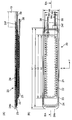
- FIG. 3B is a diagram showing a planar layout when the cuff structure in FIG. 2 is in an unfolded state with its inner peripheral surface as the forefront.
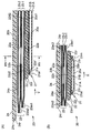
- FIG. 3A is a view showing a cross section taken along line IIIA-IIIA in FIG.
- FIG. 4A is an enlarged view showing the vicinity of the tip of the cuff structure in FIG.
- FIG. 4B is a diagram showing a cross section taken along line IVB-IVB in FIG.
- FIG. 5A is a diagram showing a planar layout of the press cuff included in the cuff structure.
- FIG. 5B is a diagram showing a planar layout of the back plate included in the cuff structure with the pressing cuff as a background. It is a figure which shows the back side of the main body of the said sphygmomanometer seen from the diagonal. It is a figure which shows the back side of the said main body including the curler contained in the above-mentioned cuff structure in the decomposition
- FIG. 15 is a view showing a cross section (corresponding to a cross section taken along line XVA-XVA in FIG. 14) of a portion through which a tendon of the left wrist passes under pressure.
- FIG. 15 is a view showing a cross section (corresponding to a cross section taken along line XVB-XVB in FIG. 14) of a portion through which the radial artery of the left wrist passes in a pressurized state. It is a figure which illustrates pressure Pc and pulse wave signal Pm of the sensing cuff detected by the 2nd pressure sensor carried in the above-mentioned main part. It is a figure which shows blood pressure measurement error when using water as the fluid for pressure transmission accommodated in the said sensing cuff, and variably setting the amount of water accommodated in the said sensing cuff.
- FIG. 1 shows the appearance of a sphygmomanometer according to an embodiment of the present invention (the whole is denoted by reference numeral 1) as viewed obliquely with the belt 2 fastened.
- FIG. 2 shows the appearance of the sphygmomanometer 1 as viewed obliquely with the belt 2 opened.
- the sphygmomanometer 1 is broadly divided into a main body 10 and a body to be measured (in this example, a left hand as a site to be measured as shown in FIG. 13C to be described later).
- the dimension in the width direction X of the belt 2 is set to 29 mm in this example. Further, the thickness of the belt 2 is set to 2 mm in this example.
- the main body 10 includes a substantially short cylindrical case 10B, a circular glass 10A attached to the upper part of the case 10B (in FIGS. 1 and 2), and a back cover attached to the lower part of the case 10B. 10C (see FIG. 6).
- a pair of left and right (in FIGS. 1 and 2) protruding lugs 10B1, 10B2; 10B3, 10B4 for attaching the belt 2 are integrally provided on the side surface of the case 10B.
- a display 50 that forms a display screen is provided in the glass 10A at the top of the case 10B.
- a measurement switch 52A for instructing the start or stop of blood pressure measurement and a display screen of the display 50 are returned to a predetermined home screen.
- Home switch 52B, and a recording call switch 52C for instructing display unit 50 to display past measurement records such as blood pressure and activity (these switches are collectively referred to as operation unit 52).
- a blood pressure measuring element including a pump 30 is mounted inside the main body 10 (described in detail later).
- the sphygmomanometer 1 includes functions of an activity meter and a pulse meter. That is, the sphygmomanometer 1 is configured as a multifunctional device having a wristwatch-type wearable device.
- the main body 10 is small and thin so as not to disturb the daily activities of the user.
- the belt 2 includes a belt-shaped first belt portion 3 extending from the main body 10 to one side in one direction (right side in FIG. 2) and the other side in one direction (in FIG. 2, And a belt-like second belt portion 4 extending to the left side).
- the base portion 3e on the side closer to the main body 10 of the first belt portion 3 is connected to the lugs 10B1 and 10B2 of the main body 10 via a connecting rod 7 (known spring rod) extending in the belt width direction X. As shown by a double arrow A, it is rotatably attached.
- a base portion 4e on the side closer to the main body 10 in the second belt portion 4 is connected to a lug 10B3, 10B4 of the main body 10 in a belt width direction X (a connecting rod 8 (known spring bar)). As shown by a double arrow B, it is rotatably attached.
- a buckle 5 is attached to the distal end portion 3 f of the first belt portion 3 on the side far from the main body 10.
- the buckle 5 is of a known type, and includes a substantially U-shaped frame-like body 5A, a stick 5B, and a connecting rod 5C extending in the belt width direction X.
- the frame-like body 5A and the stick 5B are attached to the tip 3f of the first belt portion 3 on the side far from the main body 10 so as to be rotatable as indicated by a double arrow C via the connecting rod 5C. ing.
- a ring shape is provided at a predetermined position in the longitudinal direction of the first belt portion 3 (corresponding to the circumferential direction Y of the left wrist 90).
- the belt holding portions 6A and 6B are integrally provided.
- the inner peripheral surface 3a of the first belt portion 3 does not protrude toward the inner peripheral side at the belt holding portions 6A and 6B, and is formed substantially flat (curved as a whole, but locally). . Thereby, it is intended that the belt 2 uniformly surrounds and restrains the outer peripheral side of the cuff structure 20.
- a plurality of small holes 4w, 4w,... Penetrate in the thickness direction of the second belt portion 4 between the root portion 4e of the second belt portion 4 and the tip portion 4f far from the main body 10. Is formed.
- a portion connected to the front end portion 4f of the second belt portion 4 is passed through the frame-like body 5A of the buckle 5, and a plurality of second belt portions 4 are provided.
- the first belt portion 3 and the second belt portion 4 constituting the belt 2 are flexible in the thickness direction and substantially in the longitudinal direction (corresponding to the circumferential direction Y of the left wrist 90). It is made of a plastic material that exhibits non-stretchability. Accordingly, the belt 2 can easily surround and restrain the outer peripheral side of the cuff structure 20 when being worn, and can also assist the compression of the left wrist 90 during blood pressure measurement described later.
- the 1st belt part 3 and the 2nd belt part 4 may consist of leather materials.
- the frame 5A and the stick 5B constituting the buckle 5 are made of a metal material in this example, but may be made of a plastic material.
- the cuff structure 20 includes a curler 24 disposed on the outermost periphery, a press cuff 23 disposed along the inner peripheral surface of the curler 24, and an inner peripheral surface of the press cuff 23.
- a back plate 22 as a reinforcing plate arranged along the back plate 22 and a sensing cuff 21 arranged along the inner peripheral surface of the back plate 22 are included.
- the belt 2, the curler 24, the pressing cuff 23, and the back plate described above function as a pressing member that can generate a pressing force toward the wrist, and the sensing cuff 21 is configured by these pressing members. Squeeze your wrist through.
- FIG. 3B shows a planar layout when the cuff structure 20 in FIG. 2 is in an unfolded state with the inner peripheral surface 20a being the foremost surface.
- FIG. 3A shows a cross section taken along line IIIA-IIIA in FIG.
- FIG. 4A shows an enlarged view of the vicinity of the tip of the cuff structure 20 in FIG.
- FIG. 4B shows a cross section taken along line IVB-IVB in FIG.
- FIG. 5A shows a planar layout of the press cuff 23.
- FIG. 5B shows a planar layout of the back plate 22 with the pressing cuff 23 as a background.
- the curler 24, the press cuff 23, the back plate 22, and the sensing cuff 21 each have a strip shape that is elongated in one direction (Y direction).
- the sensing cuff 21 includes a first sheet 21A that is in contact with the left wrist 90, and a second sheet 21B that faces the first sheet 21A. including.
- the second sheet 21B is disposed so as to face the inner peripheral surface of the back plate 22 that forms the pressing member.
- the peripheral portions 21m of the first and second sheets 21A and 21B are brought into close contact with each other by welding to form a bag shape.
- FIG. 4 (B) along the longitudinal direction Y of the sensing cuff 21 in a natural state, at a position connected to the edge portions 21m and 21m on both sides with respect to the width direction X of the sensing cuff 21.
- the slacks 21r and 21r are provided to extend. Further, as shown in FIG. 4A, in the first sheet 21A, the edge portions 21m on both sides with respect to the longitudinal direction Y of the sensing cuff 21 (only the leading end side is shown in FIG. 4A). In a natural state, a slack 21r extending along the width direction X of the sensing cuff 21 is provided at a location that continues to. Such a slack 21r can be formed by a known method, for example, when the peripheral portions 21m of the first and second sheets 21A and 21B are welded to each other. As can be seen from FIGS.
- the end of the sensing cuff 21 in the longitudinal direction Y has a pressure transmission fluid (in this example, to the sensing cuff 21).
- Air or a flexible tube 38 for discharging the pressure transmission fluid from the sensing cuff 21 is attached.
- An inner peripheral surface 20 a of the cuff structure 20 is configured by the first sheet 21 ⁇ / b> A of the sensing cuff 21.
- contact includes not only direct contact but also indirectly contact through another member (for example, a cover member).
- the pressing cuff 23 includes two fluid bags 23-1 and 23-2 stacked in the thickness direction, as can be seen from FIGS. 4 (A) and 4 (B).
- the dimension in the longitudinal direction Y of the inner circumferential fluid bag 23-1 is slightly smaller than the dimension (L2) in the longitudinal direction Y of the outer circumferential fluid bag 23-2. Is set.
- a pressure transmission fluid (air in this example) is supplied to the pressure cuff 23 at the end on the base side (+ Y side) with respect to the longitudinal direction Y of the fluid bag 23-2 on the outer peripheral side, or the pressure cuff A flexible tube 39 for discharging a fluid for pressure transmission from 23 is attached. Further, a plurality of (four in this example) through holes 23o, 23o,... Are formed between the inner peripheral fluid bag 23-1 and the adjacent outer peripheral fluid bag 23-2. Yes. Thereby, a fluid for pressurization (air in this example) can be circulated between the two fluid bags 23-1, 23-2 through the through holes 23o, 23o,.
- the back plate 22 is made of a plate-like resin (in this example, polypropylene) having a thickness of about 1 mm in this example. As can be seen from FIGS. 3 (A) and 3 (B), the back plate 22 extends in a band shape beyond the length of the sensing cuff 21 in the longitudinal direction Y (corresponding to the circumferential direction of the left wrist 90). Yes. Therefore, the back plate 22 works as a reinforcing plate and can transmit the pressing force from the pressing cuff 23 to the entire area in the longitudinal direction Y of the sensing cuff 21 (corresponding to the circumferential direction of the left wrist 90).
- a plate-like resin in this example, polypropylene
- the inner surface 22a and the outer surface 22b of the back plate 22 have grooves 22d1, which are V-shaped or U-shaped in cross section extending in the width direction X.
- a plurality of 22d2 are provided in parallel with each other in the longitudinal direction Y so as to be separated from each other.
- the grooves 22d1 and 22d2 are provided at the same position corresponding to each other between the inner peripheral surface 22a and the outer peripheral surface 22b of the back plate 22.
- the back plate 22 is thinner at the locations of the grooves 22d1 and 22d2 than at other locations, and is easily bent. Accordingly, when the user puts the left wrist 90 and the cuff structure 20 together with the belt 2 when wearing (step S22 in FIG. 12 described later), the cuff structure 20 is placed on the left wrist.
- the back plate 22 does not prevent the end plate 90 from bending along the circumferential direction Y.
- the curler 24 is made of a resin plate having a certain degree of flexibility and hardness (in this example, polypropylene) having a thickness of about 1 mm in this example.
- the curler 24 extends in a band shape beyond the length of the pressing cuff 23 in the longitudinal direction Y (corresponding to the circumferential direction of the left wrist 90) in the deployed state. Exist.
- the curler 24 has a curved shape along the circumferential direction Y surrounding the left wrist 90 in a natural state. Thereby, the shape of the cuff structure 20 in the natural state is maintained in a curved state along the circumferential direction Y of the left wrist 90 as shown in FIG.
- a back cover 10 ⁇ / b> C is provided on the back side of the main body 10.
- the back cover 10C has four through holes 10C1, 10C2, 10C3, and 10C4, and is fixed to the back side of the case 10B with screws (not shown) through these through holes 10C1, 10C2, 10C3, and 10C4.
- a portion of the side surface of the case 10B concealed by the base portion 3e of the first belt portion 3 is provided with filter-equipped intake / exhaust holes 10Bo, 10Bo,... (The same applies to the portion concealed by the base portion 4e of the second belt portion 4). ).
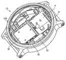
- FIG. 7 shows the back side of the main body 10 with the above-described curler 24 in an exploded state with the back cover 10C removed.
- An inner case member 11 for mounting a blood pressure measurement element is housed in the case 10B of the main body 10.
- An annular groove 11d is formed on the back side of the inner case member 11 so as to surround the protrusion 11p.
- a ring 24o having a shape corresponding to the annular groove 11d is formed in the root portion 24f of the curler 24.
- one end 20 f of the cuff structure 20 (the root portion 24 f of the curler 24) is attached to the main body 10.
- the other end 20e of the cuff structure 20 (the tip 24e of the curler 24) is a free end.
- the cuff structure 20 faces the inner peripheral surfaces 3a and 4a of the belt 2 and can be separated from the inner peripheral surfaces 3a and 4a.
- the cuff structure 20 When the cuff structure 20 is attached to the main body 10 in this way, the one end 20f of the cuff structure 20 is securely held by the main body 10.
- the cuff structure 20 can be exchanged for the main body 10 regardless of the belt 2 by opening the back cover 10 ⁇ / b> C of the main body 10.
- the dimension in the longitudinal direction Y (corresponding to the circumferential direction of the left wrist 90) of the cuff structure 20 can be set to an optimum dimension regardless of the belt 2.
- the main body 10 and the belt 2 are formed separately from each other, and the belt 2 is attached to the main body 10. Therefore, during maintenance service, regardless of the cuff structure 20, The belt 2 can be exchanged with respect to the main body 10.
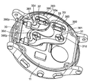
- the first flow path forming member 390 shown in FIG. 7 includes two sheet plates 391 and 392 that are opposed to each other and spread in a thin plate shape, and a predetermined distance between these sheet plates 391 and 392 (this example Then, the spacer portion 393 is maintained at 0.7 mm.
- the second flow path forming member 380 includes two sheet plates 381 and 382 that spread in a thin plate shape facing each other, and a spacer portion 383 that keeps these sheet plates 381 and 382 at a predetermined interval. It is made up of. Note that the sheet plate 381 and the spacer portion 383 are shown in FIG. 9 (in FIG. 9, the illustration of the sheet plates 392 and 382 on the side far from the inner case member 11 is omitted for easy understanding).
- Lateral pins 390p and 380p are integrally attached to the end of the first flow path forming member 390 and the end of the second flow path forming member 380 so as to allow fluid flow, respectively.
- the flexible tube 39 from the pressing cuff 23 is connected to the first flow path forming member 390 via the lateral pin 390p.
- the flexible tube 38 from the sensing cuff 21 is connected to the second flow path forming member 380 via the lateral pin 380p.
- the first flow path forming member 390 and the second flow path forming member 380 are formed by integral molding of elastomer.
- the thickness dimension of the first flow path forming member 390 and the second flow path forming member 380 is set to 1.2 mm.
- FIG. 10 shows a block configuration of a control system of the sphygmomanometer 1.
- the main body 10 of the sphygmomanometer 1 includes a main CPU (Central Processing Unit) 100 as a control unit and a sub CPU 101 as blood pressure measurement elements for executing blood pressure measurement in addition to the display 50 and the operation unit 52 described above.
- a memory 51 as a storage unit, an acceleration sensor 54, a communication unit 59, a battery 53, a first pressure sensor 31 for detecting the pressure of the pressing cuff 23, and a second pressure sensor 32 for detecting the pressure of the sensing cuff 21.
- a pump 30, an on-off valve 33, and a pump drive circuit 35 for driving the pump 30 are mounted.
- the main CPU 100 mainly controls the entire operation of the sphygmomanometer 1, and the sub CPU 101 mainly controls the operation of the air system.
- the main CPU 100 and the sub CPU 101 are simply referred to as a CPU 100.
- the display 50 is an LCD (Liquid Cristal Display), and displays information related to blood pressure measurement such as a blood pressure measurement result and other information according to a control signal from the CPU 100.
- the display device 50 is not limited to an organic EL display, and may include another type of display device 50 such as an organic EL (Electro-Luminescence) display.
- the display device 50 may include an LED (Light (Emitting Diode).
- the operation unit 52 includes a measurement switch 52A for instructing start or stop of blood pressure measurement, a home switch 52B for returning the display screen of the display 50 to a predetermined home screen, A recording call switch 52C for instructing the display 50 to display measurement records such as blood pressure and activity amount.
- these switches 52A to 52C are push-type switches, and input an operation signal in accordance with an instruction to start or stop blood pressure measurement by the user to the CPU 100.
- the operation unit 52 is not limited to a push-type switch, and may be, for example, a pressure-sensitive (resistance) or proximity (capacitance) touch panel switch.
- a microphone (not shown) may be provided, and a blood pressure measurement start instruction may be input by a user's voice.
- the memory 51 includes data of a program for controlling the sphygmomanometer 1, data used for controlling the sphygmomanometer 1, setting data for setting various functions of the sphygmomanometer 1, data of measurement results of the blood pressure value, etc. Is stored temporarily.
- the memory 51 is used as a work memory when the program is executed.
- the CPU100 performs various functions as a control part according to the program for controlling the blood pressure meter 1 memorize
- FIG. For example, when executing the blood pressure measurement function, the CPU 100, based on signals from the first pressure sensor 31 and the second pressure sensor 32, in response to an instruction to start blood pressure measurement from the measurement switch 52A of the operation unit 52, Control for driving the pump 30 and the on-off valve 33 is performed. Further, the CPU 100 performs control to calculate a blood pressure value, a pulse, and the like based on a signal from the second pressure sensor 32.
- the acceleration sensor 54 is composed of a three-axis acceleration sensor integrated in the main body 10.
- the acceleration sensor 54 outputs to the CPU 100 an acceleration signal representing the acceleration of the main body 10 in three directions orthogonal to each other.
- the output of the acceleration sensor 54 is used to measure the amount of activity.
- the communication unit 59 is controlled by the CPU 100 to transmit predetermined information to an external device via a network, or receives information from an external device via the network and passes it to the CPU 100. Communication via this network may be either wireless or wired.
- the network is the Internet, but is not limited to this, and may be another type of network such as an in-hospital LAN (Local Area Network), or a pair using a USB cable or the like. 1 communication may be sufficient.
- the communication unit 59 may include a micro USB connector.
- the battery 53 is a rechargeable secondary battery.
- the battery 53 is an element mounted on the main body 10, in this example, the CPU 100, the memory 51, the acceleration sensor 54, the communication unit 59, the first pressure sensor 31, the second pressure sensor 32, the pump 30, the on-off valve 33, and Electric power is supplied to each element of the pump drive circuit 35.
- the pump 30 is a piezoelectric pump in this example, and is driven by a pump driving circuit 35 based on a control signal given from the CPU 100.
- the pump 30 is connected to the pressing cuff 23 through the first flow path forming member 390 and the flexible tube 39 constituting the first flow path so that fluid can flow.
- the pump 30 can supply air as a pressurizing fluid to the pressing cuff 23 through the first flow path forming member 390 and the flexible tube 39.
- the pump 30 is equipped with an exhaust valve (not shown) that is controlled to open and close as the pump 30 is turned on / off.
- the exhaust valve closes when the pump 30 is turned on and helps to enclose air in the pressure cuff 23, while it opens when the pump 30 is turned off to allow the air in the pressure cuff 23 to be flexible.
- the gas is discharged into the atmosphere through the tube 39 and the first flow path forming member 390.
- the exhaust valve has a check valve function, and the exhausted air does not flow backward.
- the pump 30 is connected to the sensing cuff 21 through the second flow path forming member 380 constituting the second flow path and the flexible tube 38 so that fluid can flow.
- An open / close valve (in this example, a normally open electromagnetic valve) 33 is interposed in the second flow path (actually, between the first flow path forming member 390 and the second flow path forming member 380). It is inserted.
- the on-off valve 33 is controlled to open and close (opening) based on a control signal given from the CPU 100. When the on-off valve 33 is in an open state, air can be supplied from the pump 30 to the sensing cuff 21 through the second flow path as a pressure transmitting fluid and stored.
- the first pressure sensor 31 and the second pressure sensor 32 are each composed of a piezoresistive pressure sensor in this example.
- the first pressure sensor 31 detects the pressure in the pressing cuff 23 via the first flow path forming member 390 and the flexible tube 39 that constitute the first flow path.
- the second pressure sensor 32 detects the pressure in the sensing cuff 21 via the second flow path forming member 380 and the flexible tube 38 constituting the second flow path.
- the pump 30 and the first pressure sensor 31 are arranged at the approximate center of the inner case member 11 within the main body 10.
- the on-off valve 33 and the second pressure sensor 32 are arranged around the inner case member 11.
- the first flow path forming member 390 is disposed on the back side of the inner case member 11 and the discharge port 30d of the pump 30 and the first pressure sensor.
- the air inlet 31d of 31 and the inlet 33i of the on-off valve 33 are arranged.
- the second flow path forming member 380 is disposed on the back side of the inner case member 11 so as to straddle the outlet 33 e of the on-off valve 33 and the air inlet 32 d of the second pressure sensor 32.
- the sphygmomanometer 1 is configured in a small and integrated manner by mounting the blood pressure measuring element as described above on the main body 10. Therefore, user convenience is good.
- FIG. 11 shows an operation flow when the user performs blood pressure measurement by executing the blood pressure measurement method of the embodiment with the sphygmomanometer 1.
- the user wears the sphygmomanometer 1 on the left wrist 90 as a measurement site.
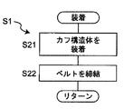
- the user wears the cuff structure 20 on the left wrist 90 using the right hand 99 (step S21 in FIG. 12).
- the cuff structure 20 is curved along the circumferential direction Y of the left wrist 90 by the curler 24 in a natural state. Therefore, in this example, the user fits the cuff structure 20 on the outer peripheral surface of the left wrist 90 using the right half body hand (in this example, the right hand 99) opposite to the left half body to which the left wrist 90 belongs.
- the cuff structure 20 can be easily attached to the left wrist 90.
- the cuff structure 20 In a state where the cuff structure 20 is attached to the left wrist 90, even if the user releases the right hand 99 from the cuff structure 20, the cuff structure 20 grips the left wrist 90.
- the body 20 (and the belt 2, the main body 10) is difficult to drop off.
- the user uses the right hand 99 to bring the belt 2 around the left wrist 90 and the cuff structure 20 together.
- a portion connected to the front end portion 4f of the second belt portion 4 is passed through the frame-like body 5A of the buckle 5 of the first belt portion 3, and a plurality of small holes 4w, 4w,.
- a stick 5B with a buckle 5 is inserted into any one of the above.
- the 1st belt part 3 and the 2nd belt part 4 are fastened (step S22 in FIG. 12).
- the belt 2 extending from the main body 10 surrounds the left wrist 90, and the band-shaped cuff structure 20 having one end 20 f attached to the main body 10 is arranged closer to the left wrist 90 than the belt 2. It becomes a state.
- the cuff structure 20 can be separated from the inner peripheral surfaces 3a and 4a of the belt 2, and the other end 20e on the side opposite to the one end 20f of the cuff structure 20 is a free end. ing. Accordingly, when the first belt portion 3 and the second belt portion 4 are fastened, the cuff structure 20 receives an inward force from the belt 2 and just follows the outer peripheral surface of the left wrist 90. 20 can slide or deform. Thereby, in the wearing state, the cuff structure 20 and the belt 2 are in close contact with the outer peripheral surface of the left wrist 90 in this order, that is, the left wrist 90 is surrounded as a whole in a band shape. In this manner, the sphygmomanometer 1 can be easily attached to the left wrist 90.
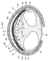
- the bag-shaped pressing cuff 23 extends along the circumferential direction Y of the left wrist 90 on the inner peripheral side of the curler 24 included in the cuff structure 20.
- the bag-like sensing cuff 21 included in the cuff structure 20 is arranged on the inner peripheral side of the pressing cuff 23 so as to contact the left wrist 90 and cross the artery passing portion 90a of the left wrist 90. It extends in the circumferential direction Y.
- a back plate 22 included in the cuff structure 20 is inserted between the pressing cuff 23 and the sensing cuff 21 and extends along the circumferential direction Y of the left wrist 90.
- the main body 10 and the belt 2 are not shown.
- the radius 93, ulna 94, radial artery 91, ulnar artery 92, and tendon 96 of the left wrist 90 are shown.
- step S2 in FIG. 11 when the user presses the measurement switch 52A of the operation unit 52 provided in the main body 10 (step S2 in FIG. 11), the CPU 100 initializes the processing memory area (step S3 in FIG. 11). In addition, the CPU 100 turns off the pump 30 via the pump drive circuit 35, opens the exhaust valve built in the pump 30, and maintains the on-off valve 33 in the open state so that the inside of the pressing cuff 23 and the sensing cuff 21 Exhaust the air. Subsequently, the control for adjusting 0 mmHg of the first pressure sensor 31 and the second pressure sensor 32 is performed.
- the CPU 100 operates as a pressurization control unit and a fluid accommodation control unit, turns on the pump 30 via the pump drive circuit 35 (step S4 in FIG. 11), maintains the open / close valve 33 in the open state, and presses the pump 30 Pressurization of the cuff 23 and the sensing cuff 21 is started (step S5 in FIG. 11).
- the pump 30 is driven via the pump drive circuit 35 while monitoring the pressure of the pressure cuff 23 and the sensing cuff 21 by the first pressure sensor 31 and the second pressure sensor 32, respectively.
- the first flow path (the first flow path forming member 390 and the flexible tube 39) is passed through the pressing cuff 23, and the second flow path (the second flow path forming member 380 and the flexible tube 39 is flexible). Control is performed to send air to the sensing cuff 21 through the tube 38).
- step S6 in FIG. 11 the CPU 100 operates as a fluid accommodation control unit, and the pressure of the sensing cuff 21 has reached a predetermined pressure (15 mmHg in this example) or the driving time of the pump 30 is predetermined. It is determined whether or not only the time (3 seconds in this example) has elapsed. The reason for making this determination is to confirm whether or not an appropriate amount of air is contained in the sensing cuff 21. If NO in step S6 of FIG. 11, the process waits until the pressure of the sensing cuff 21 reaches a predetermined pressure or until the driving time of the pump 30 has elapsed for a predetermined time. The amount of the “appropriate amount” of the pressure transmitting fluid stored in the sensing cuff 21 will be described later.
- step S6 in FIG. 11 If “YES” in the step S6 in FIG. 11, it is determined that an appropriate amount of air is accommodated in the sensing cuff 21. Then, in step S7 in FIG. 11, the CPU 100 operates as a pressurization control unit, keeps the on-off valve 33 in a closed state, and continues control for supplying air from the pump 30 to the pressing cuff 23 through the first flow path. As a result, the pressure cuff 23 is expanded and the pressure is gradually increased to press the left wrist 90. At this time, the back plate 22 transmits the pressing force from the pressing cuff 23 to the sensing cuff 21. The sensing cuff 21 presses the left wrist 90 (including the artery passage portion 90a).
- the CPU 100 monitors the pressure Pc of the sensing cuff 21, that is, the pressure of the arterial passage portion 90a of the left wrist 90 with the second pressure sensor 32 in order to calculate the blood pressure value.
- the pulse wave signal Pm is acquired.
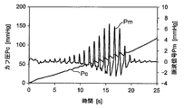
- FIG. 16 illustrates the waveforms of the pressure Pc and pulse wave signal Pm of the sensing cuff 21 obtained in this pressurization process.
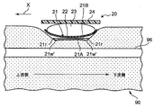
- FIG. 15A and 15B show the longitudinal direction of the left wrist 90 (corresponding to the width direction X of the cuff) in a pressurized state in which an appropriate amount of air is accommodated in the sensing cuff 21 and the on-off valve 33 is closed.
- the cross section along is shown typically.
- FIG. 15A shows a cross section (corresponding to a cross section taken along line XVA-XVA in FIG. 14) of a portion through which the tendon 96 of the left wrist 90 passes.
- FIG. 15B shows a cross section (corresponding to a cross section taken along line XVB-XVB in FIG. 14) of the portion of the left wrist 90 through which the radial artery 91 passes.
- FIG. 15A shows a cross section (corresponding to a cross section taken along line XVA-XVA in FIG. 14) of a portion through which the tendon 96 of the left wrist 90 passes.
- FIG. 15B shows a cross section (corresponding to a cross section taken along line XVB-XVB
- the portion through which the radial artery 91 of the left wrist 90 passes is relatively soft, so that there is a gap 21w where air exists between the first sheet 21A and the second sheet 21B of the sensing cuff 21. Remaining. Therefore, the portion of the sensing cuff 21 that faces the radial artery 91 can reflect the pressure of the artery passing portion 90 a of the left wrist 90.
- the portion through which the tendon 96 of the left wrist 90 passes is relatively hard. Therefore, in the portion corresponding to the approximate center in the width direction X of the sensing cuff 21, the first sheet 21 ⁇ / b> A and the second sheet The sheet 21B is in contact with each other.
- the slack 21r extending along the longitudinal direction Y (corresponding to the circumferential direction of the left wrist 90) as described above. Since 21r is provided, gaps 21w ′ and 21w ′ in which air exists along the longitudinal direction Y remain. As a result, the air stored in the sensing cuff 21 can flow along the longitudinal direction Y of the sensing cuff 21 through the gaps 21w ′ and 21w ′. Accordingly, the sensing cuff 21 can successfully transmit the pressure applied to the artery passage portion 90a of the left wrist 90 to the second pressure sensor 32 in the main body 10 as the pressure of air (pressure transmission fluid). .
- step S8 of FIG. 11 the CPU 100 operates as a blood pressure calculation unit, and applies a known algorithm by an oscillometric method based on the pulse wave signal Pm acquired at this time point to determine the blood pressure value (systolic period). Attempts to calculate blood pressure SBP and diastolic blood pressure DBP).
- the cuff pressure has reached the upper limit pressure (for example, 300 mmHg is determined in advance for safety). Unless otherwise specified, the processes in steps S7 to S9 are repeated.
- step S9 the CPU 100 stops the pump 30 (step S10), opens the on-off valve 33 (step S11), and within the press cuff 23, the sensing cuff 21. Control to exhaust the air inside. Finally, the measurement result of the blood pressure value is displayed on the display device 50 (step S12).
- the blood pressure calculation may be performed not in the pressurizing process of the pressing cuff 23 but in the depressurizing process.
- the second pressure sensor 32 is separated from the pressure cuff 23 by the pressure Pc of the sensing cuff 21, that is, the left wrist 90
- the pressure of the arterial passage portion 90a is detected. Therefore, as a result of setting the dimension in the width direction X of the belt 2 and the cuff structure 20 (simply referred to as “cuff” where appropriate) to a small size (for example, about 25 mm), the pressure cuff 23 is moved in the thickness direction during pressurization. Even in the case where compression loss occurs due to large expansion, blood pressure can be measured with high accuracy.
- the sensing cuff 21 extends in the circumferential direction Y so as to cross the arterial passage portion 90 a of the left wrist 90. Accordingly, when the user actually wears the sphygmomanometer 1 on the left wrist 90, even if the cuff is displaced to some extent with the main body 10 in the circumferential direction Y of the left wrist 90, the arteries passing portion 90a of the left wrist 90 The sensing cuff 21 does not come off. Therefore, it is possible to prevent the blood pressure measurement value from varying from the actual blood pressure, and as a result, the blood pressure can be measured with high accuracy.
- the sensing cuff 21 may contain a fluid for pressure transmission and may be sealed.
- the sensing cuff 21 is in close contact with the outer peripheral surface of the left wrist 90.
- the sensing cuff 21 can be roughly divided into five regions. These five regions are the region F1 corresponding to the ulna 94, the region F2 corresponding to the ulnar artery 92, the region F3 corresponding to the tendon, and the region corresponding to the radial artery 91, as shown by the dotted ellipse in FIG. F4 and the region F5 corresponding to the rib 93.
- the region F1 corresponding to the ulna 94, the region F3 corresponding to the tendon, and the region F4 corresponding to the radial artery 91 are the ulna 94, the tendon 96, and the rib 93, respectively, of the measurement site.
- This is a region corresponding to a hard part.
- a region F2 corresponding to the ulnar artery 92 and a region F4 corresponding to the radial artery 91 are regions corresponding to soft portions in which the ulnar artery 92 and the radial artery 91 are present, respectively.
- the fluid is contained in the region F1, the region F2, the region F3, the region F4, and the region F5 so that the sensing cuff 21 swells, when the sensing cuff 21 is pressed against the wrist.
- the repulsive force from all regions is detected by the second pressure sensor 32 as the internal pressure of the sensing cuff 21, and the blood pressure value is calculated.
- the region F1, the region F3, and the region F5 correspond to the hard portions where the ulna 94, the tendon 96, and the radius 93 are present, the repulsive force from these hard portions against the pressing force is the ulnar artery. It becomes higher than the repulsive force from the soft part near 92 and the radial artery 91.
- the internal pressure of the sensing cuff 21 as a whole becomes higher than the pressure in the vicinity of the ulnar artery 92 and the radial artery 91, and the error in the blood pressure value increases.
- the amount of fluid stored in the sensing cuff 21 is also related to the generation of tension in the first sheet 21A and the second sheet 21B constituting the sensing cuff 21, and the tension increases as the amount of fluid increases.
- the internal pressure of the sensing cuff 21 increases, and in this case also, the error in the blood pressure value increases. As described above, when the fluid is contained in the region F1, the region F3, and the region F5, the internal pressure increases due to the influence of the repulsive force and the tension, and the error of the blood pressure value increases.
- the first sheet 21A and the second sheet 21B are in contact, and in the region F2 and the region F4, the first sheet 21A.
- the fluid is supplied until the second sheet 21B is separated from the second sheet 21B, the influence from the hard part described above is eliminated. That is, when the amount of fluid is about this level, when the sensing cuff 21 is pressed against the wrist, there is no fluid in the region F1, the region F3, and the region F5 corresponding to the hard portion described above (they exist temporarily).
- the sensing cuff 21 extends along the longitudinal direction Y (corresponding to the circumferential direction of the left wrist 90) as shown in FIG. Since the slacks 21r and 21r extending in this manner are provided, the gaps 21w ′ and 21w ′ remain along the longitudinal direction Y.
- the fluid accommodated in the sensing cuff 21 flows through the gaps 21w ′ and 21w ′ to the region F2 and the region F3, and the fluid flows to the region F2 and the region F3. Be contained.
- the first sheet 21A and the second sheet 21B are shown slightly apart from each other. The sheet 21B is in contact.
- the first sheet 21A and the second sheet 21B of the sensing cuff 21 are separated from each other. Fluid is contained until Therefore, the pressure around the radial artery 91 and the ulnar artery 92 is detected as the internal pressure of the sensing cuff 21.
- the internal pressure of the sensing cuff 21 is a region corresponding exclusively to the soft portion where the two arteries, the radial artery 91 and the ulnar artery 92 are present. Since it is detected from F2 and the region F4, the internal pressure of the sensing cuff 21 and the pressure around the radial artery 91 and the ulnar artery 92 can be made equal, and the error of the blood pressure value becomes small.
- FIG. 17 shows blood pressure measurement error (average value) when water is used as the pressure transmission fluid stored in the sensing cuff 21 and the amount of water stored in the sensing cuff 21 is variably set.
- the blood pressure measurement error is a blood pressure value measured by a standard (accurate) sphygmomanometer from a blood pressure value (systolic blood pressure SBP) measured by the sphygmomanometer 1 for a certain user (subject). It means the difference obtained by subtracting the systolic blood pressure SBP) (this is referred to as “reference blood pressure value”).
- (Blood pressure measurement error) (blood pressure value measured by sphygmomanometer 1) ⁇ (reference blood pressure value) It is. As can be seen from FIG. 17, if the amount of water stored in the sensing cuff 21 is in the range wa of 0.26 ml ⁇ 0.05 ml, the blood pressure measurement error is within ⁇ 5 mmHg, which is considered to be an appropriate amount.
- the present inventor conducted a similar experiment on a plurality of users. As long as the amount of fluid is within the above range wa, the blood pressure measurement error is within ⁇ 5 mmHg, and in the region F1, the region F3, and the region F5, It has been found that the first sheet 21A and the second sheet 21B are in contact with each other, and the first sheet 21A and the second sheet 21B can be separated from each other in the region F2 and the region F4. Further, in the process shown in step S6 of FIG. 11, the amount of fluid in the above range wa is supplied until the pressure of the sensing cuff 21 reaches 15 mmHg or when the pump 30 is driven for 3 seconds. I found out that I can do it. Note that the pressure of 15 mmHg and the driving time of 3 seconds are merely examples, and the present invention is not limited to these values.
- the appropriate amount of the pressure transmitting fluid accommodated in the sensing cuff 21 depends on the size of the sensing cuff 21 and the like.
- the pump 30 is driven until the pressure of the sensing cuff 21 reaches 15 mmHg in the pressurizing process of the sensing cuff 21 shown in step S6 of FIG. Is set to 3 seconds, an appropriate amount of fluid, that is, an amount of fluid in the range wa is supplied to the sensing cuff 21.
- the first sheet 21A and the second sheet 21B are in contact with each other in the region F1, the region F3, and the region F5 corresponding to the hard portions where the ulna 94, the tendon 96, and the rib 93 are present.
- the fluid is supplied until the first sheet 21A and the second sheet 21B are separated from each other. ing.
- the internal pressure of the sensing cuff 21 and the pressure around the radial artery 91 and the ulnar artery 92 can be made equal, and the error in blood pressure value is reduced. Therefore, it is possible to prevent the blood pressure measurement value from varying from the actual blood pressure, and as a result, the blood pressure can be measured with high accuracy.
- the scatter diagram of FIG. 18 shows the fluid for pressure transmission accommodated in the sensing cuff 21 for a plurality of users (in this example, each of five subjects whose systolic blood pressure SBP is measured from 97 mmHg to 149 mmHg).
- the blood pressure measurement error is increased on the plus side for a plurality of users, as indicated by a cross in the figure. If the amount of water is small, the blood pressure measurement error is larger on the minus side for a plurality of users, as indicated by ⁇ in the figure.
- the sphygmomanometer 1 when a plurality of users actually mount the sphygmomanometer 1 on the left wrist 90 and perform blood pressure measurement, the areas of the soft portions where the two arteries, the radial artery 91 and the ulnar artery 92, are different depending on the user. .
- the amount of water is an appropriate amount, blood pressure measurement errors are suppressed for a plurality of users. Therefore, it can be said that the sphygmomanometer 1 has confirmed that blood pressure can be accurately measured even when the areas of the soft portions where the two arteries, the radial artery 91 and the ulnar artery 92 are present, are different.
- the sensing cuff 21 has been described as an example in which the sensing cuff 21 is in direct contact with the left wrist 90 as the measurement site, but the present invention is not limited to this.
- the sensing cuff 21 may contact the left wrist 90 indirectly via another member (for example, a cover member).
- the measurement site to which the sphygmomanometer is attached is the left wrist 90.
- the sphygmomanometer of the present invention may be configured to be optically symmetric with respect to the sphygmomanometer 1 shown in FIGS. 1 and 2 and attached to the right wrist.
- the part to be measured may be a part other than the wrist such as the upper arm or the lower limb.
- the main body 10 and the belt 2 are formed separately from each other, and the belt 2 is attached to the main body 10.
- the present invention is not limited to this.
- the main body 10 and the belt 2 may be integrally formed.
- the first belt portion 3 and the second belt portion 4 of the belt 2 are fastened or released by the buckle 5.
- the present invention is not limited to this.
- the first belt portion 3 and the second belt portion 4 may be connected to each other via a three-fold buckle that can be opened and closed.
- the belt 2 is formed by a single band-shaped body, the pressing cuff 23 is disposed along the inner circumferential surface of the band-shaped body, and the back plate 22 is disposed along the inner circumferential surface of the pressing cuff 23.
- the sensing cuff 21 may be disposed along the inner peripheral surface of the back plate 22.
- the belt 2, the pressing cuff 23, and the back plate 22 described above function as a pressing member capable of generating a pressing force toward the wrist, and the wrist is moved through the sensing cuff 21 by these pressing members. Squeeze.
- the back cover 10 ⁇ / b> C of the main body 10 may be provided with a three-fold buckle that can be opened and closed, and the end of the belt 2 may be connected to the three-fold buckle.
- the pump 30 is driven until the pressure of the sensing cuff 21 reaches 15 mmHg, or the driving time of the pump 30 is set to 3 Seconds.
- the present invention is not limited to this example.
- the pump 30 is driven until the pressure of the sensing cuff 21 reaches, for example, 5 mmHg, and the sensing cuff 21 is filled with fluid.
- the amount of fluid in 21 may be optimized.
- the pump 30 is filled with air until the pressure reaches a high pressure, for example, 30 mmHg, and then the pump 30 is stopped and the exhaust valve is opened to reduce the pressure of the sensing cuff 21 to a low pressure, for example,
- the pressure in the sensing cuff 21 may be optimized by reducing the pressure to 15 mmHg and then closing the exhaust valve.
- an exhaust valve may be provided separately from the pump 30, and a valve drive circuit for driving the exhaust valve may be provided so as to be controllable by the CPU 100.
- the belt 2, the curler 24, the pressing cuff 23, and the back plate 22 are given as examples of the pressing member.
- the present invention is not limited to this example, and is mechanically expanded in the thickness direction.
- a pressing member may be used.
- the present invention is not limited to this example, and includes a cuff including the belt 2 and the cuff structure 20 and a main body placed on a table.
- the main body may be provided with a pump.
- the cuff and the main body may be connected via an elongated tube, and fluid may be supplied from the main body to the cuff.
- the CPU 100 mounted on the sphygmomanometer 1 functions as a fluid accommodation control unit, a pressurization control unit, and a blood pressure calculation unit to perform blood pressure measurement (operation flow in FIG. 11).
- the present invention is not limited to this.
- a substantial computer device such as a smartphone provided outside the sphygmomanometer 1 works as a fluid accommodation control unit, a pressurization control unit, and a blood pressure calculation unit, and is connected to the sphygmomanometer 1 via the network 900. You may make it perform blood-pressure measurement (operation
Landscapes
- Health & Medical Sciences (AREA)
- Life Sciences & Earth Sciences (AREA)
- Cardiology (AREA)
- Vascular Medicine (AREA)
- Surgery (AREA)
- Public Health (AREA)
- Biomedical Technology (AREA)
- Heart & Thoracic Surgery (AREA)
- Medical Informatics (AREA)
- Molecular Biology (AREA)
- Physics & Mathematics (AREA)
- Animal Behavior & Ethology (AREA)
- General Health & Medical Sciences (AREA)
- Engineering & Computer Science (AREA)
- Veterinary Medicine (AREA)
- Biophysics (AREA)
- Pathology (AREA)
- Physiology (AREA)
- Ophthalmology & Optometry (AREA)
- Dentistry (AREA)
- Measuring Pulse, Heart Rate, Blood Pressure Or Blood Flow (AREA)
Abstract
本発明の血圧計では、センシングカフ(21)は、上記押圧部材の内周面に対向して配置された第2のシート(21B)と、この第2のシート(21B)に対向する第1のシート(21A)とを含み、第1のシート(21A)、第2のシート(21B)の周縁部(21m)が互いに密着されて袋状に構成されている。流体収容制御部としてのCPU(100)は、ベルト(2)を被測定部位としての手首に装着した状態で、尺骨(94)に対応する領域(F1)、橈骨(93)に対応する領域(F5)、および腱(96)に対応する領域(F3)で、第1のシート(21A)と第2のシート(21B)とが接し、橈骨動脈(91)および尺骨動脈(92)の2つの動脈に対応する領域(F4,F2)で第1のシート(21A)と第2のシート(21B)が離間する状態まで流体を供給する。
Description
この発明は血圧計に関し、より詳しくは、被測定部位を取り巻いて装着されるベルトと、ポンプを搭載した本体とを備えた血圧計に関する。また、この発明は、被測定部位の血圧を測定する血圧測定方法に関する。さらに、この発明は、血圧測定機能を備えた機器に関する。
従来、この種の血圧計としては、例えば特許文献1(特開平11-309119号公報)に開示されているように、被測定部位としての手首に巻き付けられるカフと、このカフに一体に取り付けられた本体とを有するものが知られている。この血圧計では、帯状のベルト内に、動脈を圧迫する袋状の血圧測定用カフと、この血圧測定用カフの外側に設けた介在部材と、この介在部材の外側に設けられた袋状の押圧カフとを備え、血圧測定用カフ内の圧力を、本体に搭載された圧力センサで検出する構成になっている。血圧測定時には、上記ベルトが手首を取り巻いて装着された状態で、本体に搭載されたポンプから上記血圧測定用カフへ加圧用の所定量の空気を供給し、その後、押圧カフにも空気を供給して、手首の動脈(橈骨動脈、尺骨動脈)を圧迫する。そして、上記圧力センサの出力に基づいて、オシロメトリック法により血圧測定値が求められる。この血圧計においては、血圧測定用カフに所定量の空気を供給し、生体部位を十分に圧迫する力は介在部材と押圧カフとにより得ることで、カフ装着時の圧迫感や不快感等を解消している。
ところで、上記血圧測定用カフは、動脈を通る血流の脈波を検出するために、被測定部位としての手首のうち、橈骨と橈側手根屈筋の腱との間の橈骨動脈近傍、尺骨と長掌筋の腱との間の尺骨動脈近傍の圧力を検出すべきである(以下では、橈側手根屈筋の腱と長掌筋の腱とを併せて、単に「腱」という。)。
しかしながら、上記血圧計では、血圧測定時において被測定部位としての手首のうち掌側面(手の平側の面)の全域にわたってほぼ平坦に膨らむ程度まで、血圧測定用カフへ空気を供給している。このため、手首のうち橈骨動脈近傍、尺骨動脈近傍のような比較的柔らかい部分だけでなく、橈骨、尺骨、腱のような比較的硬い部分も圧迫している。ここで、手首のうち、橈骨、尺骨、腱のような比較的硬い部分からの反発力は、橈骨動脈近傍、尺骨動脈近傍のような比較的柔らかい部分からの反発力よりも、高い。このため、上記血圧測定用カフの内圧は、上記橈骨動脈近傍、尺骨動脈近傍の圧力よりも、全体として高くなる。その結果、血圧値の測定誤差が大きくなるという問題がある。
しかしながら、上記血圧計では、血圧測定時において被測定部位としての手首のうち掌側面(手の平側の面)の全域にわたってほぼ平坦に膨らむ程度まで、血圧測定用カフへ空気を供給している。このため、手首のうち橈骨動脈近傍、尺骨動脈近傍のような比較的柔らかい部分だけでなく、橈骨、尺骨、腱のような比較的硬い部分も圧迫している。ここで、手首のうち、橈骨、尺骨、腱のような比較的硬い部分からの反発力は、橈骨動脈近傍、尺骨動脈近傍のような比較的柔らかい部分からの反発力よりも、高い。このため、上記血圧測定用カフの内圧は、上記橈骨動脈近傍、尺骨動脈近傍の圧力よりも、全体として高くなる。その結果、血圧値の測定誤差が大きくなるという問題がある。
そこで、この発明の課題は、手首を被測定部位として、袋状の血圧測定用カフを用いて血圧を測定する場合でも、血圧を精度良く測定できる血圧計および血圧測定方法並びに機器を提供することにある。
上記課題を解決するため、この発明の血圧計は、
被測定部位としての手首を周方向に取り巻いて配置され、上記手首へ向かって押圧力を発生可能な押圧部材と、
上記押圧部材の内周面に対向して配置された第2のシートと、この第2のシートに対向する第1のシートとを含み、圧力伝達用の流体を収容可能に袋状に構成され、上記手首の動脈通過部分を横切るように周方向に延在するセンシングカフと、
上記押圧部材によって上記センシングカフを介して上記手首を圧迫する制御を行う加圧制御部と、
上記押圧部材および上記センシングカフが上記手首に装着された装着状態で、上記センシングカフに上記圧力伝達用の流体を供給して収容させる制御を行う流体収容制御部と、
上記センシングカフに収容された上記圧力伝達用の流体の圧力に基づいて血圧を算出する血圧算出部とを備え、
上記流体収容制御部は、上記装着状態で、尺骨に対応する領域、橈骨に対応する領域、および腱に対応する領域で上記第1、第2のシートが接し、橈骨動脈および尺骨動脈の2つの動脈に対応する領域で上記第1、第2のシートが離間する状態まで上記流体を供給する、
ことを特徴とする。
被測定部位としての手首を周方向に取り巻いて配置され、上記手首へ向かって押圧力を発生可能な押圧部材と、
上記押圧部材の内周面に対向して配置された第2のシートと、この第2のシートに対向する第1のシートとを含み、圧力伝達用の流体を収容可能に袋状に構成され、上記手首の動脈通過部分を横切るように周方向に延在するセンシングカフと、
上記押圧部材によって上記センシングカフを介して上記手首を圧迫する制御を行う加圧制御部と、
上記押圧部材および上記センシングカフが上記手首に装着された装着状態で、上記センシングカフに上記圧力伝達用の流体を供給して収容させる制御を行う流体収容制御部と、
上記センシングカフに収容された上記圧力伝達用の流体の圧力に基づいて血圧を算出する血圧算出部とを備え、
上記流体収容制御部は、上記装着状態で、尺骨に対応する領域、橈骨に対応する領域、および腱に対応する領域で上記第1、第2のシートが接し、橈骨動脈および尺骨動脈の2つの動脈に対応する領域で上記第1、第2のシートが離間する状態まで上記流体を供給する、
ことを特徴とする。
加圧用、圧力伝達用の「流体」は、典型的には空気であるが、他の気体、または液体であっても良い。また、「圧力伝達用の流体」は、この血圧計の製造段階で上記センシングカフに収容されても良いし、または、血圧測定の都度、上記センシングカフに収容され、上記センシングカフから排出されても良い。
押圧部材の「内周面」とは、被測定部位を取り巻いた装着状態で内周側となる面を指す。
この発明の血圧計は、上記押圧部材が被測定部位としての上記手首の周方向を取り巻くとともに、上記センシングカフが上記押圧部材の内周面に対向して配置された状態で、上記手首に装着される。この装着状態では、袋状の上記センシングカフが、上記押圧部材よりも内周側に配置されて上記手首に対向し、かつ、上記手首の動脈通過部分を横切るように上記周方向に延在する。
血圧測定時には、例えば、まず流体収容制御部が、上記装着状態で、尺骨に対応する領域、橈骨に対応する領域、および腱に対応する領域で上記第1、第2のシートが接し、橈骨動脈および尺骨動脈の2つの動脈に対応する領域で上記第1、第2のシートが離間する状態まで上記流体を供給する。その状態で、加圧制御部が、上記押圧部材によって上記センシングカフを介して上記手首を圧迫する制御を行う。この結果、上記センシングカフは、上記手首(上記動脈通過部分を含む。)を圧迫する。上記押圧部材の加圧過程または減圧過程で、血圧算出部が、上記センシングカフに収容された上記圧力伝達用の流体の圧力に基づいて血圧を算出する(オシロメトリック法)。
ここで、この血圧計では、上記センシングカフは、上記手首の動脈通過部分に加えられた圧力自体を検出する。この際、上記センシングカフに供給される上記流体の量は、流体収容制御部によって制御され、上記装着状態で、尺骨に対応する領域、橈骨に対応する領域、および腱に対応する領域では、上記センシングカフを構成する上記第1、第2のシートが接し、橈骨動脈および尺骨動脈の2つの動脈に対応する領域では、上記第1、第2のシートが離間する状態となっている。
つまり、上記流体の量は、尺骨、橈骨、および腱が存在する硬い部分に対応する領域には、上記流体が存在せず、橈骨動脈および尺骨動脈の2つの動脈に対応する領域に上記流体が収容される量に制御されている。したがって、上記センシングカフにおけるこれらの硬い部分に対応する領域では、上記尺骨、橈骨、および腱からの反発力は、上記センシングカフの内圧に寄与しない。一方、橈骨動脈および尺骨動脈の2つの動脈が存在する柔らかい部分に対応する領域においては、上記センシングカフの上記第1、第2のシートが離間する状態となるまで上記流体が収容されている。したがって、橈骨動脈および尺骨動脈の周辺の圧力は、上記センシングカフの内圧として検出される。以上のように、上記センシングカフの内圧は、もっぱら、橈骨動脈および尺骨動脈の2つの動脈が存在する柔らかい部分に対応する領域から検出されることになるので、上記センシングカフの内圧と橈骨動脈および尺骨動脈周辺の圧力を等しくすることができ、血圧値の誤差が小さくなる。したがって、実際の血圧に対して血圧測定値がばらつくのを防止でき、この結果、血圧を精度良く測定できる。
また、この血圧計では、流体収容制御部が、上記装着状態で、上記センシングカフに上記圧力伝達用の流体を供給して収容させる制御を行う。したがって、血圧測定の都度、上記センシングカフに上記圧力伝達用の流体を収容できる。なお、血圧測定が終了すれば、上記圧力伝達用の流体は、上記センシングカフから排出されれば良い。
一実施形態の血圧計では、上記センシングカフは、上記第1または第2のシートのうち、このセンシングカフの幅方向に関して両側の縁部に連なる箇所に、自然状態で、このセンシングカフの長手方向に沿って延在する弛みが設けられていることを特徴とする。
上記センシングカフの上記第1または第2のシートの「弛み」は、例えば、上記第1、第2のシートの周縁部を互いに溶着して密着させる際に、形成され得る。
この一実施形態の血圧計では、上記第1または第2のシートのうち、このセンシングカフの幅方向に関して両側の縁部に連なる箇所に、自然状態で、このセンシングカフの長手方向に沿って延在する弛みが設けられている。したがって、上記押圧部材の加圧時に、上記押圧部材と上記手首との間に挟まれて上記センシングカフの上記第1、第2のシートが互いに接する状態になったとしても、上記弛みのおかげで、上記センシングカフの幅方向に関して両側の縁部に連なる箇所に、上記センシングカフの長手方向(上記手首の周方向に相当)に沿って延在する隙間が残る。また、上記流体の量は、流体収容制御部によって制御され、上記装着状態で、尺骨に対応する領域、橈骨に対応する領域、および腱に対応する領域では、上記センシングカフを構成する上記第1、第2のシートが接し、橈骨動脈および尺骨動脈2つの動脈に対応する領域では、上記第1、第2のシートが離間する状態となる量になっている。この結果、上記センシングカフに供給された上記圧力伝達用の流体は、尺骨に対応する領域、橈骨に対応する領域、および腱に対応する領域から、橈骨動脈および尺骨動脈2つの動脈に対応する領域に、上記隙間を通して流通し得る。したがって、上記手首の動脈通過部分に加えられた圧力を、上記圧力伝達用の流体の圧力として上記血圧算出部へ首尾良く伝えることができる。
一実施形態の血圧計では、
上記押圧部材は、
上記手首を周方向に取り巻いて装着されるべきベルトと、
上記ベルトの内周面に対向して配置され、加圧用の流体の供給を受けて上記手首を圧迫するために、上記手首の周方向に沿って延在する袋状の押圧カフと、
上記押圧カフと上記センシングカフとの間に介挿され上記手首の周方向に沿って延在し、上記押圧カフからの押圧力を上記センシングカフへ伝える背板とを含む、
ことを特徴とする。
上記押圧部材は、
上記手首を周方向に取り巻いて装着されるべきベルトと、
上記ベルトの内周面に対向して配置され、加圧用の流体の供給を受けて上記手首を圧迫するために、上記手首の周方向に沿って延在する袋状の押圧カフと、
上記押圧カフと上記センシングカフとの間に介挿され上記手首の周方向に沿って延在し、上記押圧カフからの押圧力を上記センシングカフへ伝える背板とを含む、
ことを特徴とする。
この血圧計は、上記ベルトが上記手首を周方向に取り巻くとともに、上記押圧カフ、上記背板、および上記センシングカフが、この順に、上記ベルトの内周面に対向して配置された状態で、上記手首に装着される。この装着状態では、上記押圧カフが、上記手首の周方向に沿って延在する。また、上記センシングカフが、上記押圧カフよりも内周側に配置されて上記手首に対向し、かつ、上記手首の動脈通過部分を横切るように上記周方向に延在する。さらに、上記背板が、上記押圧カフと上記センシングカフとの間に介挿され上記手首の周方向に沿って延在する。したがって、血圧計のカフを全体として帯状に構成することができ、ユーザの使い勝手が良い血圧計を提供できる。
なお、上記ベルトは、このベルトの厚さ方向に関して可撓性を有し、かつ、このベルトの長手方向(被測定部位の周方向に相当)に関して実質的に非伸縮性を示す材料からなるのが望ましい。これにより、装着の際に上記ベルトが上記の外周側を容易に取り巻いて拘束できるとともに、血圧測定時に手首の圧迫を助けることができる。
一実施形態の血圧計では、
ポンプを搭載した本体を備え、
上記ベルトは、上記本体から延在している、ことを特徴とする。
ポンプを搭載した本体を備え、
上記ベルトは、上記本体から延在している、ことを特徴とする。
本明細書で、「本体から延在」する「ベルト」とは、本体とベルトとが一体成形されていても良いし、または、本体とベルトとが互いに別々に形成され、本体に対してベルトが取り付けられていても良いことを意味する。また、ベルト自体については、上記本体から一方向片側に延在する第1ベルト部と、上記本体から一方向他側に延在する第2ベルト部とが、尾錠によって締結または開放されるようになっていても良いし、または、開閉可能なバックルによって連結されていても良い。
この血圧計では、上記本体に上記ポンプが搭載され、上記本体から延在しているベルトにより簡単に手首に装着できる。したがって、血圧計を小型で一体に構成することができると共に、血圧計を携行することが可能となり、ユーザの使い勝手が良い血圧計を提供できる。
一実施形態の血圧計では、
上記押圧カフ、上記背板、および上記センシングカフは、帯状で、上記本体に一端が取り付けられたカフ構造体を構成し、
このカフ構造体は、さらに、上記押圧カフの外周面に沿って、このカフ構造体の自然状態での形状を、上記手首の周方向に沿って湾曲した状態に保つためのカーラを備えたことを特徴とする。
上記押圧カフ、上記背板、および上記センシングカフは、帯状で、上記本体に一端が取り付けられたカフ構造体を構成し、
このカフ構造体は、さらに、上記押圧カフの外周面に沿って、このカフ構造体の自然状態での形状を、上記手首の周方向に沿って湾曲した状態に保つためのカーラを備えたことを特徴とする。
本明細書で、「カーラ」とは、典型的には或る程度の可撓性および硬さを有する樹脂板からなり、自然状態で被測定部位を取り巻く周方向に沿って湾曲した形状を有する部材を指す。
この一実施形態の血圧計では、手首に対する装着が容易になる。すなわち、装着の際に、まず、ユーザは、手首(例えば、左手首)に、上記カフ構造体を装着するものとする(装着の第1ステップ)。ここで、上記カフ構造体は、自然状態では上記カーラによって手首の周方向に沿って湾曲していることから、ユーザは、手首(この例では、左手首)が属する側の半身とは反対側の半身の手(この例では、右手)を使って被測定部位の外周面に上記カフ構造体を嵌め込むことによって、上記手首に上記カフ構造体を容易に装着することができる。上記手首に上記カフ構造体が装着された状態では、ユーザがその手(この例では、右手)を上記カフ構造体から離したとしても、上記カフ構造体が上記手首を把持することから、上記手首から上記カフ構造体(および上記ベルト、上記本体)が脱落し難い。次に、ユーザは、その手(この例では、右手)を使って、上記ベルトで、上記手首と上記カフ構造体とを一括して取り巻く状態にする(装着の第2ステップ)。このようにして、この一実施形態の血圧計は、手首に対して容易に装着され得る。
また、上記カフ構造体は上記ベルトに取り付けられている訳ではないので、上記カフ構造体の長手方向(上記被測定部位の周方向に相当)の寸法が、上記ベルトとは無関係に、最適寸法に設定され得る。
一実施形態の血圧計では、上記カフ構造体の上記一端をなす上記カーラの上記本体側の根元部が、上記本体内に設けられた部材と上記本体の裏蓋との間に挟持され、これにより、上記カフ構造体の上記一端が上記本体に取り付けられていることを特徴とする。
この一実施形態の血圧計では、上記カフ構造体の上記一端をなす上記カーラの上記本体側の根元部が、上記本体内に設けられた部材と上記本体の裏蓋との間に挟持されている。これにより、上記カフ構造体の上記一端が上記本体に取り付けられている。したがって、上記本体に上記カフ構造体の上記一端が確実に保持される。また、保守サービスの際には、上記本体の裏蓋を開くことによって、上記ベルトとは無関係に、上記本体に対して上記カフ構造体を交換することができる。
なお、上記本体と上記ベルトとが互いに別々に形成され、上記本体に対して上記ベルトが取り付けられている構成であれば、保守サービスの際に、上記カフ構造体とは無関係に、上記本体に対して上記ベルトを交換することもできる。
一実施形態の血圧計では、上記カフ構造体の上記一端と反対の側の他端は自由端であることを特徴とする。
この一実施形態の血圧計では、上記カフ構造体の上記一端と反対の側の他端は自由端であるから、装着の際に、ユーザが、上記ベルトで、上記手首と上記カフ構造体とを一括して取り巻く状態にするとき(装着の第2ステップ)、上記ベルトから上記カフ構造体が内向きの力を受けて、上記手首の外周面に丁度沿うように上記カフ構造体がスライドまたは変形し得る。これにより、装着状態では、上記手首の外周面に対して、上記カフ構造体、上記ベルトがこの順に略密接した状態となる。この結果、血圧を精度良く測定できる。
一実施形態の血圧計では、
上記背板は、上記手首の周方向に関して上記センシングカフの長さを越えて帯状に延在し、
上記背板は、上記手首の周方向に沿って湾曲し得るように、この背板の幅方向に延びる断面V字状またはU字状の溝を、この背板の長手方向に関して互いに離間して複数平行に有することを特徴とする。
上記背板は、上記手首の周方向に関して上記センシングカフの長さを越えて帯状に延在し、
上記背板は、上記手首の周方向に沿って湾曲し得るように、この背板の幅方向に延びる断面V字状またはU字状の溝を、この背板の長手方向に関して互いに離間して複数平行に有することを特徴とする。
この一実施形態の血圧計では、上記背板は、上記手首の周方向に関して上記センシングカフの長さを越えて帯状に延在している。したがって、上記背板は、上記押圧カフからの押圧力を上記センシングカフの長手方向(手首の周方向に相当)に関して全域に伝えることができる。また、上記背板は、上記手首の周方向に沿って湾曲し得るように、この背板の幅方向に延びる断面V字状またはU字状の溝を、この背板の長手方向に関して互いに離間して複数平行に有する。これにより、装着の際に、ユーザが、上記ベルトで、上記手首と上記カフ構造体とを一括して取り巻く状態にするとき(装着の第2ステップ)、上記カフ構造体が上記手首の周方向に沿って湾曲しようとするのを、上記背板が妨げることがない。
一実施形態の血圧計では、
上記本体は、
上記ポンプと上記押圧カフとを流体流通可能に接続する第1の流路と、
上記ポンプまたは第1の流路と上記センシングカフとを流体流通可能に接続し、かつ、開閉弁が介挿された第2の流路と
を搭載し、
上記流体収容制御部は、上記装着状態で、上記開閉弁を開状態にして、上記ポンプまたは第1の流路から上記第2の流路を通して上記センシングカフに上記圧力伝達用の流体を供給して収容させ、
上記加圧制御部は、上記センシングカフに上記圧力伝達用の流体が収容された後、上記開閉弁を閉状態にして、上記ポンプから上記第1の流路を通して上記押圧カフに上記加圧用の流体を供給して上記被測定部位を圧迫することを特徴とする。
上記本体は、
上記ポンプと上記押圧カフとを流体流通可能に接続する第1の流路と、
上記ポンプまたは第1の流路と上記センシングカフとを流体流通可能に接続し、かつ、開閉弁が介挿された第2の流路と
を搭載し、
上記流体収容制御部は、上記装着状態で、上記開閉弁を開状態にして、上記ポンプまたは第1の流路から上記第2の流路を通して上記センシングカフに上記圧力伝達用の流体を供給して収容させ、
上記加圧制御部は、上記センシングカフに上記圧力伝達用の流体が収容された後、上記開閉弁を閉状態にして、上記ポンプから上記第1の流路を通して上記押圧カフに上記加圧用の流体を供給して上記被測定部位を圧迫することを特徴とする。
この一実施形態の血圧計では、簡単な構成でもって、上記センシングカフに上記圧力伝達用の流体を供給して収容させることができる。また、上記センシングカフに上記圧力伝達用の流体が収容されて封入された状態で、上記押圧カフに上記加圧用の流体を供給して加圧することができる。
一実施形態の血圧計では、上記本体は、上記加圧制御部、上記血圧算出部、および、上記流体収容制御部を搭載していることを特徴とする。
この一実施形態の血圧計は、小型で一体に構成され得る。したがって、ユーザの使い勝手が良い。
別の局面では、この発明の血圧測定方法は、
被測定部位としての手首を周方向に取り巻いて配置され、上記手首へ向かって押圧力を発生可能な押圧部材と、
上記押圧部材の内周面に対向して配置された第2のシートと、この第2のシートに対向する第1のシートとを含み、圧力伝達用の流体を収容可能に袋状に構成され、上記手首の動脈通過部分を横切るように周方向に延在するセンシングカフと、
を備えて、上記被測定部位の血圧を測定する血圧測定方法であって、
上記押圧部材および上記センシングカフが上記手首に装着された装着状態で、上記センシングカフに、尺骨に対応する領域、橈骨に対応する領域、および腱に対応する領域で上記第1、第2のシートが接し、橈骨動脈および尺骨動脈の2つの動脈に対応する領域で上記第1、第2のシートが離間する状態まで上記流体を供給して収容させ、
上記押圧部材によって上記センシングカフを介して上記手首を圧迫する制御を行い、
上記センシングカフに収容された上記圧力伝達用の流体の圧力に基づいて血圧を算出することを特徴とする。
被測定部位としての手首を周方向に取り巻いて配置され、上記手首へ向かって押圧力を発生可能な押圧部材と、
上記押圧部材の内周面に対向して配置された第2のシートと、この第2のシートに対向する第1のシートとを含み、圧力伝達用の流体を収容可能に袋状に構成され、上記手首の動脈通過部分を横切るように周方向に延在するセンシングカフと、
を備えて、上記被測定部位の血圧を測定する血圧測定方法であって、
上記押圧部材および上記センシングカフが上記手首に装着された装着状態で、上記センシングカフに、尺骨に対応する領域、橈骨に対応する領域、および腱に対応する領域で上記第1、第2のシートが接し、橈骨動脈および尺骨動脈の2つの動脈に対応する領域で上記第1、第2のシートが離間する状態まで上記流体を供給して収容させ、
上記押圧部材によって上記センシングカフを介して上記手首を圧迫する制御を行い、
上記センシングカフに収容された上記圧力伝達用の流体の圧力に基づいて血圧を算出することを特徴とする。
この発明の血圧測定方法によれば、血圧測定時には、上記装着状態で、尺骨に対応する領域、橈骨に対応する領域、および腱に対応する領域で上記第1、第2のシートが接し、橈骨動脈および尺骨動脈の2つの動脈に対応する領域で上記第1、第2のシートが離間する状態まで上記流体を供給する。その状態で、上記押圧部材によって上記センシングカフを介して上記手首を圧迫する制御を行う。この結果、上記センシングカフは、上記手首(上記動脈通過部分を含む。)を圧迫する。上記押圧部材の加圧過程または減圧過程で、血圧算出部が、上記センシングカフに収容された上記圧力伝達用の流体の圧力に基づいて血圧を算出する(オシロメトリック法)。
ここで、上記センシングカフは、上記手首の動脈通過部分に加えられた圧力自体を検出する。この際、上記流体は、上記装着状態で、尺骨に対応する領域、橈骨に対応する領域、および腱に対応する領域では、上記センシングカフを構成する上記第1、第2のシートが接し、橈骨動脈および尺骨動脈の2つの動脈に対応する領域では、上記第1、第2のシートが離間する状態まで上記センシングカフに供給される。
つまり、上記流体の量は、尺骨、橈骨、および腱が存在する硬い部分に対応する領域には、上記流体が存在せず、橈骨動脈および尺骨動脈の2つの動脈に対応する領域に上記流体が収容される量に制御されている。したがって、上記センシングカフにおけるこれらの硬い部分に対応する領域では、上記尺骨、橈骨、および腱からの反発力は、上記センシングカフの内圧に寄与しない。一方、橈骨動脈および尺骨動脈の2つの動脈が存在する柔らかい部分に対応する領域においては、上記センシングカフの上記第1、第2のシートが離間する状態となるまで上記流体が収容されている。したがって、橈骨動脈および尺骨動脈の周辺の圧力は、上記センシングカフの内圧として検出される。以上のように、上記センシングカフの内圧は、もっぱら、橈骨動脈および尺骨動脈の2つの動脈が存在する柔らかい部分に対応する領域から検出されることになるので、上記センシングカフの内圧と橈骨動脈および尺骨動脈周辺の圧力を等しくすることができ、血圧値の誤差が小さくなる。したがって、実際の血圧に対して血圧測定値がばらつくのを防止でき、この結果、血圧を精度良く測定できる。
また、別の局面では、この発明の機器は、
血圧測定要素を含む機器であって、
上記血圧測定要素は、
被測定部位としての手首を周方向に取り巻いて配置され、上記手首へ向かって押圧力を発生可能な押圧部材と、
上記押圧部材の内周面に対向して配置された第2のシートと、この第2のシートに対向する第1のシートとを含み、圧力伝達用の流体を収容可能に袋状に構成され、上記手首の動脈通過部分を横切るように周方向に延在するセンシングカフと、
上記押圧部材によって上記センシングカフを介して上記手首を圧迫する制御を行う加圧制御部と、
上記押圧部材および上記センシングカフが上記手首に装着された装着状態で、上記センシングカフに上記圧力伝達用の流体を供給して収容させる制御を行う流体収容制御部と、
上記センシングカフに収容された上記圧力伝達用の流体の圧力に基づいて血圧を算出する血圧算出部とを備え、
上記流体収容制御部は、上記装着状態で、尺骨に対応する領域、橈骨に対応する領域、および腱に対応する領域で上記第1、第2のシートが接し、橈骨動脈および尺骨動脈の2つの動脈に対応する領域で上記第1、第2のシートが離間する状態まで上記流体を供給する、
ことを特徴とする。
血圧測定要素を含む機器であって、
上記血圧測定要素は、
被測定部位としての手首を周方向に取り巻いて配置され、上記手首へ向かって押圧力を発生可能な押圧部材と、
上記押圧部材の内周面に対向して配置された第2のシートと、この第2のシートに対向する第1のシートとを含み、圧力伝達用の流体を収容可能に袋状に構成され、上記手首の動脈通過部分を横切るように周方向に延在するセンシングカフと、
上記押圧部材によって上記センシングカフを介して上記手首を圧迫する制御を行う加圧制御部と、
上記押圧部材および上記センシングカフが上記手首に装着された装着状態で、上記センシングカフに上記圧力伝達用の流体を供給して収容させる制御を行う流体収容制御部と、
上記センシングカフに収容された上記圧力伝達用の流体の圧力に基づいて血圧を算出する血圧算出部とを備え、
上記流体収容制御部は、上記装着状態で、尺骨に対応する領域、橈骨に対応する領域、および腱に対応する領域で上記第1、第2のシートが接し、橈骨動脈および尺骨動脈の2つの動脈に対応する領域で上記第1、第2のシートが離間する状態まで上記流体を供給する、
ことを特徴とする。
この発明の「機器」は、血圧測定機能を備えた機器を広く含み、例えば、スマートウォッチ等の腕時計型ウェアラブルデバイスとして構成されてもよい。
この発明の機器によれば、実際の血圧に対して血圧測定値がばらつくのを防止でき、この結果、血圧を精度良く測定できる。
以上より明らかなように、この発明の血圧計および血圧測定方法並びに機器によれば、センシングカフの内圧と橈骨動脈および尺骨動脈周辺の圧力を等しくすることができ、血圧値の誤差が小さくなる。したがって、実際の血圧に対して血圧測定値がばらつくのを防止でき、血圧を精度良く測定できる。
以下、この発明の実施の形態を、図面を参照しながら詳細に説明する。
(血圧計の構成)
図1は、この発明の一実施形態の血圧計(全体を符号1で示す。)の外観を、ベルト2が締結された状態で斜めから見たところ示している。また、図2は、血圧計1の外観を、ベルト2が開放された状態で斜めから見たところ示している。
図1は、この発明の一実施形態の血圧計(全体を符号1で示す。)の外観を、ベルト2が締結された状態で斜めから見たところ示している。また、図2は、血圧計1の外観を、ベルト2が開放された状態で斜めから見たところ示している。
これらの図に示すように、この血圧計1は、大別して、本体10と、本体10から延在し、被測定部位(この例では、後述の図13Cに示すように、被測定部位として左手首90が予定されている。)を取り巻いて装着されるべきベルト2と、帯状で、本体10に一端20fが取り付けられたカフ構造体20とを備えている。ベルト2の幅方向Xの寸法は、この例では29mmに設定されている。また、ベルト2の厚さは、この例では2mmに設定されている。
本体10は、この例では、略短円筒状のケース10Bと、ケース10Bの上部(図1,図2における)に取り付けられた円形状のガラス10Aと、ケース10Bの下部に取り付けられた裏蓋10C(図6参照)とを有している。ケース10Bの側面には、ベルト2を取り付けるための左右(図1,図2における)1対ずつの突起状のラグ10B1,10B2;10B3,10B4が一体に設けられている。
また、ケース10Bの上部のガラス10A内には、表示画面をなす表示器50が設けられている。本体10の手前側(図1,図2における)の側面には、血圧測定の開始または停止を指示するための測定スイッチ52Aと、表示器50の表示画面を予め定められたホーム画面へ戻すためのホームスイッチ52Bと、過去の血圧、活動量などの測定記録を表示器50に表示させる指示を行うための記録呼出スイッチ52Cとが設けられている(これらのスイッチを操作部52と総称する。)。また、本体10の内部には、ポンプ30を含む血圧測定要素が搭載されている(後に詳述する)。この例では、血圧計1は、活動量計や脈拍計の機能を含んでいる。つまり、この血圧計1は、腕時計型ウェアラブルデバイスの態様をもつ多機能の機器として構成されている。この本体10は、ユーザの日常活動の邪魔にならないように、小型で、薄厚に形成されている。
図2によって良く分かるように、ベルト2は、本体10から一方向片側(図2では、右側)へ延在する帯状の第1ベルト部3と、本体10から一方向他側(図2では、左側)へ延在する帯状の第2ベルト部4とを含んでいる。第1ベルト部3のうち本体10に近い側の根元部3eは、本体10のラグ10B1,10B2に対して、ベルトの幅方向Xに延在する連結棒7(公知のばね棒)を介して両矢印Aで示すように回動自在に取り付けられている。同様に、第2ベルト部4のうち本体10に近い側の根元部4eは、本体10のラグ10B3,10B4に対して、ベルトの幅方向Xに延在する連結棒8(公知のばね棒)を介して両矢印Bで示すように回動自在に取り付けられている。
第1ベルト部3のうち本体10から遠い側の先端部3fには、尾錠5が取り付けられている。尾錠5は、公知のタイプのものであり、略コの字状の枠状体5Aと、つく棒5Bと、ベルトの幅方向Xに延在する連結棒5Cとを含んでいる。枠状体5A、つく棒5Bは、それぞれ第1ベルト部3のうち本体10から遠い側の先端部3fに対して、連結棒5Cを介して両矢印Cで示すように回動自在に取り付けられている。第1ベルト部3のうち先端部3fと根元部3eとの間には、この第1ベルト部3の長手方向(左手首90の周方向Yに相当)に関して予め定められた位置に、リング状のベルト保持部6A,6Bが一体に設けられている。第1ベルト部3の内周面3aは、ベルト保持部6A,6Bの箇所で内周側へ突起しておらず、(全体として湾曲するが、局所的には)概ね平坦に形成されている。これにより、ベルト2がカフ構造体20の外周側を均一に取り巻いて拘束することが図られている。
第2ベルト部4のうち根元部4eと本体10から遠い側の先端部4fとの間には、複数の小穴4w,4w,…が、それぞれこの第2ベルト部4の厚さ方向に貫通して形成されている。第1ベルト部3と第2ベルト部4とが締結される場合は、尾錠5の枠状体5Aに第2ベルト部4の先端部4fに連なる部分が通され、第2ベルト部4の複数の小穴4w,4w,…のうちのいずれか一つに尾錠5のつく棒5Bが挿通される。これにより、図1に示すように、第1ベルト部3と第2ベルト部4とが締結される。
ベルト2を構成する第1ベルト部3、第2ベルト部4は、この例では、厚さ方向に関して可撓性を有し、かつ、長手方向(左手首90の周方向Yに相当)に関して実質的に非伸縮性を示すプラスチック材料からなっている。これにより、装着の際にベルト2がカフ構造体20の外周側を容易に取り巻いて拘束できるとともに、後述する血圧測定時に左手首90の圧迫を助けることができる。なお、第1ベルト部3、第2ベルト部4は、革材料からなっていてもよい。また、尾錠5を構成する枠状体5A、つく棒5Bは、この例では金属材料からなるが、プラスチック材料からなっていてもよい。
図2に示すように、カフ構造体20は、最外周に配置されたカーラ24と、このカーラ24の内周面に沿って配置された押圧カフ23と、この押圧カフ23の内周面に沿って配置された補強板としての背板22と、この背板22の内周面に沿って配置されたセンシングカフ21とを含んでいる。本実施形態においては、上述したベルト2と、カーラ24と、押圧カフ23と、背板とが、手首へ向かって押圧力を発生可能な押圧部材として働き、これらの押圧部材によってセンシングカフ21を介して手首を圧迫する。
図3(B)は、図2中のカフ構造体20を、その内周面20aを最前面にして展開状態にしたときの平面レイアウトを示している。図3(A)は、図3(B)におけるIIIA-IIIA線矢視断面を示している。また、図4(A)は、図3(B)におけるカフ構造体20の先端部近傍を拡大して示している。図4(B)は、図4(A)におけるIVB-IVB線矢視断面を示している。また、図5(A)は、押圧カフ23の平面レイアウトを示している。図5(B)は、背板22の平面レイアウトを、押圧カフ23を背景にして示している。
図3(A)、図3(B)に示すように、カーラ24、押圧カフ23、背板22、センシングカフ21は、それぞれ一方向(Y方向)に細長い帯状の形状を有している。この例では、カーラ24の幅方向Xの寸法はW1=28mm、押圧カフ23の幅方向Xの寸法(溶着された両側の縁部を除く。)はW2=25mm、背板22の幅方向Xの寸法はW3=23mm、センシングカフ21の幅方向Xの寸法(溶着された両側の縁部を除く。)はW4=15mmにそれぞれ設定されている。また、カーラ24の長手方向Yの寸法(本体10に取り付けられる根元部24fを除く。)はL1=148mm、押圧カフ23の長手方向Yの寸法はL2=140mm、背板22の長手方向Yの寸法はL3=114mm、センシングカフ21の長手方向Yの寸法はL4=110mmにそれぞれ設定されている。
センシングカフ21は、図4(A)、図4(B)によって分かるように、左手首90に接する側の第1のシート21Aと、この第1のシート21Aに対向する第2のシート21Bとを含む。第2のシート21Bは、押圧部材をなす背板22の内周面に対向して配置されている。第1、第2のシート21A,21Bの周縁部21mが互いに溶着により密着されて袋状に構成されている。この例では、図4(B)中に示すように、このセンシングカフ21の幅方向Xに関して両側の縁部21m,21mに連なる箇所に、自然状態で、このセンシングカフ21の長手方向Yに沿って延在する弛み21r,21rが設けられている。また、図4(A)中に示すように、第1のシート21Aのうち、このセンシングカフ21の長手方向Yに関して両側の縁部21m(図4(A)では、先端側のみを示す。)に連なる箇所に、自然状態で、このセンシングカフ21の幅方向Xに沿って延在する弛み21rが設けられている。このような弛み21rは、例えば、第1、第2のシート21A,21Bの周縁部21mを互いに溶着して密着させる際に、公知の手法により形成され得る。図3(A)、図3(B)によって分かるように、センシングカフ21の長手方向Yに関して根元側(+Y側)の端部には、このセンシングカフ21に圧力伝達用の流体(この例では、空気)を供給し、または、センシングカフ21から圧力伝達用の流体を排出するための可撓性チューブ38が取り付けられている。第1、第2のシート21A,21Bの材料は、この例では伸縮可能なポリウレタンシート(厚さt=0.15mm)からなっている。カフ構造体20の内周面20aは、センシングカフ21の第1のシート21Aによって構成されている。
本明細書で、「接する」とは、直接のみでなく、他の部材(例えばカバー部材)を介して間接的に接する場合も含む。
押圧カフ23は、図4(A)、図4(B)によって分かるように、厚さ方向に積層された2つの流体袋23-1,23-2を含んでいる。各流体袋23-1,23-2は、それぞれ伸縮可能な2枚のポリウレタンシート(厚さt=0.15mm)を対向させ、それらの周縁部23m1,23m2を溶着して形成されている。図5(A)中に示すように、内周側の流体袋23-1の長手方向Yの寸法は、外周側の流体袋23-2の長手方向Yの寸法(L2)よりも少しだけ小さく設定されている。外周側の流体袋23-2の長手方向Yに関して根元側(+Y側)の端部には、この押圧カフ23に圧力伝達用の流体(この例では、空気)を供給し、または、押圧カフ23から圧力伝達用の流体を排出するための可撓性チューブ39が取り付けられている。また、内周側の流体袋23-1とそれに隣り合う外周側の流体袋23-2との間には、複数(この例では、4つ)の貫通孔23o,23o,…が形成されている。これにより、これらの貫通孔23o,23o,…を通して、2つの流体袋23-1,23-2間で加圧用の流体(この例では、空気)を流通可能になっている。これにより、押圧カフ23は、装着状態で、可撓性チューブ39を通して本体10側から加圧用の流体の供給を受けたとき、積層された2つの流体袋23-1,23-2が膨張し、全体として左手首90を圧迫するようになっている。
背板22は、この例では厚さ1mm程度の板状の樹脂(この例では、ポリプロピレン)からなっている。図3(A)、図3(B)によって分かるように、背板22は、長手方向Y(左手首90の周方向に相当)に関してセンシングカフ21の長さを越えて帯状に延在している。したがって、背板22は、補強板として働いて、押圧カフ23からの押圧力をセンシングカフ21の長手方向Y(左手首90の周方向に相当)に関して全域に伝えることができる。また、図4(A)、図5(B)によって分かるように、背板22の内周面22a、外周面22bには、幅方向Xに延びる断面V字状またはU字状の溝22d1,22d2が、長手方向Yに関して互いに離間して複数平行に設けられている。この例では、溝22d1,22d2は、この背板22の内周面22aと外周面22bとの間で互いに対応して同じ位置に設けられている。これにより、背板22が、溝22d1,22d2の箇所で他の箇所に比して薄肉になって、屈曲し易くなっている。したがって、装着の際に、ユーザが、ベルト2で、左手首90とカフ構造体20とを一括して取り巻く状態にするとき(後述の図12中のステップS22)、カフ構造体20が左手首90の周方向Yに沿って湾曲しようとするのを、背板22が妨げることがない。
カーラ24は、この例では厚さ1mm程度の或る程度の可撓性および硬さを有する樹脂板(この例では、ポリプロピレン)からなっている。図3(A)、図3(B)によって分かるように、カーラ24は、展開状態では、長手方向Y(左手首90の周方向に相当)に関して押圧カフ23の長さを越えて帯状に延在している。このカーラ24は、図7中に示すように、自然状態では、左手首90を取り巻く周方向Yに沿って湾曲した形状を有する。これにより、カフ構造体20の自然状態での形状が、図2中に示すように、左手首90の周方向Yに沿って湾曲した状態に保たれる。
背板22の内周面22aの周縁部、カーラ24の内周面24aの周縁部には、それぞれ被測定部位(この例では、左手首90)から遠ざかる向きに湾曲したアール22r、アール24rが形成されている。これにより、ユーザに対して、カフ構造体20の装着による違和感を与えないようにしている。
図6に示すように、本体10の裏側には裏蓋10Cが設けられている。裏蓋10Cは、4つの貫通孔10C1,10C2,10C3,10C4を有し、これらの貫通孔10C1,10C2,10C3,10C4を通して、図示しないネジによってケース10Bの裏側に固定されている。ケース10Bの側面の第1ベルト部3の根元部3eで隠れる部分には、フィルタ付き吸排気孔10Bo,10Bo,…が設けられている(第2ベルト部4の根元部4eで隠れる部分でも同様。)。これにより、生活防水機能を実現しながら、ケース10Bの内外間の空気流通が可能になっている。
図7は、本体10の裏側を、裏蓋10Cを取り外した分解状態で、上述のカーラ24を含めて示している。本体10のケース10B内には、血圧測定要素を搭載するためのインナーケース部材11が収容されている。インナーケース部材11の裏側には、突起11pの周りを取り囲む態様で環状溝11dが形成されている。カーラ24の根元部24fには、環状溝11dに対応した形状をもつリング24oが形成されている。本体10を組み立てる際には、インナーケース部材11の環状溝11dに、カーラ24の根元部24fのリング24oが嵌められる(同時に、インナーケース部材11の突起11pにリング24oが嵌まる。)。そして、インナーケース部材11の裏側と本体10の裏蓋10Cとの間に、後述の2つの流路形成部材(第1の流路形成部材390、第2の流路形成部材380)と重なった状態で、カーラ24の根元部24fが挟持される。
これにより、図2中に示したように、カフ構造体20の一端20f(カーラ24の根元部24f)が本体10に取り付けられる。カフ構造体20の他端20e(カーラ24の先端部24e)は自由端になっている。この結果、カフ構造体20はベルト2の内周面3a,4aに対向し、内周面3a,4aから離間自在になっている。
このようにしてカフ構造体20が本体10に取り付けられている場合、本体10にカフ構造体20の一端20fが確実に保持される。また、保守サービスの際には、本体10の裏蓋10Cを開くことによって、ベルト2とは無関係に、本体10に対してカフ構造体20を交換することができる。また、カフ構造体20の長手方向Y(左手首90の周方向に相当)の寸法が、ベルト2とは無関係に、最適寸法に設定され得る。
なお、この血圧計1では、本体10とベルト2とが互いに別々に形成され、本体10に対してベルト2が取り付けられているので、保守サービスの際に、カフ構造体20とは無関係に、本体10に対してベルト2を交換することもできる。
図7中に示した第1の流路形成部材390は、互いに対向して薄板状に広がる2枚のシート板391,392と、これらのシート板391,392を予め定められた間隔(この例では、0.7mm)に保つスペーサ部393とからなっている。同様に、第2の流路形成部材380は、互いに対向して薄板状に広がる2枚のシート板381,382と、これらのシート板381,382を予め定められた間隔に保つスペーサ部383とからなっている。なお、シート板381、スペーサ部383については、図9中に示している(図9では、理解の容易のために、インナーケース部材11から遠い側のシート板392,382の図示が省略されている。図9については後述する。)。第1の流路形成部材390の端部、第2の流路形成部材380の端部に対して、それぞれ横向きピン390p,380pが流体流通可能に一体に取り付けられている。カーラ24を含むカフ構造体20が本体10に取り付けられる際に、押圧カフ23からの可撓性チューブ39が横向きピン390pを介して第1の流路形成部材390に接続される。また、センシングカフ21からの可撓性チューブ38が横向きピン380pを介して第2の流路形成部材380に接続される。
第1の流路形成部材390、第2の流路形成部材380は、この例では、エラストマの一体成形によって形成されている。第1の流路形成部材390、第2の流路形成部材380の厚さ寸法は、この例では1.2mmに設定されている。
図10は、血圧計1の制御系のブロック構成を示している。血圧計1の本体10には、既述の表示器50、操作部52に加えて、血圧測定を実行するための血圧測定要素として、制御部としてのメインCPU(Central Processing Unit)100、サブCPU101、記憶部としてのメモリ51、加速度センサ54、通信部59、電池53、押圧カフ23の圧力を検出するための第1圧力センサ31、センシングカフ21の圧力を検出するための第2圧力センサ32、ポンプ30、開閉弁33、および、ポンプ30を駆動するポンプ駆動回路35が搭載されている。なお、メインCPU100は主に血圧計1全体の動作を制御し、サブCPU101は主にエア系の動作を制御する。以下では、簡単のため、メインCPU100とサブCPU101とを併せて、単にCPU100と呼ぶ。
表示器50は、この例ではLCD(Liquid Cristal Display)からなり、CPU100からの制御信号に従って、血圧測定結果などの血圧測定に関する情報、その他の情報を表示する。なお、表示器50は、有機ELディスプレイに限られるものではなく、例えば有機EL(Electro Luminescence)ディスプレイなど、他のタイプの表示器50からなっていてもよい。また、表示器50は、LED(Light Emitting Diode)を含んでいてもよい。
操作部52は、既述のように、血圧測定の開始または停止を指示するための測定スイッチ52Aと、表示器50の表示画面を予め定められたホーム画面へ戻すためのホームスイッチ52Bと、過去の血圧、活動量などの測定記録を表示器50に表示させる指示を行うための記録呼出スイッチ52Cとを含んでいる。この例では、これらのスイッチ52A~52Cはプッシュ式スイッチからなり、ユーザによる血圧測定開始又は停止等の指示に応じた操作信号をCPU100に入力する。なお、操作部52は、プッシュ式スイッチに限られるものではなく、例えば感圧式(抵抗式)または近接式(静電容量式)のタッチパネル式スイッチなどであってもよい。また、図示しないマイクロフォンを備えて、ユーザの音声によって血圧測定開始の指示を入力するようにしてもよい。
メモリ51は、血圧計1を制御するためのプログラムのデータ、血圧計1を制御するために用いられるデータ、血圧計1の各種機能を設定するための設定データ、血圧値の測定結果のデータなどを非一時的に記憶する。また、メモリ51は、プログラムが実行されるときのワークメモリなどとして用いられる。
CPU100は、メモリ51に記憶された血圧計1を制御するためのプログラムに従って、制御部として各種機能を実行する。例えば、血圧測定機能を実行する場合は、CPU100は、操作部52の測定スイッチ52Aからの血圧測定開始の指示に応じて、第1圧力センサ31、第2圧力センサ32からの信号に基づいて、ポンプ30および開閉弁33を駆動する制御を行う。また、CPU100は、第2圧力センサ32からの信号に基づいて、血圧値、脈拍などを算出する制御を行う。
加速度センサ54は、本体10内に一体に内蔵された3軸加速度センサからなる。この加速度センサ54は、本体10の、互いに直交する3方向の加速度を表す加速度信号をCPU100に出力する。この例では、この加速度センサ54の出力は、活動量を測定するために用いられる。
通信部59は、CPU100によって制御されて所定の情報を、ネットワークを介して外部の装置に送信したり、外部の装置からの情報を、ネットワークを介して受信してCPU100に受け渡したりする。このネットワークを介した通信は、無線、有線のいずれでも良い。この実施形態において、ネットワークは、インターネットであるが、これに限定されず、病院内LAN(Local Area Network)のような他の種類のネットワークであってもよいし、USBケーブルなどを用いた1対1の通信であってもよい。この通信部59は、マイクロUSBコネクタを含んでいてもよい。
電池53は、この例では、充電可能な2次電池からなっている。電池53は、本体10に搭載された要素、この例では、CPU100、メモリ51、加速度センサ54、通信部59、第1圧力センサ31、第2圧力センサ32、ポンプ30、開閉弁33、および、ポンプ駆動回路35の各要素へ電力を供給する。
ポンプ30は、この例では圧電ポンプからなり、CPU100から与えられる制御信号に基づいてポンプ駆動回路35によって駆動される。このポンプ30は、第1の流路を構成する第1の流路形成部材390および可撓性チューブ39を介して、押圧カフ23に流体流通可能に接続されている。ポンプ30は、第1の流路形成部材390および可撓性チューブ39を通して、押圧カフ23に加圧用の流体として空気を供給することができる。なお、このポンプ30には、ポンプ30のオン/オフに伴って開閉が制御される図示しない排気弁が搭載されている。すなわち、この排気弁は、ポンプ30がオンされると閉じて、押圧カフ23内に空気を封入するのを助ける一方、ポンプ30がオフされると開いて、押圧カフ23の空気を可撓性チューブ39および第1の流路形成部材390を通して、大気中へ排出させる。なお、この排気弁は、逆止弁の機能を有し、排出される空気が逆流することはない。
このポンプ30は、第2の流路を構成する第2の流路形成部材380および可撓性チューブ38を介して、センシングカフ21に流体流通可能に接続されている。第2の流路(実際には、第1の流路形成部材390と第2の流路形成部材380との間)には、開閉弁(この例では、常開の電磁弁)33が介挿されている。開閉弁33は、CPU100から与えられる制御信号に基づいて開閉(開度)が制御される。この開閉弁33が開状態にあるとき、ポンプ30から第2の流路を通してセンシングカフ21に圧力伝達用の流体として空気を供給して収容させることができる。
第1圧力センサ31、第2圧力センサ32は、この例ではそれぞれピエゾ抵抗式圧力センサからなっている。第1圧力センサ31は、第1の流路を構成する第1の流路形成部材390および可撓性チューブ39を介して、押圧カフ23内の圧力を検出する。第2圧力センサ32は、第2の流路を構成する第2の流路形成部材380および可撓性チューブ38を介して、センシングカフ21内の圧力を検出する。
なお、図8(本体10の内部を斜め上方から見たところ)に示すように、ポンプ30と第1圧力センサ31とは、本体10内でインナーケース部材11の略中央に配置されている。開閉弁33と第2圧力センサ32とは、インナーケース部材11の周辺に配置されている。図9(本体10の内部を斜め下方から見たところ)に示すように、第1の流路形成部材390は、インナーケース部材11の裏側で、ポンプ30の吐出口30dと、第1圧力センサ31の空気導入口31dと、開閉弁33の入口33iとにまたがって配置されている。第2の流路形成部材380は、インナーケース部材11の裏側で、開閉弁33の出口33eと、第2圧力センサ32の空気導入口32dとにまたがって配置されている。
この血圧計1は、本体10に上述のような血圧測定要素を搭載することによって、小型で一体に構成されている。したがって、ユーザの使い勝手が良い。
(血圧測定の動作)
図11は、ユーザが血圧計1によって一実施形態の血圧測定方法を実行して血圧測定を行う際の動作フローを示している。
図11は、ユーザが血圧計1によって一実施形態の血圧測定方法を実行して血圧測定を行う際の動作フローを示している。
図11のステップS1に示すように、ユーザが血圧計1を被測定部位としての左手首90に装着する。この装着の際に、図13Aに示すように、まず、ユーザは、左手首90に、右手99を使ってカフ構造体20を装着する(図12中のステップS21)。ここで、カフ構造体20は、自然状態ではカーラ24によって左手首90の周方向Yに沿って湾曲している。したがって、ユーザは、この例では左手首90が属する側の左半身とは反対側の右半身の手(この例では、右手99)を使って左手首90の外周面にカフ構造体20を嵌め込むことによって、左手首90にカフ構造体20を容易に装着することができる。左手首90にカフ構造体20が装着された状態では、ユーザが右手99をカフ構造体20から離したとしても、カフ構造体20が左手首90を把持することから、左手首90からカフ構造体20(およびベルト2、本体10)が脱落し難い。
次に、図13Bに示すように、ユーザは、右手99を使って、ベルト2で、左手首90とカフ構造体20とを一括して取り巻く状態にする。具体的には、第1ベルト部3の尾錠5の枠状体5Aに第2ベルト部4の先端部4fに連なる部分を通し、さらに、第2ベルト部4の複数の小穴4w,4w,…のうちのいずれか一つに尾錠5のつく棒5Bを挿通する。これにより、図13Cに示すように、第1ベルト部3と第2ベルト部4とを締結する(図12中のステップS22)。これにより、本体10から延在するベルト2が左手首90を取り巻くとともに、本体10に一端20fが取り付けられた帯状のカフ構造体20がベルト2よりも左手首90に近い内周側に配置された状態になる。
ここで、この血圧計1では、カフ構造体20がベルト2の内周面3a,4aから離間自在であるとともに、カフ構造体20の一端20fと反対の側の他端20eは自由端になっている。したがって、第1ベルト部3と第2ベルト部4とを締結する際に、ベルト2からカフ構造体20が内向きの力を受けて、左手首90の外周面に丁度沿うようにカフ構造体20がスライドまたは変形し得る。これにより、装着状態では、左手首90の外周面に対して、カフ構造体20、ベルト2がこの順に略密接した状態、つまり、左手首90を全体として帯状に取り巻く状態となる。このようにして、この血圧計1は、左手首90に対して容易に装着され得る。
詳しくは、図14に示すように、この装着状態では、カフ構造体20に含まれたカーラ24の内周側で、袋状の押圧カフ23が、左手首90の周方向Yに沿って延在する。また、カフ構造体20に含まれた袋状のセンシングカフ21が、押圧カフ23よりも内周側に配置されて左手首90に接し、かつ、左手首90の動脈通過部分90aを横切るように周方向Yに延在する。さらに、カフ構造体20に含まれた背板22が、押圧カフ23とセンシングカフ21との間に介挿され左手首90の周方向Yに沿って延在する。なお、図14では、本体10とベルト2の図示は省略されている。図14中には、左手首90の橈骨93、尺骨94、橈骨動脈91、尺骨動脈92、および腱96が示されている。
次に、ユーザが本体10に設けられた操作部52の測定スイッチ52Aを押すと(図11のステップS2)、CPU100は、処理用メモリ領域を初期化する(図11のステップS3)。また、CPU100は、ポンプ駆動回路35を介してポンプ30をオフし、ポンプ30に内蔵された排気弁を開くとともに、開閉弁33を開状態に維持して、押圧カフ23内およびセンシングカフ21内の空気を排気する。続いて、第1圧力センサ31、第2圧力センサ32の0mmHgの調整を行う制御を行う。
次に、CPU100は加圧制御部および流体収容制御部として働いて、ポンプ駆動回路35を介してポンプ30をオンし(図11のステップS4)、開閉弁33を開状態に維持して、押圧カフ23およびセンシングカフ21の加圧を開始する(図11のステップS5)。加圧過程では、第1圧力センサ31、第2圧力センサ32によって押圧カフ23、センシングカフ21の圧力をそれぞれモニタしながら、ポンプ駆動回路35を介してポンプ30を駆動する。これにより、第1の流路(第1の流路形成部材390および可撓性チューブ39)を通して押圧カフ23に、また、第2の流路(第2の流路形成部材380および可撓性チューブ38)を通してセンシングカフ21に、それぞれ空気を送る制御を行う。
次に、図11のステップS6で、CPU100は流体収容制御部として働いて、センシングカフ21の圧力が所定の圧力(この例では、15mmHg)に到達したか、もしくは、ポンプ30の駆動時間が所定の時間(この例では、3秒間)だけ経過した否かを判断する。この判断を行う理由は、センシングカフ21内に適量の空気が収容されたか否かを確認するためである。図11のステップS6でNOならば、センシングカフ21の圧力が所定の圧力に到達するか、もしくは、ポンプ30の駆動時間が所定の時間だけ経過するまで待つ。なお、センシングカフ21内に収容される圧力伝達用の流体の「適量」がどの程度の量であるかについては、後述する。
図11のステップS6でYESならば、センシングカフ21に適量の空気が収容されたと判断される。すると、図11のステップS7で、CPU100は加圧制御部として働いて、開閉弁33を閉状態にして、ポンプ30から第1の流路を通して押圧カフ23に空気を供給する制御を継続する。これにより、押圧カフ23を膨張させるとともに圧力を徐々に加圧して、左手首90を圧迫していく。このとき、背板22が、押圧カフ23からの押圧力をセンシングカフ21へ伝える。センシングカフ21は、左手首90(動脈通過部分90aを含む。)を圧迫する。この加圧過程で、CPU100は、血圧値を算出するために、第2圧力センサ32によって、センシングカフ21の圧力Pc、すなわち、左手首90の動脈通過部分90aの圧力をモニタし、変動成分としての脈波信号Pmを取得する。図16中に、この加圧過程で得られるセンシングカフ21の圧力Pc、脈波信号Pmの波形を例示している。
ここで、図15A、図15Bは、センシングカフ21に適量の空気が収容され、開閉弁33が閉じられた加圧状態での、左手首90の長手方向(カフの幅方向Xに相当)に沿った断面を模式的に示している。図15Aは、左手首90の腱96が通る部分の断面(図14中のXVA-XVA線矢視断面に相当)を示している。一方、図15Bは、左手首90の橈骨動脈91が通る部分の断面(図14中のXVB-XVB線矢視断面に相当)を示している。図15Bに示すように、左手首90の橈骨動脈91が通る部分は比較的柔らかいので、センシングカフ21の第1のシート21Aと第2のシート21Bとの間に、空気が存在する隙間21wが残っている。したがって、センシングカフ21のうち橈骨動脈91に対向する部分は、左手首90の動脈通過部分90aの圧力を反映することができる。一方、図15Aに示すように、左手首90の腱96が通る部分は比較的硬いので、センシングカフ21のうち幅方向Xに関して略中央に相当する部分では、第1のシート21Aと第2のシート21Bとが互いに接している。しかし、センシングカフ21のうち幅方向Xに関して両側の縁部21m,21mに連なる箇所では、既述のように長手方向Y(左手首90の周方向に相当)に沿って延在する弛み21r,21rが設けられていることから、長手方向Yに沿って空気が存在する隙間21w′,21w′が残っている。この結果、センシングカフ21に収容された空気が、隙間21w′,21w′を通して、センシングカフ21の長手方向Yに沿って流通し得る。したがって、センシングカフ21は、左手首90の動脈通過部分90aに加えられた圧力を、空気(圧力伝達用の流体)の圧力として本体10内の第2圧力センサ32へ首尾良く伝達することができる。
次に、図11のステップS8で、CPU100は血圧算出部として働いて、この時点で取得されている脈波信号Pmに基づいて、オシロメトリック法により公知のアルゴリズムを適用して血圧値(収縮期血圧SBPと拡張期血圧DBP)の算出を試みる。
この時点で、データ不足のために未だ血圧値を算出できない場合は(ステップS9でNO)、カフ圧が上限圧力(安全のために、例えば300mmHgというように予め定められている。)に達していない限り、ステップS7~S9の処理を繰り返す。
このようにして血圧値の算出ができたら(ステップS9でYES)、CPU100は、ポンプ30を停止し(ステップS10)、開閉弁33を開いて(ステップS11)、押圧カフ23内、センシングカフ21内の空気を排気する制御を行う。そして最後に、血圧値の測定結果を表示器50に表示する(ステップS12)。
なお、血圧算出は、押圧カフ23の加圧過程でなく、減圧過程で行われてもよい。
このように、この血圧計1では、血圧測定の都度、センシングカフ21に空気を収容し、第2圧力センサ32は、押圧カフ23とは別に、センシングカフ21の圧力Pc、すなわち、左手首90の動脈通過部分90aの圧力自体を検出する。したがって、ベルト2とカフ構造体20(適宜、単に「カフ」と総称する。)の幅方向Xの寸法を小さく(例えば25mm程度に)設定した結果、加圧時に押圧カフ23が厚さ方向に大きく膨張して圧迫ロスが発生した場合であっても、血圧を精度良く測定できる。また、装着状態では、センシングカフ21は、左手首90の動脈通過部分90aを横切るように周方向Yに延在する。したがって、ユーザが実際に血圧計1を左手首90に装着する際に、左手首90の周方向Yに関して本体10とともにカフが或る程度位置ずれしたとしても、左手首90の動脈通過部分90aからセンシングカフ21が外れることはない。したがって、実際の血圧に対して血圧測定値がばらつくのを防止でき、この結果、血圧を精度良く測定できる。
なお、上の例では、血圧測定の都度、センシングカフ21内に圧力伝達用の流体としての空気を収容し、測定終了後に排気しているが、これに限られるものではない。この血圧計1の製造段階でセンシングカフ21に圧力伝達用の流体を収容し、封じ切りにしても良い。
(センシングカフ内に収容される圧力伝達用の流体の適量)
図14に示すように、装着状態では、センシングカフ21が左手首90の外周面に略密着した状態となるが、この状態においてセンシングカフ21は、大きく分けて5つの領域に分けることができる。この5つの領域とは、図14に点線の楕円で示したように、尺骨94に対応する領域F1、尺骨動脈92に対応する領域F2、腱に対応する領域F3、橈骨動脈91に対応する領域F4、および橈骨93に対応する領域F5である。これらの領域のうち、尺骨94に対応する領域F1、腱に対応する領域F3、および橈骨動脈91に対応する領域F4は、それぞれ、被測定部位のうち尺骨94、腱96、および橈骨93が存在する硬い部分に対応する領域である。また、尺骨動脈92に対応する領域F2、および橈骨動脈91に対応する領域F4は、それぞれ、被測定部位のうち尺骨動脈92および橈骨動脈91が存在する柔らかい部分に対応する領域である。
図14に示すように、装着状態では、センシングカフ21が左手首90の外周面に略密着した状態となるが、この状態においてセンシングカフ21は、大きく分けて5つの領域に分けることができる。この5つの領域とは、図14に点線の楕円で示したように、尺骨94に対応する領域F1、尺骨動脈92に対応する領域F2、腱に対応する領域F3、橈骨動脈91に対応する領域F4、および橈骨93に対応する領域F5である。これらの領域のうち、尺骨94に対応する領域F1、腱に対応する領域F3、および橈骨動脈91に対応する領域F4は、それぞれ、被測定部位のうち尺骨94、腱96、および橈骨93が存在する硬い部分に対応する領域である。また、尺骨動脈92に対応する領域F2、および橈骨動脈91に対応する領域F4は、それぞれ、被測定部位のうち尺骨動脈92および橈骨動脈91が存在する柔らかい部分に対応する領域である。
仮に、これらの領域F1、領域F2、領域F3、領域F4、および領域F5の全てにおいてセンシングカフ21が膨らむ程度に流体が収容されている場合には、センシングカフ21を手首に押圧すると、これらの全ての領域からの反発力が、センシングカフ21の内圧として第2圧力センサ32によって検出され、血圧値の算出が行われることになる。しかしながら、領域F1、領域F3、および領域F5は、それぞれ、尺骨94、腱96、および橈骨93が存在する硬い部分に対応する領域なので、押圧力に対するこれらの硬い部分からの反発力が、尺骨動脈92近傍、橈骨動脈91近傍の柔らかい部分からの反発力よりも高くなる。結果として、センシングカフ21の内圧は、尺骨動脈92および橈骨動脈91近傍の圧力よりも全体として高くなり、血圧値の誤差が大きくなる。また、センシングカフ21内に収容される流体の量は、センシングカフ21を構成する第1のシート21Aと第2のシート21Bの張力の発生にも関係し、流体の量が多いほど張力が増加し、センシングカフ21の内圧が高くなって、この場合も血圧値の誤差が大きくなる。以上のように、領域F1、領域F3、および領域F5に流体が収容されている場合には、反発力および張力の影響によって、内圧が高くなって、血圧値の誤差が大きくなる。
しかし、図14に示すように、領域F1、領域F3、および領域F5においては、第1のシート21Aと第2のシート21Bとが接し、領域F2、および領域F4においては、第1のシート21Aと第2のシート21Bとが離間する状態まで流体を供給した場合には、上述した硬い部分からの影響がなくなる。つまり、流体の量がこの程度の場合には、センシングカフ21が手首に押圧されると、上述した硬い部分に対応する領域F1、領域F3、および領域F5には流体が存在せず(仮に存在しても、流体が逃げ)、橈骨動脈91および尺骨動脈92の2つの動脈に対応する領域F2および領域F4に流体が収容される。しかも、この血圧計1では、センシングカフ21のうち幅方向Xに関して両側の縁部21m,21mに連なる箇所では、図15Aに示すように長手方向Y(左手首90の周方向に相当)に沿って延在する弛み21r,21rが設けられていることから、長手方向Yに沿って隙間21w′,21w′が残っている。この結果、領域F1、領域F3、および領域F5においては、センシングカフ21に収容された流体が、隙間21w′,21w′を通して、領域F2および領域F3に流通し、流体は領域F2および領域F3に収容される。なお、図15Aにおいては、理解を容易にするために、第1のシート21Aと第2のシート21Bとを若干離間して示しているが、実際には、第1のシート21Aと第2のシート21Bは接している。
このように、図14に示すような流体の量であれば、領域F1、領域F3、および領域F5においては、流体が存在しないので、尺骨94、腱96、および橈骨93からの反発力は、センシングカフ21の内圧に寄与しない。また、これらの領域では流体が存在しないので、第1のシート21Aと第2のシート21Bに流体による張力が発生していない。
一方、橈骨動脈91および尺骨動脈92の2つの動脈が存在する柔らかい部分に対応する領域F2および領域F4においては、センシングカフ21の第1のシート21Aと第2のシート21Bとが離間する状態となるまで流体が収容されている。したがって、橈骨動脈91および尺骨動脈92の周辺の圧力は、センシングカフ21の内圧として検出される。以上のように、流体の量を図14に示すような量にすることによって、センシングカフ21の内圧は、もっぱら、橈骨動脈91および尺骨動脈92の2つの動脈が存在する柔らかい部分に対応する領域F2および領域F4から検出されることになるので、センシングカフ21の内圧と橈骨動脈91および尺骨動脈92の周辺の圧力を等しくすることができ、血圧値の誤差が小さくなる。
但し、橈骨動脈91および尺骨動脈92の2つの動脈が存在する柔らかい部分の面積は、ユーザによって異なるため、本発明者は、様々なユーザに対して、流体の量を可変して設定したときの血圧測定誤差(平均値)を算出する実験を行った。実験に用いた血圧計1の各部の寸法は上述した通りである。特に、センシングカフ21について改めて記載すると、幅方向Xの寸法(溶着された両側の縁部を除く。)はW4=15mm、長手方向Yの寸法はL4=110mmに設定されている。
図17は、センシングカフ21に収容される圧力伝達用の流体として水を用い、センシングカフ21に収容される水量を可変して設定したときの血圧測定誤差(平均値)を示している。ここで、血圧測定誤差とは、或るユーザ(被験者)について、血圧計1によって測定された血圧値(収縮期血圧SBP)から、標準的な(正確な)血圧計によって測定された血圧値(収縮期血圧SBP)(これを「リファレンス血圧値」と呼ぶ。)を差し引いて得られた差分を意味している。すなわち、
(血圧測定誤差)=(血圧計1により測定された血圧値)-(リファレンス血圧値)
である。この図17から分かるように、センシングカフ21に収容される水量が0.26ml±0.05mlの範囲waであれば、血圧測定誤差±5mmHg以内であり、適量であると考えられる。
(血圧測定誤差)=(血圧計1により測定された血圧値)-(リファレンス血圧値)
である。この図17から分かるように、センシングカフ21に収容される水量が0.26ml±0.05mlの範囲waであれば、血圧測定誤差±5mmHg以内であり、適量であると考えられる。
図17では、水量がその適量範囲waを超えると、血圧測定誤差がプラス側に大きくなっている。この理由は、図14に示す断面で、上述した硬い部分に対応する領域F1、領域F3、および領域F5にも水が収容され、これらの領域の内圧が上述した反発力および張力の影響を受けて高くなり、結果としてセンシングカフ21の内圧が高くなったためであると考えられる。また、左手首90のうち橈骨動脈91および尺骨動脈92が通る部分は比較的柔らかいので、その部分に水が必要以上にあることで、センシングカフ21が膨らみ、膨らませる張力の分だけセンシングカフ21の内圧が上がってしまうからである、と考えられる。また、図17では、水量がその適量範囲waを下回ると、血圧測定誤差がマイナス側に大きくなっている。この理由は、センシングカフ21に収容される水量が少な過ぎて、橈骨動脈91および尺骨動脈92の2つの動脈が存在する柔らかい部分に対応する領域F2および領域F4に水(圧力伝達用の流体)が回り切らず、圧力の検出ができないからである、と考えられる。
本発明者は、同様の実験を複数のユーザに対して実施したところ、流体の量が上記範囲waであれば、血圧測定誤差±5mmHg以内であり、領域F1、領域F3、および領域F5においては、第1のシート21Aと第2のシート21Bとが接し、領域F2、および領域F4においては、第1のシート21Aと第2のシート21Bとが離間する状態にできることを発見した。また、図11のステップS6に示す工程において、センシングカフ21の圧力が15mmHgに到達するまで、もしくは、ポンプ30の駆動時間を3秒間とした場合に、上記範囲waの量の流体を供給することができることを発見した。なお、この15mmHgの圧力と3秒間の駆動時間はあくまでも一例であり、本発明がこれらの値に限定される訳ではない。
なお、当然ながら、センシングカフ21に収容される圧力伝達用の流体の適量は、センシングカフ21のサイズなどに依存する。
本実施形態においては、上記実験の結果を踏まえ、図11のステップS6に示すセンシングカフ21の加圧工程において、センシングカフ21の圧力が15mmHgに到達するまでポンプ30を駆動し、もしくは、ポンプ30の駆動時間を3秒間とすることにより、適量の流体、すなわち、上記範囲waの量の流体をセンシングカフ21に供給している。言い換えれば、本発明は、尺骨94、腱96、および橈骨93が存在する硬い部分に対応する領域F1、領域F3、および領域F5においては、第1のシート21Aと第2のシート21Bとが接し、橈骨動脈91および尺骨動脈92の2つの動脈が存在する柔らかい部分に対応する領域F2および領域F4においては、第1のシート21Aと第2のシート21Bとが離間する状態まで、流体を供給している。本発明によれば、センシングカフ21の内圧と橈骨動脈91および尺骨動脈92の周辺の圧力を等しくすることができ、血圧値の誤差が小さくなる。したがって、実際の血圧に対して血圧測定値がばらつくのを防止でき、この結果、血圧を精度良く測定できる。
(検証結果)
図18の散布図は、複数のユーザ(この例では、収縮期血圧SBPが97mmHgから149mmHgまでの5人の被験者についてそれぞれ3回ずつ測定)について、センシングカフ21に収容される圧力伝達用の流体としての水量を、「水量少」=0.16ml、「適量」=0.3ml、「水量多」=0.8mlに可変して設定した場合の、リファレンス血圧値と血圧測定誤差との関係を示している。水量が「適量」であれば、図中に□印で示すように、複数のユーザについて血圧測定誤差が少なくなっている。これに対して、「水量多」であれば、図中に×印で示すように、複数のユーザについて血圧測定誤差がプラス側に大きくなっている。「水量少」であれば、図中に◇印で示すように、複数のユーザについて血圧測定誤差がマイナス側に大きくなっている。
図18の散布図は、複数のユーザ(この例では、収縮期血圧SBPが97mmHgから149mmHgまでの5人の被験者についてそれぞれ3回ずつ測定)について、センシングカフ21に収容される圧力伝達用の流体としての水量を、「水量少」=0.16ml、「適量」=0.3ml、「水量多」=0.8mlに可変して設定した場合の、リファレンス血圧値と血圧測定誤差との関係を示している。水量が「適量」であれば、図中に□印で示すように、複数のユーザについて血圧測定誤差が少なくなっている。これに対して、「水量多」であれば、図中に×印で示すように、複数のユーザについて血圧測定誤差がプラス側に大きくなっている。「水量少」であれば、図中に◇印で示すように、複数のユーザについて血圧測定誤差がマイナス側に大きくなっている。
この検証結果から、この発明の血圧計1によれば、腱96、橈骨93、および尺骨94が存在する手首を被測定部位として、袋状のセンシングカフを用いて血圧を測定する場合でも、血圧を精度良く測定できることを確認できた、と言える。
特に、複数のユーザがそれぞれ実際に血圧計1を左手首90に装着して血圧測定を行う場合、ユーザによっては、橈骨動脈91および尺骨動脈92の2つの動脈が存在する柔らかい部分の面積が異なる。ここで、図18の検証結果では、水量が適量であれば、複数のユーザについて血圧測定誤差が抑えられている。したがって、この血圧計1では、橈骨動脈91および尺骨動脈92の2つの動脈が存在する柔らかい部分の面積が異なる場合でも、血圧を精度良く測定できることを確認できた、と言える。
上に述べた実施形態では、センシングカフ21は被測定部位としての左手首90に直接接する例について説明としたが、これに限られるものではない。センシングカフ21は他の部材(例えばカバー部材)を介して間接的に左手首90に接してもよい。
上に述べた実施形態では、血圧計が装着される被測定部位は左手首90であるものとした。しかしながら、これに限られるものではない。この発明の血圧計を、図1、図2に示した血圧計1に対して光学対称に構成して、右手首に装着されるようにしても良い。また、被測定部位は、上腕、下肢などの手首以外の部位であっても良い。
また、上に述べた実施形態では、本体10とベルト2とが互いに別々に形成され、本体10に対してベルト2が取り付けられている構成にした。しかしながら、これに限られるものではない。本体10とベルト2とが一体成形されていても良い。
また、上に述べた実施形態では、ベルト2の第1ベルト部3と第2ベルト部4とが、尾錠5によって締結または開放されるものとした。しかしながら、これに限られるものではない。例えば、第1ベルト部3と第2ベルト部4とが、開閉可能な三つ折れ式バックルを介して互いに連結されていても良い。
上に述べた実施形態では、カフ構造体20が、カーラ24を備える例について説明した。しかし、本発明はこの例に限定されるものではなく、カーラ24を省略してもよい。この場合は、ベルト2を1つの帯状体で形成し、帯状体の内周面に沿って押圧カフ23を配置し、この押圧カフ23の内周面に沿って背板22を配置して、この背板22の内周面に沿ってセンシングカフ21を配置すればよい。この場合には、上述したベルト2と、押圧カフ23と、背板22とが、手首へ向かって押圧力を発生可能な押圧部材として働き、これらの押圧部材によってセンシングカフ21を介して手首を圧迫する。ベルト2については、例えば本体10の裏蓋10Cに開閉可能な三つ折れ式バックルを備え、ベルト2の端部と三つ折れ式バックルとを連結すればよい。
上に述べた実施形態では、図11のステップS6に示すセンシングカフ21の加圧工程において、センシングカフ21の圧力が15mmHgに到達するまでポンプ30を駆動し、もしくは、ポンプ30の駆動時間を3秒間とした。しかし、本発明はこの例に限定されるものではなく、センシングカフ21の圧力が、例えば5mmHgに到達するまでポンプ30を駆動し、センシングカフ21内に流体を充填させてから、徐々にセンシングカフ21内の流体の量を最適化するようにしてもよい。または、まず高めの圧力、例えば30mmHgに到達するまでポンプ30によりセンシングカフ21内に空気を充填させて、その後ポンプ30を停止して排気弁を開き、センシングカフ21の圧力を低めの圧力、例えば15mmHgまで圧力を低下させてから排気弁を閉じて、センシングカフ21内の流体容量を最適化してもよい。この場合には、排気弁をポンプ30とは別体に設け、排気弁を駆動する弁駆動回路をCPU100により制御可能に設ければよい。
上に述べた実施形態では、押圧部材の例として、ベルト2、カーラ24、押圧カフ23、および背板22を挙げたが、本発明はこの例に限られず、機械式に厚さ方向に拡張する押圧部材でもよい。
上に述べた実施形態では、ポンプ30を本体10に備える例について説明したが、本発明はこの例に限られず、ベルト2およびカフ構造体20を含むカフと、卓上に置かれる本体とを備え、この本体にポンプを備えてもよい。この場合には、カフと、本体とを、細長いチューブを介して接続し、本体からカフに流体を供給すればよい。
また、上述の実施形態では、血圧計1に搭載されたCPU100が流体収容制御部、加圧制御部、および、血圧算出部として働いて、血圧測定(図11の動作フロー)を実行するものとした。しかしながら、これに限られるものではない。例えば、血圧計1の外部に設けられたスマートフォンなどの実質的なコンピュータ装置が、流体収容制御部、加圧制御部、および、血圧算出部として働いて、ネットワーク900を介して、血圧計1に血圧測定(図11の動作フロー)を実行させるようにしてもよい。
以上の実施形態は例示であり、この発明の範囲から離れることなく様々な変形が可能である。上述した複数の実施の形態は、それぞれ単独で成立し得るものであるが、実施の形態同士の組みあわせも可能である。また、異なる実施の形態の中の種々の特徴も、それぞれ単独で成立し得るものであるが、異なる実施の形態の中の特徴同士の組みあわせも可能である。
1 血圧計
2 ベルト
3 第1ベルト部
4 第2ベルト部
10 本体
20 カフ構造体
21 センシングカフ
22 背板
23 押圧カフ
24 カーラ
30 ポンプ
31 第1圧力センサ
32 第2圧力センサ
33 開閉弁
91 橈骨動脈
92 尺骨動脈
93 橈骨
94 尺骨
96 腱
2 ベルト
3 第1ベルト部
4 第2ベルト部
10 本体
20 カフ構造体
21 センシングカフ
22 背板
23 押圧カフ
24 カーラ
30 ポンプ
31 第1圧力センサ
32 第2圧力センサ
33 開閉弁
91 橈骨動脈
92 尺骨動脈
93 橈骨
94 尺骨
96 腱
Claims (12)
- 被測定部位としての手首を周方向に取り巻いて配置され、上記手首へ向かって押圧力を発生可能な押圧部材と、
上記押圧部材の内周面に対向して配置された第2のシートと、この第2のシートに対向する第1のシートとを含み、圧力伝達用の流体を収容可能に袋状に構成され、上記手首の動脈通過部分を横切るように周方向に延在するセンシングカフと、
上記押圧部材によって上記センシングカフを介して上記手首を圧迫する制御を行う加圧制御部と、
上記押圧部材および上記センシングカフが上記手首に装着された装着状態で、上記センシングカフに上記圧力伝達用の流体を供給して収容させる制御を行う流体収容制御部と、
上記センシングカフに収容された上記圧力伝達用の流体の圧力に基づいて血圧を算出する血圧算出部とを備え、
上記流体収容制御部は、上記装着状態で、尺骨に対応する領域、橈骨に対応する領域、および腱に対応する領域で上記第1、第2のシートが接し、橈骨動脈および尺骨動脈の2つの動脈に対応する領域で上記第1、第2のシートが離間する状態まで上記流体を供給する、
ことを特徴とする血圧計。 - 請求項1に記載の血圧計において、
上記センシングカフは、上記第1または第2のシートのうち、このセンシングカフの幅方向に関して両側の縁部に連なる箇所に、自然状態で、このセンシングカフの長手方向に沿って延在する弛みが設けられていることを特徴とする血圧計。 - 請求項1または請求項2に記載の血圧計において、
上記押圧部材は、
上記手首を周方向に取り巻いて装着されるべきベルトと、
上記ベルトの内周面に対向して配置され、加圧用の流体の供給を受けて上記手首を圧迫するために、上記手首の周方向に沿って延在する袋状の押圧カフと、
上記押圧カフと上記センシングカフとの間に介挿され上記手首の周方向に沿って延在し、上記押圧カフからの押圧力を上記センシングカフへ伝える背板とを含む、
ことを特徴とする血圧計。 - 請求項3に記載の血圧計において、
ポンプを搭載した本体を備え、
上記ベルトは、上記本体から延在している、
ことを特徴とする血圧計。 - 請求項4に記載の血圧計において、
上記押圧カフ、上記背板、および上記センシングカフは、帯状で、上記本体に一端が取り付けられたカフ構造体を構成し、
このカフ構造体は、さらに、上記押圧カフの外周面に沿って、このカフ構造体の自然状態での形状を、上記手首の周方向に沿って湾曲した状態に保つためのカーラを備えた、
ことを特徴とする血圧計。 - 請求項5に記載の血圧計において、
上記カフ構造体の上記一端をなす上記カーラの上記本体側の根元部が、上記本体内に設けられた部材と上記本体の裏蓋との間に挟持され、これにより、上記カフ構造体の上記一端が上記本体に取り付けられていることを特徴とする血圧計。 - 請求項5または請求項6に記載の血圧計において、
上記カフ構造体の上記一端と反対の側の他端は自由端であることを特徴とする血圧計。 - 請求項3から7までのいずれか一つに記載の血圧計において、
上記背板は、上記手首の周方向に関して上記センシングカフの長さを越えて帯状に延在し、
上記背板は、上記手首の周方向に沿って湾曲し得るように、この背板の幅方向に延びる断面V字状またはU字状の溝を、この背板の長手方向に関して互いに離間して複数平行に有することを特徴とする血圧計。 - 請求項4から7までのいずれか一つに記載の血圧計において、
上記本体は、
上記ポンプと上記押圧カフとを流体流通可能に接続する第1の流路と、
上記ポンプまたは第1の流路と上記センシングカフとを流体流通可能に接続し、かつ、開閉弁が介挿された第2の流路と
を搭載し、
上記流体収容制御部は、上記装着状態で、上記開閉弁を開状態にして、上記ポンプまたは第1の流路から上記第2の流路を通して上記センシングカフに上記圧力伝達用の流体を供給して収容させ、
上記加圧制御部は、上記センシングカフに上記圧力伝達用の流体が収容された後、上記開閉弁を閉状態にして、上記ポンプから上記第1の流路を通して上記押圧カフに上記加圧用の流体を供給して上記手首を圧迫することを特徴とする血圧計。 - 請求項4、5、6、7または9に記載の血圧計において、
上記本体は、上記加圧制御部、上記血圧算出部、および、上記流体収容制御部を搭載していることを特徴とする血圧計。 - 被測定部位としての手首を周方向に取り巻いて配置され、上記手首へ向かって押圧力を発生可能な押圧部材と、
上記押圧部材の内周面に対向して配置された第2のシートと、この第2のシートに対向する第1のシートとを含み、圧力伝達用の流体を収容可能に袋状に構成され、上記手首の動脈通過部分を横切るように周方向に延在するセンシングカフと、
を備えて、上記被測定部位の血圧を測定する血圧測定方法であって、
上記押圧部材および上記センシングカフが上記手首に装着された装着状態で、上記センシングカフに、尺骨に対応する領域、橈骨に対応する領域、および腱に対応する領域で上記第1、第2のシートが接し、橈骨動脈および尺骨動脈の2つの動脈に対応する領域で上記第1、第2のシートが離間する状態まで上記流体を供給して収容させ、
上記押圧部材によって上記センシングカフを介して上記手首を圧迫する制御を行い、
上記センシングカフに収容された上記圧力伝達用の流体の圧力に基づいて血圧を算出することを特徴とする血圧測定方法。 - 血圧測定要素を含む機器であって、
上記血圧測定要素は、
被測定部位としての手首を周方向に取り巻いて配置され、上記手首へ向かって押圧力を発生可能な押圧部材と、
上記押圧部材の内周面に対向して配置された第2のシートと、この第2のシートに対向する第1のシートとを含み、圧力伝達用の流体を収容可能に袋状に構成され、上記手首の動脈通過部分を横切るように周方向に延在するセンシングカフと、
上記押圧部材によって上記センシングカフを介して上記手首を圧迫する制御を行う加圧制御部と、
上記押圧部材および上記センシングカフが上記手首に装着された装着状態で、上記センシングカフに上記圧力伝達用の流体を供給して収容させる制御を行う流体収容制御部と、
上記センシングカフに収容された上記圧力伝達用の流体の圧力に基づいて血圧を算出する血圧算出部とを備え、
上記流体収容制御部は、上記装着状態で、尺骨に対応する領域、橈骨に対応する領域、および腱に対応する領域で上記第1、第2のシートが接し、橈骨動脈および尺骨動脈の2つの動脈に対応する領域で上記第1、第2のシートが離間する状態まで上記流体を供給する、
ことを特徴とする機器。
Priority Applications (3)
| Application Number | Priority Date | Filing Date | Title |
|---|---|---|---|
| DE112017006616.6T DE112017006616T5 (de) | 2016-12-28 | 2017-11-22 | Blutdruckmessgerät, blutdruckmessverfahren und -vorrichtung |
| CN201780073101.3A CN110139601B (zh) | 2016-12-28 | 2017-11-22 | 血压计、血压测量方法及设备 |
| US16/470,458 US11534072B2 (en) | 2016-12-28 | 2019-06-17 | Sphygmomanometer, blood pressure measurement method, and device |
Applications Claiming Priority (2)
| Application Number | Priority Date | Filing Date | Title |
|---|---|---|---|
| JP2016256019A JP6761338B2 (ja) | 2016-12-28 | 2016-12-28 | 血圧計および血圧測定方法並びに機器 |
| JP2016-256019 | 2016-12-28 |
Related Child Applications (1)
| Application Number | Title | Priority Date | Filing Date |
|---|---|---|---|
| US16/470,458 Continuation US11534072B2 (en) | 2016-12-28 | 2019-06-17 | Sphygmomanometer, blood pressure measurement method, and device |
Publications (1)
| Publication Number | Publication Date |
|---|---|
| WO2018123372A1 true WO2018123372A1 (ja) | 2018-07-05 |
Family
ID=62708187
Family Applications (1)
| Application Number | Title | Priority Date | Filing Date |
|---|---|---|---|
| PCT/JP2017/042083 Ceased WO2018123372A1 (ja) | 2016-12-28 | 2017-11-22 | 血圧計および血圧測定方法並びに機器 |
Country Status (5)
| Country | Link |
|---|---|
| US (1) | US11534072B2 (ja) |
| JP (1) | JP6761338B2 (ja) |
| CN (1) | CN110139601B (ja) |
| DE (1) | DE112017006616T5 (ja) |
| WO (1) | WO2018123372A1 (ja) |
Cited By (2)
| Publication number | Priority date | Publication date | Assignee | Title |
|---|---|---|---|---|
| CN113164085A (zh) * | 2018-12-27 | 2021-07-23 | 欧姆龙健康医疗事业株式会社 | 血压测定装置 |
| CN113226162A (zh) * | 2018-12-27 | 2021-08-06 | 欧姆龙健康医疗事业株式会社 | 血压计、血压测量方法以及程序 |
Families Citing this family (11)
| Publication number | Priority date | Publication date | Assignee | Title |
|---|---|---|---|---|
| KR102407094B1 (ko) * | 2017-07-25 | 2022-06-08 | 삼성전자주식회사 | 생체정보 측정 장치 및 방법 |
| JP6873896B2 (ja) * | 2017-12-28 | 2021-05-19 | オムロンヘルスケア株式会社 | 血圧測定装置及びコネクタ |
| JP6899618B2 (ja) * | 2018-05-29 | 2021-07-07 | 株式会社大一商会 | 遊技機 |
| JP6899621B2 (ja) * | 2018-05-29 | 2021-07-07 | 株式会社大一商会 | 遊技機 |
| JP6899622B2 (ja) * | 2018-05-29 | 2021-07-07 | 株式会社大一商会 | 遊技機 |
| JP6899619B2 (ja) * | 2018-05-29 | 2021-07-07 | 株式会社大一商会 | 遊技機 |
| JP7094875B2 (ja) * | 2018-12-27 | 2022-07-04 | オムロンヘルスケア株式会社 | 血圧測定装置 |
| JP7472557B2 (ja) * | 2020-03-12 | 2024-04-23 | オムロンヘルスケア株式会社 | カフ構造体、及び血圧測定装置 |
| CN115399739A (zh) * | 2021-05-26 | 2022-11-29 | 华为技术有限公司 | 一种可穿戴设备 |
| DE112021007728T5 (de) * | 2021-05-28 | 2024-03-07 | Omron Healthcare Co., Ltd. | Messvorrichtung für biologische informationen |
| CN114587314A (zh) * | 2022-02-28 | 2022-06-07 | 深圳市景新浩科技有限公司 | 一种互联网血压测量装置及其控制方法 |
Citations (7)
| Publication number | Priority date | Publication date | Assignee | Title |
|---|---|---|---|---|
| JPS6472726A (en) * | 1987-09-14 | 1989-03-17 | Matsushita Electric Works Ltd | Ischemia cuff of hemomanometer |
| JPH11309119A (ja) * | 1998-04-27 | 1999-11-09 | Omron Corp | 血圧計用カフ |
| JP2003024286A (ja) * | 2001-05-07 | 2003-01-28 | Omron Corp | 手首式血圧計用カフ |
| JP2003290156A (ja) * | 2002-04-01 | 2003-10-14 | Matsushita Electric Works Ltd | 生体情報計測装置 |
| JP2004350786A (ja) * | 2003-05-27 | 2004-12-16 | Matsushita Electric Works Ltd | 生体情報計測装置 |
| JP2005334124A (ja) * | 2004-05-25 | 2005-12-08 | Matsushita Electric Works Ltd | 血圧計 |
| JP2010119447A (ja) * | 2008-11-17 | 2010-06-03 | Omron Healthcare Co Ltd | 血圧情報測定装置用カフおよびこれを備えた血圧情報測定装置 |
Family Cites Families (7)
| Publication number | Priority date | Publication date | Assignee | Title |
|---|---|---|---|---|
| US6336901B1 (en) * | 1998-04-27 | 2002-01-08 | Omron Corporation | Sphygmomanometer cuff achieving precise measurement of blood pressure |
| JP4654641B2 (ja) * | 2004-09-15 | 2011-03-23 | オムロンヘルスケア株式会社 | 血圧計用カフ |
| JP4665757B2 (ja) * | 2005-12-27 | 2011-04-06 | オムロンヘルスケア株式会社 | 血圧計用カフおよびこれを備えた血圧計 |
| JP5169552B2 (ja) * | 2008-07-07 | 2013-03-27 | オムロンヘルスケア株式会社 | 血圧情報測定装置用カフおよびこれを備えた血圧情報測定装置 |
| JP2011212159A (ja) * | 2010-03-31 | 2011-10-27 | Omron Healthcare Co Ltd | 手首式血圧計 |
| JP3176530U (ja) * | 2012-04-13 | 2012-06-21 | オムロンヘルスケア株式会社 | 血圧計 |
| KR101663866B1 (ko) * | 2014-06-26 | 2016-10-10 | 주식회사 인바디 | 정확한 측정 자세를 유도하는 혈압 측정 장치 및 그 제어 방법 |
-
2016
- 2016-12-28 JP JP2016256019A patent/JP6761338B2/ja active Active
-
2017
- 2017-11-22 CN CN201780073101.3A patent/CN110139601B/zh active Active
- 2017-11-22 DE DE112017006616.6T patent/DE112017006616T5/de active Pending
- 2017-11-22 WO PCT/JP2017/042083 patent/WO2018123372A1/ja not_active Ceased
-
2019
- 2019-06-17 US US16/470,458 patent/US11534072B2/en active Active
Patent Citations (7)
| Publication number | Priority date | Publication date | Assignee | Title |
|---|---|---|---|---|
| JPS6472726A (en) * | 1987-09-14 | 1989-03-17 | Matsushita Electric Works Ltd | Ischemia cuff of hemomanometer |
| JPH11309119A (ja) * | 1998-04-27 | 1999-11-09 | Omron Corp | 血圧計用カフ |
| JP2003024286A (ja) * | 2001-05-07 | 2003-01-28 | Omron Corp | 手首式血圧計用カフ |
| JP2003290156A (ja) * | 2002-04-01 | 2003-10-14 | Matsushita Electric Works Ltd | 生体情報計測装置 |
| JP2004350786A (ja) * | 2003-05-27 | 2004-12-16 | Matsushita Electric Works Ltd | 生体情報計測装置 |
| JP2005334124A (ja) * | 2004-05-25 | 2005-12-08 | Matsushita Electric Works Ltd | 血圧計 |
| JP2010119447A (ja) * | 2008-11-17 | 2010-06-03 | Omron Healthcare Co Ltd | 血圧情報測定装置用カフおよびこれを備えた血圧情報測定装置 |
Cited By (5)
| Publication number | Priority date | Publication date | Assignee | Title |
|---|---|---|---|---|
| CN113164085A (zh) * | 2018-12-27 | 2021-07-23 | 欧姆龙健康医疗事业株式会社 | 血压测定装置 |
| CN113226162A (zh) * | 2018-12-27 | 2021-08-06 | 欧姆龙健康医疗事业株式会社 | 血压计、血压测量方法以及程序 |
| CN113226162B (zh) * | 2018-12-27 | 2024-03-12 | 欧姆龙健康医疗事业株式会社 | 血压计、血压测量方法以及计算机可读存储介质 |
| CN113164085B (zh) * | 2018-12-27 | 2024-06-07 | 欧姆龙健康医疗事业株式会社 | 血压测定装置 |
| US12533038B2 (en) | 2018-12-27 | 2026-01-27 | Omron Corporation | Blood pressure measurement device |
Also Published As
| Publication number | Publication date |
|---|---|
| CN110139601A (zh) | 2019-08-16 |
| JP2018102867A (ja) | 2018-07-05 |
| JP6761338B2 (ja) | 2020-09-23 |
| US20190374115A1 (en) | 2019-12-12 |
| CN110139601B (zh) | 2022-06-03 |
| US11534072B2 (en) | 2022-12-27 |
| DE112017006616T5 (de) | 2019-09-12 |
Similar Documents
| Publication | Publication Date | Title |
|---|---|---|
| CN110198661B (zh) | 血压计、血压测量方法及设备 | |
| WO2018123372A1 (ja) | 血圧計および血圧測定方法並びに機器 | |
| CN110177495B (zh) | 血压计、血压测量方法以及设备 | |
| CN110113992B (zh) | 血压计、血压测量方法及设备 | |
| JP6783691B2 (ja) | 血圧計及び血圧測定装置 | |
| JP6849488B2 (ja) | 血圧計、血圧測定方法および機器 | |
| JP2018102859A5 (ja) | ||
| JP2020500080A (ja) | 手首式血圧計 | |
| CN110049719B (zh) | 血压计、血压测定方法以及设备 | |
| WO2018123275A1 (ja) | 血圧計および血圧測定方法並びに機器 |
Legal Events
| Date | Code | Title | Description |
|---|---|---|---|
| DPE1 | Request for preliminary examination filed after expiration of 19th month from priority date (pct application filed from 20040101) | ||
| 121 | Ep: the epo has been informed by wipo that ep was designated in this application |
Ref document number: 17887053 Country of ref document: EP Kind code of ref document: A1 |
|
| 122 | Ep: pct application non-entry in european phase |
Ref document number: 17887053 Country of ref document: EP Kind code of ref document: A1 |