WO2018123215A1 - 冷媒容器 - Google Patents
冷媒容器 Download PDFInfo
- Publication number
- WO2018123215A1 WO2018123215A1 PCT/JP2017/037448 JP2017037448W WO2018123215A1 WO 2018123215 A1 WO2018123215 A1 WO 2018123215A1 JP 2017037448 W JP2017037448 W JP 2017037448W WO 2018123215 A1 WO2018123215 A1 WO 2018123215A1
- Authority
- WO
- WIPO (PCT)
- Prior art keywords
- gas
- liquid
- refrigerant
- phase
- tank
- Prior art date
Links
- 239000003507 refrigerant Substances 0.000 title claims abstract description 103
- 239000007788 liquid Substances 0.000 claims abstract description 68
- 239000012071 phase Substances 0.000 claims abstract description 63
- 239000007791 liquid phase Substances 0.000 claims abstract description 55
- 239000002826 coolant Substances 0.000 claims description 5
- 239000012808 vapor phase Substances 0.000 claims description 2
- 238000001816 cooling Methods 0.000 description 7
- 238000010438 heat treatment Methods 0.000 description 7
- 238000000926 separation method Methods 0.000 description 5
- 229910000838 Al alloy Inorganic materials 0.000 description 3
- 239000002274 desiccant Substances 0.000 description 3
- 229910052751 metal Inorganic materials 0.000 description 3
- 239000002184 metal Substances 0.000 description 3
- 239000000463 material Substances 0.000 description 2
- 238000000465 moulding Methods 0.000 description 2
- 230000002093 peripheral effect Effects 0.000 description 2
- 230000035699 permeability Effects 0.000 description 2
- 239000010935 stainless steel Substances 0.000 description 2
- 229910001256 stainless steel alloy Inorganic materials 0.000 description 2
- 229920003002 synthetic resin Polymers 0.000 description 2
- 239000000057 synthetic resin Substances 0.000 description 2
- 230000006835 compression Effects 0.000 description 1
- 238000007906 compression Methods 0.000 description 1
- 238000001125 extrusion Methods 0.000 description 1
- 230000005484 gravity Effects 0.000 description 1
- 230000014759 maintenance of location Effects 0.000 description 1
- 238000000034 method Methods 0.000 description 1
- 238000005192 partition Methods 0.000 description 1
- 239000002994 raw material Substances 0.000 description 1
- 238000005057 refrigeration Methods 0.000 description 1
- 239000010802 sludge Substances 0.000 description 1
- XLYOFNOQVPJJNP-UHFFFAOYSA-N water Substances O XLYOFNOQVPJJNP-UHFFFAOYSA-N 0.000 description 1
Images


Classifications
-
- B—PERFORMING OPERATIONS; TRANSPORTING
- B60—VEHICLES IN GENERAL
- B60H—ARRANGEMENTS OF HEATING, COOLING, VENTILATING OR OTHER AIR-TREATING DEVICES SPECIALLY ADAPTED FOR PASSENGER OR GOODS SPACES OF VEHICLES
- B60H1/00—Heating, cooling or ventilating [HVAC] devices
- B60H1/32—Cooling devices
- B60H1/3204—Cooling devices using compression
- B60H1/3226—Self-contained devices, i.e. including own drive motor
-
- F—MECHANICAL ENGINEERING; LIGHTING; HEATING; WEAPONS; BLASTING
- F25—REFRIGERATION OR COOLING; COMBINED HEATING AND REFRIGERATION SYSTEMS; HEAT PUMP SYSTEMS; MANUFACTURE OR STORAGE OF ICE; LIQUEFACTION SOLIDIFICATION OF GASES
- F25B—REFRIGERATION MACHINES, PLANTS OR SYSTEMS; COMBINED HEATING AND REFRIGERATION SYSTEMS; HEAT PUMP SYSTEMS
- F25B43/00—Arrangements for separating or purifying gases or liquids; Arrangements for vaporising the residuum of liquid refrigerant, e.g. by heat
-
- B—PERFORMING OPERATIONS; TRANSPORTING
- B60—VEHICLES IN GENERAL
- B60H—ARRANGEMENTS OF HEATING, COOLING, VENTILATING OR OTHER AIR-TREATING DEVICES SPECIALLY ADAPTED FOR PASSENGER OR GOODS SPACES OF VEHICLES
- B60H1/00—Heating, cooling or ventilating [HVAC] devices
- B60H1/32—Cooling devices
-
- B—PERFORMING OPERATIONS; TRANSPORTING
- B60—VEHICLES IN GENERAL
- B60H—ARRANGEMENTS OF HEATING, COOLING, VENTILATING OR OTHER AIR-TREATING DEVICES SPECIALLY ADAPTED FOR PASSENGER OR GOODS SPACES OF VEHICLES
- B60H1/00—Heating, cooling or ventilating [HVAC] devices
- B60H1/32—Cooling devices
- B60H1/3204—Cooling devices using compression
- B60H1/3229—Cooling devices using compression characterised by constructional features, e.g. housings, mountings, conversion systems
-
- F—MECHANICAL ENGINEERING; LIGHTING; HEATING; WEAPONS; BLASTING
- F25—REFRIGERATION OR COOLING; COMBINED HEATING AND REFRIGERATION SYSTEMS; HEAT PUMP SYSTEMS; MANUFACTURE OR STORAGE OF ICE; LIQUEFACTION SOLIDIFICATION OF GASES
- F25B—REFRIGERATION MACHINES, PLANTS OR SYSTEMS; COMBINED HEATING AND REFRIGERATION SYSTEMS; HEAT PUMP SYSTEMS
- F25B43/00—Arrangements for separating or purifying gases or liquids; Arrangements for vaporising the residuum of liquid refrigerant, e.g. by heat
- F25B43/003—Filters
-
- F—MECHANICAL ENGINEERING; LIGHTING; HEATING; WEAPONS; BLASTING
- F25—REFRIGERATION OR COOLING; COMBINED HEATING AND REFRIGERATION SYSTEMS; HEAT PUMP SYSTEMS; MANUFACTURE OR STORAGE OF ICE; LIQUEFACTION SOLIDIFICATION OF GASES
- F25B—REFRIGERATION MACHINES, PLANTS OR SYSTEMS; COMBINED HEATING AND REFRIGERATION SYSTEMS; HEAT PUMP SYSTEMS
- F25B43/00—Arrangements for separating or purifying gases or liquids; Arrangements for vaporising the residuum of liquid refrigerant, e.g. by heat
- F25B43/006—Accumulators
-
- F—MECHANICAL ENGINEERING; LIGHTING; HEATING; WEAPONS; BLASTING
- F25—REFRIGERATION OR COOLING; COMBINED HEATING AND REFRIGERATION SYSTEMS; HEAT PUMP SYSTEMS; MANUFACTURE OR STORAGE OF ICE; LIQUEFACTION SOLIDIFICATION OF GASES
- F25B—REFRIGERATION MACHINES, PLANTS OR SYSTEMS; COMBINED HEATING AND REFRIGERATION SYSTEMS; HEAT PUMP SYSTEMS
- F25B43/00—Arrangements for separating or purifying gases or liquids; Arrangements for vaporising the residuum of liquid refrigerant, e.g. by heat
- F25B43/04—Arrangements for separating or purifying gases or liquids; Arrangements for vaporising the residuum of liquid refrigerant, e.g. by heat for withdrawing non-condensible gases
- F25B43/043—Arrangements for separating or purifying gases or liquids; Arrangements for vaporising the residuum of liquid refrigerant, e.g. by heat for withdrawing non-condensible gases for compression type systems
-
- B—PERFORMING OPERATIONS; TRANSPORTING
- B60—VEHICLES IN GENERAL
- B60H—ARRANGEMENTS OF HEATING, COOLING, VENTILATING OR OTHER AIR-TREATING DEVICES SPECIALLY ADAPTED FOR PASSENGER OR GOODS SPACES OF VEHICLES
- B60H1/00—Heating, cooling or ventilating [HVAC] devices
- B60H1/32—Cooling devices
- B60H2001/3286—Constructional features
-
- F—MECHANICAL ENGINEERING; LIGHTING; HEATING; WEAPONS; BLASTING
- F25—REFRIGERATION OR COOLING; COMBINED HEATING AND REFRIGERATION SYSTEMS; HEAT PUMP SYSTEMS; MANUFACTURE OR STORAGE OF ICE; LIQUEFACTION SOLIDIFICATION OF GASES
- F25B—REFRIGERATION MACHINES, PLANTS OR SYSTEMS; COMBINED HEATING AND REFRIGERATION SYSTEMS; HEAT PUMP SYSTEMS
- F25B2400/00—General features or devices for refrigeration machines, plants or systems, combined heating and refrigeration systems or heat-pump systems, i.e. not limited to a particular subgroup of F25B
- F25B2400/16—Receivers
-
- F—MECHANICAL ENGINEERING; LIGHTING; HEATING; WEAPONS; BLASTING
- F25—REFRIGERATION OR COOLING; COMBINED HEATING AND REFRIGERATION SYSTEMS; HEAT PUMP SYSTEMS; MANUFACTURE OR STORAGE OF ICE; LIQUEFACTION SOLIDIFICATION OF GASES
- F25B—REFRIGERATION MACHINES, PLANTS OR SYSTEMS; COMBINED HEATING AND REFRIGERATION SYSTEMS; HEAT PUMP SYSTEMS
- F25B2500/00—Problems to be solved
- F25B2500/01—Geometry problems, e.g. for reducing size
-
- F—MECHANICAL ENGINEERING; LIGHTING; HEATING; WEAPONS; BLASTING
- F25—REFRIGERATION OR COOLING; COMBINED HEATING AND REFRIGERATION SYSTEMS; HEAT PUMP SYSTEMS; MANUFACTURE OR STORAGE OF ICE; LIQUEFACTION SOLIDIFICATION OF GASES
- F25B—REFRIGERATION MACHINES, PLANTS OR SYSTEMS; COMBINED HEATING AND REFRIGERATION SYSTEMS; HEAT PUMP SYSTEMS
- F25B2500/00—Problems to be solved
- F25B2500/18—Optimization, e.g. high integration of refrigeration components
Definitions
- the present invention relates to a refrigerant container used in a heat pump refrigeration cycle (hereinafter referred to as a heat pump system) such as a car air conditioner, and in particular, separates a refrigerant into a liquid phase refrigerant and a gas phase refrigerant, and the separated liquid.
- a heat pump system such as a car air conditioner
- the present invention relates to a refrigerant container having both a receiver function for deriving only the phase refrigerant to the expansion valve side and an accumulator function for deriving the separated gas-phase refrigerant (+ oil) to the compressor suction side.
- gas-liquid separation As a heat pump system constituting a car air conditioner or the like, for example, as described in Patent Document 1, in addition to a compressor, a condenser, an evaporator, an expansion valve, a flow path switching valve, an on-off valve, etc., gas-liquid separation is performed. Some have a receiver for conducting only liquid phase refrigerant to the expansion valve, and an accumulator for performing gas-liquid separation and guiding gas phase refrigerant (including oil) to the suction side of the compressor.
- the refrigerant is separated into a liquid phase refrigerant and a gas phase refrigerant in one tank (container), and this separation is performed. It is conceivable to provide a receiver function for deriving only the liquid phase refrigerant to the expansion valve side and an accumulator function for deriving the separated gas-phase refrigerant to the compressor suction side.
- Patent Document 2 discloses that one container functions as a receiver and an accumulator, and does not disclose the internal structure of the container at all.
- the present invention has been made in view of the above circumstances, and an object thereof is to provide a refrigerant container having a rational structure with a small number of parts, which has both a receiver function and an accumulator function.
- the refrigerant container basically has a tank capable of temporarily storing the refrigerant, and a gas-liquid inlet, a liquid phase is provided above the tank.
- An outlet for gas and an outlet for gas phase are provided, the refrigerant introduced from the gas-liquid inlet is separated into a liquid phase refrigerant and a gas phase refrigerant, and only the separated liquid phase refrigerant is used for the liquid phase
- a receiver function that leads to the expansion valve side through the outlet, and the separated gas-phase refrigerant to the compressor suction side through the gas-phase outlet with the oil contained in the liquid-phase refrigerant. It is characterized by having an accumulator function to derive.
- the tank is hermetically closed at the upper surface thereof by a lid member provided with the gas-liquid inlet, the liquid-phase outlet, and the gas-phase outlet, and the tank in the tank is closed.
- a cap-shaped or reverse thin bowl-shaped gas-liquid separator smaller than the inner diameter of the tank is disposed below the lid member, and the upper end of the gas-liquid separator is between the lid member and the bottom of the tank.
- An upper feed pipe part whose upper part projects upward from the upper end of the lower feed flow path part, and a liquid phase inner part for guiding the liquid refrigerant near the tank bottom part to the liquid phase outlet.
- a gas-liquid outflow pipe divided into a pipe section is arranged, and a strainer is provided at the lower end of the gas-liquid outflow pipe. .
- the gas-liquid separator is sandwiched between the lid member and the gas-liquid outflow pipe.
- an on-off valve that opens and closes the gas-phase refrigerant outlet channel in the accumulator function part is provided.
- the on-off valve is disposed on the upper side of the tank.
- the on-off valve is an electromagnetic type.
- the refrigerant container according to the present invention has both the receiver function and the accumulator function, the tank part, the inlet part, the gas-liquid separation part, the outflow pipe part, the strainer part, etc. in the receiver and the accumulator can be shared.
- the heat pump system adopting the refrigerant container can reduce the space occupied by the entire system and reduce the number of parts, thereby reducing costs and downsizing. Can be achieved.
- an opening / closing valve is attached to the refrigerant container, and the opening / closing (ON-OFF) of the opening / closing valve can be switched between a state functioning as a receiver and a state functioning as an accumulator according to the operating state of the system.
- the piping system of the system can be simplified.
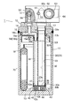
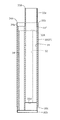
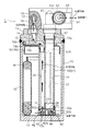
- FIG. 2 is a partially cutaway longitudinal sectional view taken along the line of arrows AC passing through O in FIG. 1.
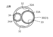
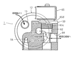
- FIG. 2 is a partially cutaway cross-sectional view taken along the line B-C along line O in FIG. 1.
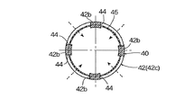
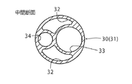
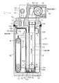
- FIG. 5 is a cross-sectional view taken along the line VV in FIG. 2.
- the longitudinal cross-sectional view which shows the state before the assembly
- tube shown by FIG. The partial notch top view which shows the refrigerant
- the partial notch top view which shows the refrigerant
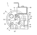
- FIG. 1 is a top view of an embodiment of a refrigerant container according to the present invention
- FIG. 2 is a partially cutaway longitudinal sectional view taken along line A--C in FIG. 1
- FIG. 3 passes through O in FIG.
- FIG. 6 is a partially cutaway cross-sectional view taken along the line B-C.
- the refrigerant container 1 of the illustrated embodiment is used in, for example, a heat pump system constituting a car air conditioner for an electric vehicle, and has a bottomed cylindrical tank 10 made of metal such as stainless steel or aluminum alloy.
- the upper surface opening is hermetically closed by the same metal lid member 12.
- the refrigerant container 1 of this embodiment is installed vertically as shown in the figure, that is, with the lid member 12 on the upper (top) side and the bottom 13 of the tank 10 on the lower (ground) side.
- the lid member 12 is provided with a gas-liquid inlet 15 and a stepped large-diameter gas-phase outlet 17 that pass through the lid member 12 and open upward and downward, and have a relatively small diameter.
- the liquid phase outlet 16 is provided.
- the liquid-phase outlet 16 is accompanied by a channel portion 16a that is laid down at the bottom and is L-shaped and open at one end (lower end). The other end of the passage portion 16a (the other opening in the horizontal direction) is closed with a plug 16b.
- connection adapter 50 On the upper side of the lid member 12 so as to cover a portion other than the gas-liquid inlet 15, a connection adapter 50 having a rectangular shape in plan view and a rectangular shape in front view lacking a portion covering the gas-liquid inlet 15 is provided with bolts 51, 51. It is attached in an airtight manner.
- This connection adapter 50 functions as a valve body of an on-off valve 65 described later.
- the lid member 12 is provided with a female thread portion 52 for screwing the flange portion of the inflow conduit, and the connection adapter 50 is provided with a flange portion of the inflow and outflow conduits to be described later.
- Female screw portions 53, 53 and the like for screwing are provided (the internal structure of the connection adapter 50 will be described in detail later).
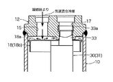
- a gas-liquid separator 18 having a slightly smaller diameter than the inner diameter of the tank 10 and having an inverted thin bowl shape is in contact with the lower surface of the lid member 12. Is distributed.
- the upper end of the gas-liquid outflow pipe 30 is connected to the lower part of the gas-phase outlet 17 in the lid member 12.
- the gas-liquid outflow pipe 30 is manufactured by extrusion molding using, for example, an aluminum alloy or the like as a raw material, and in addition to FIG. 2, refer to FIGS. 5 and 6A to D showing the state before the assembly to the tank 10.
- the outer tube portion 31 has a circular cross-sectional outer shape, and the inside of the outer tube portion 31 opens below the gas-liquid separator 18 so that the upper end thereof opens and the gas-phase refrigerant in the upper portion of the tank 10.
- the refrigerant is divided into a relatively small diameter liquid phase inner pipe portion 34 for guiding the refrigerant to the liquid phase outlet 16.
- the height positions of the upper end surfaces 32A, 33A, and 34A of the lower feed flow path section 32, the upper feed inner pipe section 33, and the liquid phase inner pipe section 34 are the upper feed inner pipe section 33 and the liquid phase inner pipe. It becomes low in order of the part 34 and the lower sending flow path part 32. Further, at the height position near the gas-liquid separator 18 in the upper feed pipe section 33, there is a pressure equalizing hole 33f for preventing liquid back to the compressor side when the system is stopped (ON ⁇ OFF). Is provided.
- the upper end portion 33 a of the upper feed inner pipe portion 33 in the gas-liquid outflow pipe 30 is thin, and the thin upper end portion 33 a is connected to the through hole 19 provided in the gas-liquid separator 18 and the gas-phase outlet 17.
- the pipe is passed through the lower part and the upper part is expanded and fixed to an annular recess 17 a formed in the middle part of the gas-phase outlet 17.
- the gas-liquid separator 18 is sandwiched and locked between the stepped portion 33b (and the upper end of the liquid phase inner pipe portion 34) provided at the lower end portion of the thin upper end portion 33a and the lower end surface of the lid member 12.
- the gas-liquid outflow pipe 30 is fixedly held by the lid member 12.
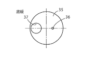
- the lowermost end portion of the gas-liquid outflow pipe 30 is a caulking thin portion 30b for caulking and fixing the bottom plate 35, and above the caulking thin portion 30b, in a case 42 of a strainer 40 described later.
- a lower end thin portion 30a that is slightly thicker than the caulking thin portion 30b and is fitted and fixed to the upper portion 42a with an inner circumferential step by press fitting or the like is provided.
- a notch opening 33d is formed at the lower end portion of the wall portion that partitions the upper feed pipe portion 33 and the left and right (front and rear in the drawing) pair of lower feed flow path portions 32, 32 for communicating them. .
- the bottom plate 35 that is caulked and fixed to the lower end (the caulking thin portion 30 b) of the gas-liquid outflow pipe 30 is oiled on the center line of the upper feed inner pipe 33 or in the region inside the upper feed inner pipe 33.
- a return hole 36 is provided, and a liquid suction port 37 having substantially the same diameter as the liquid phase inner pipe portion 34 is provided at a portion facing the liquid phase inner pipe portion 34.
- the hole diameter of the oil return hole 36 is set to about 1 mm, for example.
- a thin outer fitting portion 34 a is provided at the upper end portion of the liquid phase inner pipe portion 34
- a thin inner fitting portion 16 c is provided at the lower end portion of the passage portion 16 a of the liquid phase outlet 16 in the lid member 12.
- the thin outer fitting portion 34a and the thin inner fitting portion 16c are fitted together, and an O-ring 38 is interposed between the lower end step portion of the thin outer fitting portion 34a and the upper end step portion of the thin inner fitting portion 16c. ing.
- the liquid phase inner pipe portion 34 and the liquid phase outlet 16 are hermetically connected.
- the gas-liquid separator 18 is made of a metal such as stainless steel or aluminum alloy, and covers the upper end opening of the lower flow path portion 32 in the gas-liquid outflow pipe 30. ) Is fixedly arranged below the predetermined distance from the lower end surface.
- the gas-liquid separator 18 is provided with a through hole 19 through which an upper feed inner pipe portion 33 of the gas-liquid outflow pipe 30 and a lower side portion of the passage portion 16a of the liquid phase outlet 16 are inserted, and a lower feed passage. It has a disk-shaped ceiling portion 18a that is opposed to a predetermined distance above the upper end opening of the portion 32, and a cylindrical peripheral wall portion 18b that continues downward from the outer periphery of the ceiling portion 18a.
- a strainer 40 is provided at the lower end of the gas-liquid outflow pipe 30.
- the strainer 40 is placed and fixed on the bottom 13 of the tank 10, and as can be understood with reference to FIG. 4, the bottomed cylindrical case 42 made of synthetic resin and the case 42 It consists of a cylindrical mesh filter 45 integrated by insert molding or the like.
- the mesh filter 45 is made of, for example, a wire mesh or a mesh material made of synthetic resin.
- a case 42 of the strainer 40 is erected at equal angular intervals on an inner circumferential stepped upper portion 42a in which the lower end portion of the gas-liquid outflow pipe 30 is fitted and fixed, a bottom plate portion 42c, and an outer periphery of the bottom plate portion 42c. And four columnar portions 42b connecting the upper portions 42a.
- An annular connecting band part is provided on the outer periphery of the bottom plate part 42c, and upper and lower ends of the mesh filter 45 are fixed to the connecting band part and the lower side of the upper part 42a. That is, four windows 44 having a rectangular shape in side view are defined between the four columnar portions 42b, and a mesh filter 45 is stretched on each window 44 portion.
- the mesh filter 45 may be integrated by insert molding when the case 42 is molded. Further, the four columnar portions 42b are provided with gradients for die cutting, but the radial widths of the four columnar portions 42b are substantially equal. Further, the method of providing the mesh filter 45 in the case 42 is not limited to the above.
- a bag 70 containing a desiccant M having a predetermined height is placed on the bottom 13 along the inner periphery of the tank 10 in order to absorb and remove moisture in the refrigerant. Be present.
- the bag 70 is made of a cloth-like body such as felt having air permeability, water permeability and required shape retention, and is filled with a granular desiccant M in the bag 70.
- FIGS. 7A, 7 B, 8 A, and B in addition to FIGS. 1 and 2 on the left end of the front side of the connection adapter 50 mounted on the lid member 12 of the tank 10 having the above-described internal configuration.
- a vertical hole outlet 56 formed of a vertical hole connected to the liquid phase outlet 16 and a horizontal hole outlet 57 formed of a horizontal hole connected to the upper end of the vertical hole outlet 56 are provided.
- the side hole outlet 57 is open to the front side of the connection adapter 50, and a conduit for guiding the liquid refrigerant to the expansion valve is connected to the side hole outlet 57.
- a relatively large-diameter vertical hole outlet 61 composed of a vertical hole connected to the gas-phase outlet 17 is provided in the vicinity of the central portion of the connection adapter 50 as viewed from the front, and an end on the front side of the vertical hole outlet 61 is provided.
- a valve body sliding hole 62 having a relatively large diameter and a lateral hole opened on the rear surface side is provided so that the portions overlap.
- a portion of the front side end portion of the valve body sliding hole 62 that overlaps the vertical hole outlet 61 is a notch opening, and the vertical hole outlet 61 and the valve body sliding hole 62 communicate with each other through the notch opening. It has become.
- one end side opens to the bottom surface (front side surface) of the valve body sliding hole 62 on the front side coaxial with the valve body sliding hole 62 in the connection adapter 50, and the other end side is connected.
- a gas-phase circulation port 63 comprising a stepped horizontal hole having a smaller diameter than the valve body sliding hole 62 opened in front of the adapter 50 is provided.
- the gas-phase circulation port 63 is connected to a conduit for guiding the gas-phase refrigerant from the evaporator to the compressor suction side.
- connection adapter 50 is provided with a lateral hole outlet 64 formed of a relatively large diameter lateral hole having one end opened to the gas-phase flow port 63 and the other end opened to the right side surface.
- the horizontal hole outlet 64 is connected to a conduit for guiding the gas-phase refrigerant to the compressor suction side.
- an opening / closing valve 65 is mounted and fixed sideways with a lid-like material 65d closing the rear surface side opening of the valve body sliding hole 62 interposed therebetween.
- the on-off valve 65 is an electromagnetic type here, and its structure is well known, and is a coil, a suction element, a plunger 65b, and a thick disk-like valve attached and fixed to the tip of the plunger 65b.
- a valve closing spring composed of a compression coil spring that urges the body 65c and the plunger 65b in a direction (valve closing direction) away from the attractor is provided.
- the valve body 65c is slidably inserted into the valve body sliding hole 62, and when the valve is closed (when the power is OFF), as shown in FIGS. 7A and 7B, the bottom surface ( Gas-phase refrigerant from the vertical hole outlet 61 to the horizontal hole outlet 64 through the valve body sliding hole 62 and the gas-phase outlet 63. Shut off the outlet channel.
- valve body 65c moves away from the bottom surface (valve seat) of the valve body sliding hole 62 and One end opening is opened, and the gas-phase refrigerant flows from the vertical hole outlet 61 to the horizontal hole outlet 64 through the valve body sliding hole 62 and the gas-phase circulation port 63.
- the refrigerant in a gas-liquid mixed state introduced into the tank 10 from the condenser through the gas-liquid inlet 15 is, as shown in FIG.
- the liquid phase refrigerant (including oil) flows down along the inner peripheral surface of the tank 10 and is separated into a liquid phase refrigerant and a gas phase refrigerant.
- the gas-phase refrigerant is guided to the upper space of the tank 10.
- the on-off valve 65 is closed (power OFF), and the one end opening of the gas-phase circulation port 63 is closed by the valve body 65c.
- Space ⁇ Lower feed channel portion 32 ⁇ Notch opening 33d ⁇ Upper inner pipe portion 33 ⁇ Gas flow outlet 17 ⁇ Vertical hole outlet 61 ⁇ Valve sliding hole 62 ⁇ Horizontal hole flow through the gas phase flow port 63
- the gas-phase refrigerant outlet flow path to the outlet 64 is blocked, and instead, the gas-phase refrigerant from the evaporator is guided to the compressor suction side through the gas-phase circulation port 63 ⁇ the side hole outlet 64.
- the liquid-phase refrigerant accumulated in the lower space of the tank 10 is strained by the strainer 40 (the mesh filter 45) ⁇ the liquid suction port 37 of the bottom plate 35 ⁇ It is led to the expansion valve via the liquid phase inner pipe section 34 ⁇ the liquid phase outlet 16 ⁇ the vertical hole outlet 56 ⁇ the lateral hole outlet 57.
- the refrigerant container 1 of the present embodiment functions as a receiver (receiver dryer).
- the on-off valve 65 is opened (power ON), and the valve body 65c is separated from the bottom surface (valve seat) of the valve body sliding hole 62. Since one end opening of the gas-phase circulation port 63 is opened, the gas-phase refrigerant separated by the gas-liquid separator 18 is transferred from the upper space of the tank 10 to the lower feed channel 32 ⁇ the notch opening 33 d ⁇ the upper feed pipe. 33 ⁇ Gas phase outlet 17 ⁇ Vertical hole outlet 61 ⁇ Valve sliding hole 62 ⁇ Gas flow outlet 63 ⁇ Horizontal hole outlet 64 is directly sucked into the compressor suction side and circulated.
- the oil that accumulates in the lower space of the tank 10 together with the liquid phase refrigerant moves to the bottom 13 side of the tank 10 due to the difference in specific gravity and properties with the liquid phase refrigerant, and the lower flow path of the gas-liquid outflow pipe 30 Part 32 ⁇ Suction by the gas-phase refrigerant sucked into the compressor suction side via the upper feed inner pipe 33, the mesh filter 45 of the strainer 40 ⁇ the oil return hole 36 of the bottom plate 35 ⁇ the upper feed inner pipe 33 It is returned to the compressor suction side together with the gas-phase refrigerant and circulated. When passing through the mesh filter 45, foreign matter such as sludge is captured, and the foreign matter is removed from the circulating refrigerant (including oil).
- the refrigerant container 1 of the present embodiment functions as an accumulator.
- the refrigerant container 1 of the present embodiment has both the receiver function and the accumulator function, while the tank part (tank 10), the inlet part (gas-liquid inlet 15), the gas-liquid separation part ( Since the gas-liquid separator 18), the outflow pipe part (gas-liquid outflow pipe 30), and the strainer part (strainer 40) are shared, a rational structure with a small number of parts can be obtained.
- the space occupied by the entire system can be reduced, the number of parts can be reduced, and cost reduction and downsizing can be effectively achieved.
- an opening / closing valve 65 is attached to the refrigerant container 1 so that the state of functioning as a receiver and the state of functioning as an accumulator can be switched by opening / closing (ON-OFF) of the opening / closing valve 65 according to the operating state of the system. Therefore, the piping system of the system can be simplified as compared with, for example, a case where an on-off valve is provided outside.
- the gas-phase refrigerant outlet passage to the gas-phase outlet 17 ⁇ the vertical hole outlet 61 ⁇ the valve body sliding hole 62 ⁇ the gas-phase circulation port 63 ⁇ the horizontal hole outlet 64 is opened and closed.
- an opening / closing valve for opening and closing the liquid phase refrigerant outlet flow path from the liquid phase outlet 16 to the vertical hole outlet 56 to the horizontal hole outlet 57 is provided,
- the on-off valve may be opened / closed in a reverse manner to the gas-phase refrigerant side, and the on-off valves for gas phase and liquid phase may be combined into a four-way valve.
Landscapes
- Engineering & Computer Science (AREA)
- Physics & Mathematics (AREA)
- Mechanical Engineering (AREA)
- Thermal Sciences (AREA)
- Chemical & Material Sciences (AREA)
- Analytical Chemistry (AREA)
- Power Engineering (AREA)
- General Engineering & Computer Science (AREA)
- Air-Conditioning For Vehicles (AREA)
- Compressor (AREA)
Priority Applications (4)
| Application Number | Priority Date | Filing Date | Title |
|---|---|---|---|
| KR1020187025742A KR102345280B1 (ko) | 2016-12-27 | 2017-10-17 | 냉매 용기 |
| US16/314,181 US10926608B2 (en) | 2016-12-27 | 2017-10-17 | Refrigerant container |
| CN201780023986.6A CN109073297B (zh) | 2016-12-27 | 2017-10-17 | 制冷剂容器 |
| EP17885752.0A EP3495755B1 (en) | 2016-12-27 | 2017-10-17 | Refrigerant container |
Applications Claiming Priority (2)
| Application Number | Priority Date | Filing Date | Title |
|---|---|---|---|
| JP2016-252839 | 2016-12-27 | ||
| JP2016252839A JP6539640B2 (ja) | 2016-12-27 | 2016-12-27 | 冷媒容器 |
Publications (1)
| Publication Number | Publication Date |
|---|---|
| WO2018123215A1 true WO2018123215A1 (ja) | 2018-07-05 |
Family
ID=62707258
Family Applications (1)
| Application Number | Title | Priority Date | Filing Date |
|---|---|---|---|
| PCT/JP2017/037448 WO2018123215A1 (ja) | 2016-12-27 | 2017-10-17 | 冷媒容器 |
Country Status (6)
Cited By (1)
| Publication number | Priority date | Publication date | Assignee | Title |
|---|---|---|---|---|
| EP3936793A4 (en) * | 2019-03-05 | 2022-11-16 | Fujikoki Corporation | REFRIGERANT TANK |
Families Citing this family (4)
| Publication number | Priority date | Publication date | Assignee | Title |
|---|---|---|---|---|
| JP2018532091A (ja) | 2015-08-11 | 2018-11-01 | トレイン インターナショナル インク | 冷媒の回収および再利用 |
| DE102021204470A1 (de) * | 2020-05-05 | 2021-11-11 | Mahle International Gmbh | Kältemittelsystem und Kraftfahrzeug |
| CN113970001A (zh) * | 2020-07-25 | 2022-01-25 | 浙江三花汽车零部件有限公司 | 集成组件 |
| JP7650499B2 (ja) * | 2021-07-13 | 2025-03-25 | 株式会社不二工機 | 弁装置 |
Citations (8)
| Publication number | Priority date | Publication date | Assignee | Title |
|---|---|---|---|---|
| JPH02169970A (ja) * | 1988-12-22 | 1990-06-29 | Nippondenso Co Ltd | 受液器 |
| JPH0968371A (ja) * | 1995-08-31 | 1997-03-11 | Nippon Soken Inc | 気液分離器 |
| JPH11159920A (ja) * | 1997-11-27 | 1999-06-15 | Denso Corp | 冷凍サイクル装置 |
| EP1132696A1 (de) * | 2000-03-08 | 2001-09-12 | Hansa Metallwerke Ag | Akkumulator für eine nach dem Orifice-Prinzip arbeitende Klimaanlage, insbesondere Fahrzeugklimaanlage |
| JP2009174836A (ja) * | 2008-01-23 | 2009-08-06 | Nichirei Kogyo Kk | 気液分離装置および気液分離装置を備えた冷凍装置。 |
| JP2012093051A (ja) * | 2010-10-28 | 2012-05-17 | Fuji Koki Corp | ヒートポンプ用気液分離器及びインジェクション式ヒートポンプシステム |
| WO2013190769A1 (ja) * | 2012-06-22 | 2013-12-27 | 株式会社デンソー | 減圧装置および冷凍サイクル装置 |
| JP2014095491A (ja) * | 2012-11-08 | 2014-05-22 | Fuji Koki Corp | アキュムレータ |
Family Cites Families (16)
| Publication number | Priority date | Publication date | Assignee | Title |
|---|---|---|---|---|
| JPH0989420A (ja) * | 1995-09-27 | 1997-04-04 | Fuji Koki:Kk | 膨張弁付レシーバタンク |
| US5996360A (en) | 1997-11-27 | 1999-12-07 | Denso Corporation | Refrigerant cycle system |
| JP2002130874A (ja) * | 2000-10-19 | 2002-05-09 | Denso Corp | 冷凍サイクル装置 |
| US6523365B2 (en) * | 2000-12-29 | 2003-02-25 | Visteon Global Technologies, Inc. | Accumulator with internal heat exchanger |
| US6615608B1 (en) * | 2002-06-26 | 2003-09-09 | Delphi Technologies, Inc. | Multi-function receiver |
| KR100882479B1 (ko) * | 2004-10-07 | 2009-02-06 | 엘지전자 주식회사 | 감온식 수위감지장치 및 이를 구비한 유체탱크 |
| WO2006065186A1 (en) * | 2004-12-16 | 2006-06-22 | Volvo Lastvagnar Ab | Improved air conditioning system |
| CN2781296Y (zh) * | 2005-03-27 | 2006-05-17 | 烟台欧森纳地源空调有限公司 | 三合一制冷装置 |
| CN100501279C (zh) * | 2006-03-04 | 2009-06-17 | 苏权兴 | 冷媒回路中用于过滤、分离、贮存冷媒的装置 |
| KR101126832B1 (ko) * | 2009-06-12 | 2012-03-23 | 진금수 | 냉동 사이클용 수액기겸 액분리기 및 그 제조방법 |
| CN201724482U (zh) * | 2010-05-12 | 2011-01-26 | 珠海格力电器股份有限公司 | 制冷剂汽液分离及储液一体化装置及使用该装置的空调系统 |
| JP2012136147A (ja) | 2010-12-27 | 2012-07-19 | Tgk Co Ltd | 車両用冷暖房装置 |
| KR101474819B1 (ko) * | 2011-11-23 | 2014-12-22 | 한라비스테온공조 주식회사 | 차량용 히트 펌프 시스템 |
| JP2013184596A (ja) | 2012-03-08 | 2013-09-19 | Denso Corp | 車両空調用、及び、自動車構成部品温度調整用冷凍サイクル装置 |
| CN104718382B (zh) * | 2012-10-12 | 2017-11-03 | 冷王公司 | 储液器和接纳器的组合式箱体 |
| JP2015001367A (ja) * | 2013-06-18 | 2015-01-05 | 三菱電機株式会社 | 気液分離器とそれを搭載した空気調和装置 |
-
2016
- 2016-12-27 JP JP2016252839A patent/JP6539640B2/ja active Active
-
2017
- 2017-10-17 US US16/314,181 patent/US10926608B2/en active Active
- 2017-10-17 KR KR1020187025742A patent/KR102345280B1/ko active Active
- 2017-10-17 EP EP17885752.0A patent/EP3495755B1/en active Active
- 2017-10-17 CN CN201780023986.6A patent/CN109073297B/zh active Active
- 2017-10-17 WO PCT/JP2017/037448 patent/WO2018123215A1/ja unknown
Patent Citations (8)
| Publication number | Priority date | Publication date | Assignee | Title |
|---|---|---|---|---|
| JPH02169970A (ja) * | 1988-12-22 | 1990-06-29 | Nippondenso Co Ltd | 受液器 |
| JPH0968371A (ja) * | 1995-08-31 | 1997-03-11 | Nippon Soken Inc | 気液分離器 |
| JPH11159920A (ja) * | 1997-11-27 | 1999-06-15 | Denso Corp | 冷凍サイクル装置 |
| EP1132696A1 (de) * | 2000-03-08 | 2001-09-12 | Hansa Metallwerke Ag | Akkumulator für eine nach dem Orifice-Prinzip arbeitende Klimaanlage, insbesondere Fahrzeugklimaanlage |
| JP2009174836A (ja) * | 2008-01-23 | 2009-08-06 | Nichirei Kogyo Kk | 気液分離装置および気液分離装置を備えた冷凍装置。 |
| JP2012093051A (ja) * | 2010-10-28 | 2012-05-17 | Fuji Koki Corp | ヒートポンプ用気液分離器及びインジェクション式ヒートポンプシステム |
| WO2013190769A1 (ja) * | 2012-06-22 | 2013-12-27 | 株式会社デンソー | 減圧装置および冷凍サイクル装置 |
| JP2014095491A (ja) * | 2012-11-08 | 2014-05-22 | Fuji Koki Corp | アキュムレータ |
Cited By (1)
| Publication number | Priority date | Publication date | Assignee | Title |
|---|---|---|---|---|
| EP3936793A4 (en) * | 2019-03-05 | 2022-11-16 | Fujikoki Corporation | REFRIGERANT TANK |
Also Published As
| Publication number | Publication date |
|---|---|
| CN109073297B (zh) | 2021-06-22 |
| EP3495755B1 (en) | 2021-03-17 |
| JP6539640B2 (ja) | 2019-07-03 |
| EP3495755A1 (en) | 2019-06-12 |
| US10926608B2 (en) | 2021-02-23 |
| JP2018105552A (ja) | 2018-07-05 |
| KR102345280B1 (ko) | 2021-12-31 |
| US20190225055A1 (en) | 2019-07-25 |
| CN109073297A (zh) | 2018-12-21 |
| EP3495755A4 (en) | 2020-01-01 |
| KR20190102136A (ko) | 2019-09-03 |
Similar Documents
| Publication | Publication Date | Title |
|---|---|---|
| WO2018123215A1 (ja) | 冷媒容器 | |
| US9428043B2 (en) | Liquid vapor separator drain valve | |
| WO2018123216A1 (ja) | 冷媒容器 | |
| CN109964090B (zh) | 储液器 | |
| KR20130113364A (ko) | 팽창밸브 | |
| KR20100087105A (ko) | 팽창밸브 | |
| JP2003130499A (ja) | 膨張弁 | |
| WO2020170627A1 (ja) | アキュームレータ | |
| CN106352620B (zh) | 储液器 | |
| JP6823865B2 (ja) | アキュームレータ | |
| US20210180843A1 (en) | Receiver/drier for a refrigerant fluid circuit equipping a vehicle, in particular a motor vehicle | |
| WO2019107011A1 (ja) | アキュームレータ | |
| JP6767099B2 (ja) | アキュームレータ | |
| US6449978B2 (en) | Air-conditioning refrigerant receiver | |
| JP2013181495A (ja) | 気液分離装置 | |
| JP2011185597A (ja) | 遠心分離装置 | |
| EP2963364A1 (en) | Accumulator for an air conditioning system |
Legal Events
| Date | Code | Title | Description |
|---|---|---|---|
| ENP | Entry into the national phase |
Ref document number: 20187025742 Country of ref document: KR Kind code of ref document: A |
|
| 121 | Ep: the epo has been informed by wipo that ep was designated in this application |
Ref document number: 17885752 Country of ref document: EP Kind code of ref document: A1 |
|
| ENP | Entry into the national phase |
Ref document number: 2017885752 Country of ref document: EP Effective date: 20190307 |
|
| NENP | Non-entry into the national phase |
Ref country code: DE |