WO2018117137A1 - 複合ケーブル - Google Patents
複合ケーブル Download PDFInfo
- Publication number
- WO2018117137A1 WO2018117137A1 PCT/JP2017/045654 JP2017045654W WO2018117137A1 WO 2018117137 A1 WO2018117137 A1 WO 2018117137A1 JP 2017045654 W JP2017045654 W JP 2017045654W WO 2018117137 A1 WO2018117137 A1 WO 2018117137A1
- Authority
- WO
- WIPO (PCT)
- Prior art keywords
- optical fiber
- composite cable
- coated
- fiber unit
- conductor
- Prior art date
- Legal status (The legal status is an assumption and is not a legal conclusion. Google has not performed a legal analysis and makes no representation as to the accuracy of the status listed.)
- Ceased
Links
Images





Classifications
-
- G—PHYSICS
- G02—OPTICS
- G02B—OPTICAL ELEMENTS, SYSTEMS OR APPARATUS
- G02B6/00—Light guides; Structural details of arrangements comprising light guides and other optical elements, e.g. couplings
- G02B6/44—Mechanical structures for providing tensile strength and external protection for fibres, e.g. optical transmission cables
-
- H—ELECTRICITY
- H01—ELECTRIC ELEMENTS
- H01B—CABLES; CONDUCTORS; INSULATORS; SELECTION OF MATERIALS FOR THEIR CONDUCTIVE, INSULATING OR DIELECTRIC PROPERTIES
- H01B11/00—Communication cables or conductors
- H01B11/22—Cables including at least one electrical conductor together with optical fibres
-
- H—ELECTRICITY
- H01—ELECTRIC ELEMENTS
- H01B—CABLES; CONDUCTORS; INSULATORS; SELECTION OF MATERIALS FOR THEIR CONDUCTIVE, INSULATING OR DIELECTRIC PROPERTIES
- H01B7/00—Insulated conductors or cables characterised by their form
Definitions
- the present invention relates to a composite cable composed of a plurality of optical fiber core wires and coated conductors.
- optical / metal composite cables with metal wires mounted for communication and power supply.
- the metal wire used for this composite cable a twisted pair wire obtained by twisting two coated conductor wires each having an insulating coating applied to a copper wire or a quad twisted wire obtained by twisting four wires is used.
- a composite cable for example, an optical composite cable formed by twisting two pairs of twisted coated conductors and an optical fiber to form a composite cord, and further twisting a plurality of composite cords Is described (Patent Document 1).
- a slot-type optical fiber cable that uses a spacer and accommodates a plurality of coated conductors and optical fibers in each groove (Patent Document 2).
- the composite cable of Patent Document 2 has a structure in which the coated conductor and the optical fiber are made independent of each other in order to reduce the external pressure on the optical fiber.
- slotless cables that do not use grooved spacers (slots) have been applied for the purpose of reducing the diameter and weight of composite cables.
- the optical fiber may be subjected to a large external force by the coated conductor when the composite cable is bent. Therefore, there is a need for a method for suppressing an increase in loss due to an external pressure applied to an optical fiber even in a slotless cable in which a coated conductor and an optical fiber are combined.
- the present invention has been made in view of such problems, and provides a composite cable that is a slotless cable in which a coated conductor and an optical fiber are mounted, and that can reduce external pressure on the optical fiber. For the purpose.
- the present invention relates to a plurality of optical fiber units in a cross section perpendicular to the longitudinal direction of the optical fiber unit, a coated conductor, and the optical fiber unit.
- a composite cable comprising a pair of tension members provided at positions facing each other and a jacket provided so as to cover the optical fiber unit and the tension member, and an arbitrary position in the longitudinal direction of the composite cable
- the composite cable is characterized in that, in a cross section perpendicular to the longitudinal direction of the composite cable, a center position of the covered conductor is located in a region surrounded by the pair of tension members.
- the present invention also provides an optical fiber unit comprising a plurality of optical fiber core wires, a coated conducting wire, and one tension provided outside the plurality of optical fiber units in a cross section perpendicular to the longitudinal direction of the optical fiber unit.
- a composite cable comprising a member and a jacket provided so as to cover the optical fiber unit and the tension member, and is perpendicular to the longitudinal direction of the composite cable at an arbitrary position in the longitudinal direction of the composite cable
- the coated conductor may be a composite cable characterized by being positioned on a straight line passing through the center of the tension member and the composite cable.
- the coated conductor may be disposed at substantially the center of the composite cable.
- the coated conductor may be disposed on the outer periphery of the plurality of optical fiber units.
- the softening temperature of the coating resin of the coated conductor may be higher than the softening temperature of the resin of the jacket.
- a plurality of the coated conductors may be twisted together, and the twisting direction of the optical fiber unit and the twisting direction of the coated conductors may be opposite to each other.
- a plurality of the coated conductors are twisted together, and the twisted pitch of the coated conductors may be smaller than the twisted pitch of the optical fiber unit.
- a plurality of the coated conductors may be twisted together, and a tape-shaped member may be vertically wound around the outer periphery of the plurality of the coated conductors.
- the center position of the coated conductor is located in the region surrounded by the pair of tension members, it is possible to suppress the generation of external pressure on the optical fiber core by the coated conductor.
- the coated conductor when the coated conductor is disposed at a position deviated from the straight line of the pair of tension members, the composite cable is bent with the line connecting the pair of tension members as a neutral axis due to expansion and contraction of the coated conductor. Accordingly, the coated conductor and the optical fiber core are also bent, and the coated conductor applies an external pressure to the optical fiber, which causes an increase in the loss of the optical fiber.
- the expanding and contracting direction is the axial direction of the composite cable. Therefore, it is possible to reduce the external pressure applied to the optical fiber by the coated conductor.
- the coated conductor since the composite cable has a pair of tension members, the bending direction of the composite cable is restricted. At this time, if the coated conductor is arranged on the straight line of the pair of tension members, the coated conductor is located on the neutral axis of the composite cable bending, so that it is not easily affected by bending, and even if the composite cable is bent, the coated conductor Does not apply external pressure to the optical fiber side.
- the coated conductor is arranged at the approximate center of the composite cable, the manufacturability is good.
- the coated conductors are arranged on the outer periphery of the plurality of optical fiber units, for example, the coated conductors can be arranged at two positions between the tension member and the optical fiber unit.
- the softening temperature of the coating resin of the coated conductor is higher than the softening temperature of the resin of the jacket, the coating of the coated conductor is softened at the time of coating, and the conductors are connected to each other, or the coated conductor is fused to the surrounding Can be suppressed.
- the twisting direction of the coated fiber leads and the twisted direction of the coated conductors are opposite to each other.
- the fiber can be prevented from entering.
- the optical fiber enters the twist gap of the coated conductor by making the twisted pitch of the coated conductors smaller than the twist pitch of the optical fiber unit. This can be suppressed.
- a tape-like member is vertically wound around the outer periphery of the plurality of coated conductors to prevent the optical fiber from entering the twist gap of the coated conductors. be able to.
- a composite cable that is a slotless cable in which a coated conductor and an optical fiber are mounted, and that can reduce the external pressure applied to the optical fiber.
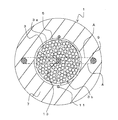
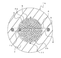
- FIG. Sectional drawing which shows the composite cable 1. The figure which shows the twisted state of the optical fiber unit bundle 3b. The figure which shows the twisted state of the some covered conducting wire 13. The figure which shows the other twist state of the some coating
- FIG. 1 is a cross-sectional view perpendicular to the longitudinal direction of the composite cable 1.
- the composite cable 1 is a slotless type that does not use a slot, and includes a plurality of optical fiber core wires 3, a presser winding member 5, a jacket 7, a tension member 9, a tearing cord 11, a covered conductor 13, and the like.
- an assembly in which a plurality of optical fiber cores 3 are bundled with a bundle material or the like is referred to as an optical fiber unit 3a, and a bundle of the plurality of optical fiber units 3a is referred to as an optical fiber unit bundle 3b.
- the optical fiber core 3 may be a single core or a tape core.
- the optical fiber core wire 3 When the optical fiber core wire 3 is a tape core wire, it may be an intermittent optical fiber tape core wire that is intermittently bonded to the longitudinal direction.
- the number of optical fiber cores constituting the optical fiber unit 3a is not particularly limited, and the number of optical fiber units 3a in the optical fiber unit bundle 3b is not particularly limited.
- a holding member 5 is provided on the outer periphery of the optical fiber unit bundle 3b.
- the presser winding member 5 is disposed so as to collectively cover the optical fiber unit bundle 3b by vertical additional winding. That is, the longitudinal winding of the optical fiber unit bundle 3b is vertically attached so that the longitudinal direction of the presser winding member 5 is substantially coincident with the axial direction of the composite cable 1 and the width direction of the presser winding member 5 is the circumferential direction of the composite cable 1. Is done.
- a jacket 7 is provided on the outer periphery of the presser winding member 5.
- the jacket 7 is a layer for covering and protecting the composite cable 1.
- a pair of tension members 9 are provided at positions facing the optical fiber unit bundle 3b.
- a tear string 11 is provided in a direction substantially orthogonal to the opposing direction of the tension member 9 so as to face each other with the presser winding member 5 interposed therebetween.
- the tension member 9 and the tear string 11 are embedded in the outer jacket 7. That is, the jacket 7 is provided so as to cover the optical fiber unit bundle 3 b, the tension member 9, and the tear string 11.
- a plurality of covered conductors 13 are arranged twisted together. That is, at an arbitrary position in the longitudinal direction of the composite cable 1, the center position of the covered conductor 13 is within a region surrounded by the pair of tension members 9 in a cross section perpendicular to the longitudinal direction of the composite cable 1 (a pair of tension members When 9 is viewed in the horizontal direction, each tension member 9 is located in a region surrounded by a line A connecting the upper ends and lower ends of each tension member 9.
- the center of the coated conducting wire 13 is a twisted center (center of a circumscribed circle) in which a plurality of coated conducting wires 13 are twisted together.
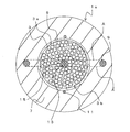
- FIG. 2 is a diagram showing a state in which the center position of the covered conducting wire 13 is located in a region surrounded by the pair of tension members 9 and a part of the covered conducting wire 13 protrudes outside the region.
- the covered conductor 13 may protrude from the region in a part or the entire length of the composite cable 1 in the longitudinal direction.
- the diameter of the circumscribed circle of the twisted covered conductor 13 is larger than the outer diameter of the tension member 9, the region where the center position of the covered conductor 13 is surrounded by the pair of tension members 9 is naturally. If it is located inside, a part of the covered conductor 13 may protrude from the region over the entire length.
- Fig. 3a is a conceptual diagram showing a twisted state of the optical fiber unit bundle 3b
- Fig. 3b is a conceptual diagram showing a twisted state of the coated conducting wire 13 arranged inside the optical fiber unit bundle 3b.
- the optical fiber unit bundle 3b is configured by twisting a plurality of optical fiber units 3a.
- the plurality of covered conductors 13 are twisted together.
- the twisting pitch of the optical fiber unit 3a be P1.
- the twisting pitch of the covering conducting wire 13 be P2.
- the twisting direction of the optical fiber unit 3a and the twisting direction of the coated conductor 13 are the same direction.
- the twisting pitch P2 of the coated conductor 13 is smaller than the twisting pitch P1 of the optical fiber unit 3a.
- the value of P2 / P1 is preferably 0.5 or less.
- the twisting pitch of the coated conducting wire 13 smaller than the twisting pitch of the optical fiber unit 3 a, for example, the optical fiber core wire 3 around the coated conducting wire 13 is in the valley of the twisting of the coated conducting wire 13. Intrusion can be prevented. Therefore, it is possible to suppress the external pressure from being applied to the optical fiber core wire 3 by the coated conducting wire 13.
- the twisting direction of the coated conductor 13 may be opposite to the twisting direction of the optical fiber unit 3a. Even if it does in this way, it can prevent that the optical fiber core wire 3 of the circumference
- the composite cable 1a is manufactured as follows, for example. First, the coated conducting wires 13 are twisted together, and a plurality of optical fiber units 3a formed in advance are sent to the outer periphery while twisting them, and the press-winding member 5 is vertically wound around the outer periphery. Furthermore, the tension member 9 and the tear string 11 are sent to the outer periphery, and the outer jacket 7 is pushed out and covered to manufacture the composite cable 1a.
- the covered conductive wire 13 is disposed in a region surrounded by the pair of tension members 9. For this reason, when the coated conducting wire 13 expands and contracts due to a temperature change or the like, the coated conducting wire 13 expands and contracts with respect to the axial direction. Therefore, it is possible to reduce the influence of the difference in deformation amount between the coated conducting wire 13 and the optical fiber core wire 3 caused by the difference in thermal expansion coefficient. For this reason, the external pressure to the surrounding optical fiber core wire 3 accompanying the deformation
- the bending direction of the composite cable 1 is regulated by the arrangement of the tension member 9, but when the composite cable 1 is bent, the covered conductor 13 is also arranged near the neutral axis of the bending. For this reason, the deformation amount of the covered conducting wire 13 when the composite cable 1 is bent is small. Accordingly, it is possible to reduce the influence of the difference in deformation amount between the coated conductor 13 and the optical fiber core 3 due to the difference in elastic modulus. As a result, the composite cable 1 can be easily bent, and even if the composite cable 1 is bent, it is possible to suppress the optical fiber core wire 3 from being subjected to external pressure by the coated conductor 13.
- the productivity of the composite cable 1 is excellent.
- FIG. 4 is a cross-sectional view of the composite cable 1a according to the second embodiment.
- components having the same functions as those of the first embodiment are denoted by the same reference numerals as those in FIG. 1, and redundant descriptions are omitted.
- the composite cable 1 a has substantially the same configuration as the composite cable 1, but differs in that a tape-like member 15 is provided on the outer periphery of the plurality of coated conductive wires 13.
- the tape-like member 15 is, for example, a resin tape.
- the plurality of coated conductors 13 are twisted together, and the tape-like member 15 is vertically wound around the outer periphery of the plurality of coated conductors 13.
- the composite cable 1 a can be obtained by twisting the optical fiber unit 3 a around the outer periphery of the tape-like member 15.
- the tape-like member 15 can prevent the coated conducting wire 13 and the optical fiber core wire 3 from coming into direct contact.
- the same effect as that of the first embodiment can be obtained. Further, since the tape-like member 15 is provided on the outer periphery of the coated conducting wire 13, the optical fiber core wire does not fit into the twisted valley of the coated conducting wire 13. For this reason, the influence of the external pressure on the optical fiber core wire 3 can be suppressed by the coated conducting wire 13.
- FIG. 5 is a cross-sectional view of the composite cable 1b according to the third embodiment.
- the composite cable 1b is substantially the same as the composite cable 1, but the arrangement of the covered conductors 13 is different.
- the coated conductor 13 is disposed not on the center of the composite cable 1b but on the outer periphery of the plurality of optical fiber units 3a. That is, the covered conducting wire 13 is disposed between the optical fiber unit bundle 3 b and the presser winding member 5. Even in this case, the tape-like member 15 may be provided on the outer periphery of the coated conducting wire 13.
- the coated conductor 13 is formed by coating an inner conductor with a coating resin.
- the softening temperature of the coating resin of the coated conductive wire 13 is higher than the softening temperature of the resin of the jacket 7.
- the same effect as that of the first embodiment can be obtained. Further, by arranging the coated conductor 13 on the outer periphery of the optical fiber unit bundle 3b, for example, even when the twisted coated conductor 13 is disposed at two places in the cross section, the coated conductor 13 is connected to each tension member 9. Can be placed inside.
- the coated conducting wire 13 since the coated conducting wire 13 is disposed on the outer periphery of the optical fiber unit bundle 3b, the coated conducting wire 13 may be made to follow the outer periphery of the optical fiber unit bundle 3b after the optical fiber unit bundle 3b is twisted. Easy. For this reason, the composite cable 1b can be manufactured easily.
- FIG. 6 is a cross-sectional view of the composite cable 1c according to the fourth embodiment.
- the composite cable 1c is substantially the same as the composite cable 1b, but the arrangement of the covered conductors 13 is different.
- the coated conductor 13 is disposed outside the holding member 5 provided on the outer periphery of the optical fiber unit bundle 3b and in a region surrounded by the pair of tension members 9. That is, in this case, the covered conducting wire 13 is embedded in the jacket 7.
- the softening temperature of the coating resin of the coated conductor 13 is higher than the softening temperature of the resin of the outer cover 7.
- the coated conductor 13 does not directly contact the optical fiber core wire 3, but the composite cable 1 c can be easily bent by arranging the coated conductor 13 between the tension members 9. . Further, when the composite cable 1c is bent, the deformation of the coated conductor 13 can be minimized. Moreover, it can suppress that bending deformation arises in the composite cable 1c by the expansion-contraction of the covering conducting wire 13 accompanying a temperature change. As a result, the external pressure accompanying the bending of the composite cable 1c to the optical fiber core wire 3 can be suppressed.
- the same effect as that of the first embodiment can be obtained.
- the coated conducting wire 13 in the region surrounded by the pair of tension members 9, it is possible to suppress external pressure from being generated on the optical fiber core wire 3 by the coated conducting wire 13.
- FIG. 7 is a cross-sectional view of the composite cable 1d according to the fifth embodiment.
- the composite cable 1d is substantially the same as the composite cable 1 or the like, except that the tension member 9 is one. That is, one tension member 9 is provided outside the plurality of optical fiber units 3a in a cross section perpendicular to the longitudinal direction of the optical fiber unit 3a.
- the covered conductor 13 is positioned on a straight line O passing through the center of the tension member 9 and the composite cable 1d in a cross section perpendicular to the longitudinal direction at an arbitrary position in the longitudinal direction of the composite cable 1d.
- the center position of the covered conducting wire 13 and the straight line O substantially coincide.
- the coated conductor 13 is shown as being disposed at substantially the center of the composite cable 1d. However, as described above, the coated conductor 13 is displaced from the center as in the composite cables 1b and 1c. It may be a position.
- the coated conductor 13 when the composite cable 1d is bent, the coated conductor 13 is arranged in the vicinity of the substantially neutral axis of the bending, so that the deformation amount of the coated conductor 13 when the composite cable 1d is bent is reduced. Can do.
- Example 1 As shown in FIG. 1, a coated conductor was disposed at the center of the composite cable. At this time, the coated conductor was not protruded from the region surrounded by the tension member.
- Example 2 compared to Example 1, as shown in FIG. 5, the coated conducting wire was disposed outside the optical fiber unit bundle.
- Example 3 is different from Example 2 in that the center of the covered conductor is disposed in a region surrounded by the tension member, but a part of the covered conductor is protruded from the region surrounded by the tension member.
- Example 4 compared to Example 1, as shown in FIG.
- the coated conductor was disposed in the vicinity of the tear string and outside the optical fiber unit bundle. That is, the covered conductor was disposed at a position protruding from the region surrounded by the tension member.
- each composite cable was wound around a mandrel having a diameter of 480 mm ⁇ by 180 °, and the loss increase at that time was measured to evaluate the cable bending characteristics. A loss of 0.1 dB or less was accepted, and a loss exceeding 0.1 dB was rejected. The results are shown in Table 1.
- Example 1 to Example 4 in which the coated conducting wire was disposed in the region surrounded by the pair of tension members all evaluations passed.
Landscapes
- Physics & Mathematics (AREA)
- General Physics & Mathematics (AREA)
- Optics & Photonics (AREA)
- Communication Cables (AREA)
Abstract
光ファイバユニット束3bの外周には、押さえ巻き部材5が設けられる。押さえ巻き部材5の外周には、外被7が設けられる。外被7は、複合ケーブル1を被覆して保護するための層である。光ファイバユニット3aの長手方向に垂直な断面において、光ファイバユニット束3bに対して対向する位置に一対のテンションメンバ9が設けられる。複合ケーブル1の略中心には、複数本の被覆導線13が互いに撚り合わせられて配置される。すなわち、複合ケーブル1の長手方向の任意の位置において、複合ケーブル1の長手方向に垂直な断面において、被覆導線13の中心位置が、一対のテンションメンバ9で囲まれた領域内に位置する。
Description
本発明は、複数の光ファイバ心線と被覆導線とからなる複合ケーブルに関するものである。
光ファイバとともに、通信や給電のためにメタル線が実装された光・メタル複合ケーブルがある。この複合ケーブルに使用されているメタル線としては、銅線に絶縁被覆が施された被覆導線を2本撚り合わせた対撚り線や4本撚り合わせたカッド撚り線が用いられる。
このような複合ケーブルとしては、例えば、2本の対撚り被覆導線と光ファイバを撚り合わせて被覆が施された複合コードを形成し、複数の複合コードをさらに撚り合わせて形成された光複合ケーブルが記載されている(特許文献1)。
また、スペーサを用い、それぞれの溝に複数の被覆導線及び光ファイバを収容したスロット型光ファイバケーブルが記載されている(特許文献2)。
しかし、特許文献1に記載された複合ケーブルは、被覆導線と光ファイバが一緒に撚られているため、温度変化や布設時に複合ケーブルが曲げられた際に、被覆導線によって光ファイバへ外圧が加わり、伝送損失の増加を引き起こす懸念がある。これは、光ファイバに用いられるガラスと被覆導線の銅の温度変化による伸縮や、ヤング率が異なることにより、ケーブル引っ張り時の伸縮の違いがあるためである。このような光ファイバの損失増加を抑制するためには、光ファイバを保護するために、光ファイバの周囲を硬い材料で覆ったり、被覆厚を厚くしたりする必要がある。
また、特許文献2の複合ケーブルは、光ファイバへの外圧を軽減させるために、スペーサの個々に被覆導線と光ファイバを独立させた構造となっている。しかし、近年、複合ケーブルの細径や軽量化を目的に、溝付きのスペーサ(スロット)を用いないスロットレスケーブルが適用されている。
このようなスロットレスケーブルにおいては、複合ケーブルの曲げ時などに、光ファイバが、被覆導線によって大きな外力を受けるおそれがある。したがって、被覆導線と光ファイバとが複合されたスロットレスケーブルにおいても、光ファイバへの外圧による損失増加を抑制する方法が求められている。
本発明は、このような問題に鑑みてなされたもので、被覆導線と光ファイバとが実装されたスロットレスケーブルであって、光ファイバへの外圧を低減することが可能な複合ケーブルを提供することを目的とする。
前述した目的を達するために本発明は、複数の光ファイバ心線からなる光ファイバユニットと、被覆導線と、前記光ファイバユニットの長手方向に垂直な断面において、複数の前記光ファイバユニットに対して互いに対向する位置に設けられる一対のテンションメンバと、前記光ファイバユニット及び前記テンションメンバを覆うように設けられる外被と、を具備する複合ケーブルであって、前記複合ケーブルの長手方向の任意の位置の、前記複合ケーブルの長手方向に垂直な断面において、前記被覆導線の中心位置が、一対の前記テンションメンバで囲まれた領域内に位置することを特徴とする複合ケーブルである。
また、本発明は、複数の光ファイバ心線からなる光ファイバユニットと、被覆導線と、前記光ファイバユニットの長手方向に垂直な断面において、複数の前記光ファイバユニットの外部に設けられる一つのテンションメンバと、前記光ファイバユニット及び前記テンションメンバを覆うように設けられる外被と、を具備する複合ケーブルであって、前記複合ケーブルの長手方向の任意の位置の、前記複合ケーブルの長手方向に垂直な断面において、前記被覆導線が、前記テンションメンバと前記複合ケーブルの中心を通る直線上に位置することを特徴とする複合ケーブルであってもよい。
前記被覆導線は、前記複合ケーブルの略中央に配置されてもよい。
前記被覆導線は、複数の前記光ファイバユニットの外周部に配置されてもよい。
この場合、前記被覆導線の被覆樹脂の軟化温度が、前記外被の樹脂の軟化温度よりも高くてもよい。
複数の前記被覆導線が撚り合わせられており、前記光ファイバユニットの撚り合わせ方向と、前記被覆導線の撚り合わせ方向とが互いに逆向きであってもよい。
複数の前記被覆導線が撚り合わせられており、前記光ファイバユニットの撚り合わせピッチよりも、前記被覆導線の撚り合わせピッチの方が小さくてもよい。
複数の前記被覆導線が撚り合わせられており、複数の前記被覆導線の外周にテープ状部材が縦添え巻されてもよい。
本発明によれば、被覆導線の中心位置を、一対のテンションメンバで囲まれた領域内に位置するため、被覆導線による光ファイバ心線への外圧の発生を抑制することができる。
例えば、被覆導線が一対のテンションメンバの直線上からずれた位置に配置されると、被覆導線の伸縮によって、一対のテンションメンバを繋ぐ線を中立軸として、複合ケーブルに曲げが発生する。したがって、被覆導線と光ファイバ心線にも曲げが生じ、被覆導線が光ファイバ心線に外圧を与えるため、光ファイバ心線の損失増加の要因となる。
これに対し、本発明では、温度変化等によって被覆導線が伸縮しても、伸縮する方向は複合ケーブルの軸方向となる。したがって、被覆導線による光ファイバへの外圧を低減することが可能である。
また、前述したように、複合ケーブルには一対のテンションメンバが存在するため、複合ケーブルの曲げ方向が規制される。この際、被覆導線が一対のテンションメンバの直線上に配置されると、複合ケーブルの曲げの中立軸上に被覆導線が位置するため、曲げによる影響を受けにくく、複合ケーブルを曲げても被覆導線が光ファイバ側へ外圧をかけることはない。
また、被覆導線が複合ケーブルの略中央に配置されれば、製造性も良好である。
また、被覆導線を複数の光ファイバユニットの外周部に配置すれば、例えば、テンションメンバと光ファイバユニットの間の2カ所に被覆導線を配置することも可能である。
この際、被覆導線の被覆樹脂の軟化温度が、外被の樹脂の軟化温度よりも高ければ、被覆時に被覆導線の被覆が軟化して、導線同士が導通したり、被覆導線が周囲と融着することを抑制することができる。
また、複数の被覆導線が撚り合わせて配置する際、光ファイバユニットの撚り合わせ方向と、被覆導線の撚り合わせ方向とが互いに逆向きとなるようにすることで、被覆導線の撚りの隙間に光ファイバが入り込むことを抑制することができる。
また、同様に、複数の被覆導線が撚り合わせて配置する際、光ファイバユニットの撚り合わせピッチよりも、被覆導線の撚り合わせピッチを小さくすることで、被覆導線の撚りの隙間に光ファイバが入り込むことを抑制することができる。
また、同様に、複数の被覆導線が撚り合わせて配置する際、複数の被覆導線の外周にテープ状部材を縦添え巻することで、被覆導線の撚りの隙間に光ファイバが入り込むことを抑制することができる。
本発明によれば、被覆導線と光ファイバとが実装されたスロットレスケーブルであって、光ファイバへの外圧を低減することが可能な複合ケーブルを提供することができる。
以下、図面を参照しながら、本発明の第1の実施形態について説明する。図1は、複合ケーブル1の長手方向に垂直な断面図である。複合ケーブル1は、スロットを用いないスロットレス型であり、複数の光ファイバ心線3、押さえ巻き部材5、外被7、テンションメンバ9、引き裂き紐11、被覆導線13等から構成される。なお、以下の説明において、複数の光ファイバ心線3をバンドル材などで束ねた集合体を、光ファイバユニット3aとし、複数の光ファイバユニット3aの束を光ファイバユニット束3bとする。
光ファイバ心線3は、単心であってもよく、テープ心線であってもよい。また、光ファイバ心線3がテープ心線である場合には、長手方向に対して間欠的に接着された間欠光ファイバテープ心線であってもよい。また、光ファイバユニット3aを構成する光ファイバ心線の心数は特に限定されず、光ファイバユニット束3bにおける光ファイバユニット3aの数も特に限定されない。
光ファイバユニット束3bの外周には、押さえ巻き部材5が設けられる。押さえ巻き部材5は、縦添え巻きによって光ファイバユニット束3bを一括して覆うように配置される。すなわち、押さえ巻き部材5の長手方向が複合ケーブル1の軸方向と略一致し、押さえ巻き部材5の幅方向が複合ケーブル1の周方向となるように光ファイバユニット束3bの外周に縦添え巻きされる。
押さえ巻き部材5の外周には、外被7が設けられる。外被7は、複合ケーブル1を被覆して保護するための層である。光ファイバユニット3aの長手方向に垂直な断面において、光ファイバユニット束3bに対して対向する位置に一対のテンションメンバ9が設けられる。
また、テンションメンバ9の対向方向と略直交する方向に、押さえ巻き部材5を挟んで対向するように引き裂き紐11が設けられる。テンションメンバ9及び引き裂き紐11は、外被7に埋設される。すなわち、外被7は、光ファイバユニット束3b、テンションメンバ9、引き裂き紐11を覆うように設けられる。
複合ケーブル1の略中心には、複数本の被覆導線13が互いに撚り合わせられて配置される。すなわち、複合ケーブル1の長手方向の任意の位置において、複合ケーブル1の長手方向に垂直な断面において、被覆導線13の中心位置が、一対のテンションメンバ9で囲まれた領域内(一対のテンションメンバ9を水平方向に見た際に、それぞれのテンションメンバ9の上端同士及び下端同士を繋ぐ線Aで囲まれた領域内)に位置する。ここで、被覆導線13の中心とは、複数本の被覆導線13が撚り合わせられた撚り中心(外接円の中心)である。
なお、撚り合わせられた被覆導線13の外接円の径が、テンションメンバ9の外径よりも小さい場合には、全ての被覆導線13が、一対のテンションメンバ9で囲まれた領域内に配置されることが望ましい。しかし、被覆導線13の中心位置が、一対のテンションメンバ9で囲まれた領域内に位置すれば、被覆導線13の一部が上記領域外にはみ出してもよい。
図2は、被覆導線13の中心位置が、一対のテンションメンバ9で囲まれた領域内に位置し、被覆導線13の一部が上記領域外にはみ出した状態を示す図である。このように、例えば複合ケーブル1の長手方向の一部又は全長において、被覆導線13が上記領域からはみ出してもよい。なお、撚り合わせられた被覆導線13の外接円の径が、テンションメンバ9の外径よりも大きい場合には、当然ながら、被覆導線13の中心位置が、一対のテンションメンバ9で囲まれた領域内に位置すれば、全長にわたって被覆導線13の一部が上記領域からはみ出してもよい。
図3aは、光ファイバユニット束3bの撚り合わせ状態を示す概念図であり、図3bは、光ファイバユニット束3bの内部に配置される被覆導線13の撚り合わせ状態を示す概念図である。前述したように、光ファイバユニット束3bは、複数の光ファイバユニット3aが互いに撚り合わせられて構成される。
同様に、複数の被覆導線13は、互いに撚り合せられる。ここで、光ファイバユニット3aの撚り合わせピッチをP1とする。また、被覆導線13の撚り合わせピッチをP2とする。また、光ファイバユニット3aの撚り合わせ方向と、被覆導線13の撚り合わせ方向は同一方向とする。この場合、光ファイバユニット3aの撚り合わせピッチP1よりも、被覆導線13の撚り合わせピッチP2の方が小さい。P2/P1の値は0.5以下であるのが好ましい。
このように、被覆導線13の撚り合わせピッチを光ファイバユニット3aの撚り合わせピッチよりも小さくすることで、例えば被覆導線13の周囲の光ファイバ心線3が、被覆導線13の撚り合わせの谷間に入り込むことを防止することができる。したがって、被覆導線13によって、光ファイバ心線3に外圧が付与されることを抑制することができる。
また、図3cに示すように、被覆導線13の撚り合わせ方向を、光ファイバユニット3aの撚り合わせ方向とは互いに逆向きとしてもよい。このようにしても、被覆導線13の周囲の光ファイバ心線3が、被覆導線13の撚り合わせの谷間に入り込むことを防止することができる。
なお、複合ケーブル1aは、例えば以下のようにして製造される。まず、被覆導線13を互いに撚り合わせ、この外周に、あらかじめ形成された複数の光ファイバユニット3aを撚り合わせながら送り、外周に押さえ巻き部材5を縦添え巻する。さらにその外周に、テンションメンバ9及び引き裂き紐11を送り、外被7を押し出して被覆することで複合ケーブル1aが製造される。
以上、第1の実施の形態によれば、被覆導線13が一対のテンションメンバ9で囲まれる領域内に配置される。このため、温度変化等によって被覆導線13が伸縮する際に、被覆導線13は、軸方向に対して伸縮する。したがって、被覆導線13と光ファイバ心線3の熱膨張係数の違いによって生じる、両者の変形量の違いの影響を小さくすることができる。このため、被覆導線13の変形に伴う、周囲の光ファイバ心線3への外圧を抑制することができる。
また、複合ケーブル1は、テンションメンバ9の配置によって、曲げ方向が規制されるが、複合ケーブル1を曲げた際にも、被覆導線13が曲げの中立軸近傍に配置される。このため、複合ケーブル1の曲げ時における被覆導線13の変形量が小さい。したがって、被覆導線13と光ファイバ心線3の弾性係数の違いによって生じる、両者の変形量の違いの影響を小さくすることができる。この結果、複合ケーブル1を曲げやすくなり、複合ケーブル1を曲げても、被覆導線13によって光ファイバ心線3が外圧を受けることを抑制することができる。
また、被覆導線13が複合ケーブル1の略中央に配置されるため、複合ケーブル1の製造性にも優れる。
次に、第2の実施形態について説明する。図4は、第2の実施形態にかかる複合ケーブル1aの断面図である。なお、以下の説明において、第1の実施形態と同様の機能を奏する構成については、図1と同一の符号を付し、重複する説明を省略する。
複合ケーブル1aは、複合ケーブル1とほぼ同様の構成であるが、複数の被覆導線13の外周にテープ状部材15が設けられる点で異なる。テープ状部材15は、例えば樹脂テープである。
この場合には、まず、複数の被覆導線13が互いに撚り合わせられて、複数の被覆導線13の外周にテープ状部材15が縦添え巻される。テープ状部材15の外周に、光ファイバユニット3aを撚り合わせることで、複合ケーブル1aを得ることができる。複合ケーブル1aでは、テープ状部材15によって、被覆導線13と光ファイバ心線3とが直接接触することを防止することができる。
第2の実施形態によれば、第1の実施形態と同様の効果を得ることができる。また、被覆導線13の外周にテープ状部材15が設けられるため、被覆導線13の撚り合わせの谷間に光ファイバ心線が嵌り込むことがない。このため、被覆導線13によって光ファイバ心線3への外圧の影響を抑制することができる。
次に、第3の実施形態について説明する。図5は、第3の実施形態にかかる複合ケーブル1bの断面図である。複合ケーブル1bは、複合ケーブル1とほぼ同様であるが、被覆導線13の配置が異なる。
複合ケーブル1bは、被覆導線13が、複合ケーブル1bの中央ではなく、複数の光ファイバユニット3aの外周部に配置される。すなわち、被覆導線13は、光ファイバユニット束3bと押さえ巻き部材5との間に配置される。なお、この場合でも、被覆導線13の外周にテープ状部材15を設けてもよい。
ここで、前述したように、被覆導線13は、内部の導線が被覆樹脂で被覆されたものである。本実施形態においては、被覆導線13の被覆樹脂の軟化温度が、外被7の樹脂の軟化温度よりも高いことが望ましい。このようにすることで、外被7を押出被覆した際に、被覆導線13の被覆部が軟化して、変形又は周囲と融着することを抑制することができる。このため、被覆導線13同士が導通することがなく、被覆導線13と光ファイバ心線3とが融着することを防止することができる。
第3の実施形態によれば、第1の実施形態と同様の効果を得ることができる。また、被覆導線13を光ファイバユニット束3bの外周に配置することで、例えば、撚り合わせられた被覆導線13を、断面の2カ所に配置する場合にも、被覆導線13をそれぞれのテンションメンバ9の内側に配置することができる。
また、この場合でも、被覆導線13が光ファイバユニット束3bの外周に配置されるため、光ファイバユニット束3bを撚り合わせた後に、被覆導線13を光ファイバユニット束3bの外周に沿わせることが容易である。このため、複合ケーブル1bを容易に製造することができる。
次に、第4の実施形態について説明する。図6は、第4の実施形態にかかる複合ケーブル1cの断面図である。複合ケーブル1cは、複合ケーブル1bとほぼ同様であるが、被覆導線13の配置が異なる。
複合ケーブル1cは、被覆導線13が、光ファイバユニット束3bの外周に設けられる押さえ巻き部材5の外側であって、一対のテンションメンバ9で囲まれた領域内に配置される。すなわち、この場合には、被覆導線13が外被7に埋め込まれる。
この場合にも、前述したように、被覆導線13の被覆樹脂の軟化温度が、外被7の樹脂の軟化温度よりも高いことが望ましい。このようにすることで、外被7を押出被覆した際に、被覆導線13の被覆部が軟化して変形又は周囲と融着することを抑制することができる。
本実施形態では、被覆導線13は、直接光ファイバ心線3と接触することはないが、被覆導線13をテンションメンバ9同士の間に配置することで、複合ケーブル1cを曲げやすくすることができる。また、複合ケーブル1cを曲げた際に、被覆導線13の変形を最小限とすることができる。また、温度変化に伴う被覆導線13の伸縮によって、複合ケーブル1cに曲げ変形が生じることを抑制することができる。この結果、光ファイバ心線3への、複合ケーブル1cの曲げに伴う外圧を抑制することができる。
第4の実施形態によれば、第1の実施形態と同様の効果を得ることができる。以上のように、被覆導線13を一対のテンションメンバ9で囲まれる領域内に配置することで、被覆導線13によって光ファイバ心線3へ外圧が生じることを抑制することができる。
次に、第5の実施形態について説明する。図7は、第5の実施形態にかかる複合ケーブル1dの断面図である。複合ケーブル1dは、複合ケーブル1等とほぼ同様であるが、テンションメンバ9が1本である点で異なる。すなわち、光ファイバユニット3aの長手方向に垂直な断面において、一つのテンションメンバ9が、複数の光ファイバユニット3aの外部に設けられる。
複合ケーブル1dは、複合ケーブル1dの長手方向の任意の位置における長手方向に垂直な断面において、被覆導線13が、テンションメンバ9と複合ケーブル1dの中心を通る直線O上に位置する。例えば、被覆導線13の中心位置と、直線Oとが略一致する。なお、図示した例では、被覆導線13は、複合ケーブル1dの略中心に配置される例を示すが、前述したように、被覆導線13は、複合ケーブル1b、1cのように、中心からずれた位置であってもよい。
第5の実施形態によっても、複合ケーブル1dを曲げた際に、被覆導線13が曲げの略中立軸近傍に配置されるため、複合ケーブル1dの曲げ時における被覆導線13の変形量を小さくすることができる。
被覆導線の配置を変えた種々の複合ケーブルについて、温度特性とケーブル曲げ特性について評価した。
まず、8本の光ファイバを長手方向に間欠的に接着した間欠接着型テープ心線を10枚用意し、バンドルテープにて束ねて光ファイバユニットとした。この光ファイバユニットを20本用い、4本の被覆導線からなるカッド撚り線とともに撚り合わせた。得られた光ファイバユニット束及び被覆導線の外周に、不織布によって押さえ巻きを施し、テンションメンバ2本とともに外被を押出被覆した。
実施例1は、図1に示すように、複合ケーブルの中央に被覆導線を配置した。この際、被覆導線は、テンションメンバで囲まれた領域からはみ出さないようにした。
実施例2は、実施例1に対して、図5に示すように、被覆導線を光ファイバユニット束の外側に配置した。
実施例3は、実施例2に対して、被覆導線の中心がテンションメンバで囲まれた領域内に配置されるが、被覆導線の一部が、テンションメンバで囲まれる領域からはみ出すようにした。
実施例4は、実施例1に対して、図6に示すように、被覆導線を押さえ巻きの外側に配置した。
比較例として、実施例2に対して、被覆導線を、引き裂き紐の近傍であって、光ファイバユニット束の外側に配置した。すなわち、被覆導線をテンションメンバで囲まれた領域からはみ出した位置に配置した。
上述した各複合ケーブルに対し、-30℃~+70℃の温度サイクルを繰り返し、その際の損失増加量を測定し、温度特性を評価した。損失が0.1dB/km以下を合格とし、0.1dB/kmを超えたものを不合格とした。
また、それぞれの複合ケーブルを直径480mmφのマンドレルに180°巻き付けて、その際の損失増加量を測定し、ケーブル曲げ特性を評価した。損失が0.1dB以下を合格とし、0.1dBを超えたものを不合格とした。結果を表1に示す。

被覆導線が、一対のテンションメンバで囲まれた領域内に配置された実施例1~実施例4については、いずれの評価も合格であった。一方、被覆導線が、一対のテンションメンバで囲まれた領域外に配置された比較例では、いずれの評価も不合格であった。これは、被覆導線の曲げにより、その周囲の光ファイバに外圧が付与されたためである。
以上、添付図を参照しながら、本発明の実施の形態を説明したが、本発明の技術的範囲は、前述した実施の形態に左右されない。当業者であれば、特許請求の範囲に記載された技術的思想の範疇内において各種の変更例又は修正例に想到し得ることは明らかであり、それらについても当然に本発明の技術的範囲に属するものと了解される。
1、1a、1b、1c………複合ケーブル
3………光ファイバ心線
3a………光ファイバユニット
3b………光ファイバユニット束
5………押さえ巻き部材
7………外被
9………テンションメンバ
11………引き裂き紐
13………被覆導線
15………テープ状部材
3………光ファイバ心線
3a………光ファイバユニット
3b………光ファイバユニット束
5………押さえ巻き部材
7………外被
9………テンションメンバ
11………引き裂き紐
13………被覆導線
15………テープ状部材
Claims (8)
- 複数の光ファイバ心線からなる光ファイバユニットと、
被覆導線と、
前記光ファイバユニットの長手方向に垂直な断面において、複数の前記光ファイバユニットに対して互いに対向する位置に設けられる一対のテンションメンバと、
前記光ファイバユニット及び前記テンションメンバを覆うように設けられる外被と、を具備する複合ケーブルであって、
前記複合ケーブルの長手方向の任意の位置の、前記複合ケーブルの長手方向に垂直な断面において、前記被覆導線の中心位置が、一対の前記テンションメンバで囲まれた領域内に位置することを特徴とする複合ケーブル。 - 複数の光ファイバ心線からなる光ファイバユニットと、
被覆導線と、
前記光ファイバユニットの長手方向に垂直な断面において、複数の前記光ファイバユニットの外部に設けられる一つのテンションメンバと、
前記光ファイバユニット及び前記テンションメンバを覆うように設けられる外被と、を具備する複合ケーブルであって、
前記複合ケーブルの長手方向の任意の位置の、前記複合ケーブルの長手方向に垂直な断面において、前記被覆導線が、前記テンションメンバと前記複合ケーブルの中心を通る直線上に位置することを特徴とする複合ケーブル。 - 前記被覆導線は、前記複合ケーブルの略中央に配置されることを特徴とする請求項1または請求項2に記載の複合ケーブル。
- 前記被覆導線は、複数の前記光ファイバユニットの外周部に配置されることを特徴とする請求項1または請求項2に記載の複合ケーブル。
- 前記被覆導線の被覆樹脂の軟化温度が、前記外被の樹脂の軟化温度よりも高いことを特徴とする請求項4記載の複合ケーブル。
- 複数の前記被覆導線が撚り合わせられており、前記光ファイバユニットの撚り合わせ方向と、前記被覆導線の撚り合わせ方向とが互いに逆向きであることを特徴とする請求項1または請求項2に記載の複合ケーブル。
- 複数の前記被覆導線が撚り合わせられており、前記光ファイバユニットの撚り合わせピッチよりも、前記被覆導線の撚り合わせピッチの方が小さいことを特徴とする請求項1または請求項2に記載の複合ケーブル。
- 複数の前記被覆導線が撚り合わせられており、複数の前記被覆導線の外周にテープ状部材が縦添え巻されることを特徴とする請求項1または請求項2に記載の複合ケーブル。
Priority Applications (3)
| Application Number | Priority Date | Filing Date | Title |
|---|---|---|---|
| HK18114675.3A HK1255492B (en) | 2016-12-21 | 2017-12-20 | Composite cable |
| CN201780004283.9A CN108475564B (zh) | 2016-12-21 | 2017-12-20 | 复合电缆 |
| JP2018516591A JP6943846B2 (ja) | 2016-12-21 | 2017-12-20 | 複合ケーブル |
Applications Claiming Priority (2)
| Application Number | Priority Date | Filing Date | Title |
|---|---|---|---|
| JP2016248040 | 2016-12-21 | ||
| JP2016-248040 | 2016-12-21 |
Publications (1)
| Publication Number | Publication Date |
|---|---|
| WO2018117137A1 true WO2018117137A1 (ja) | 2018-06-28 |
Family
ID=62626309
Family Applications (1)
| Application Number | Title | Priority Date | Filing Date |
|---|---|---|---|
| PCT/JP2017/045654 Ceased WO2018117137A1 (ja) | 2016-12-21 | 2017-12-20 | 複合ケーブル |
Country Status (3)
| Country | Link |
|---|---|
| JP (1) | JP6943846B2 (ja) |
| CN (1) | CN108475564B (ja) |
| WO (1) | WO2018117137A1 (ja) |
Cited By (1)
| Publication number | Priority date | Publication date | Assignee | Title |
|---|---|---|---|---|
| JP2020077552A (ja) * | 2018-11-08 | 2020-05-21 | 古河電気工業株式会社 | 電力ケーブル |
Families Citing this family (2)
| Publication number | Priority date | Publication date | Assignee | Title |
|---|---|---|---|---|
| CN116299923A (zh) * | 2018-09-11 | 2023-06-23 | 株式会社藤仓 | 光纤电缆 |
| CN112216428A (zh) * | 2020-09-04 | 2021-01-12 | 浙江卡迪夫电缆有限公司 | 一种柔性控制电缆 |
Citations (3)
| Publication number | Priority date | Publication date | Assignee | Title |
|---|---|---|---|---|
| JPS53154506U (ja) * | 1977-05-11 | 1978-12-05 | ||
| JPH10247427A (ja) * | 1997-01-10 | 1998-09-14 | Lucent Technol Inc | 複合ファイバ光分配ケーブル |
| WO2016179919A1 (zh) * | 2015-05-12 | 2016-11-17 | 江苏永鼎股份有限公司 | 一种超柔性室内随行光电复合缆 |
Family Cites Families (4)
| Publication number | Priority date | Publication date | Assignee | Title |
|---|---|---|---|---|
| JPS53132350U (ja) * | 1977-03-28 | 1978-10-20 | ||
| DE502005006823D1 (de) * | 2005-08-31 | 2009-04-23 | Nexans | Verbundkabel |
| CN104914540B (zh) * | 2014-01-02 | 2018-03-20 | 王莎 | 电力网或通信网用层绞结构自承式光缆及其制造方法 |
| CN205542136U (zh) * | 2016-04-01 | 2016-08-31 | 刘强 | 多层阻水光电混合缆 |
-
2017
- 2017-12-20 CN CN201780004283.9A patent/CN108475564B/zh active Active
- 2017-12-20 JP JP2018516591A patent/JP6943846B2/ja active Active
- 2017-12-20 WO PCT/JP2017/045654 patent/WO2018117137A1/ja not_active Ceased
Patent Citations (3)
| Publication number | Priority date | Publication date | Assignee | Title |
|---|---|---|---|---|
| JPS53154506U (ja) * | 1977-05-11 | 1978-12-05 | ||
| JPH10247427A (ja) * | 1997-01-10 | 1998-09-14 | Lucent Technol Inc | 複合ファイバ光分配ケーブル |
| WO2016179919A1 (zh) * | 2015-05-12 | 2016-11-17 | 江苏永鼎股份有限公司 | 一种超柔性室内随行光电复合缆 |
Cited By (2)
| Publication number | Priority date | Publication date | Assignee | Title |
|---|---|---|---|---|
| JP2020077552A (ja) * | 2018-11-08 | 2020-05-21 | 古河電気工業株式会社 | 電力ケーブル |
| JP7157632B2 (ja) | 2018-11-08 | 2022-10-20 | 古河電気工業株式会社 | 電力ケーブル |
Also Published As
| Publication number | Publication date |
|---|---|
| CN108475564A (zh) | 2018-08-31 |
| JPWO2018117137A1 (ja) | 2019-10-31 |
| CN108475564B (zh) | 2020-03-20 |
| JP6943846B2 (ja) | 2021-10-06 |
| HK1255492A1 (zh) | 2019-08-16 |
Similar Documents
| Publication | Publication Date | Title |
|---|---|---|
| JP6245082B2 (ja) | 多対ケーブル | |
| JP6943846B2 (ja) | 複合ケーブル | |
| JP2012248343A (ja) | 複合ケーブル | |
| CN104464951B (zh) | 含有同轴电单元的光电混合缆及其制造方法 | |
| JP7316775B2 (ja) | ケーブル | |
| JP2012043557A (ja) | 光電気複合ケーブル | |
| JPH0561726B2 (ja) | ||
| JP2014116254A (ja) | 多芯電源光複合ケーブル | |
| JP2020021701A (ja) | 多芯通信ケーブル | |
| CN113744922A (zh) | 一种阻燃电缆及阻燃光缆及阻燃光纤带光缆 | |
| US20140338969A1 (en) | Optical-electrical composite cable | |
| KR20100089280A (ko) | 소형화된 마이크로 유니트 광케이블 | |
| JP2019021596A (ja) | フラットケーブル及びその製造方法 | |
| JP2020024911A (ja) | 多芯通信ケーブル | |
| WO2020050180A1 (ja) | ラミネートテープ及びケーブル | |
| JP4134758B2 (ja) | メタル光複合ケーブル | |
| HK1255492B (en) | Composite cable | |
| JP6746641B2 (ja) | 多芯通信ケーブル | |
| JP6973543B2 (ja) | 複合ケーブル | |
| JP3155272U (ja) | 複合ケーブル | |
| JP3989084B2 (ja) | 光カールケーブル | |
| JP6774461B2 (ja) | 多芯通信ケーブル | |
| KR960004952Y1 (ko) | 꽂음플럭용 캡타이어 전원코드 | |
| JP3639111B2 (ja) | Lan用光複合ケーブル | |
| JP2006317477A (ja) | 光ファイバケーブル |
Legal Events
| Date | Code | Title | Description |
|---|---|---|---|
| ENP | Entry into the national phase |
Ref document number: 2018516591 Country of ref document: JP Kind code of ref document: A |
|
| 121 | Ep: the epo has been informed by wipo that ep was designated in this application |
Ref document number: 17884607 Country of ref document: EP Kind code of ref document: A1 |
|
| NENP | Non-entry into the national phase |
Ref country code: DE |
|
| 122 | Ep: pct application non-entry in european phase |
Ref document number: 17884607 Country of ref document: EP Kind code of ref document: A1 |