WO2020050180A1 - ラミネートテープ及びケーブル - Google Patents
ラミネートテープ及びケーブル Download PDFInfo
- Publication number
- WO2020050180A1 WO2020050180A1 PCT/JP2019/034231 JP2019034231W WO2020050180A1 WO 2020050180 A1 WO2020050180 A1 WO 2020050180A1 JP 2019034231 W JP2019034231 W JP 2019034231W WO 2020050180 A1 WO2020050180 A1 WO 2020050180A1
- Authority
- WO
- WIPO (PCT)
- Prior art keywords
- tape
- cable
- laminate tape
- laminate
- laminated
- Prior art date
Links
Images


Classifications
-
- B—PERFORMING OPERATIONS; TRANSPORTING
- B32—LAYERED PRODUCTS
- B32B—LAYERED PRODUCTS, i.e. PRODUCTS BUILT-UP OF STRATA OF FLAT OR NON-FLAT, e.g. CELLULAR OR HONEYCOMB, FORM
- B32B15/00—Layered products comprising a layer of metal
- B32B15/04—Layered products comprising a layer of metal comprising metal as the main or only constituent of a layer, which is next to another layer of the same or of a different material
- B32B15/08—Layered products comprising a layer of metal comprising metal as the main or only constituent of a layer, which is next to another layer of the same or of a different material of synthetic resin
- B32B15/085—Layered products comprising a layer of metal comprising metal as the main or only constituent of a layer, which is next to another layer of the same or of a different material of synthetic resin comprising polyolefins
-
- G—PHYSICS
- G02—OPTICS
- G02B—OPTICAL ELEMENTS, SYSTEMS OR APPARATUS
- G02B6/00—Light guides; Structural details of arrangements comprising light guides and other optical elements, e.g. couplings
- G02B6/44—Mechanical structures for providing tensile strength and external protection for fibres, e.g. optical transmission cables
-
- H—ELECTRICITY
- H01—ELECTRIC ELEMENTS
- H01B—CABLES; CONDUCTORS; INSULATORS; SELECTION OF MATERIALS FOR THEIR CONDUCTIVE, INSULATING OR DIELECTRIC PROPERTIES
- H01B7/00—Insulated conductors or cables characterised by their form
- H01B7/17—Protection against damage caused by external factors, e.g. sheaths or armouring
- H01B7/18—Protection against damage caused by wear, mechanical force or pressure; Sheaths; Armouring
Definitions
- the present invention relates to a laminated tape in which a resin layer and a metal layer are laminated, and a cable in which the laminated tape is wound around the outer periphery of a cable core.
- the cable must withstand the environmental temperature. For this reason, the cable is required to withstand environmental temperature, and the upper limit is generally 60 ° C. That is, even at 60 ° C., it is required that the laminated tape does not soften and the waterproof property and the like do not deteriorate.
- the maximum daytime temperature record is about 41 ° C in Japan, and may exceed 50 ° C overseas. Furthermore, taking into account the temperature rise due to the sunshine, the conventional environmental temperature is not sufficient.
- the resin layer of the laminate tape may be softened, the adhesive may be peeled off, causing a decrease in strength, or a problem may occur such that a convex portion is generated in the wrap portion of the laminate tape.
- the present invention has been made in view of the above problems, and has as its object to provide a laminate tape having excellent manufacturability, a high softening temperature, and a high environmental resistance, and a cable using the same.
- a first invention is a laminate tape used inside a cable jacket, in which a resin layer and a metal layer are laminated, and the resin layer has a base resin of polyethylene or Polypropylene, maleic acid added in an amount of 0.1% by mass or more and 2% by mass or less, a softening temperature of 75 ° C. or more, and a melt flow rate defined by JIS K692-2-2 of 0.2 g / 10 min or more and 20 g / A laminate tape characterized by being 10 minutes or less.
- the base resin is desirably high-density polyethylene.
- maleic acid is added to the base resin in an amount of from 0.2% by mass to 1.5% by mass.
- the metal layer is aluminum, stainless steel, copper or steel.
- the resin layer preferably has a Shore D hardness of 45 or more.
- the tensile strength at break is 10 MPa or more.
- the yield point stress be 5 MPa or more.
- the present invention by adding maleic acid to polyethylene or polypropylene in an amount of 0.1% by mass or more and 2% by mass or less, a softening temperature of 75 ° C. or more can be secured, and a high environmental temperature can be obtained.
- the melt flow rate specified in JIS K6922-2 is 0.2 g / 10 min or more and 20 g / 10 min or less, the production can be carried out with little equipment change corresponding to high temperature, and the productivity is excellent.
- the base resin is high-density polyethylene, no equipment change is required, which is desirable.
- Addition of maleic acid in an amount of 0.2% by mass or more and 1.5% by mass or less is desirable in that the adhesive strength is further increased.
- the metal layer is aluminum, stainless steel, copper or steel, it can be handled in the same way as a conventional laminated tape.
- the resin layer has a Shore D hardness of 45 or more, sufficient rigidity can be obtained when used for a cable.
- tensile strength at break is 10 MPa or more, sufficient tensile strength can be obtained when used for a cable.
- the yield point stress is 5 MPa or more, sufficient durability can be secured.
- a second invention is a cable using the laminated tape according to the first invention, wherein a cable core portion, a jacket provided on the outermost periphery of the cable core portion, and a cable are disposed inside the jacket.
- the jacket may be provided with a flame-retardant resin.
- the wrap length of the laminate tape in the circumferential direction is preferably 1 mm or more and 2.0 times or less of the cable outer diameter, more preferably 1 mm or more and 1.5 times or less of the cable outer diameter. Only the metal layer without the resin layer may be formed only at the portion wrapped at both ends of the laminate tape, and both ends of the laminate tape may be electrically connected to each other to form an electrically cylindrical shape.
- the laminate tape may be subjected to a corrugating process.
- An inner sheath is provided on the outer periphery of the cable core portion, and the laminate tape is provided on the outer periphery of the inner sheath, between the cable core portion and the inner sheath, and between the laminate tape and the inner sheath. May be provided with a tear string, or a protective tape may be provided at an appropriate position.
- a tear string may be arranged, and a protective tape may be arranged at an appropriate position.
- the laminate tape including the metal layer and the resin layer is wound around the outer periphery of the cable core without any gap, high water shielding can be secured. Further, by adding maleic acid to polyethylene or polypropylene in an amount of 0.1% by mass or more and 2% by mass or less, a softening temperature of 75 ° C. or more can be secured, and a high environmental temperature can be obtained. In addition, the melt flow rate specified in JIS K6922-2 falls within a predetermined range, the equipment can be manufactured with little equipment change corresponding to high temperature, and the productivity is excellent.
- the wrap portion in the circumferential direction is 1 mm or more, the wrap portion does not peel off and no gap is left.
- the wrap length of the wrap portion in the circumferential direction is 2.0 times or less of the cable outer diameter, the thick portion can be reduced by the wrap, and less than 1.5 times of the cable outer diameter. can do.
- the flexibility of the cable can be increased.
- the cable core portion is arranged by the tear string. It can be easily taken out.
- the present invention it is possible to provide a laminate tape having excellent manufacturability, a high softening temperature and a high environmental temperature resistance, and a cable using the same.
- FIG. 2 is a cross-sectional view of the laminate tape 1.
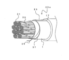
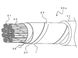
- FIG. 2 is a perspective view of a metallic cable 30a using the laminated tape 1. Sectional drawing of the metallic cable 30a using the laminated tape 1.
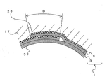
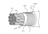
- FIG. The enlarged view of the B section of FIG. FIG. 2 is a perspective view of a metallic cable 30b using the laminated tape 1. Sectional drawing of the metallic cable 30c using the laminated tape 1. Sectional drawing of the metallic cable 30d using the laminated tape 1.
- FIG. 2 is a cross-sectional view of the optical cable 40 using the laminate tape 1. Sectional drawing of the leaky coaxial cable 60.
- FIG. 1 is a sectional view of the laminate tape 1.
- the laminate tape 1 has a resin layer 5 and a metal layer 3 laminated on the resin layer 5.
- the laminate tape 1 is used by being wound around the inside of a cable jacket.
- the metal layer 3 of the laminate tape 1 is not particularly limited, but aluminum (including an aluminum alloy), stainless steel, copper (including a copper alloy), or steel can be used.
- An adhesive layer (not shown) may be provided on the surface of the laminate tape 1 (the surface of the metal layer 3). Further, the resin layer 5 may be laminated on both surfaces of the metal layer 3.
- the resin layer 5 of the laminate tape 1 has a base resin of polyethylene or polypropylene, particularly preferably high-density polyethylene.
- the softening temperature can be set to 75 ° C. or higher.
- the softening temperature of the resin can be measured, for example, according to JIS K7196 (2012).
- the polyethylene or polypropylene constituting the resin layer 5 is made into a kraft by adding maleic acid in an amount of 0.1% by mass or more and 2% by mass or less.
- maleic acid is added to the polyethylene or polypropylene constituting the resin layer 5 in an amount of 0.2% by mass or more and 1.5% by mass or less, more preferably 0.3% by mass or more and 0.6% by mass or less. It is desirable to add 9.9 mass% or more and 1.2 mass% or less.
- the melt flow rate of the polyethylene or polypropylene constituting the resin layer 5 specified in JIS K692-2-2 can be set to 0.2 g / 10 min or more and 20 g / 10 min or less. More desirably, the melt flow rate of polyethylene or polypropylene forming the resin layer 5 is 1.0 g / 10 min or more and 15 g / 10 min or less.
- melt flow rate is too low, the productivity will deteriorate. On the other hand, if the melt flow rate is too high, there is a possibility that a problem may occur in the shape retention during production.
- the melt flow rate can be measured, for example, according to JIS K7210-1 (2014).
- the resin layer 5 preferably has a Shore D hardness of 45 or more. This is because if the Shore D hardness of the resin layer 5 is too low, the rigidity of the cable decreases when the resin layer 5 is used for a cable.
- the laminated tape 1 preferably has an overall tensile strength at break of 10 MPa or more. By increasing the tensile strength at break of the laminate tape 1, when used for a cable, the tensile strength of the cable can be increased.
- the laminate tape 1 preferably has a yield point stress of 5 MPa or more. By increasing the yield point stress of the laminate tape 1, when used for a cable, the durability of the cable can be increased.
- the thickness of the laminate tape 1 is not particularly limited, but is preferably, for example, 0.05 mm to 0.2 mm. If the thickness of the laminate tape 1 is further reduced, the strength of the cable is reduced. Further, when the thickness of the laminate tape 1 is further increased, the strength becomes stronger, but new problems such as weight reduction occur.
- the thickness of the resin layer 5 is 0.03 mm to 0.40 mm. If the thickness of the resin layer 5 is further reduced, the adhesiveness is improved, but the production yield is reduced. Conversely, if the thickness of the resin layer 5 is further increased, new problems such as deterioration of the environmental resistance of the cable occur.
- the ratio of the thickness of the resin layer 5 to the thickness of the metal layer 3 is 0.3 ⁇ the thickness of the resin layer 5 / the thickness of the metal layer 3 ⁇ 1.2. By doing so, it is possible to obtain an effect of preventing a reduction in manufacturing variation of the laminated tape. Further, the peel strength between the metal layer 3 and the resin layer 5 is desirably 2.9 N / mm 2 or more.
- FIG. 2 is a perspective view showing the metallic cable 30a
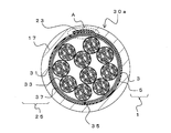
- FIG. 3 is a sectional view.
- the metallic cable 30a mainly includes, in order from the inside, a plurality of covered conductors 31, a holding tape 37, a laminate tape 1, a jacket 17, and the like.
- the covered conductor 31 includes a conductor and an insulating covering that covers the conductor.
- the conductor of the covered conductor 31 is made of, for example, aluminum or copper, and may be a single wire as shown or a stranded wire (not shown).
- An insulating coating is provided on the outer periphery of the conductor. The insulating coating is formed over substantially the entire length of the conductor. The insulating coating is formed of an insulating resin. Although the coated conductor 31 including the conductor and the insulating coating is used as a single wire, two wires may be twisted to form a pair wire, or four wires may be twisted to form a quad wire.
- the plurality of covered conductors 31 are bundled by the coarsely wound cord 33.
- a presser winding tape 37 is further wound around the outer circumference of the plurality of bundles composed of the plurality of covered wires 31 at a time.
- the plurality of covered conductors 31 bundled with the holding tape 37 are referred to as a cable core 25. Since the holding tape 37 only needs to be able to bundle the plurality of covered conductors 31, it may be a coarsely wound cord or the like.
- a method of twisting a pair wire or a quad wire into a unit and forming the unit by further twisting or a method of forming a single-core wire, a pair wire, and a quad wire on a central layer.
- a method of twisting and further twisting a first layer, a second layer and a single core wire, a pair wire, and a quad wire on the upper layer are various methods such as a method of twisting and further twisting a first layer, a second layer and a single core wire, a pair wire, and a quad wire on the upper layer.
- the laminate tape 1 is wound around the outer periphery of the holding tape 37.
- the laminate tape 1 is wound with a vertical wrap so that both ends in the width direction wrap in the circumferential direction. That is, the laminated tape 1 is wound around the outer periphery of the cable core 25 so that the axial direction of the cable core 25 and the longitudinal direction of the laminated tape 1 are aligned, and the wrap portions 23 at both ends of the laminated tape 1 are formed in a substantially straight line. Is done.
- a jacket 17 is provided on the outer periphery of the laminate tape 1.
- the outer cover 17 is provided so as to cover the outer periphery of the laminate tape 1. That is, the laminate tape 1 wound around the outer periphery of the cable core portion 25 is disposed inside the outer cover 17, and the outer cover 17 is provided on the outermost periphery of the cable core portion 25.
- the outer cover 17 is made of resin, and for example, a resin such as polyethylene or polyolefin to which carbon black or the like is added can be used.
- the laminate tape 1 functions as a moisture permeation preventing layer. That is, it is possible to restrict the humidity infiltration path by making the resin layer 5 of the laminated tape 1 adhere to both ends in the width direction of the laminated tape 1 and to adhere the laminated tape 1 to the jacket 17. It is also possible to eliminate the resin layer 5 only at both ends in the width direction of the laminate tape 1 and to conduct the metal layers 3 at both ends in the width direction, so that the entire laminate tape can be used as a conductor as a metal tube.
- the outer cover 17 may be not only one layer but also two or more layers.
- the laminate tape 1 can be used even if it is disposed in any inner layer of the outer cover 17.
- the laminate tape 1 may be used in two or more layers.
- a metal outer layer suitable for the purpose may be provided as another layer.
- a tear string 35 is arranged between the laminate tape 1 and the cable core 25. By pulling out the tear string 35, it is possible to tear the laminate tape 1 and the jacket 17 and take out the inner covered conductor 31.
- the number of covered conductors 31 and the number of bundles constituting the cable core portion 25 are not limited to the illustrated example. Further, a composite cable in which an optical fiber or the like is arranged may be used.
- the laminate tape 1 has the wrap portion 23.
- FIG. 4 is an enlarged view of a portion B in FIG.
- the laminate tape 1 is wound around the outer periphery of the cable core 25 with the resin layer 5 facing outward. That is, the outer cover 17 and the resin layer 5 adhere to each other.
- the metal layer 3 at the outer end of the wrap portion 23 and the resin layer 5 at the inner end are bonded.
- the adhesive layer may not be provided on the laminate tape 1.
- the ends of the laminate tape 1 simply overlap with each other, and some deviation is allowed. Further, the resin layer 5 and the outer cover 17 do not have to be adhered only by being in contact with each other.
- the wrap length (B in the figure) of the wrap portion 23 in the circumferential direction of the laminate tape 1 is preferably 1 mm or more and 2.0 times or less the outer diameter of the metallic cable 30a, and more preferably the outer diameter. 1.5 times or less. If the wrap length is too short, there is a possibility that the water shielding becomes worse due to the displacement of the wrap portion 23 when the metallic cable 30a is bent or the like. On the other hand, if the wrap length is too long, the moisture-permeable layer becomes thicker, which also affects flexibility.
- An insulating coating is formed on the outer periphery of the conductor by, for example, extrusion, to form a coated conductor 31.
- the covered conductor 31 is twisted by a twisting assembly machine. For example, twisting a pair wire or a quad wire into a unit, and twisting the unit or twisting a multilayer pair wire or a quad wire.
- the bundles are bundled with the coarsely wound cord 33 as necessary.
- the plurality of bundles are collectively wound around the holding tape 37 to form the cable core portion 25.
- the holding tape 37 may be a coarsely wound cord or the like, as long as it can bundle the assembled cores.
- the laminate tape 1 in which the resin layer 5 and the metal layer 3 are bonded in advance is supplied, and is vertically wound around the outer periphery of the press-winding tape 37 (the cable core portion 25) by a forming machine or the like to form a moisture-permeable layer. Is done.
- An outer jacket 17 is extruded and integrated with the outer periphery of the moisture-permeable layer formed by the laminate tape 1. Extrusion processing may be forming and a series of simultaneous processing. Thus, the metallic cable 30a is manufactured.
- the softening temperature of the resin layer 5 of the laminate tape 1 is 75 ° C. or higher, it is possible to secure a sufficient environmental temperature resistance even in the recent rise in temperature.
- FIG. 5 is a perspective view showing the metallic cable 30b.
- the same components as those of the metallic cable 30a are denoted by the same reference numerals as those in FIGS. 1 to 4, and redundant description will be omitted.
- the metallic cable 30b has substantially the same configuration as the metallic cable 30a, except that the laminated tape 1 is corrugated.
- the corrugated shape of the laminate tape 1 is formed such that peaks and troughs are repeated in the longitudinal direction of the cable core portion 25, and each of the peaks and troughs is continuous in the circumferential direction.
- the corrugated shape of the laminated tape 1 may be performed at the time of manufacturing the laminated tape 1, and the corrugated laminated tape 1 may be sent around the outer periphery of the cable core portion 25 and wound, or when the laminated tape 1 is formed. At the same time, a corrugating process may be performed.
- the laminated tape 1 can be used after being subjected to corrugation as required.
- FIG. 6 is a sectional view showing the metallic cable 30c.
- the metallic cable 30c has substantially the same configuration as the metallic cable 30a, except that the laminated tape 1 is spirally wound instead of vertically wrapped.
- the spiral winding may be performed by using one laminated tape 1 so that one end in the width direction of the laminated tape 1 overlaps with the opposite end in the width direction of the laminated tape 1 one round before. Further, one laminated tape 1 is spirally wound at intervals, and one end or both ends in the width direction of another laminated tape 1 are covered with a large number of cables so as to overlap the previously wound laminated tape 1. Can also be wound spirally. Thus, the laminated tape 1 may be spirally wound instead of vertically wrapped.
- FIG. 7 is a sectional view showing the metallic cable 30d.
- the metallic cable 30d has an inner sheath 39.
- a plurality of covered conductors 31 are bundled with a coarsely wound cord 33, and a presser winding tape 37 is wound around the outer periphery of the plurality of bundles.
- a coarsely wound string or the like may be used as the holding roll.
- the first laminate tape 1 forms a wrap portion 23 and is vertically wrapped around the outer periphery of the holding tape 37 (the cable core portion 25). As described above, the laminate tape 1 may be spirally wound, but in the following description, an example in which the laminate tape 1 is vertically wound will be described.
- an inner sheath 39 is formed on the outer periphery of the first laminated tape 1.
- the inner sheath 39 is formed, for example, by extrusion.
- the second laminate tape 1 is further wound around the outer periphery of the inner sheath 39.
- a jacket 17 is provided on the outer periphery of the outer second laminate tape 1 and on the outermost periphery of the metallic cable 30d. That is, the second laminate tape 1 is disposed inside the jacket 17.
- the outer cover 17 is provided so as to cover the outer periphery of the second laminate tape 1 and is adhered to the resin layer 5 of the second laminate tape 1.
- the metallic cable 30 d has two resin layers of the outer cover 17 and the inner sheath 39, and the laminate tape 1 is wound in two layers inside each of the outer cover 17 and the inner sheath 39.
- the laminate tape 1 may be a single layer only on the inner side of the outer cover 17 or the inner sheath 39.
- an exterior suitable for the purpose may be provided inside the outer sheath 17 or the inner sheath 39 where the laminate tape 1 is not arranged.
- iron may be wound to prevent electromagnetic induction, or stainless steel may be wound to prevent bird and animal damage.
- the space between the first laminate tape 1 on the inner peripheral side and the presser winding tape 37 (the cable core portion 25) and the second laminate tape on the outer peripheral side are formed.
- the tear strings 35a and 35b are arranged between the tapes 1, respectively. By doing so, by pulling out the tear string 35b, the outer laminate tape 1 and the outer cover 17 can be torn to expose the inner sheath 39. Further, by further pulling out the tear string 35a, the inner laminated tape 1 and the inner sheath 39 can be torn apart and the inner covered conductor 31 can be taken out.
- the cable core portion 25 includes the portion up to the holding tape 37.
- the cable core portion 25 including the inner sheath 39 may be used.
- the laminate tape 1 is wound around the outer periphery of the cable core.
- only the resin may be used without providing the laminate tape 1 inside the inner sheath 39.
- the inner sheath 39 is provided, and the tear strings 35a and 35b are provided at the respective portions, whereby the outer cover 17 and the inner sheath 39 and the like can be separately torn. And the tearing of the tear string can be suppressed.
- FIG. 8 is a sectional view showing the optical cable 40.
- the optical cable 40 includes a tension member 41, a spacer 43, an optical fiber ribbon 47, an inner sheath 39, a laminate tape 1, an outer cover 17, and the like.
- the spacer 43 is made of a flexible resin.
- a plurality of grooves 45 are provided on the outer periphery of the spacer 43, and the grooves 45 are formed continuously in a spiral shape in one direction with respect to the longitudinal direction of the spacer 43 or in an SZ shape in both directions repeatedly.
- a tension member 41 is provided at the center of the spacer 43.
- a plurality of optical fiber ribbons 47 are accommodated in the groove 45.
- the optical fiber ribbon 47 is, for example, an optical fiber ribbon in which adjacent optical fibers are bonded to each other with a UV resin, and is an intermittent optical fiber ribbon that is intermittently bonded in a longitudinal direction. Is also good.
- a presser winding tape 49 is wound around the outer periphery of the spacer 43 by vertical attachment or spiral winding.
- An inner sheath 39 is provided on the outer periphery of the holding tape 49 (the cable core portion 25).
- the inner sheath 39 is formed by, for example, extrusion molding.
- a protective tape 53 is wound around the outer periphery of the inner sheath 39.
- the inner sheath 39 and the protection tape 53 are made of resin, and the inner sheath 39 and the protection tape 53 are not bonded.
- the laminate tape 1 is wound around the outer periphery of the protective tape 53. As described above, the laminate tape 1 is provided with the wrap portion 23 with the resin layer 5 as the outer periphery, and is vertically wound.
- the cable core portion 25 up to the holding tape 49 is used.
- the cable core portion may include the inner sheath 39 and the protective tape 53, and only the inner sheath 39 is used without using the protective tape 53. May be included in the cable core section.
- the laminate tape 1 is wound around the outer periphery of the cable core. That is, in the present invention, the fact that the laminate tape 1 is wound around the outer periphery of the cable core portion includes that another structure such as the protective tape 53 is provided between the cable core portion and the laminate tape 1.
- the laminated tape 1 may be smooth or may be subjected to a corrugating process.
- the laminate tape 1 may be either a vertically wrapped or spiral wound. Further, the layer on which the laminate tape 1 is not applied may be provided with an exterior suitable for the purpose.
- An outer jacket 17 is provided on the outer circumference of the laminate tape 1 and on the outermost circumference of the optical cable 40. That is, the laminate tape 1 is disposed inside the outer cover 17.
- the outer cover 17 is provided so as to cover the outer periphery of the laminate tape 1 and is adhered to the resin layer 5 of the laminate tape 1.
- a tear string is arranged between the laminate tape 1 and the cable core 25.
- a tear string 35a is arranged between the holding tape 49 (the cable core portion 25) and the inner sheath 39
- a tear string 35b is arranged between the protective tape 53 and the laminate tape 1. .
- the laminate tape 1 and the outer cover 17 can be torn to expose the inner protective tape 53 and the like.
- the inner sheath 39 and the protective tape 53 can be torn apart and the inner optical fiber tape core 47 can be taken out.
- the shape, the number and the depth of the grooves 45, the configuration of the optical fiber ribbon 47, and the like are not limited to the illustrated example. Further, the inner sheath 39 and the protective tape 53 are not always necessary.
- the laminated tape 1 by applying the laminated tape 1 to the optical cable 40, it is possible to obtain an optical cable having excellent water resistance and excellent environmental resistance as well as ensuring water shielding. Further, it is also possible to form the resin layer 5 so that the wrap portion 23 of the laminate tape 1 can be easily attached, and to further improve the water shielding property.
- FIG. 9 is a perspective view showing the leaky coaxial cable 60.
- the leaky coaxial cable 60 includes an inner conductor 61, an insulator 62, an outer conductor 63, a slot 64, a hold-down winding 65, a jacket 17, a support wire 66, and the like.
- the inner conductor 61 has a corrugated shape such as a pipe or a corrugate, and may be made of, for example, aluminum or copper.
- An insulator 62 is provided on the inner conductor 61.
- As the insulator 62 one or a plurality of string-shaped insulators of FIG. 9 are arranged on the internal conductor, and a pipe-shaped insulator is further arranged thereon.
- the insulator 62 is expected to function as a base for adjusting the dielectric constant and winding the outer conductor.
- a dielectric such as polyethylene can be used.
- the insulator 62 may be formed by extruding foamed polyethylene or the like whose foaming rate is adjusted on the internal conductor.
- An outer conductor 63 having a slot 64 is vertically wound on the insulator 62, and a holding roll 65 is spirally wound thereon.
- the laminated tape 1 can be used for the outer conductor 63, and the laminated tape 1 may be subjected to corrugation as in this embodiment.
- the structure in which the inner conductor 61 and the insulator 62 are used as a cable core portion and the laminate tape 1 is wound thereon is the same as that of the above-described metallic cable or optical cable.
- the cable with a support wire also has a support wire 66. When the support wire 66 is prepared separately from the cable, a round leaky coaxial cable without the support wire 66 may be used.
- the laminate tape 1 provided with the slot 64 as the external conductor 63 is wrapped around the outer periphery of the insulator 62 by vertically wrapping.
- the resin layer 5 (not shown) in the wrap area is removed to make the laminate tape 1 conductive at both ends, thereby electrically connecting the laminate tape 1. It can be pipe-shaped.
- the resin layer 5 serves as a strong support for the metal layer 3, and the environmental resistance can be improved.
- the resin layer 5 having high temperature resistance as in the present embodiment, It can be used in high temperature environments.
- the laminate tape 1 is wound on the insulator 62 as the external conductor 63.
- a holding roll is applied on the insulator 62 for protection and heat resistance, and the laminated tape is formed on the holding roll as the external conductor 63. 1 may be wound.
- the laminated tape 1 can be suitably applied to various kinds of cables.
Abstract
ラミネートテープ1は、樹脂層5と、樹脂層5に積層される金属層3を有する。ラミネートテープ1は、ケーブルの外被の内側に巻き付けられて用いられる。ラミネートテープ1の樹脂層5は、ベース樹脂がポリエチレンまたはポリプロピレンである。ポリエチレンまたはポリプロピレンを適用することで、軟化温度を75℃以上とすることができる。樹脂層5を構成するポリエチレンまたはポリプロピレンには、添加剤としてマレイン酸が0.1質量%以上2質量%以下で添加され。このようにすることで、樹脂層5を構成するポリエチレンまたはポリプロピレンのメルトフローレートをJIS K6922-2で規定されるメルトフローレートが0.2g/10min以上20g/10min以下とすることができる。
Description
本発明は、樹脂層と金属層とが積層したラミネートテープと、このラミネートテープがケーブルコア部の外周に巻き付けられたケーブルに関するものである。
従来、通信ケーブル等において、金属層と樹脂層からなるラミネートテープが用いられている。このようなラミネートテープによれば、ケーブルの引張強度の確保や、難燃性、遮水性、遮蔽性等を付与することができる(例えば特許文献1~特許文献5)。
ケーブルは、環境温度に対して耐える必要がある。このため、ケーブルには、耐環境温度が要求され、60℃を上限するのが一般的であった。すなわち、60℃においても、ラミネートテープが軟化することがなく、防水性等が劣化しないことが要求される。
しかし、近年の異常気象やグローバル化に伴い、日中の最高気温記録は国内でも約41℃であり、海外に至っては50℃を超える場合もある。さらには日照による温度上昇を加味すると、従来の耐環境温度では十分とは言えない状況となっている。耐環境温度以上の温度で使用すると、ラミネートテープの樹脂層が軟化し、接着が剥がれて強度低下を引き起こしたり、ラミネートテープのラップ部で凸部が発生したりする不具合が発生するおそれがある。
このように、より高い温度で使用可能な、耐環境温度の高いケーブルが要求されているが、特許文献1~特許文献5のように、従来のケーブルでは、このような耐環境温度については考慮されていなかった。
一方、より高い耐環境温度を得るためには、樹脂層の軟化温度を上げる方法がある。しかし、軟化温度を上げるため、単に、従来使用されているEVA(エチレン・酢酸ビニル共重合体)より軟化点が高い材料を選ぶと、ラミネートテープの製造時に、従来よりも高い温度で加工する必要があり、耐熱性が高い設備への改造が必要になった。
本発明は、このような問題に鑑みてなされたもので、製造性に優れ、軟化温度が高く、高い耐環境温度を有するラミネートテープと、これを用いたケーブルを提供することを目的とする。
前述した目的を達成するため、第1の発明は、ケーブルの外被の内側に用いられるラミネートテープであって、樹脂層と、金属層とが積層され、前記樹脂層は、ベース樹脂がポリエチレンまたはポリプロピレンであり、マレイン酸が0.1質量%以上2質量%以下で添加され、軟化温度が75℃以上であり、JIS K6922-2で規定されるメルトフローレートが0.2g/10min以上20g/10min以下であることを特徴とするラミネートテープである。
前記ベース樹脂は、高密度ポリエチレンであることが望ましい。
前記ベース樹脂には、マレイン酸が0.2質量%以上1.5質量%以下添加されることがより好ましい。
前記金属層がアルミニウム、ステンレス、銅またはスチールであることが好ましい。
前記樹脂層のショアD硬度が45以上であることが望ましい。
引張破断強度が10MPa以上であることが望ましい。
降伏点応力が5MPa以上であることが望ましい。
本発明によれば、ポリエチレンまたはポリプロピレンにマレイン酸を0.1質量%以上2質量%以下添加することで、75℃以上の軟化温度を確保することができ、高い耐環境温度を得ることができる。また、JIS K6922-2で規定されるメルトフローレートが0.2g/10min以上20g/10min以下になり、高温対応の設備変更が少なく製造でき、製造性にも優れる。
特に、ベース樹脂が高密度ポリエチレンであれば、設備変更は不要になる点で望ましい。
また、マレイン酸を0.2質量%以上1.5質量%以下添加することで、さらに接着強度が高くなる点で望ましい。
また、金属層がアルミニウム、ステンレス、銅またはスチールであれば、従来のラミネートテープと同様に取り扱うことができる。
また、樹脂層のショアD硬度が45以上であれば、ケーブルに用いた際に、十分な剛性を得ることができる。
また、引張破断強度が10MPa以上であれば、ケーブルに用いた際に、十分な引張強度を得ることができる。
同様に、降伏点応力が5MPa以上であれば、十分な耐久性を確保することができる。
第2の発明は、第1の発明に係るラミネートテープを用いたケーブルであって、ケーブルコア部と、前記ケーブルコア部の最外周に設けられる外被と、前記外被の内側に配置され、前記ケーブルコア部の外周に巻き付けられるラミネートテープと、を具備し、前記ラミネートテープは、前記樹脂層を外側に向けて配置され、両端部が周方向にラップするように巻き付けられることを特徴とするケーブルである。
前記外被は、難燃性樹脂を施してもよい。
前記ラミネートテープの周方向に対するラップ長さは、1mm以上かつケーブル外径の2.0倍以下であることが好ましく、1mm以上かつケーブル外径の1.5倍以下にするとさらに好ましい。前記ラミネートテープの両端部でラップする箇所のみ前記樹脂層の無い金属層だけとして、前記ラミネートテープの両端部を導通させ、電気的に円筒とすることもできる。
前記ラミネートテープに波付加工が施してもよい。
前記ケーブルコア部の外周に、内部シースを具備し、前記ラミネートテープを、前記内部シースの外周に設け、前記ケーブルコア部と前記内部シースとの間と、前記ラミネートテープと前記内部シースとの間のそれぞれに引き裂き紐が配置されてもよく、適当な位置に保護テープを配置してもよい。
前記ケーブルコア部の外周に設けられる第1の前記ラミネートテープと、第1の前記ラミネートテープの外周に設けられる内部シースと、前記内部シースの外周に設けられる第2の前記ラミネートテープと、第2の前記ラミネートテープの外周に設けられる前記外被と、を具備し、前記ケーブルコア部と第1の前記ラミネートテープとの間と、前記内部シースと第2の前記ラミネートテープとの間のそれぞれに引き裂き紐が配置されてもよく、適当な位置に保護テープを配置してもよい。
第2の発明によれば、金属層と樹脂層とからなるラミネートテープが、ケーブルコア部の外周に隙間なく巻き付けられるため、高い遮水性を確保することができる。また、ポリエチレンまたはポリプロピレンにマレイン酸を0.1質量%以上2質量%以下添加することで、75℃以上の軟化温度を確保することができ、高い耐環境温度を得ることができる。また、JIS K6922-2で規定されるメルトフローレートが所定の範囲になり、高温対応の設備変更が少なく製造でき、製造性にも優れる。
また、ラップ部の周方向に対するラップ長さが、1mm以上であればラップ部が剥がれて隙間が空くことがない。また、ラップ部の周方向に対するラップ長さが、ケーブル外径の2.0倍以下であれば、ラップにより厚みの厚い部分を少なくでき、ケーブル外径の1.5倍以下であればより少なくすることができる。
また、ラミネートテープに波付け加工を施すことで、ケーブルの可撓性を高めることができる。
また、ケーブルコア部の外周に内部シースが設けられる場合に、内部シースとケーブルコア部との間、およびラミネートテープと内部シースとの間に引き裂き紐を配置すれば、引き裂き紐によってケーブルコア部を容易に取り出すことができる。
また、ケーブルコア部の外周に、ラミネートテープを2層で巻き付けることで、より高い遮水性を確保することができる。また、外層のラミネートテープを例えばステンレスやスチールなどのような材質を使用することで鳥獣害からの保護や直埋の土圧からの保護などが可能となる。この際、引き裂き紐を2層のラミネートテープの内側のそれぞれに配置することで、引き裂き紐によって、より容易にケーブルコア部を取り出すことができる。
本発明によれば、製造性に優れ、軟化温度が高く、高い耐環境温度を有するラミネートテープと、これを用いたケーブルを提供することができる。
以下、図面を参照しながら、本発明の実施形態について説明する。図1は、ラミネートテープ1の断面図である。ラミネートテープ1は、樹脂層5と、樹脂層5に積層される金属層3を有する。ラミネートテープ1は、ケーブルの外被の内側に巻き付けられて用いられる。
ラミネートテープ1の金属層3としては、特に限定されないが、アルミニウム(アルミニウム合金を含む)、ステンレス、銅(銅合金を含む)またはスチールを適用可能である。なお、ラミネートテープ1の表面(金属層3の表面)には、図示を省略した接着剤層が設けられてもよい。また、金属層3の両面に樹脂層5を積層させてもよい。
ラミネートテープ1の樹脂層5は、ベース樹脂がポリエチレンまたはポリプロピレンであり、特に、高密度ポリエチレンであることが望ましい。ポリエチレンまたはポリプロピレンを適用することで、軟化温度を75℃以上とすることができる。なお、樹脂の軟化温度は、例えばJIS K7196(2012)で測定することができる。
樹脂層5を構成するポリエチレンまたはポリプロピレンは、マレイン酸を0.1質量%以上2質量%以下添加することでクラフト化する。好ましくは、樹脂層5を構成するポリエチレンまたはポリプロピレンに、マレイン酸を0.2質量%以上1.5質量%以下、より好ましくはマレイン酸を0.3質量%以上0.6質量%以下又は0.9質量%以上1.2質量%以下添加することが望ましい。このようにすることで、樹脂層5を構成するポリエチレンまたはポリプロピレンの、JIS K6922-2で規定されるメルトフローレートを0.2g/10min以上20g/10min以下とすることができる。なお、より望ましくは、樹脂層5を構成するポリエチレンまたはポリプロピレンのメルトフローレートは1.0g/10min以上15g/10min以下である。
メルトフローレートが低すぎると、製造性が悪化する。一方、メルトフローレートが高すぎると、製造時における形状維持性に問題が生じるおそれがある。なお、メルトフローレートは、例えば、JIS K7210-1(2014)で測定することができる。
樹脂層5のショアD硬度は、45以上であることが望ましい。樹脂層5のショアD硬度が低すぎると、ケーブルに用いた際に、ケーブルの剛性が低くなるためである。
ラミネートテープ1は、全体としての引張破断強度が10MPa以上であることが望ましい。ラミネートテープ1の引張破断強度を高くすることで、ケーブルに用いた際に、ケーブルの引張強度を高めることができる。
また、ラミネートテープ1は、降伏点応力が5MPa以上であることが望ましい。ラミネートテープ1の降伏点応力を高くすることで、ケーブルに用いた際に、ケーブルの耐久性を高めることができる。
また、ラミネートテープ1の厚さは特に限定されないが、例えば、0.05mm~0.2mmであることが望ましい。これ以上、ラミネートテープ1の厚みを薄くするとケーブルの強度が劣化する。また、これ以上、ラミネートテープ1の厚みを厚くすると強度的に強くなるが、軽量化等の新たな課題が発生する。
また樹脂層5の厚さは0.03mm~0.40mmであることが望ましい。これ以上、樹脂層5の厚さを薄くすると、接着性は向上するが製造歩留まりが低化する。逆にこれ以上樹脂層5の厚さを厚くすると、ケーブルの耐環境性の劣化等の新たな課題が発生する。
なお、樹脂層5と金属層3の厚さの比は、0.3≦樹脂層5の厚さ/金属層3の厚さ≦1.2にすることが望ましい。このようにすることで、ラミネートテープの製造ばらつきの低下を防ぐ効果を得ることができる。また、金属層3と樹脂層5との剥離強度は、2.9N/mm2以上であることが望ましい。
次に、ラミネートテープ1が使用されたケーブルの一例について説明する。図2は、メタリックケーブル30aを示す斜視図であり、図3は断面図である。
メタリックケーブル30aは、主に、内部側から順に、複数の被覆導線31と押さえ巻きテープ37とラミネートテープ1と外被17等から構成される。被覆導線31は、導体と、導体を被覆する絶縁被覆とからなる。
被覆導線31の導体は、例えばアルミニウム製や銅製であり、図示した様な単線のものや図には無いが撚線のものも使用することができる。導体の外周には、絶縁被覆が設けられる。絶縁被覆は、導体の略全長にわたって形成される。絶縁被覆は、絶縁性を有する樹脂によって形成される。なお、導体と絶縁被覆を含めた被覆導線31は単線でも使用されるが、2本を撚り合わせてペア線としたり、4本を撚り合わせてカッド線とすることもある。
複数の被覆導線31は粗巻き紐33によって束ねられる。複数の被覆導線31からなる複数の束の外周には、さらに、一括して押さえ巻きテープ37が巻き付けられる。なお、メタリックケーブル30aにおいては、押さえ巻きテープ37で束ねられた複数の被覆導線31をケーブルコア部25とする。押さえ巻きテープ37は複数の被覆導線31を束ねられればよいため、粗巻き紐などでもよい。
ここで、ケーブルコア部25を形成する方法としては、ペア線やカッド線を撚り合わせてユニット化し、ユニットをさらに撚り合わせて形成する方法や、中心層に単心線、ペア線、カッド線を撚り合わせてさらにその上層に1層目、2層目と単心線、ペア線、カッド線を撚り合わせる方法など多様である。
押さえ巻きテープ37の外周には、ラミネートテープ1が巻き付けられる。ラミネートテープ1は、幅方向の両端部が周方向にラップするように縦添え巻で巻き付けられる。すなわち、ケーブルコア部25の軸方向とラミネートテープ1の長手方向とを合わせてラミネートテープ1をケーブルコア部25の外周に巻き付け、ラミネートテープ1の両端部のラップ部23は、略直線状に形成される。
ラミネートテープ1の外周には、外被17が設けられる。外被17は、ラミネートテープ1の外周を覆うように設けられる。すなわち、ケーブルコア部25の外周に巻き付けられるラミネートテープ1は、外被17の内側に配置され、外被17はケーブルコア部25の最外周に設けられる。
なお、外被17は樹脂製であり、例えば、カーボンブラック等を添加したポリエチレンやポリオレフィンなどの樹脂が適用可能である。
メタリックケーブル30aにおいては、ラミネートテープ1は、透湿防止層として機能する。すなわち、ラミネートテープ1の一部の樹脂層5がラミネートテープ1の幅方向の両端を密着させ、ラミネートテープ1と外被17を密着させることで湿度の浸入経路を制限することが可能となる。ラミネートテープ1の幅方向の両端だけ樹脂層5を無くして幅方向の両端で金属層3を導通させ、金属管としてラミネートテープ全体を導体として使用することもできる。
なお、外被17は、1層だけでなく2層以上であってもよく、この場合には、ラミネートテープ1はいずれの外被17の内層に配置しても使用できる。またラミネートテープ1は2層以上で使用してもよく、ラミネートテープ1とは別に、他の層として目的に合った金属外装を施してもよい。
メタリックケーブル30aは、ラミネートテープ1とケーブルコア部25の間に引き裂き紐35が配置される。引き裂き紐35を引き出すことで、ラミネートテープ1と外被17とを引き裂いて、内部の被覆導線31を取り出すことが可能である。
なお、メタリックケーブル30aにおいて、ケーブルコア部25を構成する被覆導線31の本数や、束数は図示した例には限られない。また、さらに、光ファイバ等が配置された複合ケーブルであってもよい。
前述したように、ラミネートテープ1は、ラップ部23を有する。図4は、図3のB部拡大図であり、ラップ部23の拡大図である。ラミネートテープ1は、樹脂層5を外側にしてケーブルコア部25の外周に巻き付けられる。すなわち、外被17と樹脂層5とが接着する。また、ラップ部23においては、ラップ部23の外側の端部の金属層3と内側の端部の樹脂層5とが接着する。
なお、ラミネートテープ1には接着剤層が設けられなくてもよい。この場合には、ラップ部23では、単にラミネートテープ1の端部同士が重なり合い、多少のずれが許容される。また、樹脂層5と外被17とは、単に接触しているだけで接着されていなくてもよい。
ここで、ラミネートテープ1の周方向におけるラップ部23のラップ長さ(図中B)は、1mm以上かつメタリックケーブル30aの外径の2.0倍以下であることが望ましく、より望ましくは外径の1.5倍以下であることがよい。ラップ長が短すぎると、メタリックケーブル30aの曲げ時等において、ラップ部23のずれによる遮水性の悪化等のおそれがある。一方、ラップ長が長すぎると、透湿防止層が厚くなり可撓性にも影響がでる。
次に、メタリックケーブル30aの製造方法について説明する。導体の外周に、例えば押出加工で絶縁被覆を形成して、被覆導線31を形成する。次に、被覆導線31を撚り合わせ集合機にて撚り合わせる。例えば、ペア線やカッド線を撚り合わせてユニット化し、そのユニットの撚り合わせや、または多層のペア線やカッド線の撚り合わせを行う。この際、必要に応じてそれぞれの束を粗巻き紐33で束ねる。さらに、これらの複数の束を一括して押さえ巻きテープ37で巻き付けて、ケーブルコア部25を形成する。押さえ巻きテープ37は粗巻き紐などでもよく、集合したコアを束ねることができればよい。予め樹脂層5と金属層3等を貼り合わせたラミネートテープ1を供給して、フォーミングマシン等によって、押さえ巻きテープ37(ケーブルコア部25)の外周に縦巻きフォーミングして透湿防止層が形成される。
ラミネートテープ1により形成された透湿防止層の外周には、外被17が押出加工されて一体化される。押出加工はフォーミングと一連の同時加工でもよい。以上によりメタリックケーブル30aが製造される。
以上、本実施の形態によれば、ラミネートテープ1の樹脂層5の軟化温度が75℃以上であるため、近年の気温の上昇に対しても、十分な耐環境温度を確保することができる。
また、樹脂層5の軟化温度を高くしても、メルトフローレートが所定以上を確保することができるため、製造性にも優れる。
次に、第2の実施形態について説明する。図5は、メタリックケーブル30bを示す斜視図である。なお、以下の説明において、メタリックケーブル30aと同様の構成については、図1~図4と同一の符号を付し、重複する説明を省略する。
メタリックケーブル30bは、メタリックケーブル30aとほぼ同様の構成であるが、ラミネートテープ1に、波付加工が施される点で異なる。ラミネートテープ1の波付形状は、ケーブルコア部25の長手方向に対して山谷が繰り返され、山部と谷部のそれぞれが周方向に連続するように形成される。
ラミネートテープ1の波付形状は、ラミネートテープ1の製造時に行って、波付形状のラミネートテープ1をケーブルコア部25の外周に送って巻きつけてもよく、または、ラミネートテープ1をフォーミングする際に、同時に波付け加工を行ってもよい。
このように、ラミネートテープ1は、必要に応じて波付け加工が施されて使用することもできる。
次に、第3の実施形態について説明する。図6は、メタリックケーブル30cを示す断面図である。メタリックケーブル30cは、メタリックケーブル30aとほぼ同様の構成であるが、ラミネートテープ1が縦添え巻きではなく、螺旋巻きされる点で異なる。
なお、螺旋巻きは、1枚のラミネートテープ1を用い、ラミネートテープ1の幅方向の片端が、1周前のラミネートテープ1の幅方向の反対端に重なるように巻き付けてもよい。また、1枚のラミネートテープ1を、間隔を空けて螺旋巻きし、他のラミネートテープ1の幅方向の片端または両端を、先に巻き付けたラミネートテープ1に重なるように多数枚でケーブルを覆うように螺旋巻きで巻き付けることもできる。このように、ラミネートテープ1は、縦添え巻ではなく螺旋巻きしてもよい。
次に、第4の実施形態について説明する。図7は、メタリックケーブル30dを示す断面図である。メタリックケーブル30dは、内部シース39を有する。メタリックケーブル30dは、メタリックケーブル30a、30b、30cと同様に、複数の被覆導線31が粗巻き紐33で束ねられ、この複数の束の外周に押さえ巻きテープ37が巻き付けられる。押さえ巻きとしては、複数の束を束ねることができればよく、粗巻き紐などでもよい。また、押さえ巻きテープ37(ケーブルコア部25)の外周には、第1のラミネートテープ1がラップ部23を形成して縦添え巻される。なお、前述したように、ラミネートテープ1は螺旋巻きでもよいが、以下の説明では、ラミネートテープ1が縦添え巻された例を説明する。
メタリックケーブル30dでは、第1のラミネートテープ1の外周に、内部シース39が形成される。内部シース39は、例えば押出によって成形される。内部シース39の外周には、さらに第2のラミネートテープ1が巻き付けられる。
外側の第2のラミネートテープ1の外周であって、メタリックケーブル30dの最外周には、外被17が設けられる。すなわち、第2のラミネートテープ1は、外被17の内側に配置される。外被17は、第2のラミネートテープ1の外周を覆うように設けられて、第2のラミネートテープ1の樹脂層5と接着される。すなわち、メタリックケーブル30dは、外被17と内部シース39の2層の樹脂層を有し、外被17と内部シース39のそれぞれの内側に、ラミネートテープ1が2層に巻き付けられる。なお、外被17と内部シース39の2層の樹脂層を有する場合において、ラミネートテープ1は外被17か内部シース39のいずれかの内側のみの1層としてもよい。この場合には、ラミネートテープ1を配置していない外被17か内部シース39の内側には目的に合った外装を施してもよい。外装の例として、鉄を巻き付けて電磁誘導対策としたり、ステンレスを巻き付けて鳥獣害対策としてもよい。
このように、内部シース39を設ける際には、内周側の第1のラミネートテープ1と押さえ巻きテープ37(ケーブルコア部25)との間と、内部シース39と外周側の第2のラミネートテープ1の間に、それぞれ引き裂き紐35a、35bが配置される。このようにすることで、引き裂き紐35bを引き出すことで、外側のラミネートテープ1と外被17とを引き裂いて、内部シース39を露出させることができる。また、さらに引き裂き紐35aを引き出すことで、内側のラミネートテープ1と内部シース39とを引き裂いて、内部の被覆導線31を取り出すことが可能である。
なお、本実施形態では、押さえ巻きテープ37までをケーブルコア部25としたが、内部シース39を含めてケーブルコア部25としてもよい。いずれの場合でも、ラミネートテープ1は、ケーブルコア部の外周に巻き付けられることとなる。なお、内部シース39の内側にはラミネートテープ1を設けずに樹脂だけとしてもよい。
このように、メタリックケーブル30a、30b、30c、30dにラミネートテープ1を適用することで、遮水性を確保することができるとともに、耐環境性にも優れたメタリックケーブルを得ることができる。
また、メタリックケーブル30dのように、内部シース39を設け、引き裂き紐35a、35bをそれぞれの部位に設けることで、外被17等と内部シース39等とを別々に引き裂くことができるため、引き裂き作業が容易であり、引き裂き紐の破断等を抑制することができる。
次に、第5の実施形態について説明する。図8は、光ケーブル40を示す断面図である。光ケーブル40は、テンションメンバ41、スペーサ43、光ファイバテープ心線47、内部シース39、ラミネートテープ1、外被17等から構成される。
スペーサ43は、可撓性を有する樹脂で構成される。スペーサ43の外周には、複数の溝45が設けられ、溝45は、スペーサ43の長手方向に対して一方向に螺旋状、または両方向にSZ状に繰り返して連続して形成される。スペーサ43の中央には、テンションメンバ41が設けられる。溝45内には、複数の光ファイバテープ心線47が収容される。光ファイバテープ心線47は、例えば、隣り合う光ファイバ同士がUV樹脂で接着された光ファイバテープ心線であり、長手方向に対して間欠的に接着された間欠光ファイバテープ心線であってもよい。
スペーサ43の外周には、押さえ巻きテープ49が縦添えや螺旋巻などで巻き付けられる。押さえ巻きテープ49(ケーブルコア部25)の外周には内部シース39が設けられる。内部シース39は、例えば押出成形で形成される。また、内部シース39の外周には、保護テープ53が巻き付けられる。内部シース39及び保護テープ53は樹脂製であり、内部シース39と保護テープ53は接着されない。
保護テープ53の外周には、ラミネートテープ1が巻き付けられる。前述したように、ラミネートテープ1は、樹脂層5を外周にして、ラップ部23を設けて縦添え巻きされる。
なお、本実施形態では、押さえ巻きテープ49までをケーブルコア部25としたが、内部シース39および保護テープ53を含めてケーブルコア部としてもよく、保護テープ53を使用せずに内部シース39だけを含めてケーブルコア部としてもよい。前述したように、いずれの場合でも、ラミネートテープ1は、ケーブルコア部の外周に巻き付けられるとする。すなわち、本発明において、ケーブルコア部の外周にラミネートテープ1が巻き付けられるとは、ケーブルコア部とラミネートテープ1の間に保護テープ53等の他の構成が設けられていることを含むものである。さらに前述のメタリックケーブルと同様にラミネートテープ1は平滑でもよいが波付け加工を施してもよい。また、ラミネートテープ1は、縦添え巻と螺旋巻きのいずれであってもよい。また、ラミネートテープ1を施さない層には目的に合った外装を施してもよい。
ラミネートテープ1の外周であって、光ケーブル40の最外周には、外被17が設けられる。すなわち、ラミネートテープ1は、外被17の内側に配置される。外被17は、ラミネートテープ1の外周を覆うように設けられて、ラミネートテープ1の樹脂層5と接着される。
なお、光ケーブル40においても、ラミネートテープ1とケーブルコア部25の間に引き裂き紐が配置される。図示した例では、押さえ巻きテープ49(ケーブルコア部25)と内部シース39との間に引き裂き紐35aが配置され、さらに、保護テープ53とラミネートテープ1との間に引き裂き紐35bが配置される。引き裂き紐35bを引き出すことで、ラミネートテープ1と外被17とを引き裂いて、内部の保護テープ53等を露出させることができる。また、さらに引き裂き紐35aを引き出すことで、内部シース39と保護テープ53とを引き裂いて、内部の光ファイバテープ心線47を取り出すことが可能である。
なお、光ケーブル40において、溝45の形状、配置数や深さや、光ファイバテープ心線47等の構成は図示した例には限られない。また、内部シース39及び保護テープ53は、必ずしも必要ではない。
このように、光ケーブル40にラミネートテープ1を適用することで、遮水性を確保することができるとともに、耐環境性にも優れた光ケーブルを得ることができる。また、ラミネートテープ1のラップ部23が着き易くなるように樹脂層5を形成し、さらに遮水性を向上させることも可能である。
また、引き裂き紐35bと内部シース39との間に、保護テープ53を巻き付けることで、引き裂き紐35bが、内部シース39に食い込んだり密着したりして、引き出すことが困難となることを抑制することができる。
次に、第6の実施形態について説明する。図9は、漏洩同軸ケーブル60を示す斜視図である。漏洩同軸ケーブル60は、内部導体61、絶縁体62、外部導体63、スロット64、押さえ巻65、外被17、支持線66等から構成される。
内部導体61はパイプ状やコルゲートの波付け形状で、材質は例えばアルミニウム製や銅製とすることができる。内部導体61の上には絶縁体62が施される。絶縁体62は図9の1本または複数本の紐状の絶縁体を内部導体上に配置し、さらにその上にパイプ状の絶縁体を配置する。絶縁体62は誘電率を調整し、外部導体を巻き付ける土台の機能が期待され、例えばポリエチレンのような誘電体が使用できる。また絶縁体62は内部導体上に発泡率を調整した発泡ポリエチレン等の押し出し等でもよい。絶縁体62上にはスロット64を有する外部導体63を縦添え巻し、その上に押さえ巻65を螺旋巻きする。ここで外部導体63にラミネートテープ1を使用することができ、本実施例のようにラミネートテープ1は波付け加工を施してもよい。内部導体61と絶縁体62をケーブルコア部とし、その上にラミネートテープ1を巻き付ける構造は前述のメタリックケーブルや光ケーブルと同様である。また支持線付のケーブルでは支持線66も有している。支持線66がケーブルとは別に準備される場合には、支持線66の無い丸型の漏洩同軸ケーブルとしてもよい。
前述のとおり絶縁体62の外周には、外部導体63としてスロット64を施したラミネートテープ1が縦添え巻きでラップ巻きされる。ラミネートテープ1のラップ部23(図示省略)において、ラップ範囲の樹脂層5(図示省略)だけを除去したラミネートテープ1とすることでラミネートテープ1が両端で導通し、ラミネートテープ1を電気的にパイプ状とすることができる。またラミネートテープ1を使用することで樹脂層5が金属層3の強度的なサポートとなり、耐環境性能を向上することができ、本実施形態のように高温耐性を有する樹脂層5とすることで高温環境でも使用できるようになる。
図9では絶縁体62の上に外部導体63としてラミネートテープ1を巻き付けているが、絶縁体62上には保護や耐熱のために押さえ巻を施し、押さえ巻の上に外部導体63としてラミネートテープ1を巻き付けてもよい。
このように、ラミネートテープ1は、各種のケーブルに好適に適用することができる。
以上、添付図を参照しながら、本発明の実施の形態を説明したが、本発明の技術的範囲は、前述した実施の形態に左右されない。当業者であれば、特許請求の範囲に記載された技術的思想の範疇内において各種の変更例または修正例に想到し得ることは明らかであり、それらについても当然に本発明の技術的範囲に属するものと了解される。
例えば、前述した各実施形態の各構成は、互いに組み合わせることができることは言うまでもない。
1………ラミネートテープ
3………金属層
5………樹脂層
17………外被
23………ラップ部
25………ケーブルコア部
30a、30b、30c、30d………メタリックケーブル
31………被覆導線
33………粗巻き紐
35、35a、35b………引き裂き紐
37………押さえ巻きテープ
39………内部シース
40………光ケーブル
41………テンションメンバ
43………スペーサ
45………溝
47………光ファイバテープ心線
49………押さえ巻きテープ
53………保護テープ
60………漏洩同軸ケーブル
61………内部導体
62………絶縁体
63………外部導体
64………スロット
65………押さえ巻
66………支持線
3………金属層
5………樹脂層
17………外被
23………ラップ部
25………ケーブルコア部
30a、30b、30c、30d………メタリックケーブル
31………被覆導線
33………粗巻き紐
35、35a、35b………引き裂き紐
37………押さえ巻きテープ
39………内部シース
40………光ケーブル
41………テンションメンバ
43………スペーサ
45………溝
47………光ファイバテープ心線
49………押さえ巻きテープ
53………保護テープ
60………漏洩同軸ケーブル
61………内部導体
62………絶縁体
63………外部導体
64………スロット
65………押さえ巻
66………支持線
Claims (14)
- ケーブルの外被の内側に用いられるラミネートテープであって、
樹脂層と、金属層とが積層され、
前記樹脂層は、ベース樹脂がポリエチレンまたはポリプロピレンであり、マレイン酸が0.1質量%以上2質量%以下で添加されており、軟化温度が75℃以上であり、JIS K6922-2で規定されるメルトフローレートが0.2g/10min以上20g/10min以下あることを特徴とするラミネートテープ。 - 前記ベース樹脂が高密度ポリエチレンであることを特徴とする請求項1記載のラミネートテープ。
- 前記ベース樹脂には、マレイン酸が0.2質量%以上1.5質量%以下添加されることを特徴とする請求項1または請求項2に記載のラミネートテープ。
- 前記金属層がアルミニウム、ステンレス、銅、スチールのいずれかであることを特徴とする請求項1から請求項3のいずれかに記載のラミネートテープ。
- 前記樹脂層のショアD硬度が45以上であることを特徴とする請求項1から請求項4のいずれかに記載のラミネートテープ。
- 引張破断強度が10MPa以上であることを特徴とする請求項1から請求項5のいずれかに記載のラミネートテープ。
- 降伏点応力が5MPa以上であることを特徴とする請求項1から請求項6のいずれかに記載のラミネートテープ。
- 前記ラミネートテープの厚さは0.05mm~0.2mmであることを特徴とする請求項1から請求項7のいずれかに記載のラミネートテープ。
- 前記樹脂層の厚さは0.03mm~0.40mmであることを特徴とする請求項1から請求項8のいずれかに記載のラミネートテープ。
- 請求項1記載のラミネートテープを用いたケーブルであって、
ケーブルコア部と、
前記ケーブルコア部の最外周に設けられる外被と、
前記外被の内側に配置され、前記ケーブルコア部の外周に巻き付けられるラミネートテープと、
を具備し、
前記ラミネートテープは、前記樹脂層を外側に向けて配置され、両端部が周方向にラップするように巻き付けられることを特徴とするケーブル。 - 前記ラミネートテープの周方向に対するラップ長さは、1mm以上かつケーブル外径の2.0倍以下であることを特徴とする請求項10記載のケーブル。
- 前記ラミネートテープに波付加工が施されていることを特徴とする請求項10記載のケーブル。
- 前記ケーブルコア部の外周に設けられる第1の前記ラミネートテープと、
第1の前記ラミネートテープの外周に設けられる内部シースと、
前記内部シースの外周に設けられる第2の前記ラミネートテープと、
第2の前記ラミネートテープの外周に設けられる前記外被と、
を具備し、
前記ケーブルコア部と第1の前記ラミネートテープとの間と、前記内部シースと第2の前記ラミネートテープとの間のそれぞれに引き裂き紐が配置されることを特徴とする請求項10記載のケーブル。 - 前記ケーブルコア部の外周に、内部シースと、前記内部シースの外周に設けられる保護テープと、
を具備し、
前記ラミネートテープは、前記保護テープの外周に設けられ、
前記ケーブルコア部と前記内部シースとの間と、前記ラミネートテープと前記保護テープとの間のそれぞれに引き裂き紐が配置されることを特徴とする請求項10記載のケーブル。
Applications Claiming Priority (4)
| Application Number | Priority Date | Filing Date | Title |
|---|---|---|---|
| JP2018-165095 | 2018-09-04 | ||
| JP2018165095A JP7203541B2 (ja) | 2018-09-04 | 2018-09-04 | 金属ラミネートテープ |
| JP2018-198177 | 2018-10-22 | ||
| JP2018198177A JP7316775B2 (ja) | 2018-10-22 | 2018-10-22 | ケーブル |
Publications (1)
| Publication Number | Publication Date |
|---|---|
| WO2020050180A1 true WO2020050180A1 (ja) | 2020-03-12 |
Family
ID=69721621
Family Applications (1)
| Application Number | Title | Priority Date | Filing Date |
|---|---|---|---|
| PCT/JP2019/034231 WO2020050180A1 (ja) | 2018-09-04 | 2019-08-30 | ラミネートテープ及びケーブル |
Country Status (1)
| Country | Link |
|---|---|
| WO (1) | WO2020050180A1 (ja) |
Cited By (1)
| Publication number | Priority date | Publication date | Assignee | Title |
|---|---|---|---|---|
| WO2022074534A1 (en) | 2020-10-05 | 2022-04-14 | Janssen Biotech, Inc. | Combinations of dihydroorotate dehydrogenase inhibitors and hypomethylating agents |
Citations (3)
| Publication number | Priority date | Publication date | Assignee | Title |
|---|---|---|---|---|
| JPH097437A (ja) * | 1995-06-14 | 1997-01-10 | Sumitomo Wiring Syst Ltd | 同軸ケーブルの外部導体用テープとその製造方法及び同軸ケーブル |
| JP2016076377A (ja) * | 2014-10-06 | 2016-05-12 | 住友電気工業株式会社 | 光電気複合ケーブル |
| JP2017188225A (ja) * | 2016-04-01 | 2017-10-12 | 日立金属株式会社 | Lanケーブル |
-
2019
- 2019-08-30 WO PCT/JP2019/034231 patent/WO2020050180A1/ja active Application Filing
Patent Citations (3)
| Publication number | Priority date | Publication date | Assignee | Title |
|---|---|---|---|---|
| JPH097437A (ja) * | 1995-06-14 | 1997-01-10 | Sumitomo Wiring Syst Ltd | 同軸ケーブルの外部導体用テープとその製造方法及び同軸ケーブル |
| JP2016076377A (ja) * | 2014-10-06 | 2016-05-12 | 住友電気工業株式会社 | 光電気複合ケーブル |
| JP2017188225A (ja) * | 2016-04-01 | 2017-10-12 | 日立金属株式会社 | Lanケーブル |
Cited By (1)
| Publication number | Priority date | Publication date | Assignee | Title |
|---|---|---|---|---|
| WO2022074534A1 (en) | 2020-10-05 | 2022-04-14 | Janssen Biotech, Inc. | Combinations of dihydroorotate dehydrogenase inhibitors and hypomethylating agents |
Similar Documents
| Publication | Publication Date | Title |
|---|---|---|
| JP5343960B2 (ja) | 多心ケーブル | |
| WO2013027748A1 (ja) | 海中ケーブル、その遮水層用複層テープおよび海中ケーブルの疲労特性の向上方法 | |
| US4141623A (en) | Optical fibre cable and a method of manufacture | |
| WO2002078015A1 (en) | Parallel two-core shielding wire and method for producing the same | |
| WO2015108032A1 (ja) | 海中ケーブル、海中ケーブル敷設構造、および海中ケーブルの敷設方法 | |
| US11335477B2 (en) | High voltage power cable with fatigue-resistant water barrier | |
| JP7316775B2 (ja) | ケーブル | |
| JP2008181755A (ja) | 同軸ケーブル及び多心ケーブル | |
| WO2020050180A1 (ja) | ラミネートテープ及びケーブル | |
| CN113782267A (zh) | 一种光纤复合海底电缆及其制备方法 | |
| JP2020021701A (ja) | 多芯通信ケーブル | |
| JP6943846B2 (ja) | 複合ケーブル | |
| JP5323973B1 (ja) | 疲労特性に優れた海中ケーブルおよびその遮水層用複層テープ | |
| JP2011150166A (ja) | ケーブル接続部、電力・光ファイバ複合ケーブル、およびケーブル接続方法 | |
| US9140868B2 (en) | Submarine optical communications cables and processes for the manufacturing thereof | |
| JPH1166978A (ja) | 複合海底ケーブル | |
| JP7203541B2 (ja) | 金属ラミネートテープ | |
| JP7435016B2 (ja) | 光電気複合ケーブル及び光電気複合ケーブルの製造方法 | |
| JP6774462B2 (ja) | 多芯通信ケーブル | |
| WO2021235208A1 (ja) | ケーブル、ケーブルの製造方法、 | |
| JP4875460B2 (ja) | 複合ケーブルおよび複合ケーブルの製造方法 | |
| JP2000299025A (ja) | 光ファイバ複合電力ケーブル | |
| JP2020024911A (ja) | 多芯通信ケーブル | |
| JP6746641B2 (ja) | 多芯通信ケーブル | |
| JPH09259659A (ja) | 光ファイバ複合水底長尺体及びその製造方法 |
Legal Events
| Date | Code | Title | Description |
|---|---|---|---|
| 121 | Ep: the epo has been informed by wipo that ep was designated in this application |
Ref document number: 19856673 Country of ref document: EP Kind code of ref document: A1 |
|
| NENP | Non-entry into the national phase |
Ref country code: DE |
|
| 122 | Ep: pct application non-entry in european phase |
Ref document number: 19856673 Country of ref document: EP Kind code of ref document: A1 |