WO2018110517A1 - インプリント装置、及び物品の製造方法 - Google Patents
インプリント装置、及び物品の製造方法 Download PDFInfo
- Publication number
- WO2018110517A1 WO2018110517A1 PCT/JP2017/044432 JP2017044432W WO2018110517A1 WO 2018110517 A1 WO2018110517 A1 WO 2018110517A1 JP 2017044432 W JP2017044432 W JP 2017044432W WO 2018110517 A1 WO2018110517 A1 WO 2018110517A1
- Authority
- WO
- WIPO (PCT)
- Prior art keywords
- pattern
- substrate
- region
- stage
- imprint
- Prior art date
- Legal status (The legal status is an assumption and is not a legal conclusion. Google has not performed a legal analysis and makes no representation as to the accuracy of the status listed.)
- Ceased
Links
Images


Classifications
-
- B—PERFORMING OPERATIONS; TRANSPORTING
- B29—WORKING OF PLASTICS; WORKING OF SUBSTANCES IN A PLASTIC STATE IN GENERAL
- B29C—SHAPING OR JOINING OF PLASTICS; SHAPING OF MATERIAL IN A PLASTIC STATE, NOT OTHERWISE PROVIDED FOR; AFTER-TREATMENT OF THE SHAPED PRODUCTS, e.g. REPAIRING
- B29C37/00—Component parts, details, accessories or auxiliary operations, not covered by group B29C33/00 or B29C35/00
- B29C37/0025—Applying surface layers, e.g. coatings, decorative layers, printed layers, to articles during shaping, e.g. in-mould printing
-
- B—PERFORMING OPERATIONS; TRANSPORTING
- B29—WORKING OF PLASTICS; WORKING OF SUBSTANCES IN A PLASTIC STATE IN GENERAL
- B29C—SHAPING OR JOINING OF PLASTICS; SHAPING OF MATERIAL IN A PLASTIC STATE, NOT OTHERWISE PROVIDED FOR; AFTER-TREATMENT OF THE SHAPED PRODUCTS, e.g. REPAIRING
- B29C59/00—Surface shaping of articles, e.g. embossing; Apparatus therefor
- B29C59/02—Surface shaping of articles, e.g. embossing; Apparatus therefor by mechanical means, e.g. pressing
-
- G—PHYSICS
- G03—PHOTOGRAPHY; CINEMATOGRAPHY; ANALOGOUS TECHNIQUES USING WAVES OTHER THAN OPTICAL WAVES; ELECTROGRAPHY; HOLOGRAPHY
- G03F—PHOTOMECHANICAL PRODUCTION OF TEXTURED OR PATTERNED SURFACES, e.g. FOR PRINTING, FOR PROCESSING OF SEMICONDUCTOR DEVICES; MATERIALS THEREFOR; ORIGINALS THEREFOR; APPARATUS SPECIALLY ADAPTED THEREFOR
- G03F7/00—Photomechanical, e.g. photolithographic, production of textured or patterned surfaces, e.g. printing surfaces; Materials therefor, e.g. comprising photoresists; Apparatus specially adapted therefor
- G03F7/20—Exposure; Apparatus therefor
- G03F7/2002—Exposure; Apparatus therefor with visible light or UV light, through an original having an opaque pattern on a transparent support, e.g. film printing, projection printing; by reflection of visible or UV light from an original such as a printed image
- G03F7/2012—Exposure; Apparatus therefor with visible light or UV light, through an original having an opaque pattern on a transparent support, e.g. film printing, projection printing; by reflection of visible or UV light from an original such as a printed image using liquid photohardening compositions, e.g. for the production of reliefs such as flexographic plates or stamps
-
- G—PHYSICS
- G03—PHOTOGRAPHY; CINEMATOGRAPHY; ANALOGOUS TECHNIQUES USING WAVES OTHER THAN OPTICAL WAVES; ELECTROGRAPHY; HOLOGRAPHY
- G03F—PHOTOMECHANICAL PRODUCTION OF TEXTURED OR PATTERNED SURFACES, e.g. FOR PRINTING, FOR PROCESSING OF SEMICONDUCTOR DEVICES; MATERIALS THEREFOR; ORIGINALS THEREFOR; APPARATUS SPECIALLY ADAPTED THEREFOR
- G03F7/00—Photomechanical, e.g. photolithographic, production of textured or patterned surfaces, e.g. printing surfaces; Materials therefor, e.g. comprising photoresists; Apparatus specially adapted therefor
- G03F7/70—Microphotolithographic exposure; Apparatus therefor
- G03F7/70691—Handling of masks or workpieces
- G03F7/70775—Position control, e.g. interferometers or encoders for determining the stage position
-
- G—PHYSICS
- G03—PHOTOGRAPHY; CINEMATOGRAPHY; ANALOGOUS TECHNIQUES USING WAVES OTHER THAN OPTICAL WAVES; ELECTROGRAPHY; HOLOGRAPHY
- G03F—PHOTOMECHANICAL PRODUCTION OF TEXTURED OR PATTERNED SURFACES, e.g. FOR PRINTING, FOR PROCESSING OF SEMICONDUCTOR DEVICES; MATERIALS THEREFOR; ORIGINALS THEREFOR; APPARATUS SPECIALLY ADAPTED THEREFOR
- G03F7/00—Photomechanical, e.g. photolithographic, production of textured or patterned surfaces, e.g. printing surfaces; Materials therefor, e.g. comprising photoresists; Apparatus specially adapted therefor
- G03F7/70—Microphotolithographic exposure; Apparatus therefor
- G03F7/708—Construction of apparatus, e.g. environment aspects, hygiene aspects or materials
- G03F7/70975—Assembly, maintenance, transport or storage of apparatus
-
- H—ELECTRICITY
- H10—SEMICONDUCTOR DEVICES; ELECTRIC SOLID-STATE DEVICES NOT OTHERWISE PROVIDED FOR
- H10P—GENERIC PROCESSES OR APPARATUS FOR THE MANUFACTURE OR TREATMENT OF DEVICES COVERED BY CLASS H10
- H10P72/00—Handling or holding of wafers, substrates or devices during manufacture or treatment thereof
- H10P72/04—Apparatus for manufacture or treatment
- H10P72/0402—Apparatus for fluid treatment
- H10P72/0418—Apparatus for fluid treatment for etching
-
- H—ELECTRICITY
- H10—SEMICONDUCTOR DEVICES; ELECTRIC SOLID-STATE DEVICES NOT OTHERWISE PROVIDED FOR
- H10P—GENERIC PROCESSES OR APPARATUS FOR THE MANUFACTURE OR TREATMENT OF DEVICES COVERED BY CLASS H10
- H10P72/00—Handling or holding of wafers, substrates or devices during manufacture or treatment thereof
- H10P72/06—Apparatus for monitoring, sorting, marking, testing or measuring
- H10P72/0606—Position monitoring, e.g. misposition detection or presence detection
-
- H—ELECTRICITY
- H10—SEMICONDUCTOR DEVICES; ELECTRIC SOLID-STATE DEVICES NOT OTHERWISE PROVIDED FOR
- H10P—GENERIC PROCESSES OR APPARATUS FOR THE MANUFACTURE OR TREATMENT OF DEVICES COVERED BY CLASS H10
- H10P72/00—Handling or holding of wafers, substrates or devices during manufacture or treatment thereof
- H10P72/30—Handling or holding of wafers, substrates or devices during manufacture or treatment thereof for conveying, e.g. between different workstations
- H10P72/33—Handling or holding of wafers, substrates or devices during manufacture or treatment thereof for conveying, e.g. between different workstations into and out of processing chamber
-
- H—ELECTRICITY
- H10—SEMICONDUCTOR DEVICES; ELECTRIC SOLID-STATE DEVICES NOT OTHERWISE PROVIDED FOR
- H10P—GENERIC PROCESSES OR APPARATUS FOR THE MANUFACTURE OR TREATMENT OF DEVICES COVERED BY CLASS H10
- H10P76/00—Manufacture or treatment of masks on semiconductor bodies, e.g. by lithography or photolithography
-
- B—PERFORMING OPERATIONS; TRANSPORTING
- B29—WORKING OF PLASTICS; WORKING OF SUBSTANCES IN A PLASTIC STATE IN GENERAL
- B29C—SHAPING OR JOINING OF PLASTICS; SHAPING OF MATERIAL IN A PLASTIC STATE, NOT OTHERWISE PROVIDED FOR; AFTER-TREATMENT OF THE SHAPED PRODUCTS, e.g. REPAIRING
- B29C37/00—Component parts, details, accessories or auxiliary operations, not covered by group B29C33/00 or B29C35/00
- B29C37/0025—Applying surface layers, e.g. coatings, decorative layers, printed layers, to articles during shaping, e.g. in-mould printing
- B29C37/0028—In-mould coating, e.g. by introducing the coating material into the mould after forming the article
- B29C2037/0046—In-mould printing, in-mould transfer printing
-
- G—PHYSICS
- G03—PHOTOGRAPHY; CINEMATOGRAPHY; ANALOGOUS TECHNIQUES USING WAVES OTHER THAN OPTICAL WAVES; ELECTROGRAPHY; HOLOGRAPHY
- G03F—PHOTOMECHANICAL PRODUCTION OF TEXTURED OR PATTERNED SURFACES, e.g. FOR PRINTING, FOR PROCESSING OF SEMICONDUCTOR DEVICES; MATERIALS THEREFOR; ORIGINALS THEREFOR; APPARATUS SPECIALLY ADAPTED THEREFOR
- G03F7/00—Photomechanical, e.g. photolithographic, production of textured or patterned surfaces, e.g. printing surfaces; Materials therefor, e.g. comprising photoresists; Apparatus specially adapted therefor
- G03F7/0002—Lithographic processes using patterning methods other than those involving the exposure to radiation, e.g. by stamping
-
- H—ELECTRICITY
- H10—SEMICONDUCTOR DEVICES; ELECTRIC SOLID-STATE DEVICES NOT OTHERWISE PROVIDED FOR
- H10P—GENERIC PROCESSES OR APPARATUS FOR THE MANUFACTURE OR TREATMENT OF DEVICES COVERED BY CLASS H10
- H10P95/00—Generic processes or apparatus for manufacture or treatments not covered by the other groups of this subclass
Definitions
- the present invention relates to an imprint apparatus and an article manufacturing method.
- An imprint apparatus is known as an apparatus for forming a fine pattern on a substrate for manufacturing a semiconductor device or the like.
- the imprint apparatus makes contact with an imprint material on a substrate and a mold having a pattern-formed portion (hereinafter referred to as a pattern portion), and applies energy for curing to the imprint material, thereby An apparatus for forming a pattern.
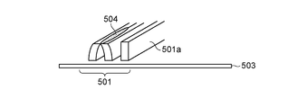
- ⁇ Minute droplets may be scattered when the ejection part of the imprint apparatus ejects the imprint material. As shown in FIG. 9, the scattered liquid droplets 504 adhere to the cured imprint material pattern 501 formed on the substrate 503, so that the pattern 501 collapses so that the convex portions 501 a of the pattern 501 approach each other. May occur.
- Patent Document 1 an imprint area is controlled so that a pattern is formed in an imprint area located on the upstream side of the airflow in the chamber before the imprint area located on the downstream side of the airflow.
- a printing device is described.
- Such pattern collapse may occur not only at the time of pattern formation as described in Patent Document 1, but also at the time of unloading the substrate. Alternatively, it is required to reduce the occurrence of pattern collapse even when liquid droplets scattered from the discharge part stay for some reason.
- An imprint apparatus is an imprint apparatus that forms a pattern of an imprint material on a plurality of regions of a substrate using a mold, includes an ejection port, and the imprint material passes through the ejection port.
- a discharge unit that discharges the substrate, a stage that moves while holding the substrate, and a control unit that controls the movement of the stage, wherein the control unit includes the first region in the plurality of regions.
- the first region does not pass the facing position facing the ejection port; and And after a predetermined time has elapsed since the discharge unit discharged the imprint material last to the substrate in a state where an air flow along the substrate was generated at a position facing the discharge port, putter And controlling the movement of the stage so that the passing position opposite to the forming region of the.
- FIG. 1A is a diagram illustrating a configuration of an imprint apparatus 100 according to the present embodiment.
- the imprint apparatus 100 forms a pattern of an imprint material on the substrate 103 using a mold 102.
- an axis parallel to the optical axis of the light 105a emitted from the light source 105, transmitted through the mold 102, and incident on the substrate 103 is defined as a Z axis (in this embodiment, the vertical direction).
- Two axes orthogonal to each other in a plane perpendicular to the Z axis are taken as an X axis and a Y axis.
- the stage 104 holds the substrate 103 via the holding unit 108.
- the holding unit 108 is connected to a vacuum pump (not shown) and sucks and holds the substrate 103 by a vacuum suction force.
- the stage 104 is moved on the surface plate 129 by the drive mechanism 113.
- the stage 104 is movable in the X-axis, Y-axis, Z-axis directions, and the rotation directions ( ⁇ X, ⁇ Y, ⁇ Z) of each axis.
- the drive mechanism 113 is an actuator such as a linear motor or a pulse motor, for example.
- the forming mechanism 101 has a mold driving mechanism (not shown) for moving the mold 102 in the Z-axis direction and the mold holding unit 110 that holds the mold 102 by vacuum suction.
- a mold driving mechanism (not shown) for moving the mold 102 in the Z-axis direction and the mold holding unit 110 that holds the mold 102 by vacuum suction.
- the mold drive mechanism uses the mold drive mechanism to move the mold 102 in the Z-axis direction and the mold holding unit 110 that holds the mold 102 by vacuum suction.
- the mold drive mechanism the contact operation between the uncured imprint material 127 and the mold 102 and the separation operation of the mold 102 from the cured imprint material 127 are performed.
- a reverse pattern of the concavo-convex pattern formed on the pattern portion 102 a of the mold 102 is formed on the imprint material 127.
- a cylindrical space 101 a is formed at the center of the forming mechanism 101.
- the contact operation and the separation operation between the imprint material 127 and the mold 102 may be performed by the movement of only the stage 104 or a combination of the movement of the forming mechanism 101 and the stage 104.
- the direction of separation is, for example, a direction along the Z-axis direction.
- a pressure control unit (not shown) feeds and exhausts gas through the pipe 111, and controls the pressure in the space 101a surrounded by the glass plate 112 and the recess 102b of the mold 102.
- the pressure controller By causing the pressure of the space 101a to rise above the pressure in the imprint apparatus 100 by the pressure controller, the pattern portion 102a of the mold 102 is deformed into a convex shape in the direction of the substrate 103.
- the holding unit 108 and the mold holding unit 110 may hold each holding object using an electrostatic force instead of a vacuum adsorption force.
- the mold 102 includes a rectangular pattern portion 102a in which a concavo-convex pattern is formed at the center.
- a concave portion 102b is formed on the surface of the mold 102 on the side opposite to the pattern portion 102a and is dug by about 1 mm in the Z-axis direction. It has a recess 123 and a projection 124 provided in the pattern portion 102a, the recess and the digging depth are several tens to several hundreds nm, and the width of each of the recess 123 and the projection 124 is several nm to several tens of nm. Degree.
- the alignment system 116 detects marks (not shown) formed at the four corners of the pattern portion 102 a and marks (not shown) formed on the substrate 103. Based on the detection result, the control unit 126 acquires a relative position, a shape difference, and the like between each shot region of the substrate 103 and the pattern unit 102a.
- the shot area is a unit area of the underlying layer on which the pattern has already been formed, and is divided by a scribe line (not shown).
- One shot corresponds to a repetitive pattern formed using a reticle by an optical exposure apparatus.
- One shot area has a size of about 26 mm ⁇ 33 mm, for example.
- One or a plurality of patterns having a chip size desired by the user can be formed in one shot area.
- a material capable of transmitting the light 105a that can cure the imprint material 127 is used.
- examples thereof include quartz glass, silicate glass, glass such as calcium fluoride, magnesium fluoride, and acrylic glass, sapphire and gallium nitride, and resins such as polycarbonate, polystyrene, acrylic, and polypropylene. Alternatively, any laminated material of these materials may be used.
- the alignment system 107 detects an alignment mark (not shown) formed on the substrate 103 and a reference mark formed on the upper surface of the mark table 115. Based on the detection result, the control unit 126 determines the position of the substrate 103 with respect to the stage 104.
- the alignment system 116 detects marks (not shown) formed on the mold 102 and alignment marks on the substrate 103. The alignment system 116 is based on the mark formed on the mold 102 and the moire signal (interference fringe) generated by the alignment mark, and the positional deviation or shape difference between the shot area where the pattern of the imprint material 127 is formed and the pattern portion 102a. Ask for.
- the imaging unit 114 images the direction of the substrate 103 during the imprint operation, and observes how the imprint material 127 is filled in the recesses 123.
- the control unit 126 determines the presence / absence of particles between the mold 102 and the substrate 103 based on the imaging result of the imaging unit 114.
- the supply mechanism 125 supplies a gas for supplying the space between the mold 102 and the substrate 103. For example, helium gas is supplied as the gas. Thereby, the filling of the imprint material 127 into the concave portion 123 is promoted.
- the sensor 109 is an optical distance measuring sensor, and measures a position 109 a (surface position) in the Z-axis direction on the surface of the substrate 103.
- the discharge unit 106 includes a tank (not shown) that includes an uncured imprint material 127 and a nozzle 122 that discharges the imprint material 127.
- FIG. 1B is a view of the discharge unit 106 viewed from the ⁇ Z direction.
- the nozzle 122 discharges the imprint material 127 through a plurality of discharge ports 122a formed along the Y-axis direction.
- FIG. 1B illustrates the case where the discharge ports 122a are formed in only one row in the X-axis direction, a plurality of rows may be formed along the X-axis direction.
- the nozzle 122 discharges the imprint material 127a while scanning the substrate 103 along the X-axis direction at a position facing the discharge port 122a.
- the imprint material 127 a is supplied to the substrate 103 in a plurality of droplets or in a state of being wetted and spread on the substrate 103.
- the length of the nozzle 122 in the Y-axis direction is configured to be approximately equal to the length of one side of the shot area.
- the stage 104 reciprocates between the facing position facing the discharge port 122a and the position facing the mold 102 many times. Thereby, the imprint material 127 is applied to the substrate 103 and the pattern is formed on the applied imprint material 127 in sequence.
- Each component of the imprint apparatus 100 is accommodated in the chamber 118.
- a gas supply unit 120 and a gas recovery unit 121 are provided as an air conditioning mechanism inside the chamber 118.
- the gas supply unit 120 takes in gas in the atmosphere outside the chamber 118, removes chemical substances and dust contained in the gas taken in by the chemical filter and the particle filter, and supplies clean gas to the inside of the chamber 118.
- the gas recovery unit 121 sucks the gas using a vacuum pump or the like.
- the gas supply unit 120 and the gas recovery unit 121 generate an air flow 119 that flows from the + X direction to the ⁇ X direction inside the chamber 118.
- the direction of the air flow 119 may be an air flow flowing in another direction.
- the control unit 126 is connected to the forming mechanism 101, the light source 105, the discharge unit 106, the alignment system 107, the sensor 109, the drive mechanism 113, the imaging unit 114, the alignment system 116, and the storage unit 130.
- the storage unit 130 stores measurement results of various measuring devices, a pattern formation order determined by the control unit 126, and the like.
- the control unit 126 reads the program stored in the storage unit 130 and controls each component connected to the control unit 126 to execute the program.
- the control unit 126 includes an arithmetic processing device such as a CPU and MPU and a storage device such as a memory.
- the control unit 126 also has a function as a determination unit that determines the order of pattern formation on the plurality of shot regions of the substrate 103. That is, the arithmetic processing unit of the control unit 126 can perform arithmetic processing for determining the formation order.
- the movement of the stage 104 is controlled by sending a control signal to the drive mechanism 113 so that the determined formation order is obtained.
- the control unit 126 may be an assembly of separate control boards or a single control board.
- FIG. 2 is a diagram for explaining the operation of the transport mechanism (unloading unit) 200 for transporting the substrate 103.
- the transport mechanism 200 includes a hand 202 that holds the substrate 103, an arm 203 that can extend in the XY direction and the rotation direction of the hand 202, and a drive mechanism 201 that can move the arm 203 in the Z-axis direction.
- the transport mechanism 200 extracts the substrate 103 from the storage unit 204 in which a plurality of substrates 103 are stored, places the substrate 103 on the standby position 205a, loads the substrate 103 from the standby position 205a to the stage 104, and waits from the stage 104.
- the substrate 103 is carried out to 205b.
- Pattern formation order When the imprint material 127 is ejected from the nozzle 122, not only droplets that land on the substrate 103 but also mist-like minute droplets (mist) separated from the droplets are generated. A description will be given of the order in which the minute droplets adhere to the pattern of the imprint material 127 formed on the substrate 103 and the pattern formation order for reducing the collapse of the pattern of the imprint material 127 due to the adhesion.
- the pattern formation order according to the present embodiment is set in advance by the control unit 126, and the control unit 126 moves the stage 104 so as to execute the formation order.
- FIG. 3 is a view for explaining the pattern formation order according to the first embodiment.
- FIG. 3 shows how patterns are formed in the same row, that is, adjacent shot regions in the X-axis direction, among a plurality of shot regions (a plurality of regions) arranged two-dimensionally on the substrate 103.
- illustration of the above-mentioned recessed part 123 and the convex part 124 is abbreviate
- FIGS. 3D to 3F are views of the substrate 103 viewed from the ⁇ Y direction.
- FIG. 3 (c) and FIG. 3 (f) show the situation at the same time.
- the black shot area indicates a shot area where a pattern of the cured imprint material 127 is formed.
- FIGS. 3A and 3D show a state where the imprint material pattern has already been formed on the shot region 701.
- FIG. 3B and FIG. 3E show a state in which the nozzle 122 starts to discharge the imprint material 127 so as to be supplied to the shot region 702.
- the imprint material 127 is discharged while the stage 104 moves in the + X direction. Simultaneously with the discharge of the imprint material 127, a minute droplet 703 is also discharged.
- 3 (c) and 3 (f) show the state when the shot area 702 is opposed to the mold 102 and the pattern has been formed on the imprint material 127 supplied to the shot area 702.
- FIG. The droplet 703 drifts in the vicinity of the nozzle 122 until the transition from the state of FIG. 3B to the transition of FIG. However, since the shot region 701 in which the pattern is formed does not pass the facing position that faces the ejection port 122a, the droplet 703 is prevented from attaching to the shot region 701 in which the pattern of the imprint material 127 is formed. be able to.
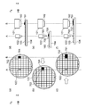
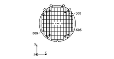
- FIG. 4 is a diagram showing another example of the pattern formation order for a plurality of shot regions.
- a pattern is formed in order from the shot area 505 at the lower right of the substrate 103 to the shot areas in the same row (first row).
- a pattern is formed in order from the bottom shot area 506 in the adjacent row (second row) to the second shot region. These may be repeated every time the column is changed, and the formation sequence may be such that the pattern is finally formed in the shot region 507.
- a pattern is formed in order from the shot area 505 at the lower right of the substrate 103 to the shot areas in the same row (first row).
- a pattern is sequentially formed from the uppermost shot area 508 in the adjacent row (second row) to the second shot region.
- the formation order may be such that patterns are sequentially formed in different rows in the order of reciprocation in the Y-axis direction, and the pattern is finally formed in the shot region 509.
- the first shot region (first region) and the second shot region (second region) are arranged in order from the facing position facing the discharge port 122b to the position facing the mold 102, the first A pattern is formed in the second shot area prior to the shot area.
- the first shot region is opposed to the ejection port 122b during the period from the formation of the imprint material 127 pattern in the first shot region to the formation of the pattern in the second shot region. Restrict (prohibit) the order of formation that passes through the position.
- FIGS. 10A to 10C are views of the substrate 103 viewed from the + Z direction
- FIGS. 10D to 10F are views of the substrate 103 viewed from the ⁇ Y direction.
- 10A and 10D, FIG. 10B and FIG. 10E, and FIG. 10C and FIG. 10F show the situation at the same time.
- the black shot area indicates a shot area where a pattern of the cured imprint material 127 is formed. If the pattern is formed in the shot area 501 first, the shot area 501 passes through the facing position facing the ejection port 122b during the movement for applying the imprint material 127 to the shot area 502. Small droplets 504 are likely to adhere to the shot region 501.
- the airflow below the discharge port 122b is preferably formed in a direction that does not include a component in a direction from the facing position facing the discharge port 122b to the position facing the mold 102. It is possible to further suppress the minute droplets 703 from adhering to the pattern formed on the substrate 103.
- the second embodiment is different from the first embodiment in that the control unit 126 does not set the pattern formation order as in the first embodiment, but the user of the imprint apparatus 100 can set the pattern formation order. Different. However, the control unit 126 confirms whether or not the droplet 703 is in a formation order that can prevent the droplet 703 from adhering to the pattern of the formed imprint material 127.
- the imprint apparatus 100 has a user interface for the user to set the pattern formation order.
- the user interface includes a display and is connected to the control unit 126.
- the storage unit 130 stores a program shown in the flowchart of FIG.
- the control unit 126 reads the program and confirms the pattern formation order.
- the storage unit 130 stores the types of molds 102 and the necessity of confirmation of the formation order of the respective molds 102 in association with each other.
- the mold 102 that requires confirmation of the formation order is, for example, a pattern in which the pitch between the concave portions 123 and the convex portions 124 is narrow, or a vertical length (a length in the Z-axis direction) than the horizontal length of the convex portions 124. Is twice or more.
- FIG. 5 is a flowchart showing a method for confirming the pattern formation order.
- the control unit 126 confirms the type of the mold 102 in which the mold 102 is carried into the imprint apparatus 100.
- the control unit 126 refers to the information stored in the storage unit 130 and determines whether or not the mold 102 carried in S ⁇ b> 601 is a mold that requires confirmation of the formation order.
- the process proceeds to S605.
- An imprint process is performed on each shot area of the substrate 103 in the pattern formation order set by the user via the user interface on the substrate 103 carried into the imprint apparatus 100.
- the pattern formation order may not be any of the formation orders described in the first embodiment.
- step S602 when the control unit 126 determines that the mold needs to be confirmed in the formation order (Yes), the process proceeds to S603, where the pattern formation order set by the user via the user interface is confirmed. In step S604, the control unit 126 determines whether the pattern formation order satisfies a predetermined condition.
- the predetermined condition is that the area where the pattern of the imprint material 127 is previously formed does not pass through the position facing the ejection unit 106b.
- the pattern is formed in advance in the shot area on the + X direction side of the two shot areas in the same row.
- the order shown in the first embodiment is a preferable formation order.
- control unit 126 determines that the predetermined condition is satisfied (Yes) in S604, the process proceeds to S605, and the imprint is performed in the pattern formation order set by the user via the user interface on the substrate 103 carried in. Process.
- the control unit 126 determines in S604 that the predetermined condition is not satisfied (No), that is, when it is determined that the region where the pattern of the imprint material 127 is formed first passes the position facing the ejection unit 106b. Advances to S606.
- the control unit 126 notifies the user of an error.
- the above-described interface may be notified that the formation order is inappropriate, or may be notified by turning on a predetermined light source or emitting a predetermined sound.
- the program shown in the flowchart of FIG. 4 is terminated without performing the imprint process on the substrate 103.
- an error may be notified in S606 and a display prompting the user to reset the pattern formation order that satisfies the above-described predetermined conditions may be performed.
- a recommended pattern formation order that satisfies the above-described predetermined conditions may be stored in the storage unit 130 in advance, and after an error is notified in S606, the imprint process may be performed in the recommended pattern formation order.
- the first shot region passes through the facing position facing the ejection port 122b during the period from the formation of the pattern of the imprint material 127 in the first shot region to the formation of the pattern in the second shot region. Regulate the order of formation. As a result, it is possible to suppress droplets floating at a position facing the ejection port 122b from adhering to the pattern of the cured imprint material 127, and to reduce the occurrence of pattern collapse of the imprint material formed on the substrate 103. can do.
- the airflow below the discharge port 122b is preferably formed in a direction that does not include a component in a direction from the facing position facing the discharge port 122b to the position facing the mold 102. It is possible to further suppress the minute droplets 703 from adhering to the pattern formed on the substrate 103.
- the stage 104 moves from the position P of the substrate stage 104 when the pattern is finally formed on the shot area to the position P ′ where the substrate 103 can be unloaded by the transport mechanism 200.
- the position P and the position P ′ are, for example, the center position of the stage 104.
- FIG. 6 is a view showing a carry-out path of the substrate 103, and is a view of the stage 104 and the transport mechanism 200 as seen from the + Z direction.
- the same components as those already described are denoted by the same reference numerals, and detailed description thereof is omitted.
- the transport mechanism 200 is provided on the discharge unit 106 side with respect to the mold holding unit 110.
- the shot area where the pattern is formed passes through the position facing the ejection port 122b. End up.
- the minute droplet 703 generated when the nozzle 122 ejects the droplet remains in the position facing the ejection port 122b even when the substrate 103 is carried out, the minute droplet 703 is formed. There is a risk that the pattern collapses due to adhesion to the pattern.
- the control unit 126 sets the carry-out route of the substrate 103 as a bypass route.
- the detour path refers to a plurality of shot areas in which the pattern is formed between the discharge port 122b and the stage 104 after the pattern of the imprint material 127 is formed on the substrate 103 until the stage 104 is moved to the transport mechanism 200. This route does not pass through the opposite position. Further, it may be a route that is not the shortest route from the position P to the position P ′.
- a route 902 is an example of a detour route.
- the path 902 is a path for moving the stage 104 so that the substrate 103 is positioned on the ⁇ Y direction side with respect to the nozzle 122 and then moving to the transport mechanism 200.
- the imprint material pattern formed on the substrate 103 is suppressed by preventing the liquid droplets floating in the position facing the discharge ports 122b from adhering to the cured imprint material 127 pattern. The occurrence of falling can be reduced.
- the substrate 103 can be taken out using the detour route only when the control unit 126 determines that it is necessary according to the type of the mold 102.
- the airflow below the discharge port 122b is preferably formed in a direction that does not include a component in a direction from the position facing the discharge port 122b toward the position facing the mold 102 when the pattern is formed. It is possible to further suppress the minute droplets 703 from adhering to the pattern formed on the substrate 103.
- FIG. 7A is a view of the periphery of the stage 104 as viewed from the + Z direction
- FIG. 7B is a view of the periphery of the nozzle 122 as viewed from the ⁇ Y direction.
- the pattern formation on the shot region of the substrate 103 is performed so that the region where the pattern is formed first does not face the ejection port 122b.
- the movement of the stage 104 for applying the imprint material 127 and imprint processing may not be performed in the shortest distance.
- the control unit 126 controls the stage 104 so that the pattern formed on the substrate 103 moves to a position facing the nozzle 122 after at least a predetermined time T has elapsed since the nozzle 122 finally ejected the imprint material. To do.
- the length of the discharge region of the nozzle 122 in the direction of the air flow 119 is L
- the gap from the nozzle 122 to the object facing the nozzle 122 is G
- the reference gap from the nozzle 122 to the stage 104 Is G0.
- the length of the discharge region of the nozzle 122 is the length from end to end of the discharge port 122b used for applying the imprint material 127 among the plurality of discharge ports 122b arranged in the Y-axis direction.
- the predetermined time T is determined by the following formula (1) or formula (2) according to the gap G, for example.
- T L / V 0 (G> G 0 )
- T L / V 1 (G ⁇ G 0 ) (2)
- Formula (1) is a case where G> G0. For example, this is a case where the stage 104 does not face the discharge port 122b. At this time, the flow velocity of the air flow 119 below the nozzle 122 is V0.
- Formula (2) is a case where G ⁇ G0.
- this is a case where the stage 104 faces the discharge port 122b.
- This is a case where the substrate stage 104 is moving in a direction closer to the nozzle 122 than in the normal state.
- the flow velocity of the airflow below the nozzle 122 is V1.
- the reference gap G 0 is adjusted to about several hundred ⁇ m to 1 mm.
- V 0 ⁇ 0 may be set. .
- the time adjustment is performed by temporarily stopping the movement of the stage 104 along the XY plane during a period from when the imprint material 127 is finally discharged onto the substrate 103 to when a predetermined time T elapses. .
- the stage 104 may be moved along a detour route such as the route 1002.
- the stage 104 can be controlled so that the pattern formed on the substrate 103 moves to a position facing the discharge port 122b after the predetermined time T has elapsed.
- the stage 104 may be moved in the + X direction with respect to the nozzle 122 as in the path 1003.
- the object facing the nozzle 122 becomes the surface plate 129 instead of the substrate stage 104.
- the gap G to the object until the nozzle 122 faces can be set such that gap G> reference gap G0.
- the predetermined time T can be shortened by increasing the distance to the object until the discharge port 122b opposes.
- the distance to the object until the discharge port 122b faces may be increased. If the predetermined time T has elapsed, when the predetermined time T elapses, the minute droplets 703 are exhausted along the airflow 119 from a position facing the discharge port 122b. Therefore, even if the formed pattern passes under the discharge port 122b, the pattern collapse hardly occurs.
- the direction of the airflow 119 is not limited to this.
- An air flow along the substrate 103 may be generated at a position facing the discharge port 122b so that the minute droplets 703 are not accumulated.
- the imprint apparatus 100 is configured such that the ejection unit 106 can be retracted. Specifically, based on an instruction from the control unit (moving unit) 106, a retreat position (second position) that is separated from the position (first position) when the ejection unit 106 applies the imprint material 127 in the + Z direction. The position can be moved.
- the controller 126 During the sequential formation of patterns for a plurality of shot areas on the substrate 103 or until the stage 104 is moved to the transport mechanism 200 after the imprint material 127 is finally discharged, the controller 126. Drafts the discharge unit 106 to the retreat position. While the ejection unit 106 is retracted to the retracted position, the stage 104 is controlled so that the region where the pattern of the imprint material 127 is formed passes through the position facing the ejection port 122b.
- minute droplets 703 are discharged along the airflow 119. Therefore, even if the formed pattern passes under the discharge port 122b, the pattern collapse hardly occurs. While the discharge unit 106 is retracted to the retracted position, gas may be temporarily supplied to a position facing the discharge port 122b to increase the exhaust force of the minute droplets 703.
- the airflow 119 may be formed by an airflow forming unit separately provided near the nozzle 122. .
- the air flow 119 may be formed by drawing the surrounding gas by moving the stage 104 in the horizontal direction (direction along the XY plane).
- the same surface plate (not shown) may be arranged around the substrate 103 on the stage 104.
- the coplanar plate is a plate material arranged so that the height of the surface thereof is substantially the same as that of the substrate 103.
- the pattern of the cured product formed using the imprint apparatus or the pattern of the cured product remaining after developing the substrate on which the latent image pattern is formed using another lithographic apparatus is permanently attached to at least a part of various articles. Or it is temporarily used when manufacturing various articles
- the article is an electric circuit element, an optical element, a MEMS, a recording element, a sensor, or a mold.
- Examples of electric circuit elements include volatile or nonvolatile semiconductor memories such as DRAM, SRAM, flash memory, and MRAM, and semiconductor elements such as LSI, CCD, image sensor, and FPGA.
- Examples of the mold include an imprint mold.
- the pattern of the cured product is used as it is as at least a part of the above-mentioned article or temporarily used as a resist mask. After etching or ion implantation is performed in the substrate processing step, the resist mask is removed.
- the processing steps may further include other well-known processing steps (development, oxidation, film formation, vapor deposition, planarization, resist stripping, dicing, bonding, packaging, etc.).
- FIG. 8 is a diagram illustrating an example of a method for manufacturing an article using an imprint apparatus. In FIG. 8, only a region where a pattern is formed by one stamping operation is shown, and other portions of the substrate 103 are omitted. 8A to 8D show the contents of the above-described imprint process (imprint method).
- the supply unit 207 supplies the imprint material 127 to the surface of the substrate 103 where the workpiece 103z such as an insulator is formed on the surface of the base material 2a.
- the workpiece 103z such as an insulator is formed on the surface of the base material 2a.
- the surface of the mold 102 on which the concave / convex pattern is formed and the imprint material 127 on the substrate 103 are opposed to each other.
- the mold 102 is lowered and the mold 102 and the imprint material 127 are brought into contact with each other.
- a predetermined pressure may be applied to the mold 102.
- the imprint material 127 is filled in a gap between the mold 102 and the workpiece 103z. In this state, when the irradiation unit 3 irradiates the light 105a through the mold 102, the imprint material 127 is cured.
- a pattern of a cured product of the imprint material 127 is formed on the substrate 103 as shown in FIG. 8D.
- the pattern of the cured product has a shape in which the concave portion of the mold corresponds to the convex portion of the cured product, and the concave portion of the mold corresponds to the convex portion of the cured product. That is, a reverse pattern of the concave / convex pattern of the mold 102 is formed on the imprint material 127.
- 8A to 8D are repeated until the pattern of the cured product is formed on all the pattern formation target regions on the substrate 103.
- a pattern of a cured product may be formed in all regions on the substrate 103 by a single stamping operation.
Landscapes
- Physics & Mathematics (AREA)
- General Physics & Mathematics (AREA)
- Engineering & Computer Science (AREA)
- Mechanical Engineering (AREA)
- Health & Medical Sciences (AREA)
- Environmental & Geological Engineering (AREA)
- Epidemiology (AREA)
- Public Health (AREA)
- Shaping Of Tube Ends By Bending Or Straightening (AREA)
- Exposure Of Semiconductors, Excluding Electron Or Ion Beam Exposure (AREA)
Priority Applications (3)
| Application Number | Priority Date | Filing Date | Title |
|---|---|---|---|
| CN201780077125.6A CN110383423B (zh) | 2016-12-13 | 2017-12-11 | 制品的压印设备和方法 |
| KR1020197019558A KR102239964B1 (ko) | 2016-12-13 | 2017-12-11 | 임프린트 장치, 및 물품의 제조 방법 |
| US16/435,147 US11524429B2 (en) | 2016-12-13 | 2019-06-07 | Imprinting apparatus and method of manufacturing product |
Applications Claiming Priority (2)
| Application Number | Priority Date | Filing Date | Title |
|---|---|---|---|
| JP2016-241685 | 2016-12-13 | ||
| JP2016241685A JP6821414B2 (ja) | 2016-12-13 | 2016-12-13 | インプリント装置、及び物品の製造方法 |
Related Child Applications (1)
| Application Number | Title | Priority Date | Filing Date |
|---|---|---|---|
| US16/435,147 Continuation US11524429B2 (en) | 2016-12-13 | 2019-06-07 | Imprinting apparatus and method of manufacturing product |
Publications (1)
| Publication Number | Publication Date |
|---|---|
| WO2018110517A1 true WO2018110517A1 (ja) | 2018-06-21 |
Family
ID=62558597
Family Applications (1)
| Application Number | Title | Priority Date | Filing Date |
|---|---|---|---|
| PCT/JP2017/044432 Ceased WO2018110517A1 (ja) | 2016-12-13 | 2017-12-11 | インプリント装置、及び物品の製造方法 |
Country Status (6)
| Country | Link |
|---|---|
| US (1) | US11524429B2 (https=) |
| JP (1) | JP6821414B2 (https=) |
| KR (1) | KR102239964B1 (https=) |
| CN (1) | CN110383423B (https=) |
| TW (1) | TWI659453B (https=) |
| WO (1) | WO2018110517A1 (https=) |
Families Citing this family (2)
| Publication number | Priority date | Publication date | Assignee | Title |
|---|---|---|---|---|
| JP7118712B2 (ja) * | 2018-04-13 | 2022-08-16 | キヤノン株式会社 | インプリント装置、インプリント方法、および物品の製造方法 |
| JP7149870B2 (ja) * | 2019-02-08 | 2022-10-07 | キヤノン株式会社 | インプリント装置および物品製造方法 |
Citations (5)
| Publication number | Priority date | Publication date | Assignee | Title |
|---|---|---|---|---|
| JP2015233100A (ja) * | 2014-06-10 | 2015-12-24 | キヤノン株式会社 | インプリント装置、および物品製造方法 |
| WO2016052345A1 (ja) * | 2014-10-01 | 2016-04-07 | 大日本印刷株式会社 | インプリント装置、インプリント方法およびインプリント装置の制御方法 |
| JP2016051862A (ja) * | 2014-09-02 | 2016-04-11 | キヤノン株式会社 | インプリント装置、および物品の製造方法 |
| JP2016111062A (ja) * | 2014-12-02 | 2016-06-20 | キヤノン株式会社 | インプリント装置及び物品の製造方法 |
| JP2016134608A (ja) * | 2015-01-22 | 2016-07-25 | キヤノン株式会社 | インプリント装置及び方法、並びに物品の製造方法 |
Family Cites Families (10)
| Publication number | Priority date | Publication date | Assignee | Title |
|---|---|---|---|---|
| JP2010080630A (ja) * | 2008-09-25 | 2010-04-08 | Canon Inc | 押印装置および物品の製造方法 |
| JP5697345B2 (ja) * | 2010-02-17 | 2015-04-08 | キヤノン株式会社 | インプリント装置、及び物品の製造方法 |
| JP5850717B2 (ja) * | 2010-12-02 | 2016-02-03 | キヤノン株式会社 | インプリント装置、及びそれを用いた物品の製造方法 |
| JP6180131B2 (ja) * | 2012-03-19 | 2017-08-16 | キヤノン株式会社 | インプリント装置、それを用いた物品の製造方法 |
| WO2015068215A1 (ja) * | 2013-11-06 | 2015-05-14 | キヤノン株式会社 | インプリント用型のパターンの決定方法、インプリント方法及び装置 |
| JP2015231036A (ja) * | 2014-06-06 | 2015-12-21 | キヤノン株式会社 | リソグラフィ装置、および物品製造方法 |
| JP2016025230A (ja) * | 2014-07-22 | 2016-02-08 | キヤノン株式会社 | インプリント方法、インプリント装置、および物品の製造方法 |
| JP6450105B2 (ja) * | 2014-07-31 | 2019-01-09 | キヤノン株式会社 | インプリント装置及び物品製造方法 |
| JP6429573B2 (ja) * | 2014-10-03 | 2018-11-28 | キヤノン株式会社 | インプリント装置、インプリント方法および物品製造方法 |
| US20160288378A1 (en) * | 2015-04-03 | 2016-10-06 | Canon Kabushiki Kaisha | Imprint material discharging device |
-
2016
- 2016-12-13 JP JP2016241685A patent/JP6821414B2/ja active Active
-
2017
- 2017-12-11 WO PCT/JP2017/044432 patent/WO2018110517A1/ja not_active Ceased
- 2017-12-11 KR KR1020197019558A patent/KR102239964B1/ko active Active
- 2017-12-11 CN CN201780077125.6A patent/CN110383423B/zh active Active
- 2017-12-12 TW TW106143493A patent/TWI659453B/zh active
-
2019
- 2019-06-07 US US16/435,147 patent/US11524429B2/en active Active
Patent Citations (5)
| Publication number | Priority date | Publication date | Assignee | Title |
|---|---|---|---|---|
| JP2015233100A (ja) * | 2014-06-10 | 2015-12-24 | キヤノン株式会社 | インプリント装置、および物品製造方法 |
| JP2016051862A (ja) * | 2014-09-02 | 2016-04-11 | キヤノン株式会社 | インプリント装置、および物品の製造方法 |
| WO2016052345A1 (ja) * | 2014-10-01 | 2016-04-07 | 大日本印刷株式会社 | インプリント装置、インプリント方法およびインプリント装置の制御方法 |
| JP2016111062A (ja) * | 2014-12-02 | 2016-06-20 | キヤノン株式会社 | インプリント装置及び物品の製造方法 |
| JP2016134608A (ja) * | 2015-01-22 | 2016-07-25 | キヤノン株式会社 | インプリント装置及び方法、並びに物品の製造方法 |
Also Published As
| Publication number | Publication date |
|---|---|
| KR20190094396A (ko) | 2019-08-13 |
| KR102239964B1 (ko) | 2021-04-14 |
| JP2018098366A (ja) | 2018-06-21 |
| CN110383423A (zh) | 2019-10-25 |
| US20190291309A1 (en) | 2019-09-26 |
| CN110383423B (zh) | 2023-06-30 |
| TW201822252A (zh) | 2018-06-16 |
| US11524429B2 (en) | 2022-12-13 |
| TWI659453B (zh) | 2019-05-11 |
| JP6821414B2 (ja) | 2021-01-27 |
Similar Documents
| Publication | Publication Date | Title |
|---|---|---|
| JP6611450B2 (ja) | インプリント装置、インプリント方法、及び物品の製造方法 | |
| KR102507668B1 (ko) | 임프린트 장치, 임프린트 방법 및 물품 제조 방법 | |
| JP6300459B2 (ja) | インプリント装置およびインプリント方法、それを用いた物品の製造方法 | |
| US11556054B2 (en) | Forming apparatus, determination method, and article manufacturing method | |
| CN114127911A (zh) | 制造物品的平坦化过程、设备和方法 | |
| JP6714378B2 (ja) | インプリント装置、及び物品の製造方法 | |
| KR20190062202A (ko) | 정보 처리 장치, 컴퓨터 프로그램, 리소그래피 장치, 리소그래피 시스템 및 물품의 제조 방법 | |
| US20250065381A1 (en) | Particle removal method, particle removal apparatus, and method for manufacturing article | |
| JP2020145383A (ja) | インプリント装置の制御方法、インプリント装置、および物品製造方法 | |
| WO2018110517A1 (ja) | インプリント装置、及び物品の製造方法 | |
| US20260061691A1 (en) | Imprint device, imprint method, storage medium, and article manufacturing method | |
| KR102317410B1 (ko) | 임프린트 장치, 임프린트 방법, 임프린트재의 배치 패턴의 결정 방법 및 물품의 제조 방법 | |
| KR20180048323A (ko) | 임프린트 장치, 임프린트 방법 및 물품의 제조 방법 | |
| JP2018098366A5 (https=) | ||
| JP7710313B2 (ja) | モールド、インプリント装置、および物品の製造方法 | |
| KR20190124643A (ko) | 몰드를 사용해서 기판 상의 조성물을 성형하는 성형 장치, 성형 방법 및 물품의 제조 방법 | |
| KR102537179B1 (ko) | 임프린트 장치, 임프린트 방법 및 물품의 제조 방법 | |
| KR102316054B1 (ko) | 거푸집, 임프린트 장치, 및 물품의 제조 방법 | |
| JP2020185558A (ja) | 観察装置、観察方法、成形装置、および、物品の製造方法 | |
| WO2016052345A1 (ja) | インプリント装置、インプリント方法およびインプリント装置の制御方法 | |
| KR102899620B1 (ko) | 성형 장치, 성형 방법, 및 물품 제조 방법 | |
| JP7693415B2 (ja) | 液体吐出装置、液体吐出方法、成形装置及び物品の製造方法 | |
| KR102590769B1 (ko) | 반송 장치, 반송 방법, 리소그래피 장치, 리소그래피 시스템, 및 물품 제조 방법 | |
| JP2022091479A (ja) | 形成装置、形成方法及び物品の製造方法 | |
| JP2015177123A (ja) | インプリント装置、および物品の製造方法 |
Legal Events
| Date | Code | Title | Description |
|---|---|---|---|
| 121 | Ep: the epo has been informed by wipo that ep was designated in this application |
Ref document number: 17880113 Country of ref document: EP Kind code of ref document: A1 |
|
| NENP | Non-entry into the national phase |
Ref country code: DE |
|
| ENP | Entry into the national phase |
Ref document number: 20197019558 Country of ref document: KR Kind code of ref document: A |
|
| 122 | Ep: pct application non-entry in european phase |
Ref document number: 17880113 Country of ref document: EP Kind code of ref document: A1 |