WO2018106033A2 - Purificateur d'air à direction de vent réglable - Google Patents
Purificateur d'air à direction de vent réglable Download PDFInfo
- Publication number
- WO2018106033A2 WO2018106033A2 PCT/KR2017/014269 KR2017014269W WO2018106033A2 WO 2018106033 A2 WO2018106033 A2 WO 2018106033A2 KR 2017014269 W KR2017014269 W KR 2017014269W WO 2018106033 A2 WO2018106033 A2 WO 2018106033A2
- Authority
- WO
- WIPO (PCT)
- Prior art keywords
- air
- guide
- housing
- discharge port
- air guide
- Prior art date
Links
Images


Classifications
-
- F—MECHANICAL ENGINEERING; LIGHTING; HEATING; WEAPONS; BLASTING
- F24—HEATING; RANGES; VENTILATING
- F24F—AIR-CONDITIONING; AIR-HUMIDIFICATION; VENTILATION; USE OF AIR CURRENTS FOR SCREENING
- F24F8/00—Treatment, e.g. purification, of air supplied to human living or working spaces otherwise than by heating, cooling, humidifying or drying
- F24F8/80—Self-contained air purifiers
-
- F—MECHANICAL ENGINEERING; LIGHTING; HEATING; WEAPONS; BLASTING
- F24—HEATING; RANGES; VENTILATING
- F24F—AIR-CONDITIONING; AIR-HUMIDIFICATION; VENTILATION; USE OF AIR CURRENTS FOR SCREENING
- F24F13/00—Details common to, or for air-conditioning, air-humidification, ventilation or use of air currents for screening
- F24F13/02—Ducting arrangements
- F24F13/06—Outlets for directing or distributing air into rooms or spaces, e.g. ceiling air diffuser
- F24F13/065—Outlets for directing or distributing air into rooms or spaces, e.g. ceiling air diffuser formed as cylindrical or spherical bodies which are rotatable
-
- F—MECHANICAL ENGINEERING; LIGHTING; HEATING; WEAPONS; BLASTING
- F24—HEATING; RANGES; VENTILATING
- F24F—AIR-CONDITIONING; AIR-HUMIDIFICATION; VENTILATION; USE OF AIR CURRENTS FOR SCREENING
- F24F13/00—Details common to, or for air-conditioning, air-humidification, ventilation or use of air currents for screening
- F24F13/20—Casings or covers
-
- F—MECHANICAL ENGINEERING; LIGHTING; HEATING; WEAPONS; BLASTING
- F24—HEATING; RANGES; VENTILATING
- F24F—AIR-CONDITIONING; AIR-HUMIDIFICATION; VENTILATION; USE OF AIR CURRENTS FOR SCREENING
- F24F3/00—Air-conditioning systems in which conditioned primary air is supplied from one or more central stations to distributing units in the rooms or spaces where it may receive secondary treatment; Apparatus specially designed for such systems
- F24F3/12—Air-conditioning systems in which conditioned primary air is supplied from one or more central stations to distributing units in the rooms or spaces where it may receive secondary treatment; Apparatus specially designed for such systems characterised by the treatment of the air otherwise than by heating and cooling
- F24F3/14—Air-conditioning systems in which conditioned primary air is supplied from one or more central stations to distributing units in the rooms or spaces where it may receive secondary treatment; Apparatus specially designed for such systems characterised by the treatment of the air otherwise than by heating and cooling by humidification; by dehumidification
-
- F—MECHANICAL ENGINEERING; LIGHTING; HEATING; WEAPONS; BLASTING
- F24—HEATING; RANGES; VENTILATING
- F24F—AIR-CONDITIONING; AIR-HUMIDIFICATION; VENTILATION; USE OF AIR CURRENTS FOR SCREENING
- F24F8/00—Treatment, e.g. purification, of air supplied to human living or working spaces otherwise than by heating, cooling, humidifying or drying
- F24F8/10—Treatment, e.g. purification, of air supplied to human living or working spaces otherwise than by heating, cooling, humidifying or drying by separation, e.g. by filtering
- F24F8/117—Treatment, e.g. purification, of air supplied to human living or working spaces otherwise than by heating, cooling, humidifying or drying by separation, e.g. by filtering using wet filtering
-
- F—MECHANICAL ENGINEERING; LIGHTING; HEATING; WEAPONS; BLASTING
- F24—HEATING; RANGES; VENTILATING
- F24F—AIR-CONDITIONING; AIR-HUMIDIFICATION; VENTILATION; USE OF AIR CURRENTS FOR SCREENING
- F24F8/00—Treatment, e.g. purification, of air supplied to human living or working spaces otherwise than by heating, cooling, humidifying or drying
- F24F8/10—Treatment, e.g. purification, of air supplied to human living or working spaces otherwise than by heating, cooling, humidifying or drying by separation, e.g. by filtering
- F24F8/108—Treatment, e.g. purification, of air supplied to human living or working spaces otherwise than by heating, cooling, humidifying or drying by separation, e.g. by filtering using dry filter elements
-
- F—MECHANICAL ENGINEERING; LIGHTING; HEATING; WEAPONS; BLASTING
- F24—HEATING; RANGES; VENTILATING
- F24F—AIR-CONDITIONING; AIR-HUMIDIFICATION; VENTILATION; USE OF AIR CURRENTS FOR SCREENING
- F24F8/00—Treatment, e.g. purification, of air supplied to human living or working spaces otherwise than by heating, cooling, humidifying or drying
- F24F8/20—Treatment, e.g. purification, of air supplied to human living or working spaces otherwise than by heating, cooling, humidifying or drying by sterilisation
-
- F—MECHANICAL ENGINEERING; LIGHTING; HEATING; WEAPONS; BLASTING
- F24—HEATING; RANGES; VENTILATING
- F24F—AIR-CONDITIONING; AIR-HUMIDIFICATION; VENTILATION; USE OF AIR CURRENTS FOR SCREENING
- F24F8/00—Treatment, e.g. purification, of air supplied to human living or working spaces otherwise than by heating, cooling, humidifying or drying
- F24F8/50—Treatment, e.g. purification, of air supplied to human living or working spaces otherwise than by heating, cooling, humidifying or drying by odorisation
-
- Y—GENERAL TAGGING OF NEW TECHNOLOGICAL DEVELOPMENTS; GENERAL TAGGING OF CROSS-SECTIONAL TECHNOLOGIES SPANNING OVER SEVERAL SECTIONS OF THE IPC; TECHNICAL SUBJECTS COVERED BY FORMER USPC CROSS-REFERENCE ART COLLECTIONS [XRACs] AND DIGESTS
- Y02—TECHNOLOGIES OR APPLICATIONS FOR MITIGATION OR ADAPTATION AGAINST CLIMATE CHANGE
- Y02A—TECHNOLOGIES FOR ADAPTATION TO CLIMATE CHANGE
- Y02A50/00—TECHNOLOGIES FOR ADAPTATION TO CLIMATE CHANGE in human health protection, e.g. against extreme weather
- Y02A50/20—Air quality improvement or preservation, e.g. vehicle emission control or emission reduction by using catalytic converters
Definitions
- the present invention relates to an air purifier capable of adjusting the wind direction.
- the annular air discharge port may be employed in consideration of product design, or may be used to discharge the discharged air in a tornado form.
- this annular air discharge port has a disadvantage in that it is not easy to control the wind direction in structure.
- the product having the annular air outlet according to the prior art has a structure in which the wind direction control of the annular air outlet is impossible.
- Korean Patent Laid-Open Publication Nos. 10-2014-0093158 and 10-2015-0092067 disclose an air conditioner having an annular air discharge port, and Korean Patent Laid-Open Publication Nos. 10-2014-0093158 and 10-2015-0092067.
- the air conditioner disclosed in Fig. 1 is a structure in which the wind direction conversion of the annular air outlet is impossible.
- an object of the present invention is to provide a wind direction adjustable air purifier that can adjust the wind direction of the annular air discharge port.
- the present invention comprises a housing having an air outlet on one surface; An air guide having a front end disposed at the center of the air discharge port so that the air discharge port is annular, and a rear end extending in the other surface direction of the housing; And a rotation guide rotatably coupled to the circumferential direction of the air discharge port inside the housing and supporting the air guide on the housing, wherein the air guide is inclined with respect to the air discharge direction of the air discharge port. It provides a wind direction adjustable air purifier coupled to the rotation guide to be rotatable in the direction.
- the present invention is a housing; An annular air outlet provided at the front of the housing; And an air guide having a front end disposed in the center of the air discharge port so that the air discharge port is annular, and a rear end extending in a back direction of the housing and having a hollow penetrating in the rear direction from the front of the housing.
- the air guide is provided with a wind direction adjustable air purifier rotatable in a direction inclined with respect to the air discharge direction of the air discharge port.
- the present invention provides a housing comprising: a housing; A blowing fan provided inside the housing; An air discharge port formed on one surface of the housing; An air guide for distal end of the air discharge port so that the air discharge port is annular, and a rear end thereof extends toward the other surface of the housing to guide air flowing by the blower fan to the air discharge port; And a wind direction control unit coupled to the inside of the housing in a circumferential direction of the air guide and changing a discharge direction of the air discharged from the air discharge port according to the rotational position.
- the wind direction control unit may be disposed on the flow path of the air spaced apart from the air guide toward the outer circumferential surface of the air guide and may include an air barrier film to rotate in the circumferential direction of the air guide.
- the air barrier layer may be configured to adjust an area.
- the wind direction control unit, the plurality of deflection disposed in the air discharge port and the one end is deflected in one direction based on the discharge direction of the air discharged from the air discharge port and rotatable in the circumferential direction of the air discharge port It may include a blade.
- FIG. 1 is a front perspective view of an air cleaner according to a first embodiment and a second embodiment of the present invention.
- FIG. 2 is a rear perspective view of the air cleaner shown in FIG. 1.
- 3 to 15 are diagrams related to the first embodiment of the present invention.
- FIG. 3 is a side cross-sectional view of the air cleaner shown in FIG. 1.
- FIG. 4 is a side cross-sectional view when the air cleaner shown in FIG. 1 discharges air to the top discharge port.
- FIG. 5 is a side cross-sectional view when the air cleaner shown in FIG. 1 discharges air to an annular air discharge port.
- FIG. 6 is a side cross-sectional view when the air cleaner shown in FIG. 1 simultaneously discharges air to an annular air outlet and an upper outlet.
- 7 (a) and 7 (b) is an operation state diagram showing the wind direction control operation of the annular air discharge port provided in the air cleaner shown in FIG.
- FIG. 8 is a perspective view illustrating an assembly structure of an air guide, a rotation guide, and a rotational restriction included in the air cleaner shown in FIG. 1.
- FIG. 9 is an exploded perspective view illustrating the exploded guide and the rotational restriction part shown in FIG. 8.
- FIG. 10 is an exploded perspective view of the air guide and the rotation guide shown in FIG.
- FIG. 11 is a perspective view illustrating a state in which the air guide shown in FIG. 8 is rotated in the rotation guide.
- FIG. 12 is a cross-sectional perspective view of an upper portion of the air cleaner illustrated in FIG. 1.
- FIG. 13 is a side cross-sectional view illustrating an operation in which an air guide included in the air cleaner shown in FIG. 1 rotates in a rotation guide.
- FIG. 14 is a perspective view of a light emitting display unit included in an air cleaner according to another embodiment of the present invention.
- FIG. 15 is a front view illustrating an operating state of the light emitting display unit illustrated in FIG. 14.
- 16 to 29 are views related to the second embodiment of the present invention.
- FIG. 16 is a side cross-sectional view of the air cleaner shown in FIG. 1.
- 17 is a side cross-sectional view when the air cleaner shown in FIG. 1 discharges air to the upper discharge port.
- FIG. 18 is a side cross-sectional view when the air cleaner shown in FIG. 1 discharges air to an annular air outlet.
- 19 is a side cross-sectional view when the air cleaner shown in FIG. 1 simultaneously discharges air to an annular air outlet and an upper outlet.
- FIG. 20 is a perspective view illustrating an assembly structure of an air guide, a wind direction control unit, and a rotational restraint included in the air cleaner shown in FIG. 1.
- FIG. 21 is an exploded perspective view illustrating an exploded view of the wind direction control unit and the rotational restrictor illustrated in FIG. 20.
- FIG. 22 is an exploded perspective view illustrating the air guide and the wind direction control unit illustrated in FIG. 21.
- FIG. 23 is a perspective view of the wind direction control unit.
- 25 is a side cross-sectional view showing a driving unit for automatically rotating the wind direction control unit.
- FIG. 26 is a perspective view illustrating another embodiment of the air barrier membrane included in the wind direction control unit.
- FIG. 27 is a perspective view of the wind direction control unit included in the air cleaner according to another embodiment of the present invention.
- FIG. 28 is a cross-sectional view of the wind direction control unit shown in FIG. 27.
- FIG. 29 is a side cross-sectional view of the air cleaner having the wind direction control unit illustrated in FIG. 27.
- the air direction adjustable air purifier of the present invention includes two embodiments, and is divided into a first embodiment and a second embodiment.
- 1 and 2 show the shape of the outer surface common to both the first embodiment and the second embodiment
- Figures 3 to 15 show a view related to the first embodiment of the present invention
- Figure 16 29 to 29 show drawings related to the second embodiment of the present invention.
- reference numerals indicated in the first embodiment shown in FIGS. 3 to 15 and reference numerals indicated in the second embodiment shown in FIGS. 16 to 29 indicate different embodiments even though the same reference numerals are used. The following description is based on the assumption that they are different from each other.
- the air cleaner 100 according to an embodiment of the present invention is a housing 110, air guide 120, air hole 130, blowing fan 140, air purification
- the filter 150 and the flow path switching unit 160 may be included.
- the housing 110 constitutes an exterior of the air cleaner 100 according to an embodiment of the present invention, and may include an air inlet 111 through which external air is introduced into the housing 110, and the front surface is front. ) May be provided with an air discharge port 112, and may be provided with an upper discharge port 113 at an upper end thereof.
- the air discharge port 112 and the upper discharge port 113 may constitute a passage through which air sucked into the housing 110 is discharged to the outside of the housing 110.
- the air discharge port 112 may be formed in an annular shape due to the air guide 120 to be described later.
- the air intake 111 may be formed in the back (Back) of the housing 110, but is not limited thereto, and may be formed in at least one of the front, side and rear of the housing 110. It may be.
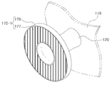
- the interior of the housing 110 may be provided with a partition 118 separating the air discharge port 112 and the upper discharge port 113.
- the partition wall 118 extends in the direction of the blower fan 140 from the upper discharge port 113, and the front discharge passage 115 and the blower connected to the air discharge port 112 from the blower fan 140 inside the housing 110.
- the upper discharge passage 116 connected to the upper discharge port 113 in the fan 140 may be formed.
- the air guide 120 is disposed in the housing 110, the front end portion is disposed in the center of the air discharge port 112 so that the air discharge port 112 is annular, and the rear end may extend in the other direction of the housing 110. have.
- the air guide 120 may be disposed in the front discharge passage 115 inside the housing 110 to guide the air flowing in the front discharge passage 115 to the air discharge port 112.
- the air guide 120 may be configured in a cylindrical shape having a hollow 122 penetrated in the rear direction from the front of the housing 110.
- the air guide 120 may be in communication with the air hole 130 to be described later to form a part of the hole penetrated from the front to the rear in the housing 110, but is not limited thereto.
- the rear end of 120 may be shielded by the partition wall 118.
- the partition wall 118 surrounds the upper half of the air guide 120 at intervals so as to guide the air flowing above the air guide 120 to the air discharge port 112 in the direction of the air discharge port 112.
- the enclosure 119 may be formed to extend.
- the air hole 130 is formed in the housing 110 and communicates with the hollow 122 of the air guide 120 may extend to the rear of the housing 110. To this end, the cylindrical or trumpet-shaped structure forming the air hole 130 may be formed across the upper discharge passage 116 in the interior of the housing (110).
- the hollow 122 of the air guide 120 and the air hole 130 is connected to the housing 110 may be a hole penetrating from the front to the rear of the housing 110.
- the air pressure around the air discharge port 112 is reduced, thereby, through the hollow 122 and the air hole 130 of the air guide 120
- the air at the rear of the housing 110 may join the air discharged from the air discharge port 112 and flow in front of the housing 110.
- the blowing fan 140 is provided inside the housing 110, and when the air is sucked in the air outside the housing 110 through the air inlet 111 during operation, the air is discharged to the air outlet 112 or the upper outlet 113. Can be discharged.
- the blowing fan 140 may be configured as a centrifugal fan disposed at the inlet side of the front discharge passage 115 and the top discharge passage 116 as shown in Figures 3 to 6, but is not limited thereto. The position and type of the blowing fan 140 may be changed.
- the air purification filter 150 may be provided between the air intake 111 and the blowing fan 140 to purify the air sucked into the air intake 111.
- the air purification filter 150 may include a prefilter, a deodorization filter, a sterilization filter, an activated carbon filter, a hepa filter, and the like.
- the air cleaner 100 may include a humidification filter for humidifying air or a dehumidification unit for dehumidifying the air between the air purifying filter 150 and the blowing fan 140. It may be.
- the flow path switching unit 160 may guide the air discharged from the blowing fan 140 to at least one of the air discharge port 112 and the upper discharge port 113.
- the flow path switching unit 160 may be provided inside the housing 110 to open and close the front discharge passage 115 and the top discharge passage 116.
- the flow path switching unit 160 may be configured to selectively open and close the front discharge passage 115 and the top discharge passage 116 by rotating as shown in FIGS. 2 to 6, but is not limited thereto. .
- the flow path switching unit 160 opens the front discharge passage 115 and closes the top discharge passage 116 as shown in FIG. 5, the air discharged by the blower fan 140 is annular air discharge port. Can be discharged to 112.
- the air cleaner 100 may be configured such that the air guide 120 is rotatable in a direction inclined with respect to the air discharge direction of the air discharge port 112.
- the air cleaner 100 may include a rotation guide 170 and a rotational restrictor 190.
- the rotation guide 170 may be coupled to the inside of the housing 110 and support the air guide 120 to the housing 110. That is, the rotation guide 170 may function as a medium for coupling the air guide 120 to the housing 110.
- the rotation guide 170 may be coupled to the housing 110 to be rotatable in the circumferential direction of the air discharge port 112.
- the air guide 120 coupled to the rotation guide 170 may also be rotated in the circumferential direction of the air discharge port 112 according to the rotation of the rotation guide 170.
- the air guide 120 may be coupled to the rotation guide 170 to be rotatable in a direction inclined with respect to the air discharge direction of the air discharge port 112.
- the air guide 120 may be coupled to the rotation guide 170 to be rotated up and down.
- the air guide 120 is also rotated in the circumferential direction of the air discharge port 112 in accordance with the rotation of the rotation guide 170, consequently the air guide
- the air guide 120 may be rotated left or right in the rotation guide 170 or may be rotated diagonally according to the arrangement position of the coupling portion 120 and the rotation guide 170.
- the air guide 120 can be rotated in a free direction within the range of the air discharge port (112).
- the front end portion of the air guide 120 is formed in a shape corresponding to the air outlet 112 and the annular rim portion 124 disposed in the air outlet 112, along the circumference of the air guide 120
- a plurality of guide blades 126 connected between the rim portion 124 and the air guide 120 may be provided.
- a plurality of guide blades 126 may be disposed in the annular air outlet 112, and the air discharged to the air outlet 112 is discharged into the space between the plurality of guide blades 126. .
- the guide blade 126 is formed to be inclined or curved along the circumferential direction of the air discharge port 112, as shown in Figure 7 and 8, the air discharged to the air discharge port 112 Can be discharged in the form of a whirlwind.
- the tornado type airflow has the advantage that the indoor air circulation performance is high because the reach is longer than the linear airflow.
- the rotation guide 170 may be composed of an annular frame 171, a rotating shaft member 172, a support frame 173 and a connecting frame 178.
- the annular frame 171 may surround the outer circumferential surface of the rim portion 124 of the air guide 120 in an airtight manner and may be rotatably coupled to the outer side of the air discharge port 112.
- the annular frame 171 may be rotatably coupled to the outer circumferential surface while maintaining airtightness on the front panel of the housing 110 forming the air outlet 112.
- airtightness may be maintained between the annular frame 171 and the rim 124 during the rotation of the air guide 120.
- the rim 124 is formed as a convex curved surface of the outer peripheral surface along the rotation direction of the air guide 120
- the annular frame 171 has a diameter of the inner surface at the maximum outer diameter of the rim 124 Is formed in accordance with, the outer circumferential surface of the rim portion 124 and the inner surface of the annular frame 171 may be in close contact with the rotation of the air guide 120.
- the curvature of the curved surface formed on the outer circumferential surface of the rim portion 124 may correspond to the curvature of the circle having a radius from the center of the air discharge port 112 to the inner surface of the annular frame 171, but is not limited thereto. It doesn't happen.
- the rotating shaft member 172 may rotatably couple the rim 124 to the annular frame 171.
- the rotating shaft member 172 may be provided in a pair at the opposite symmetrical position of the annular frame 171.
- the rotary shaft member 172 may fasten the rim 124 to the annular frame 171 such that the rim 124 and the air guide 120 can rotate about the annular frame 171. .
- the support frame 173 is a member which is rotatably supported in the circumferential direction of the air discharge port 112 by the partition wall 118 provided inside the housing 110 and is in contact with the rear end of the air guide 120.
- the rear end of the air guide 120 may slide on the surface of the support frame 173 in contact with the support frame 173.
- the contact portion of the support frame 173 and the rear end of the air guide 120 may be configured to maintain airtightness when the air guide 120 is rotated.
- the contact surface 173a of the support frame 173 in contact with the rear end of the air guide 120 may be formed as a curved surface corresponding to the turning trajectory of the rear end of the air guide 120 when the air guide 120 rotates. have.
- the surface to be contacted 173a may be in contact with the rear end of the air guide 120 in the entire circumference of the hollow 122.
- the contact surface 173a of the support frame 173 is a straight line connecting both rotation shaft members 172 of the air guide 120.
- the distance from the center to the rear end of the air guide 120 may be formed of a curved surface according to the curvature of the circle or sphere with a radius.
- the outer surface of the air guide 120 may be covered with a cover member 180 to be described later, in this case, the portion that is in contact with the contact surface 173a of the support frame 173 is the cover member 180 The contact surface 182 formed at the rear end of the.
- the air cleaner 100 when the air cleaner 100 according to an embodiment of the present invention has a hole penetrated from the front to the rear, the support frame 173 in the hollow 122 and the housing of the air guide 120 The through hole 174 may be formed to communicate the air hole 130 of the 110.
- the connecting frame 178 may connect the annular frame 171 and the support frame 173 to each other to match the rotational behavior of the annular frame 171 and the support frame 173.
- the connecting frame 178 may be provided with a plurality along the circumference of the annular frame 171 and the support frame 173, in the air flowing from the front discharge passage 115 to the air discharge port 112 It is preferable that the thickness is thin and a plurality are provided at a wide interval so that the interference to the antenna is minimized.
- the hollow 122 of the air guide 120 and the air hole 130 of the housing 110 are mutually air at any rotation angle of the air guide 120. It is desirable to remain in communication at all times to allow flow.
- the air guide 120 may be configured to rotate within a range in which the hollow 122 and the air hole 130 communicate. That is, the air guide 120 may be rotated within a range in which the hollow 122 and the air hole 130 at least partially overlap.
- the air at the rear of the housing 110 through the air hole 130 and the hollow 122 may join the air discharged from the air discharge port 112. Can be.
- a limiting stopper structure (not shown) may be provided.
- the air guide 120 is formed of a thin cylindrical shape, when the air guide 120 is rotated more than a predetermined angle a portion of the rear end of the air guide 120 through hole 174 of the support frame 173 ), The airtight between the air guide 120 and the support frame 173 may be destroyed. As a result, a part of the air flowing into the front discharge passage 115 may leak into the air hole 130 through the gap between the air guide 120 and the support frame 173.
- the cover member 180 to increase the thickness of the rear end of the air guide 120 may be coupled to the outer peripheral surface of the air guide 120.
- the cover member 180 has a rear end portion having the same curvature as the curvature of the contacted surface 173a of the support frame 173, and a rear end portion of the contact surface 182 having the predetermined thickness or more so as to be in surface contact with the support frame 173 by a predetermined thickness. It may have a cylindrical shape surrounding the outer circumferential surface of the air guide 120.
- the air guide 120 may be rotated by the thickness of the contact surface 182 of the cover member 180 in the rotation guide 170 as shown in FIG.
- the rotational binding unit 190 may rotate the rotation guide 170 to the housing 110 so that the position where the rotational state of the rotation guide 170 is adjusted is maintained. That is, the rotational restrictor 190 is rotated so that the rotated position of the rotation guide 170 adjusted by the user is not changed by the wind pressure of the air discharged to the air discharge port 112 or the vibration generated in the housing 110.
- the guide 170 may be rotated to the housing 110.
- the rotational restriction 190 is fixed to the partition 118 and may be configured to restrain the rotational behavior of the support frame 173 of the rotation guide 170.
- the rotational restraint unit 190 is fixed to the partition wall 118 as shown in FIG. 9, and the track member on which the opposite surface of the contacted surface 173a of the support frame 173 slides ( 192 and the ball member 194 is provided to protrude a portion of the surface of the track member 192.
- a plurality of grooves 175 may be formed along the circumferential direction of the support frame 173 on the opposite surface of the contacted surface 173a of the support frame 173 to accommodate the protruding portion of the ball member 194. .
- the rotary binding unit 190 having such a configuration is rotated in a state in which the ball member 194 is in contact with the support frame 173 when the rotation guide 170 is rotated by the user, thereby rotating the rotation guide 170.
- the friction force can be reduced, and when the rotation of the rotation guide 170 is stopped, the ball member 194 is accommodated in the groove 175 formed in the support frame 173 at the position where the rotation guide 170 is rotated so that the support frame ( The rotational behavior of 173 can be restrained.
- the rotational restraint 190 is not limited to the configuration of restraining the rotational behavior of the support frame 173 as described above, and may be configured to restrict the rotational behavior of the annular frame 171.
- FIG. 7A illustrates a state in which the air guide 120 is rotated downwardly.
- Figure 7 (b) is a state in which the air guide 120 is rotated to the right inclined.
- the rotation guide 170 is rotated so that the rotation shaft member 172 of the air guide 120 is disposed on the left and right sides, and the air guide is rotated.
- the 120 is rotated downward with respect to the rotation guide 170.
- the rotation guide 170 is rotated so that the rotation shaft member 172 of the air guide 120 is disposed above and below.
- the air guide 120 is rotated to the right with respect to the rotation guide 170.
- FIGS. 14 and 15 an air cleaner 100 according to another embodiment of the present invention will be described.
- the air cleaner 100 may be visually identifiable from the outside of the housing 110 through the hollow 122 of the air guide 120. It may further include a light emitting display 200 to display.
- the light emitting display unit 200 is provided on the support frame 173 or the partition wall 118, and when the air guide 120 is rotated inclined from the rotation guide 170, the housing (through the hollow 122 of the air guide 120) A portion may be exposed to the outside of 110.
- the light emitting display unit 200 is coupled to the partition 118 is supplied with power and the hollow hole 203 is in communication with the hollow 122 of the air guide 120 and the air hole 130 of the housing 110 It may include a lighting module 202 having a) and an annular lens 205 provided on the edge of the hollow hole 203 to diffuse the light emitted from the lighting module 202.
- the light emitting display unit 200 may be integrally formed with the rotational restricting unit 190 fixed to the partition wall 118, but is not limited thereto.
- the light emitting display unit 200 is exposed to the hollow 122 of the air guide 120 according to the rotation direction of the air guide 120, so that the user can determine the wind direction of the air cleaner 100 in a remote or dark environment You can check it.
- the air guide 120 when the air guide 120 is rotated upward, the rear end of the air guide 120 is relatively lowered, so that the lower side of the annular lens 205 is hollow of the air guide 120. May be exposed through 122. In this case, the user may determine the rotation direction of the air guide 120 through the exposed portion of the annular lens 205.
- FIGS. 1, 2 and 16 to 29 a second preferred embodiment of the present invention will be described with reference to FIGS. 1, 2 and 16 to 29.
- reference numerals indicated in the second embodiment shown in FIGS. 16 to 29 are the same as the reference numerals indicated in the first embodiment shown in FIGS. 3 to 15. Reference numerals designate other embodiments.
- the air cleaner 100 is a housing 110, air guide 120, air hole 130, blowing fan 140, an air purification filter 150, and a flow path switching unit 160 may be included.
- the housing 110 constitutes an exterior of the air cleaner 100 according to an embodiment of the present invention, and may include an air inlet 111 through which external air is introduced into the housing 110, and the front surface is front. ) May be provided with an air discharge port 112, and may be provided with an upper discharge port 113 at an upper end thereof.
- the air discharge port 112 and the upper discharge port 113 may constitute a passage through which air sucked into the housing 110 is discharged to the outside of the housing 110.
- the air discharge port 112 may be formed in an annular shape due to the air guide 120 to be described later.
- the air intake 111 may be formed on the back (Back) of the housing 110, but is not limited to this, may be formed on the front or side of the housing 110.
- the interior of the housing 110 may be provided with a partition 118 separating the air discharge port 112 and the upper discharge port 113.
- the partition wall 118 extends in the direction of the blower fan 140 from the upper discharge port 113, and the front discharge passage 115 and the blower connected to the air discharge port 112 from the blower fan 140 inside the housing 110.
- the upper discharge passage 116 connected to the upper discharge port 113 in the fan 140 may be formed.
- the air guide 120 is disposed inside the housing 110, but the front end portion is disposed in the center of the air discharge port 112 so that the air discharge port 112 is annular, and the rear end may extend in the rear direction of the housing 110. have.
- the air guide 120 may be disposed in the front discharge passage 115 inside the housing 110 to guide the air flowing in the front discharge passage 115 to the air discharge port 112.
- the air guide 120 may be configured in a cylindrical shape having a hollow 122 penetrated from the front to the rear of the housing 110.
- a hole penetrated from the center of the air outlet 112 to the rear surface of the housing 110 may be formed.
- the through hole formed in the center of the air discharge port 112 of the housing 110 has an effect of increasing the amount of air discharged from the air discharge port 112.
- the air pressure around the air discharge port 112 is reduced as shown in Figs. 18 and 19, thereby, the hollow 122 of the air guide 120
- the air flow is generated in the front of the housing 110 so that the air in the rear of the housing 110 may join the air discharged from the air discharge port 112 to flow in front of the housing 110.
- the partition wall 118 surrounds the upper half of the air guide 120 at a distance from the air guide 120 so as to guide the air flowing above the air guide 120 to the air discharge port 112. It is formed in an arc shape so that the enclosure 119 extending in the air discharge port 112 direction may be provided.
- the tip of the air guide 120 is formed in a shape corresponding to the air outlet 112 and the annular rim portion 124 disposed in the air outlet 112 and the circumference of the air guide 120 A plurality of guide blades 126 connected between the rim portion 124 and the air guide 120 may be provided.
- a plurality of guide blades 126 may be disposed in the annular air discharge port 112, the air discharged to the air discharge port 112 It is discharged to the space between the plurality of guide blades (126).
- the guide blade 126 is formed to be inclined or curved along the circumferential direction of the air discharge port 112, as shown in Figure 1, to form a whirlwind discharged to the air discharge port 112 Can be discharged.
- the cyclone type airflow has a strong straightness than the airflow of the linear behavior has a long reach has the advantage of high indoor air circulation performance.
- the blowing fan 140 is provided inside the housing 110, and when the air is sucked in the air outside the housing 110 through the air inlet 111 during operation, the air is discharged to the air outlet 112 or the upper outlet 113. Can be discharged.
- the blowing fan 140 may be configured as a centrifugal fan disposed at the inlet side of the front discharge passage 115 and the top discharge passage 116, as shown in Figs. The position and type of the blowing fan 140 may be changed.
- the air purification filter 150 may be provided between the air intake 111 and the blowing fan 140 to purify the air sucked into the air intake 111.
- the air purification filter 150 may include a prefilter, a deodorization filter, a sterilization filter, an activated carbon filter, a hepa filter, and the like.
- the air cleaner 100 may include a humidification filter for humidifying air or a dehumidification unit for dehumidifying the air between the air purifying filter 150 and the blowing fan 140. It may be.
- the flow path switching unit 160 may guide the air discharged from the blowing fan 140 to at least one of the air discharge port 112 and the upper discharge port 113.
- the flow path switching unit 160 may be provided inside the housing 110 to open and close the front discharge passage 115 and the top discharge passage 116.
- the flow path switching unit 160 may be configured to selectively open and close the front discharge passage 115 and the top discharge passage 116 by rotating as shown in FIGS. 2 and 16 to 19, but is not limited thereto. It doesn't happen.
- the flow path switching unit 160 closes the front discharge passage 115 and opens the top discharge passage 116 as shown in FIG. 17, the air discharged by the blower fan 140 is the top discharge outlet 113. Can be discharged.
- the flow path switching unit 160 opens the front discharge passage 115 and closes the upper discharge passage 116 as illustrated in FIG. 18, the air discharged by the blower fan 140 is an annular air discharge outlet. Can be discharged to 112.
- the air purifier 100 according to an embodiment of the present invention having the configuration as described above is capable of adjusting the wind direction of the air discharged from the annular air discharge port 112.
- the air cleaner 100 includes a wind direction control unit (170, 170-1).
- the wind direction control unit (170, 170-1) is rotatably coupled in the circumferential direction of the air guide 120 in the interior of the housing 110 and the discharge direction of the air discharged from the air discharge port 112 according to the rotation position You can change it.
- wind direction control units 170 and 170-1 will be described in detail with reference to FIGS. 20 to 29.
- the wind direction control unit 170 includes an air barrier membrane 171, an annular frame 172, a support frame 173, a connection frame 175, and a rotational restraint unit. 190 and the driving unit 180 may be included.
- the air barrier layer 171 may be disposed on a flow path of air spaced apart from the air guide 120 and flows toward the outer circumferential surface of the air guide 120 to block air flowing toward the outer circumferential surface of the air guide 120. . In addition, the air barrier layer 171 may pivot along the circumferential direction of the air guide 120.
- the air barrier layer 171 covers a portion of the periphery of the air guide 120, so that some air from the air flowing toward the outer peripheral surface of the air guide 120 flows directly to the outer peripheral surface of the air guide 120 You can make a detour without doing it.
- the air pressure in the direction in which the air barrier layer 171 is disposed among the air guide 120 is low, and the air pressure in the direction in which the air barrier layer 171 is not disposed is relatively high.
- the air discharged from the air discharge port 112 is discharged by deflecting the air pressure from the high air side toward the low air pressure side.
- FIG. 23A illustrates an operation in which the air barrier layer 171 is disposed above the air outlet 112 so that air is discharged upward from the air outlet 112
- FIG. 23B illustrates air.
- the blocking film 171 is disposed on the left side of the air discharge port 112 and the air is discharged to the left side from the air discharge port 112 is shown.
- FIG. 23C the air blocking membrane 171 is the air discharge port 112. It is disposed in the lower portion of the air discharge port 112, the operation is discharged downward is shown.
- FIG. 23D illustrates an operation in which the air barrier layer 171 is disposed on the right side of the air discharge port 112 so that air is discharged rightward from the air discharge port 112.
- the annular frame 172 is rotatably coupled to the outer circumferential direction of the air discharge port 112 and the air barrier membrane 171 may be coupled to match the behavior.
- the annular frame 172 may be configured to be rotatable while hermetically surrounding the outer circumferential surface of the rim 124 of the air guide 120.
- the support frame 173 may be rotatably supported in the circumferential direction by the partition wall 118 provided in the housing 110.
- the support frame 173 may be configured in an annular shape surrounding the outer circumferential surface of the air guide 120.
- the air barrier layer 171 may be coupled between the annular frame 172 and the support frame 173. Accordingly, the annular frame 172, the support frame 173, and the air barrier layer 171 may be integrally rotated.
- connection frame 175 may connect the annular frame 172 and the support frame 173 to each other to match the rotational behavior of the annular frame 172 and the support frame 173.
- the connection frame 175 is preferably formed to a thin thickness so as to minimize the interference to the air flowing from the front discharge passage 115 to the air discharge port 112.
- the rotational restricting unit 190 may rotate the wind direction adjusting unit 170 to the housing 110 so that the position where the rotational state of the wind direction adjusting unit 170 is adjusted is maintained. That is, the rotational restraint unit 190 may not change the rotated position of the wind direction control unit 170 adjusted by the user due to wind pressure of the air discharged to the air discharge port 112 or vibration generated in the housing 110.
- the wind direction control unit 170 may be rotated to the housing 110.
- the rotational restriction 190 is fixed to the partition 118 and may be configured to restrain the rotational behavior of the support frame 173.
- the rotational restrictor 190 is fixed to the partition 118 as shown in FIG. 21 and the track member 192 on which the rear surface of the support frame 173 slides, and the track member. It may include a ball member 194 is provided to protrude a portion of the surface of the (192).
- a plurality of grooves 174 may be formed on the rear surface of the support frame 173 along the circumferential direction of the support frame 173 to accommodate the protruding portion of the ball member 194.
- the rotary binding unit 190 having such a configuration is rotated while the ball member 194 is in contact with the rear surface of the support frame 173 when the annular frame 172 and the support frame 173 are rotated by the user.
- the frictional force is reduced, but when the rotation of the support frame 173 is stopped, the ball member 194 is accommodated in the groove 174 at the position where the support frame 173 is rotated to support the support frame 173.
- the rotational restraint 190 is not limited to the configuration of restraining the rotational behavior of the support frame 173 as described above, and may be configured to restrict the rotational behavior of the annular frame 172.
- the driving unit 180 is provided inside the housing 110 and may rotate the annular frame 172 or the support frame 173 in the circumferential direction.
- the driving unit 180 is provided to automatically implement the wind direction control operation of the air cleaner 100 according to an embodiment of the present invention.
- the wind direction adjusting unit 170 may not be automatically rotated by the driving unit 180 but may be manually rotated by the user's hand.
- the front end of the annular frame 172 for the manual operation of the wind direction control unit 170 may be provided with a handle (not shown) protruding to the outside of the housing 110.
- the driving unit 180 transmits the rotational force of the motor member 182 and the motor member 182 provided in the housing 110 to the outer circumferential surface of the annular frame 172 as shown in FIG. 25. It may include a rotating body 184.
- the air barrier layer 171 may be configured to adjust an area.
- the area control of the air barrier layer 171 may be implemented by adjusting the length of the air barrier layer 171 to the front end and the rear end thereof, or may be implemented by adjusting the width between both ends of the air barrier layer 171.
- the air barrier layer 171 may be configured to be width-adjustable in the circumferential direction of the air guide 120.
- the air barrier layer 171 may include a plurality of movable air barrier layers 171b that are slidably coupled in the circumferential direction of the annular frame 172 and overlap or unfold with each other.
- the air barrier layers 171b overlap each other, the total area of the air barrier layers 171 may be narrowed, and when the plurality of air barrier layers 171 are expanded to each other, the entire area of the air barrier layers 171 may be expanded.
- the air barrier layer 171 may include a fixed air barrier layer 171a and a movable air barrier layer 171b as shown in FIG. 26.
- the fixed air barrier layer 171a may be fixed to the annular frame 172.
- the movable air barrier layer 171b is slidably coupled to the annular frame 172 in a circumferential direction and overlaps the fixed air barrier layer 171a or may be developed outside the fixed air barrier layer 171a.
- the structure in which the area of the air barrier membrane 171 is adjustable is such that the air outlet port is provided under the condition that the air barrier membrane 171 is disposed in the same direction at the air outlet 112 and the blower fan 140 is operated at the same rotational speed. Since the difference value of the air pressure difference for each part occurring around 112 can be changed, the deflection angle of the deflected air can be further adjusted.
- the air barrier layer 171 when the air barrier layer 171 is disposed above the air outlet 112, when the movable air barrier layer 171b is superimposed on the stationary air barrier layer 171a, the air above and below the air outlet 112 is aired. If the pressure difference is 15 and the air is discharged upward at an angle of 30 degrees, the air pressure difference between the upper and lower portions of the air discharge port 112 is greater than 15 when the movable air barrier film 171b is fully developed in the stationary air barrier film 171a. It may be 20 or more, which allows air to be discharged upward at an angle of 45 degrees or more.
- wind direction control unit 170-1 Next, another embodiment of the wind direction control unit 170-1 will be described with reference to FIGS. 27 to 29.
- the wind direction controller 170-1 may include a rotation ring frame 178 and a deflection blade 177.
- the rotary ring frame 178 is a ring-shaped member rotatably coupled to the outer circumferential direction of the air inlet 111, a plurality of deflection blades 177 may be coupled to the inside.
- the deflection blade 177 is a member for guiding the air discharged from the air discharge port 112, is provided across the inside of the rotary ring frame 178 to the air discharge port 112 via the rotary ring frame 178. Can be arranged.
- the deflection blade 177 may be configured such that one end is deflected in one direction based on the discharge direction of the air discharged from the air discharge port 112 to form an inclined surface that guides the air to one side.
- the deflection blades 177 may be provided inside the electric ring frame with a plurality of gaps as shown in FIGS. 27 and 29.
- air may be discharged at intervals between the plurality of deflection blades 177.
- the deflection blade 177 may be rotatable in the circumferential direction of the air discharge port 112. In one embodiment, the deflection blade 177 may be rotated in the circumferential direction of the air discharge port 112 in accordance with the rotation of the rotary ring frame 178.
- the air discharge port is changed according to the rotational position of the deflection blade 177.
- the wind direction of the air discharged from 112 may be adjusted.
- the deflection blade 177 may be rotatably coupled to the rotary ring frame 178 from side to side.
- the driving unit 180 for automatically rotating the rotary ring frame 178 may be provided inside the housing 110.
Abstract
La présente invention, selon un mode de réalisation, concerne un purificateur d'air à direction de vent réglable comprenant : un boîtier pourvu d'une ouverture d'évacuation d'air ménagée dans l'une de ses surfaces ; un guide d'air comportant une extrémité avant disposée au niveau d'un centre de l'ouverture d'évacuation d'air et une extrémité arrière s'étendant vers l'autre surface du boîtier de sorte que l'ouverture d'évacuation d'air ait une forme annulaire ; et un guide de rotation couplé à l'intérieur du boîtier de manière à pouvoir tourner dans la direction circonférentielle de l'ouverture d'évacuation d'air, et supportant le guide d'air dans le boîtier, le guide d'air pouvant être accouplé au guide de rotation de manière à pouvoir tourner dans une direction inclinée par rapport à la direction d'évacuation d'air de l'ouverture d'évacuation d'air.
Priority Applications (3)
| Application Number | Priority Date | Filing Date | Title |
|---|---|---|---|
| JP2019530042A JP6894510B2 (ja) | 2016-12-07 | 2017-12-07 | 風向調整可能な空気清浄機 |
| CN201780072630.1A CN109996999B (zh) | 2016-12-07 | 2017-12-07 | 风向可调的空气净化器 |
| US16/346,636 US20200063991A1 (en) | 2016-12-07 | 2017-12-07 | Wind-Direction Adjustable Air Purifier |
Applications Claiming Priority (4)
| Application Number | Priority Date | Filing Date | Title |
|---|---|---|---|
| KR10-2016-0166032 | 2016-12-07 | ||
| KR1020160166032A KR101916887B1 (ko) | 2016-12-07 | 2016-12-07 | 풍향조절 가능한 공기청정기 |
| KR10-2016-0179328 | 2016-12-26 | ||
| KR1020160179328A KR20180075231A (ko) | 2016-12-26 | 2016-12-26 | 풍향조절 가능한 공기청정기 |
Publications (2)
| Publication Number | Publication Date |
|---|---|
| WO2018106033A2 true WO2018106033A2 (fr) | 2018-06-14 |
| WO2018106033A3 WO2018106033A3 (fr) | 2018-08-02 |
Family
ID=62492326
Family Applications (1)
| Application Number | Title | Priority Date | Filing Date |
|---|---|---|---|
| PCT/KR2017/014269 WO2018106033A2 (fr) | 2016-12-07 | 2017-12-07 | Purificateur d'air à direction de vent réglable |
Country Status (4)
| Country | Link |
|---|---|
| US (1) | US20200063991A1 (fr) |
| JP (1) | JP6894510B2 (fr) |
| CN (1) | CN109996999B (fr) |
| WO (1) | WO2018106033A2 (fr) |
Families Citing this family (5)
| Publication number | Priority date | Publication date | Assignee | Title |
|---|---|---|---|---|
| CA3117976C (fr) * | 2019-07-09 | 2023-04-25 | Condair Group Ag | Procedes et systemes pour ventilateur d`humidificateur a vapeur |
| CN110486760B (zh) * | 2019-07-24 | 2021-04-16 | 宁波方太厨具有限公司 | 一种除湿吸油烟机 |
| KR20210050349A (ko) * | 2019-10-28 | 2021-05-07 | 삼성전자주식회사 | 디퓨저, 디퓨저 조립체 및 이를 구비한 공기조화기 |
| KR102457414B1 (ko) * | 2020-05-04 | 2022-10-20 | 엘지전자 주식회사 | 공기청정기 |
| CN113944971B (zh) * | 2021-11-04 | 2023-05-30 | 北京小米移动软件有限公司 | 一种空气净化设备 |
Family Cites Families (33)
| Publication number | Priority date | Publication date | Assignee | Title |
|---|---|---|---|---|
| JPS4627788Y1 (fr) * | 1967-10-18 | 1971-09-25 | ||
| JPH10288391A (ja) * | 1997-04-10 | 1998-10-27 | G Ee Shi Kk | 空調用ダクトの接合構造、空調用ダクトおよび空調装置 |
| JP2002103957A (ja) * | 2000-10-03 | 2002-04-09 | Inoac Corp | エアアウトレット |
| KR100977369B1 (ko) * | 2003-11-13 | 2010-08-20 | 엘지전자 주식회사 | 일체형 공기조화기 |
| KR100508312B1 (ko) * | 2004-03-02 | 2005-08-17 | 주식회사코네트인더스트리 | 공기정화기 |
| GB2464736A (en) * | 2008-10-25 | 2010-04-28 | Dyson Technology Ltd | Fan with a filter |
| GB2466058B (en) * | 2008-12-11 | 2010-12-22 | Dyson Technology Ltd | Fan nozzle with spacers |
| GB2468320C (en) * | 2009-03-04 | 2011-06-01 | Dyson Technology Ltd | Tilting fan |
| GB2468317A (en) * | 2009-03-04 | 2010-09-08 | Dyson Technology Ltd | Height adjustable and oscillating fan |
| GB0903682D0 (en) * | 2009-03-04 | 2009-04-15 | Dyson Technology Ltd | A fan |
| AU2010220190B2 (en) * | 2009-03-04 | 2012-11-15 | Dyson Technology Limited | Humidifying apparatus |
| JP2011177246A (ja) * | 2010-02-26 | 2011-09-15 | Sanyo Electric Co Ltd | 空気清浄機および電解水ミスト発生器 |
| GB2482548A (en) * | 2010-08-06 | 2012-02-08 | Dyson Technology Ltd | A fan assembly with a heater |
| US9926804B2 (en) * | 2010-11-02 | 2018-03-27 | Dyson Technology Limited | Fan assembly |
| JP5122663B2 (ja) * | 2011-03-01 | 2013-01-16 | 株式会社ユニックス | 換気口カバー |
| GB2493506B (en) * | 2011-07-27 | 2013-09-11 | Dyson Technology Ltd | A fan assembly |
| KR101240536B1 (ko) * | 2011-12-08 | 2013-03-11 | 엘지전자 주식회사 | 공기조화기 |
| KR101699293B1 (ko) * | 2012-03-06 | 2017-01-24 | 다이슨 테크놀러지 리미티드 | 팬 조립체 |
| GB2500010B (en) * | 2012-03-06 | 2016-08-24 | Dyson Technology Ltd | A humidifying apparatus |
| KR101564912B1 (ko) * | 2012-08-24 | 2015-11-16 | 삼성전자 주식회사 | 공기조화기 |
| KR20140028191A (ko) * | 2012-08-24 | 2014-03-10 | 삼성전자주식회사 | 공기조화기의 실내기 |
| KR102078274B1 (ko) * | 2013-01-03 | 2020-02-17 | 엘지전자 주식회사 | 공기조화기 |
| KR20140096964A (ko) * | 2013-01-29 | 2014-08-06 | 코웨이 주식회사 | 순환구조 건조기 |
| AU2014211001B2 (en) * | 2013-01-29 | 2016-09-15 | Dyson Technology Limited | A fan assembly |
| US10434448B1 (en) * | 2013-03-18 | 2019-10-08 | Von Honnecke | Filter cabinets for HVAC systems |
| EP3006837B1 (fr) * | 2013-05-31 | 2019-09-18 | Midea Group Co., Ltd. | Appareil d'admission d'air utilisé pour un conditionneur d'air et unité intérieure de conditionneur d'air qui comprend ce dernier |
| CN103363587B (zh) * | 2013-05-31 | 2016-01-13 | 美的集团股份有限公司 | 空调室内机及其空调用独立送风部件 |
| CN104748243A (zh) * | 2013-12-25 | 2015-07-01 | 济南大学 | 一种新型空气净化器 |
| US9951791B2 (en) * | 2014-08-04 | 2018-04-24 | Samsung Electronics Co., Ltd. | Air conditioner |
| KR102379983B1 (ko) * | 2014-08-04 | 2022-03-30 | 삼성전자주식회사 | 공기 조화기 |
| US9625223B2 (en) * | 2014-08-18 | 2017-04-18 | Atieva, Inc. | Self-cleaning fan assembly |
| KR101906341B1 (ko) * | 2015-04-09 | 2018-10-12 | 코웨이 주식회사 | 공기청정기 |
| US10436469B2 (en) * | 2016-02-26 | 2019-10-08 | Lg Electronics Inc. | Air cleaner |
-
2017
- 2017-12-07 US US16/346,636 patent/US20200063991A1/en active Pending
- 2017-12-07 CN CN201780072630.1A patent/CN109996999B/zh active Active
- 2017-12-07 WO PCT/KR2017/014269 patent/WO2018106033A2/fr active Application Filing
- 2017-12-07 JP JP2019530042A patent/JP6894510B2/ja active Active
Also Published As
| Publication number | Publication date |
|---|---|
| JP6894510B2 (ja) | 2021-06-30 |
| WO2018106033A3 (fr) | 2018-08-02 |
| CN109996999B (zh) | 2021-11-26 |
| US20200063991A1 (en) | 2020-02-27 |
| JP2020501100A (ja) | 2020-01-16 |
| CN109996999A (zh) | 2019-07-09 |
Similar Documents
| Publication | Publication Date | Title |
|---|---|---|
| WO2018106033A2 (fr) | Purificateur d'air à direction de vent réglable | |
| WO2018106032A1 (fr) | Purificateur d'air capable d'ajuster la direction du vent | |
| WO2017146353A1 (fr) | Purificateur d'air | |
| WO2017146352A1 (fr) | Épurateur d'air | |
| WO2017095007A1 (fr) | Purificateur d'air | |
| WO2017146356A1 (fr) | Purificateur d'air et son procédé de commande | |
| WO2017119721A1 (fr) | Unité de purification d'air et dispositif d'épuration/ventilation d'air comprenant ladite unité | |
| WO2017069360A1 (fr) | Climatiseur | |
| WO2017082601A1 (fr) | Dispositif d'ajustement de position d'affichage entraîné par arbre articulé | |
| WO2017069359A1 (fr) | Climatiseur | |
| WO2010117142A2 (fr) | Climatiseur | |
| WO2016021901A1 (fr) | Climatiseur | |
| WO2015034332A1 (fr) | Déshumidificateur | |
| WO2017014505A1 (fr) | Climatiseur | |
| WO2019194637A1 (fr) | Ensemble ventilateur et climatiseur associé | |
| WO2016093634A1 (fr) | Appareil de déshumidification et d'humidification, épurateur d'air à déshumidification, épurateur d'air à humidification et leur procédé de fonctionnement | |
| WO2018016883A1 (fr) | Soufflante | |
| WO2017082602A1 (fr) | Dispositif d'ajustement de position d'affichage au moyen d'un secteur denté | |
| WO2020180075A1 (fr) | Unité intérieure de climatiseur et son procédé de commande | |
| WO2019172688A1 (fr) | Climatiseur | |
| EP3183508A1 (fr) | Climatiseur | |
| WO2016043400A1 (fr) | Appareil de climatisation comportant un dispositif de regulation du debit d'air | |
| WO2017082600A1 (fr) | Dispositif d'ajustement de position d'affichage à haut-parleur mobile | |
| WO2018217069A1 (fr) | Climatiseur de type au plafond | |
| WO2019172687A1 (fr) | Climatiseur |
Legal Events
| Date | Code | Title | Description |
|---|---|---|---|
| 121 | Ep: the epo has been informed by wipo that ep was designated in this application |
Ref document number: 17879432 Country of ref document: EP Kind code of ref document: A2 |
|
| ENP | Entry into the national phase |
Ref document number: 2019530042 Country of ref document: JP Kind code of ref document: A |
|
| NENP | Non-entry into the national phase |
Ref country code: DE |
|
| 122 | Ep: pct application non-entry in european phase |
Ref document number: 17879432 Country of ref document: EP Kind code of ref document: A2 |