WO2018105664A1 - TiAl合金体の水素化脱水素化方法及びTiAl合金粉末の製造方法 - Google Patents
TiAl合金体の水素化脱水素化方法及びTiAl合金粉末の製造方法 Download PDFInfo
- Publication number
- WO2018105664A1 WO2018105664A1 PCT/JP2017/043858 JP2017043858W WO2018105664A1 WO 2018105664 A1 WO2018105664 A1 WO 2018105664A1 JP 2017043858 W JP2017043858 W JP 2017043858W WO 2018105664 A1 WO2018105664 A1 WO 2018105664A1
- Authority
- WO
- WIPO (PCT)
- Prior art keywords
- tial alloy
- alloy body
- temperature
- phase
- hydrogen
- Prior art date
Links
Images


Classifications
-
- B—PERFORMING OPERATIONS; TRANSPORTING
- B22—CASTING; POWDER METALLURGY
- B22F—WORKING METALLIC POWDER; MANUFACTURE OF ARTICLES FROM METALLIC POWDER; MAKING METALLIC POWDER; APPARATUS OR DEVICES SPECIALLY ADAPTED FOR METALLIC POWDER
- B22F9/00—Making metallic powder or suspensions thereof
- B22F9/02—Making metallic powder or suspensions thereof using physical processes
- B22F9/04—Making metallic powder or suspensions thereof using physical processes starting from solid material, e.g. by crushing, grinding or milling
-
- B—PERFORMING OPERATIONS; TRANSPORTING
- B22—CASTING; POWDER METALLURGY
- B22F—WORKING METALLIC POWDER; MANUFACTURE OF ARTICLES FROM METALLIC POWDER; MAKING METALLIC POWDER; APPARATUS OR DEVICES SPECIALLY ADAPTED FOR METALLIC POWDER
- B22F9/00—Making metallic powder or suspensions thereof
- B22F9/02—Making metallic powder or suspensions thereof using physical processes
- B22F9/023—Hydrogen absorption
-
- C—CHEMISTRY; METALLURGY
- C22—METALLURGY; FERROUS OR NON-FERROUS ALLOYS; TREATMENT OF ALLOYS OR NON-FERROUS METALS
- C22C—ALLOYS
- C22C1/00—Making non-ferrous alloys
- C22C1/04—Making non-ferrous alloys by powder metallurgy
- C22C1/045—Alloys based on refractory metals
- C22C1/0458—Alloys based on titanium, zirconium or hafnium
-
- C—CHEMISTRY; METALLURGY
- C22—METALLURGY; FERROUS OR NON-FERROUS ALLOYS; TREATMENT OF ALLOYS OR NON-FERROUS METALS
- C22C—ALLOYS
- C22C1/00—Making non-ferrous alloys
- C22C1/04—Making non-ferrous alloys by powder metallurgy
- C22C1/047—Making non-ferrous alloys by powder metallurgy comprising intermetallic compounds
-
- C—CHEMISTRY; METALLURGY
- C22—METALLURGY; FERROUS OR NON-FERROUS ALLOYS; TREATMENT OF ALLOYS OR NON-FERROUS METALS
- C22C—ALLOYS
- C22C14/00—Alloys based on titanium
-
- C—CHEMISTRY; METALLURGY
- C22—METALLURGY; FERROUS OR NON-FERROUS ALLOYS; TREATMENT OF ALLOYS OR NON-FERROUS METALS
- C22F—CHANGING THE PHYSICAL STRUCTURE OF NON-FERROUS METALS AND NON-FERROUS ALLOYS
- C22F1/00—Changing the physical structure of non-ferrous metals or alloys by heat treatment or by hot or cold working
- C22F1/16—Changing the physical structure of non-ferrous metals or alloys by heat treatment or by hot or cold working of other metals or alloys based thereon
- C22F1/18—High-melting or refractory metals or alloys based thereon
-
- B—PERFORMING OPERATIONS; TRANSPORTING
- B22—CASTING; POWDER METALLURGY
- B22F—WORKING METALLIC POWDER; MANUFACTURE OF ARTICLES FROM METALLIC POWDER; MAKING METALLIC POWDER; APPARATUS OR DEVICES SPECIALLY ADAPTED FOR METALLIC POWDER
- B22F2201/00—Treatment under specific atmosphere
- B22F2201/01—Reducing atmosphere
- B22F2201/013—Hydrogen
-
- B—PERFORMING OPERATIONS; TRANSPORTING
- B22—CASTING; POWDER METALLURGY
- B22F—WORKING METALLIC POWDER; MANUFACTURE OF ARTICLES FROM METALLIC POWDER; MAKING METALLIC POWDER; APPARATUS OR DEVICES SPECIALLY ADAPTED FOR METALLIC POWDER
- B22F2998/00—Supplementary information concerning processes or compositions relating to powder metallurgy
- B22F2998/10—Processes characterised by the sequence of their steps
-
- C—CHEMISTRY; METALLURGY
- C22—METALLURGY; FERROUS OR NON-FERROUS ALLOYS; TREATMENT OF ALLOYS OR NON-FERROUS METALS
- C22F—CHANGING THE PHYSICAL STRUCTURE OF NON-FERROUS METALS AND NON-FERROUS ALLOYS
- C22F1/00—Changing the physical structure of non-ferrous metals or alloys by heat treatment or by hot or cold working
- C22F1/16—Changing the physical structure of non-ferrous metals or alloys by heat treatment or by hot or cold working of other metals or alloys based thereon
- C22F1/18—High-melting or refractory metals or alloys based thereon
- C22F1/183—High-melting or refractory metals or alloys based thereon of titanium or alloys based thereon
Definitions
- the present invention relates to a method for hydrodehydrogenating a TiAl alloy body and a method for producing a TiAl alloy powder.
- TiAl alloy is an alloy (intermetallic compound) formed by combining Ti (titanium) and Al (aluminum), and is lightweight and has high strength at high temperature, so the structure for high temperature of engine or aerospace equipment It is applied to materials.
- the TiAl alloy may be formed not by forging or casting but by sintering because of low ductility. Under the present circumstances, the product of a TiAl alloy is manufactured by shape
- the powder of TiAl alloy is generally manufactured by micronizing a TiAl alloy body (ingot of TiAl alloy) by gas atomization method or the like.
- a powder may be manufactured using a hydrodehydrogenation (HDH: Hydride-DeHydride) method.
- HDH Hydride-DeHydride
- titanium is hydrotreated to form brittle hydrides (titanium hydride). This reduces the strength of titanium and improves the friability. Then, titanium having this reduced strength is crushed to produce titanium powder.
- the present invention solves the above-mentioned problems, and an object of the present invention is to provide a method for hydrodehydrogenating a TiAl alloy body and a method for producing a TiAl alloy powder, which appropriately produce a TiAl alloy powder.
- the hydrodehydrogenation method of a TiAl alloy body sets a TiAl alloy body at a temperature higher than a temperature at which phase transformation to a ⁇ phase starts. And a dehydrogenation step of dehydrogenating the TiAl alloy body subjected to the hydrogenation treatment.
- the ⁇ phase is generated in the TiAl alloy body by setting the temperature above the temperature at which the phase transformation to the ⁇ phase starts, and the solid solution amount of hydrogen in the TiAl alloy body is It is increasing.
- This hydrodehydrogenation method makes it possible to appropriately reduce the strength of the TiAl alloy body by appropriately dissolving hydrogen in the TiAl alloy body as described above, and to appropriately produce a TiAl alloy powder. .
- the set temperature is equal to or higher than a temperature at which the TiAl alloy body is completely phase-transformed to the ⁇ phase.
- the set temperature is preferably a temperature lower than the melting point of the TiAl alloy body.
- the TiAl alloy body by setting the TiAl alloy body to a temperature lower than the melting point, it is possible to suppress the high temperature state of only the L phase in a hydrogen atmosphere and to perform the hydrogenation treatment more safely. It becomes possible.
- the set temperature is preferably 1100 ° C. or more and less than 1600 ° C.
- this hydrodehydrogenation method by setting the set temperature within this temperature range, the ⁇ phase is appropriately generated in the TiAl alloy body, and the TiAl alloy body is not melted. Therefore, this hydrodehydrogenation method can more suitably produce a TiAl alloy powder.
- the hydrodehydrogenation method of the TiAl alloy body in the hydrotreating step, it is preferable to perform the hydrotreating in an environment in which the partial pressure of hydrogen is equal to or higher than atmospheric pressure. According to this hydrodehydrogenation method, the amount of solid solution of hydrogen in the TiAl alloy body can be increased to lower the strength of the TiAl alloy body more appropriately. Therefore, using this hydrodehydrogenation method, powders of TiAl alloy can be more properly produced.
- a method for producing a TiAl alloy powder according to the present disclosure comprises a TiAl alloy body subjected to the dehydrogenation treatment by a hydrodehydrogenation method of the TiAl alloy body. It is crushed to produce TiAl alloy powder. Since the method of producing the TiAl alloy powder reduces the strength of the TiAl alloy body by the hydrodehydrogenation method, the powder of the TiAl alloy can be more appropriately produced.
- a method for producing a TiAl alloy powder comprises grinding the TiAl alloy body that has been subjected to the hydrogenation treatment by the hydrodehydrogenation method of the TiAl alloy body.
- the pulverized TiAl alloy body is dehydrogenated to produce a TiAl alloy powder. Since the method of producing this TiAl alloy powder reduces the strength of the TiAl alloy body by hydrogenation treatment, it is possible to more appropriately produce a TiAl alloy powder.
- a powder of TiAl alloy can be appropriately produced.
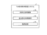
- FIG. 1 is a schematic block diagram of a TiAl alloy powder production system according to the present embodiment.
- FIG. 2 is a schematic view of the hydrotreating apparatus according to the present embodiment.
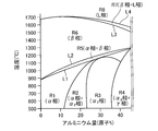
- FIG. 3A is a schematic view showing an example of a phase diagram of a TiAl alloy.
- FIG. 3B is a schematic view showing an example of the phase diagram of the TiAl alloy.
- FIG. 4 is a schematic view of the dehydrogenation treatment apparatus according to the present embodiment.
- FIG. 5 is a flow chart for explaining a method of producing a TiAl alloy powder.
- FIG. 6 is a table showing the results of the compressive breaking strength of the example and the comparative example.
- FIG. 1 is a schematic block diagram of a TiAl alloy powder production system according to the present embodiment.
- the TiAl alloy powder production system 1 according to the present embodiment is a system for producing a TiAl alloy powder using a TiAl alloy body. As shown in FIG. 1, the TiAl alloy powder production system 1 has a hydrotreating unit 10, a dehydrogenation treating unit 12, and a pulverizing unit 14.
- the hydrogenation treatment apparatus 10 is an apparatus for subjecting the TiAl alloy body A1 to a hydrogenation treatment.
- the TiAl alloy body A1 is a lump (ingot) of a TiAl alloy.
- the TiAl alloy body A1 is an alloy body having a TiAl alloy (TiAl based intermetallic compound) as a main component.
- the TiAl alloy in the present embodiment is an alloy (TiAl, Ti 3 Al, Al 3 Ti, etc.) in which Ti (titanium) and Al (aluminum) are combined, and the mixed material may be in solid solution.
- the mixed substance here is a substance such as a metal other than Ti and Al, for example, Nb (niobium), Cr (chromium), V (vanadium), Mn (manganese), Mo (molybdenum), W (tungsten) And at least one of Ta (tantalum), Si (silicon) and C (carbon).
- the TiAl alloy body A1 contains 19.8 wt% to 79.992 wt% of Ti, 19.8 wt% to 79.992 wt% of Al, and 0 wt% of the mixed material. % Or more and 29.997% by weight or less.
- the TiAl alloy body A1 preferably contains 30% by weight or more and 55% by weight or less of Al. By including Al in this range, the ⁇ phase described later can be appropriately generated.
- the component ratio of the TiAl alloy body A1 is not limited to this but is arbitrary, and may contain unavoidable impurities.
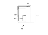
- FIG. 2 is a schematic view of the hydrotreating apparatus according to the present embodiment.
- the hydrotreating apparatus 10 includes a hydrotreating chamber 20, a heating unit 22, and a hydrogen supply unit 24.
- the hydrogenation treatment chamber 20 is a container or a chamber for performing a hydrogenation treatment on the TiAl alloy body A1, and can be isolated from the outside.
- the heating unit 22 is an apparatus for heating the inside of the hydrogenation processing chamber 20 to a predetermined temperature.
- the hydrogen supply unit 24 is a device that discharges the gas (such as air) in the hydrogenation process chamber 20 and supplies hydrogen into the hydrogenation process chamber 20.
- the TiAl alloy body A ⁇ b> 1 is accommodated in the hydrogenation treatment chamber 20. Then, air is discharged from the hydrogenation processing chamber 20 by the hydrogen supply unit 24, and hydrogen is supplied to the hydrogenation processing chamber 20.
- the hydrogen supply unit 24 places the inside of the hydrogenation processing chamber 20 under a hydrogen atmosphere.
- the hydrogen supply unit 24 supplies hydrogen so that the partial pressure of hydrogen in the hydrotreating chamber 20 becomes equal to the atmospheric pressure.
- the hydrogen supply unit 24 preferably supplies hydrogen so that the hydrogen partial pressure in the hydrogenation processing chamber 20 is equal to or higher than atmospheric pressure, and supplies hydrogen so that the hydrogen partial pressure is higher than atmospheric pressure. It is also good.
- the hydrogen supply unit 24 preferably has a hydrogen partial pressure of 1 bar or more and 10 bar or less.
- the hydrogen partial pressure in the hydrogenation treatment chamber 20 is arbitrary.
- the heating unit 22 heats the inside of the hydrogenation processing chamber 20 to a predetermined set temperature, and maintains the set temperature for a predetermined set time.
- the hydrogenation processing apparatus 10 performs a hydrogenation process on the TiAl alloy body A1 under an environment of a set temperature to generate a hydrogen-solidified TiAl alloy body A2 in which hydrogen is solid-solved in the TiAl alloy body A1.
- the set temperature is a temperature equal to or higher than the ⁇ phase transformation start temperature T1, and is a temperature lower than the melting point temperature T2.
- the ⁇ phase transformation start temperature T1 is a temperature at which phase transformation to the ⁇ phase (change of the phase to the ⁇ phase) starts in the TiAl alloy body A1.
- the melting point temperature T2 is a melting point of the TiAl alloy body A1, and is a temperature higher than the ⁇ phase transformation start temperature T1. Moreover, it is preferable that preset temperature is more than (beta) phase transformation completion temperature T3.
- the ⁇ phase transformation completion temperature T3 is a temperature at which the TiAl alloy body A1 completely transforms to the ⁇ phase, which is higher than the ⁇ phase transformation start temperature T1 and lower than the melting point temperature T2.
- the set temperature may be a temperature equal to or higher than the ⁇ phase transformation start temperature T1, and may not be a temperature lower than the melting point temperature T2.
- FIG. 3A is a schematic view showing an example of a phase diagram of a TiAl alloy.
- FIG. 3A is an example of the phase diagram of the TiAl alloy body A1.
- the horizontal axis is the concentration of Al, that is, the content (atomic%), and the vertical axis is the temperature of the TiAl alloy body A1.
- the region R1 in FIG. 3A is a region in which the TiAl alloy body A1 constitutes an ⁇ phase (a close-packed cubic crystal of Ti alone).
- the region R2 is a region corresponding to the position where the content of Al is increased with respect to the region R1.
- the TiAl alloy body A1 constitutes an ⁇ phase and an ⁇ 2 phase (close-packed cubic of Ti 3 Al).
- the region R3 is a region corresponding to the position where the content of Al is increased with respect to the region R2.
- the TiAl alloy body A1 constitutes an ⁇ 2 phase in the region R3.
- the region R4 is a region corresponding to the position where the content of Al is increased with respect to the region R3.
- the TiAl alloy body A1 constitutes the ⁇ 2 phase and the ⁇ phase (face-centered cubic of TiAl) in the region R4.
- the region R5 is a region corresponding to a position where the temperature of the TiAl alloy body A1 is increased relative to the regions R1 to R4.
- the TiAl alloy body A1 constitutes an ⁇ phase and a ⁇ phase (body-centered cubic crystals of Ti).
- the region R6 is a region corresponding to a position where the temperature of the TiAl alloy body A1 is increased relative to the region R5.
- the TiAl alloy body A1 constitutes a ⁇ phase in the region R6.
- the region R7 is a region corresponding to a position where the temperature of the TiAl alloy body A1 is increased relative to the region R6.
- TiAl alloy object A1 constitutes beta phase and L phase (liquid phase) in field R7.
- the region R8 is a region corresponding to a position where the temperature of the TiAl alloy body A1 is increased relative to the region R7.
- the TiAl alloy body A1 constitutes an L phase in the region R8.
- mixed substances are in solid solution in each phase.
- the boundary on the side where the temperature of the region R5 is low that is, the boundary between the regions R1 to R4 and the region R5 is taken as a line L1.
- the line L1 can be said to indicate a boundary at which the phase transformation to the ⁇ phase starts when the temperature is higher than that. That is, the line L1 indicates the ⁇ phase transformation start temperature T1 for each Al concentration.
- the boundary on the side where the temperature of the region R5 is high that is, the boundary between the region R5 and the region R6 is taken as a line L2.
- the line L2 shows the boundary where the ⁇ phase disappears from the TiAl alloy body A1 and the phase is completely transformed to the ⁇ phase (only the ⁇ phase is reached) when the temperature is higher than that. That is, the line L2 indicates the ⁇ phase transformation completion temperature T3 for each Al concentration.
- the boundary on the side where the temperature of the region R6 is high is taken as a line L3.
- the line L3 indicates a boundary at which the phase transformation to the L phase starts when the temperature is higher than that. That is, the line L3 indicates the temperature at which the phase transformation to the L phase for each Al concentration starts.
- the set temperature may be a temperature at which the phase transformation to the L phase starts, that is, a temperature at which the ⁇ phase and the L phase start coexistence, or more.
- the temperature may be lower than the melting point temperature T2.
- the boundary on the side where the temperature of the region R7 is high that is, the boundary between the region R7 and the region R8, is taken as a line L4.
- the line L4 shows a boundary where the ⁇ phase disappears from the TiAl alloy body A1 and the phase is completely transformed to the L phase (only the L phase is reached) when the temperature is higher than that. That is, the line L4 indicates the melting point temperature T2 for each Al concentration.
- FIG. 3A shows an example of the phase diagram of TiAl alloy, and the phase diagram of TiAl alloy changes according to the kind and content ratio of a mixed substance.
- FIG. 3B is a schematic view showing an example of the phase diagram of the TiAl alloy.
- FIG. 3B is an example of a phase diagram of a TiAl alloy containing V (vanadium) as a mixed material.
- the horizontal axis is the concentration of V (atomic%)
- the vertical axis is the temperature of the TiAl alloy body A1.
- the TiAl alloy body A1 containing V includes a region R9 containing an ⁇ phase and a ⁇ phase, and a region R10 containing a ⁇ phase and a ⁇ phase.
- the temperature at which phase transformation occurs and the Al content change according to the type and content ratio of the mixed material. That is, the ⁇ -phase transformation start temperature T1, the ⁇ -phase transformation completion temperature T3 and the melting point temperature T2 change depending on the type and content ratio of the mixed substance, in addition to the Al concentration.
- the ⁇ phase transformation start temperature T1 is a temperature at which the phase transformation of the TiAl alloy body A1 to the ⁇ phase starts
- the ⁇ phase transformation completion temperature T3 Is the temperature at which the phase transformation of the TiAl alloy body A1 to the ⁇ phase ends (the phase transforms completely to the ⁇ phase)
- the melting point temperature T2 is the melting point of the TiAl alloy body A1.
- the TiAl alloy body A1 Since the TiAl alloy body A1 forms an intermetallic compound, it does not easily react chemically with hydrogen and hardly forms a hydride. On the other hand, the TiAl alloy body A1 starts the formation of the ⁇ phase when it reaches the ⁇ phase transformation start temperature T1 or more. Since the ⁇ phase has a wide interatomic space and many hydrogen trap sites, it easily dissolves hydrogen. Therefore, the TiAl alloy body A1 can increase the amount of solid solution of hydrogen when phase-transformed to the ⁇ phase. Therefore, the hydrotreating apparatus 10 performs the hydrotreating on the TiAl alloy body A1 under an environment of a set temperature, that is, the ⁇ phase transformation start temperature T1 or more.
- the hydrotreating apparatus 10 generates the ⁇ phase in the TiAl alloy body A1 by setting the temperature to the ⁇ phase transformation start temperature T1 or more. Then, in the hydrogen treatment apparatus 10, hydrogen is dissolved in the ⁇ phase of the TiAl alloy body A1 in a hydrogen atmosphere, that is, hydrogen is taken into the inside of the TiAl alloy body A1 to form a hydrogen solid solution TiAl alloy body A2. Do.
- the hydrogen-solidified TiAl alloy body A2 has lower strength than the TiAl alloy body A1 due to the solid solution of hydrogen.
- the hydrogen-solidified TiAl alloy body A2 has the same components as the TiAl alloy body A1 except for hydrogen.
- the hydrogen-dissolved TiAl alloy body A2 is naturally cooled or forcibly cooled to normal temperature.
- the hydrogen-solidified TiAl alloy body A2 is cooled, the ⁇ phase undergoes phase transformation to an ⁇ phase etc., but the cause of embrittlement (strength reduction) due to the release, rearrangement, etc. of solid solution hydrogen accompanying phase transformation It becomes.
- preset temperature is 1100 degreeC or more and 1600 degrees C or less. Within this temperature range, the ⁇ phase is appropriately generated in the TiAl alloy body A1, and the TiAl alloy body A1 is not melted. Moreover, as for preset temperature, it is more preferable that they are 1300 degreeC or more and 1600 degrees C or less. Within this temperature range, the TiAl alloy body A1 is not melted while completely transforming the TiAl alloy body A1 into the ⁇ phase. Further, the set time for carrying out the hydrogenation treatment, that is, the time for keeping the TiAl alloy body A1 in the hydrogen atmosphere at the set temperature is optional, but is preferably 0.1 hours or more and 24 hours or less.
- the dehydrogenation processing apparatus 12 dehydrogenates the hydrogen-solidified TiAl alloy body A2 to generate a dehydrogenated TiAl alloy body A3.
- the dehydrogenated TiAl alloy body A3 is obtained by removing hydrogen from the hydrogen-solidified TiAl alloy body A2, and is an alloy body having the same components as the TiAl alloy body A1. However, since the dehydrogenated TiAl alloy body A3 has undergone the hydrogenation treatment, the strength remains lower than that of the TiAl alloy body A1.
- FIG. 4 is a schematic view of the dehydrogenation treatment apparatus according to the present embodiment.
- the dehydrogenation treatment apparatus 12 has a dehydrogenation treatment chamber 30, a heating unit 32, and an exhaust unit 34.
- the dehydrogenation processing chamber 30 is a container or a chamber for dehydrogenating the hydrogen-solidified TiAl alloy body A2, and can be isolated from the outside.
- the heating unit 32 is an apparatus for heating the dehydrogenation processing chamber 30 to a predetermined temperature.
- the exhaust unit 34 is a device that exhausts the gas (such as air) in the dehydrogenation processing chamber 30 to make it vacuum.
- the dehydrogenation processing unit 12 sets the dehydrogenation processing chamber 30 containing the hydrogen-dissolved TiAl alloy body A2 in a vacuum state under a temperature environment of, for example, 400 ° C. or more and 700 ° C. or less for 0.1 hour. Hold for more than 24 hours.
- the dehydrogenation treatment apparatus 12 dehydrogenates the hydrogen-solidified TiAl alloy body A2 to release the hydrogen that has been solid-solved in the hydrogen-solidified TiAl alloy body A2. Thereby, a dehydrogenated TiAl alloy body A3 is generated.
- the hydrotreating apparatus 10 performs a hydrotreating process on the TiAl alloy body A1 to form a hydrogen-solidified TiAl alloy body A2, and the dehydrogenation processor 12 dehydrates the hydrogen-solidified TiAl alloy body A2.
- a dehydrogenation treatment is performed to form a dehydrogenated TiAl alloy body A3. That is, the hydrotreating apparatus 10 and the dehydrogenation processing apparatus 12 perform hydrodehydrogenation on the TiAl alloy body A1.
- the grinding device 14 shown in FIG. 1 is, for example, a mill, but may be any grinding device as long as it can grind the hydrogen-solidified TiAl alloy body A2 or the dehydrogenated TiAl alloy body A3.
- the pulverizing apparatus 14 pulverizes the dehydrogenated TiAl alloy body A3 in a solid state to produce a TiAl alloy powder A4.
- the strength of the dehydrogenated TiAl alloy body A3 is reduced by the hydrogenation treatment. Therefore, the pulverizing apparatus 14 can easily pulverize the dehydrogenated TiAl alloy body A3, and a powder with a small particle size can be easily obtained.
- the grinding device 14 may manufacture the TiAl alloy powder A4 'by grinding the hydrogen-solidified TiAl alloy body A2 before the dehydrogenation treatment in a solid state.
- the hydrogen-solidified TiAl alloy body A2 is a TiAl alloy body that has been subjected to a hydrogenation treatment but has not been subjected to a dehydrogenation treatment.
- the TiAl alloy powder A4 ' is a powder of a TiAl alloy body which has not been subjected to dehydrogenation treatment. Since the strength of the hydrogen-solidified TiAl alloy body A2 is also lowered by the hydrogenation treatment, the pulverizing apparatus 14 can easily grind the hydrogen-solidified TiAl alloy body A2.
- the TiAl alloy powder production system 1 dehydrogenates the TiAl alloy powder A 4 ′ by the dehydrogenation treatment device 12 to produce the TiAl alloy powder A 4.
- the component of the TiAl alloy powder A4 is the same as that of the TiAl alloy body A1. Moreover, since TiAl alloy powder A4 is manufactured by grinding, each particle
- FIG. 5 is a flow chart for explaining a method of producing a TiAl alloy powder.
- the TiAl alloy powder production system 1 performs a hydrogenation treatment on the TiAl alloy body A1 at a set temperature by the hydrogenation treatment apparatus 10 (step S10; hydrogenation treatment step) to obtain a hydrogen-dissolved TiAl alloy.
- step S10 hydrogenation treatment step
- the set temperature is equal to or higher than the ⁇ phase transformation start temperature T1. Therefore, the hydrotreating apparatus 10 can appropriately generate the hydrogen-solidified TiAl alloy body A2 in which hydrogen is solid-solved by increasing the amount of hydrogen solid solution in the TiAl alloy body A1.
- the TiAl alloy powder production system 1 dehydrogenates the hydrogenated TiAl alloy body, that is, the hydrogen-solidified TiAl alloy body A2 by the dehydrogenation treatment apparatus 12 ( Step S12: Dehydrogenation Step)
- a dehydrogenated TiAl alloy body A3 is formed.
- the dehydrogenation processing apparatus 12 releases the hydrogen which has been dissolved in the solid solution in the hydrogen-solidified TiAl alloy body A2 in a vacuum environment of a predetermined temperature under a vacuum environment of a predetermined temperature.
- a dehydrogenated TiAl alloy body A3 is produced.
- the TiAl alloy powder production system 1 grinds the TiAl alloy body after the dehydrogenation treatment is performed by the pulverizing device 14, that is, the dehydrogenated TiAl alloy body A3, and converts the TiAl alloy powder A4. Are generated (step S14). Thereby, the manufacturing flow of TiAl alloy powder A4 is complete
- the TiAl alloy body after the hydrogenation treatment may be pulverized before the dehydrogenation treatment, and the pulverized TiAl alloy body may be dehydrogenated.
- the hydrogen-solidified TiAl alloy body A2 is pulverized by the pulverizing apparatus 14 to form the TiAl alloy powder A4 ′.
- the TiAl alloy powder production system 1 dehydrogenates the TiAl alloy powder A4 'by the dehydrogenation treatment apparatus 12 to produce the TiAl alloy powder A4.
- the strength of the TiAl alloy body is reduced by the hydrogenation treatment. Therefore, as described above, the pulverization treatment may be performed after the hydrogenation treatment, and may be performed before or after the dehydrogenation treatment.
- the hydrodehydrogenation method of the TiAl alloy body according to the present embodiment has a hydrotreating step and a dehydrogenating step.
- the TiAl alloy body A1 is hydrotreated in an environment of a set temperature.
- the set temperature is equal to or higher than the temperature ( ⁇ phase transformation start temperature T1) at which the phase transformation of the TiAl alloy body A1 to the ⁇ phase starts.
- the dehydrogenation step dehydrogenates the hydrotreated TiAl alloy body A1 (hydrogen-solidified TiAl alloy body A2).
- the ⁇ phase is generated in the TiAl alloy body A1 by heating the TiAl alloy body A1 to the ⁇ phase transformation start temperature T1 or more, and the hydrogen solid solution in the TiAl alloy body A1 The amount is increasing.
- This hydrodehydrogenation method appropriately reduces the strength of the TiAl alloy body A1 by causing hydrogen to be dissolved in the TiAl alloy body A1 in this manner.
- this hydrodehydrogenation method can remove the hydrogen which carried out solid solution to TiAl alloy object A1, maintaining a low intensity state by performing a dehydrogenation treatment step.
- the strength of the TiAl alloy body A1 can be appropriately reduced, so that the TiAl alloy powder A4 with a small particle size can be easily manufactured.
- the hydrogenation treatment and the dehydrogenation treatment can be performed, for example, at low cost as compared to the gas atomization method. Therefore, using this hydrodehydrogenation method, a powder of TiAl alloy can be suitably produced.
- the set temperature is preferably a temperature ( ⁇ phase transformation completion temperature T3) at which the TiAl alloy body A1 is completely transformed to the ⁇ phase.
- ⁇ phase transformation completion temperature T3 a temperature at which the TiAl alloy body A1 is completely transformed to the ⁇ phase.
- the set temperature is preferably lower than the melting point (melting point temperature T2) of the TiAl alloy body A1.
- This hydrodehydrogenation method suppresses the TiAl alloy body A1 from becoming the high temperature state of only the L phase in a hydrogen atmosphere by setting the temperature to a temperature above the ⁇ phase transformation start temperature T1 and lower than the melting point temperature T2. As a result, the hydrotreating can be performed more safely.
- preset temperature is 1100 degreeC or more and 1600 degrees C or less.
- this hydrodehydrogenation method by setting the set temperature within this temperature range, the ⁇ phase is appropriately generated in the TiAl alloy body A1, and the TiAl alloy body A1 is not melted. Therefore, this hydrodehydrogenation method can more suitably produce a TiAl alloy powder.
- the hydrotreating step it is preferable to carry out the hydrotreating in an environment in which the partial pressure of hydrogen is equal to or higher than the atmospheric pressure.
- the hydrodehydrogenation method can decrease the strength of the TiAl alloy body A1 more appropriately by increasing the amount of solid solution of hydrogen in the TiAl alloy body A1. Therefore, using this hydrodehydrogenation method, powders of TiAl alloy can be more properly produced.
- the manufacturing method of TiAl alloy powder which concerns on this embodiment grind
- TiAl alloy powder A4 having a small particle diameter can be easily produced, and at low cost. Production of Therefore, the powder of TiAl alloy can be more appropriately manufactured using this manufacturing method.
- the manufacturing method of the TiAl alloy powder which concerns on this embodiment grind
- the body (TiAl alloy powder A4 ′) may be dehydrogenated to produce a TiAl alloy powder A4.
- TiAl alloy powder A4 having a small particle diameter can be easily produced, and at low cost. Production of Therefore, the powder of TiAl alloy can be more appropriately manufactured using this manufacturing method.
- Example 2 Next, an example of the present embodiment will be described.
- a TiAl alloy body containing Nb as a mixed substance was subjected to a hydrogenation treatment for 5 hours at a set temperature of 1400 ° C., that is, a ⁇ phase transformation start temperature T1 or more.
- the hydrogenated TiAl alloy body was subjected to dehydrogenation treatment at 800 ° C. for 3 hours. Thereafter, the compressive fracture strength of the TiAl alloy body after the dehydrogenation treatment was measured. Further, the hydrogen content of the TiAl alloy body before and after the hydrogenation treatment and after the hydrogenation treatment was measured using an inert gas melting method.
- Comparative Example 1 the compressive fracture strength of the TiAl alloy body of the same component was measured without performing the hydrogenation treatment. Then, as Comparative Example 2, the same component TiAl alloy body is subjected to a hydrogenation treatment for 5 hours at 700 ° C., that is, a temperature lower than the ⁇ phase transformation start temperature T 1, and then dehydrogenation treatment for 3 hours at 800 ° C. Did. In Comparative Example 2, the compressive breaking strength of the TiAl alloy body after the dehydrogenation treatment was measured.
- the TiAl alloy body before hydrogenation treatment contains 8 ppm of hydrogen
- the TiAl alloy body after hydrogenation treatment contains 110 ppm of hydrogen content
- the TiAl alloy body after dehydrogenation treatment The hydrogen content was 8 ppm. That is, it is understood that hydrogen is sufficiently dissolved in the TiAl alloy when hydrogen treatment is performed as in this embodiment, and hydrogen is sufficiently removed by dehydrogenation treatment.
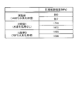
- FIG. 6 is a table showing the results of the compressive breaking strength of the example and the comparative example.
- the compressive fracture strengths of the two samples of the TiAl alloy body after the dehydrogenation treatment in the example were 890 MPa and 967 MPa, respectively.
- the compressive breaking strengths of the two samples were 1710 MPa and 1672 MPa, respectively.
- the compression breaking strength of two samples was 1488 MPa and 1506 MPa, respectively.
- the compressive fracture strength is reduced even when the dehydrogenation treatment is performed thereafter. According to this example, since the compressive strength is reduced as described above, it is understood that the friability of the TiAl alloy powder A4 is improved, and the TiAl alloy powder A4 having a small particle diameter can be easily manufactured.
Landscapes
- Chemical & Material Sciences (AREA)
- Engineering & Computer Science (AREA)
- Materials Engineering (AREA)
- Mechanical Engineering (AREA)
- Metallurgy (AREA)
- Organic Chemistry (AREA)
- Physics & Mathematics (AREA)
- Thermal Sciences (AREA)
- Crystallography & Structural Chemistry (AREA)
- Manufacture Of Metal Powder And Suspensions Thereof (AREA)
Abstract
TiAl合金の粉末を適切に製造する。TiAl合金体の水素化脱水素化方法は、TiAl合金体を、β相への相変態が開始する温度以上である設定温度の環境下で水素化処理する水素化処理ステップと、前記水素化処理を行ったTiAl合金体を、脱水素化処理する脱水素化処理ステップと、を有する。
Description
本発明は、TiAl合金体の水素化脱水素化方法及びTiAl合金粉末の製造方法に関する。
TiAl合金は、Ti(チタン)とAl(アルミニウム)とが結合して構成される合金(金属間化合物)であり、軽量、かつ高温での強度が高いため、エンジンや航空宇宙機器の高温用構造材などへ適用されている。TiAl合金は、展延性が低いなどの理由により、鍛造や鋳造などではなく焼結によって成形されることがある。この際、TiAl合金の粉末を必要な形状に成形して、その成形体を焼結することで、TiAl合金の製品を製造する。
TiAl合金の粉末は、一般的に、TiAl合金体(TiAl合金のインゴット)をガスアトマイズ法などで微粉化することにより、製造される。また、特許文献1に示すように、チタンでは、水素化脱水素化(HDH:Hydride-DeHydride)法を用いて、粉末を製造する場合がある。チタンを用いた水素化脱水素化法は、チタンを水素化処理することで脆性的な水素化物(水素化チタン)を形成する。これによりチタンの強度を低下させて、破砕性を向上させている。そして、この強度が低下したチタンを粉砕して、チタン粉末を製造する。
しかし、ガスアトマイズ法では、粒径が小さい粉末を安定して得ることが難しく、かつ、高コストとなる傾向がある。一方、水素化脱水素化法は、低コストであることに加え、粒径が小さい粉末を安定して得ることができる。しかし、TiAl合金は、金属間化合物を形成しているため、水素化物を形成しにくい。従って、チタンと同様な条件で水素化脱水素化処理を行っても、TiAl合金体の強度を低下させることが困難であり、TiAl合金の粉末を適切に製造することはできない。
本発明は、上述した課題を解決するものであり、TiAl合金の粉末を適切に製造するTiAl合金体の水素化脱水素化方法及びTiAl合金粉末の製造方法を提供することを目的とする。
上述した課題を解決し、目的を達成するために、本開示に係るTiAl合金体の水素化脱水素化方法は、TiAl合金体を、β相への相変態が開始する温度以上である設定温度の環境下で水素化処理する水素化処理ステップと、前記水素化処理を行ったTiAl合金体を、脱水素化処理する脱水素化処理ステップと、を有する。このTiAl合金体の水素化脱水素化方法は、β相への相変態が開始する温度以上とすることで、TiAl合金体内にβ相を生成させて、TiAl合金体内の水素の固溶量を増加させている。この水素化脱水素化方法は、このようにTiAl合金体に水素を固溶させることで、TiAl合金体の強度を適切に低下させて、TiAl合金の粉末を適切に製造することを可能としている。
前記TiAl合金体の水素化脱水素化方法において、前記設定温度は、前記TiAl合金体がβ相へ完全に相変態する温度以上であることが好ましい。これにより、この水素化脱水素化方法は、TiAl合金体内の水素固溶量をより増加させて、TiAl合金体の強度をより適切に低下させることができる。従って、この水素化脱水素化方法を用いると、TiAl合金の粉末をより適切に製造することができる。
前記TiAl合金体の水素化脱水素化方法において、前記設定温度は、前記TiAl合金体の融点より低い温度であることが好ましい。この水素化脱水素化方法は、TiAl合金体を融点より低い温度とすることで、水素雰囲気下でL相のみの高温状態となることを抑制して、水素化処理をより安全に行うことが可能となる。
前記TiAl合金体の水素化脱水素化方法において、設定温度は、1100℃以上1600℃未満であることが好ましい。この水素化脱水素化方法は、設定温度をこの温度範囲内とすることで、TiAl合金体内にβ相を適切に生成させ、かつ、TiAl合金体が溶融しない状態とする。従って、この水素化脱水素化方法は、TiAl合金の粉末をより適切に製造することができる。
前記TiAl合金体の水素化脱水素化方法において、前記水素化処理ステップは、水素の分圧が大気圧以上となる環境下で水素化処理を行うことが好ましい。この水素化脱水素化方法は、これにより、TiAl合金体内の水素固溶量を増加させて、TiAl合金体の強度をより適切に低下させることができる。従って、この水素化脱水素化方法を用いると、TiAl合金の粉末をより適切に製造することができる。
上述した課題を解決し、目的を達成するために、本開示に係るTiAl合金粉末の製造方法は、前記TiAl合金体の水素化脱水素化方法で前記脱水素化処理を行ったTiAl合金体を粉砕して、TiAl合金粉末を製造する。このTiAl合金粉末の製造方法は、水素化脱水素化方法によってTiAl合金体の強度を低下させているため、TiAl合金の粉末をより適切に製造することができる。
上述した課題を解決し、目的を達成するために、本開示に係るTiAl合金粉末の製造方法は、前記TiAl合金体の水素化脱水素化方法で前記水素化処理を行ったTiAl合金体を粉砕し、粉砕したTiAl合金体を脱水素化処理して、TiAl合金粉末を製造する。このTiAl合金粉末の製造方法は、水素化処理によってTiAl合金体の強度を低下させているため、TiAl合金の粉末をより適切に製造することができる。
本発明によれば、TiAl合金の粉末を適切に製造することができる。
以下に添付図面を参照して、本発明の好適な実施形態を詳細に説明する。なお、この実施形態により本発明が限定されるものではなく、また、実施形態が複数ある場合には、各実施形態を組み合わせて構成するものも含むものである。
(実施形態)
図1は、本実施形態に係るTiAl合金粉末製造システムの模式的なブロック図である。本実施形態に係るTiAl合金粉末製造システム1は、TiAl合金体を用いてTiAl合金粉末を製造するシステムである。図1に示すように、TiAl合金粉末製造システム1は、水素化処理装置10と、脱水素化処理装置12と、粉砕装置14と、を有する。
図1は、本実施形態に係るTiAl合金粉末製造システムの模式的なブロック図である。本実施形態に係るTiAl合金粉末製造システム1は、TiAl合金体を用いてTiAl合金粉末を製造するシステムである。図1に示すように、TiAl合金粉末製造システム1は、水素化処理装置10と、脱水素化処理装置12と、粉砕装置14と、を有する。
水素化処理装置10は、TiAl合金体A1に水素化処理を施す装置である。TiAl合金体A1は、TiAl合金の塊(インゴット)である。TiAl合金体A1は、TiAl合金(TiAl系金属間化合物)を主成分とする合金体である。本実施形態におけるTiAl合金とは、Ti(チタン)とAl(アルミニウム)とが結合した合金(TiAl、Ti3Al、Al3Ti等)であり、さらに混合物質が固溶していてもよい。ここでの混合物質は、Ti及びAl以外の金属などの物質であり、例えば、Nb(ニオブ)、Cr(クロム)、V(バナジウム)、Mn(マンガン)、Mo(モリブデン)、W(タングステン)、Ta(タンタル)、Si(シリコン)及びC(カーボン)のうち少なくともいずれか一種を含有するものである。本実施形態において、TiAl合金体A1は、Tiが19.8重量%以上79.992重量%以下であり、Alが19.8重量%以上79.992重量%以下であり、混合物質が0重量%以上29.997重量%以下である。ただし、TiAl合金体A1は、Alを30重量%以上55重量%以下含むことが好ましい。この範囲でAlを含むことにより、後述するβ相を適切に生成することができる。ただし、TiAl合金体A1の成分比は、これに限られず任意であり、また、不可避的不純物を含んでもよい。
図2は、本実施形態に係る水素化処理装置の模式図である。図2に示すように、水素化処理装置10は、水素化処理室20と、加熱部22と、水素供給部24と、を有する。水素化処理室20は、TiAl合金体A1に水素化処理を行うための容器又は部屋であり、外部から隔離可能となっている。加熱部22は、水素化処理室20内を所定の温度に加熱する装置である。水素供給部24は、水素化処理室20内の気体(空気等)を排出し、水素化処理室20内に水素を供給する装置である。
水素化処理装置10を用いて水素化処理を行う場合、TiAl合金体A1を水素化処理室20の内部に収納する。そして、水素供給部24により、水素化処理室20内から空気を排出して、水素化処理室20内に水素を供給する。これにより、水素供給部24は、水素化処理室20内を水素雰囲気下にする。水素供給部24は、水素化処理室20内の水素分圧が大気圧と同じになるように、水素を供給する。なお、水素供給部24は、水素化処理室20内の水素分圧が大気圧以上となるように水素を供給することが好ましく、水素分圧が大気圧より高くなるように水素を供給してもよい。例えば、水素供給部24は、水素分圧を1bar以上10bar以下とすることが好ましい。ただし、水素化処理室20内の水素分圧は任意である。
加熱部22は、水素化処理室20内を所定の設定温度まで加熱し、所定の設定時間の間、設定温度のまま維持する。これにより、水素化処理装置10は、TiAl合金体A1を、設定温度の環境下で水素化処理して、TiAl合金体A1に水素が固溶した水素固溶TiAl合金体A2を生成する。この設定温度は、β相変態開始温度T1以上の温度であり、融点温度T2より低い温度である。β相変態開始温度T1とは、TiAl合金体A1において、β相への相変態(β相への相の変化)が開始する温度である。融点温度T2は、TiAl合金体A1の融点であり、β相変態開始温度T1より高い温度である。また、設定温度は、β相変態完了温度T3以上であることが好ましい。β相変態完了温度T3は、TiAl合金体A1がβ相に完全に相変態する温度であり、β相変態開始温度T1より高く融点温度T2より低い。ただし、設定温度は、β相変態開始温度T1以上の温度であればよく、融点温度T2より低い温度でなくてもよい。
以下、状態図を用いて、β相変態開始温度T1、β相変態完了温度T3、及び融点温度T2を説明する。図3Aは、TiAl合金の状態図の一例を示す模式図である。図3Aは、TiAl合金体A1の状態図の一例であり、横軸がAlの濃度、すなわち含有量(原子%)であり、縦軸がTiAl合金体A1の温度である。
図3Aに示すように、TiAl合金体A1は、Alの含有量とTiAl合金体A1の温度とによって、金属相が変化する。図3Aの領域R1は、TiAl合金体A1が、α相(Ti単体の最密立方晶)を構成する領域である。領域R2は、領域R1に対しAlの含有量を増加させた位置に対応する領域である。TiAl合金体A1は、領域R2では、α相とα2相(Ti3Alの最密立方晶)とを構成する。領域R3は、領域R2に対しAlの含有量を増加させた位置に対応する領域である。TiAl合金体A1は、領域R3では、α2相を構成する。領域R4は、領域R3に対しAlの含有量を増加させた位置に対応する領域である。TiAl合金体A1は、領域R4では、α2相とγ相(TiAlの面心立方晶)とを構成する。
領域R5は、領域R1から領域R4に対しTiAl合金体A1の温度を高くした位置に対応する領域である。TiAl合金体A1は、領域R5では、α相とβ相(Tiの体心立方晶)とを構成する。領域R6は、領域R5に対しTiAl合金体A1の温度を高くした位置に対応する領域である。TiAl合金体A1は、領域R6では、β相を構成する。領域R7は、領域R6に対しTiAl合金体A1の温度を高くした位置に対応する領域である。TiAl合金体A1は、領域R7では、β相とL相(液相)とを構成する。領域R8は、領域R7に対しTiAl合金体A1の温度を高くした位置に対応する領域である。TiAl合金体A1は、領域R8では、L相を構成する。なお、いずれの領域においても、各相には、混合物質が固溶している。
ここで、領域R5の温度が低い側の境界線、すなわち、領域R1から領域R4と、領域R5との境界線を、線L1とする。線L1は、それを超える温度になるとβ相への相変態を開始する境界を示しているということができる。すなわち、線L1は、Al濃度毎のβ相変態開始温度T1を示している。また、領域R5の温度が高い側の境界線、すなわち領域R5と領域R6との境界線を、線L2とする。線L2は、それを超える温度になると、TiAl合金体A1からα相が消滅して、β相へ完全に相変態する(β相のみとなる)境界を示しているということができる。すなわち、線L2は、Al濃度毎のβ相変態完了温度T3を示している。
また、領域R6の温度が高い側の境界線、すなわち領域R6と領域R7との境界線を、線L3とする。線L3は、それを超える温度になるとL相への相変態を開始する境界を示しているということができる。すなわち、線L3は、Al濃度毎のL相への相変態を開始する温度を示している。なお、水素化処理装置10は、設定温度を、このL相への相変態を開始する温度、すなわちβ相とL相とが共存を開始する温度以上としてもよく、さらにこの温度以上であって融点温度T2より低い温度としてもよい。また、領域R7の温度が高い側の境界線、すなわち領域R7と領域R8との境界線を、線L4とする。線L4は、それを超える温度になると、TiAl合金体A1からβ相が消滅して、L相に完全に相変態する(L相のみとなる)境界を示しているということができる。すなわち、線L4は、Al濃度毎の融点温度T2を示している。
線L1、L2、L4に示すように、β相変態開始温度T1、β相変態完了温度T3及び融点温度T2は、Alの含有量によって変化する。また、図3Aは、TiAl合金の状態図の一例を示すものであり、TiAl合金の状態図は、混合物質の種類や含有比に応じて変化する。図3Bは、TiAl合金の状態図の一例を示す模式図である。図3Bは、混合物質としてV(バナジウム)を含むTiAl合金の状態図の一例である。図3Bは、横軸がVの濃度(原子%)であり、縦軸がTiAl合金体A1の温度である。図3BのTiAl合金体A1は、Alが42%(原子%)含まれている。図3Bに示すように、Vが含まれたTiAl合金体A1は、α相とγ相とが含まれる領域R9と、β相とγ相とが含まれる領域R10と、を含む。図3A及び図3Bに示すように、TiAl合金は、相変態が起こる温度及びAl含有量(線L1から線L4の形状に相当)が、混合物質の種類や含有比に応じて変化する。すなわち、β相変態開始温度T1、β相変態完了温度T3及び融点温度T2は、Al濃度に加え、混合物質の種類や含有比によっても変化する。ただし、TiAl合金体A1の成分比がいずれの場合であっても、β相変態開始温度T1は、TiAl合金体A1のβ相への相変態が開始する温度であり、β相変態完了温度T3は、TiAl合金体A1のβ相への相変態が終了する(完全にβ相へ相変態する)温度であり、融点温度T2は、TiAl合金体A1の融点である。
TiAl合金体A1は、金属間化合物を形成しているため、水素と化学反応しにくく、水素化物を形成し難い。一方、TiAl合金体A1は、β相変態開始温度T1以上になると、β相の形成を開始する。β相は、原子間空隙が広く、水素トラップサイトも多いため、水素を固溶し易い。従って、TiAl合金体A1は、β相に相変態すると、水素の固溶量を増加させることができる。そのため、水素化処理装置10は、設定温度、すなわちβ相変態開始温度T1以上の環境下で、TiAl合金体A1に水素化処理を行っている。水素化処理装置10は、β相変態開始温度T1以上とすることで、TiAl合金体A1にβ相を生成させる。そして、水素化処理装置10は、水素雰囲気下でTiAl合金体A1のβ相に水素を固溶させて、すなわちTiAl合金体A1内部に水素を取り込ませて、水素固溶TiAl合金体A2を生成する。水素固溶TiAl合金体A2は、水素を固溶することで、TiAl合金体A1よりも強度が低下する。水素固溶TiAl合金体A2は、水素以外の成分が、TiAl合金体A1と同じである。
水素固溶TiAl合金体A2は、その後、常温まで自然冷却又は強制冷却される。水素固溶TiAl合金体A2は、冷却されることで、β相がα相などに相変態するが、相変態に伴う固溶水素の放出、再配置などにより、脆化(強度低下)の要因となる。
なお、設定温度は、1100℃以上1600℃以下であることが好ましい。この温度範囲であれば、TiAl合金体A1内にβ相を適切に生成させ、かつ、TiAl合金体A1が溶融しない。また、設定温度は、1300℃以上1600℃以下であることがより好ましい。この温度範囲であれば、TiAl合金体A1を完全にβ相に相変態させつつ、TiAl合金体A1が溶融しない。また、水素化処理を行う設定時間、すなわちTiAl合金体A1を設定温度下で水素雰囲気内に保持する時間は、任意であるが、0.1時間以上24時間以下であることが好ましい。
次に、図1に示す脱水素化処理装置12について説明する。脱水素化処理装置12は、水素固溶TiAl合金体A2に脱水素化処理を行い、脱水素TiAl合金体A3を生成する。脱水素TiAl合金体A3は、水素固溶TiAl合金体A2から水素が除去されたものであり、TiAl合金体A1と同じ成分の合金体である。ただし、脱水素TiAl合金体A3は、水素化処理を経ているので、強度はTiAl合金体A1より低いままとなっている。
図4は、本実施形態に係る脱水素化処理装置の模式図である。図4に示すように、脱水素化処理装置12は、脱水素化処理室30と、加熱部32と、排気部34と、を有する。脱水素化処理室30は、水素固溶TiAl合金体A2に脱水素化処理を行うための容器又は部屋であり、外部から隔離可能となっている。加熱部32は、脱水素化処理室30を所定の温度に加熱する装置である。排気部34は、脱水素化処理室30内の気体(空気等)を排出して真空とする装置である。
脱水素化処理装置12は、水素固溶TiAl合金体A2が収納された脱水素化処理室30を、例えば400℃以上700℃以下の温度環境下の真空状態として、その状態を0.1時間以上24時間以下の間保持する。これにより、脱水素化処理装置12は、水素固溶TiAl合金体A2を脱水素化処理して、水素固溶TiAl合金体A2内部に固溶していた水素を放出させる。これにより、脱水素TiAl合金体A3が生成される。
このように、水素化処理装置10は、TiAl合金体A1に水素化処理を行って水素固溶TiAl合金体A2を生成し、脱水素化処理装置12は、水素固溶TiAl合金体A2に脱水素化処理を行って脱水素TiAl合金体A3を生成する。すなわち、水素化処理装置10及び脱水素化処理装置12は、TiAl合金体A1に水素化脱水素化処理を行う。
図1に示す粉砕装置14は、例えばミルなどであるが、水素固溶TiAl合金体A2または脱水素TiAl合金体A3を粉砕可能であれば、任意の粉砕装置であってよい。粉砕装置14は、脱水素TiAl合金体A3を固体のまま粉砕して、TiAl合金粉末A4を製造する。脱水素TiAl合金体A3は、水素化処理によって強度が低下している。従って、粉砕装置14は、脱水素TiAl合金体A3を容易に粉砕することが可能となり、粒径が小さい粉末を容易に得ることができる。なお、粉砕装置14は、脱水素化処理前の水素固溶TiAl合金体A2を固体のまま粉砕して、TiAl合金粉末A4’を製造してもよい。水素固溶TiAl合金体A2は、水素化処理が行われているが、脱水素化処理は行われていないTiAl合金体である。TiAl合金粉末A4’は、脱水素化処理が行われていないTiAl合金体の粉末である。水素固溶TiAl合金体A2も、水素化処理によって強度が低下しているため、粉砕装置14は、水素固溶TiAl合金体A2を容易に粉砕可能である。この場合、TiAl合金粉末製造システム1は、TiAl合金粉末A4’を脱水素化処理装置12によって脱水素化処理して、TiAl合金粉末A4を製造する。なお、TiAl合金粉末A4は、成分がTiAl合金体A1と同じである。また、TiAl合金粉末A4は、粉砕により製造されるので、粒子それぞれが凹凸状となっている。
次に、TiAl合金粉末A4の製造方法をフローチャートに基づき説明する。図5は、TiAl合金粉末の製造方法を説明するフローチャートである。図5に示すように、TiAl合金粉末製造システム1は、水素化処理装置10により、TiAl合金体A1を設定温度で水素化処理して(ステップS10;水素化処理ステップ)、水素固溶TiAl合金体A2を生成する。設定温度は、β相変態開始温度T1以上である。従って、水素化処理装置10は、TiAl合金体A1への水素固溶量を増加させて、水素が固溶した水素固溶TiAl合金体A2を適切に生成できる。
水素化処理を行った後、TiAl合金粉末製造システム1は、脱水素化処理装置12により、水素化処理されたTiAl合金体、すなわち水素固溶TiAl合金体A2を、脱水素化処理して(ステップS12;脱水素化処理ステップ)、脱水素TiAl合金体A3を生成する。具体的には、脱水素化処理装置12は、冷却された水素固溶TiAl合金体A2を所定温度の真空環境下において、水素固溶TiAl合金体A2内部に固溶していた水素を放出させて、脱水素TiAl合金体A3を生成する。
脱水素化処理を行った後、TiAl合金粉末製造システム1は、粉砕装置14により脱水素化処理を行った後のTiAl合金体、すなわち脱水素TiAl合金体A3を粉砕して、TiAl合金粉末A4を生成する(ステップS14)。これにより、TiAl合金粉末A4の製造フローは終了する。
なお、TiAl合金粉末製造システム1は、水素化処理を行った後のTiAl合金体を、脱水素化処理の前に粉砕し、粉砕したTiAl合金体を脱水素化処理してもよい。この場合、TiAl合金粉末製造システム1は、ステップS10で水素固溶TiAl合金体A2を生成した後、粉砕装置14により、水素固溶TiAl合金体A2を粉砕して、TiAl合金粉末A4’を生成する。その後、TiAl合金粉末製造システム1は、脱水素化処理装置12により、TiAl合金粉末A4’を脱水素化処理して、TiAl合金粉末A4を生成する。TiAl合金体は、水素化処理により強度が低下する。従って、以上説明したように、粉砕処理を行うのは、水素化処理を行った後であればよく、脱水素化処理の前でも後でもよい。
以上説明したように、本実施形態に係るTiAl合金体の水素化脱水素化方法は、水素化処理ステップと、脱水素化処理ステップとを有する。水素化処理ステップは、TiAl合金体A1を、設定温度の環境下で水素化処理する。設定温度は、TiAl合金体A1のβ相への相変態が開始する温度(β相変態開始温度T1)以上である。脱水素化処理ステップは、水素化処理を行ったTiAl合金体A1(水素固溶TiAl合金体A2)を、脱水素化処理する。
この水素化脱水素化方法は、TiAl合金体A1をβ相変態開始温度T1以上に加熱することで、TiAl合金体A1内にβ相を生成させて、TiAl合金体A1内への水素固溶量を増加させている。この水素化脱水素化方法は、このようにTiAl合金体A1に水素を固溶させることで、TiAl合金体A1の強度を適切に低下させる。そして、この水素化脱水素化方法は、脱水素化処理ステップを実行することにより、強度が低い状態に維持したまま、TiAl合金体A1に固溶した水素を除去することができる。この水素化脱水素化方法を用いると、TiAl合金体A1の強度を適切に低下させることができるため、粒径が小さいTiAl合金粉末A4を容易に製造することができる。また、水素化処理と脱水素化処理は、例えばガスアトマイズ法に比べて低コストで実行することができる。従って、この水素化脱水素化方法を用いると、TiAl合金の粉末を適切に製造することができる。
また、設定温度は、TiAl合金体A1がβ相へ完全に相変態する温度(β相変態完了温度T3)以上であることが好ましい。この水素化脱水素化方法は、TiAl合金体A1をβ相変態完了温度T3以上に加熱することで、TiAl合金体A1の全ての相をβ相とすることができる。これにより、水素化脱水素化方法は、TiAl合金体A1内の水素固溶量を増加させて、TiAl合金体A1の強度をより適切に低下させることができる。従って、この水素化脱水素化方法を用いると、TiAl合金の粉末をより適切に製造することができる。
また、設定温度は、TiAl合金体A1の融点(融点温度T2)より低い温度であることが好ましい。この水素化脱水素化方法は、TiAl合金体A1をβ相変態開始温度T1以上であって融点温度T2より低い温度とすることで、水素雰囲気下でL相のみの高温状態となることを抑制して、水素化処理をより安全に行うことが可能となる。
また、設定温度は、1100℃以上1600℃以下であることが好ましい。この水素化脱水素化方法は、設定温度をこの温度範囲内とすることで、TiAl合金体A1内にβ相を適切に生成させ、かつ、TiAl合金体A1が溶融しない状態とする。従って、この水素化脱水素化方法は、TiAl合金の粉末をより適切に製造することができる。
また、水素化処理ステップは、水素の分圧が大気圧以上となる環境下で水素化処理を行うことが好ましい。これにより、水素化脱水素化方法は、TiAl合金体A1内の水素固溶量を増加させて、TiAl合金体A1の強度をより適切に低下させることができる。従って、この水素化脱水素化方法を用いると、TiAl合金の粉末をより適切に製造することができる。
また、本実施形態に係るTiAl合金粉末の製造方法は、上記の水素化脱水素化方法で脱水素化処理を行ったTiAl合金体(脱水素TiAl合金体A3)を粉砕して、TiAl合金粉末A4を製造する。このTiAl合金粉末の製造方法は、水素化脱水素化方法によってTiAl合金体A1の強度を低下させているため、粒径が小さいTiAl合金粉末A4を容易に製造することができ、かつ低コストでの製造が可能となる。従って、この製造方法を用いると、TiAl合金の粉末をより適切に製造することができる。
また、本実施形態に係るTiAl合金粉末の製造方法は、上記の水素化脱水素化方法で水素化処理を行ったTiAl合金体(水素固溶TiAl合金体A2)を粉砕し、粉砕したTiAl合金体(TiAl合金粉末A4’)を脱水素化処理して、TiAl合金粉末A4を製造してもよい。このTiAl合金粉末の製造方法は、水素化脱水素化方法によってTiAl合金体A1の強度を低下させているため、粒径が小さいTiAl合金粉末A4を容易に製造することができ、かつ低コストでの製造が可能となる。従って、この製造方法を用いると、TiAl合金の粉末をより適切に製造することができる。
(実施例)
次に、本実施形態の実施例について説明する。本実施例では、Nbを混合物質として含有するTiAl合金体を、設定温度を1400℃、すなわちβ相変態開始温度T1以上として、5時間の水素化処理を行った。そして、水素化処理した後のTiAl合金体を、800℃で3時間の脱水素化処理を行った。その後、脱水素化処理した後のTiAl合金体の圧縮破断強度を測定した。また、水素化処理前、水素化処理後、脱水素化処理後のそれぞれにおけるTiAl合金体の水素含有量を、不活性ガス溶融法を用いて測定した。
次に、本実施形態の実施例について説明する。本実施例では、Nbを混合物質として含有するTiAl合金体を、設定温度を1400℃、すなわちβ相変態開始温度T1以上として、5時間の水素化処理を行った。そして、水素化処理した後のTiAl合金体を、800℃で3時間の脱水素化処理を行った。その後、脱水素化処理した後のTiAl合金体の圧縮破断強度を測定した。また、水素化処理前、水素化処理後、脱水素化処理後のそれぞれにおけるTiAl合金体の水素含有量を、不活性ガス溶融法を用いて測定した。
また、比較例1として、同成分のTiAl合金体について、水素化処理を行わないまま、圧縮破断強度を測定した。そして、比較例2として、同成分のTiAl合金体について、700℃、すなわちβ相変態開始温度T1より低い温度で、5時間の水素化処理を行い、その後800℃で3時間の脱水素化処理を行った。比較例2では、その脱水素化処理後のTiAl合金体の圧縮破断強度を測定した。
実施例において、水素化処理前のTiAl合金体は、含有水素量が8ppmであり、水素化処理後のTiAl合金体は、含有水素量が110ppmであり、脱水素化処理後のTiAl合金体は、含有水素量が8ppmであった。すなわち、本実施例のように水素化処理を行うと、水素が十分にTiAl合金体内に固溶し、脱水素化処理により、水素が十分に除去されることが分かる。
図6は、実施例と比較例との圧縮破断強度の結果を示す表である。図6に示すように、実施例で脱水素化処理を行った後のTiAl合金体は、2つのサンプルの圧縮破断強度が、それぞれ890MPa、967MPaであった。一方、比較例1で水素化処理を行わないTiAl合金体は、2つのサンプルの圧縮破断強度が、それぞれ1710MPa、1672MPaであった。また、比較例2で脱水素化処理を行った後のTiAl合金体は、2つのサンプルの圧縮破断強度が、それぞれ1488MPa、1506MPaであった。このように、β相変態開始温度T1以上で水素化処理を行うと、その後脱水素化処理を行った場合でも、圧縮破断強度が低下することが分かる。本実施例によると、このように圧縮強度が低下するため、TiAl合金粉末A4の破砕性が向上し、粒径が小さいTiAl合金粉末A4を容易に製造することが可能となることが分かる。
以上、本発明の実施形態を説明したが、この実施形態の内容により実施形態が限定されるものではない。また、前述した構成要素には、当業者が容易に想定できるもの、実質的に同一のもの、いわゆる均等の範囲のものが含まれる。さらに、前述した構成要素は適宜組み合わせることが可能である。さらに、前述した実施形態の要旨を逸脱しない範囲で構成要素の種々の省略、置換又は変更を行うことができる。
1 TiAl合金粉末製造システム
10 水素化処理装置
12 脱水素化処理装置
14 粉砕装置
20 水素化処理室
22、32 加熱部
24 水素供給部
30 脱水素化処理室
34 排気部
A1 TiAl合金体
A2 水素固溶TiAl合金体
A3 脱水素TiAl合金体
A4 TiAl合金粉末
T1 β相変態開始温度
T2 融点温度
T3 β相変態完了温度
10 水素化処理装置
12 脱水素化処理装置
14 粉砕装置
20 水素化処理室
22、32 加熱部
24 水素供給部
30 脱水素化処理室
34 排気部
A1 TiAl合金体
A2 水素固溶TiAl合金体
A3 脱水素TiAl合金体
A4 TiAl合金粉末
T1 β相変態開始温度
T2 融点温度
T3 β相変態完了温度
Claims (7)
- TiAl合金体を、β相への相変態が開始する温度以上である設定温度の環境下で水素化処理する水素化処理ステップと、
前記水素化処理を行ったTiAl合金体を、脱水素化処理する脱水素化処理ステップと、
を有するTiAl合金体の水素化脱水素化方法。 - 前記設定温度は、前記TiAl合金体がβ相へ完全に相変態する温度以上である、請求項1に記載のTiAl合金体の水素化脱水素化方法。
- 前記設定温度は、前記TiAl合金体の融点より低い温度である、請求項1又は請求項2に記載のTiAl合金体の水素化脱水素化方法。
- 前記設定温度は、1100℃以上1600℃未満である、請求項1から請求項3のいずれか1項に記載のTiAl合金体の水素化脱水素化方法。
- 前記水素化処理ステップは、水素の分圧が大気圧以上となる環境下で水素化処理を行う、請求項1から請求項4のいずれか1項に記載のTiAl合金体の水素化脱水素化方法。
- 請求項1から請求項5のいずれか1項に記載のTiAl合金体の水素化脱水素化方法で前記脱水素化処理を行ったTiAl合金体を粉砕して、TiAl合金粉末を製造する、TiAl合金粉末の製造方法。
- 請求項1から請求項5のいずれか1項に記載のTiAl合金体の水素化脱水素化方法で前記水素化処理を行ったTiAl合金体を粉砕し、粉砕したTiAl合金体を脱水素化処理して、TiAl合金粉末を製造するTiAl合金粉末の製造方法。
Priority Applications (3)
| Application Number | Priority Date | Filing Date | Title |
|---|---|---|---|
| CA3029174A CA3029174C (en) | 2016-12-07 | 2017-12-06 | Hydrogenation-dehydrogenation method for tial alloy and method for producing tial alloy powder |
| US16/319,643 US11583923B2 (en) | 2016-12-07 | 2017-12-06 | Hydrogenation-dehydrogenation method for TiAl alloy and method for producing TiAl alloy powder |
| EP17879128.1A EP3552740B1 (en) | 2016-12-07 | 2017-12-06 | Method for producing an alloy powder having a tial-based intermetallic compound as a main component |
Applications Claiming Priority (2)
| Application Number | Priority Date | Filing Date | Title |
|---|---|---|---|
| JP2016237870A JP6402163B2 (ja) | 2016-12-07 | 2016-12-07 | TiAl合金体の水素化脱水素化方法及びTiAl合金粉末の製造方法 |
| JP2016-237870 | 2016-12-07 |
Publications (1)
| Publication Number | Publication Date |
|---|---|
| WO2018105664A1 true WO2018105664A1 (ja) | 2018-06-14 |
Family
ID=62491174
Family Applications (1)
| Application Number | Title | Priority Date | Filing Date |
|---|---|---|---|
| PCT/JP2017/043858 WO2018105664A1 (ja) | 2016-12-07 | 2017-12-06 | TiAl合金体の水素化脱水素化方法及びTiAl合金粉末の製造方法 |
Country Status (5)
| Country | Link |
|---|---|
| US (1) | US11583923B2 (ja) |
| EP (1) | EP3552740B1 (ja) |
| JP (1) | JP6402163B2 (ja) |
| CA (1) | CA3029174C (ja) |
| WO (1) | WO2018105664A1 (ja) |
Families Citing this family (13)
| Publication number | Priority date | Publication date | Assignee | Title |
|---|---|---|---|---|
| US10987735B2 (en) * | 2015-12-16 | 2021-04-27 | 6K Inc. | Spheroidal titanium metallic powders with custom microstructures |
| EP4324577A1 (en) | 2015-12-16 | 2024-02-21 | 6K Inc. | Method of producing spheroidal dehydrogenated titanium alloy particles |
| SG11202005142XA (en) * | 2017-12-18 | 2020-07-29 | Hitachi Metals Ltd | Method for producing tial intermetallic compound powder, and tial intermetallic compound powder |
| WO2019205830A1 (zh) * | 2018-04-25 | 2019-10-31 | 中南大学 | 一种利用金属吸氢膨胀促进金属坯体致密化的方法 |
| AU2020264446A1 (en) | 2019-04-30 | 2021-11-18 | 6K Inc. | Mechanically alloyed powder feedstock |
| WO2020223374A1 (en) | 2019-04-30 | 2020-11-05 | 6K Inc. | Lithium lanthanum zirconium oxide (llzo) powder |
| EP4061787B1 (en) | 2019-11-18 | 2024-05-01 | 6K Inc. | Unique feedstocks for spherical powders and methods of manufacturing |
| US11590568B2 (en) | 2019-12-19 | 2023-02-28 | 6K Inc. | Process for producing spheroidized powder from feedstock materials |
| EP4173060A1 (en) | 2020-06-25 | 2023-05-03 | 6K Inc. | Microcomposite alloy structure |
| US11963287B2 (en) | 2020-09-24 | 2024-04-16 | 6K Inc. | Systems, devices, and methods for starting plasma |
| AU2021371051A1 (en) | 2020-10-30 | 2023-03-30 | 6K Inc. | Systems and methods for synthesis of spheroidized metal powders |
| CN114309621B (zh) * | 2021-12-28 | 2023-11-10 | 云航时代(重庆)科技有限公司 | 一种含有难熔金属元素的微细TiAl合金球形粉体的制备方法 |
| CN115976386B (zh) * | 2022-12-20 | 2024-05-17 | 承德天大钒业有限责任公司 | 一种低氧铝钼钨钛中间合金及其制备方法 |
Citations (3)
| Publication number | Priority date | Publication date | Assignee | Title |
|---|---|---|---|---|
| JPH05339606A (ja) * | 1992-06-05 | 1993-12-21 | Toho Titanium Co Ltd | チタン系粉末の製造方法およびその装置 |
| JP2009221603A (ja) * | 2008-02-20 | 2009-10-01 | Hitachi Metals Ltd | 球状チタン合金粉末の製造方法 |
| JP2013053333A (ja) * | 2011-09-02 | 2013-03-21 | Toho Titanium Co Ltd | チタン合金の水素化方法 |
Family Cites Families (7)
| Publication number | Priority date | Publication date | Assignee | Title |
|---|---|---|---|---|
| JPH03122205A (ja) | 1989-10-05 | 1991-05-24 | Nippon Steel Corp | Ti粉末の製造方法 |
| US20160243617A1 (en) | 2007-06-11 | 2016-08-25 | Advanced Material Products, Inc | Manufacture of near-net shape titanium alloy articles from metal powders by sintering with presence of atomic hydrogen |
| EP2578336A4 (en) | 2010-05-31 | 2014-05-14 | Toho Titanium Co Ltd | TITANIUM ALLOY COMPOSITE POWDER COMBINED WITH COPPER POWDER, CHROME POWDER OR IRON POWDER, TITANIUM ALLOY MATERIAL USING THE SAME AS RAW MATERIAL AND METHOD OF MAKING THE SAME |
| US9816157B2 (en) | 2011-04-26 | 2017-11-14 | University Of Utah Research Foundation | Powder metallurgy methods for the production of fine and ultrafine grain Ti and Ti alloys |
| CN103639408B (zh) * | 2013-12-10 | 2017-01-04 | 北京科技大学 | 一种以氢化钛铝合金粉末短流程制备钛铝金属间化合物的方法 |
| UA121986C2 (uk) | 2015-02-10 | 2020-08-25 | ЕйТіАй ПРОПЕРТІЗ ЕлЕлСі | Способи отримання виробів з титану та титанових сплавів |
| US9796137B2 (en) * | 2015-06-08 | 2017-10-24 | The Boeing Company | Additive manufacturing methods |
-
2016
- 2016-12-07 JP JP2016237870A patent/JP6402163B2/ja active Active
-
2017
- 2017-12-06 CA CA3029174A patent/CA3029174C/en active Active
- 2017-12-06 WO PCT/JP2017/043858 patent/WO2018105664A1/ja unknown
- 2017-12-06 US US16/319,643 patent/US11583923B2/en active Active
- 2017-12-06 EP EP17879128.1A patent/EP3552740B1/en active Active
Patent Citations (3)
| Publication number | Priority date | Publication date | Assignee | Title |
|---|---|---|---|---|
| JPH05339606A (ja) * | 1992-06-05 | 1993-12-21 | Toho Titanium Co Ltd | チタン系粉末の製造方法およびその装置 |
| JP2009221603A (ja) * | 2008-02-20 | 2009-10-01 | Hitachi Metals Ltd | 球状チタン合金粉末の製造方法 |
| JP2013053333A (ja) * | 2011-09-02 | 2013-03-21 | Toho Titanium Co Ltd | チタン合金の水素化方法 |
Non-Patent Citations (1)
| Title |
|---|
| See also references of EP3552740A4 * |
Also Published As
| Publication number | Publication date |
|---|---|
| CA3029174A1 (en) | 2018-06-14 |
| CA3029174C (en) | 2021-02-02 |
| JP6402163B2 (ja) | 2018-10-10 |
| US20210276094A1 (en) | 2021-09-09 |
| JP2018090888A (ja) | 2018-06-14 |
| EP3552740B1 (en) | 2022-03-30 |
| EP3552740A4 (en) | 2020-04-15 |
| US11583923B2 (en) | 2023-02-21 |
| EP3552740A1 (en) | 2019-10-16 |
Similar Documents
| Publication | Publication Date | Title |
|---|---|---|
| WO2018105664A1 (ja) | TiAl合金体の水素化脱水素化方法及びTiAl合金粉末の製造方法 | |
| CN109108273B (zh) | NbZrTiTa难熔高熵合金粉末制备方法及NbZrTiTa难熔高熵合金粉末 | |
| Stepanov et al. | Mechanical properties of a new high entropy alloy with a duplex ultra-fine grained structure | |
| JP5889786B2 (ja) | 銅粉、クロム粉または鉄粉を配合したチタン合金混合粉およびその製造方法ならびにチタン合金材の製造方法 | |
| EP3023509B1 (en) | Ni-based alloy product and method for producing same | |
| JP7218428B2 (ja) | 付加製造のための高強度チタン合金 | |
| US20160263655A1 (en) | Hot isostatic pressing process for superalloy powder | |
| JP2005533182A (ja) | ホウ素/炭素/窒素/酸素/ケイ素でドープ処理したスパッタリングターゲットの製造方法 | |
| ES2728527T3 (es) | Procedimiento de fabricación de componentes de TiAl | |
| JP5837407B2 (ja) | チタン合金およびその製造方法 | |
| JP2009221603A (ja) | 球状チタン合金粉末の製造方法 | |
| EP4364871A1 (en) | Tantalum-tungsten alloy powder and preparation method therefor | |
| JP2015196885A (ja) | 極低酸素・超高純度クロムターゲットの製造方法および極低酸素・超高純度クロムターゲット | |
| CN115572881B (zh) | 一种TiZrHfNbTa体系难熔高熵合金的强韧性及失效模式调控方法 | |
| US20160130689A1 (en) | Austenitic steel matrix-nanoparticle composite and producing method thereof | |
| JPH03122205A (ja) | Ti粉末の製造方法 | |
| KR101819471B1 (ko) | 입계편석에 의하여 고강도 및 고연신 특성을 가지는 타이타늄 합금 | |
| Kim | Martensitic transformation behaviors of rapidly solidified Ti–Ni–Mo powders | |
| JP5628767B2 (ja) | チタン合金の水素化方法 | |
| WO2019124325A1 (ja) | チタン粉末およびその製造方法 | |
| KR102304220B1 (ko) | 탄탈륨 소결체 제조 방법 | |
| KR101154975B1 (ko) | 탄탈륨 분말 및 그 제조방법 | |
| RU2776112C1 (ru) | Способ получения порошка высокоэнтропийного сплава с эффектом памяти формы | |
| JP4402541B2 (ja) | α+β型チタン合金の製造方法 | |
| JP6976415B2 (ja) | チタン系粉およびその製造方法 |
Legal Events
| Date | Code | Title | Description |
|---|---|---|---|
| 121 | Ep: the epo has been informed by wipo that ep was designated in this application |
Ref document number: 17879128 Country of ref document: EP Kind code of ref document: A1 |
|
| ENP | Entry into the national phase |
Ref document number: 3029174 Country of ref document: CA |
|
| NENP | Non-entry into the national phase |
Ref country code: DE |
|
| ENP | Entry into the national phase |
Ref document number: 2017879128 Country of ref document: EP Effective date: 20190708 |