WO2018105484A1 - 駆動装置、駆動装置ユニット及び風車 - Google Patents
駆動装置、駆動装置ユニット及び風車 Download PDFInfo
- Publication number
- WO2018105484A1 WO2018105484A1 PCT/JP2017/043049 JP2017043049W WO2018105484A1 WO 2018105484 A1 WO2018105484 A1 WO 2018105484A1 JP 2017043049 W JP2017043049 W JP 2017043049W WO 2018105484 A1 WO2018105484 A1 WO 2018105484A1
- Authority
- WO
- WIPO (PCT)
- Prior art keywords
- drive
- drive device
- gear
- driving
- ring gear
- Prior art date
Links
- 230000005856 abnormality Effects 0.000 claims abstract description 124
- 238000001514 detection method Methods 0.000 claims abstract description 82
- 230000007246 mechanism Effects 0.000 claims description 97
- 239000003921 oil Substances 0.000 description 26
- 230000009467 reduction Effects 0.000 description 20
- 238000012544 monitoring process Methods 0.000 description 10
- 238000006073 displacement reaction Methods 0.000 description 9
- 230000005540 biological transmission Effects 0.000 description 5
- 238000010586 diagram Methods 0.000 description 5
- 230000002159 abnormal effect Effects 0.000 description 4
- 230000006866 deterioration Effects 0.000 description 4
- 230000000694 effects Effects 0.000 description 4
- 230000002093 peripheral effect Effects 0.000 description 4
- 230000032683 aging Effects 0.000 description 3
- 230000008859 change Effects 0.000 description 3
- 230000008878 coupling Effects 0.000 description 3
- 238000010168 coupling process Methods 0.000 description 3
- 238000005859 coupling reaction Methods 0.000 description 3
- 238000009434 installation Methods 0.000 description 3
- 230000004048 modification Effects 0.000 description 3
- 238000012986 modification Methods 0.000 description 3
- 230000001276 controlling effect Effects 0.000 description 2
- 230000008439 repair process Effects 0.000 description 2
- 230000035882 stress Effects 0.000 description 2
- 230000008901 benefit Effects 0.000 description 1
- 238000007796 conventional method Methods 0.000 description 1
- 238000005516 engineering process Methods 0.000 description 1
- 230000007774 longterm Effects 0.000 description 1
- 239000010687 lubricating oil Substances 0.000 description 1
- 230000003647 oxidation Effects 0.000 description 1
- 238000007254 oxidation reaction Methods 0.000 description 1
- 239000000843 powder Substances 0.000 description 1
- 238000010248 power generation Methods 0.000 description 1
- 230000001105 regulatory effect Effects 0.000 description 1
- 230000004044 response Effects 0.000 description 1
- XLYOFNOQVPJJNP-UHFFFAOYSA-N water Substances O XLYOFNOQVPJJNP-UHFFFAOYSA-N 0.000 description 1
Images


Classifications
-
- F—MECHANICAL ENGINEERING; LIGHTING; HEATING; WEAPONS; BLASTING
- F03—MACHINES OR ENGINES FOR LIQUIDS; WIND, SPRING, OR WEIGHT MOTORS; PRODUCING MECHANICAL POWER OR A REACTIVE PROPULSIVE THRUST, NOT OTHERWISE PROVIDED FOR
- F03D—WIND MOTORS
- F03D17/00—Monitoring or testing of wind motors, e.g. diagnostics
-
- F—MECHANICAL ENGINEERING; LIGHTING; HEATING; WEAPONS; BLASTING
- F03—MACHINES OR ENGINES FOR LIQUIDS; WIND, SPRING, OR WEIGHT MOTORS; PRODUCING MECHANICAL POWER OR A REACTIVE PROPULSIVE THRUST, NOT OTHERWISE PROVIDED FOR
- F03D—WIND MOTORS
- F03D15/00—Transmission of mechanical power
- F03D15/10—Transmission of mechanical power using gearing not limited to rotary motion, e.g. with oscillating or reciprocating members
-
- F—MECHANICAL ENGINEERING; LIGHTING; HEATING; WEAPONS; BLASTING
- F03—MACHINES OR ENGINES FOR LIQUIDS; WIND, SPRING, OR WEIGHT MOTORS; PRODUCING MECHANICAL POWER OR A REACTIVE PROPULSIVE THRUST, NOT OTHERWISE PROVIDED FOR
- F03D—WIND MOTORS
- F03D7/00—Controlling wind motors
- F03D7/02—Controlling wind motors the wind motors having rotation axis substantially parallel to the air flow entering the rotor
- F03D7/0204—Controlling wind motors the wind motors having rotation axis substantially parallel to the air flow entering the rotor for orientation in relation to wind direction
-
- F—MECHANICAL ENGINEERING; LIGHTING; HEATING; WEAPONS; BLASTING
- F03—MACHINES OR ENGINES FOR LIQUIDS; WIND, SPRING, OR WEIGHT MOTORS; PRODUCING MECHANICAL POWER OR A REACTIVE PROPULSIVE THRUST, NOT OTHERWISE PROVIDED FOR
- F03D—WIND MOTORS
- F03D7/00—Controlling wind motors
- F03D7/02—Controlling wind motors the wind motors having rotation axis substantially parallel to the air flow entering the rotor
- F03D7/0244—Controlling wind motors the wind motors having rotation axis substantially parallel to the air flow entering the rotor for braking
-
- F—MECHANICAL ENGINEERING; LIGHTING; HEATING; WEAPONS; BLASTING
- F03—MACHINES OR ENGINES FOR LIQUIDS; WIND, SPRING, OR WEIGHT MOTORS; PRODUCING MECHANICAL POWER OR A REACTIVE PROPULSIVE THRUST, NOT OTHERWISE PROVIDED FOR
- F03D—WIND MOTORS
- F03D7/00—Controlling wind motors
- F03D7/02—Controlling wind motors the wind motors having rotation axis substantially parallel to the air flow entering the rotor
- F03D7/0264—Controlling wind motors the wind motors having rotation axis substantially parallel to the air flow entering the rotor for stopping; controlling in emergency situations
-
- F—MECHANICAL ENGINEERING; LIGHTING; HEATING; WEAPONS; BLASTING
- F03—MACHINES OR ENGINES FOR LIQUIDS; WIND, SPRING, OR WEIGHT MOTORS; PRODUCING MECHANICAL POWER OR A REACTIVE PROPULSIVE THRUST, NOT OTHERWISE PROVIDED FOR
- F03D—WIND MOTORS
- F03D7/00—Controlling wind motors
- F03D7/02—Controlling wind motors the wind motors having rotation axis substantially parallel to the air flow entering the rotor
- F03D7/04—Automatic control; Regulation
- F03D7/042—Automatic control; Regulation by means of an electrical or electronic controller
-
- F—MECHANICAL ENGINEERING; LIGHTING; HEATING; WEAPONS; BLASTING
- F03—MACHINES OR ENGINES FOR LIQUIDS; WIND, SPRING, OR WEIGHT MOTORS; PRODUCING MECHANICAL POWER OR A REACTIVE PROPULSIVE THRUST, NOT OTHERWISE PROVIDED FOR
- F03D—WIND MOTORS
- F03D80/00—Details, components or accessories not provided for in groups F03D1/00 - F03D17/00
- F03D80/80—Arrangement of components within nacelles or towers
- F03D80/88—Arrangement of components within nacelles or towers of mechanical components
-
- F—MECHANICAL ENGINEERING; LIGHTING; HEATING; WEAPONS; BLASTING
- F05—INDEXING SCHEMES RELATING TO ENGINES OR PUMPS IN VARIOUS SUBCLASSES OF CLASSES F01-F04
- F05B—INDEXING SCHEME RELATING TO WIND, SPRING, WEIGHT, INERTIA OR LIKE MOTORS, TO MACHINES OR ENGINES FOR LIQUIDS COVERED BY SUBCLASSES F03B, F03D AND F03G
- F05B2260/00—Function
- F05B2260/40—Transmission of power
- F05B2260/403—Transmission of power through the shape of the drive components
- F05B2260/4031—Transmission of power through the shape of the drive components as in toothed gearing
-
- F—MECHANICAL ENGINEERING; LIGHTING; HEATING; WEAPONS; BLASTING
- F05—INDEXING SCHEMES RELATING TO ENGINES OR PUMPS IN VARIOUS SUBCLASSES OF CLASSES F01-F04
- F05B—INDEXING SCHEME RELATING TO WIND, SPRING, WEIGHT, INERTIA OR LIKE MOTORS, TO MACHINES OR ENGINES FOR LIQUIDS COVERED BY SUBCLASSES F03B, F03D AND F03G
- F05B2260/00—Function
- F05B2260/70—Adjusting of angle of incidence or attack of rotating blades
- F05B2260/74—Adjusting of angle of incidence or attack of rotating blades by turning around an axis perpendicular the rotor centre line
-
- F—MECHANICAL ENGINEERING; LIGHTING; HEATING; WEAPONS; BLASTING
- F05—INDEXING SCHEMES RELATING TO ENGINES OR PUMPS IN VARIOUS SUBCLASSES OF CLASSES F01-F04
- F05B—INDEXING SCHEME RELATING TO WIND, SPRING, WEIGHT, INERTIA OR LIKE MOTORS, TO MACHINES OR ENGINES FOR LIQUIDS COVERED BY SUBCLASSES F03B, F03D AND F03G
- F05B2260/00—Function
- F05B2260/80—Diagnostics
-
- F—MECHANICAL ENGINEERING; LIGHTING; HEATING; WEAPONS; BLASTING
- F05—INDEXING SCHEMES RELATING TO ENGINES OR PUMPS IN VARIOUS SUBCLASSES OF CLASSES F01-F04
- F05B—INDEXING SCHEME RELATING TO WIND, SPRING, WEIGHT, INERTIA OR LIKE MOTORS, TO MACHINES OR ENGINES FOR LIQUIDS COVERED BY SUBCLASSES F03B, F03D AND F03G
- F05B2260/00—Function
- F05B2260/90—Braking
-
- Y—GENERAL TAGGING OF NEW TECHNOLOGICAL DEVELOPMENTS; GENERAL TAGGING OF CROSS-SECTIONAL TECHNOLOGIES SPANNING OVER SEVERAL SECTIONS OF THE IPC; TECHNICAL SUBJECTS COVERED BY FORMER USPC CROSS-REFERENCE ART COLLECTIONS [XRACs] AND DIGESTS
- Y02—TECHNOLOGIES OR APPLICATIONS FOR MITIGATION OR ADAPTATION AGAINST CLIMATE CHANGE
- Y02E—REDUCTION OF GREENHOUSE GAS [GHG] EMISSIONS, RELATED TO ENERGY GENERATION, TRANSMISSION OR DISTRIBUTION
- Y02E10/00—Energy generation through renewable energy sources
- Y02E10/70—Wind energy
- Y02E10/72—Wind turbines with rotation axis in wind direction
Definitions
- the present invention relates to a driving device and a driving device unit used for a movable part of a windmill, and a windmill.
- a nacelle that is rotatably installed at the top of a tower and has a generator or the like disposed therein, and a rotor
- blades blades
- This windmill has a yaw drive device, a pitch drive device, or the like as a drive device that drives one structure in a movable part of the windmill to rotate with respect to the other structure.
- the yaw driving device rotates the nacelle that is one structure relative to the tower that is the other structure in accordance with the wind direction.
- the pitch drive device adjusts the pitch angle of the blade by rotating the shaft portion of the blade that is one structure relative to the nacelle-side rotor that is the other structure.
- JP2015-140777A proposes that the drive gear is dropped from the drive device when the control current of the drive device exceeds the rated value.
- the control current of the drive device exceeds the rated value.
- a gust of wind blows even if the drive device stops and no control current flows, a large force is generated at the meshing portion between the drive device and the ring gear.
- the time from the occurrence of a high load to the breakage is extremely short, such as several milliseconds. Such breakage cannot be avoided only by monitoring the control current.
- the present invention has been made in consideration of the above points, and at least one of the drive device and the ring gear is damaged as a result of excessive force generated in the meshing portion between the drive device and the ring gear. It aims at preventing effectively. In particular, it is an object of the present invention to effectively avoid breakage that cannot be sufficiently avoided only by monitoring the control current.
- the drive device comprises: A drive unit main body having a drive gear installed on one structure in the movable part of the windmill and meshing with a ring gear installed on the other structure in the movable part of the windmill; An abnormality detection unit that monitors at least one of the force generated between the ring gear and the drive gear and the state of the drive device main body, and When the abnormality detection unit detects an abnormality, output from the drive gear of the drive device body to the ring gear is stopped.
- the drive device main body includes a braking mechanism that brakes rotation transmitted to the drive gear or rotation output from the drive gear;
- the abnormality detection unit may monitor the operation of the braking mechanism.
- the drive device main body includes a braking mechanism that brakes rotation transmitted to the drive gear or rotation output from the drive gear;
- the abnormality detection unit detects an abnormality, the rotational braking by the braking mechanism may be released.
- a drive gear that is installed in one structure in the movable part of the windmill and meshes with a ring gear installed in the other structure in the movable part of the windmill, and a rotation transmitted to the drive gear or output from the drive gear
- a driving mechanism body having a braking mechanism for braking rotation
- An abnormality detection unit that monitors the operation of the braking mechanism, When the abnormality detection unit detects an abnormality, the output of the driving force from the driving gear of the driving device body to the ring gear may be stopped.
- the rotational braking by the braking mechanism may be released.
- the drive unit according to the invention comprises: A plurality of driving devices provided in one movable part of the windmill, Each of the plurality of driving devices is one of the driving devices according to the present invention described above,
- the abnormality detection unit is provided separately for each driving device, When one abnormality detection unit detects an abnormality, output from the drive gear to the ring gear is stopped in the drive device provided with the one abnormality detection unit, and the one abnormality detection unit is provided. Even in drive devices other than the drive device, output from the drive gear to the ring gear is stopped.
- the rotational braking by the braking mechanism is released in the drive device provided with the one abnormality detection unit, and the one abnormality detection Also in a driving device other than the driving device provided with the portion, the rotational braking by the braking mechanism may be released.
- a windmill according to the present invention includes any one of the drive devices according to the present invention described above or any one of the drive device units according to the present invention described above.
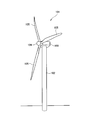
- FIG. 1 is a view for explaining an embodiment of the present invention, and is a perspective view of a windmill.
- FIG. 2 is a cross-sectional view showing a part of the tower and nacelle of the windmill shown in FIG.
- FIG. 3 is a plan view showing the arrangement of the driving device in the movable part shown in FIG.
- FIG. 4 is a side view of the drive device shown in FIG. 2, partially showing a cross-sectional state.
- FIG. 5 is a view showing an installation part of the drive device shown in FIG. 2, partially showing a cross-sectional state.
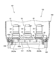
- FIG. 6 is a diagram schematically showing a braking mechanism of the drive device shown in FIG.
- FIG. 7 is a block diagram for explaining a functional configuration of the control device.
- FIG. 1 is a perspective view of the windmill 101.
- FIG. 2 is a cross-sectional view showing a part of the tower 102 and the nacelle 103.
- the driving device 10 has an outer shape, not a cross section.
- FIG. 3 is a plan view showing the arrangement of the driving device 10 in the movable part shown in FIG.
- FIG. 4 is a view of the driving device 10 as viewed from the side, and a partial cross-sectional state is shown.
- FIG. 5 is a view showing an installation part of the driving device 10, and a partial cross-sectional state is shown.
- FIG. 6 is a diagram illustrating a braking mechanism of the driving device 10 and shows a cross-sectional state.
- the driving device 10 drives a nacelle 103 that is rotatably installed with respect to the tower 102 of the windmill 101, or a blade 105 that is installed so as to be swingable in the pitch direction with respect to a rotor 104 attached to the nacelle 103.
- the driving device 10 can be used as a yaw driving device that performs yaw driving so as to rotate the nacelle 103 with respect to the tower 102, and further, pitch driving so as to rotate the shaft portion of the blade 105 with respect to the rotor 104. It can also be used as a pitch driving device for performing the above.
- the driving device 10 is used as a yaw driving device will be exemplified, but the present invention can be similarly applied to the case where the driving device 10 is used as a pitch driving device.
- the windmill 101 includes a tower 102, a nacelle 103, a rotor 104, a blade 105, and the like.
- the tower 102 extends vertically upward from the ground.
- the nacelle 103 is rotatably installed with respect to the upper part of the tower 102.
- the rotation of the nacelle 103 with respect to the tower 102 is a yaw rotation about the longitudinal direction of the tower 102 as a rotation center.
- the nacelle 103 is driven by the plurality of driving devices 10 and rotates with respect to the tower 102.
- the rotor 104 is connected to the power transmission shaft and is rotatable with respect to the nacelle 103.
- a plurality of blades 105 (three in the example shown in FIG. 1) are provided, and each blade 105 extends from the rotor 104 in a radial direction around the rotation axis of the rotor 104 with respect to the nacelle 103. To do.
- the plurality of blades 105 are arranged at an equal angle to each other.
- each blade 105 is rotatable in the pitch direction. That is, each blade 105 is rotatable with respect to the rotor 104 about its longitudinal direction.
- the connection part of each blade 105 with the rotor 104 is a movable part, and each blade 105 and the rotor 104 can relatively rotate.
- the blade 105 is rotationally driven by a driving device provided as a pitch driving device, and the driving device as the pitch driving device can be configured similarly to the driving device 10 as a yaw driving device described later.
- the nacelle 103 is rotatably installed at the bottom 103 a with respect to the top of the tower 102 via a bearing 106.
- a ring gear 107 having inner teeth formed on the inner periphery is fixed to the upper portion of the tower 102.
- the teeth of the ring gear 107 are not limited to the inner teeth provided on the inner periphery thereof, and may be external teeth provided on the outer periphery thereof. In each drawing, the illustration of each tooth of the ring gear 107 is omitted.
- each driving device 10 includes an electric motor 23 including a motor driving unit and a motor braking unit, which will be described later, and a speed reducing unit 25 to which power from the electric motor 23 (particularly, the motor driving unit) is transmitted. To do.
- the motor driving unit outputs driving force (rotational power), and the motor braking unit can brake the motor driving unit to reduce the driving force (rotational power) output from the motor driving unit.
- the term “braking” used herein is interpreted in a broad sense, and the definition of braking includes maintaining the stopped state of what is stopped and stopping what is moving.
- each driving device 10 By driving each driving device 10 having such a configuration, the nacelle 103 (first structure) that is one of the movable parts of the windmill 101 is replaced with the tower 102 (second structure) that is the other movable part of the windmill 101. Can be rotated.
- a sufficiently large driving force can be secured, and the heavy nacelle 103 can be appropriately rotated with respect to the tower 102.
- Each driving device 10 operates based on a control signal sent from a control device 110 (control means; see FIG. 7), which will be described later, to the electric motor 23 (motor driving unit and motor braking unit).
- the plurality of driving devices 10 collectively constitute a driving device unit 9.
- the wind turbine drive system 5 is configured by the drive device 10 and the control means 110.
- the ring gear 107 is formed in a circumferential shape and has a central axis Cm.
- the nacelle 103 rotates around the central axis Cm of the ring gear 107.
- the center axis Cm of the ring gear 107 coincides with the longitudinal direction of the tower 102.
- the direction parallel to the central axis Cm of the ring gear 107 is also simply referred to as “axial direction dl”.
- Each driving device group includes three driving devices 10.
- a total of six drive devices 10 included in the pair of drive device groups constitute the drive device unit 9.
- the drive device body 20 is disposed along a circumference cl1 (see FIG. 3) centering on the central axis Cm of the ring gear 107.
- the three driving devices 10 included in each driving device group are arranged at a constant interval along the circumference cl1.
- Each drive device 10 includes a drive device body 20 having a drive gear 24a that meshes with the ring gear 107, and an abnormality detection unit 80 that monitors the state of the drive device body 20 and detects an abnormality.
- the drive device main body 20 is fixed to the nacelle 103.
- each driving device 10 has a nacelle 103 (first structure) via a fastener 30 disposed so as to pass through a through hole 22 a formed in the flange 22 of the driving device body 20. It is fixed to.
- the drive device body 20 includes an output shaft 24 having a drive gear 24 a that meshes with the ring gear 107, a case 21 that rotatably holds the output shaft 24, and an electric motor 23 that is fixed to the case 21.
- the drive device main body 20 further includes a speed reduction unit 25 housed in the case 21 and connecting the electric motor 23 and the output shaft 24.
- the speed reduction unit 25 increases the torque while decelerating the input (rotational power) from the electric motor 23 and transmits it to the output shaft 24.
- the specific configuration of the speed reduction unit 25 is not particularly limited, but typically, an eccentric oscillating gear type reduction mechanism, a planetary gear type reduction mechanism, or an eccentric oscillating gear type and a planetary gear type are used.
- a combined speed reduction mechanism can be employed in the speed reduction unit 25.
- the end of the output shaft 24 on the side away from the speed reduction portion 25 extends from the case 21, and a drive gear 24 a is formed at this extended portion of the output shaft 24.
- the output shaft 24 passes through a through hole 103 b formed in the bottom 103 a of the nacelle 103 and meshes with the ring gear 107.
- the drive gear 24 a has a shape corresponding to the ring gear 107.
- the drive gear 24 a can be formed as a pinion gear having external teeth that mesh with the internal teeth of the ring gear 107.
- the drive device 10 has a longitudinal axis that coincides with the rotational axis Cr of the output shaft 24. In a state where the driving device 10 is fixed to the nacelle 103, the rotation axis Cr of the output shaft 24 is parallel to the axial direction dl of the windmill 101.
- the case 21 is formed in a cylindrical shape as shown in FIG. 4, and is arranged so that its longitudinal axis is located on the rotation axis Cr as shown in FIG.
- the case 21 is open at both ends along the rotation axis Cr.
- the drive gear 24a of the output shaft 24 is exposed from the opening of the case 21 on the tower 102 side.
- An electric motor 23 is attached to the opening of the case 21 opposite to the tower 102.
- the case 21 has a flange 22, and the flange 22 of this example is formed in an annular shape as shown in FIG. 3, and extends along a circumference cl ⁇ b> 3 centering on the rotation axis Cr of the output shaft 24. As shown in FIGS.
- the flange 22 has a through hole 22 a extending in the axial direction dl.
- a large number of through holes 22a are formed on a circumference cl3 centered on the rotation axis Cr of the output shaft 24. In the illustrated example, twelve through holes 22a are formed.
- the fastener 30 passes through the flange 22 through the through hole 22a formed in the flange 22 of the drive device main body 20.
- the fastener 30 has a bolt 30a and a nut 30b.
- the bolt 30 a passes through the flange 22 of the drive device main body 20 and the bottom 103 a of the nacelle 103.
- the nut 30b is screwed to the bolt 30a from the tower 102 side.
- the fastener 30 configured by the combination of the bolt 30a and the nut 30b is provided for each through hole 22a of the drive device main body 20.
- each drive device main body 20 is attached to the nacelle 103 at 12 locations by 12 fasteners 30.
- the fastener 30 is not limited to the illustrated example.
- a female screw that can be screwed with the male screw of the bolt 30 a may be formed in the through hole of the nacelle 103.
- the fastener 30 is constituted by a bolt 30 a, and the drive device main body 20 can be fixed to the nacelle 103 by the male screw of the bolt 30 a meshing with the female screw of the through hole of the nacelle 103.
- the electric motor 23 includes a motor driving unit 48 and a motor braking unit 50.
- FIG. 6 is a diagram schematically showing a partial cross section of the electric motor 23.
- the motor braking unit 50 is a braking mechanism that brakes the rotation transmitted to the drive gear 24a.
- the drive device body 20 can brake the rotation transmitted to the drive gear 24a or the rotation output from the drive gear 24a instead of or in addition to the motor braking unit 50. It can have various forms of braking mechanisms.
- the electric motor 23 including the motor driving unit 48 and the motor braking unit 50 is provided for each driving device 10, and one motor braking unit 50 is attached to one motor driving unit 48.
- the motor drive unit 48 can be configured by any device capable of controlling the rotation speed of the drive shaft 48a based on a command from the control device 110 (see FIG. 7).
- the illustrated motor braking unit 50 brakes the rotation of the driving shaft 48a of the motor driving unit 48 or releases the braking of the driving shaft 48a based on a command from the control device 110 (see FIG. 7). As a mechanism. In a state where the rotation of the drive shaft 48a is braked, the rotation speed of the drive shaft 48a is reduced, and finally the rotation of the drive shaft 48a can be completely stopped.
- the drive shaft 48a is basically not braked by the motor braking unit 50, and is basically the original according to the electric power supplied to the motor driving unit 48. It can be rotated according to the number of rotations.
- the driving force (rotational power) from the drive shaft 48 a of the motor drive unit 48 is transmitted to the output shaft 24 via the speed reduction unit 25.
- the motor braking unit 50 of this example is attached to the end of the cover 72 of the motor driving unit 48 opposite to the speed reduction unit 25, and includes a housing 51, a friction plate 56, an armature 57, an elastic member 55, an electromagnet 53. And a first friction plate connecting portion 77 and the like.
- the housing 51 is a structural body that houses the friction plate 56, the armature 57, the elastic member 55, the electromagnet 53, the first friction plate coupling portion 77, and the like, and is fixed to the cover 72 of the motor driving unit 48.
- the friction plate 56 is coupled to the drive shaft 48 a of the motor drive unit 48 via the first friction plate coupling unit 77. In the through hole of the friction plate 56, one end of the drive shaft 48a is disposed so as to penetrate therethrough.
- the first friction plate connecting portion 77 of this example has a spline shaft 77a and a slide shaft 77b.
- the spline shaft 77a is fixed to the outer periphery of one end portion of the drive shaft 48a by key coupling by a key member (not shown) and engagement by a stopper ring 77c.
- the slide shaft 77b is attached to the spline shaft 77a so as to be slidable in the axial direction.
- the first friction plate connecting portion 77 is provided with a spring mechanism (not shown) for positioning the position of the slide shaft 77b in the axial direction with respect to the spline shaft 77a at a predetermined position.
- the inner periphery of the friction plate 56 is fixed to the outer peripheral edge of the flange-shaped portion of the slide shaft 77b, and the friction plate 56 is integrally coupled to the slide shaft 77b.
- the motor braking unit 50 having the above configuration, when the drive shaft 48a rotates, the spline shaft 77a, the slide shaft 77b, and the friction plate 56 also rotate together with the drive shaft 48a.
- the slide shaft 77b and the friction plate 56 held so as to be slidable in the axial direction with respect to the drive shaft 48a and the spline shaft 77a are moved in the axial direction of the spline shaft 77a by a spring mechanism. Is positioned at a predetermined position.
- the friction plate 56 disposed at the predetermined position is separated from an armature 57 and a friction plate 58 which will be described later.
- the armature 57 is provided so as to be able to come into contact with the friction plate 56 and is provided as a member that generates a braking force for braking the rotation of the drive shaft 48 a by coming into contact with the friction plate 56.
- a friction plate 58 is provided at a position facing one of the ends of the cover 72 of the motor driving unit 48 that faces the friction plate 56. The friction plate 58 is installed at a position where it can contact the friction plate 56.
- the elastic member 55 is held by an electromagnet body 53a of an electromagnet 53 described later, and biases the armature 57 from the electromagnet 53 side toward the friction plate 56 side.
- the plurality of elastic members 55 of the present example are arranged in the circumferential direction in the electromagnet main body 53a in two arrangements on the inner peripheral side and the outer peripheral side in a concentric manner around the drive shaft 48a.
- positioning form of the above-mentioned elastic member 55 is only an illustration, and the elastic member 55 may take another arrangement
- the electromagnet 53 includes an electromagnet main body 53a and a coil portion 53b, and separates the armature 57 from the friction plate 56 by attracting the armature 57 with a magnetic force.
- the electromagnet main body 53 a is fixed to the housing 51 at the end opposite to the side facing the armature 57.
- the electromagnet main body 53a is provided with a plurality of elastic member holding holes 53c that open toward the armature 57, and the elastic member 55 is disposed in each of the elastic member holding holes 53c.
- the coil part 53b is installed inside the electromagnet main body 53a and is arranged in the circumferential direction of the electromagnet main body 53a. Supply and interruption of current to the coil unit 53b are performed based on a command from the control device 110.
- the electromagnet 53 is energized based on a command from the control device 110.
- the electromagnet 53 is energized and excited, the armature 57 is attracted to the coil portion 53b by the magnetic force generated in the electromagnet 53.
- the armature 57 is attracted to the electromagnet 53 against the elastic force (spring force) of the plurality of elastic members 55.
- the armature 57 is separated from the friction plate 56, and the braking of the drive shaft 48a is released. Therefore, in a state where the electromagnet 53 is excited and the braking of the drive shaft 48a is released, the armature 57 is in contact with the electromagnet main body 53a.
- FIG. 6 shows a state where the electromagnet 53 is demagnetized and the rotation of the drive shaft 48a is braked.
- the friction plate 56 is also in contact with the friction plate 58 by the biasing force acting from the armature 57. Therefore, when the electromagnet 53 is demagnetized, the friction plate 56 is sandwiched between the armature 57 and the friction plate 58 by the urging force from the plurality of elastic members 55. Thereby, the rotation of the drive shaft 48a is braked by the frictional force generated between the armature 57 and the friction plate 56 and the frictional force generated between the friction plate 56 and the friction plate 58.
- the abnormality detection unit 80 that detects the abnormality by monitoring the state of the drive device body 20 having the above configuration will be described.
- the abnormality detection unit 80 monitors the force generated between the ring gear 107 and the drive gear 24a, the state of the drive device main body 20, and the operation of the braking mechanism (motor braking unit 50).
- the abnormality detection unit 80 includes a load sensor 81, an oil sensor 82, and a braking mechanism sensor 83.
- each of the sensors 81, 82, and 83 will be described.
- the load sensor 81 detects the force generated at the meshing portion between the ring gear 107 and the drive gear 24a.
- the load sensor 81 can be configured by various sensors that can acquire an index related to the force generated in the meshing portion. Therefore, the load sensor 81 directly or indirectly detects the force generated at the meshing portion.
- the load sensor 81 is configured as a sensor that measures a change in the state of the fastener 30.
- the fastener 30 is a member that fixes the drive device body 20 to the nacelle 103. Therefore, the state change of the fastener 30 is linked to the generation of force (load) on the meshing portion between the ring gear 107 and the drive gear 24a. For this reason, the magnitude of the stress (load) between the drive gear 24 a and the ring gear 107 can be detected by detecting the amount of state change of the fastener 30.
- the load sensor 81 is configured by a known sensor that measures one or more of the load applied to the fastener 30, the displacement of the fastener 30 with respect to the nacelle 103, and the relative position of the fastener 30 with respect to the nacelle 103. Can be done.
- an axial force sensor is used as the load sensor 81, and a load (axial force) in a specific direction applied to the fastener 30 can be measured.
- the load sensor 81 is fixed and held with respect to one of the movable parts, that is, the nacelle 103, using a jig 49.
- the axial force sensor that constitutes the sensor 40 abuts against the head of the bolt 30 a that constitutes the fastener 30.
- the present invention is not limited to this example, and the load sensor 81 may abut against the tip of the bolt 30a opposite to the head as shown by a two-dot chain line in FIG. 5, or the sensor 40 may contact the nut 30b. You may touch.
- the sensor 40 may detect a load applied to a fastening bolt that fastens the nacelle 103 and the case 21.
- a strain gauge as the load sensor 81, it is possible to measure the stress applied to the fastener.
- a magnetic sensor or photoelectric sensor as the load sensor 81, the position and displacement of the fastener 30 can be measured in a non-contact manner.
- the driving force is output from the driving device main body 20 of the other driving device 10 with the target driving device 10 stopped.
- an excessive force may be generated between the drive gear 24 a of the target drive device 10 and the ring gear 107.
- the target drive device 10 is stopped, an abnormality cannot be detected even if the control current of the drive device 10 is monitored.
- the load sensor 81 detects the force generated at the meshing portion between the ring gear 107 and the drive gear 24a. Therefore, by using the detection result of the load sensor 81, it is possible to effectively avoid damage to the drive device body 20 and damage to the ring gear 107 and its surrounding structures that may cause serious damage.
- the drive device main body 20 includes a mechanism such as a speed reduction unit 25 configured as, for example, an eccentric oscillating gear type reduction mechanism or a planetary gear type reduction mechanism. Therefore, the case 21 that houses the mechanism such as the speed reduction unit 25 is usually filled with oil that functions as lubricating oil.
- the state of the oil inside the drive device main body 20 accurately reflects the state of the internal mechanism of the drive device main body 20. As shown in FIG. 4, at least the sensing portion of the oil sensor 82 is disposed in the oil.
- the oil sensor 82 monitors the state of oil used in the drive device body 20, for example, the color of the oil and the water content.
- the oil sensor 82 can diagnose aged deterioration of the drive device body 20. Therefore, by using the detection result of the oil sensor 82, it is possible to effectively avoid damage to the drive device body 20 and damage to the ring gear 107 and its surrounding structures that may cause serious damage.
- the state monitoring sensor for monitoring the state of the drive device body 20 is not limited to the oil sensor 82.
- the state monitoring sensor may include a camera that images the components included in the drive device main body 20 instead of or in addition to the oil sensor 82, or the components included in the drive device main body 20.
- a displacement sensor that monitors the displacement of the drive device 20 may be included, or a sensor that monitors a load generated in a component included in the drive device main body 20 may be included.
- the braking mechanism sensor 83 monitors the operation of the braking mechanism.
- the braking mechanism is a mechanism that brakes the rotation transmitted to the drive gear 24a or the rotation output from the drive gear 24a.
- the braking mechanism is configured by a motor braking unit 50.
- the motor braking unit 50 is incorporated in the electric motor 23 and has an armature 57 that operates based on a control signal from the control device 110.
- the braking mechanism sensor 83 monitors the position of the armature 57 along the axial direction dl.
- the braking mechanism sensor 83 shown in FIG. 6 detects the position and displacement of the detected portion 83b attached to the armature 57 and the detected portion 83b in a direction parallel to the axial direction dl.
- a detection unit 83a detects the position and displacement of the detected portion 83b attached to the armature 57 and the detected portion 83b in a direction parallel to the axial direction dl.
- the detected portion 83 b of this example is provided as a permanent magnet and is fixed to the armature 57, and is particularly attached to the electromagnet 53 side portion of the outer peripheral portion of the armature 57.
- the detection unit 83 a is provided as a sensor that can detect the position and displacement of the detected unit 83 b that is displaced together with the armature 57.
- the detection unit 83a detects the position and displacement of the detected unit 83b in the direction parallel to the rotation axis Cr of the drive shaft 48a, thereby detecting the position of the armature 57 in the direction parallel to the rotation axis Cr of the drive shaft 48a.
- the amount of displacement can be detected.
- the illustrated detection unit 83 a is provided as a magnetic sensor that measures the strength and direction of the magnetic field (magnetic field) provided by the detected unit 83 b that is a permanent magnet, and is fixed to the inner wall of the housing 51.
- the detection unit 83a detects the position and displacement of the detected unit 83b by measuring the strength and direction of the magnetic field (magnetic field) provided by the detected unit 83b. Therefore, it is preferable that the detection part 83a is fixed to the housing 51 at a position corresponding to the detected part 83b with respect to a direction parallel to the rotation axis Cr of the drive shaft 48a.
- the motor braking unit 50 constituting the braking mechanism can detect an abnormal state in which the armature 57 is malfunctioning due to the fixing of the armature 57 or the like. For example, if a strong wind blows in a state where the braking mechanism is abnormal and the operation of the drive gear 24a is restricted, an excessive force may be generated at the meshing portion between the drive gear 24a and the ring gear 107. Such a situation cannot be detected by the prior art that monitors the control current. Further, in a movable part where a plurality of driving devices 10 are used as in the illustrated example, other driving is performed in a state where the braking mechanism of the target driving device 10 is abnormal and the operation of the driving gear 24a is restricted.
- the braking mechanism sensor 83 monitors the operation of the motor braking unit 50 that forms the braking mechanism. Therefore, by using the detection result of the braking mechanism sensor 83, it is possible to effectively avoid damage to the drive device body 20 and damage to the ring gear 107 and its surrounding structures that may cause serious damage. .
- the driving force is restricted by the operation. It acts as an external force on the meshing portion between the drive gear 24a and the ring gear 107. Then, the drive device main body 20 and the ring gear 107 may be damaged within an extremely short time such as only a few milliseconds from the output of the drive force acting as an external force. Such damage cannot be effectively avoided by monitoring the control current.
- the braking mechanism sensor 83 it is possible to detect an abnormality in the motor braking unit 50 that constitutes the braking mechanism. Therefore, it is possible to predict the occurrence of an excessive load on the meshing portion from the detection result of the braking mechanism sensor 83, and to effectively avoid the damage.
- each drive device 10 includes a separate abnormality detection unit 80, and an abnormality is detected for each drive device 10.
- FIG. 7 is a block diagram for explaining a functional configuration of the control device 110.
- the control device 110 receives detection results from each of the abnormality detection units 80 provided in the plurality of drive devices 10 (six drive devices 10 in this example). That is, the load sensor 81, the oil sensor 82, and the brake mechanism sensor 83 that constitute the abnormality detection unit 80 of each drive device 10 are each connected to the control device 110.
- the control device 110 can output a control signal for controlling the motor driving unit 48 and the motor braking unit 50 provided in each driving device 10.
- the installation position of the control device 110 is not particularly limited, and may be provided integrally with each element (for example, the tower 102, the nacelle 103, the rotor 104, the blade 105, or the like) constituting the wind turbine 101, and May be provided separately.
- the control device 110 stops the output of the driving force from the drive gear 24a of the drive device main body 20 of the drive device 10 to the ring gear 107 when the abnormality detection unit 80 of any of the drive devices 10 detects an abnormality. Stopping the driving force from the driving gear 24 a can be typically achieved by cutting off the power supply to the electric motor 23 by the control device 110. By stopping the output from the drive gear 24a to the ring gear 107 while an excessive force is applied to the meshing portion between the drive gear 24a and the ring gear 107, further increase in the load on the meshing portion can be avoided. Can do.
- the control device 110 releases the braking of the rotation by the braking mechanism (motor braking unit 50) of the drive device 10. That is, when the abnormality detection unit 80 detects an abnormality, the control device 110 sends a control signal so as to release the braking of the rotation by the braking mechanism (the motor braking unit 50).
- the release of the rotational braking of the motor braking unit 50 can be realized by supplying electric power to the motor braking unit 50 by the control device 110.
- the load at the meshing portion between the drive gear 24a and the ring gear 107 becomes excessive. End up. For this reason, when the abnormality detection unit 80 detects an abnormality, the brake of the rotation by the braking mechanism (motor braking unit 50) of the drive device 10 is released, thereby not only avoiding an increase in load at the meshing unit. In addition, the load generated in the meshing portion can be released.
- the control device 110 stops outputting the driving force from the driving gear 24a to the ring gear 107 in the one driving device, Also in drive devices other than the one drive device, output of the drive force from the drive gear 24a to the ring gear 107 is stopped.
- the control device 110 performs a braking mechanism (releases rotational braking by the motor braking unit 50) in the one drive device 10, The rotational braking by the braking mechanism is also released in a driving device other than one driving device.As described above, when a plurality of driving devices 10 are provided in one movable part, the driving gear of one driving device 10 is provided.
- the driving force output from 24a to the ring gear 107 acts as an external force on the meshing portion between the driving gear 24a and the ring gear 107 of the other driving device 10. Therefore, if any abnormality is found, The driving force of the driving device 10 is avoided from being applied to the meshing part between the other driving device 10 and the ring gear 107 as an external force, and the braking force by the braking mechanism To enable each drive device 10 to operate flexibly in response to an external force, thereby more effectively damaging the drive device body 20 and the ring gear 107 connected to the drive device body 20. And damage around it can be avoided.
- Free yaw control is control that allows free relative rotation between the nacelle 103 (first structure) and the tower 102 (second structure), and is a control that can inhibit free relative rotation between the nacelle 103 and the tower 102. Power and driving force are reduced or released.
- the control device 110 cuts off the energization to the motor driving unit 48 to stop the rotational drive of the drive shaft 48a, and the motor braking unit 50. Is controlled so that a braking force is not applied from the motor braking unit 50 to the motor driving unit 48 (that is, the driving shaft 48a).
- the control device 110 controls such other driving means and braking means to inhibit free relative rotation between the nacelle 103 and the tower 102. Eliminate possible braking and driving forces.
- a brake device such as a caliper brake that directly brakes the rotational movement of the ring gear 107
- the control device 110 controls the brake device to control the ring gear from the ring gear. A braking force is not applied to 107.
- each drive device 10 When the control device 110 performs the free yaw control as described above, the drive gear 24a and the ring gear 107 of each drive device 10 are placed in a freely rotatable state, and the nacelle 103 freely rotates with respect to the tower 102. be able to. Such free rotation can effectively prevent an excessive load between each drive gear 24a and the ring gear 107, such as damage to each element constituting the drive device 10 and the ring gear 107. Problems can be avoided in advance.
- the driving device 10 is installed in one structure in the movable part of the windmill 101 and is engaged with the ring gear 107 installed in the other structure in the movable part of the windmill 101.
- an abnormality detection unit 80 that monitors at least one of the force generated between the ring gear 107 and the drive gear 24a and the state of oil in the drive device main body 20. And when the abnormality detection part 80 detects abnormality, the output to the ring gear 107 from the drive gear 24a of the drive device main body 20 is stopped.
- the abnormality detection unit 80 applies not only an abnormality in which the output from the drive device body 20 is excessive, but also a large external force, for example, an abnormality in which the control current of the drive device body 20 is excessive.
- the abnormality detection unit 80 can detect an abnormality in a state where the output of the driving force from the driving device main body 20 is stopped, and can effectively cope with an instantaneous damage to the driving device 10, the ring gear 107, and the like. it can.
- the drive device body 20 includes a braking mechanism (motor braking unit 50) that brakes the rotation transmitted to the drive gear 24a or the rotation output from the drive gear 24a.
- the abnormality detection unit 80 also monitors the operation of the braking mechanism 50. That is, a state in which the operation of the drive gear 24a and the ring gear 107 at the meshing part is unintentionally restricted due to an abnormality in the braking mechanism 50 is detected, and the abnormality is detected from the drive gear 24a to the ring gear 107. It is avoided that the driving force is output at the same time. Accordingly, it is possible to effectively prevent an excessive external force from being applied to the meshing portion and an excessive control current of the driving device 10 from occurring. Thereby, it is possible to effectively avoid damage to the drive device, the ring gear, and the like.
- the drive device main body 20 includes a braking mechanism (motor braking unit 50) that brakes the rotation transmitted to the drive gear 24a or the rotation output from the drive gear 24a.
- a braking mechanism (motor braking unit 50) that brakes the rotation transmitted to the drive gear 24a or the rotation output from the drive gear 24a.
- the abnormality detection unit 80 detects an abnormality
- the rotational braking by the braking mechanism (motor braking unit 50) is released.
- an excessive external force is applied to the meshing portion without excessive control current while the operation of the driving gear 24 a and the ring gear 107 at the meshing portion is restricted by the braking mechanism 50. Can be effectively avoided. Thereby, it can avoid effectively that a drive device, a ring gear, etc. will be damaged.
- the driving device 10 is installed in one structure in the movable part of the windmill 101 and is engaged with the ring gear 107 installed in the other structure in the movable part of the windmill 101.
- 24a and drive device body 20 having a braking mechanism (motor braking unit 50) for braking the rotation transmitted to drive gear 24a or the rotation output from drive gear 24a, and abnormality detection for monitoring the operation of braking mechanism 50 Part 80.
- the abnormality detection part 80 detects abnormality, the output to the ring gear 107 from the drive gear 24a of the drive device main body 20 is stopped.
- the abnormality detection unit 80 can detect a state in which the rotation of the drive gear 24 a is braked due to an abnormality in the braking mechanism 50.
- the abnormality detection unit 80 can detect a state in which the operation at the meshing portion between the drive gear 24a and the ring gear 107 is restricted.
- the output of the driving force from the drive device body 20 is stopped (restricted), so that the drive device 10 does not depend on whether or not the control current of the drive device 10 becomes excessive. Damage to the ring gear 107 and its surroundings can be effectively avoided.
- the output of the driving force is started from the drive device body 20 in a state where the operation of the meshing portion is restricted, the drive device 10 and the ring gear 107 may be momentarily damaged.
- the restraint between the drive gear 24a and the ring gear 107 at the meshing portion caused by the abnormality of the brake mechanism 50 is detected in a state where the output of the drive force from the drive device main body 20 is stopped. Can do. Then, when the output of the driving force from the drive device main body 20 is stopped, the abnormality detection unit 80 detects an abnormality, so that the instantaneous damage to the drive device 10 and the ring gear 107 can be effectively dealt with. be able to.
- the abnormality detection unit 80 when the abnormality detection unit 80 detects an abnormality, the rotational braking by the braking mechanism (motor braking unit 50) is released.
- the abnormality detection unit 80 can detect a state in which the operation of the meshing unit is unintentionally restricted due to an abnormality of the braking mechanism 50, and can eliminate this unintended restriction. Accordingly, an excessive external force is applied to the meshing portion in an unintentionally restricted state of the operation of the drive gear 24a and the ring gear 107 at the meshing portion, and as a result, the drive device 10 does not have an excessive control current. It is possible to effectively prevent the ring gear 107 and the like from being damaged.
- the windmill 101 and the drive unit 9 include a plurality of drive units 10 provided in one movable part.
- the abnormality detection unit 80 is provided separately for each driving device 10.
- the driving gear 24 a of one driving device 10 whose operation is restrained by the braking mechanism 50 is engaged with the engaging portion of the driving gear 24 a and the ring gear 107 from the driving gear 24 a of the other driving device 10.
- the driving force output to the ring gear 107 acts as an external force.
- the braking force that restrains the pressure acts as an external force.
- the drive gear 24a to the ring gear 107 is provided in the drive device 10 provided with the one abnormality detection unit 80.
- the driving force output is stopped, and the driving force output from the driving gear 24a to the ring gear 107 is also stopped in the driving devices 10 other than the driving device 10 provided with the one abnormality detecting unit 80. It has become. Therefore, it is possible to effectively avoid that the above-described operational effects are more remarkably exhibited and the drive device 10 and the ring gear 107 are damaged.
- the windmill 101 and the drive unit 9 include a plurality of drive units 10 provided in one movable part.
- the abnormality detection unit 80 is provided separately for each driving device 10.
- the driving gear 24 a of the other driving device 10 is engaged with the meshing portion of the driving gear 24 a and the ring gear 107 of one driving device 10 whose operation is restricted by the braking mechanism 50.
- the driving force output to the ring gear 107 acts as an external force.
- the operation of the drive gear 24a and the ring gear 107 by the braking mechanism 50 of the other drive device 10 with respect to the meshing portion of the drive gear 24a and the ring gear 107 of one drive device 10 outputting the driving force.
- the force that restrains acts as an external force.
- the rotational braking by the braking mechanism 50 is released in the drive device 10 provided with the one abnormality detection unit 80.
- the rotational braking by the braking mechanism 50 is also released in the drive devices other than the drive device 10 provided with the one abnormality detection unit 80. Therefore, it is possible to effectively avoid that the above-described operational effects are more remarkably exhibited and the drive device 10 and the ring gear 107 are damaged.
- the abnormality detection unit 80 includes the load sensor 81, the oil sensor 82, and the braking mechanism sensor 83 .
- the present invention is not limited to the above-described example, and the abnormality detection unit 80 may include any one or more of the load sensor 81, the oil sensor 82, and the braking mechanism sensor 83. Further, the abnormality detection unit 80 may include other sensors in addition to any one or more of the load sensor 81, the oil sensor 82, and the braking mechanism sensor 83. An anemometer can be illustrated as another sensor.
- the anomaly detector 80 further includes an anemometer that detects the degree of gust that can act on the meshing portion as an external force, and when the wind speed measured by the anemometer becomes a predetermined value or more, the drive device main body The driving force output from the 20 driving gears 24a to the ring gear 107 may be stopped. Further, when the wind speed measured by the anemometer becomes equal to or higher than a predetermined value, the rotational braking by the braking mechanism 50 may be released.
- the abnormality detection unit 80 may include a sensor that monitors the control current of the electric motor 23. That is, when the control current of the electric motor 23 becomes excessive, the output of the driving force from the driving gear 24a of the driving device body 20 to the ring gear 107 may be stopped. Further, when the control current of the electric motor 23 becomes excessive, the rotational braking by the braking mechanism 50 may be released.
- the load sensor 81 is not limited to a sensor that detects the state quantity of the fastener 30, and any state quantity that varies depending on the magnitude of “force generated between the drive gear 24 a and the ring gear 107”. It can be configured by sensors that can detect.
- a sensor that can measure the amount of force acting on the speed reduction unit 25 (for example, a sensor that detects distortion generated in the speed reduction unit 25) is installed in the speed reduction unit 25 of each driving device 10, and the sensor is used as the load sensor 81. May be.
- the abnormality detection unit 80 detects an abnormality
- the example in which the output of the driving force is stopped by stopping the power supply to the electric motor 23 has been described.
- a clutch mechanism 85 (see FIG. 4) that switches between transmission and disconnection of power is provided between the electric motor 23 and the speed reduction unit 25, and when an abnormality is detected, the clutch mechanism 85 is released and the electric motor 23
- the output of the driving force from the drive gear 24a to the ring gear 107 may be stopped by interrupting the power transmission to the speed reduction unit 25.
- the braking mechanism is configured as the motor driving unit 48 that is incorporated in the electric motor 23 and brakes the rotation of the driving shaft 48a of the motor driving unit 48 is shown.
- the present invention is not limited to this example, and the braking mechanism may be a mechanism that brakes one or more of the components included in the speed reduction unit 25, the output shaft 24, and the drive gear 24a.
- the abnormality detection unit 80 detects an abnormality
- the interlocking between the component that is rotationally braked by the braking mechanism 50 and the drive gear 24a may be released.
- a clutch mechanism 85 see FIG. 4
- the interlock between the drive shaft 48a and the drive gear 24a may be cut off. Also by such a modification, the same effect as one embodiment mentioned above can be produced.
Abstract
[課題]駆動装置とリングギアとの噛み合い部に過大な力が生じた結果として駆動装置及びリングギアの少なくとも一方が破損してしまうことを効果的に防止する。 [解決手段]駆動装置10は、風車101の可動部分における一方の構造体に設置され且つ風車101の可動部分における他方の構造体に設置されたリングギア107と噛み合う駆動ギア24aを有する駆動装置本体20と、リングギアと駆動ギアとの間に発生する力および駆動装置本体の状態の少なくとも一方を監視する異常検出部80と、を備える。異常検出部が異常を検出した場合、駆動装置本体の駆動ギアからリングギアへの出力が停止される。
Description
本発明は、風車の可動部分に用いられる駆動装置及び駆動装置ユニット、並びに、風車に関する。
例えばJP2015-140777Aに開示されているように、風力発電装置として用いられる風車として、タワーの上部に回転自在に設置されて内部に発電機等が配置されるナセルと、ナセルに設けられたロータ(ハブ、主軸部)に対して回転自在に設置されたブレード(羽根)と、を備えるものが知られている。この風車は、風車の可動部分における一方の構造体を他方の構造体に対して回転させるように駆動する駆動装置として、ヨー駆動装置或いはピッチ駆動装置等を有している。ヨー駆動装置は、風向きに応じて、一方の構造体であるナセルを他方の構造体であるタワーに対して回転させる。ピッチ駆動装置は、一方の構造体であるブレードの軸部を他方の構造体であるナセル側のロータに対して回転させて、ブレードのピッチ角を調節する。
ところで、駆動装置自体の劣化や突風等に起因して、駆動装置の出力部をなす駆動ギアおよび駆動ギアと噛み合うリングギアとの噛み合い部に大きな力が発生してしまう。また、風車の一つの可動部分には、通常、複数の駆動装置が設けられる。そして、複数の駆動装置のうちの一つに異常が生じた場合、いずれかの駆動装置の駆動ギアとリングギアとの噛み合い部に高負荷が生じやすくなる。噛み合い部に発生する力が大きくなると、駆動装置またはリングギアが破損する。駆動装置が破損した場合には、当該駆動装置の一部又は全体を取り替える必要が生じる。一方、リングギア又は構造体のリングギア周囲が破損した場合、大規模な修復工事が必要となり、長期間にわたって風車の操業を停止することになる。
このような不具合に対処するため、JP2015-140777Aでは、駆動装置の制御電流が定格値を超えた場合に、駆動装置から駆動ギアを脱落させることを提案している。しかしながら、例えば、突風が吹いた場合には、駆動装置が停止して制御電流が流れていなくても、当該駆動装置とリングギアとの噛み合い部に大きな力が生じる。また、高負荷が生じて破損に至るまでの時間が数ミリ秒といった極めて短い場合もある。このような破損は、制御電流の監視だけでは破損の発生を回避することができない。
本発明は、以上の点を考慮してなされたものであって、駆動装置とリングギアとの噛み合い部に過大な力が生じた結果として駆動装置及びリングギアの少なくとも一方が破損してしまうことを効果的に防止することを目的とする。とりわけ本発明は、制御電流の監視だけでは十分に回避することができない破損を効果的に回避し得るようにすることを目的とする。
本発明による駆動装置は、
風車の可動部分における一方の構造体に設置され且つ前記風車の可動部分における他方の構造体に設置されたリングギアと噛み合う駆動ギアを有する駆動装置本体と、
前記リングギアと前記駆動ギアとの間に発生する力および前記駆動装置本体の状態の少なくとも一方を監視する異常検出部と、を備え、
前記異常検出部が異常を検出した場合、前記駆動装置本体の前記駆動ギアから前記リングギアへの出力が停止される。
風車の可動部分における一方の構造体に設置され且つ前記風車の可動部分における他方の構造体に設置されたリングギアと噛み合う駆動ギアを有する駆動装置本体と、
前記リングギアと前記駆動ギアとの間に発生する力および前記駆動装置本体の状態の少なくとも一方を監視する異常検出部と、を備え、
前記異常検出部が異常を検出した場合、前記駆動装置本体の前記駆動ギアから前記リングギアへの出力が停止される。
本発明による駆動装置において、
前記駆動装置本体は、前記駆動ギアに伝達される回転または前記駆動ギアから出力される回転を制動する制動機構を含み、
前記異常検出部は、前記制動機構の動作を監視するようにしてもよい。
前記駆動装置本体は、前記駆動ギアに伝達される回転または前記駆動ギアから出力される回転を制動する制動機構を含み、
前記異常検出部は、前記制動機構の動作を監視するようにしてもよい。
本発明による駆動装置において、
前記駆動装置本体は、前記駆動ギアに伝達される回転または前記駆動ギアから出力される回転を制動する制動機構を含み、
前記異常検出部が異常を検出した場合、前記制動機構による回転制動を解除するようにしてもよい。
前記駆動装置本体は、前記駆動ギアに伝達される回転または前記駆動ギアから出力される回転を制動する制動機構を含み、
前記異常検出部が異常を検出した場合、前記制動機構による回転制動を解除するようにしてもよい。
本発明による駆動装置において、
風車の可動部分における一方の構造体に設置され且つ前記風車の可動部分における他方の構造体に設置されたリングギアと噛み合う駆動ギアと、前記駆動ギアに伝達される回転または前記駆動ギアから出力される回転を制動する制動機構と、を有する駆動装置本体と、
前記制動機構の動作を監視する異常検出部と、を備え、
前記異常検出部が異常を検出した場合、前記駆動装置本体の前記駆動ギアから前記リングギアへの駆動力の出力が停止されるようにしてもよい。
風車の可動部分における一方の構造体に設置され且つ前記風車の可動部分における他方の構造体に設置されたリングギアと噛み合う駆動ギアと、前記駆動ギアに伝達される回転または前記駆動ギアから出力される回転を制動する制動機構と、を有する駆動装置本体と、
前記制動機構の動作を監視する異常検出部と、を備え、
前記異常検出部が異常を検出した場合、前記駆動装置本体の前記駆動ギアから前記リングギアへの駆動力の出力が停止されるようにしてもよい。
本発明による駆動装置において、前記異常検出部が異常を検出した場合、前記制動機構による回転制動を解除するようにしてもよい。
本発明による駆動装置ユニットは、
風車の一つの可動部分に設けられた複数の駆動装置を備え、
前記複数の駆動装置は、それぞれ、上述した本発明による駆動装置のいずれかであり、
前記異常検出部は、駆動装置毎に別個に設けられ、
一つの異常検出部が異常を検出した場合、当該一つの異常検出部が設けられた駆動装置において前記駆動ギアから前記リングギアへの出力が停止され、且つ、当該一つの異常検出部が設けられた前記駆動装置以外の駆動装置においても、前記駆動ギアから前記リングギアへの出力が停止される。
風車の一つの可動部分に設けられた複数の駆動装置を備え、
前記複数の駆動装置は、それぞれ、上述した本発明による駆動装置のいずれかであり、
前記異常検出部は、駆動装置毎に別個に設けられ、
一つの異常検出部が異常を検出した場合、当該一つの異常検出部が設けられた駆動装置において前記駆動ギアから前記リングギアへの出力が停止され、且つ、当該一つの異常検出部が設けられた前記駆動装置以外の駆動装置においても、前記駆動ギアから前記リングギアへの出力が停止される。
本発明による駆動装置ユニットにおいて、一つの異常検出部が異常を検出した場合、当該一つの異常検出部が設けられた駆動装置において前記制動機構による回転制動が解除され、且つ、当該一つの異常検出部が設けられた前記駆動装置以外の駆動装置においても、前記制動機構による回転制動が解除されるようにしてもよい。
本発明による風車は、上述した本発明によるいずれかの駆動装置又は上述した本発明によるいずれかの駆動装置ユニットを備える。
[発明の効果]
本発明によれば、駆動装置とリングギアとの噛み合い部に過大な力が生じた結果として駆動装置及びリングギアの少なくとも一方が破損してしまうことを効果的に防止することができる。
本発明によれば、駆動装置とリングギアとの噛み合い部に過大な力が生じた結果として駆動装置及びリングギアの少なくとも一方が破損してしまうことを効果的に防止することができる。
本発明の実施形態について図面を参照して説明する。図面中には、図示と理解のしやすさの便宜上、縮尺及び寸法比等を、実物のそれらから適宜変更又は誇張されている部分がある。
図1は、風車101の斜視図である。図2は、タワー102及びナセル103の一部を示す断面図である。なお図2において駆動装置10は、断面ではなく外形が図示されている。図3は、図2に示す可動部分における駆動装置10の配置を示す平面図である。図4は、駆動装置10を側方から見た図であり、部分的に断面状態が示されている。図5は、駆動装置10の据え付け部を示す図であり、部分的に断面状態が示されている。図6は、駆動装置10の制動機構を示す図であり、断面状態が示されている。
駆動装置10は、風車101のタワー102に対して回転可能に設置されたナセル103を駆動し、或いはナセル103に取り付けられたロータ104に対してピッチ方向に揺動可能に設置されたブレード105を駆動することができる。すなわち、駆動装置10は、タワー102に対してナセル103を回転させるようにヨー駆動を行うヨー駆動装置として用いることができ、さらにロータ104に対してブレード105の軸部を回転させるようにピッチ駆動を行うピッチ駆動装置としても用いることができる。以下の説明では駆動装置10をヨー駆動装置として用いる場合について例示するが、駆動装置10をピッチ駆動装置として用いる場合についても同様に本発明を適用することが可能である。
図1に示すように、風車101は、タワー102、ナセル103、ロータ104及びブレード105等を備える。タワー102は、地上から鉛直方向上向きに延在する。ナセル103は、タワー102の上部に対して回転可能に設置される。タワー102に対するナセル103の回転は、タワー102の長手方向を回転中心とするヨー回転である。図示された例において、ナセル103は、複数の駆動装置10によって駆動され、タワー102に対して回転する。ナセル103の内部には、風力発電に必要な機器類が設置され、例えば動力伝達軸や当該動力伝達軸に接続された発電機等が配置される。ロータ104は、動力伝達軸に接続され、ナセル103に対して回転可能となっている。ブレード105は複数枚(図1に示された例では、3枚)設けられており、各ブレード105は、ロータ104のナセル103に対する回転軸線を中心とする放射方向へ、当該ロータ104から延在する。これらの複数のブレード105は、相互に等角度で配設されている。
なお、各ブレード105は、ピッチ方向に回転可能である。すなわち、各ブレード105は、その長手方向を中心としてロータ104に対して回転可能となっている。各ブレード105のロータ104との接続箇所は可動部分となっており、各ブレード105及びロータ104は相対的に回転移動することができる。ブレード105は、ピッチ駆動装置として設けられた駆動装置によって回転駆動され、このピッチ駆動装置としての駆動装置は、後述するヨー駆動装置としての駆動装置10と同様に構成され得る。
ナセル103は、図2に示すように、その底部103aにおいて、タワー102の上部に対して軸受106を介して回転可能に設置されている。タワー102の上部には、内周に内歯が形成されたリングギア107が固定されている。リングギア107の歯は、その内周に設けられた内歯に限らず、その外周に設けられた外歯であってもよい。各図面において、リングギア107の各歯の図示は省略されている。
複数の駆動装置10は、図2及び図3に示すように、相対的に回転移動するナセル103(第1構造体)及びタワー102(第2構造体)のうち、ナセル103に設けられている。各駆動装置10は、タワー102に設けられるリングギア107の歯と噛み合う駆動ギア24aを有する。各駆動装置10は、図4に示すように、後述のモータ駆動部及びモータ制動部を含む電動機23と、当該電動機23(特にモータ駆動部)からの動力が伝達される減速部25とを具備する。モータ駆動部は駆動力(回転動力)を出力し、モータ制動部はこのモータ駆動部を制動してモータ駆動部から出力される駆動力(回転動力)を低減することができる。なお、ここで用いる「制動」は広義に解釈され、止まっているものの停止状態を保持すること、及び、動いているものを制止することが、制動の定義に含まれる。
このような構成を有する各駆動装置10の駆動により、風車101の可動部分の一方であるナセル103(第1構造体)を、風車101の可動部分の他方であるタワー102(第2構造体)に対して回転させることができる。特に、風車に含まれる複数の駆動装置10を同期して動作させることで十分な大きさの駆動力が確保され、重量物であるナセル103をタワー102に対して適切に回動させることができる。各駆動装置10は、後述の制御装置110(制御手段;図7参照)から電動機23(モータ駆動部及びモータ制動部)に送られる制御信号に基づいて動作する。なお、この複数の駆動装置10が、まとまって、駆動装置ユニット9を構成している。また、駆動装置10および制御手段110によって、風車駆動システム5が構成されている。
図3に示すように、リングギア107は、円周状に形成され、中心軸線Cmを有する。ナセル103は、リングギア107の中心軸線Cmを中心として回転する。図示された例において、リングギア107の中心軸線Cmは、タワー102の長手方向と一致している。以下では、リングギア107の中心軸線Cmと平行な方向を、単に、「軸方向dl」とも呼ぶ。
図示された風車101では、図3に示すように、リングギア107の中心軸線Cmを中心として回転対称に配置された一対の駆動装置群が設けられている。各駆動装置群は、3つの駆動装置10を含んでいる。図示された例では、一対の駆動装置群に含まれる合計6つの駆動装置10が、駆動装置ユニット9を構成している。駆動装置本体20は、リングギア107の中心軸線Cmを中心とする円周cl1(図3参照)に沿って配置される。各駆動装置群に含まれる3つの駆動装置10は、円周cl1に沿って、一定の間隔をあけて配列されている。
次に、各駆動装置10について説明する。各駆動装置10は、リングギア107と噛み合う駆動ギア24aを有する駆動装置本体20と、駆動装置本体20の状態を監視して異常を検出する異常検出部80と、を有している。図示された例において、駆動装置本体20は、ナセル103に固定されている。各駆動装置10は、図5に示すように、駆動装置本体20のフランジ22に形成された貫通孔22aを通過するようにして配置される締結具30を介してナセル103(第1構造体)に固定されている。
図4に示すように、駆動装置本体20は、リングギア107と噛み合う駆動ギア24aを有する出力軸24と、出力軸24を回転可能に保持するケース21と、ケース21に固定された電動機23と、を具備する。また駆動装置本体20は、ケース21内に収容された減速部25であって、電動機23と出力軸24とを連結する減速部25をさらに具備する。減速部25は、電動機23からの入力(回転動力)を減速しつつトルクを増大して出力軸24に伝達する。このような減速部25の具体的な構成は特に限定されないが、典型的には、偏心揺動歯車型の減速機構、遊星歯車型の減速機構、或いは偏心揺動歯車型と遊星歯車型とが組み合わされた減速機構を減速部25において採用することができる。
減速部25から離間する側となる出力軸24の端部はケース21から延出し、出力軸24のこの延出部分に駆動ギア24aが形成されている。図2及び図5に示すように、出力軸24は、ナセル103の底部103aに形成された貫通穴103bを貫通し、リングギア107と噛み合っている。駆動ギア24aはリングギア107に応じた形状を有する。一例として、駆動ギア24aは、リングギア107の内歯と噛み合う外歯を有するピニオンギアとして形成することができる。駆動装置10は、出力軸24の回転軸線Crと一致する長手方向軸線を有する。駆動装置10がナセル103に固定された状態において、出力軸24の回転軸線Crは風車101の軸方向dlと平行となる。
ケース21は、図4に示すように筒状に形成され、図5に示すようにその長手方向軸線が回転軸線Cr上に位置するように配置される。ケース21は、回転軸線Crに沿った両端において開口している。出力軸24の駆動ギア24aは、タワー102側のケース21の開口から露出している。タワー102とは反対側のケース21の開口に、電動機23が取り付けられている。またケース21はフランジ22を有し、本例のフランジ22は、図3に示すように環状に形成され、出力軸24の回転軸線Crを中心とする円周cl3に沿って延在する。図4及び図5に示すように、フランジ22には、軸方向dlへ延在する貫通孔22aが形成されている。貫通孔22aは、出力軸24の回転軸線Crを中心とする円周cl3上に多数形成されている。図示された例において、12個の貫通孔22aが形成されている。
締結具30は、駆動装置本体20のフランジ22に形成された貫通孔22aを通過して、フランジ22を貫通している。図5に示す例において、締結具30は、ボルト30a及びナット30bを有する。ボルト30aは、駆動装置本体20のフランジ22及びナセル103の底部103aを貫通する。ナット30bは、タワー102の側からボルト30aに螺合する。ボルト30a及びナット30bの組み合わせによって構成される締結具30は、駆動装置本体20の貫通孔22a毎に設けられている。図示の例では、各駆動装置本体20が、12個の締結具30によって、12箇所でナセル103に取り付けられている。
なお、締結具30は図示された例に限られない。例えば、ナット30bを用いることに代えて、ボルト30aの雄ねじと螺合可能な雌ねじが、ナセル103の貫通穴に形成されていてもよい。この場合、締結具30はボルト30aによって構成され、ボルト30aの雄ねじがナセル103の貫通穴の雌ねじに噛み合うことで、駆動装置本体20をナセル103に固定することができる。
次に、電動機23について説明する。図示された例において、電動機23は、モータ駆動部48及びモータ制動部50を有している。ここで、図6は、電動機23の一部断面を模式的に示す図である。モータ制動部50は、駆動ギア24aに伝達される回転を制動する制動機構である。しかしながら、後述するように、駆動装置本体20は、モータ制動部50に代えて又はモータ制動部50に加えて、駆動ギア24aに伝達される回転または駆動ギア24aから出力される回転を制動可能な種々の形態の制動機構を有することができる。
モータ駆動部48及びモータ制動部50を具備する電動機23は駆動装置10毎に設けられ、1つのモータ駆動部48に対して1つのモータ制動部50が取り付けられる。モータ駆動部48は、制御装置110(図7参照)からの指令に基づいて、駆動軸48aの回転数を制御可能な任意の装置によって構成可能である。図示されたモータ制動部50は、制御装置110(図7参照)からの指令に基づいて、モータ駆動部48の駆動軸48aの回転を制動し、或いは、駆動軸48aの制動を解除する電磁ブレーキとしての機構を有する。駆動軸48aの回転が制動されている状態では、駆動軸48aの回転数が低減され、最終的には駆動軸48aの回転を完全に停止することができる。一方、駆動軸48aの制動が解除されている状態では、駆動軸48aは、モータ制動部50によって制動されることなく、基本的には、モータ駆動部48に供給される電力に応じた本来の回転数によって回転することができる。モータ駆動部48の駆動軸48aからの駆動力(回転動力)は、減速部25を介して出力軸24に伝達される。
本例のモータ制動部50は、モータ駆動部48のカバー72のうち減速部25とは反対側の端部に取り付けられており、ハウジング51、摩擦板56、アーマチャ57、弾性部材55、電磁石53及び第1摩擦板連結部77等を有する。ハウジング51は、摩擦板56、アーマチャ57、弾性部材55、電磁石53及び第1摩擦板連結部77等を収納する構造体であり、モータ駆動部48のカバー72に固定されている。摩擦板56は、第1摩擦板連結部77を介してモータ駆動部48の駆動軸48aに連結されている。摩擦板56の貫通孔には、駆動軸48aの一方の端部が貫通した状態で配置されている。
本例の第1摩擦板連結部77は、スプライン軸77a及びスライド軸77bを有する。スプライン軸77aは、キー部材(図示省略)によるキー結合とストッパリング77cによる係合とによって、駆動軸48aの一方の端部の外周に対して固定されている。スライド軸77bは軸方向へスライド移動可能にスプライン軸77aに対して取り付けられている。また第1摩擦板連結部77には、スプライン軸77aに対するスライド軸77bの軸方向の位置を所定の位置に位置決めするバネ機構(図示省略)が設けられている。スライド軸77bにおけるフランジ状の部分の外周の縁部には摩擦板56の内周が固定されており、摩擦板56はスライド軸77bと一体に結合されている。
上記の構成を有するモータ制動部50において、駆動軸48aが回転すると、スプライン軸77a、スライド軸77b及び摩擦板56も駆動軸48aとともに回転する。後述の電磁石53が励磁された状態では、駆動軸48a及びスプライン軸77aに対して軸方向にスライド移動可能に保持されたスライド軸77b及び摩擦板56は、バネ機構により、スプライン軸77aの軸方向に関して所定位置に位置決めされている。この所定位置に配置されている摩擦板56は、後述のアーマチャ57及び摩擦板58から離間している。
アーマチャ57は、摩擦板56に対して当接可能に設けられ、摩擦板56に当接することで駆動軸48aの回転を制動する制動力を発生させる部材として設けられている。また本例では、モータ駆動部48のカバー72の一方の端部のうち摩擦板56に対向する箇所において、摩擦板58が設けられている。摩擦板58は摩擦板56と当接可能な位置に設置されている。
弾性部材55は、後述する電磁石53の電磁石本体53aに保持され、アーマチャ57を電磁石53側から摩擦板56側に向かって付勢する。特に本例の複数の弾性部材55は、電磁石本体53aにおいて、駆動軸48aを中心とした同心円状に内周側及び外周側の2つの配列で周方向に配置されている。なお、上述の弾性部材55の配置形態は例示に過ぎず、弾性部材55は他の配置形態をとってもよい。
電磁石53は、電磁石本体53a及びコイル部53bを含み、アーマチャ57を磁力によって引き付けることによりアーマチャ57を摩擦板56から離間させる。電磁石本体53aは、アーマチャ57に対向する側とは反対側の端部において、ハウジング51に固定されている。電磁石本体53aには、アーマチャ57に向かって開口する複数の弾性部材保持穴53cが設けられており、これらの弾性部材保持穴53cの各々に弾性部材55が配置される。コイル部53bは、電磁石本体53aの内部に設置され、電磁石本体53aの周方向に配置されている。コイル部53bへの電流の供給及び遮断は、制御装置110の指令に基づいて行われる。
例えばモータ制動部50による駆動軸48aの制動の解除が行われる際には、制御装置110の指令に基づいて、コイル部53bへ電流が供給されて電磁石53は通電される。電磁石53が通電されて励磁された状態になると、電磁石53において発生した磁力によって、アーマチャ57がコイル部53bに引き付けられる。このときアーマチャ57は、複数の弾性部材55の弾性力(バネ力)に抗して、電磁石53に引き付けられる。これにより、アーマチャ57が摩擦板56から離間し、駆動軸48aの制動が解除される。したがって、電磁石53が励磁されて駆動軸48aの制動が解除された状態では、アーマチャ57は電磁石本体53aに当接した状態となる。
一方、モータ制動部50による駆動軸48aの制動が行われる際には、制御装置110の指令に基づいて、コイル部53bへの電流の供給が遮断されて電磁石53は消磁される。電磁石53が消磁された状態になると、複数の弾性部材55の弾性力によってアーマチャ57が摩擦板56に向かって付勢され、アーマチャ57が摩擦板56に当接する。これにより、アーマチャ57と摩擦板56との間で摩擦力が生じ、駆動軸48aの回転が制動される。なお図6は、電磁石53が消磁された状態であり、駆動軸48aの回転が制動されている状態を示す。
また、電磁石53が消磁されて駆動軸48aが制動された状態では、摩擦板56は、アーマチャ57から作用する付勢力によって、摩擦板58にも当接している。したがって電磁石53が消磁されると、摩擦板56は、複数の弾性部材55からの付勢力によって、アーマチャ57と摩擦板58との間で挟み込まれた状態となる。これにより、アーマチャ57と摩擦板56との間で生じる摩擦力と、摩擦板56と摩擦板58との間で生じる摩擦力とによって、駆動軸48aの回転が制動される。
次に、以上の構成からなる駆動装置本体20の状態を監視して異常を検出する異常検出部80について説明する。図示された例において、異常検出部80は、リングギア107と駆動ギア24aとの間に発生する力、駆動装置本体20の状態、及び、制動機構(モータ制動部50)の動作を監視する。具体的な構成として、異常検出部80は、負荷センサ81と、オイルセンサ82と、制動機構センサ83と、を含んでいる。以下、各センサ81,82,83について説明する。
負荷センサ81は、リングギア107と駆動ギア24aとの噛み合い部に発生する力を検出する。負荷センサ81は、噛み合い部に発生する力に関連した指標を獲得し得る種々のセンサによって構成され得る。したがって、負荷センサ81は、噛み合い部に発生する力を直接的又は間接的に検出する。
図5に示された例において、負荷センサ81は、締結具30の状態の変化を計測するセンサとして構成される。締結具30は、駆動装置本体20をナセル103に固定する部材である。したがって、締結具30の状態変化は、リングギア107と駆動ギア24aとの噛み合い部への力(負荷)の発生に連動する。このため、締結具30の状態変化量を検出することで、駆動ギア24aとリングギア107との間における応力(負荷)の大きさを検出することができる。
具体的には、負荷センサ81は、締結具30に負荷される荷重、締結具30のナセル103に対する変位、及び、締結具30のナセル103に対する相対位置の一以上を計測する既知のセンサによって構成されうる。図示された例では、軸力覚センサが負荷センサ81として用いられ、締結具30にかかる特定の方向への荷重(軸力)を計測することができる。図5に示された例において、負荷センサ81は、治具49を用いて、可動部分の一方、すなわちナセル103に対して固定して保持されている。センサ40を構成する軸力覚センサは、締結具30を構成するボルト30aの頭部に当接する。
ただし、この例に限られず、負荷センサ81が、図5に二点鎖線で示すようにボルト30aの頭部とは逆側の先端部に当接してもよいし、センサ40がナット30bに当接してもよい。また、センサ40は、ナセル103とケース21とを締結している締結ボルトにかかる負荷を検出してもよい。また、その他の例として、歪みゲージを負荷センサ81として用いることで、締結具に負荷される応力を計測することが可能となる。さらに、磁気センサや光電センサを負荷センサ81として用いることにより、締結具30の位置及び変位を非接触にて計測することもできる。
従来技術として説明した、電動機の制御電流を監視するセンサでは、ナセル103をタワー102に対して相対回動させようとする突風により、リングギア107と駆動ギア24aとの噛み合い部に過大な力が発生することがある。電動機の制御電流を監視するセンサでは、駆動装置10が停止している場合に噛み合い部に発生する負荷を検出することができない。また、駆動装置10が動作していたとしても、駆動装置の内部効率が影響して、噛み合い部の生じる力の大きさを電動機の制御電流によって直接的に評価することがでない。また、図示された例のように複数の駆動装置10が用いられる可動部分において、対象となる駆動装置10が停止した状態で、他の駆動装置10の駆動装置本体20から駆動力が出力されると、対象となる駆動装置10の駆動ギア24aとリングギア107との間に過大な力が発生することもある。ただし、このような状況において、対象となる駆動装置10が停止していると、当該駆動装置10の制御電流を監視しても異常を検出することはできない。
したがって、これらの状況を検出し得ない従来技術では、噛み合い部に発生する過大な負荷に起因して駆動装置本体20やリングギア107が破損してしまうことを回避することができなかった。とりわけ、リングギア107及びその周囲構造物の破損は、長期間に亘る修復期間を要することから、その被害は甚大となる。この点、負荷センサ81は、リングギア107と駆動ギア24aとの噛み合い部に発生する力を検出する。したがって、負荷センサ81の検出結果を用いることで、駆動装置本体20の破損や、甚大な被害を発生し得るリングギア107及びその周囲構造物の破損を効果的に回避することが可能となる。
次に、オイルセンサ82について説明する。上述したように、駆動装置本体20は、例えば偏心揺動歯車型の減速機構や遊星歯車型の減速機構として構成される減速部25等の機構を、含んでいる。したがって、減速部25等の機構を収容するケース21内には、通常、潤滑油として機能するオイルが充填されている。駆動装置本体20内部のオイルの状態は、駆動装置本体20の内部機構の状態を精度良く反映する。図4に示すように、オイルセンサ82は、少なくともそのセンシング部分がオイル中に配置される。オイルセンサ82は、駆動装置本体20に用いられるオイルの状態、例えばオイルの色味や水分含有量を監視する。オイルの色味や水分含有量からは、オイル中への異物(例えば、摩耗粉)の含有やオイルの酸化の程度等を検出することができ、さらには将来的な破損の可能性を探ることもできる。すなわち、オイルセンサ82を用いることで、駆動装置本体20の経年劣化を診断することができる。
上述した電動機の制御電流を監視する従来技術では、既に問題が生じている異常状態のみを検出することができる。したがって、長期的に亘る修復が必要となる破損の原因を予め予測することはできなかった。また、高負荷が生じて破損に至るまでの時間が数ミリ秒といった極めて短い場合もある。このような破損は、制御電流を監視する従来技術だけでは回避することができなかった。この点、オイルセンサ82は、駆動装置本体20の経年劣化を診断することができる。したがって、オイルセンサ82の検出結果を用いることで、駆動装置本体20の破損や、甚大な被害を発生し得るリングギア107及びその周囲構造物の破損を効果的に回避することが可能となる。
なお、駆動装置本体20の状態を監視する状態監視センサは、オイルセンサ82に限られない。例えば、状態監視センサが、オイルセンサ82に代えて又はオイルセンサ82に加えて、駆動装置本体20に含まれる構成要素を撮像するカメラを含むようにしてもよいし、駆動装置本体20に含まれる構成要素の変位を監視する変位センサを含むようにしてもよいし、駆動装置本体20に含まれる構成要素に生じる負荷を監視するセンサを含むようにしてもよい。
制動機構センサ83は、制動機構の動作を監視する。制動機構は、駆動ギア24aに伝達される回転または駆動ギア24aから出力される回転を制動する機構である。図6に示された例において、制動機構は、モータ制動部50によって構成されている。モータ制動部50は、電動機23に組み込まれており、制御装置110からの制御信号に基づき動作するアーマチャ57を有している。図6に示された例において、制動機構センサ83は、アーマチャ57の軸方向dlに沿った位置を監視する。
具体的な構成として、図6に示された制動機構センサ83は、アーマチャ57に取り付けられた被検出部83bと、軸方向dlと平行な方向における被検出部83bの位置及び変位量を検出する検出部83aと、を有している。本例の被検出部83bは、永久磁石として設けられ、アーマチャ57に固定されており、特にアーマチャ57の外周部のうち電磁石53側部分に取り付けられている。検出部83aは、アーマチャ57とともに変位する被検出部83bの位置及び変位量を検出可能なセンサとして設けられている。すなわち検出部83aは、駆動軸48aの回転軸線Crと平行な方向に関する被検出部83bの位置及び変位量を検出することで、駆動軸48aの回転軸線Crと平行な方向におけるアーマチャ57の位置及び変位量を検知することができる。図示された検出部83aは、永久磁石である被検出部83bによってもたらされる磁場(磁界)の強さ及び方向を計測する磁気センサとして設けられ、ハウジング51の内壁に固定されている。検出部83aは、被検出部83bによってもたらされる磁場(磁界)の強さ及び方向を計測することで、被検出部83bの位置及び変位量を検出する。したがって検出部83aは、駆動軸48aの回転軸線Crと平行な方向に関し、被検出部83bに対応する位置で、ハウジング51に固定されることが好ましい。
制動機構センサ83を用いることで、制動機構をなすモータ制動部50が、アーマチャ57の固着等の理由により、動作不良を起こしている異常状態を検出することができる。例えば制動機構に異常が生じて駆動ギア24aの動作が拘束された状態で強風が吹くと、駆動ギア24aとリングギア107との噛み合い部に過大な力が生じることもある。このよう状況は、制御電流を監視する従来技術では検出することができない。また、図示された例のように複数の駆動装置10が用いられる可動部分において、対象となる駆動装置10の制動機構に異常が生じて駆動ギア24aの動作が拘束された状態で、他の駆動装置10の駆動装置本体20から駆動力が出力されると、対象となる駆動装置10の駆動ギア24aとリングギア107との間に過大な力が発生することもある。ただし、このような状況において、対象となる駆動装置10が停止していると、当該駆動装置10の制御電流を監視しても異常を検出することはできない。この点、制動機構センサ83は、制動機構をなすモータ制動部50の動作を監視する。したがって、制動機構センサ83の検出結果を用いることで、駆動装置本体20の破損や、甚大な被害を発生し得るリングギア107及びその周囲構造物の破損を効果的に回避することが可能となる。
さらに、例えば制動機構に異常が生じて駆動ギア24aの動作が意図せず拘束された状態で、いずれかの駆動装置10の電動機23が駆動力を出力した場合、この駆動力は、動作が拘束された駆動ギア24aとリングギア107との噛み合い部に外力として作用する。そして、外力として作用する駆動力の出力からわずか数ミリ秒といった極めて短時間の内に、駆動装置本体20及びリングギア107の破損に至ることもある。このような破損は、制御電流の監視では有効に回避し得ない。この点、制動機構センサ83によれば、制動機構をなすモータ制動部50の異常を検出することができる。したがって、制動機構センサ83の検出結果から噛み合い部への過大な負荷の発生を予測し、破損を効果的に回避することもできる。
なお、負荷センサ81、オイルセンサ82及び制動機構センサ83を含む異常検出部80は、駆動装置本体20毎に別個に設けられている。すなわち、各駆動装置10が、別個の異常検出部80を含んでおり、駆動装置10毎に異常が検出される。
図7は、制御装置110の機能構成を説明するためのブロック図である。図7に示すように、制御装置110は、複数の駆動装置10(本例では6個の駆動装置10)に設けられた異常検出部80の各々から検出結果を受信する。すなわち、各駆動装置10の異常検出部80をなす負荷センサ81、オイルセンサ82及び制動機構センサ83が、それぞれ、制御装置110に接続されている。制御装置110は、各駆動装置10に設けられたモータ駆動部48及びモータ制動部50を制御するための制御信号を出力することができる。なお制御装置110の設置位置は特に限定されず、風車101を構成する各要素(例えばタワー102、ナセル103、ロータ104或いはブレード105等)と一体的に設けられてもよいし、これらの要素とは別体に設けられてもよい。
制御装置110は、いずれかの駆動装置10の異常検出部80が異常を検出した場合、当該駆動装置10の駆動装置本体20の駆動ギア24aからリングギア107への駆動力の出力を停止する。駆動ギア24aからの駆動力の停止は、典型的には、制御装置110により電動機23への電力供給を遮断することによって達成され得る。駆動ギア24a及びリングギア107との噛み合い部に過大な力が負荷されている状態で、駆動ギア24aからリングギア107への出力を停止することで、噛み合い部の負荷のさらなる上昇を回避することができる。また、駆動装置本体20の経年劣化による破損がオイルの状態から予測された場合、駆動装置本体20からの駆動力の出力を停止することで、駆動装置本体20と接続したリングギア107及びその周囲の破損を効果的に回避することが可能となる。また、モータ制動部50の故障が確認された場合、駆動装置本体20のさらなる破損、並びに、駆動装置本体20と接続したリングギア107及びその周囲の破損を効果的に回避することが可能となる。
また、制御装置110は、いずれかの駆動装置10の異常検出部80が異常を検出した場合、当該駆動装置10の制動機構(モータ制動部50)による回転の制動を解除する。すなわち、異常検出部80が異常を検出した場合、制御装置110は、制動機構(モータ制動部50)による回転の制動を解除するよう制御信号を送出する。図示された例において、モータ制動部50の回転制動の解除は、制御装置110によりモータ制動部50への電力供給することによって実現され得る。例えば、突風等の外力が負荷された場合、制動機構での制動力によって駆動ギア24aの回転が規制されていると、当該駆動ギア24aとリングギア107との噛み合い部における負荷が過大となってしまう。このため、異常検出部80が異常を検出した場合に、当該駆動装置10の制動機構(モータ制動部50)による回転の制動を解除することで、噛み合い部における負荷の上昇を回避するだけでなく、噛み合い部に生じた負荷を解放することもできる。
さらに、制御装置110は、一つの駆動装置10の異常検出部80が異常を検出した場合、当該一つの駆動装置において駆動ギア24aからリングギア107への駆動力の出力を停止することに加え、当該一つの駆動装置以外の駆動装置においても、駆動ギア24aからリングギア107への駆動力の出力を停止する。加えて、制御装置110は、一つの駆動装置10の異常検出部80が異常を検出した場合、当該一つの駆動装置10において制動機構(モータ制動部50による回転制動を解除することに加え、当該一つの駆動装置以外の駆動装置においても、制動機構による回転制動を解除する。上述したように、一つの可動部分に複数の駆動装置10が設けられている場合、一つの駆動装置10の駆動ギア24aからリングギア107に出力される駆動力は、他の駆動装置10の駆動ギア24aとリングギア107との噛み合い部に外力として作用する。したがって、いずれかの異常が発見された場合、一つの駆動装置10の駆動力が外力として他の駆動装置10とリングギア107との噛み合い部に負荷されることを回避し、且つ、制動機構による制動力を解除して各駆動装置10が外力に応じて柔軟に動作することを可能にする。これにより、さらに効果的に、駆動装置本体20の破損、並びに、駆動装置本体20と接続したリングギア107及びその周囲の破損を回避することができる。
なお、ナセル103とタワー102との間の可動部分において、駆動装置10の駆動ギア24aからリングギア107への駆動力の出力を停止し、且つ、駆動装置10の制動機構50による回転制動を解除することは、フリーヨー制御と呼ばれる。フリーヨー制御は、ナセル103(第1構造体)及びタワー102(第2構造体)間における自由な相対回転を許容する制御であり、ナセル103及びタワー102間の自由な相対回転を阻害しうる制動力及び駆動力が低減又は解除される。上述のようなモータ駆動部48及びモータ制動部50が設けられる場合には、制御装置110は、モータ駆動部48に対する通電を遮断して駆動軸48aの回転駆動を停止し、またモータ制動部50に対する通電をコントロールしてモータ制動部50からモータ駆動部48(すなわち駆動軸48a)に制動力が付与されないようにする。
また他の駆動手段及び制動手段が設けられている場合には、制御装置110は、そのような他の駆動手段及び制動手段を制御して、ナセル103及びタワー102間の自由な相対回転を阻害しうる制動力及び駆動力を排除する。例えばリングギア107の回転動を直接的に制動するキャリパーブレーキ等の制動装置(図示せず)が設けられている場合には、制御装置110は当該制動装置を制御して当該制動装置からリングギア107に制動力が付与されないようにする。
制御装置110が上述のようなフリーヨー制御を行うことで、各駆動装置10の駆動ギア24a及びリングギア107は自由に回転可能な状態に置かれ、ナセル103がタワー102に対して自由に回転することができる。このような自由回転によって、各駆動ギア24aとリングギア107との間における負荷が過大になることを効果的に防ぐことができ、駆動装置10を構成する各要素やリングギア107の破損等の不具合を未然に回避することができる。
上述してきた一実施の形態において、駆動装置10は、風車101の可動部分における一方の構造体に設置され且つ風車101の可動部分における他方の構造体に設置されたリングギア107と噛み合う駆動ギア24aを有する駆動装置本体20と、リングギア107と駆動ギア24aとの間に発生する力および駆動装置本体20内のオイルの状態の少なくとも一方を監視する異常検出部80と、を備えている。そして、異常検出部80が異常を検出した場合、駆動装置本体20の駆動ギア24aからリングギア107への出力が停止されるようになっている。この駆動装置10では、異常検出部80が、駆動装置本体20からの出力が過大となっている異常だけでなく、例えば駆動装置本体20の制御電流が過大となる異常だけでなく、大きな外力を受けている状態の検出や、経年劣化の進行を監視することができる。そして、異常が確認された場合に駆動装置本体20からの駆動力の出力が停止(規制)されるため、駆動装置10の制御電流が過大となるか否かによらず、駆動装置10の破損、並びに、リングギア107及びその周囲における破損を効果的に回避することができる。また、異常が生じている状態において駆動装置本体20から駆動力の出力が開始されると、駆動装置10やリングギア107が瞬間的に破損に至ることもある。上述してきた駆動装置10では、駆動装置本体20からの駆動力の出力が停止した状態においても、過大な外力の発生を検出することができ、さらに、オイルの状態に基づき経年劣化にともなった駆動装置本体20の異常を予知(検出)することができる。したがって、駆動装置本体20からの駆動力の出力が停止した状態で、異常検出部80が異常を検出し、駆動装置10やリングギア107等の瞬間的な破損にも効果的に対処することができる。
また、上述した一実施の形態において、駆動装置本体20は、駆動ギア24aに伝達される回転または駆動ギア24aから出力される回転を制動する制動機構(モータ制動部50)を含んでいる。異常検出部80は、制動機構50の動作も監視する。すなわち、制動機構50の異常により噛み合い部での駆動ギア24aとリングギア107との動作が意図せずに規制された状態を検出し、異常が検出された状態で、駆動ギア24aからリングギア107に駆動力が出力されることが回避される。したがって、噛み合い部に過大な外力が負荷されることや、駆動装置10の制御電流が過大となることを未然に効果的に防止することができる。これにより、駆動装置やリングギア等が破損を至ることを効果的に回避することができる。
さらに、上述した一実施の形態において、駆動装置本体20は、駆動ギア24aに伝達される回転または駆動ギア24aから出力される回転を制動する制動機構(モータ制動部50)を含んでいる。異常検出部80が異常を検出した場合、制動機構(モータ制動部50)による回転制動が解除されるようになっている。このような駆動装置10では、制動機構50により噛み合い部での駆動ギア24aとリングギア107との動作が拘束されたまま、制御電流が過大となることなく、当該噛み合い部に過大な外力が負荷されることを効果的に回避することができる。これにより、駆動装置やリングギア等が破損に至ることを効果的に回避することができる。
また、上述した一実施の形態において、駆動装置10は、風車101の可動部分における一方の構造体に設置され且つ風車101の可動部分における他方の構造体に設置されたリングギア107と噛み合う駆動ギア24a、及び、駆動ギア24aに伝達される回転または駆動ギア24aから出力される回転を制動する制動機構(モータ制動部50)を有する駆動装置本体20と、制動機構50の動作を監視する異常検出部80と、を備えている。そして、異常検出部80が異常を検出した場合、駆動装置本体20の駆動ギア24aからリングギア107への出力が停止されるようになっている。この駆動装置10では、異常検出部80が、制動機構50の異常により駆動ギア24aの回転が制動されている状態を検出することができる。すなわち、異常検出部80は、駆動ギア24aとリングギア107との噛み合い部での動作が拘束されている状態を検出することができる。そして、異常が確認された場合には、駆動装置本体20からの駆動力の出力が停止(規制)されるため、駆動装置10の制御電流が過大となるか否かによらず、駆動装置10の破損、並びに、リングギア107及びその周囲における破損を効果的に回避することができる。また、噛み合い部の動作が規制されている状態において駆動装置本体20から駆動力の出力が開始されると、駆動装置10やリングギア107が瞬間的に破損に至ることもある。上述してきた駆動装置10では、駆動装置本体20からの駆動力の出力が停止した状態で、制動機構50の異常にともなった噛み合い部での駆動ギア24aとリングギア107との拘束を検出することができる。そして、駆動装置本体20からの駆動力の出力が停止した状態で、異常検出部80が異常を検出することで、駆動装置10やリングギア107等の瞬間的な破損にも効果的に対処することができる。
また、上述した一実施の形態において、異常検出部80が異常を検出した場合、制動機構(モータ制動部50)による回転制動が解除される。このような駆動装置10では、異常検出部80が、制動機構50の異常により噛み合い部での動作が意図せずに規制された状態を検出し、この意図しない拘束を解消することができる。したがって、意図せず噛み合い部での駆動ギア24aとリングギア107との動作が拘束された状態で、当該噛み合い部に過大な外力が負荷され、結果として制御電流が過大となることなく駆動装置10やリングギア107等が破損に至ることを効果的に回避することができる。
さらに、上述した一実施の形態において、風車101及び駆動装置ユニット9は、一つの可動部分に設けられた複数の駆動装置10を備えている。異常検出部80は、駆動装置10毎に別個に設けられている。この風車101および駆動装置ユニット9において、制動機構50によって動作が拘束された一つの駆動装置10の駆動ギア24aとリングギア107との噛み合い部に対して、他の駆動装置10の駆動ギア24aからリングギア107に出力される駆動力は、外力として作用する。また、駆動力を出力している一つの駆動装置10の駆動ギア24aとリングギア107との噛み合い部に対して、他の駆動装置10の制動機構50による駆動ギア24aとリングギア107との動作を拘束する制動力は、外力として作用する。ここで説明する風車101及び駆動装置ユニット9では、一つの異常検出部80が異常を検出した場合、当該一つの異常検出部80が設けられた駆動装置10において駆動ギア24aからリングギア107への駆動力の出力が停止されるとともに、当該一つの異常検出部80が設けられた駆動装置10以外の駆動装置10においても、駆動ギア24aからリングギア107への駆動力の出力が停止されるようになっている。したがって、上述してきた作用効果がより顕著に発揮されて、駆動装置10やリングギア107等が破損に至ることを効果的に回避することができる。
さらに、上述した一実施の形態において、風車101及び駆動装置ユニット9は、一つの可動部分に設けられた複数の駆動装置10を備えている。異常検出部80は、駆動装置10毎に別個に設けられている。この風車101及び駆動装置ユニット9において、制動機構50によって動作が拘束された一つの駆動装置10の駆動ギア24aとリングギア107との噛み合い部に対して、他の駆動装置10の駆動ギア24aからリングギア107に出力される駆動力は、外力として作用する。また、駆動力を出力している一つの駆動装置10の駆動ギア24aとリングギア107との噛み合い部に対して、他の駆動装置10の制動機構50により駆動ギア24aとリングギア107との動作を拘束する力は、外力として作用する。ここで説明する風車101及び駆動装置ユニット9では、一つの異常検出部80が異常を検出した場合、当該一つの異常検出部80が設けられた駆動装置10において制動機構50による回転制動が解除され、且つ、当該一つの異常検出部80が設けられた駆動装置10以外の駆動装置においても、制動機構50による回転制動が解除される。したがって、上述してきた作用効果がより顕著に発揮されて、駆動装置10やリングギア107等が破損に至ることを効果的に回避することができる。
なお、上述した一実施の形態に対して様々な変更を加えることが可能である。以下、変形の一例について説明する。以下の説明では、上述した一実施の形態と同様に構成され得る部分について、上述の一実施の形態における対応する部分に対して用いた符号と同一の符号を用いるとともに、重複する説明を省略する。
例えば、上述した一実施の形態において、異常検出部80が、負荷センサ81、オイルセンサ82及び制動機構センサ83から構成される例を示した。しかしながら、上述した例に限られず、異常検出部80は、負荷センサ81、オイルセンサ82及び制動機構センサ83のいずれか一以上を有するようにしてもよい。また、異常検出部80が、負荷センサ81、オイルセンサ82及び制動機構センサ83のうちのいずれか一以上とともに、他のセンサを有するようにしてもよい。他のセンサとして、風速計を例示することができる。異常検出部80が、外力として噛み合い部に作用し得る突風の程度を検出する風速計を、さらに含むようにし、風速計によって計測される風速が所定の値以上となった場合に、駆動装置本体20の駆動ギア24aからリングギア107への駆動力の出力を停止するようにしてもよい。また、風速計によって計測される風速が所定の値以上となった場合に、制動機構50による回転制動を解除するようにしてもよい。
また、異常検出部80が、電動機23の制御電流を監視するセンサを含むようにしても良い。すなわち、電動機23の制御電流が過大となった場合に、駆動装置本体20の駆動ギア24aからリングギア107への駆動力の出力を停止するようにしてもよい。また、電動機23の制御電流が過大となった場合に、制動機構50による回転制動を解除するようにしてもよい。
さらに、上述した負荷センサ81、オイルセンサ82及び制動機構センサ83も適宜変更することができる。例えば、負荷センサ81は、締結具30の状態量を検出するセンサには限定されず、「駆動ギア24aとリングギア107との間に生じる力」の大きさに応じて変動する任意の状態量を検出することができるセンサ類によって構成可能である。例えば減速部25に作用する力量を測定することが可能なセンサ(例えば減速部25に生じる歪みを検出するセンサ)を各駆動装置10の減速部25に設置し、当該センサを負荷センサ81として利用してもよい。
さらに、上述した一実施の形態において、異常検出部80が異常を検出した場合に、電動機23への電力供給を停止することで駆動力の出力を停止する例を示したが、この例に限られない。例えば、電動機23と減速部25との間に動力の伝達および遮断を切り替えるクラッチ機構85(図4参照)が設けられ、異常が検出された場合に、このクラッチ機構85を解放させて電動機23から減速部25への動力伝達を遮断することによって、駆動ギア24aからリングギア107への駆動力の出力を停止するようにしてもよい。
さらに、上述した一実施の形態において、制動機構が、電動機23に組み込まれモータ駆動部48の駆動軸48aの回転を制動するモータ駆動部48として構成されている例を示した。しかしながら、この例に限られず、制動機構は、減速部25に含まれるいずれかの構成要素、出力軸24および駆動ギア24aのうちの一以上の回転を制動する機構であってもよい。
さらに、上述した一実施の形態において、異常検出部80が異常を検出した場合、制動機構50による回転制動を解除する例を示したが、これに限られず、異常検出部80が異常を検出した場合、制動機構50によって回転制動される構成要素と駆動ギア24aとの連動を解除するようにしてもよい。具体的には、上述した一実施の形態において、モータ制動部50によって回転制動される駆動軸48aと駆動ギア24aとの間にクラッチ機構85(図4参照)を設け、異常が検出された場合に、駆動軸48aと駆動ギア24aとの連動を遮断するようにしてもよい。このような変形例によっても、上述した一実施の形態と同様の作用効果を奏することができる。
Claims (8)
- 風車の可動部分における一方の構造体に設置され且つ前記風車の可動部分における他方の構造体に設置されたリングギアと噛み合う駆動ギアを有する駆動装置本体と、
前記リングギアと前記駆動ギアとの間に発生する力および前記駆動装置本体の状態の少なくとも一方を監視する異常検出部と、を備え、
前記異常検出部が異常を検出した場合、前記駆動装置本体の前記駆動ギアから前記リングギアへの出力が停止される、駆動装置。 - 前記駆動装置本体は、前記駆動ギアに伝達される回転または前記駆動ギアから出力される回転を制動する制動機構を含み、
前記異常検出部は、前記制動機構の動作を監視する、請求項1に記載の駆動装置。 - 前記駆動装置本体は、前記駆動ギアに伝達される回転または前記駆動ギアから出力される回転を制動する制動機構を含み、
前記異常検出部が異常を検出した場合、前記制動機構による回転制動を解除する、請求項1又は2に記載の駆動装置。 - 風車の可動部分における一方の構造体に設置され且つ前記風車の可動部分における他方の構造体に設置されたリングギアと噛み合う駆動ギアと、前記駆動ギアに伝達される回転または前記駆動ギアから出力される回転を制動する制動機構と、を有する駆動装置本体と、
前記制動機構の動作を監視する異常検出部と、を備え、
前記異常検出部が異常を検出した場合、前記駆動装置本体の前記駆動ギアから前記リングギアへの駆動力の出力が停止される、駆動装置。 - 前記異常検出部が異常を検出した場合、前記制動機構による回転制動を解除する、請求項4に記載の駆動装置。
- 風車の一つの可動部分に設けられた複数の駆動装置を備え、
前記複数の駆動装置は、それぞれ、請求項1~5のいずれか一項に記載の駆動装置であり、
前記異常検出部は、駆動装置毎に別個に設けられ、
一つの異常検出部が異常を検出した場合、当該一つの異常検出部が設けられた駆動装置において前記駆動ギアから前記リングギアへの出力が停止され、且つ、当該一つの異常検出部が設けられた前記駆動装置以外の駆動装置においても、前記駆動ギアから前記リングギアへの出力が停止される、駆動装置ユニット。 - 一つの異常検出部が異常を検出した場合、当該一つの異常検出部が設けられた駆動装置において前記制動機構による回転制動が解除され、且つ、当該一つの異常検出部が設けられた前記駆動装置以外の駆動装置においても、前記制動機構による回転制動が解除される、請求項6に記載の駆動装置ユニット。
- 請求項1~5のいずれか一項に記載の駆動装置、或いは、請求項6または7に記載の駆動装置ユニットを備える、風車。
Priority Applications (5)
| Application Number | Priority Date | Filing Date | Title |
|---|---|---|---|
| CN201780072981.2A CN110023620B (zh) | 2016-12-07 | 2017-11-30 | 驱动装置、驱动装置单元以及风车 |
| US16/464,091 US11047366B2 (en) | 2016-12-07 | 2017-11-30 | Driving device, driving device unit and wind turbine |
| EP17877554.0A EP3553309B1 (en) | 2016-12-07 | 2017-11-30 | Drive device, drive device unit, and windmill |
| DK17877554.0T DK3553309T3 (da) | 2016-12-07 | 2017-11-30 | Drivindretning, drivindretningsenhed, og vindmølle |
| ES17877554T ES2915656T3 (es) | 2016-12-07 | 2017-11-30 | Dispositivo de accionamiento, unidad de dispositivo de accionamiento y aerogenerador |
Applications Claiming Priority (2)
| Application Number | Priority Date | Filing Date | Title |
|---|---|---|---|
| JP2016-237746 | 2016-12-07 | ||
| JP2016237746A JP6921515B2 (ja) | 2016-12-07 | 2016-12-07 | 駆動装置、駆動装置ユニット及び風車 |
Publications (1)
| Publication Number | Publication Date |
|---|---|
| WO2018105484A1 true WO2018105484A1 (ja) | 2018-06-14 |
Family
ID=62491930
Family Applications (1)
| Application Number | Title | Priority Date | Filing Date |
|---|---|---|---|
| PCT/JP2017/043049 WO2018105484A1 (ja) | 2016-12-07 | 2017-11-30 | 駆動装置、駆動装置ユニット及び風車 |
Country Status (7)
| Country | Link |
|---|---|
| US (1) | US11047366B2 (ja) |
| EP (1) | EP3553309B1 (ja) |
| JP (1) | JP6921515B2 (ja) |
| CN (2) | CN113294296A (ja) |
| DK (1) | DK3553309T3 (ja) |
| ES (1) | ES2915656T3 (ja) |
| WO (1) | WO2018105484A1 (ja) |
Families Citing this family (8)
| Publication number | Priority date | Publication date | Assignee | Title |
|---|---|---|---|---|
| US11300106B2 (en) * | 2018-07-18 | 2022-04-12 | Poseidon Systems, LLC | System and method for utilizing wear debris sensor to reduce damage and extend remaining useful life of gearboxes |
| CN110863455A (zh) * | 2018-08-20 | 2020-03-06 | 环达电脑(上海)有限公司 | 道闸系统及其使用方法 |
| JP2021127720A (ja) * | 2020-02-13 | 2021-09-02 | ナブテスコ株式会社 | 検出回路付き固定具、検出回路、および風車用駆動装置 |
| JP2021183925A (ja) * | 2020-05-21 | 2021-12-02 | ナブテスコ株式会社 | ボルト型センサ装置、ボルト本体、風車用駆動装置、風車および締結構造 |
| JP2022043711A (ja) * | 2020-09-04 | 2022-03-16 | ナブテスコ株式会社 | 出力装置、状態監視装置、風車、出力方法、状態監視方法及びプログラム |
| JP7476070B2 (ja) * | 2020-09-28 | 2024-04-30 | ナブテスコ株式会社 | 減速装置、及び、駆動装置 |
| US20230110951A1 (en) * | 2021-10-12 | 2023-04-13 | General Electric Renovables Espana, S.L. | Yaw braking assembly of a wind turbine |
| US20230220834A1 (en) * | 2022-01-12 | 2023-07-13 | General Electric Renovables Espana, S.L. | System and method for actively monitoring an air gap in a wind turbine brake assembly |
Citations (7)
| Publication number | Priority date | Publication date | Assignee | Title |
|---|---|---|---|---|
| JP2001150253A (ja) * | 1999-11-26 | 2001-06-05 | Nitto Seiko Co Ltd | 自動ねじ締め機 |
| JP2005105941A (ja) * | 2003-09-30 | 2005-04-21 | Denso Corp | バルブタイミング調整装置 |
| JP2009302475A (ja) * | 2008-06-17 | 2009-12-24 | Yamaha Motor Co Ltd | フィーダー診断方法、フィーダー診断システムおよびトルク負荷発生装置 |
| JP2014019344A (ja) * | 2012-07-19 | 2014-02-03 | Honda Motor Co Ltd | 車両用制動力発生装置 |
| JP2015098894A (ja) * | 2013-11-19 | 2015-05-28 | アイシン精機株式会社 | シフト装置 |
| JP2015140777A (ja) | 2014-01-30 | 2015-08-03 | 株式会社日立製作所 | 風力発電装置 |
| JP2016146738A (ja) * | 2015-02-03 | 2016-08-12 | ナブテスコ株式会社 | 電動アクチュエータの故障検知機構および電動アクチュエータの故障検知機構を備えた電動アクチュエータ |
Family Cites Families (17)
| Publication number | Priority date | Publication date | Assignee | Title |
|---|---|---|---|---|
| DK1429025T3 (en) * | 2001-12-28 | 2014-02-17 | Mitsubishi Heavy Ind Ltd | Wind of precursor type and method of operation thereof |
| JP4454291B2 (ja) * | 2003-09-19 | 2010-04-21 | ナブテスコ株式会社 | 風力発電機のヨー駆動方法および装置 |
| DE102006029640B4 (de) * | 2006-06-28 | 2010-01-14 | Nordex Energy Gmbh | Windenergieanlage mit einem Maschinenhaus |
| CA2668995C (en) * | 2008-06-11 | 2012-01-24 | Mitsubishi Heavy Industries, Ltd. | Wind turbine generator |
| WO2010047064A1 (ja) * | 2008-10-22 | 2010-04-29 | ナブテスコ株式会社 | ナセル旋回機構 |
| DE102009009017B4 (de) * | 2009-02-16 | 2011-03-31 | Suzlon Energy Gmbh | Bremssystem für eine Windturbine |
| CN102474157A (zh) * | 2009-07-09 | 2012-05-23 | 剪式风能技术公司 | 用于风力涡轮机的电机偏转驱动系统 |
| JP2011127551A (ja) * | 2009-12-18 | 2011-06-30 | Mitsubishi Heavy Ind Ltd | 風力発電装置 |
| JP5543832B2 (ja) * | 2010-04-16 | 2014-07-09 | ナブテスコ株式会社 | 風車用駆動装置 |
| JP6033622B2 (ja) * | 2011-09-27 | 2016-11-30 | ナブテスコ株式会社 | 風車用駆動装置 |
| WO2013155294A1 (en) * | 2012-04-11 | 2013-10-17 | Flodesign Wind Turbine Corp. | Shrouded fluid turbine with hybrid active and passive yaw system having torque limiting mechanism |
| US9261073B2 (en) * | 2012-04-29 | 2016-02-16 | LGT Advanced Technology Limited | Wind energy system and method for using same |
| EP2708738A1 (en) * | 2012-09-12 | 2014-03-19 | Alstom Wind, S.L.U. | Wind turbine |
| JP6407592B2 (ja) * | 2013-07-22 | 2018-10-17 | Ntn株式会社 | 風力発電装置の異常診断装置および異常診断方法 |
| JP6313033B2 (ja) * | 2013-12-05 | 2018-04-18 | ナブテスコ株式会社 | 風車用駆動装置及び風車用駆動装置ユニット |
| JPWO2016080390A1 (ja) * | 2014-11-20 | 2017-06-29 | ナブテスコ株式会社 | 発電装置を駆動する駆動装置 |
| JP6580367B2 (ja) * | 2015-05-12 | 2019-09-25 | ナブテスコ株式会社 | 風車用駆動装置、風車用駆動装置ユニット及び風車 |
-
2016
- 2016-12-07 JP JP2016237746A patent/JP6921515B2/ja active Active
-
2017
- 2017-11-30 ES ES17877554T patent/ES2915656T3/es active Active
- 2017-11-30 US US16/464,091 patent/US11047366B2/en active Active
- 2017-11-30 DK DK17877554.0T patent/DK3553309T3/da active
- 2017-11-30 WO PCT/JP2017/043049 patent/WO2018105484A1/ja unknown
- 2017-11-30 CN CN202110652152.XA patent/CN113294296A/zh not_active Withdrawn
- 2017-11-30 EP EP17877554.0A patent/EP3553309B1/en active Active
- 2017-11-30 CN CN201780072981.2A patent/CN110023620B/zh active Active
Patent Citations (7)
| Publication number | Priority date | Publication date | Assignee | Title |
|---|---|---|---|---|
| JP2001150253A (ja) * | 1999-11-26 | 2001-06-05 | Nitto Seiko Co Ltd | 自動ねじ締め機 |
| JP2005105941A (ja) * | 2003-09-30 | 2005-04-21 | Denso Corp | バルブタイミング調整装置 |
| JP2009302475A (ja) * | 2008-06-17 | 2009-12-24 | Yamaha Motor Co Ltd | フィーダー診断方法、フィーダー診断システムおよびトルク負荷発生装置 |
| JP2014019344A (ja) * | 2012-07-19 | 2014-02-03 | Honda Motor Co Ltd | 車両用制動力発生装置 |
| JP2015098894A (ja) * | 2013-11-19 | 2015-05-28 | アイシン精機株式会社 | シフト装置 |
| JP2015140777A (ja) | 2014-01-30 | 2015-08-03 | 株式会社日立製作所 | 風力発電装置 |
| JP2016146738A (ja) * | 2015-02-03 | 2016-08-12 | ナブテスコ株式会社 | 電動アクチュエータの故障検知機構および電動アクチュエータの故障検知機構を備えた電動アクチュエータ |
Non-Patent Citations (1)
| Title |
|---|
| See also references of EP3553309A4 |
Also Published As
| Publication number | Publication date |
|---|---|
| CN110023620A (zh) | 2019-07-16 |
| CN110023620B (zh) | 2021-11-09 |
| EP3553309B1 (en) | 2022-05-11 |
| US20190293055A1 (en) | 2019-09-26 |
| JP6921515B2 (ja) | 2021-08-18 |
| EP3553309A4 (en) | 2020-07-29 |
| US11047366B2 (en) | 2021-06-29 |
| EP3553309A1 (en) | 2019-10-16 |
| CN113294296A (zh) | 2021-08-24 |
| DK3553309T3 (da) | 2022-08-01 |
| JP2018091314A (ja) | 2018-06-14 |
| ES2915656T3 (es) | 2022-06-24 |
Similar Documents
| Publication | Publication Date | Title |
|---|---|---|
| WO2018105484A1 (ja) | 駆動装置、駆動装置ユニット及び風車 | |
| JP6968532B2 (ja) | 風車用駆動装置、風車用駆動装置ユニット及び風車 | |
| EP2518363B1 (en) | System for actively monitoring wear on wind turbine brake pads and related methods | |
| JP6313033B2 (ja) | 風車用駆動装置及び風車用駆動装置ユニット | |
| JP6921514B2 (ja) | 風車駆動システム及び風車 | |
| CN109477462B (zh) | 风车驱动系统和风车 | |
| US20190048851A1 (en) | Method for controlling a wind turbine with access hatch interlocks, and associated wind turbine | |
| CA2871103C (en) | Wind turbine torque limiting clutch system | |
| CN109416022B (zh) | 风车驱动系统和风车 | |
| WO2016194912A1 (ja) | 風車用駆動装置及び風車用駆動装置ユニット | |
| EP4212719A1 (en) | System and method for actively monitoring an air gap in a wind turbine brake assembly |
Legal Events
| Date | Code | Title | Description |
|---|---|---|---|
| 121 | Ep: the epo has been informed by wipo that ep was designated in this application |
Ref document number: 17877554 Country of ref document: EP Kind code of ref document: A1 |
|
| NENP | Non-entry into the national phase |
Ref country code: DE |
|
| ENP | Entry into the national phase |
Ref document number: 2017877554 Country of ref document: EP Effective date: 20190708 |