WO2018101255A1 - 有機溶剤回収システム及び有機溶剤回収方法 - Google Patents
有機溶剤回収システム及び有機溶剤回収方法 Download PDFInfo
- Publication number
- WO2018101255A1 WO2018101255A1 PCT/JP2017/042607 JP2017042607W WO2018101255A1 WO 2018101255 A1 WO2018101255 A1 WO 2018101255A1 JP 2017042607 W JP2017042607 W JP 2017042607W WO 2018101255 A1 WO2018101255 A1 WO 2018101255A1
- Authority
- WO
- WIPO (PCT)
- Prior art keywords
- gas
- organic solvent
- treated
- adsorbent
- desorption
- Prior art date
- Legal status (The legal status is an assumption and is not a legal conclusion. Google has not performed a legal analysis and makes no representation as to the accuracy of the status listed.)
- Ceased
Links
Images


Classifications
-
- B—PERFORMING OPERATIONS; TRANSPORTING
- B01—PHYSICAL OR CHEMICAL PROCESSES OR APPARATUS IN GENERAL
- B01D—SEPARATION
- B01D53/00—Separation of gases or vapours; Recovering vapours of volatile solvents from gases; Chemical or biological purification of waste gases, e.g. engine exhaust gases, smoke, fumes, flue gases, aerosols
- B01D53/02—Separation of gases or vapours; Recovering vapours of volatile solvents from gases; Chemical or biological purification of waste gases, e.g. engine exhaust gases, smoke, fumes, flue gases, aerosols by adsorption, e.g. preparative gas chromatography
- B01D53/04—Separation of gases or vapours; Recovering vapours of volatile solvents from gases; Chemical or biological purification of waste gases, e.g. engine exhaust gases, smoke, fumes, flue gases, aerosols by adsorption, e.g. preparative gas chromatography with stationary adsorbents
- B01D53/0407—Constructional details of adsorbing systems
-
- B—PERFORMING OPERATIONS; TRANSPORTING
- B01—PHYSICAL OR CHEMICAL PROCESSES OR APPARATUS IN GENERAL
- B01D—SEPARATION
- B01D53/00—Separation of gases or vapours; Recovering vapours of volatile solvents from gases; Chemical or biological purification of waste gases, e.g. engine exhaust gases, smoke, fumes, flue gases, aerosols
- B01D53/02—Separation of gases or vapours; Recovering vapours of volatile solvents from gases; Chemical or biological purification of waste gases, e.g. engine exhaust gases, smoke, fumes, flue gases, aerosols by adsorption, e.g. preparative gas chromatography
- B01D53/04—Separation of gases or vapours; Recovering vapours of volatile solvents from gases; Chemical or biological purification of waste gases, e.g. engine exhaust gases, smoke, fumes, flue gases, aerosols by adsorption, e.g. preparative gas chromatography with stationary adsorbents
-
- B—PERFORMING OPERATIONS; TRANSPORTING
- B01—PHYSICAL OR CHEMICAL PROCESSES OR APPARATUS IN GENERAL
- B01D—SEPARATION
- B01D53/00—Separation of gases or vapours; Recovering vapours of volatile solvents from gases; Chemical or biological purification of waste gases, e.g. engine exhaust gases, smoke, fumes, flue gases, aerosols
- B01D53/02—Separation of gases or vapours; Recovering vapours of volatile solvents from gases; Chemical or biological purification of waste gases, e.g. engine exhaust gases, smoke, fumes, flue gases, aerosols by adsorption, e.g. preparative gas chromatography
- B01D53/04—Separation of gases or vapours; Recovering vapours of volatile solvents from gases; Chemical or biological purification of waste gases, e.g. engine exhaust gases, smoke, fumes, flue gases, aerosols by adsorption, e.g. preparative gas chromatography with stationary adsorbents
- B01D53/0454—Controlling adsorption
-
- B—PERFORMING OPERATIONS; TRANSPORTING
- B01—PHYSICAL OR CHEMICAL PROCESSES OR APPARATUS IN GENERAL
- B01D—SEPARATION
- B01D53/00—Separation of gases or vapours; Recovering vapours of volatile solvents from gases; Chemical or biological purification of waste gases, e.g. engine exhaust gases, smoke, fumes, flue gases, aerosols
- B01D53/02—Separation of gases or vapours; Recovering vapours of volatile solvents from gases; Chemical or biological purification of waste gases, e.g. engine exhaust gases, smoke, fumes, flue gases, aerosols by adsorption, e.g. preparative gas chromatography
- B01D53/06—Separation of gases or vapours; Recovering vapours of volatile solvents from gases; Chemical or biological purification of waste gases, e.g. engine exhaust gases, smoke, fumes, flue gases, aerosols by adsorption, e.g. preparative gas chromatography with moving adsorbents, e.g. rotating beds
-
- B—PERFORMING OPERATIONS; TRANSPORTING
- B01—PHYSICAL OR CHEMICAL PROCESSES OR APPARATUS IN GENERAL
- B01D—SEPARATION
- B01D53/00—Separation of gases or vapours; Recovering vapours of volatile solvents from gases; Chemical or biological purification of waste gases, e.g. engine exhaust gases, smoke, fumes, flue gases, aerosols
- B01D53/34—Chemical or biological purification of waste gases
- B01D53/38—Removing components of undefined structure
- B01D53/44—Organic components
-
- B—PERFORMING OPERATIONS; TRANSPORTING
- B01—PHYSICAL OR CHEMICAL PROCESSES OR APPARATUS IN GENERAL
- B01D—SEPARATION
- B01D53/00—Separation of gases or vapours; Recovering vapours of volatile solvents from gases; Chemical or biological purification of waste gases, e.g. engine exhaust gases, smoke, fumes, flue gases, aerosols
- B01D53/34—Chemical or biological purification of waste gases
- B01D53/74—General processes for purification of waste gases; Apparatus or devices specially adapted therefor
- B01D53/81—Solid phase processes
- B01D53/82—Solid phase processes with stationary reactants
-
- B—PERFORMING OPERATIONS; TRANSPORTING
- B01—PHYSICAL OR CHEMICAL PROCESSES OR APPARATUS IN GENERAL
- B01D—SEPARATION
- B01D53/00—Separation of gases or vapours; Recovering vapours of volatile solvents from gases; Chemical or biological purification of waste gases, e.g. engine exhaust gases, smoke, fumes, flue gases, aerosols
- B01D53/34—Chemical or biological purification of waste gases
- B01D53/74—General processes for purification of waste gases; Apparatus or devices specially adapted therefor
- B01D53/81—Solid phase processes
- B01D53/83—Solid phase processes with moving reactants
-
- B—PERFORMING OPERATIONS; TRANSPORTING
- B01—PHYSICAL OR CHEMICAL PROCESSES OR APPARATUS IN GENERAL
- B01D—SEPARATION
- B01D53/00—Separation of gases or vapours; Recovering vapours of volatile solvents from gases; Chemical or biological purification of waste gases, e.g. engine exhaust gases, smoke, fumes, flue gases, aerosols
- B01D53/34—Chemical or biological purification of waste gases
- B01D53/96—Regeneration, reactivation or recycling of reactants
Definitions
- the present invention relates to an organic solvent recovery system and an organic solvent recovery method used for processing an organic solvent-containing gas.
- the following apparatus is known as an apparatus for discharging a treated gas that has been purified by recovering an organic solvent from an introduced gas containing an organic solvent.
- An organic solvent-containing gas is supplied to a treatment tank filled with granular activated carbon or fibrous activated carbon as an adsorbent, and the treated gas is discharged by adsorbing the adsorbent to the treated tank, and steam is introduced into the treatment tank.
- the optimum size of the organic solvent treatment apparatus described above is selected based on conditions such as the type and concentration of the organic solvent contained in the exhaust gas to be treated, the temperature and humidity of the exhaust gas, and the air volume.
- the concentration of the organic solvent contained in the gas discharged from a factory or the like is rarely constant, and the concentration usually varies.
- the concentration varies slightly, the influence on the processing performance of the organic solvent processing apparatus is small.
- the concentration of the organic solvent greatly fluctuates due to unsteady operations, the adsorption processing capacity of the organic solvent processing device will be exceeded, and the organic solvent will leak into the treated gas. Will occur.
- a concentration leveling device is installed upstream of the organic solvent treatment device, and when the concentration of the organic solvent in the exhaust gas fluctuates and becomes high, the concentration is leveled and the organic solvent A technique for reducing the influence on the processing apparatus has been proposed (see, for example, Patent Document 3).
- the adsorbent is loaded with the treated gas discharged from the organic solvent treatment apparatus that alternately repeats the adsorption step for adsorbing the organic solvent and the desorption step for desorption with water vapor.
- the honeycomb-structured tubular holes are introduced into a rotating drum type organic solvent processing apparatus having an organic solvent-containing gas passage, and a small amount of organic solvent discharged from the organic solvent processing apparatus is backed up, and the rotating drum type organic
- a system configured to return the desorption treatment gas of the solvent treatment apparatus to the organic solvent treatment apparatus (see, for example, Patent Document 4).
- the conventional technology in which a minute organic solvent discharged from the organic solvent processing apparatus is processed by a backup apparatus has the following problems. Since the organic solvent treatment device in the previous stage performs water vapor desorption, a portion of the condensed water of the desorbed water vapor remains in the adsorbent, so that the water vapor condensed water mist is treated at the initial stage of the adsorption process after switching from the desorption process. By being contained in the finished gas, the processing performance of the back-up device at the latter stage is lowered. Therefore, in order to prevent performance degradation due to mist, it is necessary to provide a large cooling mechanism (for example, a condenser) so that water vapor can be cooled and removed between the organic solvent treatment device and the backup device. Initial cost and running cost will be required.
- a large cooling mechanism for example, a condenser
- the present invention has been made in view of the above problems, and its object is to improve the purification capacity for the gas to be treated and the recovery efficiency of the organic solvent, and can be operated at a lower cost without increasing the size of the system.
- An organic solvent recovery system and an organic solvent recovery method are provided.
- the present invention is as follows.
- the organic solvent recovery system of the present invention is an organic solvent recovery system that removes the organic solvent from the gas to be treated containing the organic solvent and discharges the cleaning gas,
- a treatment tank filled with a first adsorbent introducing the gas to be treated into the treatment tank, adsorbing the organic solvent contained in the gas to be treated to the first adsorbing material, and discharging the treated gas;
- First adsorbing treatment supplying a first desorption gas to the treatment tank, desorbing the organic solvent from the first adsorbing material, and discharging a first desorbing gas containing the concentrated organic solvent
- An organic solvent treatment device that repeats the treatment, A second adsorbing process comprising a second adsorbent, introducing the treated gas, adsorbing the organic solvent contained in the treated gas to the second adsorbent, and discharging the cleaning gas; and
- control unit is configured to release to the outside during a certain initial period of the first adsorption process and introduce the treated gas into the backup device after a certain period by timer control.
- the switching unit may be controlled.
- the organic solvent recovery system of the present invention includes a gas concentration meter for measuring the concentration of the treated gas discharged from the organic solvent processing apparatus, and the control unit has a measured value by the gas concentration meter exceeding a predetermined value. And the said switching part may be controlled from the state which discharge
- the organic solvent recovery system of the present invention comprises a dew point meter that measures the dew point of the treated gas discharged from the organic solvent treatment device, and the control unit, when the measured value by the dew point meter is below a predetermined value, You may control the said switch part from the state which discharge
- the second adsorbent is provided in a cylindrical shape, and the backup device performs the second adsorption process by rotating the second adsorbent around the cylinder axis.
- the adsorption region used and the desorption region used for the second desorption process may be switched.
- the second adsorbent is provided in a cylindrical shape, and the backup device is desorbed from two or more adsorption tanks that alternately perform adsorption and desorption by steam in a batch process.
- An organic solvent recovery device including a condenser for liquefying and recovering the organic solvent may be used.
- the backup device includes a treatment tank filled with the second adsorbent, and an adsorption / desorption treatment device that alternately performs the second adsorption treatment and the second desorption treatment. And a condenser for liquefying and recovering the organic solvent from the second desorption gas.
- the organic solvent recovery system of the present invention may include a line for mixing the second desorption gas discharged from the backup device into the gas to be processed.
- the organic solvent recovery system of the present invention may further include a line for mixing the unconcentrated second desorbed gas in the condenser with the gas to be treated.
- the switching unit may be constituted by a damper.
- the first adsorbent may include at least one of activated carbon fiber or granular activated carbon.
- the second adsorbent may contain at least one of activated carbon, zeolite, or silica gel.
- the organic solvent recovery method of the present invention is an organic solvent recovery method for removing the organic solvent from the gas to be treated containing the organic solvent and discharging the cleaning gas, A first adsorption process for introducing the gas to be treated into the first adsorbent, adsorbing the organic solvent contained in the gas to be treated to the first adsorbent material, and discharging the treated gas; and the first adsorbent.
- the switching damper that switches the discharge destination of the processed gas and the processed gas are introduced into the backup device after the processed gas is discharged to the outside of the first adsorption process.
- a control unit for controlling the switching damper is provided. Therefore, it is possible to improve the purification capacity for the gas to be treated and the recovery efficiency of the organic solvent, and it is possible to provide an organic solvent recovery system that can be operated at a lower cost without increasing the size of the system.
- the organic solvent recovery system 100 of this embodiment includes an organic solvent processing device 1 and a continuous backup device 2.
- the organic solvent processing apparatus 1 is an apparatus that processes a gas to be processed (organic solvent-containing gas) and discharges a processed gas. As shown in FIG. 1, a processing tank in which each is filled with a first adsorbent 14. Two 13 are provided. In this embodiment, the organic solvent treatment apparatus 1 includes two treatment tanks 13, but the number of treatment tanks is not limited, and may be one or three or more.
- the first adsorbent 14 can be granular, powdered, fibrous, honeycomb-shaped activated carbon, zeolite, silica gel, activated alumina, or the like, and it is particularly preferable to use activated carbon fiber. This is because the activated carbon fiber has micropores on the surface and has a fibrous structure, so that the adsorption rate and desorption rate of the substance to be adsorbed are high, so that the gas to be treated can be treated efficiently.
- the organic solvent treatment apparatus 1 performs an adsorption process (first adsorption process) in which a gas to be treated is introduced into the treatment tank 13, the organic solvent is adsorbed on the first adsorbent 14, and the treated gas is discharged.
- a desorption process (first desorption process) is performed in which the first desorption gas is introduced into the treatment tank 13 and the organic solvent is desorbed from the first adsorbent 14.
- water vapor is used as the first desorption gas.
- FIG. 1 shows a state in which an adsorption process is performed in the right processing tank 13 and a desorption process is performed in the left processing tank 13.
- An upper damper 16 and a lower damper 15 are attached to the treatment tank 13, and the gas flow path can be switched by opening and closing these dampers.
- the gas to be processed is fed into the raw gas blower 12 from the gas supply line 11 to be processed, and is introduced into a processing tank (adsorption tank) 13 in which the lower damper 15 and the upper damper 16 are open and can be subjected to an adsorption process.
- a processing tank adsorption tank 13 in which the lower damper 15 and the upper damper 16 are open and can be subjected to an adsorption process.
- the gas to be treated is adsorbed by the first adsorbent 14 in the treatment tank 13, and the first discharge line 17 connected to the treatment tank 13 becomes the treated gas. More discharged.
- water vapor is supplied as a first desorption gas from a water vapor supply line 18 connected to the treatment tank 13. Is introduced.
- the organic solvent adsorbed on the first adsorbent 14 is desorbed by introducing water vapor into the treatment tank 13.
- the gas to be treated is introduced into the treatment tank 13 and the first adsorbent 14 adsorbs the organic solvent, and the desorption gas is introduced into the treatment tank 13 and the organic solvent is desorbed from the first adsorbent 14.
- the organic solvent-containing gas can be continuously cleaned.
- the water vapor containing the organic solvent that is the first desorption gas desorbed from the first adsorbent 14 is supplied to the condenser 20 via the desorption water vapor line 19 connected to the treatment tank 13, and the organic solvent is used in the condenser 20. Liquefied and condensed into water. Thereafter, the liquid is recovered in the recovery liquid tank 21.
- the organic solvent is condensed by cooling with cold water, but is not limited thereto.
- the uncondensed desorption gas that could not be condensed by the condenser 20 is returned to the upstream side of the raw gas blower 12 through the return gas line 28 and mixed into the gas to be treated.
- the treated gas discharged from the first discharge line 17 after being adsorbed in the treatment tank 13 is introduced into a three-way damper (switching unit) 22.
- the three-way damper 22 is connected to the first discharge line 17, the discharge line 30, and the introduction line 31.
- the treated gas discharged from the first discharge line 17 through the three-way damper 22 to the discharge line 30 is discharged to the outside.
- the processed gas discharged from the first discharge line 17 through the three-way damper 22 to the introduction line 31 is sent to the processed gas blower 23 and introduced into the continuous backup device 2. Which of the discharge line 30 and the introduction line 31 is discharged from the three-way damper 22 will be described later.
- the destination of the processed gas discharged from the treatment basket 13 is switched by the three-way damper.
- the present invention is not limited to this configuration, and the switching unit for switching has a different configuration. There may be.
- the continuous backup device 2 includes a processed gas blower 23, a second adsorbent 24, a desorption blower 26, and a heater 27.
- the second adsorbent 24 is a cylindrical adsorbent that is used by being divided into an adsorption zone (adsorption region) 24a and a desorption zone (desorption region) 24b, and is used by being rotated around its cylinder axis. Is done.
- the continuous backup device 2 rotates the second adsorbent 24, which is a cylindrical adsorber, around the cylinder axis by discharging the processed gas discharged from the organic solvent processing apparatus 1 and sent by the processed gas blower 23. Then, it is introduced into the adsorption zone 24 a of the second adsorbent 24. Thereby, a very small amount of organic solvent gas in the treated gas is adsorbed (second adsorbing process), and discharged from the second discharge line 25 as a cleaning gas.
- the second desorption gas discharged from the desorption zone of the second adsorbent 24 is returned to the processing gas supply line 11 via the return gas line 28.
- the second adsorbent 24 is preferably a structure including one or more of activated carbon, zeolite, or silica gel, particularly a honeycomb structure.
- the type of adsorbent is more preferably selected according to the component of the solvent to be treated. Further, by making the structure into a honeycomb shape, low-pressure loss can be achieved, and the capacity of the treated gas blower 23 and the desorption blower 26 can be reduced, which is economically effective.
- the method of rotating the second adsorbent 24, which is a cylindrical adsorbent, around its cylinder axis is not particularly limited.
- a method of rotating the second adsorbent 24 by fixing the periphery of the second adsorbent 24 with a belt and rotating the belt with a motor as a driving force can be employed.
- the organic solvent recovery system 100 includes the continuous backup device 2 that continuously performs adsorption and desorption by rotating the cylindrical adsorbent as described above, as a back-up device, but the backup device is the same. It is not limited to.
- the adsorption / desorption treatment device 4 having the treatment tank 13 filled with the second adsorbent 140 and alternately performing the adsorption treatment and the desorption treatment, and the desorption gas from the adsorption / desorption treatment device 4 are provided.
- the batch-type backup device 3 provided with the condenser 20 for liquefying and recovering the organic solvent from may be used.
- a system including the batch type backup device 3 is referred to as an organic solvent recovery system 100A.
- the organic solvent recovery system 100A has a configuration in which the batch backup device 3 is provided instead of the continuous backup device 2 in the organic solvent recovery system 100, and the other configuration is the same as the organic solvent recovery system 100. Therefore, the same reference numerals are given to the same components, and the description will not be repeated.
- uncondensed desorption gas that could not be condensed by the condenser 20 of the batch type backup device 3 is returned to the upstream side of the raw gas blower 12 through the return gas line 28 and mixed into the gas to be treated. Is done.
- the backup device may be various VOC adsorption processing devices (systems) such as a device or a system that installs the second adsorbent and performs only ventilation, other than the above-described devices.
- VOC adsorption processing devices systems
- a device or a system that installs the second adsorbent and performs only ventilation other than the above-described devices.
- the organic solvent adsorption performance of the continuous backup device 2 decreases when the humidity in the introduced gas is high.
- the desorbed water vapor adhering to the first adsorbent 14 is discharged from the first discharge line 17. It is contained a lot in the gas.
- the three-way damper 22 is not provided, the processed gas in a high temperature and wet state is introduced into the continuous backup device 2. Therefore, the organic solvent component remaining in a small amount in the second adsorbent 24 is pushed out by the treated gas and discharged, or the adsorption efficiency is lowered due to the wetness of the second adsorbent 24.
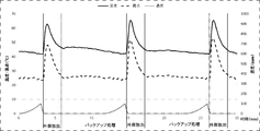
- the concentration of the organic solvent in the treated gas discharged from the organic solvent processing apparatus 1 is low immediately after switching to the adsorption process of the organic solvent processing apparatus 1, and increases as the adsorption process proceeds. Therefore, in the organic solvent recovery system 100, the three-way damper 22 is provided in the first discharge line 17 of the organic solvent processing apparatus 1, and the control gas (not shown) releases the processed gas at the initial stage of the adsorption process from the discharge line 30 to the outside. The three-way damper 22 is controlled so that the treated gas is introduced into the continuous backup device 2 from the introduction line 31 after that. Similarly, also in the organic solvent recovery system 100A, the three-way damper 22 is controlled by a control unit (not shown).
- FIG. 3 shows changes over time in the concentration, dew point, and temperature of the organic solvent in the treated gas discharged from the organic solvent treatment apparatus 1.
- the organic solvent concentration of the treated gas changes periodically as shown in FIG. Therefore, in the organic solvent recovery system 100, a period during which a control unit (not shown) releases the treated gas from the organic solvent processing apparatus 1 by the three-way damper 22 is an initial fixed period of the adsorption process in the organic solvent processing apparatus 1. Control. And after this fixed period, it controls so that processed gas may be introduce
- FIG. Control for a certain period may be performed by setting a timer.
- the initial stage of the adsorption process for releasing the treated gas to the outside is a certain period immediately after switching to the adsorption process.
- “external release” indicates a period during which external discharge is performed
- “backup processing” indicates a period during which the continuous backup apparatus 2 is introduced.
- a gas concentration meter is provided downstream of the first exhaust line of the organic solvent processing apparatus 1, and when a control unit (not shown) reaches the set organic solvent concentration, it is introduced into the continuous backup device 2 from the release of outside air. You may switch to the route you want.
- the initial stage of the adsorption process for releasing the treated gas to the outside is a period from immediately after switching to the adsorption process until reaching the set organic solvent concentration.
- the route may be switched from the outside air release to the continuous backup device 2.
- the initial stage of the adsorption process for releasing the treated gas to the outside is a period from immediately after switching to the adsorption process until it falls below the set dew point.
- the three-way damper 22 may be controlled by appropriately combining any of the above-described controls. As described above, the control unit (not shown) can control the switching of the three-way damper 22 to efficiently improve the purification capability and the recovery efficiency of the organic solvent-containing gas.
- Example 1 In Example 1, the organic solvent recovery system 100 shown in FIG. 1 was used. A gas to be treated having a temperature of 25 ° C. containing 10,000 ppm of methylene chloride was introduced into the treatment tank 13 by the raw gas blower 12 from the treatment gas supply line 11 at an air volume of 5 Nm 3 / min and mounted in the treatment tank 13. Adsorption treatment was performed with 1 adsorbent 14 for 11.5 minutes.
- the first adsorbent 14 an adsorbent in which an activated carbon fiber nonwoven fabric having a specific surface area of 1,000 m 2 / g or more is wound around a metal frame in a cylindrical shape is used.
- the first adsorbent 14 that adsorbed methylene chloride was desorbed for 8 minutes using water vapor. After the desorption process, it was in a standby state until it moved to the next adsorption process (3.5 minutes).
- the desorption gas containing methylene chloride was supplied to the condenser 20 via the desorption steam line 19, and was liquefied and condensed into methylene chloride and water by the condenser 20. Thereafter, the recovered liquid tank 21 was separated into methylene chloride and water.
- the gas to be treated after being adsorbed by the organic solvent treatment apparatus 1 was discharged from the first discharge line 17 as a treated gas and introduced into the three-way damper 22.
- the dew point of the treated gas falls below 27 ° C.
- it is discharged from the three-way damper 22 to the outside air via the discharge line 30, and when the dew point falls below 27 ° C., it continues from the three-way damper 22 via the introduction line 31. Control was performed so as to be introduced into the backup device 2.
- the treated gas discharged from the organic solvent processing apparatus 1 is introduced into the second adsorbent 24 by the treated gas blower 23 to perform the adsorption process, and the second discharge is performed as a cleaning gas.
- the product was discharged from the line 25 to the outside.
- a honeycomb rotor in which 60% or more of activated carbon having a specific surface area of 1,000 m 2 / g or more was used as the second adsorbent 24.
- the concentration of methylene chloride contained in the treated gas discharged from the three-way damper 22 to the exhaust line 30 and the cleaning gas discharged from the continuous backup processing apparatus 2 are reduced.
- the concentration of methylene chloride contained was both 10 ppm or less on average.
- Example 2 the organic solvent recovery system 100A shown in FIG. 2 was used.
- a gas to be treated having a temperature of 25 ° C. containing 10,000 ppm of methylene chloride was introduced into the treatment tank 13 by the raw gas blower 12 from the treatment gas supply line 11 at an air volume of 5 Nm 3 / min and mounted in the treatment tank 13.
- Adsorption treatment was performed with 1 adsorbent 14 for 11.5 minutes.
- the first adsorbent 14 an adsorbent in which an activated carbon fiber nonwoven fabric having a specific surface area of 1,000 m 2 / g or more is wound around a metal frame in a cylindrical shape is used.
- the first adsorbent 14 that adsorbed methylene chloride was desorbed for 8 minutes using water vapor. After the desorption process, it was in a standby state until it moved to the next adsorption process (3.5 minutes).
- the desorption gas containing methylene chloride was supplied to the condenser 20 via the desorption steam line 19, and was liquefied and condensed into methylene chloride and water by the condenser 20. Thereafter, the recovered liquid tank 21 was separated into methylene chloride and water.
- the gas to be treated after being adsorbed by the organic solvent treatment apparatus 1 was discharged from the first discharge line 17 as a treated gas and introduced into the three-way damper 22.
- the dew point of the treated gas falls below 27 ° C.
- it is discharged from the three-way damper 22 to the outside air via the discharge line 30, and when the dew point falls below 27 ° C., the batch is discharged from the three-way damper 22 via the introduction line 31. Control was made so as to be introduced into the backup device 3.
- the treated gas discharged from the organic solvent processing device 1 is introduced into the second adsorbent 24 by the treated gas blower 23 to perform the adsorption treatment, and the second discharge is performed as a cleaning gas.
- the product was discharged from the line 25 to the outside.
- the second adsorbent 24 an adsorbent obtained by wrapping an activated carbon fiber nonwoven fabric having a specific surface area of 1,000 m 2 / g or more in a cylindrical shape around a metal frame was used.
- desorption treatment was performed for 5 minutes using water vapor on the second adsorbent 24 that adsorbed the treated gas.
- the desorption gas containing the treated gas is supplied to the condenser 20 connected to the batch-type backup processing device 3 via the desorption steam line 19 and is liquefied and condensed into methylene chloride and water by the condenser 20. . Thereafter, the recovered liquid tank 21 was separated into methylene chloride and water.
- the non-condensed gas that has not been condensed in the condenser 20 of the batch type backup processing device 3 passes through the return gas line 28 and is a gas to be processed that is upstream of the raw gas blower 12 of the organic solvent processing device 1. Returned to line 11.
- the concentration of methylene chloride contained in the treated gas discharged from the three-way damper 22 to the exhaust line 30 and the cleaning gas discharged from the batch type backup processing device 3 are reduced.
- the concentration of methylene chloride contained was both 10 ppm or less on average.
- Comparative Example 1 In the comparative example 1, the system which closed the exit to the discharge
- a gas to be treated having a temperature of 25 ° C. containing 10,000 ppm of methylene chloride was introduced into the treatment tank 13 by the raw gas blower 12 from the treatment gas supply line 11 at an air volume of 5 Nm 3 / min and mounted in the treatment tank 13.
- Adsorption treatment was performed with 1 adsorbent 14 for 11.5 minutes.
- the 1st adsorption material 14 used the thing similar to Example 1.
- the first adsorbent 14 that adsorbed methylene chloride was desorbed for 8 minutes using water vapor.
- the desorption gas containing methylene chloride was supplied to the condenser 20 via the desorption steam line 19, and was liquefied and condensed into methylene chloride and water by the condenser 20. Thereafter, the recovered liquid tank 21 was separated into methylene chloride and water.
- the gas to be treated after being adsorbed by the organic solvent treatment apparatus 1 was discharged from the first discharge line 17 as a processed gas and introduced into the continuous backup apparatus 2.
- the 2nd adsorption material 24 used the thing similar to Example 1.
- the processed gas is introduced into the second adsorbent 24 by the processed gas blower 23, the adsorption processing is performed by the continuous backup apparatus 2, and the cleaning gas is supplied to the second discharge line 25. Discharged to the outside.
- the outside air flow rate 0.4 Nm 3 / min of the treated gas with the desorption blower 26 is introduced into the heater 27 and heated to 130 ° C., the second The second adsorbent 24 was regenerated by introducing it into the desorption zone of the adsorbent 24. Further, the concentrated gas discharged from the desorption zone of the second adsorbent 24 was returned to the gas supply line 11 via the return gas line 28.
- the concentration of methylene chloride contained in the cleaning gas discharged from the continuous backup treatment apparatus 2 was 30 ppm on average.
- Comparative Example 2 In Comparative Example 2, a system in which the outlet of the three-way damper 22 to the discharge line 30 was closed in the organic solvent recovery system 100A used in Example 2 was used. That is, in the system of Comparative Example 2, the gas to be treated after being adsorbed by the organic solvent treatment apparatus 1 is always introduced into the batch type backup apparatus 3.
- a gas to be treated having a temperature of 25 ° C. containing 10,000 ppm of methylene chloride was introduced into the treatment tank 13 by the raw gas blower 12 from the treatment gas supply line 11 at an air volume of 5 Nm 3 / min and mounted in the treatment tank 13.
- Adsorption treatment was performed with 1 adsorbent 14 for 11.5 minutes.
- the 1st adsorption material 14 used the thing similar to Example 2.
- the first adsorbent 14 that adsorbed methylene chloride was desorbed for 8 minutes using water vapor.
- the desorption gas containing methylene chloride was supplied to the condenser 20 via the desorption steam line 19, and was liquefied and condensed into methylene chloride and water by the condenser 20. Thereafter, the recovered liquid tank 21 was separated into methylene chloride and water.
- the gas to be treated after being subjected to the adsorption treatment by the organic solvent treatment apparatus 1 was discharged from the first discharge line 17 as a processed gas and introduced into the batch type backup apparatus 3 through the introduction line 31.
- the 2nd adsorption material 24 used the thing similar to Example 2.
- the processed gas is introduced into the second adsorbent 24 by the processed gas blower 23, the adsorption processing is performed by the batch type backup apparatus 3, and the cleaning gas is supplied to the second discharge line 25. Discharged to the outside.
- desorption treatment was performed for 5 minutes using water vapor on the second adsorbent 24 that adsorbed the treated gas.
- the desorption gas containing the treated gas is supplied to the condenser 20 connected to the batch-type backup processing device 3 via the desorption steam line 19 and is liquefied and condensed into methylene chloride and water by the condenser 20. . Thereafter, the recovered liquid tank 21 was separated into methylene chloride and water.
- the non-condensed gas that has not been condensed in the condenser 20 of the batch type backup processing device 3 passes through the return gas line 28 and is a gas to be processed that is upstream of the raw gas blower 12 of the organic solvent processing device 1. Returned to line 11.
- the concentration of methylene chloride contained in the cleaning gas discharged from the batch type backup treatment apparatus 3 was 30 ppm on average.
Landscapes
- Chemical & Material Sciences (AREA)
- Engineering & Computer Science (AREA)
- Oil, Petroleum & Natural Gas (AREA)
- Chemical Kinetics & Catalysis (AREA)
- Analytical Chemistry (AREA)
- General Chemical & Material Sciences (AREA)
- Environmental & Geological Engineering (AREA)
- Biomedical Technology (AREA)
- Health & Medical Sciences (AREA)
- Life Sciences & Earth Sciences (AREA)
- Sustainable Development (AREA)
- Treating Waste Gases (AREA)
- Separation Of Gases By Adsorption (AREA)
Abstract
Description
第1吸着材が充填された処理槽を有し、前記処理槽に前記被処理ガスを導入して当該被処理ガスに含まれる有機溶剤を前記第1吸着素材に吸着させ、処理済ガスを排出する第1吸着処理と、前記処理槽に第1脱着用ガスを供給して有機溶剤を前記第1吸着素材から脱着し、濃縮された有機溶剤を含有する第1脱着ガスを排出する第1脱着処理と、を繰り返す有機溶剤処理装置と、
第2吸着材を有し、前記処理済ガスを導入して当該処理済ガスに含まれる有機溶剤を前記第2吸着材に吸着させ、清浄化ガスを排出する第2吸着処理と、前記第2吸着材に第2脱着用ガスを供給して、濃縮された有機溶剤を含有する第2脱着ガスを排出する第2脱着処理と、を行うバックアップ装置と、
前記有機溶剤処理装置と前記バックアップ装置との間に設置され、前記処理済ガスの排出先を切り替える切替部と、
前記処理済ガスを前記第1吸着処理の初期に外部に放出した後に前記処理済ガスを前記バックアップ装置に導入するように、前記切替部を制御する制御部と、を備えたことを特徴とする。
第1吸着材に前記被処理ガスを導入して当該被処理ガスに含まれる有機溶剤を前記第1吸着素材に吸着させ、処理済ガスを排出する第1吸着処理と、前記第1吸着材に第1脱着用ガスを供給して前記第1吸着素材から有機溶剤を脱着し、濃縮された有機溶剤を含有する第1脱着ガスを排出する第1脱着処理と、を繰り返すステップと、
前記処理済ガスを前記第1吸着処理の初期に外部に放出した後に前記処理済ガスを第2吸着材に導入するように、前記処理済ガスの排出先を切り替えるステップと、
前記処理済ガスを導入して当該処理済ガスに含まれる有機溶剤を前記第2吸着材に吸着させ、清浄化ガスを排出する第2吸着処理と、前記第2吸着材に第2脱着用ガスを供給して、濃縮された有機溶剤を含有する第2脱着ガスを排出する第2脱着処理と、を行うステップと、を含むことを特徴とする。
以下に本実施形態の有機溶剤回収システム100,100Aを用いた実施例を示して本発明を具体的に説明するが、本発明は以下の内容に限定されるものではない。
実施例1では、図1に示す有機溶剤回収システム100を用いた。
塩化メチレン10,000ppmを含む温度25℃の被処理ガスを、風量5Nm3/分で被処理ガス供給ライン11から原ガス送風機12にて処理槽13に導入し、処理槽13内に搭載した第1吸着材14にて11.5分間吸着処理を行った。ここで、第1吸着材14には、比表面積が1,000m2/g以上の活性炭素繊維不織布を金枠に円筒状に巻きつけた吸着材を使用した。
塩化メチレン10,000ppmを含む温度25℃の被処理ガスを、風量5Nm3/分で被処理ガス供給ライン11から原ガス送風機12にて処理槽13に導入し、処理槽13内に搭載した第1吸着材14にて11.5分間吸着処理を行った。ここで、第1吸着材14には、比表面積が1,000m2/g以上の活性炭素繊維不織布を金枠に円筒状に巻きつけた吸着材を使用した。
比較例1では、実施例1で用いた有機溶剤回収システム100において、三方ダンパー22の放出ライン30への出口を閉じたシステムを用いた。つまり、この比較例1のシステムでは、有機溶剤処理装置1にて吸着処理された後の被処理ガスが常に連続式バックアップ装置2に導入される。
比較例2では、実施例2で用いた有機溶剤回収システム100Aにおいて、三方ダンパー22の放出ライン30への出口を閉じたシステムを用いた。つまり、この比較例2のシステムでは、有機溶剤処理装置1にて吸着処理された後の被処理ガスが常にバッチ式バックアップ装置3に導入される。
2 連続式バックアップ装置
3 バッチ式バックアップ装置
4 吸脱着処理装置
11 被処理ガス供給ライン
12 原ガス送風機
13 処理槽
14 第1吸着材
17 第1排出ライン
18 水蒸気供給ライン
19 脱着水蒸気ライン
20 凝縮器
21 回収液タンク
22 三方ダンパー(切替部)
23 処理済ガス送風機
24,140 第2吸着材
25 第2排出ライン
26 脱着送風機
27 ヒーター
28 戻りガスライン
30 放出ライン
31 導入ライン
100 有機溶剤回収システム
100A 有機溶剤回収システム
Claims (12)
- 有機溶剤を含有する被処理ガスから当該有機溶剤を除去して清浄化ガスを排出する有機溶剤回収システムであって、
第1吸着材が充填された処理槽を有し、前記処理槽に前記被処理ガスを導入して当該被処理ガスに含まれる有機溶剤を前記第1吸着素材に吸着させ、処理済ガスを排出する第1吸着処理と、前記処理槽に第1脱着用ガスを供給して有機溶剤を前記第1吸着素材から脱着し、濃縮された有機溶剤を含有する第1脱着ガスを排出する第1脱着処理と、を繰り返す有機溶剤処理装置と、
第2吸着材を有し、前記処理済ガスを導入して当該処理済ガスに含まれる有機溶剤を前記第2吸着材に吸着させ、清浄化ガスを排出する第2吸着処理と、前記第2吸着材に第2脱着用ガスを供給して、濃縮された有機溶剤を含有する第2脱着ガスを排出する第2脱着処理と、を行うバックアップ装置と、
前記有機溶剤処理装置と前記バックアップ装置との間に設置され、前記処理済ガスの排出先を切り替える切替部と、
前記処理済ガスを前記第1吸着処理の初期に外部に放出した後に前記処理済ガスを前記バックアップ装置に導入するように、前記切替部を制御する制御部と、
を備えたことを特徴とする有機溶剤回収システム。 - 前記制御部は、タイマー制御により、前記第1吸着処理の初期の一定期間に外部に放出し、一定期間後に前記処理済ガスを前記バックアップ装置に導入するように前記切替部を制御することを特徴とする請求項1に記載の有機溶剤回収システム。
- 前記有機溶剤処理装置から排出された前記処理済ガスの濃度を測定するガス濃度計を備え、
前記制御部は、前記ガス濃度計による測定値が所定値を上回ると、前記処理済ガスを外部に放出する状態から前記バックアップ装置に導入する状態に前記切替部を制御することを特徴とする請求項1に記載の有機溶剤回収システム。 - 前記有機溶剤処理装置から排出された前記処理済ガスの露点を測定する露点計を備え、
前記制御部は、前記露点計による測定値が所定値を下回ると、前記処理済ガスを外部に放出する状態から前記バックアップ装置に導入する状態に前記切替部を制御することを特徴とする請求項1に記載の有機溶剤回収システム。 - 前記第2吸着材は筒状に設けられ、
前記バックアップ装置は、前記第2吸着材をその筒軸周りに回転することで、前記第2吸着処理に用いる吸着領域と前記第2脱着処理に用いる脱着領域とを切り替えることを特徴とする請求項1~4のいずれか1項に記載の有機溶剤回収システム。 - 前記バックアップ装置は、
前記第2吸着材が充填された処理槽を有し、前記第2吸着処理と前記第2脱着処理を交互に行う吸脱着処理装置と、
前記第2脱着ガスから有機溶剤を液化回収する凝縮器と、を備えたことを特徴とする請求項1~4のいずれか1項に記載の有機溶剤回収システム。 - 前記バックアップ装置から排出された前記第2脱着ガスを前記被処理ガスに混入させるラインを備えていることを特徴とする請求項1~5に記載の有機溶剤回収システム。
- 前記凝縮器での未濃縮の前記第2脱着ガスを、前記被処理ガスに混入させるラインを備えていることを特徴とする請求項6に記載の有機溶剤回収システム。
- 前記切替部は、ダンパーにより構成されていることを特徴とする請求項1~8のいずれか1項に記載の有機溶剤回収システム。
- 前記第1吸着材は活性炭素繊維または粒状活性炭の少なくとも一つを含むことを特徴とする請求項1~9のいずれか1項に記載の有機溶剤回収システム。
- 前記第2吸着材は活性炭、ゼオライトまたはシリカゲルの少なくとも一つを含むことを特徴とする請求項1~10のいずれか1項に記載の有機溶剤回収システム。
- 有機溶剤を含有する被処理ガスから当該有機溶剤を除去して清浄化ガスを排出する有機溶剤回収方法であって、
第1吸着材に前記被処理ガスを導入して当該被処理ガスに含まれる有機溶剤を前記第1吸着素材に吸着させ、処理済ガスを排出する第1吸着処理と、前記第1吸着材に第1脱着用ガスを供給して前記第1吸着素材から有機溶剤を脱着し、濃縮された有機溶剤を含有する第1脱着ガスを排出する第1脱着処理と、を繰り返すステップと、
前記処理済ガスを前記第1吸着処理の初期に外部に放出した後に前記処理済ガスを第2吸着材に導入するように、前記処理済ガスの排出先を切り替えるステップと、
前記処理済ガスを導入して当該処理済ガスに含まれる有機溶剤を前記第2吸着材に吸着させ、清浄化ガスを排出する第2吸着処理と、前記第2吸着材に第2脱着用ガスを供給して、濃縮された有機溶剤を含有する第2脱着ガスを排出する第2脱着処理と、を行うステップと、
を含むことを特徴とする有機溶剤回収方法。
Priority Applications (3)
| Application Number | Priority Date | Filing Date | Title |
|---|---|---|---|
| CN201780074301.0A CN110035816A (zh) | 2016-12-01 | 2017-11-28 | 有机溶剂回收系统及有机溶剂回收方法 |
| JP2018554156A JP7103226B2 (ja) | 2016-12-01 | 2017-11-28 | 有機溶剤回収システム及び有機溶剤回収方法 |
| KR1020197015394A KR20190084067A (ko) | 2016-12-01 | 2017-11-28 | 유기 용제 회수 시스템 및 유기 용제 회수 방법 |
Applications Claiming Priority (2)
| Application Number | Priority Date | Filing Date | Title |
|---|---|---|---|
| JP2016-233959 | 2016-12-01 | ||
| JP2016233959 | 2016-12-01 |
Publications (1)
| Publication Number | Publication Date |
|---|---|
| WO2018101255A1 true WO2018101255A1 (ja) | 2018-06-07 |
Family
ID=62242220
Family Applications (1)
| Application Number | Title | Priority Date | Filing Date |
|---|---|---|---|
| PCT/JP2017/042607 Ceased WO2018101255A1 (ja) | 2016-12-01 | 2017-11-28 | 有機溶剤回収システム及び有機溶剤回収方法 |
Country Status (4)
| Country | Link |
|---|---|
| JP (1) | JP7103226B2 (ja) |
| KR (1) | KR20190084067A (ja) |
| CN (1) | CN110035816A (ja) |
| WO (1) | WO2018101255A1 (ja) |
Cited By (9)
| Publication number | Priority date | Publication date | Assignee | Title |
|---|---|---|---|---|
| CN109731440A (zh) * | 2019-03-12 | 2019-05-10 | 上海锅炉厂有限公司 | 一种同心双筒吸附处理装置 |
| JPWO2020158442A1 (ja) * | 2019-01-31 | 2020-08-06 | ||
| JPWO2022014013A1 (ja) * | 2020-07-16 | 2022-01-20 | ||
| JPWO2022014012A1 (ja) * | 2020-07-16 | 2022-01-20 | ||
| JPWO2022054733A1 (ja) * | 2020-09-11 | 2022-03-17 | ||
| CN115722033A (zh) * | 2021-08-31 | 2023-03-03 | 华懋科技股份有限公司 | 具洗涤吸收塔的中空纤维管式膜油气处理系统及其方法 |
| WO2024070943A1 (ja) * | 2022-09-30 | 2024-04-04 | 東洋紡エムシー株式会社 | 有機溶剤回収システム |
| WO2024128082A1 (ja) * | 2022-12-14 | 2024-06-20 | 東洋紡エムシー株式会社 | 有機溶剤回収システム、および有機溶剤処理システム |
| WO2024203539A1 (ja) * | 2023-03-24 | 2024-10-03 | 東洋紡エムシー株式会社 | 有機溶剤回収システム |
Families Citing this family (2)
| Publication number | Priority date | Publication date | Assignee | Title |
|---|---|---|---|---|
| TW202131987A (zh) * | 2019-12-25 | 2021-09-01 | 日商東洋紡股份有限公司 | 有機溶劑回收系統 |
| KR102362907B1 (ko) * | 2020-12-08 | 2022-02-14 | 송철환 | 유기 용제를 함유하는 배기 가스로부터 유기 용제를 회수하는 유기 용제 회수 시스템 및 유기 용제 회수 방법 |
Citations (6)
| Publication number | Priority date | Publication date | Assignee | Title |
|---|---|---|---|---|
| JPH10286426A (ja) * | 1997-04-15 | 1998-10-27 | Kuraray Eng Kk | 連続式吸着装置とその使用方法 |
| JP2007105657A (ja) * | 2005-10-14 | 2007-04-26 | Matsushita Electric Ind Co Ltd | ガス処理装置 |
| JP2010203639A (ja) * | 2009-03-02 | 2010-09-16 | Matsui Mfg Co | 粉粒体材料の除湿乾燥装置、及び粉粒体材料の除湿乾燥方法 |
| JP2012183462A (ja) * | 2011-03-04 | 2012-09-27 | Toho Kako Kensetsu Kk | 有機溶剤の除去方法及び除去装置 |
| JP2014147863A (ja) * | 2013-01-31 | 2014-08-21 | Toyobo Co Ltd | ガス処理装置およびガス処理方法 |
| JP2015000381A (ja) * | 2013-06-17 | 2015-01-05 | 東洋紡株式会社 | 有機溶剤回収システム |
Family Cites Families (13)
| Publication number | Priority date | Publication date | Assignee | Title |
|---|---|---|---|---|
| JPS5445405Y2 (ja) | 1974-09-30 | 1979-12-26 | ||
| JPS60168515A (ja) * | 1984-02-10 | 1985-09-02 | Toyobo Co Ltd | 混合溶剤分離回収装置 |
| JPS6411326A (en) | 1987-07-06 | 1989-01-13 | Toshiba Corp | Projection aligner |
| JP3492018B2 (ja) * | 1995-05-10 | 2004-02-03 | 三菱重工業株式会社 | 揮発性有機物の回収方法 |
| JP3841479B2 (ja) | 1996-05-20 | 2006-11-01 | 東邦化工建設株式会社 | 有機溶剤回収システム及び有機溶剤回収方法 |
| JP2001179041A (ja) | 1999-12-27 | 2001-07-03 | Toyobo Co Ltd | ガス処理装置 |
| CN1261190C (zh) * | 2003-03-18 | 2006-06-28 | 力晶半导体股份有限公司 | 废气排放处理系统 |
| JP2007253136A (ja) | 2006-03-27 | 2007-10-04 | Matsushita Electric Ind Co Ltd | 有機溶剤回収装置 |
| JP2008000660A (ja) | 2006-06-21 | 2008-01-10 | Matsushita Electric Ind Co Ltd | 有機溶剤濃縮装置 |
| TW200938292A (en) * | 2009-05-27 | 2009-09-16 | Jg Environmental Tech Co Ltd | Re-purification device and method for volatile organic substance |
| CN101915687B (zh) * | 2010-08-04 | 2012-03-28 | 聚光科技(杭州)股份有限公司 | 一种应用在分析仪器中的气体预处理方法及装置 |
| JP2014147864A (ja) * | 2013-01-31 | 2014-08-21 | Toyobo Co Ltd | ガス処理装置およびガス処理方法 |
| CN103990351B (zh) * | 2014-05-31 | 2016-05-25 | 蔡博 | 一种挥发性有机废气的净化回收装置 |
-
2017
- 2017-11-28 WO PCT/JP2017/042607 patent/WO2018101255A1/ja not_active Ceased
- 2017-11-28 KR KR1020197015394A patent/KR20190084067A/ko not_active Ceased
- 2017-11-28 CN CN201780074301.0A patent/CN110035816A/zh active Pending
- 2017-11-28 JP JP2018554156A patent/JP7103226B2/ja active Active
Patent Citations (6)
| Publication number | Priority date | Publication date | Assignee | Title |
|---|---|---|---|---|
| JPH10286426A (ja) * | 1997-04-15 | 1998-10-27 | Kuraray Eng Kk | 連続式吸着装置とその使用方法 |
| JP2007105657A (ja) * | 2005-10-14 | 2007-04-26 | Matsushita Electric Ind Co Ltd | ガス処理装置 |
| JP2010203639A (ja) * | 2009-03-02 | 2010-09-16 | Matsui Mfg Co | 粉粒体材料の除湿乾燥装置、及び粉粒体材料の除湿乾燥方法 |
| JP2012183462A (ja) * | 2011-03-04 | 2012-09-27 | Toho Kako Kensetsu Kk | 有機溶剤の除去方法及び除去装置 |
| JP2014147863A (ja) * | 2013-01-31 | 2014-08-21 | Toyobo Co Ltd | ガス処理装置およびガス処理方法 |
| JP2015000381A (ja) * | 2013-06-17 | 2015-01-05 | 東洋紡株式会社 | 有機溶剤回収システム |
Cited By (24)
| Publication number | Priority date | Publication date | Assignee | Title |
|---|---|---|---|---|
| JPWO2020158442A1 (ja) * | 2019-01-31 | 2020-08-06 | ||
| WO2020158442A1 (ja) * | 2019-01-31 | 2020-08-06 | 東洋紡株式会社 | 有機溶剤回収システム |
| CN113365718A (zh) * | 2019-01-31 | 2021-09-07 | 东洋纺株式会社 | 有机溶剂回收系统 |
| JP7380571B2 (ja) | 2019-01-31 | 2023-11-15 | 東洋紡エムシー株式会社 | 有機溶剤回収システム |
| CN113365718B (zh) * | 2019-01-31 | 2023-07-25 | 东洋纺株式会社 | 有机溶剂回收系统 |
| CN109731440A (zh) * | 2019-03-12 | 2019-05-10 | 上海锅炉厂有限公司 | 一种同心双筒吸附处理装置 |
| WO2022014012A1 (ja) * | 2020-07-16 | 2022-01-20 | 東洋紡株式会社 | 有機溶剤回収システム |
| TWI851909B (zh) * | 2020-07-16 | 2024-08-11 | 日商東洋紡Mc股份有限公司 | 有機溶劑回收系統 |
| JP7544039B2 (ja) | 2020-07-16 | 2024-09-03 | 東洋紡エムシー株式会社 | 有機溶剤回収システム |
| WO2022014013A1 (ja) * | 2020-07-16 | 2022-01-20 | 東洋紡株式会社 | 有機溶剤回収システム |
| EP4183471A4 (en) * | 2020-07-16 | 2024-04-24 | TOYOBO MC Corporation | ORGANIC SOLVENTS RECOVERY SYSTEM |
| CN116133734A (zh) * | 2020-07-16 | 2023-05-16 | 东洋纺株式会社 | 有机溶剂回收系统 |
| JPWO2022014012A1 (ja) * | 2020-07-16 | 2022-01-20 | ||
| JPWO2022014013A1 (ja) * | 2020-07-16 | 2022-01-20 | ||
| JP7428184B2 (ja) | 2020-07-16 | 2024-02-06 | 東洋紡エムシー株式会社 | 有機溶剤回収システム |
| EP4183470A4 (en) * | 2020-07-16 | 2024-04-24 | TOYOBO MC Corporation | Organic solvent recovery system |
| WO2022054733A1 (ja) * | 2020-09-11 | 2022-03-17 | 東洋紡株式会社 | 有機溶剤回収システム |
| JPWO2022054733A1 (ja) * | 2020-09-11 | 2022-03-17 | ||
| JP7729335B2 (ja) | 2020-09-11 | 2025-08-26 | 東洋紡エムシー株式会社 | 有機溶剤回収システム |
| CN115722033A (zh) * | 2021-08-31 | 2023-03-03 | 华懋科技股份有限公司 | 具洗涤吸收塔的中空纤维管式膜油气处理系统及其方法 |
| WO2024070943A1 (ja) * | 2022-09-30 | 2024-04-04 | 東洋紡エムシー株式会社 | 有機溶剤回収システム |
| WO2024128082A1 (ja) * | 2022-12-14 | 2024-06-20 | 東洋紡エムシー株式会社 | 有機溶剤回収システム、および有機溶剤処理システム |
| JP7544308B1 (ja) * | 2022-12-14 | 2024-09-03 | 東洋紡エムシー株式会社 | 有機溶剤回収システム、および有機溶剤処理システム |
| WO2024203539A1 (ja) * | 2023-03-24 | 2024-10-03 | 東洋紡エムシー株式会社 | 有機溶剤回収システム |
Also Published As
| Publication number | Publication date |
|---|---|
| JP7103226B2 (ja) | 2022-07-20 |
| KR20190084067A (ko) | 2019-07-15 |
| CN110035816A (zh) | 2019-07-19 |
| JPWO2018101255A1 (ja) | 2019-10-24 |
Similar Documents
| Publication | Publication Date | Title |
|---|---|---|
| JP7103226B2 (ja) | 有機溶剤回収システム及び有機溶剤回収方法 | |
| JP6897884B2 (ja) | 有機溶剤回収システム | |
| JP5689733B2 (ja) | 吸着操作からのnf3の回収 | |
| JP5482776B2 (ja) | 有機溶剤含有ガス処理システム | |
| JP6236898B2 (ja) | 有機溶剤含有ガス処理システム | |
| JPH09308814A (ja) | 有機溶剤回収システム及び有機溶剤回収方法 | |
| US10427090B2 (en) | Control of swing adsorption process cycle time with ambient CO2 monitoring | |
| JP2015000381A (ja) | 有機溶剤回収システム | |
| JP5029590B2 (ja) | 排水処理システム | |
| JP2014117638A (ja) | 有機溶剤含有ガス処理システム | |
| JP5862278B2 (ja) | 有機溶剤含有ガス処理システム | |
| JP2010142728A (ja) | 排ガス処理システム | |
| JP4548891B2 (ja) | 有機溶剤の回収方法 | |
| JP2010142790A (ja) | 排ガス処理システム | |
| JP7494838B2 (ja) | 有機溶剤回収システム | |
| JP5856992B2 (ja) | ガス製造方法 | |
| JP5978808B2 (ja) | 排水処理システム | |
| JPH0938445A (ja) | 吸着塔の再生方法 | |
| JP3183381B2 (ja) | 高濃度有機溶剤含有少風量ガスからの有機溶剤回収方法 | |
| WO2024203899A1 (ja) | 有機溶剤回収システム及び有機溶剤回収方法 | |
| JP2971127B2 (ja) | ドライクリーニング方法 | |
| JP6772470B2 (ja) | 有機溶剤処理装置 | |
| JPWO2000062921A1 (ja) | ガス状化学物質吸着体およびそれを用いた吸着除去装置 | |
| JPH02261516A (ja) | 加熱空気再生式溶剤回収装置 |
Legal Events
| Date | Code | Title | Description |
|---|---|---|---|
| 121 | Ep: the epo has been informed by wipo that ep was designated in this application |
Ref document number: 17876045 Country of ref document: EP Kind code of ref document: A1 |
|
| ENP | Entry into the national phase |
Ref document number: 2018554156 Country of ref document: JP Kind code of ref document: A |
|
| ENP | Entry into the national phase |
Ref document number: 20197015394 Country of ref document: KR Kind code of ref document: A |
|
| NENP | Non-entry into the national phase |
Ref country code: DE |
|
| 122 | Ep: pct application non-entry in european phase |
Ref document number: 17876045 Country of ref document: EP Kind code of ref document: A1 |