WO2018097328A1 - 車両の制動制御装置 - Google Patents
車両の制動制御装置 Download PDFInfo
- Publication number
- WO2018097328A1 WO2018097328A1 PCT/JP2017/042687 JP2017042687W WO2018097328A1 WO 2018097328 A1 WO2018097328 A1 WO 2018097328A1 JP 2017042687 W JP2017042687 W JP 2017042687W WO 2018097328 A1 WO2018097328 A1 WO 2018097328A1
- Authority
- WO
- WIPO (PCT)
- Prior art keywords
- braking
- vehicle
- wheel
- pressure
- value
- Prior art date
- Legal status (The legal status is an assumption and is not a legal conclusion. Google has not performed a legal analysis and makes no representation as to the accuracy of the status listed.)
- Ceased
Links
Images



Classifications
-
- B—PERFORMING OPERATIONS; TRANSPORTING
- B60—VEHICLES IN GENERAL
- B60T—VEHICLE BRAKE CONTROL SYSTEMS OR PARTS THEREOF; BRAKE CONTROL SYSTEMS OR PARTS THEREOF, IN GENERAL; ARRANGEMENT OF BRAKING ELEMENTS ON VEHICLES IN GENERAL; PORTABLE DEVICES FOR PREVENTING UNWANTED MOVEMENT OF VEHICLES; VEHICLE MODIFICATIONS TO FACILITATE COOLING OF BRAKES
- B60T17/00—Component parts, details, or accessories of power brake systems not covered by groups B60T8/00, B60T13/00 or B60T15/00, or presenting other characteristic features
- B60T17/18—Safety devices; Monitoring
- B60T17/22—Devices for monitoring or checking brake systems; Signal devices
Definitions
- the present invention relates to a vehicle braking control device.
- Patent Document 1 describes “related to improvement of antilock control when one system of a two-system hydraulic brake device fails”. As for the method of estimating the failure, in anti-skid control, “other than that the hydraulic pressure control is not started in the other system even after a certain time has elapsed after the hydraulic pressure control is started in either of the two systems. It is estimated that the strain of the
- Patent Document 2 states that in a brake hydraulic pressure control device that performs brake hydraulic pressure control for each wheel of a vehicle via two hydraulic systems, any hydraulic pressure can be easily and reliably used without using a hydraulic pressure sensor.
- a brake fluid pressure control device capable of detecting a system failure state and appropriately performing braking force control according to the detection result is described. For a specific determination method, “When hydraulic speed control based on anti-skid control, the wheel speed on the wheel side to be controlled should be equal to or lower than the wheel speed on the wheel side that is not to be controlled, the former is larger. Since the one-system anti-skid control is not performed, it is determined that the state is a failure state when this state continues for a predetermined time or more.
- Patent Documents 1 and 2 the failure state of the braking system is determined on the assumption that anti-skid control is executed.
- the situation where anti-skid control is executed during normal braking is very rare, and the frequency of failure determination is limited. For this reason, a braking control device that can determine whether or not a braking system has failed in general traveling of a vehicle is desired.
- the vehicle braking control apparatus includes a wheel cylinder (WCfl) for a left front wheel (WHfl) and a wheel cylinder for a right rear wheel (WHrr) from a first chamber (Rm1) of a pressure unit (KAU) of the vehicle.
- WCfl wheel cylinder
- WHfl left front wheel
- WHrr wheel cylinder
- Rm1 first chamber
- KAU pressure unit
- the pressure adjusting unit (CAU) for individually adjusting the hydraulic pressure (Pwrl) of the wheel cylinder (WCrl), and the turning state sensors (YRA, GYA) for obtaining detected values (Yra, Gya) of the turning state of the vehicle.
- the pressure adjusting unit (CAU) calculates an actual value (Yrj, Gyj, Swj) based on the detected value (Yra, Gya) of the turning state during braking of the vehicle.
- a reference value (Yrt, Gyt, Swa) corresponding to the actual value (Yrj, Gyj, Swj) is determined based on the steering angle (Swa), and the actual value (Yrj, Gyj, Swj) and the A deviation (eYr, eGy, eSw) from a reference value (Yrt, Gyt, Swa) is calculated, and based on the deviation (eYr, eGy, eSw), “the first braking system (SK1) and the first A failure determination (S170) is performed to determine whether or not any one of the two braking systems (SK2) is in a failure state.
- the pressure adjustment unit determines that the failure state is present when the deviation (eYr, eGy, eSw) is greater than or equal to a predetermined difference (eyx), and the deviation (eYr, eGy, eSw) Is less than a predetermined difference (eyx), it is determined that the failure state is not present.
- the failure determination can be performed during normal braking, the failure state can be detected with high frequency and reliability. Further, since the detection values Yra and Gya of the turning state are not affected by the deceleration slip Sgn, a highly accurate determination can be performed.
- the vehicle braking control apparatus includes an operation amount sensor (BPA, PMC) for detecting an operation amount (Bpa, Pmc) of the braking operation member (BP) of the vehicle, and the pressure adjusting unit (CAU). Determines whether or not the actual value (Yrj, Gyj, Swj) is increasing with respect to the increase in the operation amount (Bpa, Pmc).
- BPA, PMC operation amount sensor
- CAU pressure adjusting unit
- the deviation (eYr, eGy, eSw) is greater than or equal to a predetermined difference (eyx)” and “the actual value (Yrj, Gyj, Swj) with respect to the increase in the operation amount (Bpa, Pmc)” If at least one of “increase in” is denied, it is determined that the failure state is not present.
- the yaw moment acting on the vehicle increases as the braking operation amount Bpa (for example, the operation displacement of the braking operation member BP, the master cylinder hydraulic pressure Pmc) increases.
- the braking operation amount Bpa for example, the operation displacement of the braking operation member BP, the master cylinder hydraulic pressure Pmc
- a condition based on the mutual relationship between the operation amount Bpa and the actual value (Yrj or the like) is added to the determination based on the yaw rate deviation eYr. Since two conditions are adopted for the determination of the failure state, the determination reliability can be improved.
- the pressure adjustment unit (CAU) permits the execution of the failure determination (S170) when the steering angle (Swa) is less than a predetermined steering angle (swx), When the steering angle (Swa) is greater than or equal to a predetermined steering angle (swx), the execution of the failure determination (S170) is prohibited.
- the situation can be appropriately avoided by the suitability determination based on the steering angle Swa.
- the failure determination can be executed only when the vehicle is traveling substantially straight.
- the vehicle braking control apparatus includes a wheel speed sensor (VWA **) that detects a speed (Vwa **) of a wheel of the vehicle, and the pressure adjustment unit (CAU) Anti-skid control that suppresses excessive slip of the wheel (WH **) is executed based on Vwa **).
- VWA ** wheel speed sensor
- CAU pressure adjustment unit
- Anti-skid control that suppresses excessive slip of the wheel (WH **) is executed based on Vwa **).
- FLab 0
- the magnitudes of the deviations eYr, eGy, eSw may increase due to the left / right difference of the braking force.
- the suitability determination based on the execution status of the anti-skid control is adopted, and the status can be appropriately avoided.
- the failure determination can be executed only during normal braking when the anti-skid control is not executed.
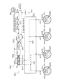
- FIG. 1 is an overall configuration diagram for explaining a first embodiment of a vehicle braking control device BCS according to the present invention
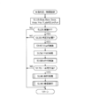
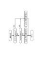
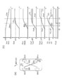
- FIG. It is a flowchart for demonstrating the one-system failure determination and the process of failure compensation control. It is a flowchart for demonstrating the necessity determination process about one system failure determination. It is a whole block diagram for demonstrating 2nd Embodiment of the braking control apparatus BCS of the vehicle which concerns on this invention. It is a time series diagram etc. for demonstrating an effect
- 1 is an overall configuration diagram for explaining an embodiment of a vehicle braking control device BCS according to the present invention.
- FIG. It is a flowchart for demonstrating the process of failure control. It is the schematic for demonstrating a subject, an effect
- “Subscript“ ** ”added to the end of various symbols and the like is a comprehensive symbol indicating whether the vehicle is related to any of the four front, rear, left and right wheels.
- the subscript “**” may be omitted.
- Each subscript corresponds to “fl” for the left front wheel, “fr” for the right front wheel, “rl” for the left rear wheel, and “rr” for the right rear wheel, respectively.
- the wheel speed sensor VWA ** includes a wheel speed sensor VWAfl for the left front wheel, a wheel speed sensor VWAfr for the right front wheel, a wheel speed sensor VWArl for the left rear wheel, and a wheel speed sensor VWArr for the right rear wheel. Shown in When the subscript “**” is omitted, it is simply written as “VWA”.
- the braking control device BCS employs a diagonal type two-system braking system.
- the braking system related to the left front wheel WHfl and the right rear wheel WHrr is “first braking system SK1”
- the braking system related to the right front wheel WHfr and the left rear wheel WHrl is “second braking system SK2”. It is.
- “HP1” represents a fluid pump related to the first braking system SK1
- “HP2” represents a fluid pump related to the second braking system SK2.
- a first embodiment of a vehicle braking control device BCS according to the present invention will be described with reference to the overall configuration diagram of FIG.
- a vehicle including the braking control device BCS includes a braking operation member BP, a braking operation amount sensor BPA, a braking switch BSW, a steering operation member SW, a steering angle sensor SWA, a yaw rate sensor YRA, a longitudinal acceleration sensor GXA, a lateral acceleration sensor GYA, A pressure unit KAU, a pressure adjustment unit CAU, and an indicator IND are provided.
- each wheel WH ** of the vehicle is provided with a brake caliper CP **, a wheel cylinder WC **, a rotating member KT **, a friction member MS **, and a wheel speed sensor VWA **.
- pressurization unit KAU and pressure regulation unit CAU are fluidly connected via the 1st and 2nd pressurization piping HK1 and HK2.
- the pressure adjusting unit CAU and the wheel cylinder WC ** are fluidly connected via a pressure adjusting pipe HC ** corresponding to each wheel WH **.
- Brake operation member (for example, brake pedal) BP is a member that the driver operates to decelerate the vehicle.
- the braking torque for the wheel WH ** is adjusted, and a braking force is generated on the wheel WH.
- a rotating member for example, a brake disc
- a brake caliper CP ** is arranged so as to sandwich the rotating member KT **.
- a brake caliper (also simply referred to as a caliper) CP ** is provided with a wheel cylinder WC **.
- the piston in the wheel cylinder WC moves (forwards or reverses) with respect to the rotating member KT. Is done.
- a friction member for example, a brake pad
- MS ** (not shown) is pressed against the rotating member KT **, and a pressing force is generated.
- the rotating member KT ** and the wheel WH ** are fixed so as to rotate together. For this reason, braking torque is applied to the wheel WH ** by the frictional force between the friction member MS ** and the rotation member KT ** generated by the pressing force. As a result, braking force is generated on the wheels WH **, and the vehicle decelerates.
- the braking operation member BP is provided with a braking operation amount sensor (also simply referred to as “operation amount sensor”) BPA.
- An operation amount Bpa of the braking operation member (brake pedal) BP by the driver is detected by the operation amount sensor BPA.
- the brake operation amount sensor BPA the hydraulic pressure sensor PMC that detects the pressure Pmc of the master cylinder MC, the operation displacement sensor that detects the operation displacement of the brake operation member BP, and the operation force of the brake operation member BP are used. At least one of operating force sensors to be detected is employed.
- the operation amount sensor BPA is a general term for the master cylinder hydraulic pressure sensor PMC, the operation displacement sensor, and the operation force sensor. Accordingly, the brake operation amount Bpa is determined based on at least one of the hydraulic pressure Pmc of the master cylinder MC, the operation displacement of the brake operation member BP, and the operation force of the brake operation member BP.
- the manipulated variable detection value Bpa is input to the controller ECU.
- the brake operation member BP is provided with a brake switch BSW.
- the brake switch BSW is an ON / OFF switch, and detects whether or not the brake operation member BP is operated.
- the signal Bsw detected by the brake switch BSW is input to the controller ECU. Specifically, as the switch signal Bsw, an ON signal is detected when the braking operation member BP is operated, and an OFF signal is detected when the braking operation member BP is not operated.
- Steering operation member (for example, steering wheel) SW is a member operated by the driver to turn the vehicle.
- the steering angle of the steering wheel for example, front wheels WHfl, WHfr
- a lateral force turning force
- the steering operation member SW is provided with a steering angle sensor SWA.
- the steering angle sensor SWA detects the operation amount (steering angle) Swa of the steering operation member (steering wheel) SW by the driver. Further, since the relationship between the steering operation member SW and the steering wheel (that is, the steering gear ratio Ns) is known, the angle of the steering wheel (for example, the front wheels WHfl, WHfr) can be adopted as the steering angle Swa.
- the neutral position of the steering operation member SW corresponds to “0”.
- the steering angle Swa corresponds to a positive sign (plus) value when the vehicle corresponds to a left turn of the vehicle with respect to the neutral position (when the steering operation member SW is operated counterclockwise), and corresponds to a right turn of the vehicle. In this case (when the steering operation member SW is operated clockwise), a negative sign (minus) value is set.
- the detected steering angle detection value Swa is input to the controller ECU.
- the vehicle is equipped with a yaw rate sensor YRA.
- the actual yaw rate Yra of the vehicle is detected by the yaw rate sensor YRA.
- the detection value Yra of the yaw rate is a positive sign (plus) value when the vehicle is in a left turn state (counterclockwise direction when viewed from above the vehicle), and is a clock value when viewed from the top of the vehicle. It is set to take a negative sign (minus) value in the case of the rotation direction.
- the detected yaw rate detection value Yra is input to the controller ECU.
- the vehicle is provided with a longitudinal acceleration sensor GXA.
- the actual longitudinal acceleration Gxa of the vehicle is detected by the longitudinal acceleration sensor GXA.
- the longitudinal acceleration detection value Gxa is set to take a positive sign (plus) value when the vehicle (moving forward) is in an acceleration state and a negative sign (minus) value when the vehicle is in a deceleration state. Has been.
- the detected longitudinal acceleration detection value Gxa is input to the controller ECU.
- the vehicle is provided with a lateral acceleration sensor GYA.
- the actual lateral acceleration Gya of the vehicle is detected by the lateral acceleration sensor GYA.
- the detected value Gya of the lateral acceleration is a positive sign (plus) value when the vehicle is in a left turn state (counterclockwise direction when viewed from above the vehicle), and is a right turn state (when viewed from above the vehicle). It is set to take a negative sign (minus) value when it is in the clockwise direction.
- the detected lateral acceleration detection value Gya is input to the controller ECU.
- the vehicle wheel WH ** is equipped with a wheel speed sensor VWA **.
- a rotational speed (wheel speed) Vwa ** of each wheel WH ** is detected by the wheel speed sensor VWA **.
- an electromagnetic pickup type sensor can be adopted as the wheel speed sensor VWA **.
- the detected value Vwa ** of the wheel speed is input to the controller ECU.
- the pressure unit KAU will be described.
- a braking fluid pressure corresponding to the operating force of the braking operation member BP is generated by the pressurizing unit KAU, and toward the wheel cylinders WC ** disposed on the respective wheels WH ** via the pressure adjusting unit CAU, The brake fluid is pumped.
- the pressurizing unit KAU includes a brake booster BB, a tandem master cylinder MC, and a master reservoir RVM.
- the brake booster (simply referred to as “booster”) BB responds to the operation of the braking operation member BP, assists the operation force of the braking operation member BP at a predetermined rate, and transmits the assisted operation force to the master cylinder MC.
- the negative pressure in the intake pipe of the engine is used for the booster BB. That is, a negative pressure booster is employed as the booster BB.
- the booster BB one that utilizes the hydraulic pressure accumulated in the accumulator (hydraulic booster) or one that is directly driven by an electric motor (electric booster) can be adopted.
- the tandem master cylinder (simply referred to as “master cylinder”) MC converts the operation force of the brake operation member BP into a hydraulic pressure and pumps the brake fluid (brake fluid) to the wheel cylinder WC ** of each wheel WH **.
- master cylinder converts the operation force of the brake operation member BP into a hydraulic pressure and pumps the brake fluid (brake fluid) to the wheel cylinder WC ** of each wheel WH **.
- the interior of the master cylinder MC is partitioned by the inner wall of the master cylinder MC and the two first and second pistons PSM, PSN, and two hydraulic chambers (first and second chambers Rm1, Rm2). Is formed.
- the first chamber Rm1 has a first port
- the second chamber Rm2 has a second port.
- the master cylinder MC receives supply of the brake fluid from the master reservoir RVM, and pumps the brake fluid from the two ports at a fluid pressure Pmc corresponding to the assisted operation force. Note that the hydraulic pressures in the first chamber Rm1 and the second chamber Rm2 are substantially the same.
- the first port of the first chamber Rm1 and the second port of the second chamber Rm2 are connected to each wheel cylinder WC ** and fluid passages (pressurization piping, pressure regulation piping) HK1, HK2, via the modulator HMJ. Connected by HC **.
- the first chamber Rm1 of the master cylinder MC is fluidly connected to the wheel cylinder WCfl of the left front wheel WHfl and the wheel cylinder WCrr of the right rear wheel WHrr.
- the piston PSM moves forward (moves leftward in the figure), and the volume of the first chamber Rm1 is reduced. Accordingly, the brake fluid in the first chamber Rm1 is pumped from the first chamber Rm1 toward the left front wheel wheel cylinder WCfl and the right rear wheel wheel cylinder WCrr.
- the second chamber Rm2 of the master cylinder MC is fluidly connected to the wheel cylinder WCfr of the right front wheel WHfr and the wheel cylinder WCrl of the left rear wheel WHrl.
- the piston PSN moves forward (moves leftward in the figure), and the volume of the second chamber Rm2 is reduced. Accordingly, the brake fluid in the second chamber Rm2 is pumped from the second chamber Rm2 toward the right front wheel wheel cylinder WCfr and the left rear wheel wheel cylinder WCrl.
- the path (fluid path) through which the brake fluid is moved between the master cylinder MC and the four wheel cylinders WC ** is composed of two braking systems.
- first braking system SK1 the system from the first chamber Rm1 to the wheel cylinders WCfl and WCrr
- second braking system SK2 A system from the second chamber Rm2 to the wheel cylinders WCfr and WCrl is referred to as a “second braking system SK2”.
- a so-called diagonal piping (also referred to as X piping) is employed as the braking system.
- the pressurizing unit KAU has been described above.
- the pressure adjusting unit CAU is disposed between the master cylinder MC and the wheel cylinder WC **, and the brake fluid pressure Pw ** in the wheel cylinder WC ** is made independent of the fluid pressure Pmc of the master cylinder MC, and The wheels WH ** are individually controlled.
- the pressure adjustment unit CAU is composed of a modulator HMJ and a controller ECU.
- the modulator HMJ is formed including a plurality of solenoid valves (such as SL1), a fluid pump (such as HP1), and an electric motor MT.
- a normally-open first linear solenoid valve SL1 is upstream of the first port of the first chamber Rm1 of the master cylinder MC, the pressure adjustment section CAfl for the left front wheel WHfl, and the pressure adjustment section CArr for the right rear wheel WHrr. It arrange
- the “upstream part” is a part near the master cylinder MC in the fluid path.
- the upstream portion of the left front wheel pressure adjustment section CAfl is located on the fluid path closer to the first chamber Rm1 with respect to the pressure increasing valve SZfl (that is, between the first linear electromagnetic valve SL1 and the pressure increasing valve SZfl). Point to.
- the valve body of the first linear electromagnetic valve SL1 has an opening force (first linear) due to a hydraulic pressure difference between the “upstream part of the pressure adjusting parts CAfl and CArr (side closer to the master cylinder MC)” and the first chamber Rm1.
- a force that attempts to bring the solenoid valve SL1 into a communicating state) acts.
- a force in the closing direction acts on the valve body by an attractive force corresponding to a current value supplied to the first linear electromagnetic valve SL1. .
- the first linear solenoid valve SL1 is closed when the suction force is larger than the force due to the hydraulic pressure difference, and the communication between the first chamber Rm1 and the upstream portion of the pressure adjusting units CAfl and CArr is blocked. On the other hand, when the suction force is smaller than the force due to the hydraulic pressure difference, the first linear solenoid valve SL1 is opened, and the first chamber Rm1 and the upstream portions of the pressure adjusting portions CAfl and CArr are communicated.
- the first chamber Rm1 and the pressure regulators CAfl, CArr are attracted by the suction force according to the current value to the first linear electromagnetic valve SL1.
- the hydraulic pressure upstream of the pressure adjusting units CAfl and CArr is adjusted to a value obtained by adding the hydraulic pressure difference generated by the current value to the hydraulic pressure Pmc in the first chamber Rm1.
- the hydraulic pressure upstream of the pressure regulating units CAfl and CArr is equal to the hydraulic pressure Pmc in the first chamber Rm1. Will be equal. Since the suction force of the first linear solenoid valve SL1 is not generated, the hydraulic pressure difference is set to “0”.
- the pressure adjusting part CAfl for the left front wheel WHfl is a pressure increasing valve SZfl which is a normally open type electromagnetic valve (ie, NO valve) and a pressure reducing valve SGfl which is a normally closed type electromagnetic valve (ie, NC valve). Is formed.
- the communication state (communication or blocking) between the upstream portion of the pressure adjustment section CAfl for the left front wheel WHfl and the wheel cylinder WCfl is selectively switched by the pressure increasing valve SZfl.
- the communication state (communication or blocking) between the wheel cylinder WCfl and the first reservoir RV1 is selectively switched by the pressure reducing valve SGfl.
- the left front wheel wheel cylinder WCfl is connected to a fluid path between the pressure increasing valve SZfl and the pressure reducing valve SGfl via the pressure adjusting pipe HCfl. For this reason, by controlling the pressure increasing valve SZfl and the pressure reducing valve SGfl, the brake fluid pressure in the wheel cylinder WCfl (as a result, the brake torque) Pwfl is adjusted separately from the brake fluid pressures of the other wheel cylinders. (Pressure increase, hold, or pressure reduction).
- the pressure adjusting section CArr for the right rear wheel WHrr is formed by the pressure increasing valve SZrr and the pressure reducing valve SGrr.
- the communication state between the first chamber Rm1 (specifically, the upstream portion of the pressure adjusting section CArr) and the wheel cylinder WCrr is switched by the pressure increasing valve SZrr, and the right rear wheel cylinder WCrr and the first The communication state with the reservoir RV1 is switched.
- the wheel cylinder WCrr is connected to a fluid path between the pressure increasing valve SZrr and the pressure reducing valve SGrr via a pressure regulating pipe HCrr. Therefore, by controlling the pressure increasing valve SZrr and the pressure reducing valve SGrr, the brake hydraulic pressure Pwrr in the wheel cylinder WCrr is adjusted separately from the brake hydraulic pressures of the other wheel cylinders.
- the brake fluid supply part RT is formed including the electric motor MT and the first fluid pump HP1.
- the first fluid pump HP1 is driven by an electric motor MT.
- the first fluid pump HP1 pumps up the brake fluid in the first reservoir RV1 that has been refluxed from the pressure reducing valves SGfl and SGrr. Then, the pumped brake fluid is supplied (returned) to the upstream portions of the pressure adjusting sections CAfl and CArr (the fluid path between the first linear electromagnetic valve SL1 and the pressure increasing valves SZfl and SZrr).
- the components of the modulator HMJ related to the first braking system SK1 have been described.
- the controller (electronic control unit) ECU is formed by an electric circuit board on which a microprocessor or the like is mounted, and a control algorithm programmed in the microprocessor.
- the controller ECU controls the modulator HMJ based on the wheel speed Vwa ** and the like, and the hydraulic pressure Pw ** in each wheel cylinder WC ** is adjusted individually.
- signals for controlling the electromagnetic valves (SL1 and the like) constituting the modulator HMJ and the electric motor MT are calculated and output from the controller ECU.
- a master cylinder hydraulic pressure sensor PMC corresponding to the operation amount sensor BPA can be provided in the modulator HMJ.
- the master cylinder hydraulic pressure sensor PMC detects the hydraulic pressure in the first pressurizing pipe HK1 as the master cylinder hydraulic pressure Pmc. Then, the detected value Pmc of the master cylinder hydraulic pressure is input to the controller ECU.
- the pressure regulating unit CAU has been described above.
- the notification device (indicator) IND notifies the driver of the failure state of the first and second braking systems SK1, SK2 based on the determination flag FLsk. Specifically, when the first and second braking systems SK1, SK2 are appropriate, notification by the indicator IND is not performed. When the failure state of the first and second braking systems SK1, SK2 is determined, the fact is notified to the driver by the indicator IND. Note that the failure is notified by sound, light, or the like.
- the vehicle is provided with a turning state sensor that acquires a detected value of the turning state and a steering angle sensor SWA that detects the steering angle Swa. Based on the detected value of the turning state, the actual value of the turning state is calculated. Further, a reference value of the turning state is calculated based on the detected value Swa of the steering angle. Then, based on the deviation (turning state deviation) between the actual value and the reference value, “whether any one of the first braking system SK1 and the second braking system SK2 is in a failure state or not ( Failure determination) ”is determined.
- adopted as a turning state variable is demonstrated to an example.
- step S110 the braking operation amount Bpa, the braking switch signal Bsw, the steering angle Swa, the wheel speed Vwa **, the yaw rate Yra, and the anti-skid control execution flag (control flag) FLab are read.
- the operation amount Bpa is detected by the operation amount sensor BPA.
- the master cylinder hydraulic pressure Pmc detected by the master cylinder hydraulic pressure sensor PMC is adopted as the operation amount Bpa.
- the switch signal Bsw is detected by the brake switch BSW.
- the wheel speed Vwa is detected by a wheel speed sensor VWA provided in each wheel WH.
- the yaw rate Yra is detected by the yaw rate sensor YRA.
- Anti-skid control is executed based on the wheel speed Vwa ** as another control algorithm in the controller ECU so as to suppress the locking tendency of the wheel WH **.
- the slip state amount Slp ** is calculated as the deviation between the vehicle body speed Vxa and the wheel speed Vwa **.
- the wheel acceleration dVw ** is calculated based on the wheel speed Vwa **.
- the braking torque (braking fluid pressure) of the wheel WH ** is adjusted so as to suppress excessive wheel slip.
- step S120 based on at least one of the operation amount Bpa and the switch signal Bsw, it is determined whether or not the vehicle is being braked (that is, whether or not the vehicle is being braked). Is done. For example, when the operation amount Bpa is equal to or greater than the predetermined operation amount bp0, it is determined that braking is being performed, and when the operation amount Bpa is less than the predetermined operation amount bp0, it is determined that braking is not being performed.
- the predetermined operation amount bp0 is a threshold value for determination, and is a predetermined value set in advance.
- the predetermined operation amount bp0 is a value corresponding to “play” of the braking operation member (brake pedal) BP.
- the switch signal Bsw indicates an on state (ON signal)
- the switch signal Bsw indicates an off state (OFF signal)
- step S120 If the braking operation is not being performed and step S120 is negative (in the case of “NO”), the current calculation process is terminated. If the braking operation is being performed and step S120 is affirmative (if “YES”), the process proceeds to step S130.
- step S130 based on at least one of the steering angle Swa and the anti-skid control flag FLab, “whether or not one system failure determination is necessary (ie, whether or not failure determination is necessary). Determination) ”is determined. Details of the necessity determination of the one-system failure determination will be described later. If the one-system failure determination (simply referred to as “failure determination”) is unnecessary and step S130 is negative (“NO”), the current calculation process is terminated. If a failure determination is necessary and step S130 is positive (if “YES”), the process proceeds to step S140.
- step S140 the vehicle body speed Vxa is calculated based on the detected wheel speed value Vwa **. For example, the maximum of the four wheel speeds Vwa is adopted as the vehicle body speed Vxa.
- the yaw rate reference value Yrt is calculated based on the detected value Swa of the steering angle and the vehicle body speed Vxa. For example, it is calculated by the following equation (1).
- Yrt (Vxa ⁇ Swa) / ⁇ L ⁇ Ns ⁇ (1 + Kh ⁇ Vxa 2 ) ⁇ (1)
- L is a wheel base
- Ns is a steering gear ratio
- Kh is a stability factor
- each is a predetermined value set in advance.
- the steering angle Swa is a positive sign (plus) when the vehicle turns left (corresponding to a counterclockwise steering operation), and a negative sign when the vehicle turns right (equivalent to a clockwise steering operation). Minus). Therefore, the turning direction of the vehicle is also taken into account in the calculation of the reference value Yrt. That is, the yaw rate reference value Yrt is determined as a signed value (a value in which plus / minus is considered).
- step S160 the deviation (yaw rate deviation) eYr is calculated based on the detected value Yra and the reference value Yrt in the yaw rate. Specifically, the detected value Yra is determined (calculated) as it is as the actual value Yrj.
- the turning state deviation eYr (corresponding to “deviation”) is calculated by the following equation (2).
- eYr Yrj ⁇ Yrt Equation (2)
- the actual value Yrj and the normative value Yrt correspond to each other and are state variables having the same physical quantity.
- the actual value Yrj and the normative value Yrt are both signed values. For this reason, the deviation eYr is also determined as a signed value.
- step S170 based on the yaw rate deviation eYr, it is determined whether or not one of the first braking system SK1 and the second braking system SK2 is in a failed state. Specifically, based on “whether or not the absolute value of deviation eYr
- the predetermined difference eyx is a threshold value for determining a failure and is a predetermined value set in advance.
- the magnitude of the yaw rate deviation eYr is less than the predetermined difference eyx, it is determined that both the first and second braking systems SK1, SK2 are appropriate. That is, the failure state is not determined.
- the magnitude of the deviation eYr is greater than or equal to the predetermined difference eyx, it is determined that one of the first and second braking systems SK1 and SK2 is in a failure state. If the deviation eYr is a positive sign (greater than “0”), it is determined that “the first braking system SK1 is appropriate, but the second braking system SK2 is malfunctioning”. Conversely, when the deviation eYr is a negative sign (smaller than “0”), it is determined that “the second braking system SK2 is appropriate, but the first braking system SK1 is malfunctioning”.
- step S170 If the failure state is not determined and step S170 is negative (“NO”), the determination flag FLsk representing that the failure state is not set is set to “0”. Then, the current calculation process is terminated. On the other hand, when the failure state of any braking system is determined and step S170 is affirmed (in the case of “YES”), the determination flag FLsk representing the failure state is set to “1”. The When step S170 is satisfied, the determination flag FLsk is switched from “0” to “1”. Then, the process proceeds to step S180.
- the failure state of the first braking system SK1 is a state where at least one of the components from the first chamber Rm1 to the rotating members KTfl and KTrr is out of order (a state in which an appropriate function is not exhibited). Yes, it is a state where braking torque cannot be applied to the wheels WHfl and WHrr related to the first braking system SK1.
- the failure state of the second braking system SK2 is a state in which at least one of the components from the second chamber Rm2 to the rotating members KTfr and KTrl is out of order, and the second braking system SK2 In this state, braking torque cannot be applied to the wheels WHfr and WHrl.
- step S180 the driver is notified.
- the determination flag FLsk is switched from “0 (appropriate state)” to “1 (failure state)” (calculation cycle)
- notification to the driver is executed via the notification device (indicator) IND.
- the determination flag FLsk is “0”, notification to that effect is not performed, and notification is performed only when it is “1”.
- step S190 compensation control for compensating for the failure state is executed.
- the vehicle In a vehicle in which a diagonal type is adopted as a braking system, the vehicle may be deflected when a single failure state occurs. What suppresses the vehicle deflection is referred to as “failure compensation control” (also simply referred to as “compensation control”).
- the braking torque (that is, the wheel cylinder hydraulic pressure) is adjusted so that the right / left difference of the braking force is suppressed in the braking system on the appropriate side (that is, the side that is not in the failed state).
- the braking force generated by the pressure unit KAU the braking force of the front wheels is larger than the braking force of the rear wheels.
- the braking torque of the front wheel corresponding to the deflection direction of the vehicle (referred to as“ deflection-side front wheel ”) is limited (suppressed)” and “the side corresponding to the deflection direction of the vehicle” At least one of “the braking torque of the rear wheel on the opposite side (referred to as“ deflection reverse side rear wheel ”) is increased”.
- a measure for reducing the influence on the vehicle is performed in the braking system on the unsuitable side (that is, the faulty side).
- Increase in braking torque (braking fluid pressure) of the deflection-side front wheel is limited. Specifically, the magnitude of the braking torque is reduced from a value requested by the driver (referred to as “request value”). In addition, the time increase amount of the braking torque (braking fluid pressure increasing gradient) is reduced from the required value. By this limitation, the generation of a yawing moment, which is a cause of vehicle deflection, can be suppressed.
- the braking torque of the deflection-side front wheel is once decreased (or maintained) and then gradually increased.
- This process can be executed when the change rate of the magnitude of the deviation eYr (time change amount of the deviation eYr) dYr is equal to or higher than the first predetermined speed dyx.
- the above processing can be executed when the yaw rate Yra increases sequentially even though the steering angle Swa is kept constant.
- the first predetermined speed dyx is a predetermined value set in advance.
- the braking torque (braking fluid pressure) of the deflection reverse side rear wheel is increased from the required value.
- This process can be executed when the change speed dYr of the magnitude of the deviation eYr is equal to or less than the second predetermined speed dyy (for example, when the increase in the yaw rate Yra has fallen to some extent).
- the second predetermined speed dyy is a predetermined value set in advance.
- the fluid path between the master cylinder MC and the wheel cylinder WC is blocked by the pressure adjusting unit CAU. Specifically, at the time when the failure state is determined (calculation cycle), the pressure increasing valve of the modulator HMJ is changed from the open position to the closed position in the inappropriate braking system. For example, when a failure occurs in the fluid path in the vicinity of the wheel cylinder WC, the brake fluid flows out of the device at the site. As a result, the pistons PSM and PSN in the master cylinder MC are moved in the forward direction, so that their effective stroke (the amount of movement of the master cylinder MC in the central axis direction) is impaired.
- the failure determination is performed based on the deviation eYr of the turning state.
- the steering angle Swa is a state variable that represents the driver's intention to turn. Therefore, the driver's intention is reflected in the standard value Yrt calculated based on the steering angle Swa. However, the driver's intention does not include the turning state that occurs when the braking system fails.
- the actual value Yrj determined based on the yaw rate detection value Yra is the actual turning state of the vehicle. Therefore, the deviation eYr reflects the influence of the failure state.
- the failure determination based on the deviation eYr is not affected by the above-described deceleration slip Sgn, the determination accuracy is high. Further, since the determination can be made during normal braking, the failure state can be detected with high frequency and reliability. Note that the failure determination is based on the difference between the left and right braking forces generated at the time of failure. For this reason, it is not applied to what is called front and back piping.
- the mutual relationship between the change in the manipulated variable Bpa and the change in the actual value Yrj can be considered. Specifically, a condition “whether or not the actual value Yrj increases with respect to the increase in the operation amount Bpa” is added to the condition based on the yaw rate deviation eYr. Specifically, the operation amount Bpa is differentiated with respect to time, and the operation speed dBp is calculated. Further, the actual value Yrj is differentiated with respect to time, and a time change amount (that is, an actual value of yaw angular acceleration) dYr is calculated.
- the actual value Yrj is increased with respect to the increase in the operation amount Bpa. It is affirmed that it has increased. On the other hand, if “dBp ⁇ dbx”, but “
- the predetermined speed dbx and the predetermined change amount dyz are threshold values for determination, and are predetermined values set in advance.
- the failure state is determined only when the magnitude of the deviation eYr is greater than or equal to the predetermined difference eyx and the actual value Yrj increases with respect to the increase in the operation amount Bpa. That is, if any of the conditions “the magnitude of the deviation eYr is greater than or equal to the predetermined difference eyx” and “the actual value Yrj increases with respect to the increase in the operation amount Bpa” is denied (for example, “
- the yaw moment acting on the vehicle increases as the braking operation amount Bpa (for example, the operation displacement of the brake pedal, the master cylinder hydraulic pressure Pmc) increases. If the condition “
- Bpa for example, the operation displacement of the brake pedal, the master cylinder hydraulic pressure Pmc
- step S170 The failure determination in step S170 is executed based on the yaw rate deviation eYr.
- the magnitude of the deviation eYr also increases when the stability of the vehicle decreases due to disturbance or the like.
- the necessity determination eliminates a situation in which the deviation eYr may increase due to a disturbance or the like, and the accuracy of the failure determination can be improved.
- step S210 based on the steering angle Swa, it is determined whether or not the steering angle Swa is equal to or greater than a predetermined steering angle swx.
- the predetermined steering angle swx is a threshold value for determining necessity and is a predetermined value set in advance. If “Swa ⁇ swx” and step S210 is affirmative (if “YES”), the process proceeds to step S240. On the other hand, if “Swa ⁇ swx” and step S210 is negative (“NO”), the process proceeds to step S220.
- step S220 based on the control flag FLab, it is determined whether or not anti-skid control is being executed.
- step S230 the failure determination process is permitted.
- step S240 the failure determination process is prohibited. That is, even if the magnitude of the yaw rate deviation eYr exceeds the predetermined difference eyx, it is not determined that there is a failure state.
- the suitability determination based on the steering angle Swa (the process of step S210) is employed. In other words, the failure determination can be executed only when the vehicle is traveling substantially straight.
- the magnitude of the yaw rate deviation eYr may increase due to the left / right difference in braking force.
- the suitability determination based on the execution status (control flag) FLab of the anti-skid control (the process of step S220) is employed. That is, the failure determination is performed only when the anti-skid control is not performed (that is, during normal braking).
- the failure determination is prohibited when the vehicle is turning or when the anti-skid control is executed. For this reason, it is avoided that a failure state is unnecessarily determined, and a reliable determination can be made. Note that at least one of the above-described two suitability determination processes may be omitted.
- the master cylinder MC is directly driven by the driver's operation of the braking operation member BP.
- a configuration in which the control cylinder SC is driven by the power unit PWU independent of the driver may be employed.
- the configuration of the braking control device BCS according to the second embodiment is referred to as a so-called “brake-by-wire”. A different part from 1st Embodiment is mainly demonstrated.
- the braking operation member BP is connected to the stroke simulator SSM.
- a stroke simulator also simply referred to as “simulator” SSM is provided for generating an operating force on the braking operation member BP.
- a piston and an elastic body are provided inside the simulator SSM.
- An operating force for example, a brake pedal depression force
- a brake pedal depression force when the braking operation member BP is operated is formed by the elastic body.
- the braking operation member BP is provided with a braking operation amount sensor BPA so as to detect the operation amount Bpa.
- the manipulated variable detection value Bpa is input to the controller ECU.
- the pressurizing unit KAU is provided with a control cylinder SC that is driven by the power unit PWU.
- the controller ECU generates a drive signal Cmd based on the operation amount Bpa, and controls the power unit PWU based on the drive signal Cmd.
- the interior of the control cylinder SC is partitioned into a first chamber Rm1 and a second chamber Rm2 by two pistons PSM and PSN, as in the master cylinder MC. That is, the control cylinder SC is also a tandem type.
- An electric motor is adopted as a power source for the power unit PWU.
- the first and second pistons PSM, PSN of the control cylinder SC can be directly driven by an electric motor.
- an accumulator may be employed as a power source for the power unit PWU. In this configuration, the accumulator is accumulated by a fluid pump driven by an electric motor. Then, the hydraulic pressure of the accumulator is regulated by the linear solenoid valve. The control cylinder SC is driven based on the adjusted hydraulic pressure.
- the modulator HMJ As the modulator HMJ, the same configuration as that of the first embodiment can be adopted. Moreover, since automatic pressurization is possible by the power unit PWU, the first and second linear electromagnetic valves SL1 and SL2 can be omitted in the modulator HMJ of the second embodiment.
- a braking system SK2 is formed.
- a failure determination is executed based on the yaw rate deviation eYr.
- the same compensation control as described above (“Limitation of braking torque on the deflection-side front wheel” and "Deflection reverse side") At least one of “increasing the braking torque of the rear wheels” is executed.
- the failure state is determined based on the turning state deviation eYr, the determination during normal braking can be performed, and the determination frequency is increased. Further, since the yaw rate Yra that is the turning state amount is not affected by the deceleration slip Sgn, an appropriate determination can be made. In the appropriate braking system, the left-right difference in braking force is reduced, so that vehicle deflection is suppressed.
- the fluid path from the control cylinder SC is shut off by the pressure regulation unit CAU (particularly, the pressure increasing valve of the modulator HMJ), so that the outflow of the brake fluid is avoided and sufficient first
- the stroke of the second pistons PSM and PSN (the amount of movement of the control cylinder SC in the central axis direction) can be ensured.
- a counterclockwise yaw rate (plus sign) may occur due to braking during the failure state.
- the “reverse rear wheel” corresponds to the right rear wheel WHrr.
- FIG. 5B a diagram (see the broken line part) to which the symbol (X) is attached shows an example in which failure determination is not performed.
- the operation of the brake operation member BP is started. Accordingly, the master cylinder hydraulic pressure Pmc and the brake hydraulic pressures Pwfl and Pwrr corresponding to the first brake system SK start to increase. Since the second braking system SK2 is in a failed state, the corresponding braking hydraulic pressures Pwfr and Pwrl do not increase and remain “0”. Due to the increase in the brake fluid pressures Pwfl and Pwrr, a braking force difference occurs between the left front wheel WHfl and the right rear wheel WHrr, and the vehicle begins to deflect to the left. Since the steering angle Swa is substantially “0”, the actual value Yrj of the yaw rate increases due to vehicle deflection. Since the normative value Yrt of the yaw rate is substantially “0”, the deviation eYr increases as the actual value Yrj increases. Here, the diagram of the actual value Yrj and the diagram of the deviation eYr overlap.
- the actual value Yrj is increasing with respect to the increase in the operation amount Bpa”. Specifically, when the operation speed dBp (the differential value of the operation amount Bpa) is equal to or greater than the predetermined speed dbx, the absolute value of the time change amount dYr (the differential value of the actual value Yrj) is equal to or greater than the predetermined change amount dyz. Based on this, the above condition is affirmed.
- the yaw rate deviation eYr reaches the predetermined difference eyx.
- ⁇ eyx” is satisfied, and the failure state is determined.
- the sign of the deviation eYr is a positive sign, it is identified that the second braking system SK2 is in a failed state.
- the determination flag FLsk is switched from “0” to “1”. As a result, the driver is notified via the indicator IND that a fault condition has occurred.
- the master cylinder hydraulic pressure Pmc is increased from the time point t2
- the increase in the brake hydraulic pressure (braking torque) Pwfl of the front wheels (that is, the front wheels on the vehicle deflection direction side) WHfl of the first braking system SK1 is limited. And maintained at a substantially constant hydraulic pressure pf1.
- the increase tendency (change amount dYr with respect to time) of the actual yaw rate value Yrj (as a result, the deviation eYr) is suppressed.
- the increase in the longitudinal acceleration Gxa is affected by the retention of the left front wheel braking hydraulic pressure Pwfl, the amount is limited.
- the fluid path between the second chamber Rm2 of the master cylinder MC and the wheel cylinders WCfr, WCrl is blocked by the pressure adjusting unit CAU.
- the pressure increasing valves SZfr and SZrl of the modulator HMJ are changed from the open position to the closed position, and the second chamber Rm2 is fluidly locked (contained).
- the brake fluid is suppressed from being consumed by the second braking system SK2, and unnecessary movement of the pistons PSM and PSN in the forward direction is avoided. That is, the ineffective displacement of the braking operation member BP (the region where displacement occurs but no hydraulic pressure) is suppressed, and the braking operation characteristics are ensured.
- the increase in the actual value Yrj of the yaw rate is reduced to some extent, and the changing speed dYr becomes equal to or lower than the second predetermined speed dyy.
- the brake hydraulic pressure Pwrr of the rear wheel that is, the rear wheel opposite to the deflection direction
- WHrr of the first brake system SK1 is increased from the value pr2.
- the actual value Yrj of the yaw rate is decreased toward “0”, and the vehicle returns to the straight traveling state.
- the failure determination is performed based on the comparison result eYr between the actual value Yrj and the reference value Yrt. For this reason, the execution of the anti-skid control is not a prerequisite for the determination, and the failure determination can be performed frequently in a general vehicle traveling situation. Further, since the actual value Yrj is not affected by the deceleration slip Sgn, a reliable determination can be achieved. In addition, since the increase in the actual value Yrj with respect to the increase in the operation amount Bpa is considered as a determination condition, the determination reliability can be improved.
- the fluid path between the master cylinder MC and the wheel cylinder WC is blocked by the pressure adjusting unit CAU, and the master cylinder MC is fluidly locked.
- the outflow of the brake fluid to the outside of the device is suppressed, and the strokes of the pistons PSM and PSN can be sufficiently secured.
- the actual lateral acceleration value Gyj is calculated. Specifically, the detected lateral acceleration value Gya is determined as it is as the actual lateral acceleration value Gyj.
- the turning state may be a combination of yaw rate and lateral acceleration. Accordingly, at least one of yaw rate and lateral acceleration can be adopted as the turning state.
- the actual value Swj of the steering angle can be determined by combining the calculation result based on the detection value Yra of the yaw rate and the calculation result based on the detection value Gya of the lateral acceleration.
- the actual value Swj of the steering angle can be calculated based on at least one of the detected value Yra of the yaw rate and the detected value Gya of the lateral acceleration.
- the turning state deviations eYr, eGy, eSw are determined in various physical quantities.
- the physical quantity of the reference value corresponds to the physical quantity of the actual value.
- the time change amounts dYr, dGy, dSw of actual values are also determined for various physical quantities. That is, the physical value of the actual value is the same as the physical value of the reference value.
- the actual value Yrj, the reference value Yrt, and the deviation eYr are all variables of the yaw rate dimension. In other words, the actual value Gyj of the lateral acceleration and the normative value Yrt of the yaw rate are never combined.
- the turning state deviation (eYr, etc.) is calculated after the vehicle braking is positive.
- the turning state deviation can always be calculated not only during braking. That is, the processing from step S140 to step S160 can be executed before step S120. Even in this case, the failure determination (S170) and the accompanying processes (S180, S190) are executed after the determination process of step S120 is executed. That is, the failure determination is executed only when the vehicle is braked.
- the configuration of the disc type braking device (disc brake) is exemplified.
- the friction member MS ** is a brake pad
- the rotating member KT ** is a brake disk.
- a drum type braking device (drum brake) may be employed.
- a brake drum is employed instead of the caliper CP **.
- the friction member MS ** is a brake shoe
- the rotating member KT ** is a brake drum.
- a third embodiment of the vehicle braking control device BCS according to the present invention will be described with reference to the overall configuration diagram of FIG. In FIG. 6, the description of the components having the same symbols as those in FIG. 1 is omitted.
- the braking operation member BP is provided with a braking operation amount sensor (also simply referred to as “operation amount sensor”) BPA.
- An operation amount Bpa of the braking operation member (brake pedal) BP by the driver is detected by the operation amount sensor BPA.
- at least one of an operation displacement sensor that detects an operation displacement of the brake operation member BP and an operation force sensor that detects an operation force of the brake operation member BP is employed as the brake operation amount sensor BPA.
- first and second master cylinder hydraulic pressure sensors (also simply referred to as “hydraulic pressure sensors”) PM1 and PM2 for detecting the first and second hydraulic pressures Pm1 and Pm2 of the master cylinder MC are used as the operation amount sensor BPA. Can be employed.
- the operation amount sensor BPA is a general term for the operation displacement sensor, the operation force sensor, and the first and second hydraulic pressure sensors PM1 and PM2. Therefore, the brake operation amount Bpa is determined based on at least one of the operation displacement of the brake operation member BP, the operation force of the brake operation member BP, and the first and second master cylinder hydraulic pressures Pm1 and Pm2. .
- the manipulated variable detection value Bpa is input to the controller ECU.
- the steering operation member SW is provided with a steering angle sensor SWA.
- the steering angle sensor SWA detects the operation amount (steering angle) Swa of the steering operation member (steering wheel) SW by the driver.
- the neutral position of the steering operation member SW corresponds to “0”.
- the steering angle Swa corresponds to a positive sign (plus) value when the vehicle corresponds to a left turn of the vehicle with respect to the neutral position (when the steering operation member SW is operated counterclockwise), and corresponds to a right turn of the vehicle. In this case (when the steering operation member SW is operated clockwise), a negative sign (minus) value is set.
- the detected steering angle detection value Swa is input to the controller ECU.
- Each wheel WH ** of the vehicle is provided with a wheel speed sensor VWA **.
- a rotational speed (wheel speed) Vwa ** of each wheel WH ** is detected by the wheel speed sensor VWA **.
- the detected value Vwa ** of the wheel speed is input to the controller ECU.
- the tandem master cylinder (simply referred to as “master cylinder”) MC converts the operation force of the brake operation member BP into a hydraulic pressure and pumps the brake fluid (brake fluid) to the wheel cylinder WC ** of each wheel WH **.
- master cylinder converts the operation force of the brake operation member BP into a hydraulic pressure and pumps the brake fluid (brake fluid) to the wheel cylinder WC ** of each wheel WH **.
- the interior of the master cylinder MC is partitioned by an inner wall of the master cylinder MC and two first and second pistons PS1 and PS2, and two hydraulic chambers (first and second hydraulic chambers Rm1, Rm2) is formed.
- the first hydraulic chamber Rm1 has a first port
- the second hydraulic chamber Rm2 has a second port.
- the first and second hydraulic pressure chambers Rm1 and Rm2 of the master cylinder MC are supplied with the brake fluid from the master reservoir RVM, and at the first and second hydraulic pressures Pm1 and Pm2 corresponding to the assisted operating force, Brake fluid is pumped from two ports.
- the first and second hydraulic pressures Pm1 and Pm2 are substantially the same.
- the first port of the first hydraulic chamber Rm1 and the second port of the second hydraulic chamber Rm2 are connected to each wheel cylinder WC ** and the fluid path (pressurization piping, pressure regulation piping) via the modulator HMJ. They are connected by HK1, HK2, and HC **.
- the first and second hydraulic pressure chambers Rm1 and Rm2 are in communication with the master reservoir RVM, so that the first and second hydraulic pressure chambers Rm1 and Rm2
- the first hydraulic chamber Rm1 of the master cylinder MC is fluidly connected to the wheel cylinder WCfl of the left front wheel WHfl and the wheel cylinder WCrr of the right rear wheel WHrr.
- the piston PS1 moves forward (moves leftward in the figure), and the volume of the first hydraulic chamber Rm1 is reduced. Accordingly, the brake fluid in the first hydraulic chamber Rm1 is pumped from the first hydraulic chamber Rm1 toward the left front wheel cylinder WCfl and the right rear wheel cylinder WCrr.
- the second hydraulic chamber Rm2 of the master cylinder MC is fluidly connected to the wheel cylinder WCfr of the right front wheel WHfr and the wheel cylinder WCrl of the left rear wheel WHrl.
- the piston PS2 moves forward (moves leftward in the figure), and the volume of the second hydraulic chamber Rm2 is reduced. Accordingly, the brake fluid in the second hydraulic chamber Rm2 is pumped from the second hydraulic chamber Rm2 toward the right front wheel wheel cylinder WCfr and the left rear wheel wheel cylinder WCrl.
- the path (fluid path) through which the brake fluid is moved between the master cylinder MC and the four wheel cylinders WC ** is composed of two braking systems.
- first braking system SK1 the system from the first hydraulic chamber Rm1 to the wheel cylinders WCfl and WCrr
- second braking system SK2 A system from the second hydraulic chamber Rm2 to the wheel cylinders WCfr and WCrl is referred to as a “second braking system SK2”.
- a so-called diagonal piping (also referred to as X piping) is employed as the braking system.
- the pressurizing unit KAU has been described above.
- the pressure adjusting unit CAU is disposed between the master cylinder MC and the wheel cylinder WC **, and the braking hydraulic pressure Pw ** in each wheel cylinder WC ** is used as the first and second hydraulic pressures Pm1 of the master cylinder MC. , Pm2, and individually control each wheel WH **.
- the pressure adjustment unit CAU is composed of a modulator HMJ and a controller ECU.
- the modulator HMJ is formed including a plurality of solenoid valves (such as SL1), a fluid pump (such as HP1), and an electric motor MT.
- a normally-open first linear solenoid valve SL1 includes a first port of the first hydraulic chamber Rm1 of the master cylinder MC, a pressure adjusting unit CAfl for the left front wheel WHfl, and a pressure adjusting unit CArr for the right rear wheel WHrr.
- the “upstream part” is a part near the master cylinder MC in the fluid path.
- the upstream portion of the left front wheel pressure regulator CAfl is located on the side of the fluid path closer to the first hydraulic pressure chamber Rm1 (that is, between the first linear electromagnetic valve SL1 and the pressure increasing valve SZfl with respect to the pressure increasing valve SZfl). Between).
- the valve body of the first linear solenoid valve SL1 has a force in the opening direction (the first pressure chamber CAfl, the upstream portion of the CArr (side closer to the master cylinder MC)) and the first hydraulic chamber Rm1 due to the hydraulic pressure difference (first 1 force that attempts to bring the linear solenoid valve SL1 into a communication state).
- a force in the closing direction acts on the valve body by an attractive force corresponding to a current value supplied to the first linear electromagnetic valve SL1. .
- the first linear solenoid valve SL1 is closed when the suction force is larger than the force due to the hydraulic pressure difference, and the communication between the first hydraulic pressure chamber Rm1 and the upstream portion of the pressure adjusting units CAfl and CArr is blocked.
- the first linear electromagnetic valve SL1 is opened, and the first hydraulic pressure chamber Rm1 communicates with the upstream portions of the pressure adjusting sections CAfl and CArr.
- the first hydraulic pressure chamber Rm1 and the pressure adjusting unit CAfl are generated by the suction force corresponding to the current value to the first linear electromagnetic valve SL1.
- the hydraulic pressure difference with CArr can be controlled.
- the hydraulic pressure upstream of the pressure adjusting units CAfl and CArr is adjusted to a value obtained by adding the hydraulic pressure difference generated by the current value to the hydraulic pressure Pm1 in the first hydraulic pressure chamber Rm1.
- the hydraulic pressure upstream of the pressure regulating sections CAfl and CArr is the hydraulic pressure in the first hydraulic pressure chamber Rm1. It becomes equal to Pm1. Since the suction force of the first linear solenoid valve SL1 is not generated, the hydraulic pressure difference is set to “0”.
- the linear solenoid valve is also referred to as a “differential pressure valve”.
- the pressure adjusting part CAfl for the left front wheel WHfl is formed by the pressure increasing valve SZfl and the pressure reducing valve SGfl.
- a normally open two-position electromagnetic valve (so-called NO valve) is employed. That is, the pressure increasing valve SZfl is in an open position (communication state) when not energized, and is in a closed position (non-communication state) when energized.
- a normally closed two-position electromagnetic valve (so-called NC valve) is employed as the pressure reducing valve SGfl. That is, the pressure reducing valve SGfl is in a closed position (non-communication state) when not energized, and is in an open position (communication state) when energized.
- the pressure increasing valve SZfl selectively switches the communication state (communication or blocking) between the upstream portion of the pressure adjustment portion CAfl for the left front wheel WHfl and the wheel cylinder WCfl. Since the pressure increasing valve SZfl is a normally open type, the upstream portion of the pressure adjusting section CAfl and the wheel cylinder WCfl are in communication with each other when not energized (non-excited state). On the other hand, when the pressure increasing valve SZfl is energized and the excited state is achieved, the communication state between the upstream portion of the pressure regulating unit CAfl and the wheel cylinder WCfl is cut off and changed to the non-communication state.
- the communication state (communication or blocking) between the wheel cylinder WCfl and the first reservoir RV1 is selectively switched by the pressure reducing valve SGfl. Since SGfl is a normally closed type, the communication state between the wheel cylinder WCfl and the first reservoir RV1 is cut off (non-communication state) in a non-energized state (non-excitation state). When energization is performed on SGfl (that is, when excitation is performed), the wheel cylinder WCfl and the first reservoir RV1 are changed to a communication state.
- the left front wheel wheel cylinder WCfl is connected to a fluid path between the pressure increasing valve SZfl and the pressure reducing valve SGfl via the pressure adjusting pipe HCfl. For this reason, by controlling the pressure increasing valve SZfl and the pressure reducing valve SGfl, the brake fluid pressure in the wheel cylinder WCfl (as a result, the brake torque) Pwfl is adjusted separately from the brake fluid pressures of the other wheel cylinders. (Pressure increase, hold, or pressure reduction).
- the pressure adjusting section CArr for the right rear wheel WHrr is formed by the pressure increasing valve SZrr and the pressure reducing valve SGrr.
- the communication state between the first hydraulic pressure chamber Rm1 (specifically, the upstream portion of the pressure adjusting unit CArr) and the wheel cylinder WCrr is switched by the pressure increasing valve SZrr, and the right rear wheel wheel cylinder WCrr is switched by the pressure reducing valve SGrr.
- the communication state with the first reservoir RV1 is switched.
- the wheel cylinder WCrr is connected to a fluid path between the pressure increasing valve SZrr and the pressure reducing valve SGrr via a pressure regulating pipe HCrr. Therefore, by controlling the pressure increasing valve SZrr and the pressure reducing valve SGrr, the brake hydraulic pressure Pwrr in the wheel cylinder WCrr is adjusted separately from the brake hydraulic pressures of the other wheel cylinders.
- the brake fluid supply part RT is formed including the electric motor MT and the first fluid pump HP1.
- the first fluid pump HP1 is driven by an electric motor MT.
- the first fluid pump HP1 pumps up the brake fluid in the first reservoir RV1 that has been refluxed from the pressure reducing valves SGfl and SGrr.
- the pumped brake fluid is supplied to the upstream portions of the pressure adjusting sections CAfl and CArr of the first braking system SK1 (the fluid path between the first linear electromagnetic valve SL1 and the pressure increasing valves SZfl and SZrr) ( Returned).
- the components of the modulator HMJ related to the first braking system SK1 have been described.
- a first master cylinder hydraulic pressure sensor (simply referred to as “first hydraulic pressure sensor”) is provided upstream of the pressure adjustment section CAfl for the left front wheel WHfl (same as the upstream section of the pressure adjustment section CArr for the right rear wheel WHrr).
- PM1 is provided. That is, the first hydraulic pressure sensor PM1 detects the hydraulic pressure of the first pressurizing pipe HK1 in the modulator HMJ as the first master cylinder hydraulic pressure (also simply referred to as “first hydraulic pressure”) Pm1.
- the detection value Pm1 of the first hydraulic pressure sensor PM1 is input to the controller ECU.
- the controller (electronic control unit) ECU is formed by an electric circuit board on which a microprocessor or the like is mounted, and a control algorithm programmed in the microprocessor.
- the controller ECU controls the modulator HMJ based on the wheel speed Vwa ** and the like, and the hydraulic pressure Pw ** in each wheel cylinder WC ** is adjusted individually.
- signals for controlling the electromagnetic valves (SL1 and the like) constituting the modulator HMJ and the electric motor MT are calculated and output from the controller ECU.
- the pressure regulating unit CAU has been described above.
- the driver is notified of the failure state of the first and second braking systems SK1, SK2 by the notification device (indicator) IND. Specifically, when the first and second braking systems SK1, SK2 are appropriate, notification by the indicator IND is not performed. When the failure state of the first and second braking systems SK1, SK2 is determined, the fact is notified to the driver by the indicator IND. Note that the failure is notified by sound, light, or the like.
- the failure control process is a control algorithm and is programmed in the controller ECU. Note that, as described above, components having the same symbol, arithmetic processing, signals, characteristics, and values exhibit the same function. Each subscript “**” represents “fl” for the left front wheel, “fr” for the right front wheel, “rl” for the left rear wheel, and “rr” for the right rear wheel. Furthermore, in the numbers at the end of the symbols, “1” indicates the first braking system SK1, and “2” indicates the second braking system.
- step S310 a signal necessary for failure determination is read.
- the braking switch signal Bsw the braking operation amount Bpa, the first and second hydraulic pressures Pm1, Pm2, the wheel speed Vwa **, the steering angle Swa, the yaw rate Yra, Gxa, and the lateral acceleration Gya are read.
- the brake switch signal Bsw is an on / off signal of the brake switch BSW.
- the operation amount Bpa is detected by an operation amount sensor BPA (for example, an operation displacement sensor).
- the first and second hydraulic pressures Pm1 and Pm2 are detected by the first and second hydraulic pressure sensors PM1 and PM2.
- the wheel speed Vwa ** is detected by a wheel speed sensor VWA ** provided in each wheel WH **.
- the steering angle Swa is detected by a steering angle sensor SWA provided in a steering operation member (for example, a steering wheel) SW.
- the yaw rate Yra, the longitudinal acceleration Gxa, and the lateral acceleration Gya are respectively detected by the yaw rate sensor YRA, the longitudinal acceleration sensor GXA, and the lateral acceleration sensor GYA provided in the vehicle body.
- step S320 based on at least one of the operation amount Bpa and the switch signal Bsw, “whether or not the vehicle is being braked (that is, whether or not the vehicle is being braked)” is determined. Is done. For example, when the operation amount Bpa is equal to or greater than the predetermined operation amount bp0, it is determined that braking is being performed, and when the operation amount Bpa is less than the predetermined operation amount bp0, it is determined that braking is not being performed. .
- the predetermined operation amount bp0 is a threshold value for determination, and is a predetermined value set in advance.
- the predetermined operation amount bp0 is a value corresponding to “play” of the braking operation member (brake pedal) BP.
- the switch signal Bsw indicates an on state (ON signal)
- the switch signal Bsw indicates an off state (OFF signal)
- OFF signal it is determined that braking is not being performed. Is done.
- step S320 If the braking operation is not being performed and step S320 is negative (in the case of “NO”), the current calculation process is terminated. If the braking operation is being performed and step S320 is affirmed (“YES”), the process proceeds to step S330.
- step S330 “whether or not the first braking system SK1 is in a failed state” is determined. For example, when the operation amount Bpa (for example, the operation displacement of the braking operation member BP) is increased, the first hydraulic pressure (actual value) Pm1 does not increase by the corresponding hydraulic pressure Pbp. It is determined that the first braking system SK1 is in a failed state. On the other hand, when the first hydraulic pressure Pm1 is increased by the hydraulic pressure Pbp corresponding to the operation amount Bpa, it is determined that “the first braking system SK1 is not in a failed state (is in an appropriate state)”.
- the operation amount Bpa for example, the operation displacement of the braking operation member BP
- epx is a threshold value for determination, and is a predetermined value set in advance.
- the second hydraulic pressure Pm2 can be adopted as the operation amount Bpa.
- the second hydraulic pressure Pm2 itself is determined as the estimated hydraulic pressure value Pbp.
- step S330 If “ePm ⁇ epx” and step S330 is positive (if “YES”), the process proceeds to step S350. On the other hand, if “ePm ⁇ epx” and step S330 is negative (“NO”), the process proceeds to step S340.
- the operation amount Bpa for example, the operation displacement of the braking operation member BP
- the predetermined hydraulic pressure epx is a threshold value for determination, and is a predetermined value set in advance.
- the first hydraulic pressure Pm1 can be adopted as the operation amount Bpa.
- the first hydraulic pressure Pm1 itself is determined as the estimated hydraulic pressure value Pbp.
- the failure state of the second braking system SK2 is determined.
- step S340 If “ePm ⁇ epx” and step S340 is positive (if “YES”), the process proceeds to step S370. On the other hand, if “ePm ⁇ epx” and step S340 is negative (“NO”), the current calculation process is terminated.
- step S330 and step S340 it is determined whether or not “first braking system SK1 is in a failed state” or “whether second braking system SK2 is in a failed state”. Is done. That is, the failure state of any one of the first braking system SK1 and the second braking system SK2 is detected.
- step S350 and step S360 the failure control when the first braking system SK1 is in the failed state is executed.
- the “failure control” is a process for ensuring the operation characteristics of the braking operation member BP and maintaining the vehicle deceleration suitably when a failure state occurs in one braking system.
- step S350 processing related to the faulty system (that is, the first braking system SK1) is executed. Specifically, the pressure increasing valves SZfl and SZrr of the first braking system SK1 in the modulator HMJ are energized to achieve the excitation state of the electromagnetic valve (that is, the electromagnetic valve SZfl of the braking system SK1 in the failed state). , SZrr is energized). Thereby, the communication state between the master cylinder MC and the wheel cylinders WCfl and WCrr of the first braking system SK1 is blocked. Further, the first hydraulic chamber Rm1 of the first braking system SK1 is fluidly locked.
- the brake fluid is an incompressible fluid
- the relative displacement between the first piston PS1 and the second piston PS2 is restricted when the first hydraulic pressure chamber Rm1 is sealed. For this reason, even if any of the constituent members related to the first braking system SK1 breaks down and the first braking system SK1 falls into a failure state, the operation displacement of the braking operation member BP is not extended. Operating characteristics can be maintained properly.
- step S360 processing related to the appropriate side system (that is, the second braking system SK2) is executed.
- the first braking system SK1 When the first braking system SK1 is in a failed state, no braking force is generated on the wheels WHfl and WHrr related to the first braking system SK1.
- the braking force of the wheels WHfr and WHrl related to the second braking system SK2 is increased.
- the electric motor MT is driven, and the pressure is adjusted by the second linear electromagnetic valve SL2 so that the second hydraulic pressure Pm2 increases.
- the booster valves SZfr and SZrl of the second braking system SK2 are not energized, and the open position is maintained (that is, the electromagnetic valves SZfr and SZrl of the braking system SK2 that are not in the failed state are Energization is not performed).
- the amount of pressure increase in the second braking system SK2 is set to increase with an increase in the braking operation amount Bpa (operation displacement) based on a preset characteristic.
- step S370 and step S380 the failure control when the second braking system SK2 is in the failed state is executed. Specifically, in step S370, the booster valves SZfr, SZrl of the second braking system SK2 are energized, and the master cylinder MC and the wheel cylinders WCfr, WCrl of the second braking system SK2 are disconnected from each other. The second hydraulic chamber Rm2 is fluidly contained. In step S380, the electric motor MT is driven, and the first hydraulic pressure Pm1 is increased and regulated by the first linear electromagnetic valve SL1.
- step S390 the driver is notified.
- the condition of step S330 or step S340 is satisfied for the first time (calculation cycle)
- notification to the driver is executed via the notification device (indicator) IND.
- the failure state can be determined based on each wheel speed Vwa **.
- the braking hydraulic pressure (wheel cylinder hydraulic pressure) Pw ** is increased and braking torque is applied to each wheel WH, braking slip is generated in the wheel WH, and braking force is generated. Since the braking fluid pressure (braking torque) Pw ** is not increased in the braking system in the failed state, braking slip does not occur. Therefore, by comparing the wheel speed Vwa of each wheel WH, the presence or absence of braking slip is identified, and the failure state is determined.
- the left front wheel speed Vwafl is compared with the right front wheel speed Vwafr.
- the difference eVw (absolute value) between the left front wheel speed Vwafl and the right front wheel speed Vwafr is equal to or higher than a predetermined speed evx
- the failure state is determined.
- a failure has occurred in the braking system corresponding to the faster wheel speed (the one not including braking slip). That is, when “Vwafl> Vwafr”, the failure state of the first braking system SK1 is determined, and when “Vwafl ⁇ Vwafr”, the failure state of the second braking system SK2 is determined.
- the steering angle (detection value) Swa is near “0”, and the braking operation amount Bpa is determined based on a condition of a predetermined value bpx or more.
- the fault condition can be determined.
- Vwarr> Vwarl the failure state of the first braking system SK1 is determined
- Vwarr ⁇ Vwarl the failure state of the second braking system SK2 is determined. Determined.
- the failure determination based on the wheel speed Vwa ** has been described above.
- the failure state can be determined based on the amount of turning state of the vehicle.
- the “turning state quantity” is a state variable representing the turning state of the vehicle, and is determined based on at least one of the yaw rate Yra and the lateral acceleration Gya, for example.
- the yaw rate Yra is employed as the turning state amount will be described as an example.
- the vehicle body speed Vxa is calculated based on the wheel speed (detection value) Vwa **.
- the maximum of the four wheel speeds Vwa is adopted as the vehicle body speed Vxa.
- the reference value Yrt of the yaw rate is calculated. For example, it is calculated by the following equation (7).
- Yrt (Vxa ⁇ Swa) / ⁇ L ⁇ Ns ⁇ (1 + Kh ⁇ Vxa 2 ) ⁇ (7)
- L is a wheel base
- Ns is a steering gear ratio
- Kh is a stability factor
- each is a predetermined value set in advance.
- the steering angle Swa takes a positive sign (plus) when the vehicle turns left (corresponding to a counterclockwise steering operation), and takes a negative sign (minus) when the vehicle turns right (equivalent to a clockwise steering operation). Therefore, the yaw rate reference value Yrt is determined as a signed value (a value in which plus / minus is considered).
- the failure state is determined. Specifically, based on “whether or not the absolute value
- the predetermined difference eyx is a threshold value for determining a failure and is a predetermined value set in advance.
- the reference value Gyt of the lateral acceleration is determined based on the following formula (8).
- Gyt (Vxa 2 ⁇ Swa) / ⁇ L ⁇ Ns ⁇ (1 + Kh ⁇ Vxa 2 ) ⁇ (8)
- the deviation (lateral acceleration deviation) eGy is calculated.
- a combination of yaw rate and lateral acceleration may be employed as the turning state quantity. The failure determination based on the turning state amount has been described above.
- the two braking systems are diagonal.
- a front and rear type also referred to as “H type”
- the master cylinder MC is provided with two hydraulic chambers Rm1 and Rm2.
- the first hydraulic pressure chamber Rm1 is connected to the front wheel cylinders WCfl and WCfr via the first pressurizing pipe HK1, the modulator HMJ, and the front wheel pressure adjusting pipes HCfl and HCfr.
- the second hydraulic pressure chamber Rm2 is connected to the rear wheel wheel cylinders WCrl and WCrr via the second pressurizing pipe HK2, the modulator HMJ, and the rear wheel pressure regulating pipes HCrl and HCrr. That is, the braking system related to the front wheels is the first braking system SK1, and the braking system related to the rear wheels is the second braking system SK2.
- the “constituent member relating to the right rear wheel WHrr (SZrr etc.)” is replaced with the “constituent member relating to the right front wheel WHfr (SZfr etc.)” and the “constituent member relating to the right front wheel WHfr (SZfr etc.)”.
- the pressure increase valves SZfl and SZfr on the front wheels are energized to the closed position. Accordingly, the first hydraulic pressure chamber Rm1 is fluidly contained, and the ineffective displacement of the braking operation member BP can be suppressed.
- the rear wheel pressure increasing valves SZrl and SZrr are not energized, and the open position state is continued.
- the electric motor MT is driven, and the brake fluid is discharged from the second fluid pump HP2 between the second linear electromagnetic valve SL2 and the pressure increasing valves SZrl, SZrr.
- the second linear electromagnetic valve SL2 is energized, and the second hydraulic pressure Pm2 in the second braking system SK2 is increased.
- the rear wheel pressure increasing valves SZrl and SZrr are energized to the closed position. Furthermore, the electric motor MT is driven, and the first hydraulic pressure Pm1 of the first braking system SK1 is increased and adjusted by the first linear electromagnetic valve SL1. Here, energization is not performed on the pressure increase valves SZfl and SZfr on the front wheels, and the open position is maintained.
- the second hydraulic pressure chamber Rm2 is fluidly contained, the ineffective displacement of the braking operation member BP is suppressed, the first hydraulic pressure Pm1 is increased, and the vehicle deceleration can be ensured.
- the upper side (a) of the central axis Jmc corresponds to the case where the braking operation member (brake pedal) BP is not operated, and the lower side (b) of the central axis Jmc causes a failure in the second braking system SK2. It corresponds to the case where it occurs.
- the operation force is as follows: the brake operation member BP, the piston rod PRD, the first piston PS1, the first return spring RS1, the second piston PS2, and the second return spring RS2.
- the hydraulic pressures Pm1 and Pm2 in the first and second hydraulic pressure chambers Rm1 and Rm2 are increased, so that the first and second pistons PS1 and PS2
- the force generated by the first and second hydraulic pressures Pm1 and Pm2 also acts. Then, the hydraulic pressure in each braking system increases so that these forces are balanced.
- the brake fluid flows out of the braking system, so that no pressure is generated in the braking system. Therefore, the force from the hydraulic chamber (in this case, the second hydraulic chamber Rm2) does not act on the piston (in this case, the second piston PS2) corresponding to the braking system. Also, no pressure is generated in the hydraulic chamber (in this case, the first hydraulic chamber Rm1) functioning properly.
- the piston rod PRD that is, the braking operation member BP
- the vehicle braking control apparatus BCS first, a failure of any one of the first braking system SK1 and the second braking system SK2 is performed by the pressure adjusting unit CAU (particularly, the controller ECU). A state is detected.
- the controller ECU “whether or not a failure state has occurred in the two braking systems SK1 and SK2” and “if a failure state has occurred, the first and second braking systems SK1 and SK2, Which of the SK2s is occurring ”is determined.
- detection results first and second hydraulic pressures Pm1, Pm2 of the hydraulic pressure sensors PM1, PM2 of each braking system, each wheel speed Vwa **, and the vehicle At least one of the turning state quantities (such as Yra) is used.
- the modulator HMJ When the controller ECU detects a failure state, the modulator HMJ is energized to drive the normally open solenoid valve (pressure increase valve) SZ ** of the braking system in the failure state, and the solenoid valve SZ ** is closed. To be. Therefore, the hydraulic chamber of the master cylinder MC of the braking system in the failed state is hydraulically locked by the electromagnetic valve SZ **. For this reason, even when one system failure occurs, the operation displacement of the brake operation member BP is not extended (that is, the above-mentioned invalid displacement ssk cannot occur). As a result, the operation characteristics of the braking operation member can be properly maintained.
- solenoid valve pressure increase valve
Landscapes
- Engineering & Computer Science (AREA)
- Transportation (AREA)
- Mechanical Engineering (AREA)
- Regulating Braking Force (AREA)
Abstract
制動制御装置は、加圧ユニットの第1室から左前輪ホイールシリンダ、及び、右後輪ホイールシリンダに制動液を圧送する第1制動系統と、加圧ユニット第2室から右前輪ホイールシリンダ、及び、左後輪ホイールシリンダに制動液を圧送する第2制動系統と、各輪ホイールシリンダの液圧を個別に調整する調圧ユニットと、車両の旋回状態の検出値を取得する旋回状態センサと、車両の操舵角を検出する操舵角センサと、を備える。調圧ユニットは、車両の制動時に、旋回状態の検出値に基づいて実際値を決定し、操舵角に基づいて実際値に対応する規範値を決定する。そして、実際値と規範値との偏差に基づいて、第1制動系統、及び、第2制動系統のうちの何れか1つが失陥状態であるか、否かを判定する。
Description
本発明は、車両の制動制御装置に関する。
特許文献1には、「2系統式液圧ブレーキ装置の1系統が失陥した場合におけるアンチロック制御の改善に関するもの」について記載されている。失陥の推定方法については、アンチスキッド制御において、「2系統のうちのいずれかにおいて液圧制御が開始された後、一定時間経過しても他の系統において液圧制御が開始されないことを以て他の系統が失陥したと推定する」ことが記載されている。
特許文献2には、「車両の各車輪に対するブレーキ液圧制御を二つの液圧系統を介して行なうブレーキ液圧制御装置において、液圧センサを用いることなく、容易且つ確実に何れかの液圧系統の失陥状態を検出し、検出結果に応じて適切に制動力制御を行ない得るブレーキ液圧制御装置」について記載されている。具体的な判定方法について、「アンチスキッド制御に基づく液圧制御により、制御対象の車輪側の車輪速度が制御対象でない車輪側の車輪速度以下となるべきところ、前者の方が大である場合には、当該一系統のアンチスキッド制御が行なわれていないことになるので、この状態が所定時間以上継続しているときには失陥状態と判定される」旨が記載されている。
特許文献1、2では、アンチスキッド制御が実行されることを前提に、制動系統の失陥状態が判定される。しかし、通常の制動時において、アンチスキッド制御が実行される状況は、非常に稀であり、失陥判定の頻度は限定される。このため、車両の一般的な走行において、制動系統の失陥判定が行われ得る制動制御装置が切望されている。
本発明の目的は、通常の車両走行において、高頻度、且つ、適切に、制動系統の失陥状態が判定され得るものを提供することである。
本発明に係る車両の制動制御装置は、車両の加圧ユニット(KAU)の第1室(Rm1)から左前輪(WHfl)のホイールシリンダ(WCfl)、及び、右後輪(WHrr)のホイールシリンダ(WCrr)に制動液を圧送する第1制動系統(SK1)と、前記加圧ユニット(KAU)の第2室(Rm2)から右前輪(WHfr)のホイールシリンダ(WCfr)、及び、左後輪(WHrl)のホイールシリンダ(WCrl)に制動液を圧送する第2制動系統(SK2)と、前記左前輪(WHfl)のホイールシリンダ(WCfl)の液圧(Pwfl)、前記右後輪(WHrr)のホイールシリンダ(WCrr)の液圧(Pwrr)、前記右前輪(WHfr)のホイールシリンダ(WCfr)の液圧(Pwfr)、及び、前記左後輪(WHrl)のホイールシリンダ(WCrl)の液圧(Pwrl)を個別に調整する調圧ユニット(CAU)と、前記車両の旋回状態の検出値(Yra、Gya)を取得する旋回状態センサ(YRA、GYA)と、前記車両の操舵角(Swa)を検出する操舵角センサ(SWA)と、を備える。
本発明に係る車両の制動制御装置では、前記調圧ユニット(CAU)は、前記車両の制動時に、前記旋回状態の検出値(Yra、Gya)に基づいて実際値(Yrj、Gyj、Swj)を決定し、前記操舵角(Swa)に基づいて前記実際値(Yrj、Gyj、Swj)に対応する規範値(Yrt、Gyt、Swa)を決定し、前記実際値(Yrj、Gyj、Swj)と前記規範値(Yrt、Gyt、Swa)との偏差(eYr、eGy、eSw)を演算し、前記偏差(eYr、eGy、eSw)に基づいて、「前記第1制動系統(SK1)、及び、前記第2制動系統(SK2)のうちの何れか1つが失陥状態であるか、否か」を判定する失陥判定(S170)を実行する。また、前記調圧ユニット(CAU)は、前記偏差(eYr、eGy、eSw)が所定差(eyx)以上の場合に前記失陥状態であることを判定し、前記偏差(eYr、eGy、eSw)が所定差(eyx)未満の場合に前記失陥状態ではないことを判定する。
上記構成によれば、通常の制動時に失陥判定が可能であるため、高頻度で、且つ、確実に失陥状態が検出され得る。また、旋回状態の検出値Yra、Gyaには、減速スリップSgnの影響が及ばないため、高精度な判定が行われ得る。
本発明に係る車両の制動制御装置では、前記車両の制動操作部材(BP)の操作量(Bpa、Pmc)を検出する操作量センサ(BPA、PMC)が備えられ、前記調圧ユニット(CAU)は、「前記操作量の増加(Bpa、Pmc)に対して前記実際値(Yrj、Gyj、Swj)が増加しているか、否か」を判定する。そして、前記偏差(eYr、eGy、eSw)が所定差(eyx)以上であり、前記操作量の増加(Bpa、Pmc)に対して前記実際値(Yrj、Gyj、Swj)が増加している場合に前記失陥状態であることを判定する。一方、「前記偏差(eYr、eGy、eSw)が所定差(eyx)以上であること」、及び、「前記操作量の増加(Bpa、Pmc)に対して前記実際値(Yrj、Gyj、Swj)が増加していること」のうちの少なくとも1つが否定される場合には前記失陥状態ではないことを判定する。
失陥状態が発生している場合には、制動操作量Bpa(例えば、制動操作部材BPの操作変位、マスタシリンダ液圧Pmc)が増加するに従って、車両に作用するヨーモーメントは増加する。上記構成によれば、ヨーレイト偏差eYrに基づく判定に、操作量Bpaと実際値(Yrj等)との相互関係に基づく条件が付加される。失陥状態の判定に2つの条件が採用されるため、判定の信頼度が向上され得る。
本発明に係る車両の制動制御装置では、前記調圧ユニット(CAU)は、前記操舵角(Swa)が所定舵角(swx)未満の場合に前記失陥判定(S170)の実行を許可し、前記操舵角(Swa)が所定舵角(swx)以上の場合に前記失陥判定(S170)の実行を禁止する。
旋回走行中の車両において、制動が行われた場合に、前輪横力と後輪横力との不均衡が発生し、上記偏差eYr、eGy、eSwの大きさが増加することが生じ得る。上記構成によれば、操舵角Swaに基づく適否判定によって、該状況が適切に回避され得る。例えば、失陥判定は、車両が、略直進走行している場合に限って実行され得る。
本発明に係る車両の制動制御装置では、車両の車輪の速度(Vwa**)を検出する車輪速度センサ(VWA**)が備えられ、前記調圧ユニット(CAU)は、前記車輪の速度(Vwa**)に基づいて前記車輪(WH**)の過大なスリップを抑制するアンチスキッド制御を実行し、前記アンチスキッド制御が実行されていない場合(FLab=0)に前記失陥判定(S170)の実行を許可し、前記アンチスキッド制御が実行されている場合(FLab=1)に前記失陥判定(S170)の実行を禁止する。
車両の左右で摩擦係数が異なる路面にて、アンチスキッド制御が実行される場合に、制動力の左右差によって、上記偏差eYr、eGy、eSwの大きさが増加することが生じ得る。上記構成によれば、アンチスキッド制御の実行状況に基づく適否判定が採用されるため、該状況が適切に回避され得る。失陥判定は、失陥判定は、アンチスキッド制御が実行されていない、通常制動時に限って実行され得る。
以下の説明において、同一の記号が付された構成部材、演算処理、信号、特性、及び、値は、同一の機能を発揮するものである。従って、重複説明は、省略されることがある。
各種記号等の末尾に付された添字「**」は、車両の前後左右の4輪のうちの何れかに関するものであるかを示す、包括記号である。添字「**」は、省略されることもある。また、各添字は、「fl」が左前輪に、「fr」が右前輪に、「rl」が左後輪に、「rr」が右後輪に、夫々、対応している。例えば、車輪速度センサVWA**は、左前輪用の車輪速度センサVWAfl、右前輪用の車輪速度センサVWAfr、左後輪用の車輪速度センサVWArl、右後輪用の車輪速度センサVWArrを包括的に示す。また、添字「**」が省略された場合には、単に、「VWA」と表記される。
加えて、各種記号等の末尾に付された数字「1」は第1制動系統SK1に関するものであり、数字「2」は第2制動系統に関するものであることを示す。本発明に係る制動制御装置BCSは、ダイアゴナル型の2系統の制動システムが採用されている。ここで、左前輪WHfl、及び、右後輪WHrrに係る制動系統が「第1制動系統SK1」であり、右前輪WHfr、及び、左後輪WHrlに係る制動系統が「第2制動系統SK2」である。例えば、「HP1」は第1制動系統SK1に関する流体ポンプであり、「HP2」は第2制動系統SK2に関する流体ポンプであることを表す。
図1の全体構成図を参照して、本発明に係る、車両の制動制御装置BCSの第1の実施形態について説明する。制動制御装置BCSを備える車両には、制動操作部材BP、制動操作量センサBPA、制動スイッチBSW、操舵操作部材SW、操舵角センサSWA、ヨーレイトセンサYRA、前後加速度センサGXA、横加速度センサGYA、加圧ユニットKAU、調圧ユニットCAU、及び、インジケータINDが備えられる。
さらに、車両の各々の車輪WH**には、ブレーキキャリパCP**、ホイールシリンダWC**、回転部材KT**、摩擦部材MS**、及び、車輪速度センサVWA**が備えられている。そして、加圧ユニットKAUと調圧ユニットCAUとは、第1、第2加圧配管HK1、HK2を介して流体的に接続されている。また、調圧ユニットCAUとホイールシリンダWC**とは、各車輪WH**に対応した調圧配管HC**を介して流体的に接続されている。
制動操作部材(例えば、ブレーキペダル)BPは、運転者が車両を減速させるために操作する部材である。制動操作部材BPが操作されることによって、車輪WH**に対する制動トルクが調整され、車輪WHに制動力が発生される。具体的には、車両の車輪WHには、回転部材(例えば、ブレーキディスク)KT**が固定される。回転部材KT**を挟み込むようにブレーキキャリパCP**が配置される。そして、ブレーキキャリパ(単に、キャリパともいう)CP**には、ホイールシリンダWC**が設けられている。キャリパCPのホイールシリンダWC内の液圧(制動液圧)が調整(増加、又は、減少)されることによって、ホイールシリンダWC内のピストンが回転部材KTに対して移動(前進、又は、後退)される。このピストンの移動によって、図示しない摩擦部材(例えば、ブレーキパッド)MS**が、回転部材KT**に押し付けられ、押圧力が発生する。回転部材KT**と車輪WH**とは、一体となって回転するように固定されている。このため、上記押圧力にて生じる、摩擦部材MS**と回転部材KT**との間の摩擦力によって、車輪WH**に制動トルクが付与される。結果、車輪WH**に制動力が発生され、車両は減速する。
制動操作部材BPには、制動操作量センサ(単に、「操作量センサ」ともいう)BPAが設けられる。操作量センサBPAによって、運転者による制動操作部材(ブレーキペダル)BPの操作量Bpaが検出される。具体的には、制動操作量センサBPAとして、マスタシリンダMCの圧力Pmcを検出する液圧センサPMC、制動操作部材BPの操作変位を検出する操作変位センサ、及び、制動操作部材BPの操作力を検出する操作力センサのうちの少なくとも1つが採用される。
換言すれば、操作量センサBPAは、マスタシリンダ液圧センサPMC、操作変位センサ、及び、操作力センサについての総称である。従って、制動操作量Bpaは、マスタシリンダMCの液圧Pmc、制動操作部材BPの操作変位、及び、制動操作部材BPの操作力のうちの少なくとも1つに基づいて決定される。操作量の検出値Bpaは、コントローラECUに入力される。
また、制動操作部材BPには、制動スイッチBSWが設けられる。制動スイッチBSWは、ON/OFFスイッチであり、制動操作部材BPが操作されているか、否かを検出する。制動スイッチBSWによって、検出された信号Bswは、コントローラECUに入力される。具体的には、スイッチ信号Bswとして、制動操作部材BPが操作されている場合にはON信号が検出され、制動操作部材BPが操作されていない場合にはOFF信号が検出される。
操舵操作部材(例えば、ステアリングホイール)SWは、運転者が車両を旋回させるために操作する部材である。操舵操作部材SWが操作されることによって、操舵車輪(例えば、前輪WHfl、WHfr)の操舵角が調整され、操舵車輪には横力(旋回力)が発生される。結果、車両は旋回運動を行う。
操舵操作部材SWには、操舵角センサSWAが設けられる。操舵角センサSWAによって、運転者による操舵操作部材(ステアリングホイール)SWの操作量(操舵角)Swaが検出される。また、操舵操作部材SWと操舵車輪との関係(即ち、ステアリングギア比Ns)は既知であるため、操舵角Swaとして操舵車輪(例えば、前輪WHfl、WHfr)の角度が採用され得る。ここで、操舵角Swaでは、操舵操作部材SWの中立位置(車両の直進運動に対応)が「0」に相当する。操舵角Swaは、中立位置に対して、車両の左旋回に対応する場合(操舵操作部材SWを反時計回りに操作した場合)に正符号(プラス)の値、車両の右旋回に対応する場合(操舵操作部材SWを時計回りに操作した場合)に負符号(マイナス)の値を採るように設定されている。検出された、操舵角の検出値Swaは、コントローラECUに入力される。
車両には、ヨーレイトセンサYRAが備えられる。ヨーレイトセンサYRAによって、車両の実際のヨーレイトYraが検出される。ヨーレイトの検出値Yraは、車両が左旋回状態(車両上方から視たときに反時計回り方向)にある場合に正符号(プラス)の値、右旋回状態(車両上方から視たときに時計回り方向)にある場合に負符号(マイナス)の値を採るように設定されている。検出された、ヨーレイトの検出値Yraは、コントローラECUに入力される。
また、車両には、前後加速度センサGXAが備えられる。前後加速度センサGXAによって、車両の実際の前後加速度Gxaが検出される。前後加速度の検出値Gxaは、(前進している)車両が加速状態にある場合に正符号(プラス)の値、車両が減速状態にある場合に負符号(マイナス)の値を採るように設定されている。検出された、前後加速度の検出値Gxaは、コントローラECUに入力される。
さらに、車両には、横加速度センサGYAが備えられる。横加速度センサGYAによって、車両の実際の横加速度Gyaが検出される。横加速度の検出値Gyaは、車両が左旋回状態(車両上方から視たときに反時計回り方向)にある場合に正符号(プラス)の値、右旋回状態(車両上方から視たときに時計回り方向)にある場合に負符号(マイナス)の値を採るように設定されている。検出された、横加速度の検出値Gyaは、コントローラECUに入力される。
車両の車輪WH**には、車輪速度センサVWA**が備えられる。車輪速度センサVWA**によって、各車輪WH**の回転速度(車輪速度)Vwa**が検出される。例えば、車輪速度センサVWA**として、電磁ピックアップ式のものが採用され得る。車輪速度の検出値Vwa**は、コントローラECUに入力される。
加圧ユニットKAUについて説明する。加圧ユニットKAUによって、制動操作部材BPの操作力に応じた制動液圧が発生され、調圧ユニットCAUを介して、夫々の車輪WH**に配置されたホイールシリンダWC**に向けて、制動液が圧送される。加圧ユニットKAUは、ブレーキブースタBB、タンデムマスタシリンダMC、及び、マスタリザーバRVMにて構成される。
ブレーキブースタ(単に、「ブースタ」ともいう)BBは、制動操作部材BPの作動に応動し、制動操作部材BPの操作力を所定の割合で助勢し、助勢された操作力をマスタシリンダMCに伝達する。例えば、ブースタBBには、エンジンの吸気管内の負圧が利用される。即ち、ブースタBBとして、負圧ブースタが採用される。また、ブースタBBとして、アキュムレータ内に蓄圧された液圧が利用されるもの(ハイドロリックブースタ)、又は、電気モータによって直動されるもの(電動ブースタ)が採用され得る。
タンデムマスタシリンダ(単に、「マスタシリンダ」ともいう)MCは、制動操作部材BPの操作力を液圧に変換し、各車輪WH**のホイールシリンダWC**に制動液(ブレーキフルイド)を圧送する。具体的には、マスタシリンダMCの内部は、マスタシリンダMCの内壁と2つの第1、第2ピストンPSM、PSNとによって区画され、2つの液圧室(第1、第2室Rm1、Rm2)が形成されている。第1室Rm1は第1ポートを有し、第2室Rm2は第2ポートを有している。マスタシリンダMCは、マスタリザーバRVMからの制動液の供給を受け、助勢された操作力に応じた液圧Pmcにて、2つのポートから制動液を圧送する。なお、第1室Rm1、及び、第2室Rm2の液圧は、略一致している。
第1室Rm1の第1ポート、及び、第2室Rm2の第2ポートは、モジュレータHMJを介して、各ホイールシリンダWC**と、流体路(加圧配管、調圧配管)HK1、HK2、HC**によって接続されている。ここで、制動操作部材BPが操作されていない場合には、第1、第2室Rm1、Rm2はマスタリザーバRVMと連通状態にあるため、第1、第2室Rm1、Rm2内の液圧は大気圧となっている(即ち、Pmc=0)。
マスタシリンダMCの第1室Rm1は、左前輪WHflのホイールシリンダWCfl、及び、右後輪WHrrのホイールシリンダWCrrに流体的に接続される。制動操作部材BPが操作されるとピストンPSMは前進(図では左方向に移動)され、第1室Rm1の体積が減少される。従って、第1室Rm1内の制動液は、第1室Rm1から左前輪ホイールシリンダWCfl、及び、右後輪ホイールシリンダWCrrに向けて圧送される。
同様に、マスタシリンダMCの第2室Rm2は、右前輪WHfrのホイールシリンダWCfr、及び、左後輪WHrlのホイールシリンダWCrlに流体的に接続される。制動操作部材BPが操作されるとピストンPSNは前進(図では左方向に移動)され、第2室Rm2の体積が減少される。従って、第2室Rm2内の制動液は、第2室Rm2から、右前輪ホイールシリンダWCfr、及び、左後輪ホイールシリンダWCrlに向けて圧送される。
以上のように、マスタシリンダMCと4つのホイールシリンダWC**との間で制動液が移動される経路(流体路)は、2つの制動系統で構成される。ここで、第1室Rm1からホイールシリンダWCfl、WCrrに至る系統が、「第1制動系統SK1」と称呼される。また、第2室Rm2から、ホイールシリンダWCfr、WCrlに至る系統が、「第2制動系統SK2」と称呼される。制動系統として、所謂、ダイアゴナル配管(X配管ともいう)の構成が採用されている。以上、加圧ユニットKAUについて説明した。
次に、調圧ユニットCAUについて説明する。調圧ユニットCAUは、マスタシリンダMCとホイールシリンダWC**との間に配置され、ホイールシリンダWC**内の制動液圧Pw**を、マスタシリンダMCの液圧Pmcとは独立に、且つ、各車輪WH**において個別に制御する。調圧ユニットCAUは、モジュレータHMJ、及び、コントローラECUにて構成される。
モジュレータHMJは、複数の電磁弁(SL1等)、流体ポンプ(HP1等)、及び、電気モータMTを含んで形成される。先ず、第1制動系統SK1に係る、モジュレータHMJの構成要素について説明する。常開型の第1リニア電磁弁SL1が、マスタシリンダMCの第1室Rm1の第1ポートと、左前輪WHfl用の調圧部CAfl、及び、右後輪WHrr用の調圧部CArrの上流部との間に、第1加圧配管HK1を介して、配置されている。ここで、「上流部」とは、流体路において、マスタシリンダMCに近い側の部分である。例えば、左前輪用調圧部CAflの上流部は、増圧弁SZflに対して、第1室Rm1に近い側の流体路の部位(即ち、第1リニア電磁弁SL1と増圧弁SZflとの間)を指す。
第1リニア電磁弁SL1の弁体には、「調圧部CAfl、CArrの上流部(マスタシリンダMCに近い側)」と第1室Rm1との液圧差によって、開方向の力(第1リニア電磁弁SL1を連通状態にしようとする力)が作用する。一方、第1リニア電磁弁SL1に通電される電流値に応じた吸引力によって、該弁体には閉方向の力(第1リニア電磁弁SL1を非連通状態にしようとする力)が作用する。第1リニア電磁弁SL1は、吸引力が液圧差による力よりも大きい場合に閉弁され、第1室Rm1と、調圧部CAfl、CArrの上流部との連通が遮断される。一方、吸引力が液圧差による力よりも小さい場合に、第1リニア電磁弁SL1は開弁され、第1室Rm1と調圧部CAfl、CArrの上流部とが連通される。
従って、電気モータMTが駆動され、流体ポンプHP1が制動液を吐出している場合、第1リニア電磁弁SL1への電流値に応じた吸引力によって、第1室Rm1と調圧部CAfl、CArrとの間の液圧差が制御され得る。換言すれば、調圧部CAfl、CArrの上流部の液圧が、第1室Rm1の液圧Pmcに対して、電流値によって発生される液圧差を加えた値に調整される。なお、第1リニア電磁弁SL1への電流値が「0」にされ、非励磁状態にされると、調圧部CAfl、CArrの上流部の液圧は、第1室Rm1の液圧Pmcと等しくなる。第1リニア電磁弁SL1の吸引力が生じないため、液圧差が「0」にされる。
左前輪WHfl用の調圧部CAflが、常開型の電磁弁(即ち、NO弁)である増圧弁SZfl、及び、常閉型の電磁弁(即ち、NC弁)である減圧弁SGflにて形成されている。増圧弁SZflによって、左前輪WHfl用の調圧部CAflの上流部と、ホイールシリンダWCflとの連通状態(連通又は遮断)が選択的に切り替えられる。減圧弁SGflによって、ホイールシリンダWCflと、第1リザーバRV1との連通状態(連通又は遮断)が選択的に切り替えられる。
左前輪ホイールシリンダWCflは、調圧配管HCflを介して、増圧弁SZflと減圧弁SGflとの間の流体路に接続されている。このため、増圧弁SZfl、及び、減圧弁SGflが制御されることによって、ホイールシリンダWCfl内の制動液圧(結果として、制動トルク)Pwflが、他のホイールシリンダの制動液圧とは別個に調整(増圧、保持、又は、減圧)される。
同様に、右後輪WHrr用の調圧部CArrが、増圧弁SZrr、及び、減圧弁SGrrにて形成される。増圧弁SZrrによって、第1室Rm1(具体的には、調圧部CArrの上流部)とホイールシリンダWCrrとの連通状態が切り替えられ、減圧弁SGrrによって、右後輪ホイールシリンダWCrrと、第1リザーバRV1との連通状態が切り替えられる。ホイールシリンダWCrrは、調圧配管HCrrを介して、増圧弁SZrrと減圧弁SGrrとの間の流体路に接続されている。このため、増圧弁SZrr、及び、減圧弁SGrrが制御されることによって、ホイールシリンダWCrr内の制動液圧Pwrrが、他のホイールシリンダの制動液圧とは別個に調整される。
制動液の供給部RTは、電気モータMTと、第1流体ポンプHP1とを含んで形成される。第1流体ポンプHP1は、電気モータMTによって駆動される。第1流体ポンプHP1によって、減圧弁SGfl、SGrrから還流されてきた第1リザーバRV1内の制動液が汲み上げられる。そして、汲み上げられた制動液は、調圧部CAfl、CArrの上流部(第1リニア電磁弁SL1と、増圧弁SZfl、SZrrとの間の流体路)に供給される(戻される)。以上、第1制動系統SK1に係る、モジュレータHMJの構成要素について説明した。
第2制動系統SK2に係る、モジュレータHMJの構成要素は、第1制動系統SK1に係るものと同じであるため、詳細な説明は省略する。なお、第2制動系統SK2に係る各構成要素については、第1制動系統SK1に係る説明において、「第1」が「第2」に、「SK1」が「SK2」に、「SL1」が「SL2」に、「Rm1」が「Rm2」に、「HK1」が「HK2」に、「HP1」が「HP2」に、「RV1」が「RV2」に、「CAfl」が「CAfr」に、「SZfl」が「SZfr」に、「SGfl」が「SGfr」に、「HCfl」が「HCfr」に、「CArr」が「CArl」に、「SZrr」が「SZrl」に、「SGrr」が「SGrl」に、「HCrr」が「HCrl」に、夫々、読み替えられることによって説明され得る。
コントローラ(電子制御ユニット)ECUは、マイクロプロセッサ等が実装された電気回路基板と、マイクロプロセッサにプログラムされた制御アルゴリズムにて形成されている。コントローラECUは、車輪速度Vwa**等に基づいて、モジュレータHMJを制御し、各ホイールシリンダWC**内の液圧Pw**が個別に調整する。具体的には、制御アルゴリズムに基づいて、上述したモジュレータHMJを構成する電磁弁(SL1等)、及び、電気モータMTを制御するための信号が演算され、コントローラECUから出力される。
また、モジュレータHMJ内には、操作量センサBPAに相当する、マスタシリンダ液圧センサPMCが設けられ得る。例えば、マスタシリンダ液圧センサPMCは、第1加圧配管HK1の液圧をマスタシリンダ液圧Pmcとして検出する。そして、マスタシリンダ液圧の検出値Pmcは、コントローラECUに入力される。以上、調圧ユニットCAUについて説明した。
報知装置(インジケータ)INDによって、判定フラグFLskに基づいて、第1、第2制動系統SK1、SK2の失陥状態が運転者に報知される。具体的には、第1、第2制動系統SK1、SK2が適切である場合には、インジケータINDによる報知は行われない。第1、第2制動系統SK1、SK2の失陥状態が判定された場合に、その旨が、インジケータINDによって、運転者に報知される。なお、失陥の報知は、音、光等によって行われる。
図2のフロー図を参照して、コントローラECU(即ち、調圧ユニットCAU)にて実行される一系統失陥判定、及び、失陥補償制御の処理について説明する。なお、上記の如く、同一記号の構成部材、演算処理、信号、特性、及び、値は、同一の機能を発揮する。また、各添字「**」は、「fl」が左前輪を、「fr」が右前輪を、「rl」が左後輪を、「rr」が右後輪を、夫々、表している。さらに、記号末尾の数字は、「1」が第1制動系統SK1を、「2」が第2制動系統を示している。
車両には、旋回状態の検出値を取得する旋回状態センサと、操舵角Swaを検出する操舵角センサSWAと、が備えられる。旋回状態の検出値に基づいて、旋回状態の実際値が演算される。また、操舵角の検出値Swaに基づいて、旋回状態の規範値が演算される。そして、実際値と規範値との偏差(旋回状態偏差)に基づいて、「第1制動系統SK1、及び、第2制動系統SK2のうちの何れか1つが失陥状態であるか、否か(失陥判定)」が判定される。以下では、旋回状態変数として、ヨーレイトが採用される場合を例に説明する。
ステップS110にて、制動操作量Bpa、制動スイッチ信号Bsw、操舵角Swa、車輪速度Vwa**、ヨーレイトYra、及び、アンチスキッド制御の実行フラグ(制御フラグ)FLabが読み込まれる。操作量Bpaは、操作量センサBPAによって検出される。例えば、マスタシリンダ液圧センサPMCによって検出される、マスタシリンダ液圧Pmcが、操作量Bpaとして採用される。スイッチ信号Bswは、制動スイッチBSWによって検出される。車輪速度Vwaは、各車輪WHに備えられた、車輪速度センサVWAによって検出される。ヨーレイトYraは、ヨーレイトセンサYRAによって検出される。
アンチスキッド制御は、コントローラECU内の他の制御アルゴリズムとして、車輪WH**のロック傾向を抑制するように、車輪速度Vwa**に基づいて実行される。具体的には、車体速度Vxaと車輪速度Vwa**の偏差としてスリップ状態量Slp**が演算される。また、車輪速度Vwa**に基づいて、車輪加速度dVw**が演算される。そして、スリップ状態量Slp**、及び、車輪加速度dVw**に基づいて、過大な車輪スリップを抑制するよう、車輪WH**の制動トルク(制動液圧)が調整される。「アンチスキッド制御が実行されているか、否か」の情報は、制御フラグFLabによって表示される。具体的には、「FLab=0」の場合には、アンチスキッド制御が実行されていないことが表される。一方、「FLab=1」の場合には、アンチスキッド制御が実行されていることが表される。
ステップS120にて、操作量Bpa、及び、スイッチ信号Bswのうちの少なくとも1つに基づいて、「車両が制動中であるか、否か(即ち、車両の制動時か、否か)」が判定される。例えば、操作量Bpaが所定操作量bp0以上である場合には、制動中であることが判定され、操作量Bpaが所定操作量bp0未満である場合には、制動中ではないことが判定される。ここで、所定操作量bp0は、判定のためのしきい値であり、予め設定された所定値である。所定操作量bp0は、制動操作部材(ブレーキペダル)BPの「遊び」に相当する値である。また、スイッチ信号Bswがオン状態(ON信号)を表す場合には、制動中であることが判定され、スイッチ信号Bswがオフ状態(OFF信号)を表す場合には、制動中ではないことが判定される。
制動操作中ではなく、ステップS120が否定される場合(「NO」の場合)には、今回の演算処理は終了される。制動操作中であり、ステップS120が肯定される場合(「YES」の場合)には、処理は、ステップS130に進む。
ステップS130にて、操舵角Swa、及び、アンチスキッド制御用の制御フラグFLabのうちの少なくとも1つに基づいて、「一系統失陥判定が必要か、否か(即ち、失陥判定の要否判定)」が判定される。一系統失陥判定の要否判定の詳細については後述する。一系統失陥判定(単に、「失陥判定」ともいう)が不要であり、ステップS130が否定される場合(「NO」の場合)には、今回の演算処理は終了される。失陥判定が必要であり、ステップS130が肯定される場合(「YES」の場合)には、処理は、ステップS140に進む。
ステップS140にて、車輪速度の検出値Vwa**に基づいて、車体速度Vxaが演算される。例えば、4つの車輪速度Vwaのうちで、最大のものが、車体速度Vxaとして採用される。
ステップS150にて、操舵角の検出値Swa、及び、車体速度Vxaに基づいて、ヨーレイトの規範値Yrtが演算される。例えば、以下の式(1)にて演算される。
Yrt=(Vxa・Swa)/{L・Ns・(1+Kh・Vxa2)} …式(1)
ここで、Lはホイールベース、Nsはステアリングギア比、Khはスタビリティファクタであり、夫々は、予め設定された所定値である。
Yrt=(Vxa・Swa)/{L・Ns・(1+Kh・Vxa2)} …式(1)
ここで、Lはホイールベース、Nsはステアリングギア比、Khはスタビリティファクタであり、夫々は、予め設定された所定値である。
式(1)において、操舵角Swaは、車両の左旋回(反時計回りの操舵操作に相当)で正符号(プラス)、車両の右旋回(時計回りの操舵操作に相当)で負符号(マイナス)を採る。従って、規範値Yrtの演算でも、車両の旋回方向が考慮される。即ち、ヨーレイト規範値Yrtは、符号付きの値(プラス/マイナスが考慮された値)として決定される。
ステップS160にて、ヨーレイトにおける、検出値Yra、及び、規範値Yrtに基づいて、それらの偏差(ヨーレイト偏差)eYrが演算される。具体的には、検出値Yraが、そのまま、実際値Yrjとして決定(演算)される。旋回状態偏差eYr(「偏差」に相当)は、以下の式(2)によって演算される。
eYr=Yrj-Yrt …式(2)
ここで、実際値Yrjと、規範値Yrtとは、夫々が対応しており、同一物理量の状態変数である。また、実際値Yrj、及び、規範値Yrtは、ともに、符号付きの値である。このため、偏差eYrも、符号付きの値として決定される。
eYr=Yrj-Yrt …式(2)
ここで、実際値Yrjと、規範値Yrtとは、夫々が対応しており、同一物理量の状態変数である。また、実際値Yrj、及び、規範値Yrtは、ともに、符号付きの値である。このため、偏差eYrも、符号付きの値として決定される。
ステップS170にて、ヨーレイト偏差eYrに基づいて、「第1制動系統SK1、及び、第2制動系統SK2のうちの何れか1つの失陥状態であるか、否か」が判定される。具体的には、「偏差eYrの絶対値|eYr|(即ち、偏差eYrの大きさ)が、所定差eyx以上であるか、否か」に基づいて、2つの制動系統のうちの1つが失陥状態であるか、否かが判定される。そして、偏差eYrの符号に基づいて、何れの制動系統が不調であるかが特定される。なお、所定差eyxは、失陥判定のためのしきい値であり、予め設定された所定値である。
具体的には、ヨーレイトの偏差eYrの大きさが所定差eyx未満の場合には、第1、第2制動系統SK1、SK2は、ともに適正であることが判定される。即ち、失陥状態は判定されない。偏差eYrの大きさが所定差eyx以上の場合には、第1、第2制動系統SK1、SK2の何れかが失陥状態であることが判定される。そして、偏差eYrが正符号(「0」より大)の場合には、「第1制動系統SK1は適正であるが、第2制動系統SK2は不調であること」が判定される。逆に、偏差eYrが負符号(「0」より小)の場合には、「第2制動系統SK2は適正であるが、第1制動系統SK1は不調であること」が判定される。
失陥状態が判定されず、ステップS170が否定される場合(「NO」の場合)には、失陥状態ではないことを表現する判定フラグFLskが「0」にされる。そして、今回の演算処理は終了される。一方、何れかの制動系統の失陥状態が判定され、ステップS170が肯定される場合(「YES」の場合)には、失陥状態であることを表現する判定フラグFLskが「1」にされる。ステップS170が満足された時点で、判定フラグFLskが、「0」から「1」に切り替えられる。そして、処理は、ステップS180に進む。
なお、第1制動系統SK1の失陥状態とは、第1室Rm1から回転部材KTfl、KTrrに至るまでの構成要素の少なくとも1つが不調になっている状態(適正な機能を発揮しない状態)であり、第1制動系統SK1に係る車輪WHfl、WHrrに制動トルクが付与できない状態である。即ち、Rm1、HK1、SL1、HP1、SZfl、SZrr、SGfl、SGrr、HCfl、HCrr、WCfl、WCrr、CPfl、CPrr、MSfl、MSrr、KTfl、及び、KTrrのうちの少なくとも何れか1つの不調状態であるため、車輪WHfl、WHrrでは、制動力が発生し得ない。
同様に、第2制動系統SK2の失陥状態とは、第2室Rm2から回転部材KTfr、KTrlに至るまでの構成要素の少なくとも1つが不調になっている状態であり、第2制動系統SK2に係る車輪WHfr、WHrlに制動トルクが付与できない状態である。即ち、Rm2、HK2、SL2、HP2、SZfr、SZrl、SGfr、SGrl、HCfr、HCrl、WCfr、WCrl、CPfr、CPrl、MSfr、MSrl、KTfr、及び、KTrlのうちの少なくとも何れか1つの不調状態であるため、車輪WHfr、WHrlでは、制動力が発生し得ない。
ステップS180にて、運転者への報知が行われる。判定フラグFLskが「0(適正状態)」から「1(失陥状態)」に切り替えられた時点(演算周期)にて、報知装置(インジケータ)INDを介して、運転者への報知が実行される。判定フラグFLskが、「0」である場合には、その旨の報知は行われず、「1」である場合に限って報知が行われる。
ステップS190にて、失陥状態を補償するための補償制御が実行される。制動系統として、ダイアゴナル型が採用されている車両では、一系統の失陥状態が発生すると、車両の偏向が生じ得る。該車両偏向を抑制するものが、「失陥補償制御(単に、「補償制御」ともいう)と称呼される。
補償制御では、適正側(即ち、失陥状態ではない側)の制動系統にて、制動力の左右差が抑制されるように、制動トルク(即ち、ホイールシリンダ液圧)の調整が実行される。加圧ユニットKAUによって発生される制動力において、前輪の制動力は、後輪の制動力よりも大きい。従って、補償制御では、「車両の偏向方向に対応する側の前輪(「偏向側前輪」という)の制動トルクが制限(抑制)されること」、及び、「車両の偏向方向に対応する側とは反対側の後輪(「偏向逆側後輪」という)の制動トルクが増加されること」のうちの少なくとも1つが行われる。加えて、不適側(即ち、失陥状態である側)の制動系統にて、車両への影響を低減する処置が行われる。
以下、適正側の制動系統における処置の例について列挙する。(1)偏向側前輪の制動トルク(制動液圧)の増加が制限される。具体的には、制動トルクの大きさが、運転者によって要求された値(「要求値」という)よりも減少される。また、制動トルクの時間増加量(制動液圧の増加勾配)が、要求値よりも減少される。該制限によって、車両偏向の原因である、ヨーイングモーメントの発生が抑制され得る。(2)偏向側前輪の制動トルクが、一旦、減少(又は、保持)された後に、緩やかに増加される。該処理は、偏差eYrの大きさの変化速度(偏差eYrの時間変化量)dYrが、第1所定速度dyx以上の場合に実行され得る。例えば、操舵角Swaが一定に保持されているにもかかわらず、ヨーレイトYraが順次増加していく場合に、上記処理が実行され得る。なお、第1所定速度dyxは、予め設定された所定値である。(3)偏向逆側後輪の制動トルク(制動液圧)が、要求値よりも増加される。該処理は、偏差eYrの大きさの変化速度dYrが、第2所定速度dyy以下の場合(例えば、ヨーレイトYraの増加が、或る程度、収まった場合)に実行され得る。後輪の制動トルクの増加は、後輪の横力減少につながる。車両の安定性を確保するため、「dYr≦dyy」が成立した時点で、偏向逆側後輪の制動トルクの増加が開始される。なお、第2所定速度dyyは、予め設定された所定値である。
次に、不適側の制動系統における処置の例を述べる。(4)調圧ユニットCAUによって、マスタシリンダMCとホイールシリンダWCとの流体路が遮断される。具体的には、失陥状態が判定された時点(演算周期)で、不適側の制動系統において、モジュレータHMJの増圧弁が、開位置から閉位置に変更される。例えば、ホイールシリンダWCの近傍の流体路にて失陥が発生した場合、該部位にて制動液が、装置外部に流出する。これにより、マスタシリンダMC内のピストンPSM、PSNは前進方向に移動されるため、それらの有効なストローク(マスタシリンダMCの中心軸方向の移動量)が損なわれる。しかし、調圧ユニットCAUによって、マスタシリンダMCからの流体路が遮断されることによって、制動液の流出が抑制される。ピストンPSM、PSNのストロークが確保された結果、制動操作部材BPの適切な操作特性が確保され得る。
以上、失陥判定処理、及び、これに付随する処理(報知、補償制御)について説明した。次に、本発明に係る技術的な意味合いについて説明する。
車輪に制動トルクが付与されると、車輪には、減速スリップSgnが生じ、結果、制動力が発生される。適正側の制動系統では、制動トルクが加えられているため、車輪速度Vwaには減速スリップSgnが含まれる。このため、適正側制動系統の車輪速度Vwaは、車体速度(真値)よりも遅くなる。一方、不調側の制動系統では、制動トルクが加えられない。このため、車輪速度Vwaには減速スリップSgnが含まれず、車体速度(真値)に略一致する。つまり、制動時には、適正側と不調側とでは、車輪速度Vwaに差が生じる。従って、減速スリップSgnの影響のため、車輪速度Vwaに基づく失陥判定では、正確な判定がされ難い。
これに対し、本発明に係る制動制御装置BCSでは、旋回状態の偏差eYrに基づいて、失陥判定が行われる。操舵角Swaは、運転者の旋回意思を表す状態変数である。従って、操舵角Swaに基づいて演算される規範値Yrtには、運転者の意図が反映されている。しかし、運転者の意図には、制動系統の失陥状態で生じる旋回状態は含まれていない。一方、ヨーレイトの検出値Yraに基づいて決定される実際値Yrjは、実際に発生している車両の旋回状態である。従って、偏差eYrには、失陥状態の影響が反映されている。偏差eYrに基づく失陥判定は、上述した、減速スリップSgnの影響を受けないため、判定精度が高い。また、通常の制動時に判定が可能であるため、失陥状態が、高頻度で、且つ確実に検出され得る。なお、失陥判定は、失陥時に発生する制動力の左右差を前提としている。このため、所謂、前後配管のものには適用されない。
ステップS170の判定処理において、操作量Bpaの変化と実際値Yrjの変化との相互関係が参酌され得る。具体的には、ヨーレイト偏差eYrに基づく条件に、「操作量Bpaの増加に対して実際値Yrjが増加しているか、否か」の条件が追加される。具体的には、操作量Bpaが時間微分されて、操作速度dBpが演算される。また、実際値Yrjが時間微分されて、時間変化量(即ち、ヨー角加速度の実際値)dYrが演算される。そして、操作速度dBpが所定速度dbx以上である場合に、時間変化量dYrの大きさ(絶対値)が所定変化量dyz以上である場合に、「操作量Bpaの増加に対して実際値Yrjが増加している」ことが肯定される。一方、「dBp≧dbx」であるが、「|dYr|<dyz」である場合には、「操作量Bpaの増加に対して実際値Yrjが増加している」ことは否定される。ここで、所定速度dbx、及び、所定変化量dyzは、判定のためのしきい値であり、予め設定された所定値である。
ステップS170の判定処理では、偏差eYrの大きさが所定差eyx以上であり、操作量Bpaの増加に対して実際値Yrjが増加している場合に限って失陥状態が判定される。即ち、「偏差eYrの大きさが所定差eyx以上」、及び、「操作量Bpaの増加に対して実際値Yrjが増加」のうちの何れかの条件が否定される場合(例えば、「|eYr|≧eyx」ではあるが、操作量Bpaの増加に対して実際値Yrjが減少している場合)には、失陥状態は判定されない。
失陥状態が発生している場合には、制動操作量Bpa(例えば、ブレーキペダルの操作変位、マスタシリンダ液圧Pmc)が増加するに従って、車両に作用するヨーモーメントは増加する。「|eYr|≧eyx」の条件は満足されているが、操作量Bpaが増加しているにもかかわらず、ヨーレイトの実際値Yrjが増加しない場合には、その原因が失陥状態以外である可能性があり得る。このため、上記相互関係に基づく条件が付け加えられ、2つの条件に基づいて失陥状態が判定されるため、判定の信頼度が向上される。
図3のフロー図を参照して、一系統失陥判定の要否判定処理について説明する。ステップS170の失陥判定は、ヨーレイトの偏差eYrに基づいて実行される。しかし、偏差eYrは、外乱等によって、車両の安定性が低下した場合にも、その大きさが増加する。要否判定によって、外乱等に起因して、偏差eYrの増大が発生し得る状況が排除され、失陥判定の精度向上が達成され得る。
ステップS210にて、操舵角Swaに基づいて、「操舵角Swaが、所定舵角swx以上であるか、否か」が判定される。ここで、所定舵角swxは、要否判定のためのしきい値であり、予め設定された所定値である。「Swa≧swx」であり、ステップS210が肯定される場合(「YES」の場合)には、処理は、ステップS240に進む。一方、「Swa<swx」であり、ステップS210が否定される場合(「NO」の場合)には、処理は、ステップS220に進む。
ステップS220にて、制御フラグFLabに基づいて、「アンチスキッド制御の実行中であるか、否か」が判定される。ここで、制御フラグFLabは、アンチスキッド制御の実行/非実行を表す信号であり、「0」が非実行状態、「1」が実行状態を、夫々示す。「FLab=1」であり、ステップS220が肯定される場合(「YES」の場合)には、処理は、ステップS240に進む。一方、「FLab=0」であり、ステップS220が否定される場合(「NO」の場合)には、処理は、ステップS230に進む。
ステップS230にて、失陥判定の処理は、許可される。一方、ステップS240では、失陥判定の処理は、禁止される。即ち、ヨーレイト偏差eYrの大きさが、所定差eyxを超過したとしても、失陥状態であるとは判定されない。
旋回走行中の車両において、制動が行われた場合に、前輪横力と後輪横力との不均衡が発生し、ヨーレイト偏差eYrの大きさが増加することがある。該状況を回避するために、操舵角Swaに基づく適否判定(ステップS210の処理)が採用される。換言すれば、失陥判定は、車両が、略直進走行している場合に限って実行され得る。
また、車両の左右で摩擦係数が異なる路面(所謂、μスプリット路)にて、アンチスキッド制御が実行される場合に、制動力の左右差によって、ヨーレイト偏差eYrの大きさが増加することがある。該状況を回避するために、アンチスキッド制御の実行状況(制御フラグ)FLabに基づく適否判定(ステップS220の処理)が採用される。即ち、失陥判定は、アンチスキッド制御が実行されていない場合(即ち、通常制動時)に限って実行される。
上述したように、車両が旋回している場合、又は、アンチスキッド制御が実行されている場合には、失陥判定は禁止される。このため、不必要に失陥状態が判定されることが回避され、確実な判定が行われ得る。なお、上記の2つの適否判定の処理のうちの少なくとも1つは省略され得る。
制動制御装置BCSの第1実施形態では、運転者の制動操作部材BPの操作によって、マスタシリンダMCが、直接駆動された。これに代えて、運転者とは独立した、パワーユニットPWUによって、制御シリンダSCが駆動される構成が採用され得る。第2実施形態に係る制動制御装置BCSの構成は、所謂、「ブレーキ・バイ・ワイヤ」と称呼される。第1実施形態とは異なる部分を主に説明する。
制動操作部材BPは、ストロークシミュレータSSMに接続される。ストロークシミュレータ(単に、「シミュレータ」ともいう)SSMは、制動操作部材BPに操作力を発生させるために設けられる。シミュレータSSMの内部には、ピストン、及び、弾性体(例えば、圧縮ばね)が備えられる。弾性体によって、制動操作部材BPが操作される場合の操作力(例えば、ブレーキペダル踏力)が形成される。
第1の実施形態と同様に、制動操作部材BPには、その操作量Bpaを検出するよう、制動操作量センサBPAが設けられる。操作量の検出値Bpaは、コントローラECUに入力される。
加圧ユニットKAUには、パワーユニットPWUによって駆動される、制御シリンダSCが設けられる。コントローラECUにて、操作量Bpaに基づいて、駆動信号Cmdが形成され、駆動信号Cmdに基づいて、パワーユニットPWUが制御される。なお、制御シリンダSCの内部は、マスタシリンダMCと同様に、2つのピストンPSM、PSNによって、第1室Rm1と第2室Rm2とに区画されている。即ち、制御シリンダSCも、タンデム型である。
パワーユニットPWUの動力源として、電気モータが採用される。この場合、制御シリンダSCの第1、第2ピストンPSM、PSNは、電気モータによって、直接、駆動され得る。また、パワーユニットPWUの動力源として、アキュムレータが採用され得る。この構成では、アキュムレータは、電気モータによって駆動される流体ポンプによって蓄圧される。そして、アキュムレータの液圧が、リニア電磁弁によって調圧される。調圧された液圧に基づいて、制御シリンダSCが駆動される。
モジュレータHMJとして、第1の実施形態と同様の構成が採用され得る。また、パワーユニットPWUによって、自動加圧が可能であるため、第2の実施形態のモジュレータHMJでは、第1、第2リニア電磁弁SL1、SL2が省略され得る。
第1の実施形態と同様に、制御シリンダSCの第1室Rm1からホイールシリンダWCfl、WCrrに至る第1制動系統SK1と、制御シリンダSCの第2室Rm2からホイールシリンダWCfr、WCrlに至る第2制動系統SK2が形成されている。そして、ヨーレイト偏差eYrに基づいて、失陥判定が実行される。第1、第2制動系統SK1、SK2のうちの何れか一方の失陥が判定された場合には、上記同様の補償制御(「偏向側前輪の制動トルクの制限」、及び、「偏向逆側後輪の制動トルクの増加」のうちの少なくとも1つ)が実行される。
これにより、第2の実施形態においても、上記同様の効果を奏する。旋回状態偏差eYrに基づいて失陥状態が判定されるため、通常制動時での判定が可能となり、判定頻度が増加される。また、旋回状態量であるヨーレイトYraは、減速スリップSgnの影響を受けないため、適切な判定が行われ得る。適正側の制動系統において、制動力の左右差が低減されるため、車両の偏向が抑制される。さらに、不調側の制動系統において、調圧ユニットCAU(特に、モジュレータHMJの増圧弁)によって、制御シリンダSCからの流体路が遮断されるため、制動液の流出が回避され、十分な、第1、第2ピストンPSM、PSNのストローク(制御シリンダSCの中心軸方向の移動量)が確保され得る。
図5を参照して、本発明に係る車両の制動制御装置BCSの作用・効果について説明する。
先ず、図5(a)の車両上方から視た概略図を参照して、想定している状況について説明する。第1制動系統SK1は適正であるが、第2制動系統SK2は失陥状態にある。このため、制動(アンチスキッド制御は非実行)が行われると、左前輪WHflには制動力Bfflが、右後輪WHrrには制動力Bfrrが、夫々、発生される。しかし、右前輪WHfr、及び、左後輪WHrlには制動力が発生されない。左前輪制動力Bfflと、右後輪制動力Bfrrとは、大きさが異なるため、その差によって、反時計回り方向のヨーイングモーメントが、車両に加えられる。結果、失陥状態時の制動に起因して、反時計回り方向のヨーレイト(正符号)が生じ得る。実際の操舵角Swaは略中立位置(Swa=0)にあるが、車両は、左方向に偏向している。従って、「車両の偏向方向に対応する側の前輪(即ち、偏向側前輪)」は、左前輪WHflに相当し、「車両の偏向方向に対応する側とは反対側の後輪(即ち、偏向逆側後輪)」は、右後輪WHrrに相当する。
次に、図5(b)の時系列線図を参照して、失陥判定、及び、補償制御の作用・効果について説明する。なお、図5(b)において、記号(X)が付された線図(破線部参照)は、失陥判定が行われない場合の例を示している。
運転者は、操舵操作部材SWを中立位置に保持しているため、操舵角Swaは「0」である。時点t0までは、制動操作は行われず、車両は、値vx0の速度で直進走行している。マスタシリンダ液圧Pmc(制動操作量Bpa)、前後加速度Gxa、制動液圧Pw**、実際値Yrj(=Yra)、規範値Yrt、偏差eYrは、全て「0」である。非制動時であるため、失陥判定は実行されず、「FLsk=0」の状態が維持されている。
時点t0にて、制動操作部材BPの操作が開始される。これに伴い、マスタシリンダ液圧Pmc、及び、第1制動系統SKに対応する制動液圧Pwfl、Pwrrが増加し始める。第2制動系統SK2は失陥状態であるため、これに対応する制動液圧Pwfr、Pwrlは、増加せず、「0」のままである。制動液圧Pwfl、Pwrrの増加に起因して、左前輪WHflと右後輪WHrrとの間で制動力差が生じ、車両が左方向に偏向し始める。操舵角Swaは、略「0」であるため、車両偏向によって、ヨーレイトの実際値Yrjが増加する。ヨーレイトの規範値Yrtは、略「0」であるため、実際値Yrjの増加に従って、偏差eYrは増加する。ここで、実際値Yrjの線図と、偏差eYrの線図とは重なっている。
時点t1にて、「操作量Bpaの増加に対して実際値Yrjが増加している」ことが判定される。具体的には、操作速度dBp(操作量Bpaの微分値)が所定速度dbx以上である場合に、時間変化量dYr(実際値Yrjの微分値)の絶対値が所定変化量dyz以上であることに基づいて、上記条件が肯定される。
時点t2にて、ヨーレイト偏差eYrが所定差eyxに達する。「|eYr|≧eyx」の条件が満足されて、失陥状態が判定される。ここで、偏差eYrの符号は正符号であるため、第2制動系統SK2が失陥状態にあることが識別される。時点t2にて、判定フラグFLskが、「0」から「1」に切り替えられる。これにより、失陥状態が発生していることが、インジケータINDを介して、運転者に報知される。
時点t2から、マスタシリンダ液圧Pmcは増加されているにもかかわらず、第1制動系統SK1の前輪(即ち、車両偏向方向側の前輪)WHflの制動液圧(制動トルク)Pwflの増加が制限され、概ね一定液圧pf1に保持される。これにより、ヨーレイトの実際値Yrj(結果として、偏差eYr)の増加傾向(時間に対する変化量dYr)が抑制される。左前輪制動液圧Pwflの保持によって、前後加速度Gxaの増加は影響を受けるが、その量は、限定的である。
加えて、時点t2にて、調圧ユニットCAUによって、マスタシリンダMCの第2室Rm2と、ホイールシリンダWCfr、WCrlとの流体路が遮断される。具体的には、第2制動系統SK2において、モジュレータHMJの増圧弁SZfr、SZrlが、開位置から閉位置に変更され、第2室Rm2が流体的にロックされる(封じ込められる)。これにより、第2制動系統SK2に制動液が消費されることが抑制され、ピストンPSM、PSNの不必要な前進方向への移動が回避される。即ち、制動操作部材BPの無効変位(変位は発生するが液圧が発生しない領域)が抑制され、制動操作特性が確保される。
時点t3にて、ヨーレイトの実際値Yrjの増加が、或る程度、収まり、その変化速度dYrが、第2所定速度dyy以下となる。「dYr≦dyy」が満足されたことを条件に、第1制動系統SK1の後輪(即ち、偏向方向とは逆側の後輪)WHrrの制動液圧Pwrrが、値pr2から増加される。これにより、ヨーレイトの実際値Yrjは、「0」に向けて減少され、車両は直進走行の状態に戻る。
通常制動時(アンチスキッド制御が非実行である場合)に、実際値Yrjと規範値Yrtとの比較結果eYrに基づいて失陥判定が行われる。このため、アンチスキッド制御の実行が、判定の前提条件とはされず、失陥判定が、一般的な車両の走行状況において、高頻度に行われ得る。また、実際値Yrjには、減速スリップSgnの影響が及ばないため、確実な判定が達成され得る。加えて、操作量Bpaの増加に対する実際値Yrjの増加が、判定条件として参酌されるため、判定の信頼度が向上され得る。
失陥状態が判定された場合には、「偏向側前輪WHflの制動トルクPwflの制限」、及び、「偏向逆側後輪WHrrの制動トルクPwrrの増加」のうちの少なくとも1つが行われる。このため、失陥に起因する制動力差が、上記処置によって補償され、車両偏向が抑制され得る。
不適側の制動系統において、調圧ユニットCAUによって、マスタシリンダMCとホイールシリンダWCとの流体路が遮断され、マスタシリンダMCが流体的にロックされる。これにより、制動液の装置外部への流出が抑制され、ピストンPSM、PSNのストロークが、十分に確保され得る。
以下、他の実施形態について説明する。他の実施形態においても、上記同様の効果(通常制動時での失陥判定、判定精度の向上、車両偏向の抑制、ピストンストロークの確保)を奏する。
上記実施形態では、旋回状態として「ヨーレイト」を採用した場合について説明した。ヨーレイトに代えて、旋回状態(状態変数)として、「横加速度」が採用され得る。
Gyt=(Vxa2・Swa)/{L・Ns・(1+Kh・Vxa2)} …式(3)
ヨーレイトの規範値Yrtの場合と同様に、Lはホイールベース、Nsはステアリングギア比、Khはスタビリティファクタであり、夫々は、予め設定された所定値である。
Gyt=(Vxa2・Swa)/{L・Ns・(1+Kh・Vxa2)} …式(3)
ヨーレイトの規範値Yrtの場合と同様に、Lはホイールベース、Nsはステアリングギア比、Khはスタビリティファクタであり、夫々は、予め設定された所定値である。
横加速度の検出値Gyaに基づいて、横加速度の実際値Gyjが演算される。具体的には、横加速度の検出値Gyaが、そのまま、横加速度の実際値Gyjとして決定される。実際値Gyj、規範値Gyt、及び、以下の式(4)に基づいて、横加速度の偏差eGyが決定される。横加速度偏差eGyと所定差eyxとの対比に基づいて、失陥判定が実行される。
eGy=Gyj-Gyt …式(4)
eGy=Gyj-Gyt …式(4)
旋回状態(変数)は、ヨーレイトと横加速度とを組み合わせたものであってもよい。従って、旋回状態として、ヨーレイト、及び、横加速度のうちの少なくとも1つが採用され得る。
旋回状態(変数)は、「操舵角」の次元として演算され得る。具体的には、下記の式(5)、(6)に基づいて、操舵角の実際値Swjが演算される。
Swj={L・Ns・(1+Kh・Vxa2)・Yra}/Vxa …式(5)
又は、
Swj={L・Ns・(1+Kh・Vxa2)・Gya}/Vxa2 …式(6)
実際値Swj、検出値Swa、及び、式(7)に基づいて、操舵角の偏差eSwが演算される。操舵角偏差eSwと所定差eyxとの対比に基づいて、失陥判定が実行される。
eSw=Swj-Swa …式(7)
Swj={L・Ns・(1+Kh・Vxa2)・Yra}/Vxa …式(5)
又は、
Swj={L・Ns・(1+Kh・Vxa2)・Gya}/Vxa2 …式(6)
実際値Swj、検出値Swa、及び、式(7)に基づいて、操舵角の偏差eSwが演算される。操舵角偏差eSwと所定差eyxとの対比に基づいて、失陥判定が実行される。
eSw=Swj-Swa …式(7)
なお、ヨーレイトの検出値Yraに基づく演算結果と、横加速度の検出値Gyaに基づく演算結果が組み合わされて、操舵角の実際値Swjが決定され得る。即ち、ヨーレイトの検出値Yra、及び、横加速度の検出値Gyaの少なくとも1つに基づいて、操舵角の実際値Swjが演算され得る。
以上で説明したように、旋回状態の偏差eYr、eGy、eSwは、各種物理量において決定される。このとき、規範値の物理量は、実際値の物理量に対応している。同様に、実際値の時間変化量dYr、dGy、dSwも、各種物理量において決定される。即ち、実際値の物理量と、規範値の物理量とは同一である。例えば、物理量として、ヨーレイトが採用される場合には、実際値Yrj、規範値Yrt、及び、偏差eYrは、全て、ヨーレイトの次元の変数である。換言すれば、横加速度の実際値Gyjと、ヨーレイトの規範値Yrtとが組み合わされることはない。
上記実施形態では、車両の制動時が肯定された後に、旋回状態偏差(eYr等)が演算された。しかし、制動時に限らず、常時、旋回状態偏差は演算され得る。即ち、ステップS140からステップS160までの処理が、ステップS120よりも前に実行され得る。この場合であっても、失陥判定(S170)、及び、これに付随する処理(S180、S190)は、ステップS120の判定処理が実行された後に実行される。即ち、失陥判定は、車両の制動時に限って実行される。
上記実施形態では、ディスク型制動装置(ディスクブレーキ)の構成が例示された。この場合、摩擦部材MS**はブレーキパッドであり、回転部材KT**はブレーキディスクである。ディスク型制動装置に代えて、ドラム型制動装置(ドラムブレーキ)が採用され得る。ドラムブレーキの場合、キャリパCP**に代えて、ブレーキドラムが採用される。また、摩擦部材MS**はブレーキシューであり、回転部材KT**はブレーキドラムである。
図6の全体構成図を参照して、本発明に係る、車両の制動制御装置BCSの第3の実施形態について説明する。図6において、図1と同一の記号が付された構成部材についての説明は省略する。
制動操作部材BPには、制動操作量センサ(単に、「操作量センサ」ともいう)BPAが設けられる。操作量センサBPAによって、運転者による制動操作部材(ブレーキペダル)BPの操作量Bpaが検出される。具体的には、制動操作量センサBPAとして、制動操作部材BPの操作変位を検出する操作変位センサ、及び、制動操作部材BPの操作力を検出する操作力センサのうちの少なくとも1つが採用される。また、マスタシリンダMCの第1、第2液圧Pm1、Pm2を検出する第1、第2マスタシリンダ液圧センサ(単に、「液圧センサ」ともいう)PM1、PM2が、操作量センサBPAとして採用され得る。
換言すれば、操作量センサBPAは、操作変位センサ、操作力センサ、及び、第1、第2液圧センサPM1、PM2についての総称である。従って、制動操作量Bpaは、制動操作部材BPの操作変位、制動操作部材BPの操作力、及び、第1、第2マスタシリンダ液圧Pm1、Pm2のうちの少なくとも1つに基づいて決定される。操作量の検出値Bpaは、コントローラECUに入力される。
操舵操作部材SWには、操舵角センサSWAが設けられる。操舵角センサSWAによって、運転者による操舵操作部材(ステアリングホイール)SWの操作量(操舵角)Swaが検出される。ここで、操舵角Swaでは、操舵操作部材SWの中立位置(車両の直進運動に対応)が「0」に相当する。操舵角Swaは、中立位置に対して、車両の左旋回に対応する場合(操舵操作部材SWを反時計回りに操作した場合)に正符号(プラス)の値、車両の右旋回に対応する場合(操舵操作部材SWを時計回りに操作した場合)に負符号(マイナス)の値を採るように設定されている。検出された、操舵角の検出値Swaは、コントローラECUに入力される。
車両の各車輪WH**には、車輪速度センサVWA**が備えられる。車輪速度センサVWA**によって、各車輪WH**の回転速度(車輪速度)Vwa**が検出される。車輪速度の検出値Vwa**は、コントローラECUに入力される。
タンデムマスタシリンダ(単に、「マスタシリンダ」ともいう)MCは、制動操作部材BPの操作力を液圧に変換し、各車輪WH**のホイールシリンダWC**に制動液(ブレーキフルイド)を圧送する。具体的には、マスタシリンダMCの内部は、マスタシリンダMCの内壁と2つの第1、第2ピストンPS1、PS2とによって区画され、2つの液圧室(第1、第2液圧室Rm1、Rm2)が形成されている。第1液圧室Rm1は第1ポートを有し、第2液圧室Rm2は第2ポートを有している。マスタシリンダMCの第1、第2液圧室Rm1、Rm2は、マスタリザーバRVMからの制動液の供給を受け、助勢された操作力に応じた第1、第2液圧Pm1、Pm2にて、2つのポートから制動液を圧送する。なお、第1、第2液圧Pm1、Pm2は、略一致している。
第1液圧室Rm1の第1ポート、及び、第2液圧室Rm2の第2ポートは、モジュレータHMJを介して、各ホイールシリンダWC**と、流体路(加圧配管、調圧配管)HK1、HK2、HC**によって接続されている。ここで、制動操作部材BPが操作されていない場合には、第1、第2液圧室Rm1、Rm2はマスタリザーバRVMと連通状態にあるため、第1、第2液圧室Rm1、Rm2内の液圧Pm1、Pm2は大気圧となっている(即ち、Pm1=Pm2=0)。
マスタシリンダMCの第1液圧室Rm1は、左前輪WHflのホイールシリンダWCfl、及び、右後輪WHrrのホイールシリンダWCrrに流体的に接続される。制動操作部材BPが操作されるとピストンPS1は前進(図では左方向に移動)され、第1液圧室Rm1の体積が減少される。従って、第1液圧室Rm1内の制動液は、第1液圧室Rm1から左前輪ホイールシリンダWCfl、及び、右後輪ホイールシリンダWCrrに向けて圧送される。
同様に、マスタシリンダMCの第2液圧室Rm2は、右前輪WHfrのホイールシリンダWCfr、及び、左後輪WHrlのホイールシリンダWCrlに流体的に接続される。制動操作部材BPが操作されるとピストンPS2は前進(図では左方向に移動)され、第2液圧室Rm2の体積が減少される。従って、第2液圧室Rm2内の制動液は、第2液圧室Rm2から、右前輪ホイールシリンダWCfr、及び、左後輪ホイールシリンダWCrlに向けて圧送される。
以上のように、マスタシリンダMCと4つのホイールシリンダWC**との間で制動液が移動される経路(流体路)は、2つの制動系統で構成される。ここで、第1液圧室Rm1からホイールシリンダWCfl、WCrrに至る系統が、「第1制動系統SK1」と称呼される。また、第2液圧室Rm2から、ホイールシリンダWCfr、WCrlに至る系統が、「第2制動系統SK2」と称呼される。制動系統として、所謂、ダイアゴナル配管(X配管ともいう)の構成が採用されている。以上、加圧ユニットKAUについて説明した。
次に、調圧ユニットCAUについて説明する。調圧ユニットCAUは、マスタシリンダMCとホイールシリンダWC**との間に配置され、各ホイールシリンダWC**内の制動液圧Pw**を、マスタシリンダMCの第1、第2液圧Pm1、Pm2とは独立に、且つ、各車輪WH**において個別に制御する。調圧ユニットCAUは、モジュレータHMJ、及び、コントローラECUにて構成される。
モジュレータHMJは、複数の電磁弁(SL1等)、流体ポンプ(HP1等)、及び、電気モータMTを含んで形成される。先ず、第1制動系統SK1に係る、モジュレータHMJの構成要素について説明する。常開型の第1リニア電磁弁SL1が、マスタシリンダMCの第1液圧室Rm1の第1ポートと、左前輪WHfl用の調圧部CAfl、及び、右後輪WHrr用の調圧部CArrの上流部との間に、第1加圧配管HK1を介して、配置されている。ここで、「上流部」とは、流体路において、マスタシリンダMCに近い側の部分である。例えば、左前輪用調圧部CAflの上流部は、増圧弁SZflに対して、第1液圧室Rm1に近い側の流体路の部位(即ち、第1リニア電磁弁SL1と増圧弁SZflとの間)を指す。
第1リニア電磁弁SL1の弁体には、「調圧部CAfl、CArrの上流部(マスタシリンダMCに近い側)」と第1液圧室Rm1との液圧差によって、開方向の力(第1リニア電磁弁SL1を連通状態にしようとする力)が作用する。一方、第1リニア電磁弁SL1に通電される電流値に応じた吸引力によって、該弁体には閉方向の力(第1リニア電磁弁SL1を非連通状態にしようとする力)が作用する。第1リニア電磁弁SL1は、吸引力が液圧差による力よりも大きい場合に閉弁され、第1液圧室Rm1と、調圧部CAfl、CArrの上流部との連通が遮断される。一方、吸引力が液圧差による力よりも小さい場合に、第1リニア電磁弁SL1は開弁され、第1液圧室Rm1と調圧部CAfl、CArrの上流部とが連通される。
電気モータMTが駆動され、第1流体ポンプHP1が制動液を吐出している場合、第1リニア電磁弁SL1への電流値に応じた吸引力によって、第1液圧室Rm1と調圧部CAfl、CArrとの間の液圧差が制御され得る。換言すれば、調圧部CAfl、CArrの上流部の液圧が、第1液圧室Rm1の液圧Pm1に対して、電流値によって発生される液圧差を加えた値に調整される。なお、第1リニア電磁弁SL1への電流値が「0」にされ、非励磁状態にされると、調圧部CAfl、CArrの上流部の液圧は、第1液圧室Rm1の液圧Pm1と等しくなる。第1リニア電磁弁SL1の吸引力が生じないため、液圧差が「0」にされる。リニア電磁弁は、「差圧弁」とも称呼される。
左前輪WHfl用の調圧部CAflが、増圧弁SZfl、及び、減圧弁SGflにて形成されている。増圧弁SZflとして、常開2位置型の電磁弁(所謂、NO弁)が採用される。即ち、増圧弁SZflは、非通電時には開位置(連通状態)にあり、通電時には閉位置(非連通状態)にある。また、減圧弁SGflとして、常閉2位置型の電磁弁(所謂、NC弁)が採用される。即ち、減圧弁SGflは、非通電時には閉位置(非連通状態)にあり、通電時には開位置(連通状態)にある。
増圧弁SZflによって、左前輪WHfl用の調圧部CAflの上流部と、ホイールシリンダWCflとの連通状態(連通又は遮断)が選択的に切り替えられる。増圧弁SZflは常開型であるため、通電されていない状態(非励磁状態)では、調圧部CAflの上流部と、ホイールシリンダWCflとは、連通状態にされている。一方、増圧弁SZflに通電が行われ、励磁状態が達成されると、調圧部CAflの上流部とホイールシリンダWCflとの連通状態は遮断され、非連通状態に変更される。
同様に、減圧弁SGflによって、ホイールシリンダWCflと、第1リザーバRV1との連通状態(連通又は遮断)が選択的に切り替えられる。SGflは常閉型であるため、通電されていない状態(非励磁状態)では、ホイールシリンダWCflと第1リザーバRV1との連通状態は遮断されている(非連通状態)。SGflに通電が行われると(即ち、励磁状態にされると)、ホイールシリンダWCflと第1リザーバRV1とは連通状態に変更される。
左前輪ホイールシリンダWCflは、調圧配管HCflを介して、増圧弁SZflと減圧弁SGflとの間の流体路に接続されている。このため、増圧弁SZfl、及び、減圧弁SGflが制御されることによって、ホイールシリンダWCfl内の制動液圧(結果として、制動トルク)Pwflが、他のホイールシリンダの制動液圧とは別個に調整(増圧、保持、又は、減圧)される。
同様に、右後輪WHrr用の調圧部CArrが、増圧弁SZrr、及び、減圧弁SGrrにて形成される。増圧弁SZrrによって、第1液圧室Rm1(具体的には、調圧部CArrの上流部)とホイールシリンダWCrrとの連通状態が切り替えられ、減圧弁SGrrによって、右後輪ホイールシリンダWCrrと、第1リザーバRV1との連通状態が切り替えられる。ホイールシリンダWCrrは、調圧配管HCrrを介して、増圧弁SZrrと減圧弁SGrrとの間の流体路に接続されている。このため、増圧弁SZrr、及び、減圧弁SGrrが制御されることによって、ホイールシリンダWCrr内の制動液圧Pwrrが、他のホイールシリンダの制動液圧とは別個に調整される。
制動液の供給部RTは、電気モータMTと、第1流体ポンプHP1とを含んで形成される。第1流体ポンプHP1は、電気モータMTによって駆動される。第1流体ポンプHP1によって、減圧弁SGfl、SGrrから還流されてきた第1リザーバRV1内の制動液が汲み上げられる。そして、汲み上げられた制動液は、第1制動系統SK1の調圧部CAfl、CArrの上流部(第1リニア電磁弁SL1と、増圧弁SZfl、SZrrとの間の流体路)に供給される(戻される)。以上、第1制動系統SK1に係る、モジュレータHMJの構成要素について説明した。
左前輪WHfl用の調圧部CAflの上流部(右後輪WHrr用の調圧部CArrの上流部と同じ)には、第1マスタシリンダ液圧センサ(単に、「第1液圧センサ」ともいう)PM1が設けられる。即ち、第1液圧センサPM1によって、モジュレータHMJ内の第1加圧配管HK1の液圧が、第1マスタシリンダ液圧(単に、「第1液圧」ともいう)Pm1として検出される。第1液圧センサPM1の検出値Pm1は、コントローラECUに入力される。
第2制動系統SK2に係る、モジュレータHMJの構成要素は、第1制動系統SK1に係るものと同じであるため、詳細な説明は省略する。なお、第2制動系統SK2に係る各構成要素については、第1制動系統SK1に係る説明において、「第1」が「第2」に、「SK1」が「SK2」に、「PM1」が「PM2」に、「SL1」が「SL2」に、「Rm1」が「Rm2」に、「HK1」が「HK2」に、「HP1」が「HP2」に、「RV1」が「RV2」に、「CAfl」が「CAfr」に、「SZfl」が「SZfr」に、「SGfl」が「SGfr」に、「HCfl」が「HCfr」に、「CArr」が「CArl」に、「SZrr」が「SZrl」に、「SGrr」が「SGrl」に、「HCrr」が「HCrl」に、夫々、読み替えられることによって説明され得る。
コントローラ(電子制御ユニット)ECUは、マイクロプロセッサ等が実装された電気回路基板と、マイクロプロセッサにプログラムされた制御アルゴリズムにて形成されている。コントローラECUは、車輪速度Vwa**等に基づいて、モジュレータHMJを制御し、各ホイールシリンダWC**内の液圧Pw**が個別に調整する。具体的には、制御アルゴリズムに基づいて、上述したモジュレータHMJを構成する電磁弁(SL1等)、及び、電気モータMTを制御するための信号が演算され、コントローラECUから出力される。以上、調圧ユニットCAUについて説明した。
報知装置(インジケータ)INDによって、第1、第2制動系統SK1、SK2の失陥状態が運転者に報知される。具体的には、第1、第2制動系統SK1、SK2が適切である場合には、インジケータINDによる報知は行われない。第1、第2制動系統SK1、SK2の失陥状態が判定された場合に、その旨が、インジケータINDによって、運転者に報知される。なお、失陥の報知は、音、光等によって行われる。
図7のフロー図を参照して、コントローラECU(即ち、調圧ユニットCAU)にて実行される失陥制御の処理について説明する。失陥制御の処理は、制御アルゴリズムであり、コントローラECU内にプログラムされている。なお、上記の如く、同一記号の構成部材、演算処理、信号、特性、及び、値は、同一の機能を発揮する。また、各添字「**」は、「fl」が左前輪を、「fr」が右前輪を、「rl」が左後輪を、「rr」が右後輪を、夫々、表している。さらに、記号末尾の数字は、「1」が第1制動系統SK1を、「2」が第2制動系統を示している。
ステップS310にて、失陥判定に必要な信号が読み込まれる。具体的には、制動スイッチ信号Bsw、制動操作量Bpa、第1、第2液圧Pm1、Pm2、車輪速度Vwa**、操舵角Swa、ヨーレイトYra、Gxa、横加速度Gyaが読み込まれる。制動スイッチ信号Bswは、制動スイッチBSWのオン又はオフの信号である。操作量Bpaは、操作量センサBPA(例えば、操作変位センサ)によって検出される。第1、第2液圧Pm1、Pm2は、第1、第2液圧センサPM1、PM2によって検出される。車輪速度Vwa**は、各車輪WH**に備えられた、車輪速度センサVWA**によって検出される。操舵角Swaは、操舵操作部材(例えば、ステアリングホイール)SWに備えられた、操舵角センサSWAによって検出される。ヨーレイトYra、前後加速度Gxa、及び、横加速度Gyaは、車体に備えられた、ヨーレイトセンサYRA、前後加速度センサGXA、及び、横加速度センサGYAによって、夫々、検出される。
ステップS320にて、操作量Bpa、及び、スイッチ信号Bswのうちの少なくとも1つに基づいて、「車両が制動中であるか、否か(即ち、車両の制動時か、否か)」が判定される。例えば、操作量Bpaが所定操作量bp0以上である場合には、制動中であることが判定され、操作量Bpaが所定操作量bp0未満である場合には、制動中ではないことが判定される。ここで、所定操作量bp0は、判定のためのしきい値であり、予め設定された所定値である。所定操作量bp0は、制動操作部材(ブレーキペダル)BPの「遊び」に相当する値である。また、スイッチ信号Bswがオン状態(ON信号)を表す場合には、制動中であることが判定され、スイッチ信号Bswがオフ状態(OFF信号)を表す場合には、制動中ではないことが判定される。
制動操作中ではなく、ステップS320が否定される場合(「NO」の場合)には、今回の演算処理は終了される。制動操作中であり、ステップS320が肯定される場合(「YES」の場合)には、処理は、ステップS330に進む。
ステップS330にて、「第1制動系統SK1が失陥状態であるか、否か」が判定される。例えば、操作量Bpa(例えば、制動操作部材BPの操作変位)が増加しているにも係らず、それに相当する液圧Pbpだけ、第1液圧(実際値)Pm1が増加しない場合に、「第1制動系統SK1が失陥状態である」ことが判定される。一方、操作量Bpaに相当する液圧Pbpだけ、第1液圧Pm1が増加している場合には、「第1制動系統SK1が失陥状態ではない(適正状態である)」ことが判定される。
具体的には、ステップS330では、操作量Bpaに基づいて液圧推定値Pbpが演算される。そして、液圧推定値Pbpと実際値(検出値)Pm1とが比較され、その偏差ePm(=Pbp-Pm1)が決定される。「偏差の大きさePm(絶対値)が所定液圧epx以上であるか、否か」が判定され、「ePm≧epx」の場合には失陥状態が決定され、「ePm<epx」の場合には適正状態が決定される。ここで、epxは、判定のためのしきい値であり、予め設定された所定値である。
操作量Bpaとして、第2液圧Pm2が採用され得る。この場合には、液圧推定値Pbpには、第2液圧Pm2そのものが決定される。上記同様に、第1液圧Pm1と第2液圧Pm2との偏差ePm(=Pm2-Pm1)が演算され、その偏差ePmの大きさ(絶対値)が所定液圧epx以上である場合に、第1制動系統SK1の失陥状態が判定される。
「ePm≧epx」であり、ステップS330が肯定される場合(「YES」の場合)には、処理はステップS350に進む。一方、「ePm<epx」であり、ステップS330が否定される場合(「NO」の場合)には、処理はステップS340に進む。
ステップS340では、ステップS330と同様の方法で、「第2制動系統SK2が失陥状態であるか、否か」が判定される。例えば、操作量Bpa(例えば、制動操作部材BPの操作変位)が増加しているにも係らず、それに相当する液圧Pbpだけ、第2液圧Pm2が増加しない場合に、「第2制動系統SK2が失陥状態である」ことが判定される。具体的には、操作量Bpaに基づいて液圧推定値Pbpが演算される。そして、液圧推定値Pbp、及び、実際値Pm2に基づいて偏差ePm(=Pbp-Pm2)が決定される。「偏差の大きさePm(絶対値)が所定液圧epx以上であるか、否か」が判定され、「ePm≧epx」の場合には第2制動系統SK2の失陥状態が決定される。一方、「ePm<epx」の場合には第2制動系統SK2の適正状態が決定される。なお、所定液圧epxは、判定のためのしきい値であり、予め設定された所定値である。
また、操作量Bpaとして、第1液圧Pm1が採用され得る。この場合には、液圧推定値Pbpには、第1液圧Pm1そのものが決定される。第1液圧Pm1と第2液圧Pm2との偏差ePmの絶対値が所定液圧epx以上である場合に、第2制動系統SK2の失陥状態が判定される。
「ePm≧epx」であり、ステップS340が肯定される場合(「YES」の場合)には、処理はステップS370に進む。一方、「ePm<epx」であり、ステップS340が否定される場合(「NO」の場合)には、今回の演算処理は終了される。
ステップS330、及び、ステップS340の処理によって、「第1制動系統SK1が失陥状態にあるか、否か」、又は、「第2制動系統SK2が失陥状態にあるか、否か」が判定される。即ち、第1制動系統SK1、及び、第2制動系統SK2のうちの何れか1つの系統の失陥状態が検出される。
ステップS350、及び、ステップS360にて、第1制動系統SK1が失陥状態にある場合の失陥制御が実行される。ここで、「失陥制御」は、1つの制動系統において失陥状態が発生した場合に、制動操作部材BPの操作特性を確保するとともに、車両の減速度を好適に保つための処理である。
ステップS350では、失陥側系統(即ち、第1制動系統SK1)に係る処理が実行される。具体的には、モジュレータHMJ内の第1制動系統SK1の増圧弁SZfl、SZrrに通電が行われ、電磁弁の励磁状態が達成される(即ち、失陥状態にある制動系統SK1の電磁弁SZfl、SZrrに通電が行われる)。これにより、マスタシリンダMCと第1制動系統SK1のホイールシリンダWCfl、WCrrとの間の連通状態が遮断される。また、第1制動系統SK1の第1液圧室Rm1が流体的にロックされる。制動液は、非圧縮性の流体であるため、第1液圧室Rm1が封じ込められた状態では、第1ピストンPS1と第2ピストンPS2との相対的な変位は拘束される。このため、第1制動系統SK1に係る構成部材の何れかが故障し、第1制動系統SK1が失陥状態に陥った場合であっても、制動操作部材BPの操作変位が延ばされることなく、操作特性が適切に維持され得る。
ステップS360では、適正側系統(即ち、第2制動系統SK2)に係る処理が実行される。第1制動系統SK1が失陥状態になった場合には、第1制動系統SK1に係る車輪WHfl、WHrrでは制動力が発生されない。車両の減速度を補償するため、第2制動系統SK2に係る車輪WHfr、WHrlの制動力が増加される。具体的には、電気モータMTが駆動され、第2リニア電磁弁SL2によって、第2液圧Pm2が増加するように調圧が行われる。この場合、第2制動系統SK2の増圧弁SZfr、SZrlには通電は行われず、開位置が維持されたままである(即ち、失陥状態にはない制動系統SK2の電磁弁SZfr、SZrlには、通電が行われない)。なお、第2制動系統SK2の増圧量は、予め設定された特性に基づいて、制動操作量Bpa(操作変位)の増加に伴って、大きくなるように設定されている。
同様に、ステップS370、及び、ステップS380では、第2制動系統SK2が失陥状態にある場合の失陥制御が実行される。具体的には、ステップS370にて、第2制動系統SK2の増圧弁SZfr、SZrlに通電が行われ、マスタシリンダMCと、第2制動系統SK2のホイールシリンダWCfr、WCrlとが非連通状態が遮断され、第2液圧室Rm2が流体的に封じ込められる。また、ステップS380にて、電気モータMTが駆動され、第1リニア電磁弁SL1によって、第1液圧Pm1が増加して、調圧される。なお、失陥状態にはない制動系統SK1の電磁弁SZfl、SZrrには、通電が行われず、マスタシリンダMCと、第1制動系統SK1のホイールシリンダWCfl、WCrrとの連通状態は維持されている。これらの処理により、上記同様の効果が得られる。
ステップS360、及び、ステップS380の処理の後、処理はステップS390に進む。ステップS390にて、運転者への報知が行われる。ステップS330、又は、ステップS340の条件が初めて満足された時点(演算周期)にて、報知装置(インジケータ)INDを介して、運転者への報知が実行される。
以上では、マスタシリンダMC内の第1、第2液圧Pm1、Pm2に基づく失陥判定について説明した。以下、他の信号(Vwa等)に基づく失陥判定(ステップS330、S340の処理)の例について説明する。なお、他の失陥判定が採用された場合でも、ステップS350~ステップS390は同じである。
各車輪速度Vwa**に基づいて失陥状態が判定され得る。制動液圧(ホイールシリンダ液圧)Pw**が増加されて、各車輪WHに制動トルクが付与されると、車輪WHには制動スリップが生じ、制動力が発生される。失陥状態にある制動系統には、制動液圧(制動トルク)Pw**が増加されないため、制動スリップが生じない。従って、各車輪WHの車輪速度Vwaが比較されることによって、制動スリップの有無が識別され、失陥状態が判定される。
例えば、直進制動時において、左前輪速度Vwaflと、右前輪速度Vwafrとが比較される。左前輪速度Vwaflと右前輪速度Vwafrとの差eVw(絶対値)が所定速度evx以上である場合に、失陥状態が判定される。この場合、車輪速度の速い方(制動スリップが含まれない方)に対応する制動系統に失陥が発生している。即ち、「Vwafl>Vwafr」の場合には、第1制動系統SK1の失陥状態が決定され、「Vwafl<Vwafr」の場合には、第2制動系統SK2の失陥状態が決定される。なお、直進制動時は、操舵角(検出値)Swaが「0」近傍であり、制動操作量Bpaが所定値bpx以上の条件に基づいて判定される。
後輪における左右車輪速度の比較に基づいて、失陥状態が判定され得る。前輪の場合と同様に、「Vwarr>Vwarl」の場合には、第1制動系統SK1の失陥状態が判定され、「Vwarr<Vwarl」の場合には、第2制動系統SK2の失陥状態が判定される。以上、車輪速度Vwa**に基づく失陥判定について説明した。
失陥状態は、車両の旋回状態量に基づいて判定され得る。ここで、「旋回状態量」は、車両の旋回状態を表す状態変数であり、例えば、ヨーレイトYra、及び、横加速度Gyaのうちの少なくとも1つに基づいて決定される。以下、旋回状態量として、ヨーレイトYraが採用される場合を例に説明する。
先ず、車輪速度(検出値)Vwa**に基づいて、車体速度Vxaが演算される。例えば、4つの車輪速度Vwaのうちで、最大のものが、車体速度Vxaとして採用される。操舵角の検出値Swa、及び、車体速度Vxaに基づいて、ヨーレイトの規範値Yrtが演算される。例えば、以下の式(7)にて演算される。
Yrt=(Vxa・Swa)/{L・Ns・(1+Kh・Vxa2)} …式(7)
ここで、Lはホイールベース、Nsはステアリングギア比、Khはスタビリティファクタであり、夫々は、予め設定された所定値である。
Yrt=(Vxa・Swa)/{L・Ns・(1+Kh・Vxa2)} …式(7)
ここで、Lはホイールベース、Nsはステアリングギア比、Khはスタビリティファクタであり、夫々は、予め設定された所定値である。
操舵角Swaは、車両の左旋回(反時計回りの操舵操作に相当)で正符号(プラス)、車両の右旋回(時計回りの操舵操作に相当)で負符号(マイナス)を採る。従って、ヨーレイト規範値Yrtは、符号付きの値(プラス/マイナスが考慮された値)として決定される。
ヨーレイト(物理量)における、検出値Yra、及び、規範値Yrtに基づいて、それらの偏差(ヨーレイト偏差)eYrが演算される。ヨーレイト偏差eYr(=Yra-Yrt)に基づいて、失陥状態が判定される。具体的には、「偏差eYrの絶対値|eYr|が、所定差eyx以上であるか、否か」に基づいて、「2つの制動系統のうちの1つが失陥状態であるか、否か」が判定される。そして、偏差eYrの符号に基づいて、何れの制動系統が不調であるかが特定される。偏差eYrが正符号の場合には、第2制動系統SK2の失陥状態が判定される。逆に、偏差eYrが負符号の場合には、第1制動系統SK1の失陥状態が判定される。なお、所定差eyxは、失陥判定のためのしきい値であり、予め設定された所定値である。
同様に、旋回状態量として、横加速度Gyaが採用される場合には、横加速度の規範値Gytは以下の式(8)に基づいて決定される。
Gyt=(Vxa2・Swa)/{L・Ns・(1+Kh・Vxa2)} …式(8)
そして、横加速度における、検出値Gya、及び、規範値Gytに基づいて、それらの偏差(横加速度偏差)eGyが演算される。横加速度偏差eGy(=Gya-Gyt)の絶対値、及び、符号に基づいて、何れの制動系統に失陥が発生しているかが判定される。なお、旋回状態量として、ヨーレイトと横加速度とを組み合わせたものが採用され得る。以上、旋回状態量に基づく失陥判定について説明した。
Gyt=(Vxa2・Swa)/{L・Ns・(1+Kh・Vxa2)} …式(8)
そして、横加速度における、検出値Gya、及び、規範値Gytに基づいて、それらの偏差(横加速度偏差)eGyが演算される。横加速度偏差eGy(=Gya-Gyt)の絶対値、及び、符号に基づいて、何れの制動系統に失陥が発生しているかが判定される。なお、旋回状態量として、ヨーレイトと横加速度とを組み合わせたものが採用され得る。以上、旋回状態量に基づく失陥判定について説明した。
制動制御装置BCSの上記した実施形態では、2つの制動系統は、ダイアゴナル型である。2つの制動系統として、前後型(「H型」ともいう)のものが採用され得る。この場合も、マスタシリンダMCには、2つの液圧室Rm1、Rm2が備えられる。第1液圧室Rm1は、第1加圧配管HK1、モジュレータHMJ、及び、前輪調圧配管HCfl、HCfrを介して、前輪ホイールシリンダWCfl、WCfrに接続される。また、第2液圧室Rm2は、第2加圧配管HK2、モジュレータHMJ、及び、後輪調圧配管HCrl、HCrrを介して、後輪ホイールシリンダWCrl、WCrrに接続される。即ち、前輪に係る制動系統が第1制動系統SK1であり、後輪に係る制動系統が第2制動系統SK2である。
上記実施形態の説明において、「右後輪WHrrに係る構成部材(SZrr等)」が「右前輪WHfrに係る構成部材(SZfr等)」に、「右前輪WHfrに係る構成部材(SZfr等)」が「右後輪WHrrに係る構成部材(SZrr等)」に、夫々、読み替えられたものが、第2実施形態についての説明に相当する。
この実施形態においても、第1制動系統SK1が失陥状態にある場合には、前輪の増圧弁SZfl、SZfrが通電されて、閉位置にされる。これにより、第1液圧室Rm1が流体的に封じ込められ、制動操作部材BPの無効変位が抑制され得る。ここで、後輪の増圧弁SZrl、SZrrには通電は行われず、開位置の状態が継続される。
さらに、電気モータMTが駆動され、第2流体ポンプHP2から制動液が、第2リニア電磁弁SL2と増圧弁SZrl、SZrrとの間に吐出される。制動操作量(例えば、操作変位)Bpaに基づいて、第2リニア電磁弁SL2に通電が行われ、第2制動系統SK2内の第2液圧Pm2が増加される。これにより、第1制動系統SK1の失陥に起因する制動力不足が補償され得る。
また、第2制動系統SK2が失陥状態にある場合には、後輪用の増圧弁SZrl、SZrrが通電されて、閉位置にされる。さらに、電気モータMTが駆動され、第1リニア電磁弁SL1によって、第1制動系統SK1の第1液圧Pm1が増加調整される。ここで、前輪の増圧弁SZfl、SZfrには通電は行われず、開位置の状態が維持されている。上記と同様に、第2液圧室Rm2が流体的に封じ込められ、制動操作部材BPの無効変位が抑制されるとともに、第1液圧Pm1が増加され、車両減速度が確保され得る。
なお、この実施形態では、1系統失陥が発生した場合に、制動力の左右差が生じない。従って、第3の実施形態で採用された旋回状態量(Yra等)に基づく失陥判定は、第2の実施形態では採用されない。
図8の概略図を参照して、本発明に係る車両の制動制御装置BCSの作用・効果について説明する。中心軸Jmcの上側(a)は、制動操作部材(ブレーキペダル)BPの操作が行われていない場合に対応し、中心軸Jmcの下側(b)は、第2制動系統SK2に失陥が生じている場合に対応している。
制動操作部材BPの操作量Bpaが増加されていく場合、その操作力は、制動操作部材BP、ピストンロッドPRD、第1ピストンPS1、第1戻しばねRS1、第2ピストンPS2、第2戻しばねRS2の順で伝達される。また、制動系統に失陥が生じていない場合には、第1、第2液圧室Rm1、Rm2内の液圧Pm1、Pm2が上昇されるため、第1、第2ピストンPS1、PS2には、第1、第2液圧Pm1、Pm2によって生じる力も作用する。そして、これらの力が平衡するように、各制動系統内の液圧が増加する。
しかし、1つの制動系統(例えば、第2制動系統SK2)が失陥状態にある場合、制動液は制動系統の外部に流出するため、該制動系統では圧力は発生されない。従って、該制動系統に対応するピストン(この場合、第2ピストンPS2)には、液圧室(この場合、第2液圧室Rm2)からの力が作用しない。また、適正に機能している液圧室(この場合、第1液圧室Rm1)にも圧力が発生されない。結果、ピストンロッドPRD(即ち、制動操作部材BP)は、第1、第2戻しばねRS1、RS2、及び、僅かな摺動抵抗は受けるが、無効変位sskに亘って前進移動する間、略反力を受けない。つまり、1系統失陥が発生すると、制動操作部材BPの操作特性において、変位は発生するが、操作力が発生しない状態となる。
本発明に係る車両の制動制御装置BCSでは、先ず、調圧ユニットCAU(特に、コントローラECU)によって、第1制動系統SK1、及び、第2制動系統SK2のうちの何れか1つの系統の失陥状態が検出される。コントローラECUによって、「2つの制動系統SK1、SK2に失陥状態が発生しているか、否か」、及び、「失陥状態が発生している場合には、第1、第2制動系統SK1、SK2の何れで発生しているか」が決定される。ここで、失陥状態の検出(決定)には、各制動系統の液圧センサPM1、PM2の検出結果(第1、第2液圧Pm1、Pm2)、各車輪速度Vwa**、及び、車両の旋回状態量(Yra等)のうちの少なくとも1つが利用される。
コントローラECUが失陥状態を検出した場合には、モジュレータHMJにおいて、失陥状態にある制動系統の常開型電磁弁(増圧弁)SZ**が通電駆動され、電磁弁SZ**が閉位置にされる。従って、該電磁弁SZ**によって、失陥状態にある制動系統のマスタシリンダMCの液圧室が、液圧的にロックされる。このため、1系統失陥が発生した場合であっても、制動操作部材BPの操作変位が延長されることはない(即ち、上記の無効変位sskが生じ得ない)。結果、制動操作部材の操作特性が、適正に維持され得る。
Claims (5)
- 車両の加圧ユニットの第1室から左前輪のホイールシリンダ、及び、右後輪のホイールシリンダに制動液を圧送する第1制動系統と、
前記加圧ユニットの第2室から右前輪のホイールシリンダ、及び、左後輪のホイールシリンダに制動液を圧送する第2制動系統と、
前記左前輪のホイールシリンダの液圧、前記右後輪のホイールシリンダの液圧、前記右前輪のホイールシリンダの液圧、及び、前記左後輪のホイールシリンダの液圧を個別に調整する調圧ユニットと、
前記車両の旋回状態の検出値を取得する旋回状態センサと、
前記車両の操舵角を検出する操舵角センサと、を備えた車両の制動制御装置において、
前記調圧ユニットは、
前記車両の制動時に、
前記旋回状態の検出値に基づいて実際値を決定し、
前記操舵角に基づいて前記実際値に対応する規範値を決定し、
前記実際値と前記規範値との偏差を演算し、
前記偏差に基づいて、前記第1制動系統、及び、前記第2制動系統のうちの何れか1つが失陥状態であるか、否かを判定する失陥判定を実行する、車両の制動制御装置。 - 請求項1に記載の車両の制動制御装置において、
前記調圧ユニットは、
前記偏差が所定差以上の場合に前記失陥状態であることを判定し、
前記偏差が所定差未満の場合に前記失陥状態ではないことを判定する、車両の制動制御装置。 - 請求項1に記載の車両の制動制御装置であって、
前記車両の制動操作部材の操作量を検出する操作量センサを備え、
前記調圧ユニットは、
前記操作量の増加に対して前記実際値が増加しているか、否かを判定し、
前記偏差が所定差以上であり、前記操作量の増加に対して前記実際値が増加している場合に前記失陥状態であることを判定し、
前記偏差が所定差以上であること、及び、前記操作量の増加に対して前記実際値が増加していることのうちの少なくとも1つが否定される場合には前記失陥状態ではないことを判定する、車両の制動制御装置。 - 請求項1乃至請求項3の何れか一項に記載の車両の制動制御装置において、
前記調圧ユニットは、
前記操舵角が所定舵角未満の場合に前記失陥判定の実行を許可し、
前記操舵角が所定舵角以上の場合に前記失陥判定の実行を禁止する、車両の制動制御装置。 - 請求項1乃至請求項4の何れか一項に記載の車両の制動制御装置であって、
前記車両の車輪の速度を検出する車輪速度センサを備え、
前記調圧ユニットは、
前記車輪の速度に基づいて前記車輪の過大なスリップを抑制するアンチスキッド制御を実行し、
前記アンチスキッド制御が実行されていない場合に前記失陥判定の実行を許可し、
前記アンチスキッド制御が実行されている場合に前記失陥判定の実行を禁止する、車両の制動制御装置。
Applications Claiming Priority (4)
| Application Number | Priority Date | Filing Date | Title |
|---|---|---|---|
| JP2016-229692 | 2016-11-28 | ||
| JP2016-229690 | 2016-11-28 | ||
| JP2016229692A JP6690512B2 (ja) | 2016-11-28 | 2016-11-28 | 車両の制動制御装置 |
| JP2016229690A JP6575488B2 (ja) | 2016-11-28 | 2016-11-28 | 車両の制動制御装置 |
Publications (1)
| Publication Number | Publication Date |
|---|---|
| WO2018097328A1 true WO2018097328A1 (ja) | 2018-05-31 |
Family
ID=62195464
Family Applications (1)
| Application Number | Title | Priority Date | Filing Date |
|---|---|---|---|
| PCT/JP2017/042687 Ceased WO2018097328A1 (ja) | 2016-11-28 | 2017-11-28 | 車両の制動制御装置 |
Country Status (1)
| Country | Link |
|---|---|
| WO (1) | WO2018097328A1 (ja) |
Cited By (2)
| Publication number | Priority date | Publication date | Assignee | Title |
|---|---|---|---|---|
| CN112770950A (zh) * | 2018-10-29 | 2021-05-07 | 株式会社爱德克斯 | 车辆的制动控制装置 |
| CN113665548A (zh) * | 2021-08-31 | 2021-11-19 | 东风汽车集团股份有限公司 | 车辆线控制动方法、系统、设备及存储介质 |
Citations (3)
| Publication number | Priority date | Publication date | Assignee | Title |
|---|---|---|---|---|
| JP2013147183A (ja) * | 2012-01-20 | 2013-08-01 | Toyota Motor Corp | 液圧制動装置の異常検出装置 |
| JP2013216268A (ja) * | 2012-04-11 | 2013-10-24 | Toyota Motor Corp | 液圧制動装置の異常検出装置 |
| JP2016196295A (ja) * | 2004-01-30 | 2016-11-24 | 日立オートモティブシステムズ株式会社 | 車両制御システム |
-
2017
- 2017-11-28 WO PCT/JP2017/042687 patent/WO2018097328A1/ja not_active Ceased
Patent Citations (3)
| Publication number | Priority date | Publication date | Assignee | Title |
|---|---|---|---|---|
| JP2016196295A (ja) * | 2004-01-30 | 2016-11-24 | 日立オートモティブシステムズ株式会社 | 車両制御システム |
| JP2013147183A (ja) * | 2012-01-20 | 2013-08-01 | Toyota Motor Corp | 液圧制動装置の異常検出装置 |
| JP2013216268A (ja) * | 2012-04-11 | 2013-10-24 | Toyota Motor Corp | 液圧制動装置の異常検出装置 |
Cited By (2)
| Publication number | Priority date | Publication date | Assignee | Title |
|---|---|---|---|---|
| CN112770950A (zh) * | 2018-10-29 | 2021-05-07 | 株式会社爱德克斯 | 车辆的制动控制装置 |
| CN113665548A (zh) * | 2021-08-31 | 2021-11-19 | 东风汽车集团股份有限公司 | 车辆线控制动方法、系统、设备及存储介质 |
Similar Documents
| Publication | Publication Date | Title |
|---|---|---|
| JP5228209B2 (ja) | 車両の制動力制御装置 | |
| JP5119646B2 (ja) | 車両用ブレーキ制御装置 | |
| JP4452300B2 (ja) | 車両挙動制御装置 | |
| US9393939B2 (en) | Vehicle braking force control apparatus | |
| JP6575488B2 (ja) | 車両の制動制御装置 | |
| JP6623952B2 (ja) | 車両用制動装置 | |
| JP6812691B2 (ja) | 車両の制動制御装置 | |
| US12344212B2 (en) | Braking control device for vehicle | |
| US11453373B2 (en) | Brake control device for vehicle | |
| KR102570368B1 (ko) | 브레이크 제어 장치 | |
| JP7424165B2 (ja) | 車両用制動装置 | |
| JP6589442B2 (ja) | ブレーキ装置 | |
| JP4678249B2 (ja) | 車両用ブレーキ装置 | |
| JP6338047B2 (ja) | ブレーキシステム | |
| JP4289178B2 (ja) | 車両用ブレーキ装置 | |
| JP6690512B2 (ja) | 車両の制動制御装置 | |
| JP6447042B2 (ja) | 車両用ブレーキ装置 | |
| JP6082949B2 (ja) | 車両の制動装置 | |
| JP5245564B2 (ja) | 車両の制動力制御装置 | |
| JP2013147183A (ja) | 液圧制動装置の異常検出装置 | |
| JP4760106B2 (ja) | 車両用ブレーキ装置 | |
| WO2017170596A1 (ja) | 車両用制動装置 | |
| US11104319B2 (en) | Braking control device for vehicle | |
| JP7302705B2 (ja) | 車両の制動制御装置 | |
| JP6029281B2 (ja) | 車両用ブレーキ装置 |
Legal Events
| Date | Code | Title | Description |
|---|---|---|---|
| 121 | Ep: the epo has been informed by wipo that ep was designated in this application |
Ref document number: 17873356 Country of ref document: EP Kind code of ref document: A1 |
|
| NENP | Non-entry into the national phase |
Ref country code: DE |
|
| 122 | Ep: pct application non-entry in european phase |
Ref document number: 17873356 Country of ref document: EP Kind code of ref document: A1 |