WO2018092892A1 - 電動コンプレッサ - Google Patents
電動コンプレッサ Download PDFInfo
- Publication number
- WO2018092892A1 WO2018092892A1 PCT/JP2017/041525 JP2017041525W WO2018092892A1 WO 2018092892 A1 WO2018092892 A1 WO 2018092892A1 JP 2017041525 W JP2017041525 W JP 2017041525W WO 2018092892 A1 WO2018092892 A1 WO 2018092892A1
- Authority
- WO
- WIPO (PCT)
- Prior art keywords
- housing
- inner housing
- bearing
- stator
- electric compressor
- Prior art date
- Legal status (The legal status is an assumption and is not a legal conclusion. Google has not performed a legal analysis and makes no representation as to the accuracy of the status listed.)
- Ceased
Links
Images



Classifications
-
- F—MECHANICAL ENGINEERING; LIGHTING; HEATING; WEAPONS; BLASTING
- F02—COMBUSTION ENGINES; HOT-GAS OR COMBUSTION-PRODUCT ENGINE PLANTS
- F02B—INTERNAL-COMBUSTION PISTON ENGINES; COMBUSTION ENGINES IN GENERAL
- F02B39/00—Component parts, details, or accessories relating to, driven charging or scavenging pumps, not provided for in groups F02B33/00 - F02B37/00
- F02B39/005—Cooling of pump drives
-
- F—MECHANICAL ENGINEERING; LIGHTING; HEATING; WEAPONS; BLASTING
- F04—POSITIVE - DISPLACEMENT MACHINES FOR LIQUIDS; PUMPS FOR LIQUIDS OR ELASTIC FLUIDS
- F04D—NON-POSITIVE-DISPLACEMENT PUMPS
- F04D25/00—Pumping installations or systems
- F04D25/02—Units comprising pumps and their driving means
- F04D25/06—Units comprising pumps and their driving means the pump being electrically driven
-
- F—MECHANICAL ENGINEERING; LIGHTING; HEATING; WEAPONS; BLASTING
- F02—COMBUSTION ENGINES; HOT-GAS OR COMBUSTION-PRODUCT ENGINE PLANTS
- F02B—INTERNAL-COMBUSTION PISTON ENGINES; COMBUSTION ENGINES IN GENERAL
- F02B33/00—Engines characterised by provision of pumps for charging or scavenging
- F02B33/32—Engines with pumps other than of reciprocating-piston type
- F02B33/34—Engines with pumps other than of reciprocating-piston type with rotary pumps
- F02B33/40—Engines with pumps other than of reciprocating-piston type with rotary pumps of non-positive-displacement type
-
- F—MECHANICAL ENGINEERING; LIGHTING; HEATING; WEAPONS; BLASTING
- F02—COMBUSTION ENGINES; HOT-GAS OR COMBUSTION-PRODUCT ENGINE PLANTS
- F02B—INTERNAL-COMBUSTION PISTON ENGINES; COMBUSTION ENGINES IN GENERAL
- F02B39/00—Component parts, details, or accessories relating to, driven charging or scavenging pumps, not provided for in groups F02B33/00 - F02B37/00
-
- F—MECHANICAL ENGINEERING; LIGHTING; HEATING; WEAPONS; BLASTING
- F02—COMBUSTION ENGINES; HOT-GAS OR COMBUSTION-PRODUCT ENGINE PLANTS
- F02B—INTERNAL-COMBUSTION PISTON ENGINES; COMBUSTION ENGINES IN GENERAL
- F02B39/00—Component parts, details, or accessories relating to, driven charging or scavenging pumps, not provided for in groups F02B33/00 - F02B37/00
- F02B39/02—Drives of pumps; Varying pump drive gear ratio
- F02B39/08—Non-mechanical drives, e.g. fluid drives having variable gear ratio
- F02B39/10—Non-mechanical drives, e.g. fluid drives having variable gear ratio electric
-
- F—MECHANICAL ENGINEERING; LIGHTING; HEATING; WEAPONS; BLASTING
- F04—POSITIVE - DISPLACEMENT MACHINES FOR LIQUIDS; PUMPS FOR LIQUIDS OR ELASTIC FLUIDS
- F04D—NON-POSITIVE-DISPLACEMENT PUMPS
- F04D29/00—Details, component parts, or accessories
- F04D29/05—Shafts or bearings, or assemblies thereof, specially adapted for elastic fluid pumps
- F04D29/056—Bearings
-
- F—MECHANICAL ENGINEERING; LIGHTING; HEATING; WEAPONS; BLASTING
- F04—POSITIVE - DISPLACEMENT MACHINES FOR LIQUIDS; PUMPS FOR LIQUIDS OR ELASTIC FLUIDS
- F04D—NON-POSITIVE-DISPLACEMENT PUMPS
- F04D29/00—Details, component parts, or accessories
- F04D29/05—Shafts or bearings, or assemblies thereof, specially adapted for elastic fluid pumps
- F04D29/056—Bearings
- F04D29/059—Roller bearings
-
- F—MECHANICAL ENGINEERING; LIGHTING; HEATING; WEAPONS; BLASTING
- F04—POSITIVE - DISPLACEMENT MACHINES FOR LIQUIDS; PUMPS FOR LIQUIDS OR ELASTIC FLUIDS
- F04D—NON-POSITIVE-DISPLACEMENT PUMPS
- F04D29/00—Details, component parts, or accessories
- F04D29/58—Cooling; Heating; Diminishing heat transfer
- F04D29/5806—Cooling the drive system
-
- F—MECHANICAL ENGINEERING; LIGHTING; HEATING; WEAPONS; BLASTING
- F04—POSITIVE - DISPLACEMENT MACHINES FOR LIQUIDS; PUMPS FOR LIQUIDS OR ELASTIC FLUIDS
- F04D—NON-POSITIVE-DISPLACEMENT PUMPS
- F04D29/00—Details, component parts, or accessories
- F04D29/58—Cooling; Heating; Diminishing heat transfer
- F04D29/582—Cooling; Heating; Diminishing heat transfer specially adapted for elastic fluid pumps
- F04D29/584—Cooling; Heating; Diminishing heat transfer specially adapted for elastic fluid pumps cooling or heating the machine
-
- H—ELECTRICITY
- H02—GENERATION; CONVERSION OR DISTRIBUTION OF ELECTRIC POWER
- H02K—DYNAMO-ELECTRIC MACHINES
- H02K5/00—Casings; Enclosures; Supports
- H02K5/04—Casings or enclosures characterised by the shape, form or construction thereof
- H02K5/20—Casings or enclosures characterised by the shape, form or construction thereof with channels or ducts for flow of cooling medium
- H02K5/203—Casings or enclosures characterised by the shape, form or construction thereof with channels or ducts for flow of cooling medium specially adapted for liquids, e.g. cooling jackets
Definitions
- the present disclosure relates to an electric compressor.
- the electric turbocharger described in patent documents 1 and 2 is known.
- the electric turbocharger includes a motor stator and a motor rotor.
- the electric turbocharger described in Patent Document 1 includes a stator assembly in which a motor stator and an outer sleeve for supporting the motor stator are integrated. A water cooling jacket is provided between the outer sleeve and the bearing housing. Also in the electric turbocharger described in Patent Document 2, a space is provided around the motor stator.
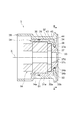
- FIG. 1 is a cross-sectional view showing a centrifugal compressor according to an embodiment of the present disclosure.
- FIG. 2 is a cross-sectional view showing the motor housing in FIG.
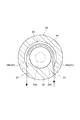
- FIG. 3 is a cross-sectional view taken along the line III-III in FIG.
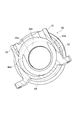
- FIG. 4 is a perspective view showing the inner housing in FIG.
- FIG. 5 is a perspective view showing the outer housing in FIG.
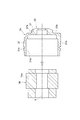
- FIG. 6 is a cross-sectional view showing a first stage of the assembly process.
- FIG. 7 is a cross-sectional view showing a second stage of the assembly process.
- An electric compressor includes a rotating shaft on which a compressor impeller is attached, a stator unit disposed around the rotating shaft, and a motor housing that houses the stator unit, and the motor housing is a stator.
- An inner housing including a first cylindrical portion surrounding and holding the portion; and an outer housing including a second cylindrical portion surrounding and holding the first cylindrical portion of the inner housing; Between the outer surface and the inner surface of the outer housing, a cooling jacket portion is formed over a portion or the entire circumference of the circumferential direction of the rotation shaft, and the inner housing is provided continuously to the first cylindrical portion. It has a first end wall portion extending radially inward of the outer peripheral portion of the stator portion.
- the heat generating portion (motor or the like) of the electric compressor when the cooling fluid flows through the cooling jacket portion, the heat generating portion (motor or the like) of the electric compressor can be cooled via the inner housing.
- the stator portion can be cooled by the first tubular portion.
- the first end wall portion extends radially inward of the outer peripheral portion of the stator portion.
- the cooling jacket portion is formed in a circumferential direction and includes a first end and a second end that are inlets and outlets for the cooling fluid.
- the cooling fluid flows from the first end to the second end or from the second end to the first end. Since the stagnation and uneven flow of the cooling fluid can be suppressed, the cooling efficiency is further improved.
- the position of the inlet and outlet for the cooling fluid may vary depending on the configuration of the peripheral equipment where the electric compressor is installed, but such a change may be made by appropriately changing the position of the cooling jacket (the positions of the first and second ends). It can respond flexibly.
- an abutment surface is formed between the outer surface of the inner housing and the inner surface of the outer housing, with which the outer surface of the inner housing abuts the inner surface of the outer housing.
- One includes a recessed portion which is recessed with respect to the contact surface and which forms a cooling jacket portion, and the recessed portion of the inner housing or the outer housing is formed only in a part of the circumferential direction. Is formed in a part of the circumferential direction. In this case, by appropriately changing the position (range) and the size of the recessed portion, it is possible to arbitrarily form the cooling jacket portion described above.
- the motor housing includes a bearing provided in the motor housing for supporting the rotation shaft, and the first end wall of the inner housing includes an annular portion through which the rotation shaft passes and which surrounds the bearing, the annular portion Holding the bearing.
- the bearing may be cooled via the annular portion of the first end wall. Not only the motor but also the bearings can be cooled efficiently.
- the electric compressor 1 according to the first embodiment will be described with reference to FIG.
- the electric compressor 1 is applied to, for example, an internal combustion engine of a vehicle or a ship.
- the electric compressor 1 includes a compressor 7.
- the electric compressor 1 rotates the compressor impeller 8 by the interaction of the rotor portion 13 and the stator portion 14 to compress a gas such as air and generate compressed air.
- the motor 5 is formed by the rotor portion 13 and the stator portion 14.
- the electric compressor 1 includes a rotating shaft 12 rotatably supported in a housing 2 and a compressor impeller 8 attached to the tip of the rotating shaft 12.
- the housing 2 includes a motor housing 3 for housing the rotor portion 13 and the stator portion 14, an inverter housing 4 for closing an opening on the second end side (left side in the drawing) of the motor housing 3, and a compressor housing 6 for housing the compressor impeller 8.
- the compressor housing 6 is provided on the first end side (right side in the drawing) of the motor housing 3.
- the compressor housing 6 includes an inlet 9, a scroll portion 10 and an outlet 11.
- the rotor portion 13 is fixed to a central portion in the direction of the rotation axis X of the rotation shaft 12 and includes one or more permanent magnets (not shown) attached to the rotation shaft 12.
- the stator portion 14 is held on the inner surface of the motor housing 3 so as to surround the rotor portion 13. That is, the stator portion 14 is disposed around the rotation shaft 12.
- the stator portion 14 includes a cylindrical core portion 14a disposed so as to surround the rotor portion 13, and a coil portion 14b formed by winding a conducting wire (not shown) around the core portion 14a.
- the electric compressor 1 includes two bearings 20A and 20B that rotatably support the rotating shaft 12 with respect to the housing 2.
- the bearings 20A and 20B are provided in the motor housing 3.
- the bearings 20A and 20B are disposed so as to sandwich the motor 5 and support the rotary shaft 12 at both ends.
- the first bearing 20A is held by an annular portion 37 provided at an end of the motor housing 3 on the compressor impeller 8 side.
- the second bearing 20 ⁇ / b> B is held on the inner surface side (the compressor impeller 8 side) of the partition 4 a of the inverter housing 4.
- the motor housing 3 has a cylindrical inner housing 3A disposed on the inner side, ie, the rotary shaft 12 side, and a cylindrical outer housing 3B disposed on the outer side, ie, the outer peripheral side of the inner housing 3A. That is, the motor housing 3 has a structure divided into two.
- the inner housing 3A and the outer housing 3B are separate from each other and arranged concentrically with the rotation axis X.
- Inner housing 3A is attached to outer housing 3B by, for example, an interference fit (shrink fit or the like).
- the inner housing 3A surrounds and holds the stator portion 14.
- the stator portion 14 is attached to the inner housing 3A by, for example, shrink fitting or press fitting. Thereby, the inner housing 3A and the stator portion 14 are unitized.
- the outer housing 3B surrounds and holds the inner housing 3A.
- the unitized inner housing 3A and the stator portion 14 are attached to the outer housing 3B by, for example, an interference fit (shrink fit or the like).
- the inner housing 3A includes a cylindrical first cylindrical portion 31 extending in the direction of the rotation axis X, and a first end wall provided continuously on the first end side (the compressor impeller 8 side) of the first cylindrical portion 31. And a unit 33.
- the first tubular portion 31 surrounds and holds the stator portion 14.
- the second end (opposite to the first end wall portion 33) of the first tubular portion 31 is open.
- the first end wall portion 33 extends radially inward from the first end of the first tubular portion 31 (see FIGS. 4 and 6).
- the first end wall portion 33 includes an annular portion 37 provided on the center side, that is, on the rotation axis X side.
- the annular portion 37 protrudes from the first end of the first tubular portion 31 in the rotation axis X direction (the compressor impeller 8 side).
- An annular outer surface 33 b is formed around the annular portion 37.
- the outer surface 33 b is a shoulder provided between the first tubular portion 31 and the annular portion 37.
- the outer surface 33 b is a flat surface extending in a direction perpendicular to the rotation axis X.
- the annular portion 37 is disposed around the rotation axis X.
- a through hole 37 d is provided at the center of the annular portion 37.
- the boss 8 b of the compressor impeller 8 and the rotary shaft 12 are inserted into the through hole 37 d, and the rotary shaft 12 penetrates the annular portion 37.
- the annular portion 37 extends inward in the radial direction from the outer peripheral portion of the stator portion 14.
- the annular portion 37 surrounds the first bearing 20A.
- the annular portion 37 includes a cylindrical bearing accommodating portion continuous with the through hole 37d, and holds the first bearing 20A at the inner circumferential surface 37c.
- the outer housing 3B has a cylindrical second cylindrical portion 32 extending in the direction of the rotation axis X, and a second end wall portion 34 continuously provided on the first end side of the second cylindrical portion 32.
- the second cylindrical portion 32 surrounds and holds the first cylindrical portion 31 of the inner housing 3A.
- the second end of the second tubular portion 32 is open.
- the second end wall portion 34 extends radially inward from the first end of the second tubular portion 32.
- the second end wall portion 34 has an annular shape and is disposed around the rotation axis X.
- the inner surface 34 b in the radial direction of the second end wall portion 34 is a flat surface extending in a direction perpendicular to the rotation axis X.
- An opening is formed at the center of the second end wall portion 34, and the annular portion 37 of the inner housing 3A is disposed in the opening. As shown in FIG. 1, in the opening of the second end wall portion 34, an annular portion 37 and a first bearing 20A are disposed.
- the inner housing 3A is inserted from the second end side of the outer housing 3B and fitted into the outer housing 3B.
- the inner housing 3A is fitted in the outer housing 3B while holding the stator portion 14.
- the outer peripheral surface 31 a of the first cylindrical portion 31 abuts on the inner peripheral surface 32 a of the second cylindrical portion 32.
- the outer peripheral surface 31a may be in close contact with the inner peripheral surface 32a.
- the cylindrical first contact surface S1 is formed by the outer peripheral surface 31a and the inner peripheral surface 32a.
- An annular first seal member 36 is provided between the outer circumferential surface 31 a and the inner circumferential surface 32 a.
- the first seal member 36 is provided in one seal groove 31 c (see FIG. 6) formed in the outer peripheral surface 31 a of the first tubular portion 31.
- the first seal member 36 is, for example, an O-ring.
- the outer surface 33 b of the first end wall 33 abuts the inner surface 34 b of the second end wall 34.
- the outer surface 33b may abut against the inner surface 34b.
- a flat and annular second contact surface S2 is formed by the outer surface 33b and the inner surface 34b.
- An outer circumferential surface 37 a of the annular portion 37 is in contact with an inner circumferential surface 34 a of the second end wall portion 34.
- the first end wall 33 and the second end wall 34 face the back surface 8 a of the compressor impeller 8 with a slight gap (see FIG. 1).
- the outer circumferential surface 37a may be in close contact with the inner circumferential surface 34a.
- An annular second seal member 38 is provided between the outer circumferential surface 37 a and the inner circumferential surface 34 a.
- the second seal member 38 is provided in one seal groove 37 b (see FIG. 6) formed in the outer peripheral surface 37 a of the annular portion 37.
- the second seal member 38 is, for example, an O-ring.
- the inner housing 3A and the outer housing 3B may be held at either the outer peripheral surface 31a and the inner peripheral surface 32a, or at the outer peripheral surface 37a and the inner peripheral surface 34a.
- the outer peripheral surface 31a and the inner peripheral surface 32a may be interference fit (shrink fitting etc.), and the outer peripheral surface 37a and the inner peripheral surface 34a may be clearance fit with each other.
- the outer peripheral surface 31a and the inner peripheral surface 32a may be clearance fit with each other, and the outer peripheral surface 37a and the inner peripheral surface 34a may be interference fit (shrink fitting etc.).
- a clearance may be formed between the clearance fitted outer peripheral surface 37a and the inner peripheral surface 34a, or between the clearance fitted outer peripheral surface 31a and the inner peripheral surface 32a.
- Inner housing 3A and outer housing 3B are made of the same material.
- Inner housing 3A and outer housing 3B are made of, for example, aluminum.
- the inner housing 3A is attached within the outer housing 3B by, for example, shrink fitting. At the time of assembly, assembly is possible by warming only the outer housing 3B. If the inner housing 3A and the outer housing 3B are made of the same material, the interference hardly changes even if both thermally expand during use.
- Inner housing 3A and outer housing 3B can each be manufactured, for example, by die casting or the like.
- the inner housing 3A and the outer housing 3B can be easily manufactured because they are molded in a method that does not use a core.
- the inner peripheral surface 32a of the outer housing 3B has a draft.
- the outer peripheral surface 31a of the inner housing 3A may have a draft.
- the inner circumferential surface 32a of the outer housing 3B and / or the outer circumferential surface 31a of the inner housing 3A are machined to remove the draft. It is also good.
- the electric compressor 1 of the present embodiment has a structure for cooling components provided inside the motor housing 3 via the motor housing 3. As shown in FIGS. 1 and 2, a cooling water or the like is formed between the inner surface (the inner peripheral surface 32a and the inner surface 34b) of the outer housing 3B and the outer surface (the outer peripheral surface 31a and the outer surface 33b) of the inner housing 3A. A water cooling jacket portion 40 is formed to circulate the cooling fluid.
- the water cooling jacket portion 40 is formed only in a part of the circumferential direction. As shown in FIG. 3 to FIG. 5, the water cooling jacket portion 40 is formed by respectively forming a recess 43 and a recess 44 in the inner housing 3A and the outer housing 3B, and combining them. In other words, the water cooling jacket portion 40 is a space formed so as to be enclosed between the recess 43 and the recess 44.
- the inner surface 34b of the outer housing 3B is formed with a recess 44 which is recessed with respect to the second contact surface S2.
- the recess 44 extends in the circumferential direction and is formed only in a part of the circumferential direction. In other words, the recess 44 has a rotationally asymmetric shape with respect to the rotation axis X.
- the recess 44 may be provided in the range of 180 ° or more and less than 360 °.
- the recess 44 includes a first end 44a and a second end 44b.
- a flat inner surface forming the second contact surface S2 in a portion where the recess 44 is not formed, that is, between the first end 44a and the second end 44b (a range of more than 0 ° and less than 180 °). 34b is formed.
- the inner housing 3A is recessed with respect to the first contact surface S1 and the second contact surface S2.
- the hollow portion 43 is formed.
- the recess 43 extends in the circumferential direction and is formed only in a part of the circumferential direction. In other words, the recess 43 has a rotationally asymmetric shape with respect to the rotation axis X.
- the recess 43 may be provided in the range of 180 ° or more and less than 360 °.
- the recess 43 includes a first end 43a and a second end 43b.
- the first contact surface S1 and the second contact are not formed between the first end 43a and the second end 43b (in the range of more than 0 ° and less than 180 °).
- the outer peripheral surface 31a and the outer surface 33b which make surface S2 are formed.
- the recess 43 may be provided in a range corresponding to the recess 44.
- the recessed portion 43 is aligned (communicated) with the recessed portion 44.
- the position of the first end 44a may substantially coincide with the position of the first end 43a.
- the position of the second end 44 b may substantially coincide with the position of the second end 43 b.
- the water cooling jacket portion 40 has a rotationally asymmetric shape with respect to the rotation axis X.
- the water cooling jacket portion 40 includes a first end 41 composed of a first end 43a and a first end 44a, and a second end 42 composed of a second end 43b and a second end 44b.
- the range in which the water cooling jacket portion 40 is provided, the shape of the water cooling jacket portion 40, and the like can be appropriately changed by changing the range in which the depression portion 43 and the depression portion 44 are formed and the shape of the depression portion 43 and the depression portion 44. .
- the recess 43 and the recess 44 can be easily formed by die casting.
- the water-cooled jacket portion 40 faces the outer peripheral surface 31a and the outer surface 33b of the inner housing 3A.
- the cooling fluid cools the first tubular portion 31 and the first end wall portion 33 (including the annular portion 37).
- the cooled first tubular portion 31 and the first end wall portion 33 can cool components provided inside the motor housing 3 that can generate heat.
- the outer housing 3B may be provided with an inflow pipe 51 and an outflow pipe 52 connected to the first end 43a and the second end 43b of the inner housing 3A, respectively.
- External pipes, pumps, and the like are connected to the inflow pipe 51 and the outflow pipe 52 to allow the cooling fluid to flow.
- FIGS. 6 and 7 A method of assembling the motor housing 3 will be described with reference to FIGS. 6 and 7.
- the stator portion 14 is attached to the inner housing 3A by shrink fitting or press fitting.
- the stator portion 14 is inserted in the direction of the rotation axis X from the second end side (left side in the drawing) of the inner housing 3A.
- the inner housing 3A and the stator portion 14 are unitized.
- the first seal member 36 and the second seal member 38 are attached to the seal groove 31c and the seal groove 37b of the inner housing 3A.
- the unitized inner housing 3A and the stator portion 14 are attached to the outer housing 3B by shrink fitting.
- the inner housing 3A is inserted from the second end side (left side in the drawing) of the outer housing 3B in the rotation axis X direction.
- the heat generating portion (motor 5 etc.) of the electric compressor 1 can be cooled via the inner housing 3A.
- the stator portion 14 can be cooled by the first tubular portion 31.
- the first end wall portion 33 extends radially inward of the outer peripheral portion of the stator portion 14.
- the motor housing 3 has the inner housing 3A and the outer housing 3B. In other words, the motor housing 3 is divided into the inner housing 3A and the outer housing 3B. These housings are combined to form the water cooling jacket portion 40. Further, a first seal member 36 and a second seal member 38 are installed on the front and back of the water cooling jacket portion 40, and a water cooling mechanism is provided.
- a channel shape corresponding to the inlet / outlet position of the cooling fluid is realized by forming the rotationally asymmetric recess portions 43 and 44 in the abutting portions of the inner housing 3A and the outer housing 3B.
- the outer shape of the outer housing 3B may be changed only for the shape of the compressor impeller 8, the shapes of the inverter housing 4 and the compressor housing 6, or the difference in mounting bosses. There is no need to change the inner surface side of the outer housing 3B and the inner housing 3A, and commonality is achieved.
- the water-cooled jacket portion 40 is not a closed space at the time of manufacturing each housing, so the core becomes unnecessary. For this reason, manufacture by die casting etc. is attained. Since the inner housing 3A and the outer housing 3B are molded by a method such as die casting which does not use a core, the manufacture is easy. When assembling the outer housing 3B and the inner housing 3A, assembly is possible by warming only the outer housing 3B. In use, the inner housing 3A and the outer housing 3B can thermally expand, but if the same material is used, the interference hardly changes. Therefore, the outer housing 3B can reliably hold the inner housing 3A at the time of use.
- the cooling fluid is prevented from leaking to the outside.
- the flow passage range in the circumferential direction can be changed by changing the shape of the abutment portion.
- the position of the cooling fluid inlet / outlet can be made flexible.
- the cooling fluid flows from the first end 41 to the second end 42 in the rotationally asymmetric water cooling jacket 40.
- the position of the inlet and outlet for the cooling fluid may be changed depending on the configuration of the peripheral equipment where the electric compressor 1 is installed, but the position of the water cooling jacket 40 (the positions of the first end 41 and the second end 42) should be changed appropriately. Can respond flexibly to such changes.
- the second end wall portion of the outer housing 3B may not extend inward from the outer peripheral portion of the stator portion 14.
- the second end wall of the outer housing 3B may be omitted.
- the first end wall of the inner housing 3A may face the entire surface of the rear surface 8a of the compressor impeller 8.
- the water cooling jacket portion 40 may be formed by any one of the recess 43 and the recess 44. It is not limited to the form in which the water cooling jacket portion 40 is formed only by the recessed portions 43 and 44. Even if the water cooling jacket portion 40 is formed by the recessed portions 43 and 44 provided over the entire circumference, and a partition member or the like separate from the inner housing 3A or the outer housing 3B is provided in a part of the water cooling jacket portion 40 Good.
- the partition member may be installed in the water cooling jacket portion 40 to define the flow path shape.
- the water cooling jacket may be formed on the entire circumferential direction (i.e., the entire circumference).
- the cooling fluid is not limited to water, and may be another liquid such as oil.
- the present invention may be applied to an electric compressor provided with a turbine.
Landscapes
- Engineering & Computer Science (AREA)
- Mechanical Engineering (AREA)
- General Engineering & Computer Science (AREA)
- Chemical & Material Sciences (AREA)
- Combustion & Propulsion (AREA)
- Physics & Mathematics (AREA)
- Thermal Sciences (AREA)
- Power Engineering (AREA)
- Structures Of Non-Positive Displacement Pumps (AREA)
Abstract
電動コンプレッサは、コンプレッサインペラが取り付けられた回転軸と、回転軸の周囲に配置されるステータ部と、ステータ部を収納するモータハウジングと、を備える。モータハウジングは、ステータ部を包囲して保持する第1筒状部を含むインナーハウジングと、その第1筒状部を包囲して保持する第2筒状部を含むアウターハウジングと、を有する。インナーハウジングの外面とアウターハウジングの内面との間には、回転軸の周方向の一部または全周にわたって冷却ジャケット部が形成される。インナーハウジングは、第1筒状部に連続して設けられ、回転軸の径方向においてステータ部の外周部よりも内側まで延びる第1端壁部を有する。
Description
本開示は、電動コンプレッサに関する。
従来、特許文献1および2に記載された電動過給機が知られている。電動過給機は、モータステータおよびモータロータを備えている。特許文献1に記載された電動過給機は、モータステータと、モータステータを支持するアウタースリーブとが一体化されたステータアッセンブリを備える。アウタースリーブとベアリングハウジングとの間には、水冷ジャケットが設けられている。特許文献2に記載された電動過給機においても、モータステータの周囲に空間が設けられている。
上記した従来の電動過給機(電動コンプレッサ)では、ステータ部の冷却が考慮されているが、コンプレッサインペラと共に回転する回転体(回転軸など)の周辺には、熱を発生させる要素が他にも存在する。そこで、電動コンプレッサ全体に対する更なる冷却効率の向上が求められている。本開示は、冷却効率の向上を可能とする電動コンプレッサを説明する。
本開示の一態様に係る電動コンプレッサは、コンプレッサインペラが取り付けられた回転軸と、回転軸の周囲に配置されるステータ部と、ステータ部を収納するモータハウジングと、を備え、モータハウジングは、ステータ部を包囲して保持する第1筒状部を含むインナーハウジングと、インナーハウジングの第1筒状部を包囲して保持する第2筒状部を含むアウターハウジングと、を有し、インナーハウジングの外面とアウターハウジングの内面との間には、回転軸の周方向の一部または全周にわたって冷却ジャケット部が形成され、インナーハウジングは、第1筒状部に連続して設けられ、回転軸の径方向においてステータ部の外周部よりも内側まで延びる第1端壁部を有する。
本開示の一態様によれば、冷却効率の向上が可能である。
本開示の一態様に係る電動コンプレッサは、コンプレッサインペラが取り付けられた回転軸と、回転軸の周囲に配置されるステータ部と、ステータ部を収納するモータハウジングと、を備え、モータハウジングは、ステータ部を包囲して保持する第1筒状部を含むインナーハウジングと、インナーハウジングの第1筒状部を包囲して保持する第2筒状部を含むアウターハウジングと、を有し、インナーハウジングの外面とアウターハウジングの内面との間には、回転軸の周方向の一部または全周にわたって冷却ジャケット部が形成され、インナーハウジングは、第1筒状部に連続して設けられ、回転軸の径方向においてステータ部の外周部よりも内側まで延びる第1端壁部を有する。
この電動コンプレッサによれば、冷却ジャケット部に冷却流体が流れることにより、インナーハウジングを介して、電動コンプレッサの発熱部分(モータ等)が冷却され得る。第1筒状部によって、ステータ部が冷却され得る。加えて、第1端壁部は、径方向において、ステータ部の外周部よりも内側まで延びている。この第1端壁部により、モータのみならず、回転軸の周辺の別の発熱部分も冷却され得る。したがって、冷却効率の向上が可能になっている。
いくつかの態様において、冷却ジャケット部は、周方向の一部に形成されており、冷却流体の出入口である第1端部および第2端部を含む。この場合、冷却流体が第1端部から第2端部へ、または第2端部から第1端部へと流れる。冷却流体の滞留や偏流を抑制できるので、冷却効率が一層向上する。冷却流体の出入口の位置は、電動コンプレッサが設置される周辺の機器構成によって変わり得るが、冷却ジャケット部の位置(第1および第2端部の位置)を適宜変更することにより、そのような変化にも柔軟に対応し得る。
いくつかの態様において、インナーハウジングの外面とアウターハウジングの内面との間には、インナーハウジングの外面とアウターハウジングの内面とが当接する当接面が形成されており、インナーハウジングおよびアウターハウジングの少なくとも一方は、当接面に対して窪むと共に冷却ジャケット部を形成する窪み部を含み、インナーハウジングまたはアウターハウジングの窪み部は、周方向の一部のみに形成されていることにより、冷却ジャケット部は周方向の一部に形成されている。この場合、窪み部の位置(範囲)や大きさを適宜変更することにより、上記した冷却ジャケット部の任意な形成が可能となる。
いくつかの態様において、モータハウジング内に設けられて回転軸を支持する軸受を備え、インナーハウジングの第1端壁部は、回転軸が貫通すると共に軸受を包囲する環状部を含み、環状部は軸受を保持している。この場合、第1端壁部の環状部を介して軸受が冷却され得る。モータのみならず、軸受を効率的に冷却することができる。
以下、本開示の実施形態について、図面を参照しながら説明する。なお、図面の説明において同一要素には同一符号を付し、重複する説明は省略する。以下の説明において、特に断らない限り、「径方向」および「周方向」との語は、回転軸12或いは回転軸線Xを基準として用いられる。
図1を参照して、第1実施形態の電動コンプレッサ1について説明する。図1に示されるように、電動コンプレッサ1は、たとえば車両や船舶の内燃機関に適用されるものである。電動コンプレッサ1は、コンプレッサ7を備えている。電動コンプレッサ1は、ロータ部13およびステータ部14の相互作用によってコンプレッサインペラ8を回転させ、空気等の気体を圧縮し、圧縮空気を発生させる。ロータ部13およびステータ部14によってモータ5が形成されている。
電動コンプレッサ1は、ハウジング2内で回転可能に支持された回転軸12と、回転軸12の先端部に取り付けられたコンプレッサインペラ8とを備える。ハウジング2は、ロータ部13およびステータ部14を収納するモータハウジング3と、モータハウジング3の第2端側(図示左側)の開口を閉鎖するインバータハウジング4と、コンプレッサインペラ8を収納するコンプレッサハウジング6とを備える。コンプレッサハウジング6は、モータハウジング3の第1端側(図示右側)に設けられている。コンプレッサハウジング6は、吸入口9と、スクロール部10と、吐出口11とを含んでいる。
ロータ部13は、回転軸12の回転軸線X方向の中央部に固定されており、回転軸12に取り付けられた1または複数の永久磁石(図示せず)を含む。ステータ部14は、ロータ部13を包囲するようにしてモータハウジング3の内面に保持されている。すなわち、ステータ部14は、回転軸12の周囲に配置されている。ステータ部14は、ロータ部13を包囲するように配置された円筒状のコア部14aと、コア部14aに導線(図示せず)が巻回されてなるコイル部14bとを含む。導線を通じてステータ部14のコイル部14bに交流電流が流されると、ロータ部13およびステータ部14の相互作用によって、回転軸12とコンプレッサインペラ8とが一体になって回転する。コンプレッサインペラ8が回転すると、コンプレッサインペラ8は、吸入口9を通じて外部の空気を吸入し、スクロール部10を通じて空気を圧縮し、吐出口11から吐出する。吐出口11から吐出された圧縮空気は、前述の内燃機関に供給される。
電動コンプレッサ1は、ハウジング2に対して回転軸12を回転可能に支持する2個の軸受20A,20Bを備える。軸受20A,20Bは、モータハウジング3内に設けられている。軸受20A,20Bは、モータ5を挟むように配置され、回転軸12を両持ちで支持している。第1の軸受20Aは、モータハウジング3のコンプレッサインペラ8側の端部に設けられた環状部37に保持されている。第2の軸受20Bは、インバータハウジング4の隔壁部4aの内面側(コンプレッサインペラ8側)に保持されている。
続いて、図1および図2を参照して、モータハウジング3の構成についてより詳細に説明する。モータハウジング3は、内側すなわち回転軸12側に配置される円筒状のインナーハウジング3Aと、外側すなわちインナーハウジング3Aの外周側に配置される円筒状のアウターハウジング3Bとを有する。すなわち、モータハウジング3は、2分割された構造を有する。インナーハウジング3Aとアウターハウジング3Bとは別体であり、回転軸線Xに対して同心状に配置される。インナーハウジング3Aは、たとえば締まり嵌め(焼嵌め等)により、アウターハウジング3Bに取り付けられている。
インナーハウジング3Aは、ステータ部14を包囲して保持している。ステータ部14は、たとえば焼嵌め若しくは圧入などにより、インナーハウジング3Aに取り付けられている。これにより、インナーハウジング3Aおよびステータ部14はユニット化されている。アウターハウジング3Bは、インナーハウジング3Aを包囲して保持している。ユニット化されたインナーハウジング3Aおよびステータ部14は、たとえば締まり嵌め(焼嵌め等)により、アウターハウジング3Bに取り付けられている。
インナーハウジング3Aは、回転軸線X方向に延びる円筒状の第1筒状部31と、第1筒状部31の第1端側(コンプレッサインペラ8側)に連続して設けられた第1端壁部33とを有する。第1筒状部31は、ステータ部14を包囲して保持している。第1筒状部31の第2端(第1端壁部33と反対側)は開放されている。第1端壁部33は、第1筒状部31の第1端から、径方向の内方に延びている(図4および図6参照)。
第1端壁部33は、中心側すなわち回転軸線X側に設けられた環状部37を含む。環状部37は、第1筒状部31の第1端よりも回転軸線X方向(コンプレッサインペラ8側)に突出している。環状部37の周囲には、円環状の外面33bが形成されている。外面33bは、第1筒状部31と環状部37との間に設けられた肩部である。外面33bは、回転軸線Xに垂直な方向に延びる平坦面である。環状部37は、回転軸線Xを中心に配置されている。環状部37の中央には、貫通孔37dが設けられている。コンプレッサインペラ8のボス部8bおよび回転軸12が、この貫通孔37dに挿通されており、回転軸12が環状部37を貫通している。
図1に示されるように、環状部37は、径方向において、ステータ部14の外周部よりも内側まで延びている。環状部37は、第1の軸受20Aを包囲している。環状部37は、貫通孔37dに連続する円筒状の軸受収容部を含んでおり、内周面37cにおいて第1の軸受20Aを保持している。
アウターハウジング3Bは、回転軸線X方向に延びる円筒状の第2筒状部32と、第2筒状部32の第1端側に連続して設けられた第2端壁部34とを有する。第2筒状部32は、インナーハウジング3Aの第1筒状部31を包囲して保持している。第2筒状部32の第2端は開放されている。第2端壁部34は、第2筒状部32の第1端から、径方向の内方に延びている。図2、図5および図7に示されるように、第2端壁部34は、円環状をなしており、回転軸線Xを中心に配置されている。第2端壁部34の径方向における内面34bは、回転軸線Xに垂直な方向に延びる平坦面である。第2端壁部34の中央には開口が形成されており、この開口内に、インナーハウジング3Aの環状部37が配置されている。図1に示されるように、第2端壁部34の開口内に、環状部37および第1の軸受20Aが配置されている。
図2および図7に示されるように、インナーハウジング3Aは、アウターハウジング3Bの第2端側から挿入され、アウターハウジング3B内に嵌め込まれる。インナーハウジング3Aは、ステータ部14を保持した状態で、アウターハウジング3B内に嵌め込まれる。第1筒状部31の外周面31aは、第2筒状部32の内周面32aに当接する。外周面31aは内周面32aに密着してもよい。外周面31aと内周面32aとによって、円筒状の第1当接面S1が形成されている。外周面31aと内周面32aとの間には、環状の第1シール部材36が設けられている。第1シール部材36は、第1筒状部31の外周面31aに形成された1本のシール溝31c(図6参照)に設けられている。第1シール部材36は、たとえばOリングである。
第1端壁部33の外面33bは、第2端壁部34の内面34bに当接している。外面33bは、内面34bに突き当てられてもよい。外面33bと内面34bとによって、平坦な円環状の第2当接面S2が形成されている。環状部37の外周面37aは、第2端壁部34の内周面34aに当接している。第1端壁部33および第2端壁部34は、コンプレッサインペラ8の背面8aに対し、僅かな隙間をもって対面している(図1参照)。外周面37aは内周面34aに密着してもよい。外周面37aと内周面34aとの間には、環状の第2シール部材38が設けられている。第2シール部材38は、環状部37の外周面37aに形成された1本のシール溝37b(図6参照)に設けられている。第2シール部材38は、たとえばOリングである。
インナーハウジング3Aとアウターハウジング3Bとは、外周面31aと内周面32a、または、外周面37aと内周面34aのいずれかの箇所で保持されればよい。外周面31aと内周面32aが互いに締まり嵌め(焼嵌め等)され、外周面37aと内周面34aが互いに隙間嵌めされてもよい。これとは反対に、外周面31aと内周面32aが互いに隙間嵌めされ、外周面37aと内周面34aが互いに締まり嵌め(焼嵌め等)されてもよい。隙間嵌めされた外周面37aと内周面34aの間、または、隙間嵌めされた外周面31aと内周面32aの間には、隙間が形成されてもよい。いずれかの箇所を締まり嵌めで組み付けることにより、たとえば、アウターハウジング3Bに対するインナーハウジング3Aの位置合わせが容易となる。
インナーハウジング3Aおよびアウターハウジング3Bは、同一の材料からなる。インナーハウジング3Aおよびアウターハウジング3Bは、たとえば、アルミニウム製である。上記したように、インナーハウジング3Aは、たとえば焼嵌めによってアウターハウジング3B内に取り付けられる。組立時には、アウターハウジング3Bのみを温めることで、組立てが可能である。インナーハウジング3Aおよびアウターハウジング3Bは同一の材料とすると、使用時に両方が熱膨張した場合でも、締め代はほとんど変化しない。
インナーハウジング3Aおよびアウターハウジング3Bは、それぞれ、たとえばダイキャスト等によって製作され得る。インナーハウジング3Aおよびアウターハウジング3Bは、中子を使用しない方法で成型されるため、簡単に製造され得る。なお、ダイキャスト等によってインナーハウジング3Aおよびアウターハウジング3Bが製造される場合、アウターハウジング3Bの内周面32aには、抜き勾配がつく。型の形状によっては、インナーハウジング3Aの外周面31aに抜き勾配がつく場合もある。インナーハウジング3Aおよびアウターハウジング3Bの嵌め合いを容易に行うため、アウターハウジング3Bの内周面32aおよび/またはインナーハウジング3Aの外周面31aに対し、抜き勾配を除去するための機械加工が施されてもよい。
本実施形態の電動コンプレッサ1は、モータハウジング3を介して、モータハウジング3の内部に備わる部品類を冷却するための構造を有している。図1および図2に示されるように、アウターハウジング3Bの内面(内周面32aおよび内面34b)と、インナーハウジング3Aの外面(外周面31aおよび外面33b)との間には、冷却水等の冷却流体を流通させるための水冷ジャケット部40が形成されている。
図3に示されるように、水冷ジャケット部40は、周方向の一部のみに形成されている。図3~図5に示されるように、水冷ジャケット部40は、インナーハウジング3Aおよびアウターハウジング3Bに、窪み部43および窪み部44がそれぞれ形成され、これらが合わさることで形成されている。言い換えると、水冷ジャケット部40は、窪み部43と窪み部44との間に囲まれて形成される空間である。
図3および図5に示されるように、アウターハウジング3Bの内面34bには、第2当接面S2に対して窪む窪み部44が形成されている。窪み部44は、周方向に延び、周方向の一部にのみ形成されている。言い換えれば、窪み部44は、回転軸線Xに関して、回転非対称な形状をなしている。窪み部44は、180°以上360°未満の範囲に設けられてもよい。窪み部44は、第1端部44aおよび第2端部44bを含む。窪み部44が形成されていない部分、すなわち第1端部44aと第2端部44bとの間(0°より大きく180°未満の範囲)には、第2当接面S2をなす平坦な内面34bが形成されている。
図4に示されるように、インナーハウジング3Aにおける第1筒状部31と第1端壁部33とが連続する部分には、第1当接面S1および第2当接面S2に対して窪む窪み部43が形成されている。窪み部43は、周方向に延び、周方向の一部にのみ形成されている。言い換えれば、窪み部43は、回転軸線Xに関して、回転非対称な形状をなしている。窪み部43は、180°以上360°未満の範囲に設けられてもよい。窪み部43は、第1端部43aおよび第2端部43bを含む。窪み部43が形成されていない部分、すなわち第1端部43aと第2端部43bとの間(0°より大きく180°未満の範囲)には、第1当接面S1および第2当接面S2をなす外周面31aおよび外面33bが形成されている。
窪み部43は、窪み部44に対応する範囲に設けられてもよい。アウターハウジング3Bにインナーハウジング3Aが取り付けられた状態で、窪み部44に窪み部43が合わさる(連通する)。第1端部44aの位置が、第1端部43aの位置に略一致してもよい。第2端部44bの位置が、第2端部43bの位置に略一致してもよい。水冷ジャケット部40は、回転軸線Xに関して、回転非対称な形状をなしている。水冷ジャケット部40は、第1端部43aおよび第1端部44aからなる第1端部41と、第2端部43bおよび第2端部44bからなる第2端部42とを含む。水冷ジャケット部40が設けられる範囲や水冷ジャケット部40の形状等は、窪み部43および窪み部44を形成する範囲や窪み部43および窪み部44の形状を変更することにより、適宜変更可能である。窪み部43および窪み部44は、ダイキャスト法によって容易に形成され得る。
水冷ジャケット部40は、インナーハウジング3Aの外周面31aおよび外面33bに対面している。したがって、冷却流体は、第1筒状部31および第1端壁部33(環状部37を含む)を冷却する。冷却された第1筒状部31および第1端壁部33により、モータハウジング3の内部に設けられた、熱を発生し得る部品類が冷却され得る。
図3および図5に示されるように、アウターハウジング3Bには、インナーハウジング3Aの第1端部43aおよび第2端部43bにそれぞれ接続される流入管51および流出管52が設けられてもよい。流入管51および流出管52には、外部の配管およびポンプ等が接続され、冷却流体が流通させられる。
図6および図7を参照して、モータハウジング3の組立方法について説明する。図6に示されるように、インナーハウジング3Aに対して、ステータ部14を焼嵌めまたは圧入により取り付ける。この際、ステータ部14は、インナーハウジング3Aの第2端側(図示左側)から回転軸線X方向に挿入される。これにより、インナーハウジング3Aおよびステータ部14がユニット化される。
図7に示されるように、インナーハウジング3Aのシール溝31cおよびシール溝37bに、第1シール部材36および第2シール部材38をそれぞれ取り付ける。アウターハウジング3Bに対して、ユニット化されたインナーハウジング3Aおよびステータ部14を焼嵌めにより取り付ける。この際、インナーハウジング3Aは、アウターハウジング3Bの第2端側(図示左側)から回転軸線X方向に挿入される。以上の工程を経て、モータハウジング3およびステータ部14からなるユニットが得られる。
本実施形態の電動コンプレッサ1によれば、水冷ジャケット部40に冷却流体が流れることにより、インナーハウジング3Aを介して、電動コンプレッサ1の発熱部分(モータ5等)が冷却され得る。第1筒状部31によって、ステータ部14が冷却され得る。加えて、第1端壁部33は、径方向において、ステータ部14の外周部よりも内側まで延びている。この第1端壁部33により、モータのみならず、回転軸12の周辺の別の発熱部分も冷却され得る。したがって、冷却効率の向上が可能になっている。
従来、冷却ジャケット部を持つモータハウジングは、中子を使用する鋳造などの方法を使用して製作されていた。ダイキャスト法での製作が困難であったため、コスト高となっていた。また、取り合いやコンプレッサスペックの違いに対して、モータハウジング全体を製作する必要があり、部品共通化の観点から、改良が望まれていた。本実施形態の電動コンプレッサ1によれば、モータハウジング3は、インナーハウジング3Aとアウターハウジング3Bとを有する。言い換えると、モータハウジング3は、インナーハウジング3Aとアウターハウジング3Bに分割されている。これらのハウジングが組み合って水冷ジャケット部40が形成される。また水冷ジャケット部40の前後に第1シール部材36および第2シール部材38を設置し、水冷機構が設けられている。インナーハウジング3Aとアウターハウジング3Bの突き当て部分に、回転非対称な形状の窪み部43,44を形成することで、冷却流体の出入り口位置に対応した水路形状が実現されている。また、コンプレッサインペラ8の形状、インバータハウジング4やコンプレッサハウジング6の形状、または、マウント用ボスの違いに対しても、アウターハウジング3Bの外側の形状を変更するだけでよい。アウターハウジング3Bの内面側とインナーハウジング3Aとは、変更する必要がなく、共通化が図られている。
またモータハウジング3をインナーハウジング3Aとアウターハウジング3Bに分割することで、水冷ジャケット部40が,各々のハウジング製作時に閉空間でなくなるため、中子が不要となる。このため、ダイキャスト等での製作が可能となる。中子を使用しないダイキャスト等の製法でインナーハウジング3Aおよびアウターハウジング3Bが成型されるので、製作が簡単である。アウターハウジング3Bとインナーハウジング3Aの組立時には、アウターハウジング3Bのみを温めることで、組立が可能である。使用時は、インナーハウジング3Aとアウターハウジング3Bが熱膨張し得るが、同一の材料とすると、締め代はほとんど変化しない。このため、使用時において、アウターハウジング3Bはインナーハウジング3Aを確実に保持できる。
また、水冷ジャケット部40の前後に第1シール部材36および第2シール部材38が設置されているので、外部に冷却流体が漏れることを防止する構造となっている。突き当て部の形状を変えることで、円周方向の流路範囲を変えることができる。よって、冷却流体の出入口の位置に柔軟性を持たせることが可能となる。
回転非対称な形状の水冷ジャケット部40では、冷却流体が第1端部41から第2端部42へと流れる。全周に水冷ジャケット部を設けた場合と比較して、冷却流体の滞留や偏流を抑制できるので、冷却効率が一層向上する。冷却流体の出入口の位置は、電動コンプレッサ1が設置される周辺の機器構成によって変わり得るが、水冷ジャケット部40の位置(第1端部41および第2端部42の位置)を適宜変更することにより、そのような変化にも柔軟に対応し得る。
窪み部43,44の位置(範囲)や大きさを適宜変更することにより、水冷ジャケット部40の任意な形成が可能となる。
第1の軸受20Aを保持する環状部37によれば、モータ5のみならず、第1の軸受20Aを効率的に冷却することができる。
以上、本開示の実施形態について説明したが、本発明は上記実施形態に限られない。たとえば、アウターハウジング3Bの第2端壁部は、ステータ部14の外周部より内側まで延びなくてもよい。アウターハウジング3Bの第2端壁部が省略されてもよい。コンプレッサインペラ8の背面8aの全面に、インナーハウジング3Aの第1端壁部が対面してもよい。
窪み部43および窪み部44のいずれか一方によって水冷ジャケット部40が形成されてもよい。窪み部43,44によってのみ水冷ジャケット部40が形成される形態に限られない。全周にわたって設けられた窪み部43,44によって水冷ジャケット部40が形成され、その水冷ジャケット部40の一部に、インナーハウジング3Aまたはアウターハウジング3Bとは別体の仕切り部材などが設けられてもよい。仕切り部材は、水冷ジャケット部40内に設置されて、流路形状を規定し得る。
水冷ジャケット部は周方向の全部(すなわち全周)に形成されてもよい。冷却流体は水に限られず、油等の他の液体であってもよい。タービンを備えた電動コンプレッサに本発明が適用されてもよい。
本開示のいくつかの態様によれば、冷却効率の向上が可能である。
1 電動コンプレッサ
2 ハウジング
3 モータハウジング
3A インナーハウジング
3B アウターハウジング
4 インバータハウジング
4a 隔壁部
5 モータ
6 コンプレッサハウジング
8 コンプレッサインペラ
8a 背面
12 回転軸
14 ステータ部
20A 第1の軸受
20B 第2の軸受
31 第1筒状部
31a 外周面(外面)
32 第2筒状部
32a 内周面(内面)
33 第1端壁部
33b 外面
34 第2端壁部
34a 内周面
34b 内面
36 第1シール部材
37 環状部
37a 外周面
38 第2シール部材
40 水冷ジャケット部(冷却ジャケット部)
41 第1端部
42 第2端部
43 窪み部
44 窪み部
S1 第1当接面
S2 第2当接面
X 回転軸線
2 ハウジング
3 モータハウジング
3A インナーハウジング
3B アウターハウジング
4 インバータハウジング
4a 隔壁部
5 モータ
6 コンプレッサハウジング
8 コンプレッサインペラ
8a 背面
12 回転軸
14 ステータ部
20A 第1の軸受
20B 第2の軸受
31 第1筒状部
31a 外周面(外面)
32 第2筒状部
32a 内周面(内面)
33 第1端壁部
33b 外面
34 第2端壁部
34a 内周面
34b 内面
36 第1シール部材
37 環状部
37a 外周面
38 第2シール部材
40 水冷ジャケット部(冷却ジャケット部)
41 第1端部
42 第2端部
43 窪み部
44 窪み部
S1 第1当接面
S2 第2当接面
X 回転軸線
Claims (6)
- コンプレッサインペラが取り付けられた回転軸と、
前記回転軸の周囲に配置されるステータ部と、
前記ステータ部を収納するモータハウジングと、を備え、
前記モータハウジングは、
前記ステータ部を包囲して保持する第1筒状部を含むインナーハウジングと、
前記インナーハウジングの前記第1筒状部を包囲して保持する第2筒状部を含むアウターハウジングと、を有し、
前記インナーハウジングの外面と前記アウターハウジングの内面との間には、前記回転軸の周方向の一部または全周にわたって冷却ジャケット部が形成され、
前記インナーハウジングは、前記第1筒状部に連続して設けられ、前記回転軸の径方向において前記ステータ部の外周部よりも内側まで延びる第1端壁部を有する、電動コンプレッサ。 - 前記冷却ジャケット部は、前記周方向の一部に形成されており、冷却流体の出入口である第1端部および第2端部を含む、請求項1に記載の電動コンプレッサ。
- 前記インナーハウジングの外面と前記アウターハウジングの内面との間には、前記インナーハウジングの外面と前記アウターハウジングの内面とが当接する当接面が形成されており、
前記インナーハウジングおよび前記アウターハウジングの少なくとも一方は、前記当接面に対して窪むと共に前記冷却ジャケット部を形成する窪み部を含み、
前記インナーハウジングまたは前記アウターハウジングの前記窪み部は、前記周方向の一部のみに形成されていることにより、前記冷却ジャケット部は前記周方向の一部に形成されている、請求項2に記載の電動コンプレッサ。 - 前記モータハウジング内に設けられて前記回転軸を支持する軸受を備え、
前記インナーハウジングの前記第1端壁部は、前記回転軸が貫通すると共に前記軸受を包囲する環状部を含み、前記環状部は前記軸受を保持している、請求項1に記載の電動コンプレッサ。 - 前記モータハウジング内に設けられて前記回転軸を支持する軸受を備え、
前記インナーハウジングの前記第1端壁部は、前記回転軸が貫通すると共に前記軸受を包囲する環状部を含み、前記環状部は前記軸受を保持している、請求項2に記載の電動コンプレッサ。 - 前記モータハウジング内に設けられて前記回転軸を支持する軸受を備え、
前記インナーハウジングの前記第1端壁部は、前記回転軸が貫通すると共に前記軸受を包囲する環状部を含み、前記環状部は前記軸受を保持している、請求項3に記載の電動コンプレッサ。
Priority Applications (4)
| Application Number | Priority Date | Filing Date | Title |
|---|---|---|---|
| DE112017005877.5T DE112017005877T5 (de) | 2016-11-21 | 2017-11-17 | Elektrischer Kompressor |
| JP2018551716A JP6705510B2 (ja) | 2016-11-21 | 2017-11-17 | 電動コンプレッサ |
| CN201780058914.5A CN109790854B (zh) | 2016-11-21 | 2017-11-17 | 电动压缩机 |
| US16/340,423 US20190226486A1 (en) | 2016-11-21 | 2017-11-17 | Electric compressor |
Applications Claiming Priority (2)
| Application Number | Priority Date | Filing Date | Title |
|---|---|---|---|
| JP2016-226091 | 2016-11-21 | ||
| JP2016226091 | 2016-11-21 |
Publications (1)
| Publication Number | Publication Date |
|---|---|
| WO2018092892A1 true WO2018092892A1 (ja) | 2018-05-24 |
Family
ID=62145597
Family Applications (1)
| Application Number | Title | Priority Date | Filing Date |
|---|---|---|---|
| PCT/JP2017/041525 Ceased WO2018092892A1 (ja) | 2016-11-21 | 2017-11-17 | 電動コンプレッサ |
Country Status (5)
| Country | Link |
|---|---|
| US (1) | US20190226486A1 (ja) |
| JP (1) | JP6705510B2 (ja) |
| CN (1) | CN109790854B (ja) |
| DE (1) | DE112017005877T5 (ja) |
| WO (1) | WO2018092892A1 (ja) |
Families Citing this family (8)
| Publication number | Priority date | Publication date | Assignee | Title |
|---|---|---|---|---|
| JP6756382B2 (ja) * | 2017-01-25 | 2020-09-16 | 株式会社Ihi | 電動コンプレッサ |
| US11221054B2 (en) * | 2019-11-26 | 2022-01-11 | Garrett Transportation I Inc | E-charger with hybrid dampening system |
| JP6828837B1 (ja) * | 2020-01-16 | 2021-02-10 | 株式会社明電舎 | 回転機システム |
| DE102020201127A1 (de) * | 2020-01-30 | 2021-08-05 | Robert Bosch Gesellschaft mit beschränkter Haftung | Elektrischer Antrieb eines elektrisch angetriebenen Fahrzeugs |
| US11608770B2 (en) * | 2020-07-01 | 2023-03-21 | Roger Hayes | Hydraulic motor system for liquid transport tank |
| US11742717B2 (en) * | 2020-11-17 | 2023-08-29 | Garrett Transportation I Inc | Motor cooling system for e-boosting device |
| JPWO2024057604A1 (ja) * | 2022-09-16 | 2024-03-21 | ||
| JP7754227B1 (ja) * | 2024-06-06 | 2025-10-15 | 株式会社豊田自動織機 | 遠心圧縮機 |
Citations (3)
| Publication number | Priority date | Publication date | Assignee | Title |
|---|---|---|---|---|
| US4516044A (en) * | 1984-05-31 | 1985-05-07 | Cincinnati Milacron Inc. | Heat exchange apparatus for electric motor and electric motor equipped therewith |
| JP2009281278A (ja) * | 2008-05-22 | 2009-12-03 | Panasonic Corp | 遠心圧縮機および冷凍サイクル装置 |
| WO2016000846A1 (de) * | 2014-07-02 | 2016-01-07 | Pierburg Gmbh | Elektrischer verdichter für eine verbrennungskraftmaschine |
Family Cites Families (5)
| Publication number | Priority date | Publication date | Assignee | Title |
|---|---|---|---|---|
| GB9822915D0 (en) * | 1998-10-21 | 1998-12-16 | Electrodrives Limited | Casing |
| JP4753033B2 (ja) | 2006-06-02 | 2011-08-17 | 株式会社Ihi | 電動過給機 |
| KR20090039770A (ko) * | 2006-08-18 | 2009-04-22 | 가부시키가이샤 아이에이치아이 | 전동 과급기 |
| JP5637048B2 (ja) * | 2011-03-31 | 2014-12-10 | 株式会社豊田自動織機 | 電動圧縮機 |
| CN102983679A (zh) * | 2012-11-28 | 2013-03-20 | 沈阳工业大学 | 一种压缩机用槽内自冷却高速永磁电机系统 |
-
2017
- 2017-11-17 CN CN201780058914.5A patent/CN109790854B/zh active Active
- 2017-11-17 JP JP2018551716A patent/JP6705510B2/ja active Active
- 2017-11-17 US US16/340,423 patent/US20190226486A1/en not_active Abandoned
- 2017-11-17 DE DE112017005877.5T patent/DE112017005877T5/de active Pending
- 2017-11-17 WO PCT/JP2017/041525 patent/WO2018092892A1/ja not_active Ceased
Patent Citations (3)
| Publication number | Priority date | Publication date | Assignee | Title |
|---|---|---|---|---|
| US4516044A (en) * | 1984-05-31 | 1985-05-07 | Cincinnati Milacron Inc. | Heat exchange apparatus for electric motor and electric motor equipped therewith |
| JP2009281278A (ja) * | 2008-05-22 | 2009-12-03 | Panasonic Corp | 遠心圧縮機および冷凍サイクル装置 |
| WO2016000846A1 (de) * | 2014-07-02 | 2016-01-07 | Pierburg Gmbh | Elektrischer verdichter für eine verbrennungskraftmaschine |
Also Published As
| Publication number | Publication date |
|---|---|
| JPWO2018092892A1 (ja) | 2019-03-07 |
| CN109790854A (zh) | 2019-05-21 |
| DE112017005877T5 (de) | 2019-08-01 |
| US20190226486A1 (en) | 2019-07-25 |
| CN109790854B (zh) | 2021-02-23 |
| JP6705510B2 (ja) | 2020-06-03 |
Similar Documents
| Publication | Publication Date | Title |
|---|---|---|
| WO2018092892A1 (ja) | 電動コンプレッサ | |
| CN102751818B (zh) | 外壳冷却形旋转电机及用于该外壳冷却形旋转电机的壳体 | |
| US7704056B2 (en) | Two-stage vapor cycle compressor | |
| JP2010196478A (ja) | 電動アシスト過給機の冷却構造 | |
| EP3054564A1 (en) | Rotary electric machine | |
| JP6040928B2 (ja) | ターボチャージャ | |
| CN1950986A (zh) | 带水冷却系统的电机 | |
| KR20140027144A (ko) | 회전식 엔진 회전자 | |
| CN103283127B (zh) | 轴向磁场电机 | |
| CN110870176A (zh) | 马达 | |
| JP5532673B2 (ja) | 回転電機及び回転電機の製造方法 | |
| JP4864492B2 (ja) | 回転機の冷却構造 | |
| WO2022059548A1 (ja) | 回転機械 | |
| JP6212998B2 (ja) | 回転機および回転機の製造方法 | |
| WO2012056525A1 (ja) | 排気タービン過給機 | |
| JP7099625B2 (ja) | タービンハウジングおよび過給機 | |
| JP6170320B2 (ja) | 固定スクロール体及びスクロール式流体機械 | |
| JP5818894B2 (ja) | 排気ターボ過給機の軸受筐体 | |
| JP7233966B2 (ja) | 回転電機 | |
| JP2007020333A (ja) | 液冷型の回転電機 | |
| WO2019022116A1 (ja) | モータ | |
| JP7163677B2 (ja) | 回転機械 | |
| WO2020196117A1 (ja) | 電動コンプレッサ | |
| JP6672741B2 (ja) | モータ及びこれを備える電動過給機 | |
| WO2019022125A1 (ja) | モータ |
Legal Events
| Date | Code | Title | Description |
|---|---|---|---|
| ENP | Entry into the national phase |
Ref document number: 2018551716 Country of ref document: JP Kind code of ref document: A |
|
| 121 | Ep: the epo has been informed by wipo that ep was designated in this application |
Ref document number: 17871320 Country of ref document: EP Kind code of ref document: A1 |
|
| 122 | Ep: pct application non-entry in european phase |
Ref document number: 17871320 Country of ref document: EP Kind code of ref document: A1 |