WO2018088175A1 - 同期リラクタンス回転電機 - Google Patents
同期リラクタンス回転電機 Download PDFInfo
- Publication number
- WO2018088175A1 WO2018088175A1 PCT/JP2017/038031 JP2017038031W WO2018088175A1 WO 2018088175 A1 WO2018088175 A1 WO 2018088175A1 JP 2017038031 W JP2017038031 W JP 2017038031W WO 2018088175 A1 WO2018088175 A1 WO 2018088175A1
- Authority
- WO
- WIPO (PCT)
- Prior art keywords
- bridge
- layer
- layer bridge
- extreme
- angle
- Prior art date
Links
Images


Classifications
-
- F—MECHANICAL ENGINEERING; LIGHTING; HEATING; WEAPONS; BLASTING
- F04—POSITIVE - DISPLACEMENT MACHINES FOR LIQUIDS; PUMPS FOR LIQUIDS OR ELASTIC FLUIDS
- F04D—NON-POSITIVE-DISPLACEMENT PUMPS
- F04D13/00—Pumping installations or systems
- F04D13/02—Units comprising pumps and their driving means
- F04D13/06—Units comprising pumps and their driving means the pump being electrically driven
-
- F—MECHANICAL ENGINEERING; LIGHTING; HEATING; WEAPONS; BLASTING
- F04—POSITIVE - DISPLACEMENT MACHINES FOR LIQUIDS; PUMPS FOR LIQUIDS OR ELASTIC FLUIDS
- F04D—NON-POSITIVE-DISPLACEMENT PUMPS
- F04D29/00—Details, component parts, or accessories
- F04D29/007—Details, component parts, or accessories especially adapted for liquid pumps
-
- H—ELECTRICITY
- H02—GENERATION; CONVERSION OR DISTRIBUTION OF ELECTRIC POWER
- H02K—DYNAMO-ELECTRIC MACHINES
- H02K1/00—Details of the magnetic circuit
- H02K1/06—Details of the magnetic circuit characterised by the shape, form or construction
- H02K1/22—Rotating parts of the magnetic circuit
-
- H—ELECTRICITY
- H02—GENERATION; CONVERSION OR DISTRIBUTION OF ELECTRIC POWER
- H02K—DYNAMO-ELECTRIC MACHINES
- H02K1/00—Details of the magnetic circuit
- H02K1/06—Details of the magnetic circuit characterised by the shape, form or construction
- H02K1/22—Rotating parts of the magnetic circuit
- H02K1/24—Rotor cores with salient poles ; Variable reluctance rotors
- H02K1/246—Variable reluctance rotors
-
- H—ELECTRICITY
- H02—GENERATION; CONVERSION OR DISTRIBUTION OF ELECTRIC POWER
- H02K—DYNAMO-ELECTRIC MACHINES
- H02K19/00—Synchronous motors or generators
- H02K19/02—Synchronous motors
- H02K19/10—Synchronous motors for multi-phase current
-
- H—ELECTRICITY
- H02—GENERATION; CONVERSION OR DISTRIBUTION OF ELECTRIC POWER
- H02K—DYNAMO-ELECTRIC MACHINES
- H02K19/00—Synchronous motors or generators
- H02K19/02—Synchronous motors
- H02K19/10—Synchronous motors for multi-phase current
- H02K19/103—Motors having windings on the stator and a variable reluctance soft-iron rotor without windings
-
- H—ELECTRICITY
- H02—GENERATION; CONVERSION OR DISTRIBUTION OF ELECTRIC POWER
- H02K—DYNAMO-ELECTRIC MACHINES
- H02K2213/00—Specific aspects, not otherwise provided for and not covered by codes H02K2201/00 - H02K2211/00
- H02K2213/03—Machines characterised by numerical values, ranges, mathematical expressions or similar information
Definitions
- Embodiments of the present invention relate to a synchronous reluctance rotating electrical machine.
- the synchronous reluctance type rotating electric machine includes a rotor and a stator.
- the rotor includes a shaft that is rotatably supported and extends in the axial direction about the rotation axis, and a rotor core that is externally fixed to the shaft.
- the stator is arranged on the outer periphery of the rotor core at a distance from the rotor core.
- the stator includes a stator core having a plurality of teeth arranged at intervals in the circumferential direction, and a multi-pole multi-phase armature winding wound around each of the plurality of teeth. .
- a plurality of cavities per pole are formed side by side in the radial direction.
- Each cavity is curved radially inward so that the pole center is located on the innermost radial side so as to follow the flow of magnetic flux formed when the armature winding is energized There are many.
- the cavity By forming the cavity in this manner, a direction in which the magnetic flux easily flows and a direction in which the magnetic flux does not easily flow are formed in the rotor core.
- the synchronous reluctance type rotating electric machine uses the reluctance torque generated by the cavity to rotate the shaft.
- the slots formed between the teeth of the stator core are places where magnetic flux does not easily flow.
- the magnetic flux density changes abruptly between the tooth and the slot (hereinafter, the abrupt change of the magnetic flux density is referred to as magnetic unevenness of the stator).
- the rotor core also has a plurality of locations where the magnetic flux density changes abruptly due to the cavity formed to generate the reluctance torque (hereinafter, this magnetic flux density change is referred to as the magnetic unevenness of the rotor). Called).
- Torque ripples are generated by the interaction between the magnetic unevenness of the stator and the magnetic unevenness of the rotor. Further, the torque ripple may increase when the magnetic irregularities of the stator core and the magnetic irregularities of the rotor core resonate.
- the problem to be solved by the present invention is to provide a synchronous reluctance rotating electrical machine capable of reducing torque ripple.
- the synchronous reluctance rotating electrical machine of the embodiment has a shaft and a rotor core.
- the shaft rotates around the rotation axis.
- the rotor core is fixed to the shaft, and four layers of cavities that are convex radially inward per pole are formed, and a bridge is formed between each cavity and the outer peripheral surface. ing.
- the center in the circumferential direction is the pole center, both ends in the circumferential direction are extreme, and the plurality of bridges are arranged in order from the pole center to the extreme in order of the first layer bridge, the second layer bridge, the third layer
- the circumferential width between the second layer bridge and the third layer bridge is the circumferential width between the first layer bridge and the second layer bridge, and the third layer. It was set wider than the width in the circumferential direction between the eye bridge and the fourth layer bridge.
- the schematic block diagram which shows the hydraulic pump of embodiment. Sectional drawing orthogonal to the rotating shaft which shows a part of structure of the rotary electric machine of embodiment.
- the A section enlarged view of FIG. Explanatory drawing which shows the shape of the longitudinal direction both ends of each cavity part of embodiment.
- the graph which shows the change of the ease of passage of the magnetic flux of the rotor core of embodiment.
- the graph which compared the change of the magnetic flux passage of the stator core and rotor core of embodiment.
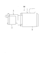
- FIG. 1 is a schematic configuration diagram of a hydraulic pump 100 in which a synchronous reluctance rotating electrical machine (hereinafter simply referred to as a rotating electrical machine) 1 is incorporated.
- the hydraulic pump 100 includes a pump unit 2 and a rotating electrical machine 1 that drives the pump unit 2.
- the pump unit 2 is a unit in which a pump body (not shown) is accommodated in a pump casing 3 having water tightness. The driving force of the rotating electrical machine 1 is transmitted to the pump body. When the pump body is driven, liquid is sucked and discharged inside and outside the pump casing 3.
- the rotating electrical machine 1 is composed of an electric motor casing 4, a stator 6 described later housed in the electric motor casing 4, and a rotor 7.
- the electric motor casing 4 and the pump casing 3 are connected via, for example, bolts or the like so as to ensure water tightness.
- the motor casing 4 is provided with a power supply box 5 for supplying current to the stator 6.
- FIG. 2 is a cross-sectional view orthogonal to the rotating shaft 12 showing a partial configuration of the rotating electrical machine 1.
- the rotating electrical machine 1 includes a substantially cylindrical stator 6, a rotor 7 provided radially inward of the stator 6, and rotatably provided with respect to the stator 6; It has. Note that the stator 6 and the rotor 7 are arranged in a state where their respective central axes are located on a common axis.
- the common axis will be referred to as a central axis (rotation axis) O
- a direction orthogonal to the central axis O will be referred to as a radial direction
- a direction that goes around the central axis O will be referred to as a circumferential direction.
- the stator 6 has a substantially cylindrical stator core 8.
- the stator core 8 can be formed by laminating a plurality of electromagnetic steel plates or by press-molding soft magnetic powder.
- a plurality of teeth 9 protruding toward the central axis O and arranged at equal intervals in the circumferential direction are integrally formed on the inner peripheral surface of the stator core 8.
- the number of teeth 9 is set to “36”.
- the teeth 9 have a substantially T-shaped cross section along the radial direction.
- a plurality of slots 10 and a plurality of teeth 9 are formed at equal intervals in the circumferential direction so that one slot 10 is arranged between adjacent teeth 9.
- the number of slots 10 is also the same as the number of teeth 9. That is, for example, in the present embodiment, the number of slots 10 is set to “36”.
- An armature winding 11 is wound around each tooth 9 through these slots 10.
- An armature winding 11 is wound on each tooth 9 from above the insulator and the insulating coating.
- the rotor 7 includes a rotary shaft 12 extending along the central axis O, and a substantially cylindrical rotor core 13 that is externally fitted and fixed to the rotary shaft 12.
- the rotor core 13 can be formed by laminating a plurality of electromagnetic steel plates or press-molding soft magnetic powder.
- the outer diameter of the rotor core 13 is set so that a predetermined air gap G is formed between the teeth 9 facing the rotor core 13 in the radial direction.
- a through hole 14 that penetrates along the central axis O is formed at the radial center of the rotor core 13.
- the rotary shaft 12 is press-fitted into the through-hole 14, and the rotary shaft 12 and the rotor core 13 rotate together.
- the rotor core 13 has four layers of cavity portions (flux barriers) 15, 16, 17, 18 (first cavity portion 15, second cavity portion 16, A third cavity portion 17 and a fourth cavity portion 18) are formed side by side in the radial direction. That is, the first cavity 15 is formed in the radially outermost side (position farthest from the rotating shaft 12), and the second cavity 16 and the third cavity are sequentially formed from the first cavity 15 toward the radially inner side. 17 and the fourth cavity 18 are formed side by side. And the 4th cavity part 18 is arrange
- each of the hollow portions 15 to 18 is formed along the flow of magnetic flux formed when the armature winding 11 is energized. That is, each of the cavities 15 to 18 is curved so that the center in the circumferential direction is located on the innermost side in the radial direction (to be convex toward the inner side in the radial direction). As a result, a direction in which the magnetic flux easily flows and a direction in which the magnetic flux does not easily flow are formed in the rotor core 13.
- each of the cavities 15 to 18 has a multilayer structure in the radial direction along the d-axis. More specifically, in the q-axis direction of the rotor core 13, the direction in which the flow of magnetic flux is not hindered by the hollow portions 15 to 18 is referred to as the q-axis.
- a positive magnetic position (for example, the N pole of the magnet is brought closer) is given to an arbitrary circumferential angle position on the outer peripheral surface 13a of the rotor core 13.
- a negative magnetic position (for example, the S pole of the magnet is brought closer) is given to any other circumferential angle position shifted by one pole (in this embodiment, 90 degrees in mechanical angle) with respect to the positive magnetic position.
- the positions of such positive magnetic potential and negative magnetic potential are shifted in the circumferential direction, the direction from the central axis O to the arbitrary position when the most magnetic flux flows is defined as the q axis. .
- the longitudinal direction of each cavity 15 to 18 is the q axis.
- the d-axis is a direction parallel to the direction in which the two rotor core parts separated by the hollow portions 15 to 18 into a region close to the central axis O and a region far from the central axis O face each other.
- the cavities 15 to 18 are formed in multiple layers (four layers in this embodiment)
- the overlapping direction of the layers is the d-axis.
- the d-axis is not limited to being electrically and magnetically orthogonal to the q-axis, and may intersect with a certain angle width (for example, about 10 degrees in mechanical angle) from the orthogonal angle.
- the rotor core 13 is configured with four poles, and four layers of cavities 15, 16, 17, and 18 are provided per pole (a circumferential angle region of 1 ⁇ 4 circumference of the rotor core 13). It will be formed.
- 1 pole means the area
- the d-axis may be referred to as the pole center C1
- the q-axis both ends in the circumferential direction of the 1 ⁇ 4 circumferential angle region
- extreme E1 that is, each of the cavities 15 to 18 is curved inward in the radial direction so that the pole center C1 is positioned at the innermost side in the radial direction.
- the hollow portions 15 to 18 are curved so that both ends in the longitudinal direction are located in the vicinity of the outer peripheral surface 13a of the rotor core 13 when viewed from the central axis O direction.
- Each of the cavities 15 to 18 is formed so that a portion closer to both ends in the longitudinal direction is along the q-axis direction, and a portion closer to the center in the longitudinal direction is orthogonal to the d-axis. Further, each of the cavities 15 to 18 is formed so that the opening area increases in order from the first cavities 15.
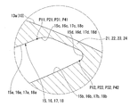
- FIG. 3 is an enlarged view of a portion A in FIG.
- bridges 21, 22, 23, and 24 are provided between the circumferential ends of each of the hollow portions 15 to 18 and the outer peripheral surface 13a of the rotor core 13.
- a third bridge 23, and a fourth bridge 24 are formed.
- the bridges 21 to 24 are those formed near the outer peripheral portion of the rotor core 13 in each of the hollow portions 15 to 18 and within a range in which the wall thickness changes rapidly.
- the wall thickness refers to the thickness along the normal direction of the outer peripheral surface 13a of the rotor core 13.
- FIG. 4 is an explanatory diagram for explaining the shapes of both end portions in the longitudinal direction of the hollow portions 15 to 18. Since the basic configuration of the shape of each end portion in the longitudinal direction of each of the cavities 15 to 18 is the same, FIG. 4 will be described with reference to 15 to 18 for one cavities.
- the cavities 15 to 18 are formed along the flow of magnetic flux formed when the armature winding 11 is energized. For this reason, the two inner side surfaces 15a, 15b, 16a, 16b, 17a, 17b, 18a, and 18b that face each other in the short direction of each of the hollow portions 15 to 18 are not formed by one curvature radius, It consists of an assembly of curves having a plurality of radii of curvature.
- each of the cavities 15 to 18 has inflection points P11, P21, P31, and P41 at connection points between the inner side surfaces 15a, 16a, 17a, and 18a and the outward curved surfaces 15c, 16c, 17c, and 18c, respectively. is doing.
- each of the cavities 15 to 18 has curvature change points P12, P22, P32, and P42 at the connection points between the inner side surfaces 15b, 16b, 17b, and 18b and the small arcuate surfaces 15d, 16d, 17d, and 18d, respectively. ing.
- Each of the bridges 21 to 24 is near the outer periphery of the rotor core 13 in each of the hollow portions 15 to 18 and includes inflection points P11, P21, P31, and P41 and curvature change points P12, P22, P32, and P42. The thick part between.
- a circumferential width (circumferential length) W2 between the second bridge 22 and the third bridge 23 is a circumferential width (circumferential length) W1 between the first bridge 21 and the second bridge 22. And it is set longer than the circumferential width (circumferential length) W3 between the third bridge 23 and the fourth bridge 24 (hereinafter referred to as condition 1). Further, since each of the cavities 15 to 18 is curved so as to have a convex shape toward the inside in the radial direction, the circumferential width W1 to W3 between the bridges 21 to 24 is set to the above condition (1 ) Is set as follows.
- the width W5 between the second cavity portion 16 and the third cavity portion 17 is the width W4 between the first cavity portion 15 and the second cavity portion, and the third cavity portion 17 and the fourth cavity portion 4. It is set longer than the width W6 between the cavity 18 (hereinafter referred to as condition 2). It should be noted that the relationship between the sizes of the widths W4 to W6 between the hollow portions 15 to 18 is set to the same size at any arbitrary location.
- the positions 24 are defined as a first reference bridge position 21K, a second reference bridge position 22K, a third reference bridge position 23K, and a fourth reference bridge position 24K, respectively.
- the first bridge 21 and the fourth bridge 24 are arranged at the same positions as the corresponding first reference bridge position 21K and fourth reference bridge position 24K, respectively.
- the second bridge 22 is disposed at a position displaced from the second reference bridge position 22K toward the first reference bridge position 21K (first bridge 21) (see arrow Y1 in FIG. 3).
- the third bridge 23 is disposed at a position displaced from the third reference bridge position 23K toward the fourth reference bridge position 24K (fourth bridge 24) (see arrow Y2 in FIG. 3).
- An angle between the third straight line L3 passing through the point P21 and the extreme E1 is ⁇ 3, and a fourth straight line L4 passing through the central axis O and the curvature change point P22 of the second bridge 22 (second cavity portion 16)
- the angle between the extreme E1 is ⁇ 4
- the angle between the extreme E1 and the fifth straight line L5 passing through the center axis O and the inflection point P31 of the third bridge 23 (third cavity portion 17) is ⁇ 5.
- the angle between the extreme E1 and the seventh straight line L7 passing through the center axis O and the inflection point P41 of the fourth bridge 24 (fourth cavity 18) is ⁇ 6.
- the interaction with the iron core 8 will be described.
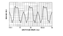
- the vertical axis indicates the ease of passing the magnetic flux of the rotor core 13
- the horizontal axis indicates the change in the ease of passing the magnetic flux of the rotor core 13 when the position of the rotor core 13 (rotation angle [deg]) is set. It is a graph which shows.
- the magnetic flux between the pole center C1 (rotation angle 0 ° position) of the rotor core 13 and the extreme E1 (rotation angle 45 ° position) is obtained. It can be confirmed that the ease of passing changes.
- the cavities 15 to 18 are formed at the positions corresponding to the bridges 21 to 24, the magnetic flux hardly passes at the positions corresponding to the bridges 21 to 24.
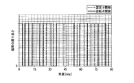
- the vertical axis indicates the ease of passing the magnetic flux of the stator core 8 and the rotor core 13
- the horizontal axis indicates the position of the stator core 8 and the rotor core 13 (rotation angle [deg]).
- the change in the ease of passing the magnetic flux is simplified to a rectangular wave.
- the portion corresponding to the slot 10 is a space, so that it is difficult for the magnetic flux to pass.
- This is a graph of the change in the magnetic flux of the stator core 8 (indicated by a broken line in FIG.
- torque ripple is generated by the interaction between the magnetic unevenness of the stator 6 and the magnetic unevenness of the rotor 7. That is, in FIG. 6, as the number of places where the ease of passing the magnetic flux becomes “0”, the number of times that the magnetic flux density rapidly changes increases, and the torque ripple tends to increase. For this reason, torque ripple can be reduced in the rotor core 13 of the present embodiment in which there are almost no places where the magnetic flux passage is “0”.
- FIG. 7 shows changes in the torque of the rotating electrical machine 1 when the vertical axis is torque and the horizontal axis is the electrical angle of the rotor 7, and the circumferential widths W1 to W3 between the bridges 21 to 24 are equally spaced. And the case where the circumferential widths W1 to W3 between the bridges 21 to 24 are set so as to satisfy the above formula (1). As shown in the figure, when the circumferential widths W1 to W3 between the bridges 21 to 24 are set so as to satisfy the above formula (1), the circumferential widths W1 to W3 between the bridges 21 to 24 are set. It can be confirmed that the change in torque (torque ripple) is reduced as compared with the case where the distances are equal.
- the circumferential widths W1 to W3 between the bridges 21 to 24 are set so as to satisfy the above condition 1. Further, the widths W4 to W6 between the hollow portions 15 to 18 are set so as to satisfy the above condition 2. For this reason, torque ripple can be reduced and the performance of the rotating electrical machine 1 can be improved without reducing the torque performance of the rotating electrical machine 1.
- the first bridge 21 and the fourth bridge 24 are respectively set to the corresponding first reference bridge position 21K and fourth reference bridge position. It is arranged at the same position as 24K.
- the second bridge 22 is disposed at a position displaced from the second reference bridge position 22K toward the first reference bridge position 21K (first bridge 21).
- the third bridge 23 is disposed at a position displaced from the third reference bridge position 23K toward the fourth reference bridge position 24K (fourth bridge 24). For this reason, torque ripple can be effectively reduced while preventing the torque of the rotating electrical machine 1 from being reduced.
- the number of teeth 9 and slots 10 of the stator core 8 is set to “36”, and the rotor core 13 is configured to have four poles, so that the rotor core 13 is per pole (1/1 of the rotor core 13).
- the circumferential widths W1 to W3 between the bridges 21 to 24 are expressed by the above equation (1).
- each of the cavities 15 to 18 may be formed so as to be substantially V-shaped or at least partially linear.
- the circumferential widths W1 to W3 between the bridges 21 to 24 are set to satisfy the above condition 1. Further, the widths W4 to W6 between the hollow portions 15 to 18 are set so as to satisfy the above condition 2. For this reason, torque ripple can be reduced and the performance of the rotating electrical machine 1 can be improved without reducing the torque performance of the rotating electrical machine 1.
- the first bridge 21 and the fourth bridge 24 are respectively set to the corresponding first reference bridge position 21K and fourth reference bridge position. It is arranged at the same position as 24K.
- the second bridge 22 is disposed at a position displaced from the second reference bridge position 22K toward the first reference bridge position 21K (first bridge 21).
- the third bridge 23 is disposed at a position displaced from the third reference bridge position 23K toward the fourth reference bridge position 24K (fourth bridge 24). For this reason, torque ripple can be effectively reduced while preventing the torque of the rotating electrical machine 1 from being reduced.
- the number of teeth 9 and slots 10 of the stator core 8 is set to “36”, and the rotor core 13 is configured to have four poles, so that the rotor core 13 is per pole (1/1 of the rotor core 13).
- the circumferential widths W1 to W3 between the bridges 21 to 24 are expressed by the above equation (1).
Abstract
実施形態の同期リラクタンス回転電機は、シャフトと、回転子鉄心と、を持つ。シャフトは、回転軸線回りに回転する。回転子鉄心は、シャフトに固定され、1極当りに径方向内側に向かって凸形状となる空洞部が4層形成されていると共に、各空洞部と外周面との間にそれぞれブリッジが形成されている。そして、1極のうち周方向中央を極中心とし、周方向両端を極端とし、複数の前記ブリッジを、前記極中心から前記極端に向かって順に1層目ブリッジ、2層目ブリッジ、3層目ブリッジ、4層目ブリッジとしたとき、2層目ブリッジと3層目ブリッジとの間の周方向の幅を、1層目ブリッジと2層目ブリッジとの間の周方向の幅、および3層目ブリッジと4層目ブリッジとの間の周方向の幅よりも広く設定した。
Description
本発明の実施形態は、同期リラクタンス回転電機に関する。
同期リラクタンス型回転電機は、回転子と、固定子と、を備えている。回転子は、回転可能に軸支されて回転軸中心で軸方向に延びるシャフトと、シャフトに外嵌固定される回転子鉄心と、を備えている。固定子は、回転子鉄心の外周に、この回転子鉄心と間隔をあけて配置されている。固定子は、互いに周方向に間隔をあけて配列された複数のティースを有する固定子鉄心と、複数のティースにそれぞれ巻回された複数極の多相の電機子巻線と、を備えている。
回転子鉄心には、1極当り複数の空洞部が径方向に並んで形成されている。各空洞部は、電機子巻線に通電した際に形成される磁束の流れに沿うように、極中心が最も径方向内側に位置するように、径方向内側に向かって湾曲形成されている場合が多い。
このように空洞部を形成することにより、回転子鉄心に、磁束の流れ易い方向と磁束の流れにくい方向とが形成される。このような構成のもと、同期リラクタンス型回転電機は、空洞部によって発生するリラクタンストルクを利用し、シャフトを回転させる。
このように空洞部を形成することにより、回転子鉄心に、磁束の流れ易い方向と磁束の流れにくい方向とが形成される。このような構成のもと、同期リラクタンス型回転電機は、空洞部によって発生するリラクタンストルクを利用し、シャフトを回転させる。
ところで、固定子鉄心の各ティース間に形成されるスロットは、磁束が流れにくい箇所である。このため、ティースとスロットとの間で磁束密度が急激に変化する(以下、この磁束密度の急激な変化を固定子の磁気的凹凸という)。一方、回転子鉄心も、リラクタンストルクを発生させるべく形成した空洞部によって、磁束密度が急激に変化する箇所が複数個所形成される(以下、この磁束密度の急激な変化を回転子の磁気的凹凸という)。そして、これら固定子の磁気的凹凸と回転子の磁気的凹凸との相互作用によって、トルクリップルが発生する。また、トルクリップルは、固定子鉄心の磁気的凹凸と回転子鉄心の磁気的凹凸とが共振すると大きくなってしまう可能性があった。
本発明が解決しようとする課題は、トルクリップルを低減できる同期リラクタンス回転電機を提供することである。
実施形態の同期リラクタンス回転電機は、シャフトと、回転子鉄心と、を持つ。シャフトは、回転軸線回りに回転する。回転子鉄心は、シャフトに固定され、1極当りに径方向内側に向かって凸形状となる空洞部が4層形成されていると共に、各空洞部と外周面との間にそれぞれブリッジが形成されている。そして、1極のうち周方向中央を極中心とし、周方向両端を極端とし、複数の前記ブリッジを、前記極中心から前記極端に向かって順に1層目ブリッジ、2層目ブリッジ、3層目ブリッジ、4層目ブリッジとしたとき、2層目ブリッジと3層目ブリッジとの間の周方向の幅を、1層目ブリッジと2層目ブリッジとの間の周方向の幅、および3層目ブリッジと4層目ブリッジとの間の周方向の幅よりも広く設定した。
以下、実施形態の同期リラクタンス回転電機を、図面を参照して説明する。
図1は、同期リラクタンス回転電機(以下、単に回転電機という)1が組み込まれた液圧ポンプ100の概略構成図である。
同図に示すように、液圧ポンプ100は、ポンプ部2とポンプ部2を駆動する回転電機1と、により構成されている。ポンプ部2は、水密性を有するポンプケーシング3内に不図示のポンプ本体を収納したものである。このポンプ本体に、回転電機1の駆動力が伝達される。ポンプ本体が駆動することにより、ポンプケーシング3内外に液体が吸入吐出される。
同図に示すように、液圧ポンプ100は、ポンプ部2とポンプ部2を駆動する回転電機1と、により構成されている。ポンプ部2は、水密性を有するポンプケーシング3内に不図示のポンプ本体を収納したものである。このポンプ本体に、回転電機1の駆動力が伝達される。ポンプ本体が駆動することにより、ポンプケーシング3内外に液体が吸入吐出される。
一方、回転電機1は、電動機ケーシング4と、電動機ケーシング4内に収納された後述の固定子6、および回転子7と、により構成されている。電動機ケーシング4とポンプケーシング3は、互いに水密性を確保可能なように、例えばボルト等を介して連結されている。電動機ケーシング4には、固定子6に電流を供給するための給電ボックス5が設けられている。
図2は、回転電機1の一部の構成を示す回転軸12に直交する断面図である。なお、図2では、回転電機1の1/4セクター、すなわち、1/4周の周角度領域分のみを示している。
同図に示すように、回転電機1は、略円筒状の固定子6と、固定子6よりも径方向内側に設けられ、固定子6に対して回転自在に設けられた回転子7と、を備えている。なお、固定子6および回転子7は、それぞれの中心軸線が共通軸上に位置した状態で配置されている。以下、共通軸を中心軸(回転軸線)Oと称し、中心軸Oに直交する方向を径方向と称し、中心軸O回りに周回する方向を周方向と称して説明する。
同図に示すように、回転電機1は、略円筒状の固定子6と、固定子6よりも径方向内側に設けられ、固定子6に対して回転自在に設けられた回転子7と、を備えている。なお、固定子6および回転子7は、それぞれの中心軸線が共通軸上に位置した状態で配置されている。以下、共通軸を中心軸(回転軸線)Oと称し、中心軸Oに直交する方向を径方向と称し、中心軸O回りに周回する方向を周方向と称して説明する。
固定子6は、略円筒状の固定子鉄心8を有している。固定子鉄心8は、電磁鋼板を複数枚積層したり、軟磁性粉を加圧成形したりして形成することが可能である。固定子鉄心8の内周面には、中心軸Oに向かって突出し、周方向に等間隔で配列された複数のティース9が一体成形されている。例えば本実施形態では、ティース9の数は、「36」に設定されている。
ティース9は、径方向に沿う断面が略T字状に形成されている。そして、隣接するティース9間に1つのスロット10が配置するように、複数のスロット10及び複数のティース9が周方向に等間隔で形成されている。スロット10の数も、ティース9の数と同数になる。すなわち、例えば本実施形態では、スロット10の数は、「36」に設定される。
そして、これらスロット10を介し、各ティース9に電機子巻線11が巻回されている。各ティース9には、インシュレータや絶縁被膜の上から電機子巻線11が巻回される。
そして、これらスロット10を介し、各ティース9に電機子巻線11が巻回されている。各ティース9には、インシュレータや絶縁被膜の上から電機子巻線11が巻回される。
回転子7は、中心軸Oに沿って延びる回転軸12と、回転軸12に外嵌固定された略円柱状の回転子鉄心13と、を備えている。
回転子鉄心13は、電磁鋼板を複数枚積層したり、軟磁性粉を加圧成形したりして形成することが可能である。回転子鉄心13の外径は、回転子鉄心13と径方向で対向する各ティース9との間に、所定のエアギャップGが形成されるように設定されている。
また、回転子鉄心13の径方向中央には、中心軸Oに沿って貫通する貫通孔14が形成されている。この貫通孔14に、回転軸12が圧入等され、回転軸12と回転子鉄心13とが一体となって回転する。
回転子鉄心13は、電磁鋼板を複数枚積層したり、軟磁性粉を加圧成形したりして形成することが可能である。回転子鉄心13の外径は、回転子鉄心13と径方向で対向する各ティース9との間に、所定のエアギャップGが形成されるように設定されている。
また、回転子鉄心13の径方向中央には、中心軸Oに沿って貫通する貫通孔14が形成されている。この貫通孔14に、回転軸12が圧入等され、回転軸12と回転子鉄心13とが一体となって回転する。
さらに、回転子鉄心13には、1/4周の周角度領域のそれぞれに、4層の空洞部(フラックスバリア)15,16,17,18(第1空洞部15、第2空洞部16、第3空洞部17、第4空洞部18)が径方向に並んで形成されている。すなわち、径方向最外側(回転軸12から最も離れた位置)に第1空洞部15が形成され、この第1空洞部15から径方向内側に向かって順に第2空洞部16、第3空洞部17、第4空洞部18が並んで形成されている。そして、第4空洞部18が径方向最内側(回転軸12に最も近い位置)に配置されている。
また、各空洞部15~18は、電機子巻線11に通電した際に形成される磁束の流れに沿うように形成されている。つまり、各空洞部15~18は、周方向の中央が最も径方向内側に位置するように(径方向内側に向かって凸形状となるように)、湾曲形成されている。これにより、回転子鉄心13には、磁束の流れ易い方向と磁束の流れにくい方向が形成される。
ここで、本実施形態において、磁束の流れ易い方向をq軸と称する。また、q軸に対して電気的、磁気的に直交する径方向に沿った方向をd軸と称する。すなわち、各空洞部15~18は、d軸に沿った径方向において、多層構造となる。
より詳しくは、回転子鉄心13においてq軸方向は、各空洞部15~18によって磁束の流れが妨げられない方向をq軸と称する。すなわち、回転子鉄心13の外周面13aの任意の周角度位置に正の磁位(例えば磁石のN極を近づける)を与える。また、正の磁位に対して1極分(本実施形態の場合は機械角で90度)ずれた他の任意の周角度位置に負の磁位(例えば磁石のS極を近づける)を与える。そして、このような正の磁位及び負の磁位の位置を周方向へずらしていった場合に最も多くの磁束が流れる時の中心軸Oから任意の位置に向かう方向をq軸と定義する。そして、各空洞部15~18の長手方向がq軸である。
より詳しくは、回転子鉄心13においてq軸方向は、各空洞部15~18によって磁束の流れが妨げられない方向をq軸と称する。すなわち、回転子鉄心13の外周面13aの任意の周角度位置に正の磁位(例えば磁石のN極を近づける)を与える。また、正の磁位に対して1極分(本実施形態の場合は機械角で90度)ずれた他の任意の周角度位置に負の磁位(例えば磁石のS極を近づける)を与える。そして、このような正の磁位及び負の磁位の位置を周方向へずらしていった場合に最も多くの磁束が流れる時の中心軸Oから任意の位置に向かう方向をq軸と定義する。そして、各空洞部15~18の長手方向がq軸である。
一方、各空洞部15~18によって磁束の流れが妨げられる方向、すなわちq軸に対して磁気的に直交する方向をd軸と称する。本実施形態では、各空洞部15~18によって、中心軸Oに近い領域と遠い領域に分離された2つの回転子鉄心部分が対向する方向に対して平行な方向がd軸である。また、各空洞部15~18が多層に形成されている場合(本実施形態では4層)、層の重なり方向がd軸である。本実施形態では、d軸は、q軸に対して電気的、磁気的に直交するのに限らず、直交する角度からある程度の角度幅(例えば機械角で10度程度)をもって交わってよい。
このように、回転子鉄心13は、4極に構成されており、1極当り(回転子鉄心13の1/4周の周角度領域)に4層の空洞部15,16,17,18が形成されていることになる。そして、1極とは、q軸間の領域をいう。
なお、以下の説明では、d軸を極中心C1と称し、q軸(1/4周の周角度領域の周方向両端)を極端E1と称して説明する場合がある。つまり、各空洞部15~18は、極中心C1が最も径方向内側に位置するように、径方向内側に向かって湾曲されていることになる。
なお、以下の説明では、d軸を極中心C1と称し、q軸(1/4周の周角度領域の周方向両端)を極端E1と称して説明する場合がある。つまり、各空洞部15~18は、極中心C1が最も径方向内側に位置するように、径方向内側に向かって湾曲されていることになる。
また、各空洞部15~18は、中心軸O方向からみて長手方向両端が回転子鉄心13の外周面13a近傍に位置するように湾曲形成されている。そして、各空洞部15~18は、長手方向両端に近い箇所ほどq軸方向に沿うように、且つ長手方向中央に近い箇所ほどd軸と直交するように形成されている。さらに、各空洞部15~18は、第1空洞部15から順に開口面積が大きくなるように形成されている。
図3は、図2のA部拡大図である。
同図に示すように、各空洞部15~18の周方向両端と回転子鉄心13の外周面13aとの間には、それぞれブリッジ21,22,23,24(第1ブリッジ21、第2ブリッジ22、第3ブリッジ23、第4ブリッジ24)が形成されている。詳述すると、ブリッジ21~24とは、各空洞部15~18における回転子鉄心13の外周部寄りで、且つその肉厚が急激に変化する範囲に形成されているものをいう。なお、肉厚とは、回転子鉄心13の外周面13aの法線方向に沿った厚さのことをいう。
同図に示すように、各空洞部15~18の周方向両端と回転子鉄心13の外周面13aとの間には、それぞれブリッジ21,22,23,24(第1ブリッジ21、第2ブリッジ22、第3ブリッジ23、第4ブリッジ24)が形成されている。詳述すると、ブリッジ21~24とは、各空洞部15~18における回転子鉄心13の外周部寄りで、且つその肉厚が急激に変化する範囲に形成されているものをいう。なお、肉厚とは、回転子鉄心13の外周面13aの法線方向に沿った厚さのことをいう。
さらに、ブリッジ21~24について、以下に詳述する。
ブリッジ21~24を詳述するにあたって、まず、図3、図4に基づいて、各空洞部15~18の長手方向両端の形状について詳述する。
図4は、各空洞部15~18の長手方向両端部の形状を説明するための説明図である。
なお、各空洞部15~18の長手方向両端部の形状の基本的構成は同一であるので、図4では、1つの空洞部に符号15~18を付して説明する。
ブリッジ21~24を詳述するにあたって、まず、図3、図4に基づいて、各空洞部15~18の長手方向両端の形状について詳述する。
図4は、各空洞部15~18の長手方向両端部の形状を説明するための説明図である。
なお、各空洞部15~18の長手方向両端部の形状の基本的構成は同一であるので、図4では、1つの空洞部に符号15~18を付して説明する。
図3、図4に示すように、各空洞部15~18は、電機子巻線11に通電した際に形成される磁束の流れに沿うように形成されている。このため、各空洞部15~18の短手方向で対向する2つの内側面15a,15b,16a,16b,17a,17b,18a,18bは、1つの曲率半径によって形成されているのではなく、複数の曲率半径を有する曲線の集合体からなる。
ここで、各空洞部15~18の内側面15a~18bは、中央の大部分が径方向内側に向かって凸形状となるように湾曲形成されているが、各空洞部15~18の内側面15a~18bのうち、回転軸12側とは反対側の内側面15a,16a,17a,18aの長手方向両端には、径方向外側に向かって凸形状となるように湾曲形成された外向き湾曲面15c,16c,17c,18cが形成されている。すなわち、各空洞部15~18は、内側面15a,16a,17a,18aと外向き湾曲面15c,16c,17c,18cとの接続箇所に、それぞれ変曲点P11,P21,P31,P41が存在している。
一方、各空洞部15~18の内側面15a~18bのうち、回転軸12側の内側面15b,16b,17b,18bの長手方向両端には、曲率半径が急激に小さくなる小弧状面15d,16d,17d,18dが形成されている。すなわち、各空洞部15~18は、内側面15b,16b,17b,18bと小弧状面15d,16d,17d,18dとの接続箇所に、それぞれ曲率変化点P12、P22,P32,P42が存在している。
そして、各ブリッジ21~24は、各空洞部15~18における回転子鉄心13の外周部寄りで、且つ変曲点P11,P21,P31,P41と曲率変化点P12,P22,P32,P42との間の肉厚部分をいう。
そして、各ブリッジ21~24は、各空洞部15~18における回転子鉄心13の外周部寄りで、且つ変曲点P11,P21,P31,P41と曲率変化点P12,P22,P32,P42との間の肉厚部分をいう。
ここで、
(1)第2ブリッジ22と第3ブリッジ23との間の周方向の幅(周長)W2は、第1ブリッジ21と第2ブリッジ22との間の周方向の幅(周長)W1、および第3ブリッジ23と第4ブリッジ24との間の周方向の幅(周長)W3よりも長く設定されている(以下、条件1という)。
また、各空洞部15~18が何れも径方向内側に向かって凸形状となるように湾曲形成されていることから、各ブリッジ21~24間の周方向の幅W1~W3を上記条件(1)のように設定することにより、以下のように設定される。
(2)すなわち、第2空洞部16と第3空洞部17との間の幅W5は、第1空洞部15と第2空洞部との間の幅W4、および第3空洞部17と第4空洞部18との間の幅W6よりも長く設定されている(以下、条件2という)。なお、各空洞部15~18間の幅W4~W6の大きさの関係は、任意の何れの箇所も同様の大きさの関係に設定されている。
ここで、上記条件(1)、条件(2)のように各幅W1~W6を設定するための具体的な各空洞部15~18の形成位置について説明する。
すなわち、図3に二点鎖線で示すように、各ブリッジ21~24間の周方向の幅W1~W3がそれぞれ等間隔になるように各空洞部15~18を配置した場合の各ブリッジ21~24の位置を、それぞれ第1基準ブリッジ位置21K、第2基準ブリッジ位置22K、第3基準ブリッジ位置23K、および第4基準ブリッジ位置24Kとする。そして、第1ブリッジ21および第4ブリッジ24は、それぞれ対応する第1基準ブリッジ位置21Kおよび第4基準ブリッジ位置24Kと同一位置に配置される。
すなわち、図3に二点鎖線で示すように、各ブリッジ21~24間の周方向の幅W1~W3がそれぞれ等間隔になるように各空洞部15~18を配置した場合の各ブリッジ21~24の位置を、それぞれ第1基準ブリッジ位置21K、第2基準ブリッジ位置22K、第3基準ブリッジ位置23K、および第4基準ブリッジ位置24Kとする。そして、第1ブリッジ21および第4ブリッジ24は、それぞれ対応する第1基準ブリッジ位置21Kおよび第4基準ブリッジ位置24Kと同一位置に配置される。
これに対し、第2ブリッジ22は、第2基準ブリッジ位置22Kから第1基準ブリッジ位置21K(第1ブリッジ21)寄りに変位(図3における矢印Y1参照)させた位置に配置される。また、第3ブリッジ23は、第3基準ブリッジ位置23Kから第4基準ブリッジ位置24K(第4ブリッジ24)寄りに変位(図3における矢印Y2参照)させた位置に配置される。
これにより、各ブリッジ21~24間の周方向の幅W1~W3を、上記条件(1)のように設定することができる。この結果、各空洞部15~18間の幅W4~W6を、上記条件(2)のように設定することができる。
これにより、各ブリッジ21~24間の周方向の幅W1~W3を、上記条件(1)のように設定することができる。この結果、各空洞部15~18間の幅W4~W6を、上記条件(2)のように設定することができる。
このような条件(1)を満たす場合の最適値について、以下に説明する。
すなわち、中心軸Oと第1ブリッジ21(第1空洞部15)の変曲点P11とを通る第1直線L1と、極端E1との間の角度をθ1とし、中心軸Oと第1ブリッジ21(第1空洞部15)の曲率変化点P12とを通る第2直線L2と、極端E1との間の角度をθ2とし、中心軸Oと第2ブリッジ22(第2空洞部16)の変曲点P21とを通る第3直線L3と、極端E1との間の角度をθ3とし、中心軸Oと第2ブリッジ22(第2空洞部16)の曲率変化点P22とを通る第4直線L4と、極端E1との間の角度をθ4とし、中心軸Oと第3ブリッジ23(第3空洞部17)の変曲点P31とを通る第5直線L5と、極端E1との間の角度をθ5とし、中心軸Oと第3ブリッジ23(第3空洞部17)の曲率変化点P32とを通る第6直線L6と、極端E1との間の角度をθ6とし、中心軸Oと第4ブリッジ24(第4空洞部18)の変曲点P41とを通る第7直線L7と、極端E1との間の角度をθ7とし、中心軸Oと第4ブリッジ24(第4空洞部18)の曲率変化点P42とを通る第8直線L8と、極端E1との間の角度をθ8としたとき、角度θ1~θ8は、それぞれ
θ1=3.2°、θ2=5.5°、θ3=9.4°、θ4=12.8°、θ5=20°、θ6=23.3°、θ7=31°、θ8=36.6°・・・(1)
を満たすように設定されている。
次に、図5、図6に基づいて、上記式(1)のように角度θ1~θ8を設定した回転子鉄心13と、ティース9およびスロット10の数が「36」に設定された固定子鉄心8との相互作用について説明する。
図5は、縦軸を回転子鉄心13の磁束の通り易さとし、横軸を回転子鉄心13の位置(回転角[deg])とした場合の回転子鉄心13の磁束の通り易さの変化を示すグラフである。
同図に示すように、各空洞部15~18を形成することにより、回転子鉄心13の極中心C1(回転角0°位置)から極端E1(回転角45°位置)に至る間に、磁束の通り易さが変化することが確認できる。ここで、各ブリッジ21~24に対応する位置にそれぞれ空洞部15~18が形成されているので、各ブリッジ21~24に対応する位置では、磁束が通りにくくなる。
図5は、縦軸を回転子鉄心13の磁束の通り易さとし、横軸を回転子鉄心13の位置(回転角[deg])とした場合の回転子鉄心13の磁束の通り易さの変化を示すグラフである。
同図に示すように、各空洞部15~18を形成することにより、回転子鉄心13の極中心C1(回転角0°位置)から極端E1(回転角45°位置)に至る間に、磁束の通り易さが変化することが確認できる。ここで、各ブリッジ21~24に対応する位置にそれぞれ空洞部15~18が形成されているので、各ブリッジ21~24に対応する位置では、磁束が通りにくくなる。
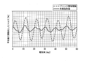
図6は、縦軸を固定子鉄心8および回転子鉄心13の磁束の通り易さとし、横軸を固定子鉄心8および回転子鉄心13の位置(回転角[deg])とした場合の固定子鉄心8および回転子鉄心13の磁束の通り易さの変化を比較したグラフである。なお、図6では、説明を分かり易くするために、磁束の通り易さの変化を矩形波に簡素化して示している。
同図に示すように、固定子鉄心8では、スロット10に対応する箇所が空間となるため、磁束が通りにくくなる。これを固定子鉄心8の磁束の通り易さの変化のグラフ(図6中、破線で示す)と、回転子鉄心13の磁束の通り易さの変化のグラフ(図6中実線で示す)とを重ね合わせて比較すると、磁束の通りにくい箇所、つまり、磁束の通り易さが「0」となる箇所が、殆ど存在しないことが確認できる。
同図に示すように、固定子鉄心8では、スロット10に対応する箇所が空間となるため、磁束が通りにくくなる。これを固定子鉄心8の磁束の通り易さの変化のグラフ(図6中、破線で示す)と、回転子鉄心13の磁束の通り易さの変化のグラフ(図6中実線で示す)とを重ね合わせて比較すると、磁束の通りにくい箇所、つまり、磁束の通り易さが「0」となる箇所が、殆ど存在しないことが確認できる。
ここで、前述したように、固定子6の磁気的凹凸と回転子7の磁気的凹凸との相互作用によって、トルクリップルが発生する。すなわち、図6中、磁束の通り易さが「0」となる箇所が多ければ多いほど、磁束密度の急激な変化が起きる回数が増えることになり、トルクリップルが大きくなりやすい。このため、磁束の通り易さが「0」となる箇所が、殆ど存在しない本実施形態の回転子鉄心13では、トルクリップルを低減できる。
図7は、縦軸をトルクとし、横軸を回転子7の電気角としたときの回転電機1のトルクの変化を示し、各ブリッジ21~24間の周方向の幅W1~W3を等間隔とした場合と、各ブリッジ21~24間の周方向の幅W1~W3を、上記式(1)を満たすように設定した場合と、を比較している。
同図に示すように、各ブリッジ21~24間の周方向の幅W1~W3を、上記式(1)を満たすように設定した場合、各ブリッジ21~24間の周方向の幅W1~W3を等間隔とした場合と比較してトルクの変化(トルクリップル)が低減されていることが確認できる。
同図に示すように、各ブリッジ21~24間の周方向の幅W1~W3を、上記式(1)を満たすように設定した場合、各ブリッジ21~24間の周方向の幅W1~W3を等間隔とした場合と比較してトルクの変化(トルクリップル)が低減されていることが確認できる。
このように、上述の実施形態では、各ブリッジ21~24間の周方向の幅W1~W3を、上記条件1を満たすように設定している。また、各空洞部15~18間の幅W4~W6を、上記条件2を満たすように設定している。このため、回転電機1のトルク性能を低下させることなく、トルクリップルを低減でき、回転電機1の性能を向上できる。
そして、各幅W1~W6を、上記条件(1)、条件(2)を満たすために、第1ブリッジ21および第4ブリッジ24を、それぞれ対応する第1基準ブリッジ位置21Kおよび第4基準ブリッジ位置24Kと同一位置に配置している。これに対し、第2ブリッジ22を、第2基準ブリッジ位置22Kから第1基準ブリッジ位置21K(第1ブリッジ21)寄りに変位させた位置に配置している。さらに、第3ブリッジ23を、第3基準ブリッジ位置23Kから第4基準ブリッジ位置24K(第4ブリッジ24)寄りに変位させた位置に配置している。このため、回転電機1のトルクが低減してしまうことを防止しつつ、トルクリップルを効果的に低減できる。
また、固定子鉄心8のティース9およびスロット10の数を「36」に設定すると共に、回転子鉄心13を4極に構成し、回転子鉄心13の1極当り(回転子鉄心13の1/4周の周角度領域)に4層の空洞部15,16,17,18を形成した回転電機1において、各ブリッジ21~24間の周方向の幅W1~W3を、上記式(1)を満たすように設定することにより、トルクリップルを最も効果的に低減できる。
なお、上述の実施形態では、回転子鉄心13の各空洞部15~18は、極中心C1が最も径方向内側に位置するように、径方向内側に向かって湾曲されている場合について説明した。しかしながら、これに限られるものではなく、各空洞部15~18がq軸方向に沿っていればよい。例えば、中心軸O方向からみて、各空洞部15~18が略V字状や少なくとも一部が直線状となるように形成されていてもよい。
また、上述の実施形態では、回転電機1にポンプ部2を連結し、液圧ポンプ100とした場合について説明した。しかしながら、これに限られるものではなく、回転電機1をさまざまな用途に使用することが可能である。
以上説明した少なくともひとつの実施形態によれば、各ブリッジ21~24間の周方向の幅W1~W3を、上記条件1を満たすように設定している。また、各空洞部15~18間の幅W4~W6を、上記条件2を満たすように設定している。このため、回転電機1のトルク性能を低下させることなく、トルクリップルを低減でき、回転電機1の性能を向上できる。
そして、各幅W1~W6を、上記条件(1)、条件(2)を満たすために、第1ブリッジ21および第4ブリッジ24を、それぞれ対応する第1基準ブリッジ位置21Kおよび第4基準ブリッジ位置24Kと同一位置に配置している。これに対し、第2ブリッジ22を、第2基準ブリッジ位置22Kから第1基準ブリッジ位置21K(第1ブリッジ21)寄りに変位させた位置に配置している。さらに、第3ブリッジ23を、第3基準ブリッジ位置23Kから第4基準ブリッジ位置24K(第4ブリッジ24)寄りに変位させた位置に配置している。このため、回転電機1のトルクが低減してしまうことを防止しつつ、トルクリップルを効果的に低減できる。
また、固定子鉄心8のティース9およびスロット10の数を「36」に設定すると共に、回転子鉄心13を4極に構成し、回転子鉄心13の1極当り(回転子鉄心13の1/4周の周角度領域)に4層の空洞部15,16,17,18を形成した回転電機1において、各ブリッジ21~24間の周方向の幅W1~W3を、上記式(1)を満たすように設定することにより、トルクリップルを最も効果的に低減できる。
本発明のいくつかの実施形態を説明したが、これらの実施形態は、例として提示したものであり、発明の範囲を限定することは意図していない。これら実施形態は、その他の様々な形態で実施されることが可能であり、発明の要旨を逸脱しない範囲で、種々の省略、置き換え、変更を行うことができる。これら実施形態やその変形は、発明の範囲や要旨に含まれると同様に、特許請求の範囲に記載された発明とその均等の範囲に含まれるものである。
Claims (4)
- 回転軸線回りに回転するシャフトと、
前記シャフトに固定され、1極当りに径方向内側に向かって凸形状となる空洞部が4層形成されていると共に、各前記空洞部と外周面との間にそれぞれブリッジが形成された回転子鉄心と、
を備え、
1極のうち周方向中央を極中心とし、周方向両端を極端とし、複数の前記ブリッジを、前記極中心から前記極端に向かって順に1層目ブリッジ、2層目ブリッジ、3層目ブリッジ、4層目ブリッジとしたとき、
前記2層目ブリッジと前記3層目ブリッジとの間の周方向の幅を、前記1層目ブリッジと前記2層目ブリッジとの間の周方向の幅、および前記3層目ブリッジと前記4層目ブリッジとの間の周方向の幅よりも広く設定した
同期リラクタンス回転電機。 - 4層の前記空洞部を、前記シャフトから最も離れた前記空洞部から前記シャフトに向かって順に1層目空洞部、2層目空洞部、3層目空洞部、4層目空洞部としたとき、
前記2層目空洞部と前記3層目空洞部との間の幅を、前記1層目空洞部と前記2層目空洞部との間の幅、および前記3層目空洞部と前記4層目空洞部との間の幅よりも広く設定した
請求項1に記載の同期リラクタンス回転電機。 - 前記1層目ブリッジと前記2層目ブリッジとの間の周方向の幅、前記2層目ブリッジと前記3層目ブリッジとの間の周方向の幅、および前記3層目ブリッジと前記4層目ブリッジとの間の周方向の幅をそれぞれ等間隔としたときの前記1層目ブリッジ、前記2層目ブリッジ、前記3層目ブリッジ、および前記4層目ブリッジの位置を、それぞれ第1基準ブリッジ位置、第2基準ブリッジ位置、第3基準ブリッジ位置、および第4基準ブリッジ位置としたとき、
前記第1基準ブリッジ位置に前記1層目ブリッジを形成し、
前記第4基準ブリッジ位置に前記4層目ブリッジを形成し、
前記第2基準ブリッジ位置から前記第1基準ブリッジ位置寄りに変位させた位置に前記2層目ブリッジを形成し、
前記第3基準ブリッジ位置から前記第4基準ブリッジ位置寄りに変位させた位置に前記3層目ブリッジを形成した
請求項1または請求項2に記載の同期リラクタンス回転電機。 - 前記回転子鉄心の周囲を取り囲むように筒状に形成され、且つ巻線が挿通されるスロットを36個有する固定子鉄心を備え、
各前記空洞部の前記ブリッジ側の縁部は、前記外周面に向かうに従って径方向内側に向かって凸となる曲線から径方向外側に向かって凸となる曲線へと変化する変曲点と、曲率半径の大きさが急激に変化する曲率変化点と、を有し、
前記回転軸線と前記1層目ブリッジの前記変曲点とを通る第1直線と、前記極端と、の間の角度をθ1とし、
前記回転軸線と前記1層目ブリッジの前記曲率変化点とを通る第2直線と、前記極端と、の間の角度をθ2とし、
前記回転軸線と前記2層目ブリッジの前記変曲点とを通る第3直線と、前記極端と、の間の角度をθ3とし、
前記回転軸線と前記2層目ブリッジの前記曲率変化点とを通る第4直線と、前記極端と、の間の角度をθ4とし、
前記回転軸線と前記3層目ブリッジの前記変曲点とを通る第5直線と、前記極端と、の間の角度をθ5とし、
前記回転軸線と前記3層目ブリッジの前記曲率変化点とを通る第6直線と、前記極端と、の間の角度をθ6とし、
前記回転軸線と前記4層目ブリッジの前記変曲点とを通る第7直線と、前記極端と、の間の角度をθ7とし、
前記回転軸線と前記4層目ブリッジの前記曲率変化点とを通る第8直線と、前記極端と、の間の角度をθ8としたとき、各前記角度は、
θ1=3.2°
θ2=5.5°
θ3=9.4°
θ4=12.8°
θ5=20°
θ6=23.3°
θ7=31°
θ8=36.6°
を満たすように設定されている
請求項1~請求項3の何れか1項に記載の同期リラクタンス回転電機。
Priority Applications (2)
| Application Number | Priority Date | Filing Date | Title |
|---|---|---|---|
| CN201780069408.6A CN109964393B (zh) | 2016-11-11 | 2017-10-20 | 同步磁阻旋转电机 |
| US16/387,583 US10554081B2 (en) | 2016-11-11 | 2019-04-18 | Synchronous reluctance rotary electric machine |
Applications Claiming Priority (2)
| Application Number | Priority Date | Filing Date | Title |
|---|---|---|---|
| JP2016-220518 | 2016-11-11 | ||
| JP2016220518A JP6718797B2 (ja) | 2016-11-11 | 2016-11-11 | 同期リラクタンス回転電機 |
Related Child Applications (1)
| Application Number | Title | Priority Date | Filing Date |
|---|---|---|---|
| US16/387,583 Continuation US10554081B2 (en) | 2016-11-11 | 2019-04-18 | Synchronous reluctance rotary electric machine |
Publications (1)
| Publication Number | Publication Date |
|---|---|
| WO2018088175A1 true WO2018088175A1 (ja) | 2018-05-17 |
Family
ID=62110000
Family Applications (1)
| Application Number | Title | Priority Date | Filing Date |
|---|---|---|---|
| PCT/JP2017/038031 WO2018088175A1 (ja) | 2016-11-11 | 2017-10-20 | 同期リラクタンス回転電機 |
Country Status (4)
| Country | Link |
|---|---|
| US (1) | US10554081B2 (ja) |
| JP (1) | JP6718797B2 (ja) |
| CN (1) | CN109964393B (ja) |
| WO (1) | WO2018088175A1 (ja) |
Families Citing this family (3)
| Publication number | Priority date | Publication date | Assignee | Title |
|---|---|---|---|---|
| EP3560073A1 (en) * | 2016-12-21 | 2019-10-30 | ABB Schweiz AG | Rotor for rotating electric machines |
| CN110581626B (zh) * | 2019-10-16 | 2022-06-10 | 南京理工大学 | 一种连续矢量控制的高速同步磁阻电机系统 |
| CN113098170B (zh) * | 2021-03-31 | 2022-07-12 | 合肥工业大学 | 一种基于田口方法的内置式永磁电机气隙磁场的优化方法 |
Citations (4)
| Publication number | Priority date | Publication date | Assignee | Title |
|---|---|---|---|---|
| JPH11262205A (ja) * | 1998-03-12 | 1999-09-24 | Fujitsu General Ltd | 永久磁石電動機 |
| JP2005198487A (ja) * | 2003-12-30 | 2005-07-21 | Hyundai Motor Co Ltd | 多層埋込型永久磁石モータのロータ構造 |
| US20090224624A1 (en) * | 2008-03-06 | 2009-09-10 | Ajith Kuttannair Kumar | Rotor structure for interior permanent magnet electromotive machine |
| JP2013225997A (ja) * | 2012-04-23 | 2013-10-31 | Hitachi Automotive Systems Ltd | 永久磁石回転電機及びそれを用いた電動車両 |
Family Cites Families (9)
| Publication number | Priority date | Publication date | Assignee | Title |
|---|---|---|---|---|
| JPS5866074A (ja) | 1981-10-15 | 1983-04-20 | Nec Corp | レ−ダ−方式 |
| ITPD20090140A1 (it) * | 2009-05-15 | 2010-11-16 | Reel S R L Unipersonale | Gruppo refrigerante |
| KR20130028142A (ko) * | 2010-07-02 | 2013-03-18 | 에이비비 리써치 리미티드 | 스포크 개구부를 구비하는 로터 디스크 |
| CN102801236A (zh) * | 2012-03-05 | 2012-11-28 | 珠海格力节能环保制冷技术研究中心有限公司 | 永磁辅助同步磁阻电机及其转子以及该电机的组装方法 |
| PL2744076T3 (pl) * | 2012-12-14 | 2017-07-31 | Abb Schweiz Ag | Wirnik do maszyny elektrycznej, maszyna elektryczna i sposób wytwarzania maszyny elektrycznej |
| JP5969946B2 (ja) | 2013-03-28 | 2016-08-17 | 東芝三菱電機産業システム株式会社 | 同期リラクタンスモータ |
| CN105830308B (zh) * | 2014-01-08 | 2018-06-29 | 三菱电机株式会社 | 旋转电机 |
| DE112014006430T5 (de) | 2014-03-05 | 2016-12-08 | Mitsubishi Electric Corporation | Synchron-Reluktanzmotor |
| EP2961039B1 (de) * | 2014-06-23 | 2019-10-02 | Siemens Aktiengesellschaft | Mechanisch stabilisierter Rotor für einen Reluktanzmotor |
-
2016
- 2016-11-11 JP JP2016220518A patent/JP6718797B2/ja active Active
-
2017
- 2017-10-20 CN CN201780069408.6A patent/CN109964393B/zh active Active
- 2017-10-20 WO PCT/JP2017/038031 patent/WO2018088175A1/ja active Application Filing
-
2019
- 2019-04-18 US US16/387,583 patent/US10554081B2/en active Active
Patent Citations (4)
| Publication number | Priority date | Publication date | Assignee | Title |
|---|---|---|---|---|
| JPH11262205A (ja) * | 1998-03-12 | 1999-09-24 | Fujitsu General Ltd | 永久磁石電動機 |
| JP2005198487A (ja) * | 2003-12-30 | 2005-07-21 | Hyundai Motor Co Ltd | 多層埋込型永久磁石モータのロータ構造 |
| US20090224624A1 (en) * | 2008-03-06 | 2009-09-10 | Ajith Kuttannair Kumar | Rotor structure for interior permanent magnet electromotive machine |
| JP2013225997A (ja) * | 2012-04-23 | 2013-10-31 | Hitachi Automotive Systems Ltd | 永久磁石回転電機及びそれを用いた電動車両 |
Also Published As
| Publication number | Publication date |
|---|---|
| JP2018078767A (ja) | 2018-05-17 |
| CN109964393B (zh) | 2020-09-18 |
| CN109964393A (zh) | 2019-07-02 |
| US10554081B2 (en) | 2020-02-04 |
| JP6718797B2 (ja) | 2020-07-08 |
| US20190245394A1 (en) | 2019-08-08 |
Similar Documents
| Publication | Publication Date | Title |
|---|---|---|
| US9231445B2 (en) | Rotor for the electric machine | |
| US7839045B2 (en) | Permanent magnet rotary structure of electric machine | |
| US10186918B2 (en) | Motor and its rotor | |
| US9172279B2 (en) | Automotive embedded permanent magnet rotary electric machine | |
| US8487495B2 (en) | Rotor for motor | |
| US7420306B2 (en) | Brushless DC motor | |
| WO2014174579A1 (ja) | 回転電機 | |
| JP2009148158A (ja) | シェル形磁石を備える永久励磁型の同期機 | |
| TWI555307B (zh) | Permanent magnet motor | |
| US10622853B2 (en) | Synchronous reluctance type rotary electric machine | |
| WO2018088175A1 (ja) | 同期リラクタンス回転電機 | |
| US20120098378A1 (en) | Motor | |
| WO2014199769A1 (ja) | 回転電機 | |
| JP6748852B2 (ja) | ブラシレスモータ | |
| JP5067365B2 (ja) | モータ | |
| WO2020253196A1 (zh) | 直接起动同步磁阻电机转子结构、电机及压缩机 | |
| US11955856B2 (en) | Rotary electric machine having insulating structure for rotor poles | |
| JP2013236419A (ja) | 回転電気機械 | |
| KR200462692Y1 (ko) | 자속 집중형 전동기 | |
| WO2018003705A1 (ja) | 同期リラクタンス型回転電機 | |
| US20170063177A1 (en) | Single phase permanent magnet motor and stator core thereof | |
| US10778052B2 (en) | Synchronous reluctance type rotary electric machine | |
| JP7308163B2 (ja) | モータ | |
| WO2022176829A1 (ja) | ロータ | |
| KR102590333B1 (ko) | 코깅토크 저감을 위한 회전자 스큐 구조 및 방법 |
Legal Events
| Date | Code | Title | Description |
|---|---|---|---|
| 121 | Ep: the epo has been informed by wipo that ep was designated in this application |
Ref document number: 17869299 Country of ref document: EP Kind code of ref document: A1 |
|
| NENP | Non-entry into the national phase |
Ref country code: DE |
|
| 122 | Ep: pct application non-entry in european phase |
Ref document number: 17869299 Country of ref document: EP Kind code of ref document: A1 |