WO2018087797A1 - 遠心天井扇およびインペラモジュール - Google Patents
遠心天井扇およびインペラモジュール Download PDFInfo
- Publication number
- WO2018087797A1 WO2018087797A1 PCT/JP2016/083034 JP2016083034W WO2018087797A1 WO 2018087797 A1 WO2018087797 A1 WO 2018087797A1 JP 2016083034 W JP2016083034 W JP 2016083034W WO 2018087797 A1 WO2018087797 A1 WO 2018087797A1
- Authority
- WO
- WIPO (PCT)
- Prior art keywords
- ceiling fan
- centrifugal
- wind tunnel
- air
- impeller
- Prior art date
- Legal status (The legal status is an assumption and is not a legal conclusion. Google has not performed a legal analysis and makes no representation as to the accuracy of the status listed.)
- Ceased
Links
Images





Classifications
-
- F—MECHANICAL ENGINEERING; LIGHTING; HEATING; WEAPONS; BLASTING
- F04—POSITIVE - DISPLACEMENT MACHINES FOR LIQUIDS; PUMPS FOR LIQUIDS OR ELASTIC FLUIDS
- F04D—NON-POSITIVE-DISPLACEMENT PUMPS
- F04D25/00—Pumping installations or systems
- F04D25/02—Units comprising pumps and their driving means
- F04D25/08—Units comprising pumps and their driving means the working fluid being air, e.g. for ventilation
Definitions
- the present invention relates to an impeller module, and more particularly to a centrifugal ceiling fan that uses the above-described impeller module.
- a conventional ceiling fan is an axial-flow type ceiling fan, and such a ceiling fan rotates with its blades exposed (Patent Document 1).
- the blower type centrifugal ceiling fan covered the blades using a cover or the like.
- the flow rate is smaller than that of an axial flow type ceiling fan, and it has not been possible to circulate air effectively.
- the present invention provides a centrifugal ceiling fan and an impeller module that can provide a sufficient wind pressure and air volume.
- the centrifugal ceiling fan includes a rotating part and a stationary part.
- the rotating unit has a centrifugal impeller that rotates about a central axis.
- the stationary part has a suction port and a blowout port, and has a guide part that surrounds the centrifugal impeller so that air is sucked in from the suction port and air is blown out from the blowout port, and a wind tunnel intake port and a wind tunnel exhaust port. And an annular wind tunnel portion located radially outside the guide portion.
- the diameter of the inner peripheral surface of the guide portion gradually increases from the upper side in the axial direction to the lower side, and the diameter of the wind tunnel portion gradually decreases from the upper side in the axial direction to the lower side.
- the stationary part may further include a plate part that covers the lower side of the centrifugal impeller.
- an illumination unit is further disposed on the plate portion, and the illumination unit is, for example, an LED illumination unit.
- the centrifugal ceiling fan further includes one or more of a heater, an air cleaner, a humidifier, and a negative ion generator disposed on the inner peripheral surface of the wind tunnel.
- the centrifugal ceiling fan further includes a wind direction adjusting member disposed on the downstream side of the air outlet and the wind tunnel exhaust port.
- the present invention further provides an impeller module.
- the impeller module has a centrifugal impeller that rotates about a central axis, a suction port and a blowout port, and a guide portion that surrounds the centrifugal impeller so that air is sucked in from the suction port and air is blown out from the blowout port.
- an annular wind tunnel portion that has a wind tunnel intake port and a wind tunnel exhaust port and is located radially outside the guide portion.
- the diameter of the inner peripheral surface of the guide portion of the impeller module gradually increases from the upper side in the axial direction to the lower side, and the outer diameter of the wind tunnel portion gradually increases from the upper side in the axial direction to the lower side. Becomes smaller.
- the impeller module further includes a wind direction adjusting member disposed on the downstream side of the air outlet and the wind tunnel exhaust port.
- the centrifugal ceiling fan and impeller module of the present invention described above can further increase the amount of air blown out by the centrifugal ceiling fan of the present invention by the action of the guide portion and the wind tunnel portion. Moreover, a centrifugal ceiling fan can blow off a warm wind with a heater. Further, the wind direction can be freely adjusted by the wind direction adjusting unit. In addition, in conjunction with the installation of the lighting unit, the centrifugal ceiling fan can provide a lighting function.
- FIG. 1 it is a three-dimensional schematic diagram which shows a centrifugal ceiling fan. It is an exploded view which shows the centrifugal ceiling fan of FIG. In this embodiment, it is a cross-sectional schematic explaining the effect
- FIG. 1 is a three-dimensional schematic diagram showing a centrifugal ceiling fan in the present embodiment.
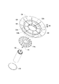
- FIG. 2 is an exploded view showing the centrifugal ceiling fan of FIG.
- FIG. 3 is a sectional view of the centrifugal ceiling fan. The structure of the centrifugal ceiling fan of this embodiment will be described with reference to FIGS. Here, only basic constituent members necessary for the present invention will be described, and other non-essential constituent members will be omitted.
- the centrifugal ceiling fan 100 of the present embodiment mainly includes a rotating part 110 and a stationary part 120.
- the rotating unit 110 includes a centrifugal impeller 114.
- the shaft 112 (see FIG. 3) rotates about the central axis AX, and rotates via power provided from the motor 130.
- the centrifugal impeller 114 is fixed to the shaft 112, and the centrifugal impeller 114 is driven and rotated through the shaft 112.
- the centrifugal impeller is a rotating device that has an impeller base and a blade portion 114a radially extending on the impeller base to increase the pressure and speed of a fluid (air in this embodiment). is there.
- the shaft 112 may be a part of the rotating part 110, the shaft 112 may be installed in a stationary part in actual operation. That is, the actual arrangement position of the shaft 112 may be changed based on actual requirements.
- the stationary part 120 includes a guide part 122 and a wind tunnel part 124.
- the guide portion 122 includes a suction port 122a and a blower port 122b.
- the guide part 122 surrounds the outside of the centrifugal impeller 114, and thus forms an air flow path between the guide part 122 and the centrifugal impeller 114.
- the centrifugal impeller 114 rotates, the air above the centrifugal ceiling fan 100 is sucked in via the suction port 122a and guided to the outlet 122b by the above-described air flow path because the centrifugal impeller 114 is rotating. Then, air is blown out of the centrifugal ceiling fan 100.
- the material of the guide part 122 is not particularly limited in the present invention, and the guide part 122 may be made of any appropriate material as necessary.
- the annular wind tunnel portion 124 has a wind tunnel inlet 124 a and a wind tunnel outlet 124 b and is disposed so as to be located on the outer side in the radial direction of the guide portion 122. .
- the annular wind tunnel portion 124 is another air flow path that surrounds the outer periphery of the guide portion 122.
- an outer shell 126 shown in FIGS. 1 and 2 is used as one form for realizing the wind tunnel portion 124.
- an annular member that opens up and down is taken as an example.
- the outer shell 126 is formed so as to surround the guide part 122 at a certain distance.
- the upper and lower openings are a wind tunnel inlet 124a and a wind tunnel exhaust 124b of the annular wind tunnel 124, respectively.
- a part of the air is sucked into the wind tunnel inlet 124a, and the sucked air passes through the wind tunnel portion 124 and then the wind tunnel. It is discharged from the exhaust port 124b.
- the material of the wind tunnel portion 124 is not particularly limited in the present invention, and the wind tunnel portion 124 may be made of any appropriate material as necessary.
- the outer shell constituting the wind tunnel portion 124 is fixed by, for example, a rib (rib) or the like through the fixing member 128 shown in FIGS.
- an air flow path is formed between the guide portion 122 and the centrifugal impeller 114.
- the air between the centrifugal ceiling fan 100 and the ceiling is sucked through the suction port 122a of the guide part 122 via the path F1.
- the air sucked through the air passage between the guide portion 122 and the centrifugal impeller 114 is discharged from the outlet 122 b of the guide portion 122.
- the main action of the annular wind tunnel portion 124 and the guide portion 122 is to guide the flow of air. Therefore, when designing the annular wind tunnel portion 124 and the guide portion, the shape of the inner peripheral surface only needs to achieve the above-described function. That is, it is only necessary that the air flow is guided and the air flowing in the annular wind tunnel portion 124 and the guide portion 122 can be merged. Although one possible design is presented here, those skilled in the art can make any suitable changes based on this description.
- a fixing member 128 for example, see FIGS. 1 and 2 that fixes the outer shell 126 that constitutes the annular wind tunnel portion 124 is also provided. The effect which leads is played.
- FIG. 4 a sectional view of the centrifugal ceiling fan of the present embodiment is shown.
- the radius R1 of the inner peripheral surface 122c gradually increases from the upper side to the lower side in the axial direction of the central axis AX.
- the radius R2 of the inner peripheral surface 124c of the annular wind tunnel portion 124 gradually decreases as it goes from the upper side in the axial direction to the lower side.
- the cross-sectional curves of the inner peripheral surfaces 122c and 124c of the guide portion and the annular wind tunnel portion satisfy the principle of hydrodynamics, and the specific curvature radius, length, etc. are particularly limited as long as the above-described shape is satisfied. do not do.
- FIG. 5 is an example of the downward view which shows a centrifugal ceiling fan in this embodiment.
- the centrifugal ceiling fan 100 further includes a plate portion 132 that covers the lower side of the centrifugal impeller 114.
- the plate portion 132 can cover the blade of the centrifugal impeller 114 and the surrounding mechanism. Therefore, the user cannot see the centrifugal impeller 114 of the rotating unit 110 and the surrounding structure, and is more secure and comfortable in use.
- the dimension of this board part 132 can be designed according to the area which covers the lower side of the centrifugal impeller 114, and if the above-mentioned function is achieved, there will be no request
- the material of the plate portion 132 there is no particular requirement for the material of the plate portion 132, and a lightweight plastic material, a high-strength plastic material, or a heat dissipation function and a material with high thermal conductivity (for example, metal, composite material) are selectable materials. .
- FIG. 6 is an example of a bottom view showing a centrifugal ceiling fan in the present embodiment.
- an illumination unit 134 is further installed on the plate portion 132. Therefore, the centrifugal ceiling fan 100 can be used as a lighting fixture in addition to a fan function for providing an air flow.
- the centrifugal ceiling fan 100 includes a power supply unit and / or a control unit required by the lighting unit 134, and this portion can be arbitrarily designed by those skilled in the art and is not shown.
- the power supply unit and / or the control unit can be arranged at any appropriate position in the centrifugal ceiling fan 100, for example, preferably arranged on the back surface of the plate portion 132.
- the lighting unit 134 is, for example, LED lighting units 134a-134e.
- the LED lighting units 134 to 134e have the advantages of power saving and high brightness.
- the control units of the LED lighting units 134 to 134e may have a dimming function, and the user can perform dimming of the lighting according to the environment and necessity.
- the LED lighting units 134 to 134e can use monochromatic light, for example, white light or warm color light, or RGB LED lighting units, and can provide more flexibility for illumination.
- a material for example, metal having a high heat dissipation function and high thermal conductivity can be used as the material of the plate portion 132.
- the centrifugal ceiling fan 100 may further include a heater so that the environment has a low temperature or a high temperature air circulation environment. If necessary, it can provide a stream of air at an appropriate temperature.
- the heater is installed at a position distant from a component (for example, the motor 130) that mainly generates heat, and the heater is installed in the annular wind tunnel 124.
- FIG. 7 shows an example of the arrangement of heaters in the centrifugal ceiling fan.
- the heater 150 can be, for example, a thin sticking type heater, and the heater 150 is disposed at, for example, the inner peripheral surface of the annular wind tunnel 124.
- the air flowing through the wind tunnel 124 is heated to blow out hotter air.
- the heater 150 may be arranged by a method in which the inner peripheral surface 124c of the annular wind tunnel portion 124 is entirely surrounded. Moreover, you may arrange
- FIG. 7B is a diagram showing an example of another heater arrangement. In addition to the form described above, one or more of a heater, an air purifier, a humidifier, and a negative ion generator can be disposed on the inner peripheral surface of the annular wind tunnel portion 124.
- FIG. 8 is a schematic view showing a centrifugal ceiling fan 100 having a wind direction adjusting unit.
- the centrifugal ceiling fan 100 may further include a wind direction adjusting unit 140.
- the wind direction adjustment unit 140 is an optional component, and is disposed, for example, at the outlet 122b of the guide portion 122 and the outlet (downstream side) of the wind tunnel inlet 124a of the annular wind tunnel 124, and thus the outlet 122b. And the flow direction of the airflow from the wind tunnel exhaust port 124b is adjusted.
- the wind direction adjustment unit 140 is basically composed of a plurality of adjustment blades.
- the blades of the wind direction adjustment unit 140 may be designed as a fixed type, a manual type, or an automation (for example, program control) according to actual requirements.
- FIG. 8 is an explanatory diagram of a form in which the plate portion 132 and the lighting unit 134 exist in the structure.
- the centrifugal ceiling fan 100 in which the plate portion 132 and the lighting unit 134 are not arranged is combined with the wind direction adjusting portion 140. You can also.
- FIG. 9 is a schematic diagram illustrating an application change example of the centrifugal ceiling fan in the present embodiment. All of the above-described embodiments have been described with a single centrifugal ceiling fan. Below, the example of application change of a centrifugal ceiling fan is demonstrated. As shown in FIG. 9, here, an example in which a plurality of centrifugal ceiling fans are arranged in parallel is shown (two are shown as an example in FIG. 9). As shown in FIG. 9, the centrifugal ceiling fans on the left and right sides generate their respective air volumes and wind pressures (indicated by dotted lines), and as described in the above-described embodiments, their respective air volumes and wind pressures are the same as those in the conventional method. Big in comparison.
- the portion surrounded by the frame A is a portion where the air blown out by the two centrifugal ceiling fans overlaps, and the air volume and the wind pressure are doubled at this place.
- the air volume and pressure further increase, and naturally double with the air flow. Accordingly, a person skilled in the art can appropriately arrange a plurality of centrifugal ceiling fans of the present invention in parallel according to the present disclosure, and this arrangement method can further adjust and increase the air volume and the wind pressure as necessary.
- the above-described embodiment is mainly an application example of a centrifugal ceiling fan.
- the present invention further provides an impeller module.
- the impeller module has a centrifugal impeller that rotates about a central axis, a suction port and a blowout port, and a guide portion that surrounds the centrifugal impeller so that air is sucked in from the suction port and air is blown out from the blowout port.
- an annular wind tunnel portion that has a wind tunnel inlet and a wind tunnel exhaust port and is located on the radially outer side of the guide portion. Since such an impeller module can provide a sufficient wind pressure and volume and can be applied to various environments, the application of the centrifugal ceiling fan is not limited.
- the centrifugal ceiling fan and the impeller module of the present invention provide sufficient wind pressure and air volume for the air blown out by the centrifugal ceiling fan of the present invention through the action of the guide portion and the wind tunnel portion. Moreover, since it has sufficient wind pressure, since a centrifugal ceiling fan can be brought closer to a ceiling, it is too low and does not bring about a human visual feeling of pressure.
- the centrifugal ceiling fan can blow a warm wind by the heater. Further, the wind direction can be freely adjusted by the wind direction adjusting unit. In addition, in conjunction with the installation of the lighting unit, the centrifugal ceiling fan can provide a lighting function.
- Centrifugal ceiling fan 110 Rotating part 112: Shaft 114: Centrifugal impeller 114a: Blade 120: Stationary part 122: Guide part 122a: Inlet 122b: Outlet 122c: Inner surface 124: Annular wind tunnel 124a: Wind tunnel inlet 124b: Wind tunnel outlet 124c: Inner surface 126: Outer shell 128: Fixed member 130: Motor 132: Plate 134: Lighting unit 134a-134e: Lighting unit 140: Wind direction adjustment part 150: Heater AX: Center axis A: Border
Landscapes
- Engineering & Computer Science (AREA)
- Mechanical Engineering (AREA)
- General Engineering & Computer Science (AREA)
- Structures Of Non-Positive Displacement Pumps (AREA)
Abstract
回転部と静止部とを有する遠心天井扇であって、回転部は、中心軸を中心に回転する遠心インペラを含む。静止部は、吸込口および吹出口を有し、吸込口から空気が吸い込まれ、吹出口から空気が吹き出されるように遠心インペラを外囲するガイド部と、風洞吸気口と風洞排気口を有し、ガイド部の径方向外側に位置する環状の風洞部とを有する遠心天井扇。
Description
本発明はインペラモジュールに関するものであり、特に、上述のインペラモジュールを使用する遠心天井扇に関する。
従来のシーリングファンは軸流型のシーリングファンであり、この様なシーリングファンは羽根を露出した状態で回転する(特許文献1)。また、ブロワ型(Blower Type)の遠心天井扇はカバー等を利用して羽根を覆っていた。しかし、軸流型のシーリングファンと比較して流量が少ないという課題があり、空気を効果的に循環させることを達成できていなかった。
したがって、如何にして体積を増大せずに、効果的にシーリングファンが吹き出す空気の流量を十分に大きく、十分に強くさせるように設計するかは注目するに値する課題である。
上述の課題を鑑みて、本発明は十分な風圧および風量を提供できる遠心天井扇およびインペラモジュールを提供する。
したがって、本発明は遠心天井扇を提供する。遠心天井扇は、回転部と静止部とを含む。回転部は、中心軸を中心に回転する遠心インペラを有する。静止部は、吸込口および吹出口を有し、吸込口から空気が吸い込まれ、吹出口から空気が吹き出されるように遠心インペラを外囲するガイド部と、風洞吸気口と風洞排気口を有し、ガイド部の径方向外側に位置する環状の風洞部とを有する。
一つの実施形態において、ガイド部の内周面は軸方向上側から下側に向かうに従って径が徐々に大きくなり、風洞部は軸方向上側から下側に向かうに従って径が徐々に小さくなる。
また、遠心天井扇において、静止部は遠心インペラの下側を覆う板部を更に含むことができる。また、板部に更に照明ユニットが配置され、照明ユニットは例えばLED照明ユニットである。
また、一つの実施形態において、遠心天井扇は、風洞部の内周面に配置されるヒータ、空気清浄器、加湿器、マイナスイオン発生器のうちの一つ、または一つ以上をさらに含む。また、もう一つの実施形態において、遠心天井扇は、吹出口および風洞排気口の下流側に配置される風向き調整部材を更に含む。
また、本発明はインペラモジュールを更に提供する。インペラモジュールは、中心軸を中心に回転する遠心インペラと、吸込口および吹出口を有し、吸込口から空気が吸い込まれ、吹出口から空気が吹き出されるように遠心インペラを外囲するガイド部と、風洞吸気口と風洞排気口を有し、ガイド部の径方向外側に位置する環状の風洞部とを有する。
また、一つの実施形態において、インペラモジュールのガイド部の内周面は軸方向上側から下側に向かうに従って径が徐々に大きくなり、風洞部は軸方向上側から下側に向かうに従って外径が徐々に小さくなる。
また、一つの実施形態において、インペラモジュールは、吹出口および風洞排気口の下流側に配置される風向き調整部材を更に含む。
上述した本発明の遠心天井扇およびインペラモジュールは、ガイド部および風洞部の作用によって、本発明の遠心天井扇が吹き出す空気の風量をさらに増加することができる。また、ヒータによって、遠心天井扇は温暖な風を吹き出すことができる。また、風向き調整部によって風向きを自由に調整することできる。他に、照明ユニットの設置と合わせ、遠心天井扇は照明の機能を提供することができる。
本発明の上述した特徴および利点をより分かり易くするために、図面と併せた幾つかの実施例を以下に説明する。
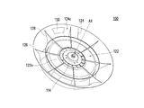
図1は、本実施形態において、遠心天井扇を示す立体概略図である。図2は、図1の遠心天井扇を示す分解図である。図3は、遠心天井扇の断面図である。図1、2、3を参考にして本実施形態の遠心天井扇の構造を説明する。ここで、本発明に必要な基本構成部材のみ説明し、その他の必須ではない構成部材については省略する。
図1、2に示すように、本実施形態の遠心天井扇100は、主に回転部110と、静止部120とを含む。回転部110は遠心インペラ114を含む。シャフト112(図3参照)は中心軸AXを中心に回転し、モータ130から提供される動力を介して回転する。また、遠心インペラ114はシャフト112に固定され、シャフト112を通して遠心インペラ114を駆動し、回転させる。一般的に、遠心インペラは、インペラベースと、インペラベース上で半径方向に放射状に延出するブレード部114aとを有し、流体(本実施形態では空気)の圧力および速度を増加させる回転装置である。また、シャフト112は回転部110の一部であってもよいが、実際の運用上、シャフト112を静止部に設置してもよい。即ち、シャフト112の実際の配置位置は実際の要求に基づいて変更してよい。
また、図3の断面概略図と合わせ、静止部120は、ガイド部122と、風洞部124とを含む。図1から図3の示すように、ガイド部122は、吸込口122aおよび吹出口122bを含む。ガイド部122は、遠心インペラ114の外側を囲い、この様にしてガイド部122と、遠心インペラ114との間に空気流路を形成する。遠心インペラ114が回転した際、遠心天井扇100上方の空気は、遠心インペラ114が回転しているため、吸込口122aを経由して吸い込まれ、上述の空気流路によって吹出口122bへ導かれて、遠心天井扇100の外へ空気が吹き出される。また、ガイド部122の材質について、本発明では特に制限せず、必要に応じて任意に適切な材質によってガイド部122を製作してよい。
同様に、図3の断面概略図と合わせ、環状の風洞部124は、風洞吸気口124aと、風洞排気口124bとを有し、ガイド部122の径方向の外側に位置するように配置される。言い換えると、本実施形態において、環状の風洞部124はガイド部122の外周を囲うもう一つの空気流路である。風洞部124を実現する一つの形態として、図1、2に示す外殻126を利用し、ここでは、環状であり且つ上下に開口する部材を例とする。外殻126は、一定の距離を隔ててガイド部122を囲うように形成される。上下の開口の部分は、それぞれ環状の風洞部124の風洞吸気口124aおよび風洞排気口124bである。本実施形態において、遠心インペラ114が回転し、遠心天井扇100上方の空気が吸い込まれる際、空気の一部分は風洞吸気口124aに吸い込まれ、吸い込まれた空気は風洞部124を通過した後、風洞排気口124bから排出される。同様に、風洞部124の材質について、本発明では特に制限せず、必要に応じて任意に適切な材質によって風洞部124を製作してよい。一般の実施上、図1、2に示す固定部材128を通して、例えば肋板(rib)等によって風洞部124を構成する外殻を固定し、ガイド部122の径方向の外周を囲む。
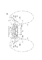
続いて、図3を参照して本実施形態の作用を説明する。図3の断面概略図に示すように、ガイド部122と、遠心インペラ114との間に空気流路が形成される。遠心インペラ114の回転によって、遠心天井扇100上方と、天井との間の空気は、経路F1を経由し、ガイド部122の吸込口122a通じて吸い込まれる。その後、ガイド部122と、遠心インペラ114との間の空気流路を通過して、吸い込まれた空気がガイド部122の吹出口122bから排出される。
また、遠心天井扇100上方の空気の一部分は、経路F2に沿って、環状の風洞部124の風洞吸気口124aを通じて吸い込まれ、環状の風洞部124を経由し、風洞排気口124bから空気が排出される。その後、ガイド部122の吹出口122bを経由して排出された空気、および環状の風洞部124の風洞排気口124bを経由して排出された空気は遠心天井扇100の下方(下流側)Pで一つに合流してから、経路F3を経由して環境空間へ吹き出される。その後、空気はまた遠心天井扇100の上流側へ上昇し、再び経路F1,F2に沿ってそれぞれ遠心天井扇100へ入り、このプロセスが継続的に繰り返される。
次に本実施形態の環状の風洞部124およびガイド部122の構造について説明する。環状の風洞部124およびガイド部122の主な作用は空気の流動を導くことである。したがって、環状の風洞部124およびガイド部を設計する際、その内周面の形状は上述した機能を達成できればよい。すなわち、空気流を導き、環状の風洞部124およびガイド部122で流動する空気を合流できればよい。ここでは、一つの可能な設計を提示しているが、当業者はこの説明に基づいて任意に適当な変更を行うことができる。環状の風洞部124及びガイド部122が空気の流動を導く作用を奏する他、環状の風洞部124を構成する外殻126を固定する固定部材128(例えば、図1,2参照)も空気の流動を導く作用を奏する。
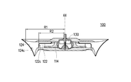
図4に示すように、本実施形態の遠心天井扇の断面図が示されている。説明の便宜のため、この断面図では環状の風洞部およびガイド部の内周面の断面曲線のみ強調してある。ガイド部122に関して、その内周面122cの半径R1は、中心軸AXの軸方向の上側から下側に向かうにつれて徐々に大きくなる。また、環状の風洞部124の内周面124cの半径R2は、上述の軸方向の上側から下側に向かうにつれて徐々に小さくなる。設計上、ガイド部および環状の風洞部の内周面122c、124cの断面曲線は流体力学の原理を満たすと共に、上述の形状を満たせば、その具体的な曲率半径、長さ等などは特に制限しない。
また、図5は本実施形態において、遠心天井扇を示す下方視図の例である。遠心天井扇100は、遠心インペラ114の下側を覆う板部132を更に含む。この板部132は、遠心インペラ114のブレードおよびその周囲の機構を覆うことができる。よって、ユーザは、回転部110の遠心インペラ114およびその周辺の構造体が見えず、使用上更に安心および快適である。また、この板部132の寸法は遠心インペラ114の下側を覆う面積に合わせて設計することができ、上述の機能が達成できれば、寸法に関して特に要求は無い。また、板部132の材料についても特に要求は無く、軽量化のプラスチック材質、高強度のプラスチック材質、或いは放熱機能、熱伝導率の高い材質(例えば金属、複合材料)は選択可能な材料である。
また、図6は本実施形態において、遠心天井扇を示す底面図の例である。図5との差異は、本実施形態には、板部132に照明ユニット134が更に設置されている。したがって、遠心天井扇100は、空気流を提供する扇風機機能の他、更に照明器具としても用いることができる。この実施形態では、遠心天井扇100は、照明ユニット134が必要とする電源ユニットおよび/または制御ユニットを含み、この部分は当業者が任意に設計することができるので、図示しない。電源ユニットおよび/或いは制御ユニットは、遠心天井扇100内に任意の適切な位置に配置させることができ、例えば、好ましくは板部132の背面に配置される。
もう一つの実施形態において、照明ユニット134は、例えば、LED照明ユニット134a~134eである。LED照明ユニット134~134eは、節電および高輝度のメリットを有する。また、LED照明ユニット134~134eの制御ユニットは調光機能を合わせてもよく、ユーザは環境や、必要に応じて照明の調光を行うことができる。また、LED照明ユニット134~134eには、単色光を使用することができ、例えば、白色光又は暖色系の光、或いはRGBのLED照明ユニットであり、イルミネーションに更に柔軟性をもたせることができる。また、本実施形態の照明ユニットと合わせ、板部132の材料として放熱機能、熱伝導率の高い材質(例えば金属)を使用することができる。
また、ユーザが、本発明の遠心天井扇100を使用する際に、各種の気候に適用するため、遠心天井扇100はヒータを更に含んでも良く、気温が低い環境或いは温度の高い空気循環環境が必要であれば、適切な温度の空気流を提供できる。本実施形態において、ヒータは主に発熱する構成部材(例えばモータ130等)から離れた位置に設置され、ヒータを環状の風洞部124に設置するのは好ましい形態である。図7は遠心天井扇において、ヒータの配置を示す例である。図7Aに示すように、ヒータ150は、例えば薄型の貼り付けタイプのヒータを採用することができ、ヒータ150の配置位置を例えば環状の風洞部124の内周面にし、この様にして環状の風洞部124に流れる空気を加熱し、より熱い空気を吹き出す。また、ヒータ150は、環状の風洞部124の内周面124cをまるまる一周囲む方法によって配置されてもよい。また必要に応じて風洞部124の内周面124cの任意の箇所に、任意の数で配置してもよい。図7Bは、もう一つのヒータの配置の範例を示す図である。上述した形態以外に、環状の風洞部124の内周面にヒータ、空気清浄器、加湿器、マイナスイオン発生器のうちの一つ、または一つ以上を配置することもできる。
図8は、風向き調整部を有する遠心天井扇100を示す概略図である。図8に示すように、遠心天井扇100は、更に風向き調整部140を含んでも良い。この風向き調整部140はオプションとしての構成部材であり、例えばガイド部122の吹出口122bおよび環状の風洞部124の風洞吸気口124aの出口(下流側)に配置され、この様にして吹出口122bおよび風洞排気口124bからの気流の流動方向を調整する。また、図8に示すように、風向き調整部140は、基本的には複数の調整ブレードによって構成される。風向き調整部140のブレードは実際の要求によって固定式、手動式又は自動化(例えばプログラム制御)として設計してよい。図8は、構造に板部132および照明ユニット134が存在する形態の説明図であるが、当然ながら、板部132及び照明ユニット134を配置しない遠心天井扇100がこの風向き調整部140に組み合わせられることもできる。
図9は、本実施形態において、遠心天井扇の応用変化例を示す概略図である。上述した実施例は、何れも単一の遠心天井扇によって説明している。以下は、遠心天井扇の応用変化例を説明する。図9に示すように、ここで、複数の遠心天井扇を並列配置した例を示す(図9に、例として2個示してある)。図9に示すように、左右両側の各遠心天井扇は、それぞれの風量および風圧(点線によって表示)を発生させ、前述した実施例で述べたように、各自の風量および風圧は従来の方法と比較して大きい。また、枠線Aによって囲まれた部分は二つの遠心天井扇の吹き出す空気が重なる部分であり、この場所で風量および風圧は倍増する。その結果、風量と圧力は更に増加し、当然気流も伴って倍増する。従って、当業者は、当開示によって、本発明の遠心天井扇を適宜に複数並列配置することができ、この配置方法によって、必要に応じて風量および風圧を更に調整および増大することができる。
上述の実施形態は主に、遠心天井扇の応用例である。これ以外に、本発明は、インペラモジュールを更に提供する。インペラモジュールは、中心軸を中心に回転する遠心インペラと、吸込口および吹出口を有し、吸込口から空気が吸い込まれ、吹出口から空気が吹き出されるように遠心インペラを外囲するガイド部と、風洞吸気口と風洞排気口を有し、ガイド部の径方向外側に位置する環状の風洞部とを含む。この様なインペラモジュールによって、十分な風圧および風量を提供し、各種の様々な環境に応用させる事が出来るため、遠心天井扇の応用は制限されない。
上記の通り、本発明の遠心天井扇およびインペラモジュールは、ガイド部および風洞部の作用を通して、本発明の遠心天井扇が吹き出す空気に十分な風圧と風量を提供する。また、十分な風圧を有するため、遠心天井扇を、より天井に近づけることができるため、低すぎて人の視覚的圧迫感をもたらすことがない。
また、ヒータによって、遠心天井扇は温暖な風を吹き出すことが出来る。また、風向き調整部によって風向きを自由に調整できる。他に、照明ユニットの設置と合わせ、遠心天井扇は照明の機能を提供することができる。
以上のごとく、この発明を実施例により開示したが、もとより、この発明を限定するためのものではなく、当業者であれば容易に理解できるように、この発明の技術思想の範囲内において、適当な変更ならびに修正が当然なされうるものであるから、その特許権保護の範囲は、特許請求の範囲および、それと均等な領域を基準として定めなければならない。
100: 遠心天井扇
110: 回転部 112:シャフト
114: 遠心インペラ 114a:ブレード
120: 静止部 122:ガイド部
122a:吸込口 122b:吹出口
122c: 内周面
124:環状の 風洞部
124a:風洞吸気口 124b:風洞排気口
124c: 内周面
126: 外殻 128:固定部材
130: モータ 132:板部
134: 照明ユニット 134a~134e:照明ユニット
140: 風向き調整部 150:ヒータ
AX: 中心軸
A:枠線
110: 回転部 112:シャフト
114: 遠心インペラ 114a:ブレード
120: 静止部 122:ガイド部
122a:吸込口 122b:吹出口
122c: 内周面
124:環状の 風洞部
124a:風洞吸気口 124b:風洞排気口
124c: 内周面
126: 外殻 128:固定部材
130: モータ 132:板部
134: 照明ユニット 134a~134e:照明ユニット
140: 風向き調整部 150:ヒータ
AX: 中心軸
A:枠線
Claims (10)
- 回転部と静止部とを有する遠心天井扇であって、
前記回転部は、
中心軸を中心に回転する遠心インペラを有し、
前記静止部は、
吸込口および吹出口を有し、前記吸込口から空気が吸い込まれ、前記吹出口から空気が吹き出されるように前記遠心インペラを外囲するガイド部と、
風洞吸気口と風洞排気口を有し、前記ガイド部の径方向外側に位置する環状の風洞部と、
を有する遠心天井扇。 - 前記ガイド部の内周面は軸方向上側から下側に向かうに従って径が徐々に大きくなり、
前記風洞部は前記軸方向上側から下側に向かうに従って外径が徐々に小さくなる請求項1に記載の遠心天井扇。 - 前記静止部は前記遠心インペラの下側を覆う板部を更に含む請求項1に記載の遠心天井扇。
- 前記板部に照明ユニットが配置される請求項3に記載の遠心天井扇。
- 前記照明ユニットがLED照明ユニットである請求項4に記載の遠心天井扇。
- 前記風洞部の内周面に配置されるヒータ、空気清浄器、加湿器、マイナスイオン発生器の内の一つ、または一つ以上をさらに含む請求項1に記載の遠心天井扇。
- 前記吹出口および前記風洞排気口の下流側に配置される風向き調整部材を更に含む請求項1に記載の遠心天井扇。
- 中心軸を中心に回転する遠心インペラと、
吸込口および吹出口を有し、前記吸込口から空気が吸い込まれ、前記吹出口から空気が吹き出されるように前記遠心インペラを外囲するガイド部と、
風洞吸気口と風洞排気口を有し、前記ガイド部の径方向外側に位置する環状の風洞部と、
を有するインペラモジュール。 - 前記ガイド部の内周面は前記遠心天井扇の軸方向上側から下側に向かうに従って径が徐々に大きくなり、
前記風洞部は前記遠心天井扇の前記軸方向上側から下側に向かうに従って外径が徐々に小さくなる請求項8に記載のインペラモジュール。 - 前記吹出口および前記風洞排気口の下流側に配置される風向き調整部材を更に含む請求項8に記載のインペラモジュール。
Priority Applications (2)
| Application Number | Priority Date | Filing Date | Title |
|---|---|---|---|
| CN201680090679.5A CN109923316A (zh) | 2016-11-08 | 2016-11-08 | 离心吊扇和叶轮模块 |
| PCT/JP2016/083034 WO2018087797A1 (ja) | 2016-11-08 | 2016-11-08 | 遠心天井扇およびインペラモジュール |
Applications Claiming Priority (1)
| Application Number | Priority Date | Filing Date | Title |
|---|---|---|---|
| PCT/JP2016/083034 WO2018087797A1 (ja) | 2016-11-08 | 2016-11-08 | 遠心天井扇およびインペラモジュール |
Publications (1)
| Publication Number | Publication Date |
|---|---|
| WO2018087797A1 true WO2018087797A1 (ja) | 2018-05-17 |
Family
ID=62109662
Family Applications (1)
| Application Number | Title | Priority Date | Filing Date |
|---|---|---|---|
| PCT/JP2016/083034 Ceased WO2018087797A1 (ja) | 2016-11-08 | 2016-11-08 | 遠心天井扇およびインペラモジュール |
Country Status (2)
| Country | Link |
|---|---|
| CN (1) | CN109923316A (ja) |
| WO (1) | WO2018087797A1 (ja) |
Citations (4)
| Publication number | Priority date | Publication date | Assignee | Title |
|---|---|---|---|---|
| JPS6146212U (ja) * | 1984-08-31 | 1986-03-27 | 富士電機株式会社 | 車両用天井扇 |
| JP2001017526A (ja) * | 1999-07-07 | 2001-01-23 | Matsushita Electric Ind Co Ltd | 空気調和装置および集塵具 |
| JP2003307198A (ja) * | 2002-04-12 | 2003-10-31 | Mitsubishi Electric Corp | 送風機 |
| JP2012215162A (ja) * | 2011-03-29 | 2012-11-08 | Panasonic Corp | 涼風機 |
Family Cites Families (4)
| Publication number | Priority date | Publication date | Assignee | Title |
|---|---|---|---|---|
| AUPN102795A0 (en) * | 1995-02-10 | 1995-03-09 | Magiview Pty Ltd | Circulation control fan |
| JP3913334B2 (ja) * | 1996-11-20 | 2007-05-09 | 三菱電機株式会社 | 換気送風装置および換気送風システム |
| WO2011129073A1 (ja) * | 2010-04-15 | 2011-10-20 | パナソニック株式会社 | 天井扇 |
| JP6139171B2 (ja) * | 2013-02-20 | 2017-05-31 | シャープ株式会社 | 送風機 |
-
2016
- 2016-11-08 CN CN201680090679.5A patent/CN109923316A/zh active Pending
- 2016-11-08 WO PCT/JP2016/083034 patent/WO2018087797A1/ja not_active Ceased
Patent Citations (4)
| Publication number | Priority date | Publication date | Assignee | Title |
|---|---|---|---|---|
| JPS6146212U (ja) * | 1984-08-31 | 1986-03-27 | 富士電機株式会社 | 車両用天井扇 |
| JP2001017526A (ja) * | 1999-07-07 | 2001-01-23 | Matsushita Electric Ind Co Ltd | 空気調和装置および集塵具 |
| JP2003307198A (ja) * | 2002-04-12 | 2003-10-31 | Mitsubishi Electric Corp | 送風機 |
| JP2012215162A (ja) * | 2011-03-29 | 2012-11-08 | Panasonic Corp | 涼風機 |
Also Published As
| Publication number | Publication date |
|---|---|
| CN109923316A (zh) | 2019-06-21 |
Similar Documents
| Publication | Publication Date | Title |
|---|---|---|
| CN102679198B (zh) | 灯具 | |
| CN103383069B (zh) | 灯具 | |
| TW201248071A (en) | LED lamp | |
| CN212390461U (zh) | 具有照明功能的环形暖风口取暖器 | |
| US20130120972A1 (en) | Pendent lamp having an air conditioning function | |
| CN104236049A (zh) | 空气调节器 | |
| CN105588185A (zh) | 一种风管机及空调器 | |
| JP2007085352A (ja) | ファン及びそのファンフレーム | |
| TWI638099B (zh) | 離心吸頂扇和離心葉輪模組 | |
| WO2018087797A1 (ja) | 遠心天井扇およびインペラモジュール | |
| CN107654418A (zh) | 防止内部空气回流的离心风机 | |
| US20190242404A1 (en) | Fan assemblies | |
| CN206386769U (zh) | 螺旋导风装置及设有该螺旋导风装置的舞台灯散热系统 | |
| CN204678181U (zh) | 一种自动降温led面板灯 | |
| JP2003157715A (ja) | 光源ランプ冷却構造 | |
| JP5923686B2 (ja) | 涼風機 | |
| JP7348500B2 (ja) | ターボファン | |
| CN101963746B (zh) | 光源模组及投影机 | |
| JP2015068298A (ja) | 送風装置 | |
| CN208295868U (zh) | 灯具内部散热结构 | |
| CN218954839U (zh) | 照明装置 | |
| CN205481625U (zh) | 空调机 | |
| TWM596854U (zh) | 風路裝置 | |
| CN223049046U (zh) | 一种侧出风的风扇灯 | |
| CN101082761A (zh) | 电子装置 |
Legal Events
| Date | Code | Title | Description |
|---|---|---|---|
| 121 | Ep: the epo has been informed by wipo that ep was designated in this application |
Ref document number: 16921244 Country of ref document: EP Kind code of ref document: A1 |
|
| NENP | Non-entry into the national phase |
Ref country code: DE |
|
| 122 | Ep: pct application non-entry in european phase |
Ref document number: 16921244 Country of ref document: EP Kind code of ref document: A1 |
|
| NENP | Non-entry into the national phase |
Ref country code: JP |