WO2018083932A1 - 充電率推定装置及び充電率推定方法 - Google Patents
充電率推定装置及び充電率推定方法 Download PDFInfo
- Publication number
- WO2018083932A1 WO2018083932A1 PCT/JP2017/036038 JP2017036038W WO2018083932A1 WO 2018083932 A1 WO2018083932 A1 WO 2018083932A1 JP 2017036038 W JP2017036038 W JP 2017036038W WO 2018083932 A1 WO2018083932 A1 WO 2018083932A1
- Authority
- WO
- WIPO (PCT)
- Prior art keywords
- battery
- charging rate
- rate estimation
- soc
- observer
- Prior art date
Links
Images


Classifications
-
- G—PHYSICS
- G01—MEASURING; TESTING
- G01R—MEASURING ELECTRIC VARIABLES; MEASURING MAGNETIC VARIABLES
- G01R31/00—Arrangements for testing electric properties; Arrangements for locating electric faults; Arrangements for electrical testing characterised by what is being tested not provided for elsewhere
- G01R31/36—Arrangements for testing, measuring or monitoring the electrical condition of accumulators or electric batteries, e.g. capacity or state of charge [SoC]
- G01R31/367—Software therefor, e.g. for battery testing using modelling or look-up tables
-
- H—ELECTRICITY
- H01—ELECTRIC ELEMENTS
- H01M—PROCESSES OR MEANS, e.g. BATTERIES, FOR THE DIRECT CONVERSION OF CHEMICAL ENERGY INTO ELECTRICAL ENERGY
- H01M10/00—Secondary cells; Manufacture thereof
- H01M10/42—Methods or arrangements for servicing or maintenance of secondary cells or secondary half-cells
- H01M10/48—Accumulators combined with arrangements for measuring, testing or indicating the condition of cells, e.g. the level or density of the electrolyte
-
- G—PHYSICS
- G01—MEASURING; TESTING
- G01R—MEASURING ELECTRIC VARIABLES; MEASURING MAGNETIC VARIABLES
- G01R31/00—Arrangements for testing electric properties; Arrangements for locating electric faults; Arrangements for electrical testing characterised by what is being tested not provided for elsewhere
- G01R31/36—Arrangements for testing, measuring or monitoring the electrical condition of accumulators or electric batteries, e.g. capacity or state of charge [SoC]
- G01R31/385—Arrangements for measuring battery or accumulator variables
- G01R31/387—Determining ampere-hour charge capacity or SoC
- G01R31/388—Determining ampere-hour charge capacity or SoC involving voltage measurements
-
- H—ELECTRICITY
- H02—GENERATION; CONVERSION OR DISTRIBUTION OF ELECTRIC POWER
- H02J—CIRCUIT ARRANGEMENTS OR SYSTEMS FOR SUPPLYING OR DISTRIBUTING ELECTRIC POWER; SYSTEMS FOR STORING ELECTRIC ENERGY
- H02J7/00—Circuit arrangements for charging or depolarising batteries or for supplying loads from batteries
-
- G—PHYSICS
- G01—MEASURING; TESTING
- G01R—MEASURING ELECTRIC VARIABLES; MEASURING MAGNETIC VARIABLES
- G01R31/00—Arrangements for testing electric properties; Arrangements for locating electric faults; Arrangements for electrical testing characterised by what is being tested not provided for elsewhere
- G01R31/36—Arrangements for testing, measuring or monitoring the electrical condition of accumulators or electric batteries, e.g. capacity or state of charge [SoC]
- G01R31/389—Measuring internal impedance, internal conductance or related variables
-
- Y—GENERAL TAGGING OF NEW TECHNOLOGICAL DEVELOPMENTS; GENERAL TAGGING OF CROSS-SECTIONAL TECHNOLOGIES SPANNING OVER SEVERAL SECTIONS OF THE IPC; TECHNICAL SUBJECTS COVERED BY FORMER USPC CROSS-REFERENCE ART COLLECTIONS [XRACs] AND DIGESTS
- Y02—TECHNOLOGIES OR APPLICATIONS FOR MITIGATION OR ADAPTATION AGAINST CLIMATE CHANGE
- Y02E—REDUCTION OF GREENHOUSE GAS [GHG] EMISSIONS, RELATED TO ENERGY GENERATION, TRANSMISSION OR DISTRIBUTION
- Y02E60/00—Enabling technologies; Technologies with a potential or indirect contribution to GHG emissions mitigation
- Y02E60/10—Energy storage using batteries
Definitions
- the present invention relates to a charging rate estimation device and a charging rate estimation method.
- Patent Document 1 A device that estimates the battery charge rate having a hysteresis in the relationship between the battery charge rate and the open circuit voltage is known (for example, Patent Document 1).
- the battery charge rate can be estimated based on the battery model.
- the parameter representing the battery model is likely to change.
- An error in the parameter due to a change in the parameter representing the battery model can reduce the estimation accuracy of the charging rate of the battery.
- An object of the present invention made in view of such circumstances is to provide a charging rate estimation device and a charging rate estimation method capable of improving the estimation accuracy of the charging rate of a battery.
- the charging rate estimation device estimates the charging rate of the battery using an observer based on a battery model.
- the model includes hysteresis characteristics.
- a charging rate estimation method includes a step of estimating the charging rate of the battery using an observer based on a battery model.
- the model includes hysteresis characteristics.
- the estimation accuracy of the charging rate of the battery can be improved.
- the estimation accuracy of the battery charging rate can be improved.
- FIG. 6 It is a functional block diagram which shows the schematic structural example of a charging rate estimation apparatus. It is a figure which shows an example of a battery equivalent circuit. This is an nth-order Foster-type RC ladder circuit. This is an nth-order Cowell RC ladder circuit. It is a figure which shows an example of a SOC-OCV characteristic. It is a figure which shows an example of the SOC-OCV characteristic which has a hysteresis. It is a figure which shows the example of the battery equivalent circuit containing a hysteresis voltage. It is a figure which shows the example of the battery equivalent circuit which replaced the Warburg impedance of FIG. 6 with the Foster type
- the charging rate estimation device may be mounted on a vehicle such as an electric vehicle or a hybrid electric vehicle.
- the charging rate estimation device may estimate a charging rate of a vehicle battery.
- the vehicle is mounted with an electric motor, a battery, and a controller for driving the vehicle.
- the battery is discharged to supply electric power to the electric motor, regeneratively charged from the electric motor during braking, or charged from the ground charging facility.
- the charging rate estimation device may estimate the charging rate of the battery based on the charge / discharge current flowing through the battery and the terminal voltage of the battery.
- the charging rate estimation device 1 is connected to a battery 4 via a current sensor 2 and a voltage sensor 3.
- the charging rate estimation device 1 may include a current sensor 2 or a voltage sensor 3.
- the charging rate estimation device 1 may be connected to the power supply device 5.
- the charging rate estimation device 1 may input a charging / discharging current from the power supply device 5 to the battery 4.
- the power supply device 5 may be a current source, for example.
- the charging rate estimation device 1 may include a power supply device 5.
- the current sensor 2 detects a charge / discharge current for the battery 4.
- the charge / discharge current is represented by u (t) that is a function of time (t).
- the current sensor 2 outputs the detected charging / discharging current to the charging rate estimation device 1.
- the voltage sensor 3 detects the terminal voltage of the battery 4. In the present embodiment, it is assumed that the terminal voltage is represented by y (t) that is a function of time (t). The voltage sensor 3 outputs the detected terminal voltage to the charging rate estimation device 1.
- the battery 4 may be a secondary battery, for example.
- the secondary battery is also called a rechargeable battery.
- the battery 4 is assumed to be a lithium ion battery in this embodiment.
- the battery 4 may be another type of battery.
- the charging rate estimation device 1 includes a control unit 10 and a storage unit 20.
- the control unit 10 controls each component of the charging rate estimation device 1.
- the control unit 10 may be configured with, for example, a processor or a microcomputer.
- the storage unit 20 may be composed of, for example, a semiconductor memory or a magnetic storage device.
- the control unit 10 may store data or information handled by the charging rate estimation device 1 in the storage unit 20.
- the control unit 10 acquires the charge / discharge current and the terminal voltage of the battery 4 from the current sensor 2 and the voltage sensor 3, respectively.
- the control unit 10 may estimate the internal state of the battery 4 based on the charge / discharge current of the battery 4 and the terminal voltage.
- the internal state of the battery 4 can be represented by a model including the open circuit voltage of the battery 4 and the overvoltage generated inside the battery 4 as parameters.
- the open circuit voltage is also called OCV (Open (Circuit Voltage).
- OCV Open (Circuit Voltage).
- the OCV is a potential difference between the electrodes in the electrochemical equilibrium state of the battery 4.
- the OCV corresponds to the terminal voltage of the battery 4 when no charge / discharge current flows through the battery 4.
- Overvoltage corresponds to the magnitude of the voltage drop caused by the internal impedance.
- the internal impedance is determined according to the reaction rate of the electrochemical reaction inside the battery 4.
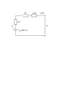
- the model representing the internal state of the battery 4 can be approximated by a battery equivalent circuit as shown in FIG.
- a model approximated by a battery equivalent circuit is also called a battery model.
- the input of the battery equivalent circuit corresponds to the charge / discharge current flowing through the battery 4 and is indicated as u (t).
- u (t) represents the direction of current for charging the battery 4. It is assumed that u (t) is a positive value when a current for charging the battery 4 flows. When the discharge current flows from the battery 4, it is assumed that u (t) has a negative value.
- the output of the battery equivalent circuit corresponds to the terminal voltage of the battery 4 and is shown as y (t). In FIG. 2, it is assumed that the terminal on the tip side of the arrow marked with y (t) corresponds to the positive terminal of the battery 4.
- the OCV of the battery 4 is represented by a voltage source 201 in the battery equivalent circuit.
- the voltage output from the voltage source 201 is represented by OCV (t) that is a function of time.
- the internal impedance of the battery 4 is represented as a circuit in which a resistance indicated by R 0 and a Warburg impedance indicated by Z w (p) are connected in series.
- the resistance indicated by R 0 represents the resistance resulting from the migration process or the like in the electrolyte solution of the battery 4.
- the Warburg impedance represents an impedance resulting from a diffusion process of ions in the battery 4 or the like.
- the overvoltage of the battery 4 is expressed as a voltage drop generated in the internal impedance of the battery 4 due to the current flowing in the battery equivalent circuit.
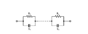
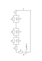
- Warburg impedance for example as shown in Figure 3A, is represented as n-order Foster type circuit parallel circuit is the n connected in series with the capacitor shown as resistor and C 1 ⁇ C n shown as R 1 ⁇ R n It's okay.
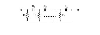
- each of n resistors indicated as R 1 to R n is connected in parallel between n capacitors (C 1 to C n ) connected in series as shown in FIG. 3B. It may also be expressed as an nth order Cowell type circuit.
- the Warburg impedance may be expressed using other linear transfer function models.
- the parameters of the battery equivalent circuit approximating the battery 4 include the resistance value of the resistor constituting the Warburg impedance and the capacitance of the capacitor.
- the parameter of the battery equivalent circuit may be set in advance.
- the parameters of the battery model may be held by the control unit 10 or may be stored in the storage unit 20.
- the control unit 10 estimates the internal state of the battery 4 based on the parameters of the battery equivalent circuit, the charge / discharge current flowing through the battery 4, and the terminal voltage of the battery 4. In the present embodiment, the control unit 10 estimates the charging rate and overvoltage of the battery 4 as the internal state of the battery 4.
- the charge rate of the battery 4 is a ratio of the charge amount to the charge capacity of the battery 4.
- the charging rate is also referred to as SOC (State Of) Charge). It is assumed that the control unit 10 does not estimate the resistance value of the resistor constituting the internal impedance of the battery 4 and the capacitance of the capacitor.
- the controller 10 is not limited to a configuration that does not estimate the resistance value and the capacitance included in the internal impedance.
- the control unit 10 may be configured to estimate a resistance value and a capacity included in the internal impedance.
- the control unit 10 may estimate the OCV and overvoltage of the battery 4. In this case, the control unit 10 can estimate the SOC of the battery 4 based on the OCV of the battery 4.
- the OCV of the battery 4 can be expressed as a function of the SOC.
- the relationship between SOC and OCV is referred to as SOC-OCV characteristics.
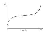
- the SOC-OCV characteristic can be represented by a graph shown in FIG. 4, for example.
- the horizontal axis and vertical axis in FIG. 4 indicate SOC and OCV, respectively.
- the SOC-OCV characteristic can be obtained in advance by experiments or the like.
- the control unit 10 can estimate the OCV of the battery 4 based on the SOC-OCV characteristic of the battery 4 and the estimated value of the SOC of the battery 4.
- the SOC-OCV characteristic may have a hysteresis characteristic.
- the SOC-OCV characteristics having hysteresis characteristics are different in characteristics during charging and characteristics during discharging.
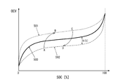
- the SOC-OCV characteristic having the hysteresis characteristic is shown, for example, as shown in FIG.
- the horizontal axis and the vertical axis in FIG. 5 indicate SOC and OCV, respectively.
- the charging SOC-OCV characteristic 501 indicating the SOC-OCV characteristic during charging of the battery 4 is indicated by a broken line.
- a discharge SOC-OCV characteristic 502 indicating an SOC-OCV characteristic at the time of discharging of the battery 4 is indicated by a one-dot chain line.
- the charge SOC-OCV characteristic 501 and the discharge SOC-OCV characteristic 502 form a loop of the SOC-OCV characteristic.
- the loop of the SOC-OCV characteristic formed by the charging SOC-OCV characteristic 501 and the discharging SOC-OCV characteristic 502 is also called a major loop.
- the major loop can be obtained by an experiment of charging / discharging the battery 4.
- the battery 4 is not always charged after being discharged until the SOC becomes 0%.
- the battery 4 can exhibit an SOC-OCV characteristic indicated by a path from the point A to the point B by being charged after being discharged to the point A in FIG.
- the battery 4 is not necessarily discharged after being charged until the SOC reaches 100%.
- the battery 4 can exhibit an SOC-OCV characteristic indicated by a path from the point C to the point D by being discharged after being charged to the point C in FIG.
- a loop having SOC-OCV characteristics smaller than the major loop, which is indicated by a path connected in the order of point A, point B, point C, point D, and point A is also referred to as a minor loop.
- the minor loop can exist virtually infinitely. Minor loops are less likely to be obtained by prior experimentation compared to major loops.
- the SOC-OCV characteristic 500 indicated by a solid line in FIG. 5 corresponds to the average value of the charging SOC-OCV characteristic 501 and the discharging SOC-OCV characteristic 502.
- the SOC-OCV characteristic 500 is not limited to the average value of the charge SOC-OCV characteristic 501 and the discharge SOC-OCV characteristic 502.
- the SOC-OCV characteristic 500 may be a graph included between the charge SOC-OCV characteristic 501 and the discharge SOC-OCV characteristic 502.
- the difference in OCV between the SOC-OCV characteristic 500 and the major loop is also referred to as a hysteresis voltage.
- h (t) The SOC-OCV characteristic having hysteresis can be expressed by the following equation (1) including a hysteresis voltage, instead of being expressed by a minor loop that can exist virtually infinitely.
- f OCV ( ⁇ ) is a function representing the SOC-OCV characteristics 500.
- the SOC-OCV characteristic is expressed as in Expression (1), when the control unit 10 estimates the internal state of the battery 4 together with h (t), the SOC-OCV characteristic is estimated. The accuracy of the conversion can be improved.
- the battery equivalent circuit is expressed as shown in FIG.
- the battery equivalent circuit of FIG. 6 is different from the battery of FIG. 2 in that h (t) representing a hysteresis voltage is added and the output voltage of the voltage source 201 is represented as f OCV (SOC (t)). Different from equivalent circuit.
- the Warburg impedance is represented by a Foster-type circuit shown in FIG. 3A.
- the battery equivalent circuit is expressed as shown in FIG.
- the battery equivalent circuit of FIG. 7 differs from the battery equivalent circuit of FIG. 6 in that Z w (p) is replaced with a Foster-type circuit.
- v k (t) represents the voltage drop that occurs at the capacitance denoted as C k .
- k is an integer of 1 to n.
- the behavior of h (t) is expressed by the following equation (2).
- ⁇ represents the voltage drop speed of the hysteresis model.
- m represents the maximum value of the hysteresis voltage.
- the SOC (t) of the battery 4 at time (t) can be calculated by the following equation (3).
- t 0 represents the measurement start time.
- the integral of the second term on the right side of Equation (3) represents the amount of charge that enters and exits the battery 4 calculated by integrating the charge / discharge current.
- the overvoltage is expressed as the following expression (4) based on the internal impedance of the battery 4 and the charge / discharge current of the battery 4.
- ⁇ (t) represents an overvoltage.
- G ⁇ (p) represents the internal impedance and is the sum of R 0 and Z w (p).
- Z w (p) is expressed by the following equation (5).
- R d represents a diffusion resistance
- C d represents the diffusion capacity.
- the battery model represented by the battery equivalent circuit of FIG. 7 is represented by an input / output system that takes charge / discharge current as an input and terminal voltage as an output.
- An input / output system is also simply called a system.
- the input / output system can be represented as a state space represented by the following equations (8) and (9).
- Equation (8) is a state equation representing the relationship between the input and the state variable.
- Expression (9) is an output equation representing the relationship between the state variable and the output.
- a (u (t)) in the equation (8) is a (n + 2) ⁇ (n + 2) -order matrix in the real space, and is represented by the following equation (10).
- diag is a function that outputs a diagonal matrix.
- a (u (t)) is also called a system matrix.
- the system matrix represents at least some of the characteristics of the system.
- the system matrix of equation (8) depends on u (t), which represents the input to the system. Therefore, it can be said that the system represented by the equations (8) and (9) is a parameter variable system.
- the parameter variable system is also called a PV (Parameter Varying) system.
- the model of the battery 4 represented by the battery model of FIG. 7 can be represented by a PV system.
- X (t) in the equations (8) and (9) is a state variable, and is represented by the following equation (13).
- the charging rate estimation apparatus 1 can estimate the internal state of the battery 4 by estimating the state variable in the PV system representing the model of the battery 4.
- the control unit 10 inputs the charge / discharge current acquired from the current sensor 2 to the model of the battery 4 and calculates an estimated value of the terminal voltage.
- the control unit 10 feeds back the difference between the estimated value of the terminal voltage and the actual terminal voltage to the model of the battery 4 and sequentially estimates the SOC of the battery 4.
- the PV system representing the model of the battery 4 is a linear parameter variable system.
- the linear parameter variable system is also called an LPV (LinearLineParameter Varying) system.
- LPV LinearLineParameter Varying
- the LPV system can be expressed as a state space represented by the following equations (14) to (18). As shown in the equations (16) to (18), A as the system matrix can be expressed in a polytope form.
- the polytope format is a format in which a function is expressed by a linear combination. The primary combination is also called a linear combination.
- Expression (14) is a state equation representing a relationship between an input to the system and a state variable representing an internal state of the system.
- Equation (15) is an output equation representing the relationship between the state variable and the output from the system.
- x (t) is an nth-order column vector in real space and represents a state variable.
- u (t) is a nu- order column vector in real space and represents an input to the system.
- y (t) is an n y -th order column vector in real space and represents the output from the system.
- n, n u and n y are set according to the state, the size of the input and output signals, respectively.
- the size of the matrix represented as A ( ⁇ (t)), B, and C is set according to the size of each signal.
- U (t) which is an input to the system represented by equations (14) and (15), is a vector and is written in bold.
- U (t) which is an input to the system represented by the equations (8) and (9), is a scalar and is written in fine characters.
- u (t) representing a vector is represented as u ⁇ (t) below.
- x (t) and y (t) representing vectors are represented as x ⁇ (t) and y ⁇ (t), respectively.
- represents the norm.
- the norm of the signal represents the magnitude of the signal.
- represents the magnitude of x (t).
- 2 represents the L 2 norm.
- the L 2 norm is calculated as the square root of the value obtained by squaring the components included in the signal.
- L 2 norm is a kind of norm. Symbols, denoted L 2 in formula (21) shows the L 2 space. In Expression (21), u ⁇ is an element of the L 2 space.
- the charging rate estimation apparatus 1 estimates system state variables and output from the system.
- An error may occur between the estimated value and the true value.
- An error that occurs between the estimated value and the true value is also referred to as an estimation error. Disturbances can be added to the input of the system. State variables and output estimation errors can be large due to disturbances applied to the input.
- x ⁇ (t), u ⁇ (t), and y ⁇ (t) represent the state variables of the system, the input to the system, and the output from the system, respectively, as in equations (14) and (15).
- z (t) is an n z -th order column vector in real space and represents the evaluation output of the system.
- the evaluation output of the system includes an output to be evaluated with particular attention among the outputs from the system.
- the evaluation may be performed with respect to disturbance suppression performance or quick response.
- z (t) representing a vector is represented as z ⁇ (t).
- w (t) is an n w -th order column vector in real space and represents a disturbance applied to the input to the system.
- w (t) representing a vector is represented as w ⁇ (t).
- n z and n w are set according to the size of the evaluation output and the signal of the disturbance, respectively.
- a ( ⁇ (t)) is given by equations (16) to (18).
- the size of the coefficient matrix represented as B 1 , B 2 , C 1 , C 2 and D is set according to the size of the state variable, input, output, evaluation output, and disturbance signal.
- Equation (22) is a state equation representing the relationship between the input to the system to which a disturbance has been applied and a state variable representing the internal state of the system.
- Expression (23) is an output equation representing the relationship between the state variable and the input to the system and the output from the system.
- Expression (24) is an evaluation output equation representing the relationship between the state variable and the evaluation output of the system.
- Expressions (25) to (27) are derived by replacing state variables, outputs, and evaluation outputs with estimated values, respectively.
- the estimated values of the state variable, the output, and the evaluation output are represented by adding a symbol ⁇ on x, y, and z, respectively.
- the terms with the symbol ⁇ on x ⁇ (t), y ⁇ (t) and z ⁇ (t) are x ⁇ ⁇ (t), y ⁇ ⁇ (t) and z ⁇ ⁇ (t). Also expressed.
- the estimation error of the state variable is expressed by the following equation (28).
- the estimation error of the state variable is represented by adding a symbol ⁇ on x ⁇ (t).
- the term with the symbol ⁇ on x ⁇ (t) is also expressed as x ⁇ ⁇ (t).
- equation (29) when A ( ⁇ (t)) is stable, the estimation error of the state variable can converge with the passage of time. In other words, whether or not the estimation error converges can be determined depending on whether or not the system matrix is stable.
- L can be set so that A ( ⁇ (t))-LC is stable. In other words, L can be set such that the estimation error converges regardless of whether the system matrix is stable or not.
- Formulas composed of Formulas (30), (26), and (27) are also referred to as observers to the system.
- the observer is also called a state estimator.
- An observer refers to a mechanism that estimates state variables that cannot be directly observed based on inputs and outputs when at least some of the state variables cannot be directly observed.
- An observer for a system representing a model is also called a model-based observer.
- L in Expression (30) is also referred to as an observer gain. Setting or determining L is also referred to as observer gain design.
- the estimation errors of the state variables, the output, and the evaluation output are represented by the following equations (33) to (35), respectively. It is represented by The estimation errors of the output and the evaluation output are represented by adding a symbol ⁇ on y and z, respectively. In the following, the terms with the symbol ⁇ on y and z are also expressed as y ⁇ and z ⁇ .
- the relationship between the estimation errors of the state variables, output, and evaluation output shown in equations (33) to (35) is also called a deviation system.
- the observer gain can be designed to have an attenuation performance that indicates the rate of attenuation of the estimation error of the state variable that exists in the initial state of the system, or a performance that reduces the influence of the disturbance on the estimation error of the evaluation output.
- the observer gain can be designed in various ways. For example, it is assumed that positive definite matrix X and matrix Y exist for positive numbers a and ⁇ , and LMI expressed by the following equation (36) is established.
- the initial state of the system is the state of the system when time (t) is 0.
- x ⁇ ⁇ (0) represents an estimation error of a state variable existing in the initial state of the system.
- the estimation error of the state variable existing in the initial state of the system is also called the initial value error of the state estimation value.
- a represents the speed at which the initial value error of the state estimation value attenuates, and is also referred to as the degree of attenuation.
- b is a coefficient that can be appropriately determined. Equation (38) shows that the magnitude of the state variable estimation error can be attenuated below a predetermined speed.
- Equation (36) When the LMI expressed by Equation (36) is satisfied and the observer gain is designed based on Equation (37), the input / output response to the deviation system expressed by Equations (33) to (35) is Formula (39) is satisfy
- ⁇ is a coefficient that can be determined as appropriate, and indicates the degree of influence of the evaluation output from disturbance. Equation (39) shows that the evaluation output can be reduced to less than a predetermined ratio to the disturbance.
- equation (36) When equation (36) is established and the observer gain is designed based on equation (37), the fact that equations (38) and (39) are satisfied is given as a theorem derived based on the first theorem. It is done.
- the theorems shown in equations (36) to (39) are also called second theorems.
- the charging rate estimation apparatus 1 can attenuate an estimation error of a state variable of the system at a predetermined speed or more by appropriately designing an observer for the system.
- the charging rate estimation apparatus 1 according to the present embodiment can reduce the influence of disturbance on the estimation output estimation error by appropriately designing an observer for the system.
- a system corresponding to the model of the battery 4 can be expressed by equations (8) to (13).
- the model of the battery 4 includes a hysteresis model, disturbances due to the uncertainty of the parameters of the hysteresis model can be added to the input to the system.
- m and ⁇ included in the equation (2) as parameters of the hysteresis model may have a modeling error with respect to the true value.
- the nominal values of m and ⁇ are parameters of the hysteresis model.
- the nominal values of m and ⁇ are values assumed as m and ⁇ , respectively.
- Expression (41) is the same expression as Expression (9).
- W (t) in the equation (40) represents a disturbance caused by the uncertainty of the parameters of the hysteresis model.
- w (t) is represented by the following formula (42).
- sgn (•) represents a sign function.
- the sign function is a function that outputs 1 when the input value is a positive value, outputs -1 when the input value is a negative value, and outputs 0 when the input value is 0. .
- ⁇ m represents the difference between the true value of m and the nominal value.
- ⁇ represents a difference between a true value of ⁇ and a nominal value.
- U (t), y (t), and w (t) included in the equations (40) and (41) represent scalars, respectively, and u ⁇ (t), y ⁇ (t), and w ⁇ (t). Differentiated.
- F of Formula (40) is represented by the following Formula (43).
- f is expressed by Expression (43), according to Expressions (13) and (40), the component of w (t) representing the disturbance is h (t) among the components included in x (t). Only join.
- Equations (40) and (41) represent the system of the battery 4 in consideration of the hysteresis model parameter error.
- the observer represented by the following equations (44) and (45) may be configured.
- x ⁇ ⁇ (t) and y ⁇ (t) represent estimated values of x ⁇ (t) and y (t), respectively.
- the estimated value of the SOC is represented by adding a symbol ⁇ on the SOC.
- the term with the symbol ⁇ on the SOC is also expressed as SOC ⁇ .
- L is a (n + 2) -th column vector in real space and represents an observer gain.
- f OCV ( ⁇ ) is linearized, and the following equation (46) is derived.
- ⁇ is a constant that can be appropriately determined.
- Equation (50) is introduced as an evaluation output equation for determining the evaluation output of the system.
- c z is represented by the following formula (51).
- c z when reflecting the estimation error of the state variable to the evaluation output, giving a weighting to components included in the estimated error of the state variable.
- Equations (48) and (50) represent a system in which the input is w (t) and the output is z (t).
- the system represented by the formulas (48) and (50) is represented as G (L).
- G (L) is an LPV system whose system matrix depends on u (t).
- G (L) is BIBO (BoundedBoundInput Bounded Output) stable and the input / output gain of G (L) is sufficiently small, the estimation error of SOC can be reduced regardless of the input of w (t). .
- BIBO stability means that if the input to the system is a finite value, the output from the system is a finite value.
- Equation (53) is an equation showing the attenuation constraint that the free response of G (L) should satisfy with respect to the estimation error of the state variable in the initial state of the system.
- a is a positive number indicating the degree of attenuation of the free response of G (L).
- b is a coefficient that can be appropriately determined.
- Expression (53) is an expression corresponding to Expression (38).
- Expression (54) is an expression showing the L 2 gain constraint that the L 2 gain of G (L) should satisfy.
- L 2 gain G (L) is defined as the upper bound of the ratio of the L 2 norm of the input signal G evaluation output signal of the (L) of L 2 norm and G (L).
- ⁇ is a positive number that specifies the upper bound range of the L 2 gain of G (L).
- the L 2 gain of G (L) means the ratio of the magnitude of the evaluation output to the error of the parameter included in the model represented by the system.
- the observer gain can be designed so that the two constraints expressed by the equations (53) and (54) are satisfied simultaneously.
- the observer gain can be set to satisfy a predetermined constraint condition.
- the predetermined constraints include an attenuation constraint and an L 2 gain constraint.
- a in Expression (53) may be set such that the SOC estimation error of the battery 4 converges within a predetermined time.
- ⁇ may be minimized so that the equation (54) is further satisfied.
- the magnitude of the charge / discharge current of the battery 4 is represented as
- the system matrix of the system representing the model of the battery 4 can be expressed in a polytope form represented by the following equations (55) to (58).
- u min is the minimum value of
- u max is the maximum value of
- ⁇ 1 (u (t)) and ⁇ 2 (u (t)) are polytope type parameters.
- the system matrix constitutes at least a part of the observer parameters represented by the equations (44) and (45).
- the system matrix is expressed in the polytope format.
- a (u (t)) is expressed in a polytope form, and positive definite matrix X and matrix Y exist for positive numbers a and ⁇ , and are expressed by the following equations (59) and (60). Assume that LMI is established. In the equations (59) and (60), the following equation (61) is established.
- an observer gain such that G (L) simultaneously satisfies the expressions (53) and (54) is designed by the following expression (62).
- the positive definite matrix X and the matrix Y can be calculated so that the LMI expressed by the equations (59) and (60) is satisfied and ⁇ is minimized. Based on the positive definite matrix X and the matrix Y calculated in this way, an observer gain having a smaller L 2 gain can be designed.
- the L 2 gain of G (L) is the ratio of the magnitude of the estimation error of the charging rate of the battery 4 to the error of the parameter included in the battery model.
- the charging rate estimation device 1 estimates the SOC of the battery 4 using an observer based on the model of the battery 4 including hysteresis characteristics. By using the observer, the estimation accuracy of the SOC of the battery 4 can be improved even when there is an error in the parameter of the model of the battery 4 due to the influence of the hysteresis characteristic or the like. Moreover, the calculation load of the charging rate estimation apparatus 1 can be reduced as compared with the case where the parameter error is reduced by the sequential estimation of the parameters of the battery model.
- the observer gain is set so as to reduce the estimation error of the SOC according to the error of the parameter included in the model of the battery 4, so that the estimation accuracy of the SOC of the battery 4 can be improved.
- the estimation accuracy of the SOC of the battery 4 can be improved by setting the observer gain so as to satisfy a predetermined constraint condition.
- the observer gain can be easily calculated. Also, the observer gain can be easily calculated by satisfying the predetermined LMI for the observer gain.
- the predetermined LMI that the observer gain satisfies includes the attenuation degree a as a parameter, the influence of the parameter error on the estimated SOC value can be further reduced.
- the charging rate estimation apparatus 1 may estimate the SOC of the battery 4 by the charging rate estimation method shown in FIG.
- the control unit 10 acquires the parameters of the battery model of the battery 4 (step S1).
- the control unit 10 may acquire the parameters of the battery model from the storage unit 20 or an external device.
- the control unit 10 acquires an observer for the system represented by the battery model of the battery 4 (step S2).
- the control unit 10 may design an observer based on the parameters of the battery model, the equation (62), and the like.
- the control unit 10 may acquire a previously designed observer from the storage unit 20 or an external device.
- Control unit 10 estimates the SOC of battery 4 (step S3).
- the control unit 10 can estimate the SOC of the battery 4 based on the acquired observer. By doing in this way, the estimation precision of SOC of the battery 4 can be improved.
- the SOC of the battery 4 can be estimated by an observer including an observer gain designed based on the equation (62) and the like.
- FIG. 9, FIG. 10, and FIG. 11 will be referred to in an example of the SOC estimation result.
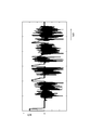
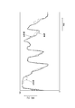
- FIG. 9 shows, as an example of time variation of current, time variation of current when the battery 4 is mounted on an electric vehicle and a running experiment is performed.
- the observer used for the SOC estimation in this example was designed so that G (L) satisfies the expressions (53) and (54) at the same time.
- the observer used for the SOC estimation of the present embodiment was designed in consideration of both the attenuation degree constraint and the L 2 gain constraint.
- SOC estimation according to the comparative example SOC estimation using an observer designed so that G (L) satisfies Expression (53) was performed.
- Observer used in SOC estimation according to the comparative example without considering the L 2 gain-constrained, which is designed in consideration of only the attenuation restrictions.
- the SOC of the battery 4 was estimated using the observer designed in each of the example and the comparative example.
- the horizontal axis and the vertical axis indicate time and SOC, respectively.
- the true value of the SOC is indicated by a broken line.
- the true value of the SOC is a value calculated by a method such as integrating the input current to the battery 4.
- the estimated SOC value according to the embodiment is indicated by a solid line.
- the estimated value of the SOC according to the comparative example is indicated by a one-dot chain line.
- the estimated value of the SOC according to the example is close to the true value of the SOC as compared with the estimated value of the SOC according to the comparative example.
- the estimation error of the SOC using the observer of the example is smaller than the estimation error of the SOC using the observer of the comparative example.
- the SOC estimation error is the difference between the estimated SOC value and the true SOC value.
- the horizontal axis and the vertical axis indicate time and SOC estimation errors, respectively.
- the RMSE of the SOC estimation error using the observer according to the comparative example was 4.5%.
- the RMSE of the SOC estimation error using the observer according to the example was 1.9%.
- the observer is designed in consideration of predetermined constraint conditions including the attenuation constraint and the L 2 gain constraint, so that the estimation accuracy of the SOC is improved. It can be improved.
- SYMBOLS 1 Charge rate estimation apparatus 2 Current sensor 3 Voltage sensor 4 Battery 5 Power supply device 10 Control part 20 Memory
Landscapes
- Engineering & Computer Science (AREA)
- Manufacturing & Machinery (AREA)
- Chemical & Material Sciences (AREA)
- Chemical Kinetics & Catalysis (AREA)
- Electrochemistry (AREA)
- General Chemical & Material Sciences (AREA)
- Physics & Mathematics (AREA)
- General Physics & Mathematics (AREA)
- Power Engineering (AREA)
- Secondary Cells (AREA)
- Charge And Discharge Circuits For Batteries Or The Like (AREA)
- Tests Of Electric Status Of Batteries (AREA)
Abstract
充電率推定装置(1)は、バッテリ(4)のモデルに基づくオブザーバを用いて、バッテリ(4)の充電率を推定し、モデルは、ヒステリシス特性を含む。
Description
本出願は、日本国特許出願2016-215476号(2016年11月2日出願)の優先権を主張するものであり、当該出願の開示全体を、ここに参照のために取り込む。
本発明は、充電率推定装置及び充電率推定方法に関する。
バッテリの充電率と開回路電圧との間の関係にヒステリシスを有するバッテリの充電率を推定する装置が知られている(例えば特許文献1等)。
バッテリの充電率は、バッテリモデルに基づいて推定されうる。バッテリの充電率と開回路電圧との間の関係にヒステリシスを有するバッテリにおいて、バッテリモデルを表すパラメータは変化しやすい。バッテリモデルを表すパラメータの変化によるパラメータの誤差は、バッテリの充電率の推定精度を低下させうる。
かかる事情に鑑みてなされた本発明の目的は、バッテリの充電率の推定精度を向上させることができる充電率推定装置及び充電率推定方法を提供することにある。
上記課題を解決するために、第1の観点に係る充電率推定装置は、バッテリのモデルに基づくオブザーバを用いて、前記バッテリの充電率を推定する。前記モデルは、ヒステリシス特性を含む。
上記課題を解決するために、第2の観点に係る充電率推定方法は、バッテリのモデルに基づくオブザーバを用いて、前記バッテリの充電率を推定するステップを含む。前記モデルは、ヒステリシス特性を含む。
第1の観点に係る充電率推定装置によれば、バッテリの充電率の推定精度が向上されうる。
第2の観点に係る充電率推定方法によれば、バッテリの充電率の推定精度が向上されうる。
本開示の一実施形態に係る充電率推定装置は、電気自動車又はハイブリッド電気自動車などの車両に搭載されてよい。充電率推定装置は、車両のバッテリの充電率を推定してよい。車両には、車両を駆動する電気モータ、バッテリ、これらのコントローラなどが搭載される。バッテリは、放電して電気モータへ電力を供給したり、制動時に電気モータから回生充電したり、地上充電設備から充電したりする。充電率推定装置は、バッテリに流れる充放電電流とバッテリの端子電圧とに基づいて、バッテリの充電率を推定してよい。
[機能ブロック]
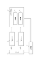
図1に示されるように、充電率推定装置1は、電流センサ2及び電圧センサ3を介してバッテリ4に接続される。充電率推定装置1は、電流センサ2又は電圧センサ3を含んでよい。充電率推定装置1は、電源装置5に接続されてよい。充電率推定装置1は、電源装置5からバッテリ4に対して充放電電流を入力してよい。電源装置5は、例えば電流源であってよい。充電率推定装置1は、電源装置5を含んでよい。
図1に示されるように、充電率推定装置1は、電流センサ2及び電圧センサ3を介してバッテリ4に接続される。充電率推定装置1は、電流センサ2又は電圧センサ3を含んでよい。充電率推定装置1は、電源装置5に接続されてよい。充電率推定装置1は、電源装置5からバッテリ4に対して充放電電流を入力してよい。電源装置5は、例えば電流源であってよい。充電率推定装置1は、電源装置5を含んでよい。
電流センサ2は、バッテリ4に対する充放電電流を検出する。本実施形態において、充放電電流は、時刻(t)の関数であるu(t)で表されると仮定する。電流センサ2は、検出した充放電電流を充電率推定装置1に対して出力する。
電圧センサ3は、バッテリ4の端子電圧を検出する。本実施形態において、端子電圧は、時刻(t)の関数であるy(t)で表されると仮定する。電圧センサ3は、検出した端子電圧を充電率推定装置1に対して出力する。
バッテリ4は、例えば二次電池であってよい。二次電池は、リチャージャブル・バッテリともいう。バッテリ4は、本実施形態においてリチウム・イオン・バッテリであると仮定する。バッテリ4は、他の種類のバッテリであってよい。
充電率推定装置1は、制御部10と、記憶部20とを備える。制御部10は、充電率推定装置1の各構成部を制御する。制御部10は、例えばプロセッサ又はマイクロコンピュータ等で構成されてよい。記憶部20は、例えば半導体メモリ又は磁気記憶装置等で構成されてよい。制御部10は、充電率推定装置1で取り扱われるデータ又は情報等を記憶部20に格納してよい。
制御部10は、電流センサ2及び電圧センサ3から、バッテリ4の充放電電流及び端子電圧をそれぞれ取得する。制御部10は、バッテリ4の充放電電流及び端子電圧に基づいて、バッテリ4の内部状態を推定してよい。
バッテリ4の内部状態は、バッテリ4の開回路電圧と、バッテリ4の内部で発生する過電圧とをパラメータとして含むモデルによって表されうる。開回路電圧は、OCV(Open Circuit Voltage)ともいう。OCVは、バッテリ4の電気化学的平衡状態における電極間の電位差である。OCVは、バッテリ4に充放電電流が流れない場合のバッテリ4の端子電圧に対応する。過電圧は、内部インピーダンスで生じる電圧降下の大きさに対応する。内部インピーダンスは、バッテリ4の内部の電気化学反応の反応速度に応じて決定される。
バッテリ4の内部状態を表すモデルは、図2で示されるようなバッテリ等価回路で近似されうる。バッテリ等価回路で近似されたモデルは、バッテリモデルともいう。バッテリ等価回路の入力は、バッテリ4に流れる充放電電流に対応し、u(t)として示される。図2においてu(t)が付された矢印は、バッテリ4を充電する電流の向きを表す。バッテリ4を充電する電流が流れる場合、u(t)は正の値となると仮定する。バッテリ4から放電電流が流れる場合、u(t)は負の値となると仮定する。バッテリ等価回路の出力は、バッテリ4の端子電圧に対応し、y(t)として示される。図2においてy(t)が付された矢印の先端側の端子は、バッテリ4の正極端子に対応すると仮定する。
バッテリ4のOCVは、バッテリ等価回路において電圧源201で表される。電圧源201が出力する電圧は、時刻の関数であるOCV(t)で表される。OCV(t)は、バッテリ4に充放電電流が流れない場合のバッテリ4の端子電圧に対応する。バッテリ4に充放電電流が流れない場合は、u(t)=0である場合ともいえる。u(t)=0である場合、OCV(t)=y(t)が成立する。
図2のバッテリ等価回路において、バッテリ4の内部インピーダンスは、R0で示される抵抗と、Zw(p)で示されるワールブルグインピーダンスとを直列に接続した回路として表される。R0で示される抵抗は、バッテリ4の電解液内での泳動過程等に起因する抵抗を表す。ワールブルグインピーダンスは、バッテリ4内のイオンの拡散過程等に起因するインピーダンスを表す。バッテリ4の過電圧は、バッテリ等価回路に流れる電流によってバッテリ4の内部インピーダンスで発生する電圧降下として表される。
ワールブルグインピーダンスは、例えば図3Aに示される、R1~Rnとして示される抵抗とC1~Cnとして示されるコンデンサとの並列回路が直列にn個接続されたn次フォスタ型回路として表されてよい。ワールブルグインピーダンスは、例えば図3Bに示される、直列に接続されたn個のコンデンサ(C1~Cn)の間に、R1~Rnとして示されるn個の抵抗のそれぞれが並列に接続されたn次カウエル型回路として表されてよい。ワールブルグインピーダンスは、他の線形伝達関数モデルを用いて表されてもよい。
バッテリ4を近似するバッテリ等価回路のパラメータは、ワールブルグインピーダンスを構成する抵抗の抵抗値と、コンデンサの容量とを含む。バッテリ等価回路のパラメータは、予め設定されてよい。バッテリモデルのパラメータは、制御部10で保持されてよいし、記憶部20に格納されてよい。
制御部10は、バッテリ等価回路のパラメータと、バッテリ4に流れる充放電電流と、バッテリ4の端子電圧とに基づいて、バッテリ4の内部状態を推定する。本実施形態において、制御部10は、バッテリ4の内部状態として、バッテリ4の充電率及び過電圧を推定する。バッテリ4の充電率は、バッテリ4の充電容量に対する充電量の比である。充電率は、SOC(State Of Charge)ともいう。制御部10は、バッテリ4の内部インピーダンスを構成する抵抗の抵抗値及びコンデンサの容量を推定しないと仮定する。制御部10は、内部インピーダンスに含まれる抵抗値及び容量を推定しない構成に限られない。制御部10は、内部インピーダンスに含まれる抵抗値及び容量を推定するように構成されてよい。
制御部10は、バッテリ4のOCV及び過電圧を推定してよい。この場合、制御部10は、バッテリ4のOCVに基づいて、バッテリ4のSOCを推定しうる。
バッテリ4のOCVは、SOCの関数として表されうる。SOCとOCVとの間の関係は、SOC-OCV特性といわれる。SOC-OCV特性は、例えば図4に示されるグラフで表されうる。図4の横軸及び縦軸はそれぞれ、SOC及びOCVを示す。SOC-OCV特性は、予め実験等によって求められうる。制御部10は、バッテリ4のSOC-OCV特性と、バッテリ4のSOCの推定値とに基づいて、バッテリ4のOCVを推定しうる。
[ヒステリシス特性]
SOC-OCV特性は、ヒステリシス特性を有することがある。ヒステリシス特性を有するSOC-OCV特性は、充電時の特性と放電時の特性とが異なる。ヒステリシス特性を有するSOC-OCV特性は、例えば図5のように示される。図5の横軸及び縦軸はそれぞれ、SOC及びOCVを示す。図5では、バッテリ4の充電時のSOC-OCV特性を示す充電SOC-OCV特性501は、破線で示される。バッテリ4の放電時のSOC-OCV特性を示す放電SOC-OCV特性502は、一点鎖線で示される。
SOC-OCV特性は、ヒステリシス特性を有することがある。ヒステリシス特性を有するSOC-OCV特性は、充電時の特性と放電時の特性とが異なる。ヒステリシス特性を有するSOC-OCV特性は、例えば図5のように示される。図5の横軸及び縦軸はそれぞれ、SOC及びOCVを示す。図5では、バッテリ4の充電時のSOC-OCV特性を示す充電SOC-OCV特性501は、破線で示される。バッテリ4の放電時のSOC-OCV特性を示す放電SOC-OCV特性502は、一点鎖線で示される。
充電SOC-OCV特性501及び放電SOC-OCV特性502は、SOC-OCV特性のループを形成する。充電SOC-OCV特性501及び放電SOC-OCV特性502によって形成されるSOC-OCV特性のループは、メジャーループともいう。メジャーループは、バッテリ4に対する充放電の実験によって取得されうる。
バッテリ4は、SOCが0%となるまで放電した後に充電されるとは限らない。例えば、バッテリ4は、図5のA点まで放電した後に充電されることによって、A点からB点に至る経路で示されるSOC-OCV特性を示しうる。バッテリ4は、SOCが100%となるまで充電された後に放電するとは限らない。例えば、バッテリ4は、図5のC点まで充電された後に放電することによって、C点からD点に至る経路で示されるSOC-OCV特性を示しうる。例えば、A点、B点、C点、D点及びA点の順に結ばれる経路で示される、メジャーループよりも小さいSOC-OCV特性のループは、マイナーループともいう。マイナーループは、メジャーループとは異なり、事実上無限に存在しうる。マイナーループは、メジャーループと比較して、事前の実験によって取得されにくい。
図5において実線で示されるSOC-OCV特性500は、充電SOC-OCV特性501と放電SOC-OCV特性502との平均値に対応する。SOC-OCV特性500は、充電SOC-OCV特性501と放電SOC-OCV特性502との平均値に限られない。SOC-OCV特性500は、充電SOC-OCV特性501と放電SOC-OCV特性502との間に含まれるグラフであってよい。
SOC-OCV特性500と、メジャーループとの間のOCVの差は、ヒステリシス電圧ともいう。ヒステリシス電圧は、h(t)と表されると仮定する。ヒステリシスを有するSOC-OCV特性は、事実上無限に存在しうるマイナーループで表される代わりに、ヒステリシス電圧を含む、次の式(1)で表されうる。

fOCV(・)は、SOC-OCV特性500を表す関数である。
SOC-OCV特性が式(1)のように表されることで、制御部10がバッテリ4の内部状態を推定する際にh(t)をあわせて推定することによって、SOCとOCVとの間の変換の精度が高められうる。SOC-OCV特性が式(1)のように表される場合、バッテリ等価回路は、図6のように表される。図6のバッテリ等価回路は、ヒステリシス電圧を表すh(t)が追加された点、及び、電圧源201の出力電圧がfOCV(SOC(t))と表される点で、図2のバッテリ等価回路と異なる。
本実施形態では、ワールブルグインピーダンスは、図3Aに示されるフォスタ型回路で表されると仮定する。この場合、バッテリ等価回路は、図7のように表される。図7のバッテリ等価回路は、Zw(p)がフォスタ型回路に置き換えられた点で、図6のバッテリ等価回路と異なる。vk(t)は、Ckとして示される容量で生じる電圧降下を表す。kは、1~nの整数である。
ヒステリシス現象を表すモデルの一つであるPlettによるヒステリシスモデルによれば、h(t)の挙動は、次の式(2)によって表される。

γは、ヒステリシスモデルの電圧降下の速さを表す。mは、ヒステリシス電圧の最大値を表す。Plettによるヒステリシスモデルについては、例えば、以下の文献が参照されうる。
G. L. Plett: "Extended Kalman filtering for battery management systems of LiPB-based HEV battery packs Part 2. Modeling and identification", Journal of Power Sources 134 (2004) 262-276
G. L. Plett: "Extended Kalman filtering for battery management systems of LiPB-based HEV battery packs Part 2. Modeling and identification", Journal of Power Sources 134 (2004) 262-276
時刻(t)におけるバッテリ4のSOC(t)は、以下の式(3)によって算出されうる。t0は、測定開始時刻を表す。式(3)の右辺第2項の積分は、充放電電流を積算して算出される、バッテリ4に出入りする電荷量を表す。

過電圧は、バッテリ4の内部インピーダンスと、バッテリ4の充放電電流とに基づいて、以下の式(4)のように表される。

η(t)は、過電圧を表す。Gη(p)は、内部インピーダンスを表し、R0とZw(p)との和である。
ワールブルグインピーダンスがフォスタ型回路である場合、Zw(p)は、以下の式(5)のように表される。

ただし、

である。Rdは、拡散抵抗を表す。Cdは、拡散容量を表す。
図7のバッテリ等価回路の出力に対応するy(t)は、次の式(7)で表される。

図7のバッテリ等価回路で表されるバッテリモデルは、充放電電流を入力とし、端子電圧を出力とする、入出力システムによって表される。入出力システムは、単にシステムともいう。入出力システムは、次の式(8)及び(9)によって示される状態空間として表されうる。

状態空間は、システムの状態変数を座標軸として表される空間である。式(8)は、入力と状態変数との関係を表す状態方程式である。式(9)は、状態変数と出力との関係を表す出力方程式である。
式(8)のA(u(t))は、実数空間の(n+2)×(n+2)次の行列であり、以下の式(10)で表される。diagは、対角行列を出力する関数である。

A(u(t))は、システム行列ともいう。システム行列は、システムの特性の少なくとも一部を表す。式(8)のシステム行列は、システムへの入力を示すu(t)に依存する。よって、式(8)及び(9)で表されるシステムは、パラメータ可変システムであるともいえる。パラメータ可変システムは、PV(Parameter Varying)システムともいう。言い換えれば、図7のバッテリモデルで表されるバッテリ4のモデルは、PVシステムによって表されうる。
式(8)のb及び式(9)のcはそれぞれ、実数空間の(n+2)次の列ベクトルを表し、以下の式(11)及び(12)で表される。Tは、転置行列を表す。

式(8)及び(9)のx(t)は、状態変数であり、以下の式(13)で表される。

[システムの内部状態推定]
本実施形態に係る充電率推定装置1は、バッテリ4のモデルを表すPVシステムにおいて、状態変数を推定することによって、バッテリ4の内部状態を推定しうる。制御部10は、電流センサ2から取得した充放電電流をバッテリ4のモデルに入力し、端子電圧の推定値を算出する。制御部10は、端子電圧の推定値と実際の端子電圧との差を、バッテリ4のモデルにフィードバックし、バッテリ4のSOCを逐次推定する。
本実施形態に係る充電率推定装置1は、バッテリ4のモデルを表すPVシステムにおいて、状態変数を推定することによって、バッテリ4の内部状態を推定しうる。制御部10は、電流センサ2から取得した充放電電流をバッテリ4のモデルに入力し、端子電圧の推定値を算出する。制御部10は、端子電圧の推定値と実際の端子電圧との差を、バッテリ4のモデルにフィードバックし、バッテリ4のSOCを逐次推定する。
本実施形態において、バッテリ4のモデルを表すPVシステムは、線形パラメータ可変システムであると仮定する。線形パラメータ可変システムは、LPV(Linear Parameter Varying)システムともいう。LPVシステムに関する以下の説明は、バッテリ4のモデルを表すシステムに限定されるものではない。
LPVシステムは、以下の式(14)~(18)に示される状態空間として表されうる。式(16)~(18)に示されるように、システム行列としてのAは、ポリトープ形式で表されうる。ポリトープ形式は、関数を一次結合で表す形式である。一次結合は、線形結合ともいう。

式(14)は、システムへの入力とシステムの内部状態を表す状態変数との関係を表す状態方程式である。式(15)は、状態変数とシステムからの出力との関係を表す出力方程式である。x(t)は、実数空間のn次の列ベクトルであり、状態変数を表す。u(t)は、実数空間のnu次の列ベクトルであり、システムへの入力を表す。y(t)は、実数空間のny次の列ベクトルであり、システムからの出力を表す。n、nu及びnyはそれぞれ、状態、入力及び出力の信号のサイズに応じて設定される。A(θ(t))、B及びCとして表される行列のサイズは、各信号のサイズに応じて設定される。
式(14)及び(15)で表されるシステムへの入力であるu(t)は、ベクトルであり、太字で表記される。式(8)及び(9)で表されるシステムへの入力であるu(t)は、スカラーであり、細字で表記される。以下、発明の詳細な説明の文中で区別するために、ベクトルを表すu(t)は、以下u→(t)と表す。x(t)及びy(t)についても同様に、ベクトルを表すx(t)及びy(t)はそれぞれ、以下x→(t)及びy→(t)と表す。
式(14)~(18)で表されるLPVシステムにおいて、正数であるa及びρに対して正定値行列Xが存在し、以下の式(19)で示される線形行列不等式が成り立つと仮定する。線形行列不等式は、LMI(Linear Matrix Inequality)ともいう。正定値行列は、正定行列ともいう。

式(19)で、Iは単位行列を表す。
式(19)で示されるLMIが成り立つ場合、式(14)~(18)で表されるLPVシステムにおける自由応答及び入出力応答は、以下の式(20)及び(21)を満たす。

||・||で示される記号は、ノルムを表す。信号のノルムは、信号の大きさを表す。例えば||x(t)||は、x(t)の大きさを表す。||・||2で示される記号は、L2ノルムを表す。L2ノルムは、信号に含まれる成分を二乗平均した値の平方根として算出される。L2ノルムは、ノルムの一種である。式(21)でL2と表される記号は、L2空間を示す。式(21)で、u→は、L2空間の元である。
式(19)が成り立つ場合に式(20)及び(21)が満たされることは、定理として与えられる。式(19)~(21)で示される定理は、第1定理ともいう。
本実施形態に係る充電率推定装置1は、システムの状態変数及びシステムからの出力を推定する。推定値と真値との間には、誤差が発生しうる。推定値と真値との間に生じる誤差は、推定誤差ともいう。システムの入力には、外乱が加わりうる。入力に加わった外乱によって、状態変数及び出力の推定誤差が大きくなりうる。
システムの入力に外乱が加わる場合、システムが以下の式(22)~(24)で表されると仮定する。

x→(t)、u→(t)及びy→(t)はそれぞれ、式(14)及び(15)と同様に、システムの状態変数、システムへの入力及びシステムからの出力を表す。z(t)は、実数空間のnz次の列ベクトルであり、システムの評価出力を表す。システムの評価出力は、システムからの出力のうち、特に注目して評価する対象となる出力を含む。評価は、外乱抑制性能又は即応性等について実行されてよい。ベクトルを表すz(t)は、以下z→(t)と表す。w(t)は、実数空間のnw次の列ベクトルであり、システムへの入力に加わる外乱を表す。ベクトルを表すw(t)は、以下w→(t)と表す。nz及びnwはそれぞれ、評価出力及び外乱の信号のサイズに応じて設定される。A(θ(t))は、式(16)~(18)で与えられる。B1、B2、C1、C2及びDとして表される係数行列のサイズは、状態変数、入力、出力、評価出力及び外乱の信号のサイズに応じて設定される。
式(22)は、外乱が加わったシステムへの入力とシステムの内部状態を表す状態変数との関係を表す状態方程式である。式(23)は、状態変数及びシステムへの入力とシステムからの出力との関係を表す出力方程式である。式(24)は、状態変数とシステムの評価出力との関係を表す評価出力方程式である。
式(22)~(24)において、状態変数、出力及び評価出力をそれぞれ推定値に置き換えることで、式(25)~(27)が導かれる。状態変数、出力及び評価出力の推定値はそれぞれ、x、y及びzの上に記号^を付して表される。

以下、x→(t)、y→(t)及びz→(t)の上に記号^を付した項は、x→^(t)、y→^(t)及びz→^(t)とも表す。
状態変数の推定誤差は、以下の式(28)で表される。状態変数の推定誤差は、x→(t)の上に記号~を付して表される。

以下、x→(t)の上に記号~を付した項は、x→~(t)とも表す。
式(28)の両辺を時刻(t)で微分した式に、式(22)及び(25)を適用することによって、以下の式(29)が導かれる。

式(29)において、A(θ(t))が安定である場合、状態変数の推定誤差は、時刻の経過に応じて収束しうる。言い換えれば、システム行列が安定であるか否かに応じて、推定誤差が収束するか否かが決定されうる。
状態変数、出力及び評価出力の推定値を含む式として、式(25)の代わりに、以下の式(30)が仮定されうる。

式(30)の右辺第3項は、出力の推定誤差が状態方程式にフィードバックされることを表す。式(30)の右辺第3項に式(23)及び(26)を適用することで、以下の式(31)が導かれる。

式(28)の両辺を時刻(t)で微分した式に、式(22)、(30)及び(31)を適用することによって、以下の式(32)が導かれる。

式(32)において、A(θ(t))-LCが安定となるように、Lが設定されうる。言い換えれば、システム行列が安定であるか否かにかかわらず、推定誤差が収束するようなLが設定されうる。
式(30)、(26)及び(27)で構成される式は、システムに対するオブザーバともいう。オブザーバは、状態推定器ともいう。オブザーバは、状態変数の少なくとも一部を直接観測できない場合に、入力と出力とに基づいて、直接観測できない状態変数を推定する機構のことをいう。モデルを表すシステムに対するオブザーバは、モデルに基づくオブザーバともいう。式(30)のLは、オブザーバゲインともいう。Lを設定又は決定することは、オブザーバゲインの設計ともいう。
式(22)~(24)、並びに、式(30)、(26)及び(27)に基づいて、状態変数、出力及び評価出力の推定誤差はそれぞれ、以下の式(33)~(35)で表される。出力及び評価出力の推定誤差はそれぞれ、y及びzの上に記号~を付して表される。以下、y及びzの上に記号~を付した項は、y~及びz~とも表す。

式(33)~(35)に示される、状態変数、出力及び評価出力の推定誤差の関係は、偏差系ともいう。オブザーバゲインは、システムの初期状態で存在する状態変数の推定誤差の減衰の速度を示す減衰度性能、又は、評価出力の推定誤差に対する外乱の影響を低減させる性能を有するように設計されうる。
オブザーバゲインは、種々の方法で設計されうる。例えば、正数であるa及びρに対して、正定値行列Xと行列Yとが存在し、以下の式(36)で示されるLMIが成立すると仮定する。

オブザーバゲインが以下の式(37)に基づいて設計されると仮定する。

式(36)で示されるLMIが成立し、且つ、オブザーバゲインが式(37)に基づいて設計される場合、式(33)~(35)で示される偏差系に対する自由応答は、以下の式(38)を満たす。

システムの初期状態は、時刻(t)が0である場合のシステムの状態である。x→~(0)は、システムの初期状態で存在する状態変数の推定誤差を表す。システムの初期状態で存在する状態変数の推定誤差は、状態推定値の初期値誤差ともいう。aは、状態推定値の初期値誤差が減衰する速度を表し、減衰度ともいう。bは、適宜定められうる係数である。式(38)は、状態変数の推定誤差の大きさが所定の速度以下で減衰しうることを示す。
式(36)で示されるLMIが成立し、且つ、オブザーバゲインが式(37)に基づいて設計される場合、式(33)~(35)で示される偏差系に対する入出力応答は、以下の式(39)を満たす。

ρは、適宜定められうる係数であり、評価出力が外乱から受ける影響の度合いを示す。式(39)は、評価出力が外乱に対して所定の比率未満に低減されうることを示す。
式(36)が成立し、且つ、オブザーバゲインが式(37)に基づいて設計される場合に式(38)及び(39)が満たされることは、第1定理に基づいて導かれる定理として与えられる。式(36)~(39)で示される定理は、第2定理ともいう。
[バッテリモデルに対するオブザーバの設計]
本実施形態に係る充電率推定装置1は、システムに対するオブザーバを適宜設計することによって、システムの状態変数の推定誤差を所定の速度以上で減衰させうる。本実施形態に係る充電率推定装置1は、システムに対するオブザーバを適宜設計することによって、評価出力の推定誤差に対する外乱の影響を低減しうる。
本実施形態に係る充電率推定装置1は、システムに対するオブザーバを適宜設計することによって、システムの状態変数の推定誤差を所定の速度以上で減衰させうる。本実施形態に係る充電率推定装置1は、システムに対するオブザーバを適宜設計することによって、評価出力の推定誤差に対する外乱の影響を低減しうる。
バッテリ4のモデルに対応するシステムは、式(8)~(13)で示されうる。バッテリ4のモデルにヒステリシスモデルが含まれる場合、ヒステリシスモデルのパラメータの不確かさに起因する外乱が、システムへの入力に加わりうる。例えば、式(2)にヒステリシスモデルのパラメータとして含まれるm及びγは、真値に対するモデル化誤差を有しうる。m及びγのノミナル値がヒステリシスモデルのパラメータであると仮定されてよい。m及びγのノミナル値はそれぞれ、m及びγとして想定される値である。ノミナル値がヒステリシスモデルのパラメータとして仮定される場合、システムを表す式(8)及び(9)を変形して、以下の式(40)及び(41)が導かれる。式(41)は、式(9)と同じ式である。

式(40)のw(t)は、ヒステリシスモデルのパラメータの不確かさに起因する外乱を表す。w(t)は、以下の式(42)で表される。

sgn(・)は、符号関数を表す。符号関数は、入力値が正の値である場合に1を出力し、入力値が負の値である場合に-1を出力し、入力値が0である場合に0を出力する関数である。Δmは、mの真値とノミナル値との差を表す。Δγは、γの真値とノミナル値との差を表す。
式(40)及び(41)に含まれるu(t)、y(t)及びw(t)はそれぞれ、スカラーを表し、u→(t)、y→(t)及びw→(t)と区別される。
式(40)のfは、以下の式(43)で表される。

fが式(43)で表される場合、式(13)及び(40)によれば、外乱を表すw(t)の成分は、x(t)に含まれる成分のうちh(t)にのみ加わる。
式(40)及び(41)は、ヒステリシスモデルのパラメータの誤差を考慮した、バッテリ4のシステムを表す。式(40)及び(41)で示されるシステムに対して、以下の式(44)及び(45)に示されるオブザーバが構成されうる。

x→^(t)及びy^(t)はそれぞれ、x→(t)及びy(t)の推定値を表す。SOCの推定値は、SOCの上に記号^を付して表される。SOCの上に記号^を付した項は、SOC^とも表す。Lは、実数空間の(n+2)次の列ベクトルであり、オブザーバゲインを表す。
SOCの推定誤差が十分に小さいと仮定した場合、fOCV(・)を線形化して、以下の式(46)が導かれる。

αは、適宜定められうる定数である。
状態変数の推定誤差は、以下の式(47)で表されると仮定する。

式(40)~(47)に基づいて、以下の式(48)が導かれる。

clは、以下の式(49)で表される。

システムの評価出力を決定する評価出力方程式として、以下の式(50)が導入される。

czは、以下の式(51)で表される。

czは、状態変数の推定誤差を評価出力に反映させる際に、状態変数の推定誤差に含まれる成分に重み付けを与える。
式(50)及び(51)によれば、状態変数のうちSOCの成分だけが評価出力に反映される。言い換えれば、評価出力は、SOCの推定誤差として算出される。よって、z(t)は、以下の式(52)で表される。

式(48)及び(50)は、入力をw(t)とし、出力をz(t)とするシステムを表す。以下、式(48)及び(50)で表されるシステムは、G(L)と表される。G(L)は、システム行列がu(t)に依存するLPVシステムである。
G(L)がBIBO(Bounded Input Bounded Output)安定であり、且つ、G(L)の入出力ゲインが十分に小さい場合、w(t)の入力にかかわらず、SOCの推定誤差が小さくされうる。BIBO安定は、システムへの入力が有限値である場合、システムからの出力が有限値であることを意味する。
BIBO安定であること、及び、G(L)の入出力ゲインが十分に小さいことは、以下の式(53)及び(54)で表される制約とみなされうる。

式(53)は、システムの初期状態における状態変数の推定誤差に対する、G(L)の自由応答が満たすべき減衰度制約を示す式である。aは、G(L)の自由応答の減衰度を示す正数である。bは、適宜定められうる係数である。式(53)は、式(38)に対応する式である。
式(54)は、G(L)のL2ゲインが満たすべきL2ゲイン制約を示す式である。G(L)のL2ゲインは、G(L)の評価出力信号のL2ノルムとG(L)の入力信号のL2ノルムとの比の上界として定義される。ρは、G(L)のL2ゲインの上界の範囲を指定する正数である。G(L)のL2ゲインは、システムが表すモデルに含まれるパラメータの誤差に対する、評価出力の大きさの比を意味する。
本実施形態においては、式(53)及び(54)で示される2つの制約が同時に満たされるように、オブザーバゲインが設計されうる。言い換えれば、オブザーバゲインは、所定の制約条件を満たすように設定されうる。所定の制約条件は、減衰度制約及びL2ゲイン制約を含む。
例えば、式(53)のaは、バッテリ4のSOCの推定誤差が所定の時間内に収束するように設定されてよい。SOCの推定誤差が所定の時間内に収束するようにaが設定される場合、さらに式(54)が満たされるように、ρが最小化されてよい。
バッテリ4の充放電電流の大きさは、|u(t)|と表される。|u(t)|の最大値及び最小値が既知である場合、バッテリ4のモデルを表すシステムのシステム行列は、以下の式(55)~(58)で示されるポリトープ形式で表されうる。

uminは、|u(t)|の最小値である。umaxは、|u(t)|の最大値である。θ1(u(t))及びθ2(u(t))は、ポリトープ形式のパラメータである。
システム行列は、式(44)及び式(45)で表されるオブザーバのパラメータの少なくとも一部を構成する。システム行列がポリトープ形式で表されることによって、オブザーバのパラメータの少なくとも一部がポリトープ形式で表される。
A(u(t))がポリトープ形式で表され、且つ、正数であるa及びρに対して正定値行列X及び行列Yが存在し、以下の式(59)及び(60)で示されるLMIが成立すると仮定する。

式(59)及び式(60)において、以下の式(61)が成り立つ。

第2定理によれば、G(L)が式(53)及び(54)を同時に満たすようなオブザーバゲインは、以下の式(62)によって設計される。

式(59)及び(60)で示されるLMIが成立し、且つ、ρが最小化されるように、正定値行列X及び行列Yが算出されうる。このように算出された正定値行列X及び行列Yに基づいて、より小さいL2ゲインを有するオブザーバゲインが設計されうる。バッテリ4のバッテリモデルにおいて、G(L)のL2ゲインは、バッテリモデルに含まれるパラメータの誤差に対する、バッテリ4の充電率の推定誤差の大きさの比である。より小さいL2ゲインを有するオブザーバゲインが設計されることによって、バッテリモデルに含まれるパラメータの誤差に応じたバッテリ4の充電率の推定誤差は、減少されうる。オブザーバゲインがより小さいL2ゲインを有するように設計されたオブザーバは、ロバストオブザーバともいう。
本実施形態に係る充電率推定装置1は、ヒステリシス特性を含むバッテリ4のモデルに基づくオブザーバを用いて、バッテリ4のSOCを推定する。オブザーバを用いることで、ヒステリシス特性の影響等によってバッテリ4のモデルのパラメータの誤差がある場合でも、バッテリ4のSOCの推定精度が向上しうる。また、バッテリモデルのパラメータの逐次推定によってパラメータの誤差を低減させる場合と比較して、充電率推定装置1の計算負荷が軽減されうる。
オブザーバゲインがバッテリ4のモデルに含まれるパラメータの誤差に応じたSOCの推定誤差を減少するように設定されることで、バッテリ4のSOCの推定精度が向上しうる。
オブザーバゲインが所定の制約条件を満たすように設定されることで、バッテリ4のSOCの推定精度が向上しうる。
オブザーバに含まれるパラメータの一部であるシステム行列が式(55)-(58)のようにポリトープ形式で表されることで、オブザーバゲインの算出が容易になりうる。また、オブザーバゲインが所定のLMIを満たすことでも、オブザーバゲインの算出が容易になりうる。
オブザーバゲインが満たす所定のLMIが、パラメータとして、減衰度aを含むことで、パラメータの誤差がSOCの推定値に対して及ぼす影響がより低減されうる。
[充電率推定方法]
本実施形態に係る充電率推定装置1は、図8に示される充電率推定方法によって、バッテリ4のSOCを推定してよい。
本実施形態に係る充電率推定装置1は、図8に示される充電率推定方法によって、バッテリ4のSOCを推定してよい。
制御部10は、バッテリ4のバッテリモデルのパラメータを取得する(ステップS1)。制御部10は、バッテリモデルのパラメータを記憶部20又は外部装置から取得してよい。
制御部10は、バッテリ4のバッテリモデルで表されるシステムに対するオブザーバを取得する(ステップS2)。制御部10は、バッテリモデルのパラメータ、及び、式(62)等に基づいて、オブザーバを設計してよい。制御部10は、予め設計されたオブザーバを記憶部20又は外部装置から取得してよい。
制御部10は、バッテリ4のSOCを推定する(ステップS3)。制御部10は、取得したオブザーバに基づいて、バッテリ4のSOCを推定しうる。このようにすることで、バッテリ4のSOCの推定精度が高められうる。
[充電率推定結果の例]
式(62)等に基づいて設計されたオブザーバゲインを含むオブザーバによって、バッテリ4のSOCが推定されうる。以下、SOCの推定結果の一例の説明において、図9、図10及び図11が参照される。
式(62)等に基づいて設計されたオブザーバゲインを含むオブザーバによって、バッテリ4のSOCが推定されうる。以下、SOCの推定結果の一例の説明において、図9、図10及び図11が参照される。
SOCを推定するために、バッテリ4のバッテリモデルで表されるシステムに対して、図9に示されるように時間変動する電流が入力された。図9には、電流の時間変動の例として、バッテリ4が電気自動車に搭載されて走行実験が行われた際の電流の時間変動が示される。
本実施例のSOC推定に用いられたオブザーバは、G(L)が式(53)及び(54)を同時に満たすように設計された。言い換えれば、本実施例のSOC推定に用いられたオブザーバは、減衰度制約とL2ゲイン制約とをともに考慮して設計された。一方で、比較例に係るSOC推定として、G(L)が式(53)を満たすように設計されたオブザーバを用いたSOC推定が行われた。比較例に係るSOC推定に用いられたオブザーバは、L2ゲイン制約を考慮せずに、減衰度制約のみを考慮して設計された。
図10に示されるように、実施例及び比較例それぞれで設計されたオブザーバを用いて、バッテリ4のSOCが推定された。図10において、横軸及び縦軸はそれぞれ、時刻及びSOCを示す。SOCの真値は、破線で示される。SOCの真値は、バッテリ4への入力電流を積算する等の方法によって算出された値である。実施例に係るSOCの推定値は、実線で示される。比較例に係るSOCの推定値は、一点鎖線で示される。実施例に係るSOCの推定値は、比較例に係るSOCの推定値と比較して、SOCの真値に近い。
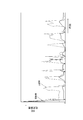
図11に示されるように、実施例のオブザーバを用いたSOCの推定誤差は、比較例のオブザーバを用いたSOCの推定誤差よりも小さい。SOCの推定誤差は、SOCの推定値とSOCの真値との差である。図11において、横軸及び縦軸はそれぞれ、時刻及びSOCの推定誤差を示す。
図11に例示されるSOCの推定誤差のRMSE(Root Mean Square Error)を計算した結果、比較例に係るオブザーバを用いたSOCの推定誤差のRMSEは、4.5%であった。一方で、実施例に係るオブザーバを用いたSOCの推定誤差のRMSEは、1.9%であった。減衰度制約のみを考慮してオブザーバが設計される場合と比較して、減衰度制約及びL2ゲイン制約を含む所定の制約条件を考慮してオブザーバが設計されることによって、SOCの推定精度が向上されうる。
本開示に係る実施形態について諸図面および実施例に基づき説明してきたが、当業者であれば本開示に基づき種々の変形または修正をおこなうことが容易であることに注意されたい。従って、これらの変形または修正は本開示の範囲に含まれることに留意されたい。例えば、各構成部、各ステップなどに含まれる機能などは論理的に矛盾しないように再配置可能であり、複数の構成部およびステップなどを1つに組み合わせたり、或いは分割したりすることが可能である。
1 充電率推定装置
2 電流センサ
3 電圧センサ
4 バッテリ
5 電源装置
10 制御部
20 記憶部
201 電圧源
500 SOC-OCV特性
501 充電SOC-OCV特性
502 放電SOC-OCV特性
2 電流センサ
3 電圧センサ
4 バッテリ
5 電源装置
10 制御部
20 記憶部
201 電圧源
500 SOC-OCV特性
501 充電SOC-OCV特性
502 放電SOC-OCV特性
Claims (12)
- バッテリのモデルに基づくオブザーバを用いて、前記バッテリの充電率を推定し、
前記モデルは、ヒステリシス特性を含む、充電率推定装置。 - 請求項1に記載の充電率推定装置において、
前記オブザーバは、パラメータとしてオブザーバゲインを含み、
前記オブザーバゲインは、前記モデルに含まれるパラメータの誤差に応じた前記充電率の推定誤差を減少させるように設定される、充電率推定装置。 - 請求項2に記載の充電率推定装置において、
前記オブザーバゲインは、所定の制約条件を満たすように設定される、充電率推定装置。 - 請求項3に記載の充電率推定装置において、
前記オブザーバに含まれるパラメータの少なくとも一部は、ポリトープ形式で表され、
前記所定の制約条件は、所定の線形行列不等式で表される、充電率推定装置。 - 請求項3に記載の充電率推定装置において、
前記所定の制約条件は、前記モデルに含まれる状態推定値の初期値誤差を減衰させる速度を指定するパラメータを含む、充電率推定装置。 - 請求項4に記載の充電率推定装置において、
前記所定の制約条件は、前記モデルに含まれる状態推定値の初期値誤差を減衰させる速度を指定するパラメータを含む、充電率推定装置。 - バッテリのモデルに基づくオブザーバを用いて、前記バッテリの充電率を推定するステップを含み、
前記モデルは、ヒステリシス特性を含む、充電率推定方法。 - 請求項7に記載の充電率推定方法において、
前記オブザーバは、パラメータとしてオブザーバゲインを含み、
前記オブザーバゲインを、前記モデルに含まれるパラメータの誤差に応じた前記充電率の推定誤差を減少させるように設定するステップをさらに含む、充電率推定方法。 - 請求項8に記載の充電率推定方法において、
前記オブザーバゲインを設定するステップにおいて、前記オブザーバゲインは、所定の制約条件を満たすように設定される、充電率推定方法。 - 請求項9に記載の充電率推定方法において、
前記オブザーバに含まれるパラメータの少なくとも一部は、ポリトープ形式で表され、
前記所定の制約条件は、所定の線形行列不等式で表される、充電率推定方法。 - 請求項9に記載の充電率推定方法において、
前記所定の制約条件は、前記モデルに含まれる状態推定値の初期値誤差を減衰させる速度を指定するパラメータを含む、充電率推定方法。 - 請求項10に記載の充電率推定方法において、
前記所定の制約条件は、前記モデルに含まれる状態推定値の初期値誤差を減衰させる速度を指定するパラメータを含む、充電率推定方法。
Priority Applications (2)
| Application Number | Priority Date | Filing Date | Title |
|---|---|---|---|
| CN201780063665.9A CN109844551B (zh) | 2016-11-02 | 2017-10-03 | 观测器增益的设定方法 |
| DE112017005514.8T DE112017005514T5 (de) | 2016-11-02 | 2017-10-03 | Laderatenabschätzeinrichtung und laderatenabschätzverfahren |
Applications Claiming Priority (2)
| Application Number | Priority Date | Filing Date | Title |
|---|---|---|---|
| JP2016215476A JP6869697B2 (ja) | 2016-11-02 | 2016-11-02 | オブザーバゲインの設定方法 |
| JP2016-215476 | 2016-11-02 |
Publications (1)
| Publication Number | Publication Date |
|---|---|
| WO2018083932A1 true WO2018083932A1 (ja) | 2018-05-11 |
Family
ID=62076784
Family Applications (1)
| Application Number | Title | Priority Date | Filing Date |
|---|---|---|---|
| PCT/JP2017/036038 WO2018083932A1 (ja) | 2016-11-02 | 2017-10-03 | 充電率推定装置及び充電率推定方法 |
Country Status (4)
| Country | Link |
|---|---|
| JP (1) | JP6869697B2 (ja) |
| CN (1) | CN109844551B (ja) |
| DE (1) | DE112017005514T5 (ja) |
| WO (1) | WO2018083932A1 (ja) |
Cited By (1)
| Publication number | Priority date | Publication date | Assignee | Title |
|---|---|---|---|---|
| CN113728242A (zh) * | 2019-05-08 | 2021-11-30 | 特艾斯技术有限责任公司 | 对可充电电池中的析锂进行表征 |
Families Citing this family (4)
| Publication number | Priority date | Publication date | Assignee | Title |
|---|---|---|---|---|
| WO2018159843A1 (ja) * | 2017-03-03 | 2018-09-07 | カルソニックカンセイ株式会社 | 充電率推定装置及び充電率推定方法 |
| JP7203375B2 (ja) * | 2018-11-20 | 2023-01-13 | マレリ株式会社 | 充電率推定装置及び充電率推定方法 |
| KR102599803B1 (ko) * | 2020-12-10 | 2023-11-09 | 한국에너지기술연구원 | Soc추정을 통해 배터리 상태를 진단하는 방법 및 장치 |
| DE102021005322A1 (de) | 2021-10-26 | 2021-12-16 | Daimler Ag | Verfahren zum Bestimmen eines aktuellen Ladezustands eines elektrischen Energiespeichers, sowie Implementierung im Energiemanagementsystem |
Citations (1)
| Publication number | Priority date | Publication date | Assignee | Title |
|---|---|---|---|---|
| JP2011033453A (ja) * | 2009-07-31 | 2011-02-17 | Honda Motor Co Ltd | 蓄電装置の内部抵抗検出装置および開路電圧検出装置および残容量検出装置 |
Family Cites Families (5)
| Publication number | Priority date | Publication date | Assignee | Title |
|---|---|---|---|---|
| CN104007395B (zh) * | 2014-06-11 | 2016-08-24 | 北京交通大学 | 锂离子电池荷电状态与参数自适应联合估计方法 |
| US10408880B2 (en) * | 2014-08-19 | 2019-09-10 | Fca Us Llc | Techniques for robust battery state estimation |
| JP6450565B2 (ja) | 2014-10-31 | 2019-01-09 | カルソニックカンセイ株式会社 | バッテリのパラメータ推定装置 |
| JP6498034B2 (ja) | 2015-05-19 | 2019-04-10 | キヤノン株式会社 | インクジェット記録装置、制御方法およびプログラム |
| CN105353313B (zh) * | 2015-09-28 | 2020-07-28 | 欣旺达电子股份有限公司 | 电池荷电状态的估算方法和装置 |
-
2016
- 2016-11-02 JP JP2016215476A patent/JP6869697B2/ja active Active
-
2017
- 2017-10-03 WO PCT/JP2017/036038 patent/WO2018083932A1/ja active Application Filing
- 2017-10-03 DE DE112017005514.8T patent/DE112017005514T5/de active Pending
- 2017-10-03 CN CN201780063665.9A patent/CN109844551B/zh active Active
Patent Citations (1)
| Publication number | Priority date | Publication date | Assignee | Title |
|---|---|---|---|---|
| JP2011033453A (ja) * | 2009-07-31 | 2011-02-17 | Honda Motor Co Ltd | 蓄電装置の内部抵抗検出装置および開路電圧検出装置および残容量検出装置 |
Non-Patent Citations (3)
| Title |
|---|
| FENG, X. Y. ET AL.: "A battery model including hysteresis for State-of-Charge estimation in Ni-MH battery", VEHICLE POWER AND PROPULSION CONFERENCE, 18 November 2008 (2008-11-18), XP031363129, Retrieved from the Internet <URL:http://ieeexplore.ieee.org/document/4677449> [retrieved on 20171220] * |
| HATTAHA, KENICHI ET AL.: "Robust observer design for state-of-charge estimation of rechargeable battery", PROCEEDINGS OF THE JAPAN JOINT AUTOMATIC CONTROL CONFERENCE, 20 December 2017 (2017-12-20), pages 554 - 559, Retrieved from the Internet <URL:http://www.jstage.jst.go.jp/article/jacc/59/0/59-554/_article/-char/ja> * |
| WANG, D. ET AL.: "Dynamic function and control for polytopic system (1st Report, Polytopic observer design by LMI formulation", TRANSACTIONS OF THE JAPAN SOCIETY OF MECHANICAL ENGINEERS (SERIES C, vol. 67, no. 663, 26 February 2008 (2008-02-26), pages 3484 - 3490, XP055501761, Retrieved from the Internet <URL:URL:https://www.jstage.jst.go.jp/article/kikaicl979/67/663/67_663_6484/_article/-har/ja/><DOI:https://doi.org/10.1299/kikaic.67.3484> [retrieved on 20171220] * |
Cited By (1)
| Publication number | Priority date | Publication date | Assignee | Title |
|---|---|---|---|---|
| CN113728242A (zh) * | 2019-05-08 | 2021-11-30 | 特艾斯技术有限责任公司 | 对可充电电池中的析锂进行表征 |
Also Published As
| Publication number | Publication date |
|---|---|
| CN109844551B (zh) | 2021-04-13 |
| DE112017005514T5 (de) | 2019-12-05 |
| CN109844551A (zh) | 2019-06-04 |
| JP2018072265A (ja) | 2018-05-10 |
| JP6869697B2 (ja) | 2021-05-12 |
Similar Documents
| Publication | Publication Date | Title |
|---|---|---|
| WO2018083932A1 (ja) | 充電率推定装置及び充電率推定方法 | |
| KR102150271B1 (ko) | 다수의 옵저버를 갖는 배터리 관리 시스템 | |
| CN106062579B (zh) | 电池状态估计装置以及电池状态估计方法 | |
| Song et al. | Current profile optimization for combined state of charge and state of health estimation of lithium ion battery based on Cramer–Rao bound analysis | |
| EP2852848B1 (en) | Battery system and method with parameter estimator | |
| CN110290972B (zh) | 估计电池单体的充电状态的方法 | |
| US20220365139A1 (en) | Method for estimating an operating parameter of a battery unit | |
| Taborelli et al. | State of charge estimation using extended Kalman filters for battery management system | |
| Xie et al. | Available power prediction limited by multiple constraints for LiFePO4 batteries based on central difference Kalman filter | |
| JP6958965B2 (ja) | バッテリーsoc推定装置及び方法 | |
| CN113728242A (zh) | 对可充电电池中的析锂进行表征 | |
| US20200072146A1 (en) | Control device and control method | |
| JP2017223536A (ja) | 電池状態推定装置および電池状態推定方法 | |
| JP2016090322A (ja) | バッテリのパラメータ推定装置 | |
| WO2018011993A1 (ja) | シミュレーション方法及びシミュレーション装置 | |
| JP2015105875A (ja) | 近似関数作成プログラム、近似関数作成方法、近似関数作成装置および充電率推定プログラム | |
| JP2018009939A (ja) | シミュレーション方法及びシミュレーション装置 | |
| JP2021532370A (ja) | 充電状態推定装置及び方法 | |
| JP7141620B2 (ja) | オブザーバゲインの設定方法 | |
| JP2019100897A (ja) | デバイス状態検知装置、電源システムおよび自動車 | |
| US20210341541A1 (en) | Battery control device | |
| JP2018048913A (ja) | バッテリのパラメータ推定装置及びパラメータ推定方法 | |
| JP7203375B2 (ja) | 充電率推定装置及び充電率推定方法 | |
| JP2018084548A (ja) | 二次電池の状態推定装置及び車両 | |
| JP2018009941A (ja) | 蓄電デバイス容量選択方法 |
Legal Events
| Date | Code | Title | Description |
|---|---|---|---|
| 121 | Ep: the epo has been informed by wipo that ep was designated in this application |
Ref document number: 17867931 Country of ref document: EP Kind code of ref document: A1 |
|
| 122 | Ep: pct application non-entry in european phase |
Ref document number: 17867931 Country of ref document: EP Kind code of ref document: A1 |