WO2018083916A1 - 永久磁石式回転電動機、および、これを用いた圧縮機 - Google Patents
永久磁石式回転電動機、および、これを用いた圧縮機 Download PDFInfo
- Publication number
- WO2018083916A1 WO2018083916A1 PCT/JP2017/034882 JP2017034882W WO2018083916A1 WO 2018083916 A1 WO2018083916 A1 WO 2018083916A1 JP 2017034882 W JP2017034882 W JP 2017034882W WO 2018083916 A1 WO2018083916 A1 WO 2018083916A1
- Authority
- WO
- WIPO (PCT)
- Prior art keywords
- permanent magnet
- rotary electric
- electric motor
- insulating sheet
- stator
- Prior art date
- Legal status (The legal status is an assumption and is not a legal conclusion. Google has not performed a legal analysis and makes no representation as to the accuracy of the status listed.)
- Ceased
Links
Images
Classifications
-
- H—ELECTRICITY
- H02—GENERATION; CONVERSION OR DISTRIBUTION OF ELECTRIC POWER
- H02K—DYNAMO-ELECTRIC MACHINES
- H02K3/00—Details of windings
- H02K3/32—Windings characterised by the shape, form or construction of the insulation
- H02K3/34—Windings characterised by the shape, form or construction of the insulation between conductors or between conductor and core, e.g. slot insulation
Definitions
- the present invention relates to a permanent magnet type rotary electric motor and a compressor using the same.
- Patent Document 1 As a prior art of a permanent magnet type rotating electric machine and a compressor using the same, there is one disclosed in Patent Document 1, for example.
- the electric motor described in Patent Document 1 is described in the abstract of the same document as “at least one end insulating member 20 has a step portion 31 and a notch portion 32 (guide portion) at both ends in the circumferential direction of the first member 30.
- the first winding insulating member 70 is guided by the notch 32 and inserted into the slot 15, and is fixed in the slot 15 by the step portion 31.
- a step is provided in an insulator (“end insulating member 20” in the same document) disposed at both axial ends of the core (“stator core 10” in the same document), and this is provided as a guide portion (“notch” in the same document).
- the interphase insulating sheet (“first winding insulating member 70 ”in the same document) can be easily inserted while guiding, and the effect of improving the assemblability at the time of manufacturing the motor can be obtained. (Fig. 2, Fig. 3, Fig. 5, Fig. Reference, etc.).
- Patent Document 1 As shown in FIG. 2 and FIG. 3 of the same document, a guide portion is required for the insulator, and this portion becomes a thin portion. There is a problem that the sex gets worse. In addition, since the insertability from the guide portion provided in the insulator is improved, the interphase insulating sheet is likely to drop off from the guide portion, and there is a problem that the guide portion causes deterioration of the retainability of the interphase insulating sheet. is there.
- an object of the present invention is to improve the insertability of the interphase insulating sheet and achieve the improved assemblability of the permanent magnet type rotary electric motor without arranging the guide portion in the insulator.
- Another object of the present invention is to improve the reliability of the permanent magnet type rotary electric motor by improving the retainability of the interphase insulating sheet after assembly and making it difficult for the interphase insulating sheet to come off. To do.
- a permanent magnet type rotary electric motor of the present invention comprises a rotor and a stator, and the stator is provided on a substantially annular stator core and an inner peripheral side of the stator core.
- a plurality of slot portions, a plurality of tooth portions provided on the inner peripheral side of the stator core, a plurality of armature windings in which a coil is wound around each tooth portion, and between the armature windings The interphase insulating sheet is disposed and insulates both, and the interphase insulating sheet has a notch on the distal end side in the insertion direction.
- the stator includes a rotor and a stator, and the stator includes a substantially annular stator core, a plurality of teeth provided on an inner peripheral side of the stator core, and an inner peripheral side of the stator core.
- a plurality of slot portions provided in each of the plurality of armature windings in which a coil is wound around each of the tooth portions, and a resin-made interphase insulating sheet disposed between the armature windings to insulate them.
- the interphase insulating sheet has a cross-sectional shape having four or more folds.
- the present invention it is possible to improve the insertability of the interphase insulating sheet and improve the assemblability of the permanent magnet type rotary electric motor.
- the interphase insulating sheet can be made difficult to come off, and the reliability can be improved.
- Sectional view of compressor of one embodiment The enlarged top view of the stator of the rotary electric motor of one Example Part D enlarged view of FIG. 2A
- the perspective view of the phase insulation sheet of one Example The perspective view in the middle of insertion to the stator of the phase insulation sheet of one Example
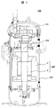
- the compressor 200 of this embodiment is provided with a compression mechanism section 201, a drive shaft 202, and a rotary motor section 203 inside a casing 204 that is also a compression container.
- a power line (not shown) is provided below the unit 203.
- the rotary electric motor unit 203 is a permanent magnet type rotary electric motor composed of a stator 1 on the outer peripheral side and a rotor 8 on the inner peripheral side, and is a drive integrated with the rotor 8 when the rotor 8 is rotated.
- the shaft 202 rotates and the refrigerant is compressed by the compression mechanism 201 at the tip of the drive shaft 202.
- the rotary electric motor unit 203 since the rotary electric motor unit 203 is located inside the casing 204 through which the refrigerant circulates, the components of the rotary electric motor unit 203 are also acted on by the force of the refrigerant flow.
- the interphase insulating sheet 10 to be inserted into the stator 1 is configured as shown in FIGS. 2 to 4, so that even if the flow of the refrigerant acts on the interphase insulating sheet 10, it can withstand this. did.
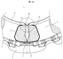
- FIG. 2A is an enlarged top view of the stator 1 of the rotary electric motor unit 203 as viewed from above.
- the slot portion 2 and the teeth portion 5 are provided on the inner peripheral side of the substantially annular stator core 7.
- a plurality of armature windings 6 are formed by winding a coil around each of the teeth portions 5.
- the armature winding 6 and the tooth portion 5 are insulated by a resin slot insulating sheet 3, and the armature windings 6 are insulated by a resin interphase insulating sheet 10.
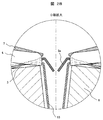
- FIG. 2B is an enlarged view of a portion D in FIG. 2A, and the slot insulating sheet 3 is arranged along the inner surface of the stator core 7 as shown here.
- the slot insulating sheet 3 is a single insulating sheet separated in the vicinity of the center of the slot portion 2, and both ends thereof are bent inward to form a guide portion 3a.
- the interphase insulating sheet 10 is bent outward at both ends, and sandwiched between the respective ends of the insulating sheet 10 by the slot insulating sheet 3 and the armature winding 6, thereby preventing the stator 1 from moving in the radial direction. ing. Further, by disposing the resin insulator 4 above the interphase insulating sheet 10, the interphase insulating sheet 10 is prevented from dropping above the slot portion 2.
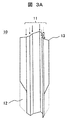
- FIG. 3A is a perspective view of the interphase insulating sheet 10 before being inserted into the stator 1.
- the interphase insulating sheet 10 has notches 12 at both ends in the short direction in order to improve the assemblability when the stator 1 is inserted.
- This notch 12 is arranged only on one side in the longitudinal direction (lower side in FIG. 3A), and the other (upper side in FIG. 3A) is a corner 13 without providing the notch 12. Note that the notch 12 is notched to the vicinity of the fold located at the outermost part at both ends in the short direction.
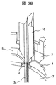
- FIG. 3B is a perspective view showing a state in the middle of inserting the interphase insulating sheet 10 into the stator 1.
- the armature winding 6 is omitted.
- the notch 12 side of the interphase insulating sheet 10 is set as an insertion side when inserting into the stator 1, and the inner peripheral side is set in the width direction. It can be easily inserted into the stator 1 by being inserted into the slot portion 2 along the crushing guide portion 3a.
- the insulator 4 can be easily inserted into the stator 1 without deteriorating the formability by providing the insulator 4 with the guide for inserting the interphase insulating sheet.
- the interphase insulating sheet 10 has a tapered shape. Therefore, the interphase insulating sheet 10 is easy to insert into the slot portion 2, and is pushed in with the tip having the notch 12 inserted. Thus, it is possible to easily guide to the back of the slot portion 2.
- the shape of the notch 12 is not a stepped shape but an inclined shape, it can be easily guided to the back of the slot portion 2 simply by applying a force so as to be inserted into the back as it is after the tip portion is inserted.
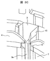
- FIG. 3C is a perspective view showing a state after the interphase insulating sheet 10 is inserted into the stator 1. Also here, the armature winding 6 is omitted.
- FIG. 3C or FIG. 2B after the interphase insulating sheet 10 is inserted, the corners 13 at the upper ends of the interphase insulating sheet 10 are held by the insulator 4 and the slot insulating sheet 3. Even when the refrigerant flow from above acts, the interphase insulating sheet 10 can be prevented from falling off, so that the reliability as an electric motor can be improved.
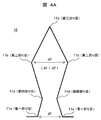
- the interphase insulating sheet 10 of the present embodiment has four or more folds 11 in order to improve reliability and retainability.
- the refrigerant circulates in the periphery of the electric motor or in the slot portion 2 inside, and there is a possibility that the interphase insulating sheet 10 falls off.
- the interphase insulating sheet 10 is thermally deformed along the shape of the slot portion 2 and spreads in the slot portion 2 so that the portion caught by the insulator 4 becomes the slot portion 2. Pulled inward, the interphase insulating sheet 10 becomes easy to drop off.
- the interphase insulating sheet 10 of the present embodiment four or more folds are provided, and the shape is expanded in advance in the slot portion 2 so that the interphase insulating sheet 10 is not easily dropped even if the interphase insulating sheet 10 is thermally deformed.
- the seven-fold interphase insulating sheet 10 shown in the cross-sectional view of FIG. 4A constitutes a corner 13 that is hooked on the insulator 4 by the two first folds 11a of the valley fold, and the circumferential direction between the two first folds 11a.
- the circumferential distance d2 between the two second folds 11b of the mountain fold more than the distance d1
- an extended portion that is hooked on the inner surface of the slot portion 2 is formed.
- the interphase insulating sheet 10 is held on both the insulator 4 side and the slot portion 2 side, and can be prevented from falling off due to the circulation and thermal deformation of the refrigerant.
- the third fold 11c of the mountain fold is provided between the two first folds, and the tip is sharpened, so that the insertion operation is further facilitated, and the valley between each first fold and the second fold is provided.
- the fourth fold line 11d By providing the fourth fold line 11d, the hook on the insulator 4 is further strengthened.
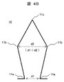
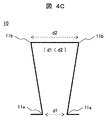
- the extended portion formed between the two second folds 11b can also be formed by a five-fold interphase insulating sheet 10 (FIG. 4B) or a four-fold interphase insulating sheet 10 (FIG. 4C).
- a five-fold interphase insulating sheet 10 FIG. 4B
- a four-fold interphase insulating sheet 10 FIG. 4C
- the extended portion cannot be formed, and the retention on the slot portion 2 side is inferior.
- the assembly including the insertion of the interphase insulating sheet 10 of the permanent magnet type rotary motor into the stator 1 can be improved, and the permanent magnet type rotary motor can be improved.
Landscapes
- Engineering & Computer Science (AREA)
- Power Engineering (AREA)
- Insulation, Fastening Of Motor, Generator Windings (AREA)
Applications Claiming Priority (2)
| Application Number | Priority Date | Filing Date | Title |
|---|---|---|---|
| JP2016215077A JP6578267B2 (ja) | 2016-11-02 | 2016-11-02 | 永久磁石式回転電動機、および、これを用いた圧縮機 |
| JP2016-215077 | 2016-11-02 |
Publications (1)
| Publication Number | Publication Date |
|---|---|
| WO2018083916A1 true WO2018083916A1 (ja) | 2018-05-11 |
Family
ID=62076031
Family Applications (1)
| Application Number | Title | Priority Date | Filing Date |
|---|---|---|---|
| PCT/JP2017/034882 Ceased WO2018083916A1 (ja) | 2016-11-02 | 2017-09-27 | 永久磁石式回転電動機、および、これを用いた圧縮機 |
Country Status (3)
| Country | Link |
|---|---|
| JP (1) | JP6578267B2 (enExample) |
| TW (1) | TWI663814B (enExample) |
| WO (1) | WO2018083916A1 (enExample) |
Cited By (3)
| Publication number | Priority date | Publication date | Assignee | Title |
|---|---|---|---|---|
| DE102019112534A1 (de) * | 2019-05-14 | 2020-11-19 | Hanon Systems | Vorrichtung zum Antreiben eines Verdichters mit einer Isolationsanordnung |
| CN112564363A (zh) * | 2020-11-23 | 2021-03-26 | 珠海格力节能环保制冷技术研究中心有限公司 | 绝缘结构、电机 |
| US11581775B2 (en) | 2019-05-14 | 2023-02-14 | Hanon Systems | Device for driving a compressor with an insulation arrangement |
Families Citing this family (1)
| Publication number | Priority date | Publication date | Assignee | Title |
|---|---|---|---|---|
| KR102792958B1 (ko) * | 2021-05-17 | 2025-04-11 | 안후이 웰링 오토 파츠 컴퍼니 리미티드 | 고정자, 모터, 압축기 및 차량 |
Citations (4)
| Publication number | Priority date | Publication date | Assignee | Title |
|---|---|---|---|---|
| DE102006048967A1 (de) * | 2006-10-17 | 2008-04-24 | Siemens Ag | Stator für eine elektrische Maschine |
| JP2011130566A (ja) * | 2009-12-17 | 2011-06-30 | Aichi Elec Co | 電動機 |
| JP2012092766A (ja) * | 2010-10-28 | 2012-05-17 | Mitsubishi Electric Corp | 電動圧縮機及びその制御装置 |
| WO2016093047A1 (ja) * | 2014-12-10 | 2016-06-16 | ダイキン工業株式会社 | ステータ、モータおよび圧縮機 |
Family Cites Families (5)
| Publication number | Priority date | Publication date | Assignee | Title |
|---|---|---|---|---|
| JP2005160261A (ja) * | 2003-11-28 | 2005-06-16 | Hitachi Ltd | 電機子巻線及びそれを用いた回転電機 |
| DE112005003615B4 (de) * | 2005-06-21 | 2014-08-21 | Mitsubishi Electric Corp. | Herstellungsverfahren für einen Drehmotor |
| JP4528825B2 (ja) * | 2007-12-21 | 2010-08-25 | 日立アプライアンス株式会社 | 自己始動型永久磁石同期電動機及びこれを用いた圧縮機 |
| JP5999936B2 (ja) * | 2012-03-14 | 2016-09-28 | アイチエレック株式会社 | 絶縁シート製造方法および絶縁シート製造装置 |
| JP2016135060A (ja) * | 2015-01-22 | 2016-07-25 | トヨタ自動車株式会社 | 回転電機ステータ |
-
2016
- 2016-11-02 JP JP2016215077A patent/JP6578267B2/ja active Active
-
2017
- 2017-09-27 WO PCT/JP2017/034882 patent/WO2018083916A1/ja not_active Ceased
- 2017-11-01 TW TW106137693A patent/TWI663814B/zh active
Patent Citations (4)
| Publication number | Priority date | Publication date | Assignee | Title |
|---|---|---|---|---|
| DE102006048967A1 (de) * | 2006-10-17 | 2008-04-24 | Siemens Ag | Stator für eine elektrische Maschine |
| JP2011130566A (ja) * | 2009-12-17 | 2011-06-30 | Aichi Elec Co | 電動機 |
| JP2012092766A (ja) * | 2010-10-28 | 2012-05-17 | Mitsubishi Electric Corp | 電動圧縮機及びその制御装置 |
| WO2016093047A1 (ja) * | 2014-12-10 | 2016-06-16 | ダイキン工業株式会社 | ステータ、モータおよび圧縮機 |
Cited By (3)
| Publication number | Priority date | Publication date | Assignee | Title |
|---|---|---|---|---|
| DE102019112534A1 (de) * | 2019-05-14 | 2020-11-19 | Hanon Systems | Vorrichtung zum Antreiben eines Verdichters mit einer Isolationsanordnung |
| US11581775B2 (en) | 2019-05-14 | 2023-02-14 | Hanon Systems | Device for driving a compressor with an insulation arrangement |
| CN112564363A (zh) * | 2020-11-23 | 2021-03-26 | 珠海格力节能环保制冷技术研究中心有限公司 | 绝缘结构、电机 |
Also Published As
| Publication number | Publication date |
|---|---|
| TW201818638A (zh) | 2018-05-16 |
| TWI663814B (zh) | 2019-06-21 |
| JP6578267B2 (ja) | 2019-09-18 |
| JP2018074848A (ja) | 2018-05-10 |
Similar Documents
| Publication | Publication Date | Title |
|---|---|---|
| CN103023167B (zh) | 电动机及电动机的制造方法 | |
| JP5045909B2 (ja) | ラミネーション | |
| WO2018083916A1 (ja) | 永久磁石式回転電動機、および、これを用いた圧縮機 | |
| US9059611B2 (en) | Stator core | |
| CN105048754A (zh) | 无刷电机 | |
| US10230282B2 (en) | Motor and stator thereof | |
| JP2010115108A (ja) | 電気モータ | |
| JP6107386B2 (ja) | モータ及び圧縮機 | |
| JP6206206B2 (ja) | 回転電機における相間絶縁シート、回転電機及び車載用電動圧縮機 | |
| JP5515656B2 (ja) | 集中巻きモータの絶縁構造 | |
| CN110784027A (zh) | 定子、使用了定子的马达以及压缩机 | |
| KR102168628B1 (ko) | 전동식 압축기 모터 | |
| JPWO2014181576A1 (ja) | 回転電機の磁石飛散防止及び保持構造 | |
| JP5953933B2 (ja) | ステータおよび圧縮機 | |
| JP7342654B2 (ja) | 回転電機 | |
| KR20100010025A (ko) | 리드 와이어 구속 탭을 포함하는 엔드 턴 상 절연체 및 다이나모일렉트릭 장치 상에서 리드 와이어를 구속하기 위한 방법 | |
| JP2018074848A5 (enExample) | ||
| CN103683555B (zh) | 定子和旋转电机 | |
| JP6008662B2 (ja) | ステータの製造方法 | |
| JP4788881B2 (ja) | 電動機の製造方法 | |
| JP2006087172A (ja) | 回転電機の固定子 | |
| US20160226322A1 (en) | Motor Armature | |
| CN107408862A (zh) | 用于电机的定子 | |
| JP7466495B2 (ja) | 電動機、送風装置及び電動機の製造方法 | |
| JP7509058B2 (ja) | 相間絶縁紙及び回転電機 |
Legal Events
| Date | Code | Title | Description |
|---|---|---|---|
| 121 | Ep: the epo has been informed by wipo that ep was designated in this application |
Ref document number: 17866494 Country of ref document: EP Kind code of ref document: A1 |
|
| NENP | Non-entry into the national phase |
Ref country code: DE |
|
| 122 | Ep: pct application non-entry in european phase |
Ref document number: 17866494 Country of ref document: EP Kind code of ref document: A1 |