WO2018083916A1 - Permanent magnet rotary electric machine and compessor using same - Google Patents
Permanent magnet rotary electric machine and compessor using same Download PDFInfo
- Publication number
- WO2018083916A1 WO2018083916A1 PCT/JP2017/034882 JP2017034882W WO2018083916A1 WO 2018083916 A1 WO2018083916 A1 WO 2018083916A1 JP 2017034882 W JP2017034882 W JP 2017034882W WO 2018083916 A1 WO2018083916 A1 WO 2018083916A1
- Authority
- WO
- WIPO (PCT)
- Prior art keywords
- permanent magnet
- rotary electric
- electric motor
- insulating sheet
- stator
- Prior art date
Links
Images
Classifications
-
- H—ELECTRICITY
- H02—GENERATION; CONVERSION OR DISTRIBUTION OF ELECTRIC POWER
- H02K—DYNAMO-ELECTRIC MACHINES
- H02K3/00—Details of windings
- H02K3/32—Windings characterised by the shape, form or construction of the insulation
- H02K3/34—Windings characterised by the shape, form or construction of the insulation between conductors or between conductor and core, e.g. slot insulation
Definitions
- the present invention relates to a permanent magnet type rotary electric motor and a compressor using the same.
- Patent Document 1 As a prior art of a permanent magnet type rotating electric machine and a compressor using the same, there is one disclosed in Patent Document 1, for example.
- the electric motor described in Patent Document 1 is described in the abstract of the same document as “at least one end insulating member 20 has a step portion 31 and a notch portion 32 (guide portion) at both ends in the circumferential direction of the first member 30.
- the first winding insulating member 70 is guided by the notch 32 and inserted into the slot 15, and is fixed in the slot 15 by the step portion 31.
- a step is provided in an insulator (“end insulating member 20” in the same document) disposed at both axial ends of the core (“stator core 10” in the same document), and this is provided as a guide portion (“notch” in the same document).
- the interphase insulating sheet (“first winding insulating member 70 ”in the same document) can be easily inserted while guiding, and the effect of improving the assemblability at the time of manufacturing the motor can be obtained. (Fig. 2, Fig. 3, Fig. 5, Fig. Reference, etc.).
- Patent Document 1 As shown in FIG. 2 and FIG. 3 of the same document, a guide portion is required for the insulator, and this portion becomes a thin portion. There is a problem that the sex gets worse. In addition, since the insertability from the guide portion provided in the insulator is improved, the interphase insulating sheet is likely to drop off from the guide portion, and there is a problem that the guide portion causes deterioration of the retainability of the interphase insulating sheet. is there.
- an object of the present invention is to improve the insertability of the interphase insulating sheet and achieve the improved assemblability of the permanent magnet type rotary electric motor without arranging the guide portion in the insulator.
- Another object of the present invention is to improve the reliability of the permanent magnet type rotary electric motor by improving the retainability of the interphase insulating sheet after assembly and making it difficult for the interphase insulating sheet to come off. To do.
- a permanent magnet type rotary electric motor of the present invention comprises a rotor and a stator, and the stator is provided on a substantially annular stator core and an inner peripheral side of the stator core.
- a plurality of slot portions, a plurality of tooth portions provided on the inner peripheral side of the stator core, a plurality of armature windings in which a coil is wound around each tooth portion, and between the armature windings The interphase insulating sheet is disposed and insulates both, and the interphase insulating sheet has a notch on the distal end side in the insertion direction.
- the stator includes a rotor and a stator, and the stator includes a substantially annular stator core, a plurality of teeth provided on an inner peripheral side of the stator core, and an inner peripheral side of the stator core.
- a plurality of slot portions provided in each of the plurality of armature windings in which a coil is wound around each of the tooth portions, and a resin-made interphase insulating sheet disposed between the armature windings to insulate them.
- the interphase insulating sheet has a cross-sectional shape having four or more folds.
- the present invention it is possible to improve the insertability of the interphase insulating sheet and improve the assemblability of the permanent magnet type rotary electric motor.
- the interphase insulating sheet can be made difficult to come off, and the reliability can be improved.
- Sectional view of compressor of one embodiment The enlarged top view of the stator of the rotary electric motor of one Example Part D enlarged view of FIG. 2A
- the perspective view of the phase insulation sheet of one Example The perspective view in the middle of insertion to the stator of the phase insulation sheet of one Example
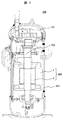
- the compressor 200 of this embodiment is provided with a compression mechanism section 201, a drive shaft 202, and a rotary motor section 203 inside a casing 204 that is also a compression container.
- a power line (not shown) is provided below the unit 203.
- the rotary electric motor unit 203 is a permanent magnet type rotary electric motor composed of a stator 1 on the outer peripheral side and a rotor 8 on the inner peripheral side, and is a drive integrated with the rotor 8 when the rotor 8 is rotated.
- the shaft 202 rotates and the refrigerant is compressed by the compression mechanism 201 at the tip of the drive shaft 202.
- the rotary electric motor unit 203 since the rotary electric motor unit 203 is located inside the casing 204 through which the refrigerant circulates, the components of the rotary electric motor unit 203 are also acted on by the force of the refrigerant flow.
- the interphase insulating sheet 10 to be inserted into the stator 1 is configured as shown in FIGS. 2 to 4, so that even if the flow of the refrigerant acts on the interphase insulating sheet 10, it can withstand this. did.
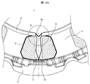
- FIG. 2A is an enlarged top view of the stator 1 of the rotary electric motor unit 203 as viewed from above.
- the slot portion 2 and the teeth portion 5 are provided on the inner peripheral side of the substantially annular stator core 7.
- a plurality of armature windings 6 are formed by winding a coil around each of the teeth portions 5.
- the armature winding 6 and the tooth portion 5 are insulated by a resin slot insulating sheet 3, and the armature windings 6 are insulated by a resin interphase insulating sheet 10.
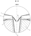
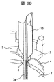
- FIG. 2B is an enlarged view of a portion D in FIG. 2A, and the slot insulating sheet 3 is arranged along the inner surface of the stator core 7 as shown here.
- the slot insulating sheet 3 is a single insulating sheet separated in the vicinity of the center of the slot portion 2, and both ends thereof are bent inward to form a guide portion 3a.
- the interphase insulating sheet 10 is bent outward at both ends, and sandwiched between the respective ends of the insulating sheet 10 by the slot insulating sheet 3 and the armature winding 6, thereby preventing the stator 1 from moving in the radial direction. ing. Further, by disposing the resin insulator 4 above the interphase insulating sheet 10, the interphase insulating sheet 10 is prevented from dropping above the slot portion 2.
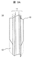
- FIG. 3A is a perspective view of the interphase insulating sheet 10 before being inserted into the stator 1.
- the interphase insulating sheet 10 has notches 12 at both ends in the short direction in order to improve the assemblability when the stator 1 is inserted.
- This notch 12 is arranged only on one side in the longitudinal direction (lower side in FIG. 3A), and the other (upper side in FIG. 3A) is a corner 13 without providing the notch 12. Note that the notch 12 is notched to the vicinity of the fold located at the outermost part at both ends in the short direction.
- FIG. 3B is a perspective view showing a state in the middle of inserting the interphase insulating sheet 10 into the stator 1.
- the armature winding 6 is omitted.
- the notch 12 side of the interphase insulating sheet 10 is set as an insertion side when inserting into the stator 1, and the inner peripheral side is set in the width direction. It can be easily inserted into the stator 1 by being inserted into the slot portion 2 along the crushing guide portion 3a.
- the insulator 4 can be easily inserted into the stator 1 without deteriorating the formability by providing the insulator 4 with the guide for inserting the interphase insulating sheet.
- the interphase insulating sheet 10 has a tapered shape. Therefore, the interphase insulating sheet 10 is easy to insert into the slot portion 2, and is pushed in with the tip having the notch 12 inserted. Thus, it is possible to easily guide to the back of the slot portion 2.
- the shape of the notch 12 is not a stepped shape but an inclined shape, it can be easily guided to the back of the slot portion 2 simply by applying a force so as to be inserted into the back as it is after the tip portion is inserted.
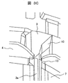
- FIG. 3C is a perspective view showing a state after the interphase insulating sheet 10 is inserted into the stator 1. Also here, the armature winding 6 is omitted.
- FIG. 3C or FIG. 2B after the interphase insulating sheet 10 is inserted, the corners 13 at the upper ends of the interphase insulating sheet 10 are held by the insulator 4 and the slot insulating sheet 3. Even when the refrigerant flow from above acts, the interphase insulating sheet 10 can be prevented from falling off, so that the reliability as an electric motor can be improved.
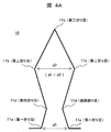
- the interphase insulating sheet 10 of the present embodiment has four or more folds 11 in order to improve reliability and retainability.
- the refrigerant circulates in the periphery of the electric motor or in the slot portion 2 inside, and there is a possibility that the interphase insulating sheet 10 falls off.
- the interphase insulating sheet 10 is thermally deformed along the shape of the slot portion 2 and spreads in the slot portion 2 so that the portion caught by the insulator 4 becomes the slot portion 2. Pulled inward, the interphase insulating sheet 10 becomes easy to drop off.
- the interphase insulating sheet 10 of the present embodiment four or more folds are provided, and the shape is expanded in advance in the slot portion 2 so that the interphase insulating sheet 10 is not easily dropped even if the interphase insulating sheet 10 is thermally deformed.
- the seven-fold interphase insulating sheet 10 shown in the cross-sectional view of FIG. 4A constitutes a corner 13 that is hooked on the insulator 4 by the two first folds 11a of the valley fold, and the circumferential direction between the two first folds 11a.
- the circumferential distance d2 between the two second folds 11b of the mountain fold more than the distance d1
- an extended portion that is hooked on the inner surface of the slot portion 2 is formed.
- the interphase insulating sheet 10 is held on both the insulator 4 side and the slot portion 2 side, and can be prevented from falling off due to the circulation and thermal deformation of the refrigerant.
- the third fold 11c of the mountain fold is provided between the two first folds, and the tip is sharpened, so that the insertion operation is further facilitated, and the valley between each first fold and the second fold is provided.
- the fourth fold line 11d By providing the fourth fold line 11d, the hook on the insulator 4 is further strengthened.
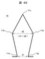
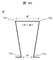
- the extended portion formed between the two second folds 11b can also be formed by a five-fold interphase insulating sheet 10 (FIG. 4B) or a four-fold interphase insulating sheet 10 (FIG. 4C).
- a five-fold interphase insulating sheet 10 FIG. 4B
- a four-fold interphase insulating sheet 10 FIG. 4C
- the extended portion cannot be formed, and the retention on the slot portion 2 side is inferior.
- the assembly including the insertion of the interphase insulating sheet 10 of the permanent magnet type rotary motor into the stator 1 can be improved, and the permanent magnet type rotary motor can be improved.
Abstract
In order to improve ease of assembly and reliability in a permanent magnet rotary electric machine and a compressor using this permanent magnet rotary electric machine, this permanent magnet rotary electric machine is configured from a rotor 8 and a stator 1, and the stator 1 comprises a substantially annular stator core 7, a plurality of slots 2 provided on the inner-circumferential side of the stator core, a plurality of teeth parts 5 provided on the inner-circumferential side of the stator core, a plurality of armature windings 6 formed by winding coils around each of the teeth parts, and a resin interphase insulation sheet 10 arranged between the armature windings and insulating the armature windings from each other. The interphase insulation sheet has a notch 12 on the tip end in the insertion direction.
Description
本発明は、永久磁石式回転電動機およびこれを用いた圧縮機に関する。
The present invention relates to a permanent magnet type rotary electric motor and a compressor using the same.
永久磁石式回転電機およびこれを用いた圧縮機の従来技術としては、例えば特許文献1に記載のものがある。
As a prior art of a permanent magnet type rotating electric machine and a compressor using the same, there is one disclosed in Patent Document 1, for example.
特許文献1に記載の電動機は、同文献の要約書で「端部絶縁部材20の少なくとも一方には、第1の部材30の周方向両端部に段差部31と切欠部32(案内部)が形成されている。第1の巻線絶縁部材70は、切欠部32により案内されてスロット15内に挿入され、段差部31によってスロット15内に固定される。」と説明されるように、固定子鉄心(同文献中では「ステータコア10」)の軸方向両端に配したインシュレータ(同文献中では「端部絶縁部材20」)に段差を設け、これを案内部(同文献中では「切欠部32」)とすることで、相間絶縁シート(同文献中では「第1の巻線絶縁部材70」)をガイドしながら容易に挿入でき、電動機製作時の組立性向上に効果が得られるとしている(同文献の図2、図3、図5、図6など参照)。
The electric motor described in Patent Document 1 is described in the abstract of the same document as “at least one end insulating member 20 has a step portion 31 and a notch portion 32 (guide portion) at both ends in the circumferential direction of the first member 30. The first winding insulating member 70 is guided by the notch 32 and inserted into the slot 15, and is fixed in the slot 15 by the step portion 31. " A step is provided in an insulator (“end insulating member 20” in the same document) disposed at both axial ends of the core (“stator core 10” in the same document), and this is provided as a guide portion (“notch” in the same document). 32 ”), the interphase insulating sheet (“ first winding insulating member 70 ”in the same document) can be easily inserted while guiding, and the effect of improving the assemblability at the time of manufacturing the motor can be obtained. (Fig. 2, Fig. 3, Fig. 5, Fig. Reference, etc.).
しかし、特許文献1の構成では、同文献の図2、図3などに示されるように、インシュレータにガイド部が必要となり、この部分が薄肉部となるため、主に樹脂成型されるインシュレータの成型性が悪化するという問題がある。また、インシュレータに設けたガイド部からの挿入性を向上させた分、そのガイド部からの相間絶縁シートの脱落も発生しやすくなり、ガイド部が相間絶縁シートの保持性の悪化を招くといった問題もある。
However, in the configuration of Patent Document 1, as shown in FIG. 2 and FIG. 3 of the same document, a guide portion is required for the insulator, and this portion becomes a thin portion. There is a problem that the sex gets worse. In addition, since the insertability from the guide portion provided in the insulator is improved, the interphase insulating sheet is likely to drop off from the guide portion, and there is a problem that the guide portion causes deterioration of the retainability of the interphase insulating sheet. is there.
そこで、本発明では、インシュレータに案内部を配さずとも、相間絶縁シートの挿入性を向上させ、永久磁石式回転電動機の組立性向上を達成することを目的とする。
Therefore, an object of the present invention is to improve the insertability of the interphase insulating sheet and achieve the improved assemblability of the permanent magnet type rotary electric motor without arranging the guide portion in the insulator.
また、本発明の別の目的としては、組立てた後の相間絶縁シートの保持性を向上させ、相間絶縁シートが抜け落ち難くすることで、永久磁石式回転電動機の信頼性を向上させることを目的とする。
Another object of the present invention is to improve the reliability of the permanent magnet type rotary electric motor by improving the retainability of the interphase insulating sheet after assembly and making it difficult for the interphase insulating sheet to come off. To do.
上記目的を達成するため本発明の永久磁石式回転電動機は、回転子と固定子から構成され、前記固定子は、略環状の固定子鉄心と、該固定子鉄心の内周側に設けられた複数のスロット部と、前記固定子鉄心の内周側に設けられた複数のティース部と、各々のティース部にコイルを巻き回した複数の電機子巻線と、各々の電機子巻線間に配置され、両者を絶縁する樹脂製の相間絶縁シートと、からなり、該相間絶縁シートは、挿入方向の先端側に切り欠きを有しているものとした。
In order to achieve the above object, a permanent magnet type rotary electric motor of the present invention comprises a rotor and a stator, and the stator is provided on a substantially annular stator core and an inner peripheral side of the stator core. A plurality of slot portions, a plurality of tooth portions provided on the inner peripheral side of the stator core, a plurality of armature windings in which a coil is wound around each tooth portion, and between the armature windings The interphase insulating sheet is disposed and insulates both, and the interphase insulating sheet has a notch on the distal end side in the insertion direction.
また、回転子と固定子から構成され、前記固定子は、略環状の固定子鉄心と、該固定子鉄心の内周側に設けられた複数のティース部と、前記固定子鉄心の内周側に設けられた複数のスロット部と、各々のティース部にコイルを巻き回した複数の電機子巻線と、各々の電機子巻線間に配置され、両者を絶縁する樹脂製の相間絶縁シートと、からなり、前記相間絶縁シートは、四箇所以上の折り目を有する断面形状を有しているものとした。
The stator includes a rotor and a stator, and the stator includes a substantially annular stator core, a plurality of teeth provided on an inner peripheral side of the stator core, and an inner peripheral side of the stator core. A plurality of slot portions provided in each of the plurality of armature windings in which a coil is wound around each of the tooth portions, and a resin-made interphase insulating sheet disposed between the armature windings to insulate them. The interphase insulating sheet has a cross-sectional shape having four or more folds.
本発明によれば、相間絶縁シートの挿入性を向上させ、永久磁石式回転電動機の組立性向上を達成することができる。
According to the present invention, it is possible to improve the insertability of the interphase insulating sheet and improve the assemblability of the permanent magnet type rotary electric motor.
また、相間絶縁シートが抜け落ち難くすることができ、信頼性を向上させることができる。
Also, the interphase insulating sheet can be made difficult to come off, and the reliability can be improved.
以下、本発明の圧縮機、および、それに用いる回転電動機の具体的実施例を、図面に基づいて説明する。
Hereinafter, specific examples of the compressor of the present invention and the rotary electric motor used therefor will be described with reference to the drawings.
先ず、図1の断面図を用いて、本実施例の永久磁石式回転電動機を適用した圧縮機200の概要を説明する。ここに示すように、本実施例の圧縮機200は、圧縮容器でもあるケーシング204の内部に、圧縮機構部201と、駆動軸202と、回転電動機部203とを設けており、また、回転電動機部203の下方に図示しない電源線を設けている。回転電動機部203は、外周側の固定子1と内周側の回転子8から構成された永久磁石式回転電動機であり、回転子8を回転させたときに、回転子8と一体化した駆動軸202が回転し、駆動軸202先端の圧縮機構部201で冷媒を圧縮する。
First, an outline of a compressor 200 to which the permanent magnet type rotary electric motor of this embodiment is applied will be described with reference to the cross-sectional view of FIG. As shown here, the compressor 200 of this embodiment is provided with a compression mechanism section 201, a drive shaft 202, and a rotary motor section 203 inside a casing 204 that is also a compression container. A power line (not shown) is provided below the unit 203. The rotary electric motor unit 203 is a permanent magnet type rotary electric motor composed of a stator 1 on the outer peripheral side and a rotor 8 on the inner peripheral side, and is a drive integrated with the rotor 8 when the rotor 8 is rotated. The shaft 202 rotates and the refrigerant is compressed by the compression mechanism 201 at the tip of the drive shaft 202.
ここで、回転電動機部203は、冷媒が循環するケーシング204の内部に位置しているため、回転電動機部203を構成する諸部品も、冷媒の流れによる力が作用することになる。本実施例では、固定子1に挿入する相間絶縁シート10を、図2~図4のように構成することで、冷媒の流れが相間絶縁シート10に作用したとしても、これに耐え得る構成とした。
Here, since the rotary electric motor unit 203 is located inside the casing 204 through which the refrigerant circulates, the components of the rotary electric motor unit 203 are also acted on by the force of the refrigerant flow. In this embodiment, the interphase insulating sheet 10 to be inserted into the stator 1 is configured as shown in FIGS. 2 to 4, so that even if the flow of the refrigerant acts on the interphase insulating sheet 10, it can withstand this. did.
次に、図2Aと図2Bを用いて、固定子1内の相間絶縁シート10を詳細に説明する。
Next, the interphase insulating sheet 10 in the stator 1 will be described in detail with reference to FIGS. 2A and 2B.
図2Aは、回転電動機部203の固定子1を上方から見た拡大上面図であり、ここに示すように、略環状の固定子鉄心7の内周側には、スロット部2とティース部5が交互に配置されている。また、各々のティース部5にコイルを巻き回すことで複数の電機子巻線6が形成されている。電機子巻線6とティース部5は樹脂製のスロット絶縁シート3で絶縁されており、また、電機子巻線6同士は樹脂製の相間絶縁シート10で絶縁されている。
FIG. 2A is an enlarged top view of the stator 1 of the rotary electric motor unit 203 as viewed from above. As shown here, the slot portion 2 and the teeth portion 5 are provided on the inner peripheral side of the substantially annular stator core 7. Are arranged alternately. A plurality of armature windings 6 are formed by winding a coil around each of the teeth portions 5. The armature winding 6 and the tooth portion 5 are insulated by a resin slot insulating sheet 3, and the armature windings 6 are insulated by a resin interphase insulating sheet 10.
次に、図2Bを用いて、スロット部2内でのスロット絶縁シート3と相間絶縁シート10の配置を更に詳細に説明する。図2Bは、図2AのD部の拡大図であり、ここに示すように、固定子鉄心7の内面に沿ってスロット絶縁シート3が配置されている。スロット絶縁シート3は、スロット部2の中心付近で分離した1枚の絶縁シートであり、その両端の各々を内側に屈曲させて案内部3aを形成している。
Next, the arrangement of the slot insulating sheet 3 and the interphase insulating sheet 10 in the slot portion 2 will be described in more detail with reference to FIG. 2B. FIG. 2B is an enlarged view of a portion D in FIG. 2A, and the slot insulating sheet 3 is arranged along the inner surface of the stator core 7 as shown here. The slot insulating sheet 3 is a single insulating sheet separated in the vicinity of the center of the slot portion 2, and both ends thereof are bent inward to form a guide portion 3a.
一方、相間絶縁シート10は、その両端の各々を外側に屈曲させるとともに、各々の先端をスロット絶縁シート3と電機子巻線6で挟むことで、固定子1の半径方向への移動を防止している。また、相間絶縁シート10の上方に、樹脂製のインシュレータ4を配置することで、相間絶縁シート10がスロット部2の上方に脱落するのを防止している。
On the other hand, the interphase insulating sheet 10 is bent outward at both ends, and sandwiched between the respective ends of the insulating sheet 10 by the slot insulating sheet 3 and the armature winding 6, thereby preventing the stator 1 from moving in the radial direction. ing. Further, by disposing the resin insulator 4 above the interphase insulating sheet 10, the interphase insulating sheet 10 is prevented from dropping above the slot portion 2.
次に、図3Aから図3Cを用いて、本実施例の相間絶縁シート10の形状と、固定子1への装着方法を説明する。
Next, the shape of the interphase insulating sheet 10 according to the present embodiment and a method for mounting the stator 1 will be described with reference to FIGS. 3A to 3C.
図3Aは、固定子1に挿入する前の相間絶縁シート10の斜視図である。ここに示すように、相間絶縁シート10は、固定子1にを挿入する際の組立性を向上するために、短手方向の両端部に切り欠き12を有している。この切り欠き12は、長手方向の一方(図3Aでは下側)のみに配し、他方(図3Aでは上側)は切り欠き12を設けずに角部13としている。なお、切り欠き12は、短手方向両端の最外部に位置する折り目近傍まで切り欠いたものである。
FIG. 3A is a perspective view of the interphase insulating sheet 10 before being inserted into the stator 1. As shown here, the interphase insulating sheet 10 has notches 12 at both ends in the short direction in order to improve the assemblability when the stator 1 is inserted. This notch 12 is arranged only on one side in the longitudinal direction (lower side in FIG. 3A), and the other (upper side in FIG. 3A) is a corner 13 without providing the notch 12. Note that the notch 12 is notched to the vicinity of the fold located at the outermost part at both ends in the short direction.
また、図3Bは、相間絶縁シート10を固定子1に挿入している途中の状態を示す斜視図である。なお、ここでは、電機子巻線6を省略している。ここに示すように、相間絶縁シート10を固定子1に装着するときには、相間絶縁シート10の切り欠き12側を固定子1へ挿入する際の挿入側とするとともに、内周側を幅方向に潰し案内部3aに沿わせながらスロット部2に挿入することで、容易に固定子1へ挿入することができる。このように、本実施例によれば、インシュレータ4に相間絶縁シート挿入用のガイドを配して成形性を悪化させることなく、固定子1への挿入を容易とすることができる。
FIG. 3B is a perspective view showing a state in the middle of inserting the interphase insulating sheet 10 into the stator 1. Here, the armature winding 6 is omitted. As shown here, when the interphase insulating sheet 10 is attached to the stator 1, the notch 12 side of the interphase insulating sheet 10 is set as an insertion side when inserting into the stator 1, and the inner peripheral side is set in the width direction. It can be easily inserted into the stator 1 by being inserted into the slot portion 2 along the crushing guide portion 3a. As described above, according to the present embodiment, the insulator 4 can be easily inserted into the stator 1 without deteriorating the formability by providing the insulator 4 with the guide for inserting the interphase insulating sheet.
つまり、相間絶縁シート10に切り欠き12を設けたことにより、相間絶縁シート10は先細り形状となっているため、スロット部2に挿入し易く、切り欠き12を有する先端部が入った状態で押し込むことで、スロット部2の奥まで簡単に案内することができる。特に、切り欠き12の形状を、段差形状ではなく傾斜形状としたため、先端部を挿入した後、そのまま奥に差し込むように力を加えるだけで容易にスロット部2の奥まで案内することができる。
That is, by providing the notch 12 in the interphase insulating sheet 10, the interphase insulating sheet 10 has a tapered shape. Therefore, the interphase insulating sheet 10 is easy to insert into the slot portion 2, and is pushed in with the tip having the notch 12 inserted. Thus, it is possible to easily guide to the back of the slot portion 2. In particular, since the shape of the notch 12 is not a stepped shape but an inclined shape, it can be easily guided to the back of the slot portion 2 simply by applying a force so as to be inserted into the back as it is after the tip portion is inserted.
図3Cは、相間絶縁シート10を固定子1に挿入した後の状態を示す斜視図である。なお、ここでも、電機子巻線6を省略している。図3Cまたは図2Bに示すように、相間絶縁シート10の挿入後は、相間絶縁シート10の上側両端の角部13が、インシュレータ4とスロット絶縁シート3によって保持されるため、相間絶縁シート10に上方からの冷媒流が作用した場合であっても、相間絶縁シート10の脱落を抑制できるので、電動機としての信頼性を向上させることができる。
FIG. 3C is a perspective view showing a state after the interphase insulating sheet 10 is inserted into the stator 1. Also here, the armature winding 6 is omitted. As shown in FIG. 3C or FIG. 2B, after the interphase insulating sheet 10 is inserted, the corners 13 at the upper ends of the interphase insulating sheet 10 are held by the insulator 4 and the slot insulating sheet 3. Even when the refrigerant flow from above acts, the interphase insulating sheet 10 can be prevented from falling off, so that the reliability as an electric motor can be improved.
次に、図4A~図4Cを用い、相間絶縁シート10の形状について詳細に説明する。本実施例の相間絶縁シート10は、信頼性と保持性を向上させるために四箇所以上の折り目11を有している。
Next, the shape of the interphase insulating sheet 10 will be described in detail with reference to FIGS. 4A to 4C. The interphase insulating sheet 10 of the present embodiment has four or more folds 11 in order to improve reliability and retainability.
上述したように、電動機が圧縮機等に使用される場合、内部において電動機の周辺やスロット部2には冷媒が流通しており、相間絶縁シート10が抜け落ちる虞がある。また、圧縮機運転時に内部が高温となった場合に、相間絶縁シート10がスロット部2の形状に沿って熱変形し、スロット部2の中で広がることでインシュレータ4に引っかかる部分がスロット部2内側へ引き込まれ、相間絶縁シート10は脱落し易くなる。
As described above, when the electric motor is used for a compressor or the like, the refrigerant circulates in the periphery of the electric motor or in the slot portion 2 inside, and there is a possibility that the interphase insulating sheet 10 falls off. In addition, when the inside of the compressor becomes hot during operation of the compressor, the interphase insulating sheet 10 is thermally deformed along the shape of the slot portion 2 and spreads in the slot portion 2 so that the portion caught by the insulator 4 becomes the slot portion 2. Pulled inward, the interphase insulating sheet 10 becomes easy to drop off.
そこで、本実施例の相間絶縁シート10では、四箇所以上の折り目を設け、予めスロット部2内で広げた形状とし、相間絶縁シート10が熱変形しても脱落しにくくしている。
Therefore, in the interphase insulating sheet 10 of the present embodiment, four or more folds are provided, and the shape is expanded in advance in the slot portion 2 so that the interphase insulating sheet 10 is not easily dropped even if the interphase insulating sheet 10 is thermally deformed.
例えば、図4Aの断面図に示す七つ折りの相間絶縁シート10は、谷折の2つの第一折り目11aによりインシュレータ4に引っ掛ける角部13を構成するとともに、2つの第一折り目11a間の周方向距離d1よりも山折の2つの第二折り目11b間の周方向距離d2を大きくすることでスロット部2の内面に引っ掛ける拡張部を形成する。これらにより、相間絶縁シート10は、インシュレータ4側とスロット部2側の両方で保持されることになり、冷媒の流通や熱変形に起因する脱落を防止することができる。また、2つの第一折り目の間に山折の第三折り目11cを設け先が尖る形状とすることで、挿入作業が更に容易になり、また、各第一折り目と第二折り目との間に谷折の第四折り目11dを設けることで、インシュレータ4への引っ掛けが更に強固となる。
For example, the seven-fold interphase insulating sheet 10 shown in the cross-sectional view of FIG. 4A constitutes a corner 13 that is hooked on the insulator 4 by the two first folds 11a of the valley fold, and the circumferential direction between the two first folds 11a. By extending the circumferential distance d2 between the two second folds 11b of the mountain fold more than the distance d1, an extended portion that is hooked on the inner surface of the slot portion 2 is formed. As a result, the interphase insulating sheet 10 is held on both the insulator 4 side and the slot portion 2 side, and can be prevented from falling off due to the circulation and thermal deformation of the refrigerant. In addition, the third fold 11c of the mountain fold is provided between the two first folds, and the tip is sharpened, so that the insertion operation is further facilitated, and the valley between each first fold and the second fold is provided. By providing the fourth fold line 11d, the hook on the insulator 4 is further strengthened.
なお、2つの第二折り目11b間に形成される拡張部は、五つ折りの相間絶縁シート10(図4B)や、四つ折りの相間絶縁シート10(図4C)でも形成できるが、第二折り目を1つしか有さない三つ折りの相間絶縁シート(特許文献1の図5参照)では拡張部を形成することができず、スロット部2側での保持性が劣後する。
The extended portion formed between the two second folds 11b can also be formed by a five-fold interphase insulating sheet 10 (FIG. 4B) or a four-fold interphase insulating sheet 10 (FIG. 4C). In the three-fold interphase insulating sheet having only one (see FIG. 5 of Patent Document 1), the extended portion cannot be formed, and the retention on the slot portion 2 side is inferior.
以上で説明した本実施例の構成によれば、永久磁石式回転電動機の相間絶縁シート10の固定子1への挿入を含めた組立性を向上させることができるのに加え、永久磁石式回転電動機や圧縮機の使用中の相間絶縁シート10の脱落についての信頼性向上を図ることが可能である。
According to the configuration of the present embodiment described above, the assembly including the insertion of the interphase insulating sheet 10 of the permanent magnet type rotary motor into the stator 1 can be improved, and the permanent magnet type rotary motor can be improved. In addition, it is possible to improve the reliability of the interphase insulating sheet 10 during the use of the compressor.
1 固定子
2 スロット部
3 スロット絶縁シート
3a 案内部
4 インシュレータ
5 ティース部
6 電機子巻線
7 固定子鉄心
8 回転子
10 相間絶縁シート
11 折り目
11a 第一折り目
11b 第二折り目
11c 第三折り目
11d 第四折り目
12 切り欠き
13 角部
200 圧縮機
201 圧縮機構部
202 駆動軸
203 回転電動機部
204 ケーシング DESCRIPTION OFSYMBOLS 1 Stator 2 Slot part 3 Slot insulation sheet 3a Guide part 4 Insulator 5 Teeth part 6 Armature winding 7 Stator core 8 Rotor 10 Interphase insulation sheet 11 Fold 11a First fold 11b Second fold 11c Third fold 11d First Fourth fold 12 Notch 13 Corner portion 200 Compressor 201 Compression mechanism portion 202 Drive shaft 203 Rotating motor portion 204 Casing
2 スロット部
3 スロット絶縁シート
3a 案内部
4 インシュレータ
5 ティース部
6 電機子巻線
7 固定子鉄心
8 回転子
10 相間絶縁シート
11 折り目
11a 第一折り目
11b 第二折り目
11c 第三折り目
11d 第四折り目
12 切り欠き
13 角部
200 圧縮機
201 圧縮機構部
202 駆動軸
203 回転電動機部
204 ケーシング DESCRIPTION OF
Claims (6)
- 回転子と固定子から構成される永久磁石式回転電動機であって、
前記固定子は、
略環状の固定子鉄心と、
該固定子鉄心の内周側に設けられた複数のスロット部と、
前記固定子鉄心の内周側に設けられた複数のティース部と、
各々のティース部にコイルを巻き回した複数の電機子巻線と、
各々の電機子巻線間に配置され、両者を絶縁する樹脂製の相間絶縁シートと、からなり、
該相間絶縁シートは、挿入方向の先端側に切り欠きを有していることを特徴とする永久磁石式回転電動機。 A permanent magnet rotary electric motor composed of a rotor and a stator,
The stator is
A substantially annular stator core;
A plurality of slot portions provided on the inner peripheral side of the stator core;
A plurality of teeth provided on the inner peripheral side of the stator core;
A plurality of armature windings each having a coil wound around each tooth portion;
It is arranged between each armature winding and consists of a resin phase insulation sheet that insulates both,
The interphase insulating sheet has a notch on the leading end side in the insertion direction. - 請求項1に記載の永久磁石式回転電動機において、
さらに、前記回転子鉄心の上方に樹脂製のインシュレータを有しており、
前記相間絶縁シートの挿入方向の後端側は、前記インシュレータによって保持されることを特徴とする永久磁石式回転電動機。 In the permanent magnet type rotary electric motor according to claim 1,
Furthermore, it has a resin insulator above the rotor core,
The permanent magnet rotary electric motor, wherein a rear end side of the interphase insulating sheet in the insertion direction is held by the insulator. - 請求項1に記載の永久磁石式回転電動機において、
前記間絶縁シートの切り欠きは、電源線引出側に設けられていることを特徴とする永久磁石式回転電動機。 In the permanent magnet type rotary electric motor according to claim 1,
The notch of the intermediate insulating sheet is provided on the power line drawing side, and is a permanent magnet type rotary electric motor. - 回転子と固定子から構成される永久磁石式回転電動機であって、
前記固定子は、
略環状の固定子鉄心と、
該固定子鉄心の内周側に設けられた複数のティース部と、
前記固定子鉄心の内周側に設けられた複数のスロット部と、
各々のティース部にコイルを巻き回した複数の電機子巻線と、
各々の電機子巻線間に配置され、両者を絶縁する樹脂製の相間絶縁シートと、からなり、
前記相間絶縁シートは、四箇所以上の折り目を有する断面形状を有していることを特徴とする永久磁石式回転電動機。 A permanent magnet rotary electric motor composed of a rotor and a stator,
The stator is
A substantially annular stator core;
A plurality of teeth provided on the inner peripheral side of the stator core;
A plurality of slot portions provided on the inner peripheral side of the stator core;
A plurality of armature windings each having a coil wound around each tooth portion;
It is arranged between each armature winding and consists of a resin phase insulation sheet that insulates both,
The interphase insulating sheet has a cross-sectional shape having four or more folds, and is a permanent magnet type rotary electric motor. - 請求項4に記載の永久磁石式回転電動機において、
前記相間絶縁シートの端部の二つの折り目間の周方向距離よりも、
他の二つの折り目間の周方向距離が大きいことを特徴とする永久磁石式回転電動機。 In the permanent magnet type rotary electric motor according to claim 4,
Than the circumferential distance between two creases at the end of the interphase insulating sheet,
A permanent magnet type rotary electric motor having a large circumferential distance between the other two folds. - 請求項1から請求項5の何れか一項に記載の永久磁石式回転電動機と、
該永久磁石式回転電動機の回転子とともに回転する駆動軸と、
該駆動軸の先端に設けられ、該駆動軸の回転により冷媒を圧縮する圧縮機構部と、
前記永久磁石式回転電動機、前記駆動軸、および、前記圧縮機構部を内蔵したケーシングと、
からなることを特徴とする圧縮機。 The permanent magnet type rotary electric motor according to any one of claims 1 to 5,
A drive shaft that rotates with the rotor of the permanent magnet type rotary electric motor;
A compression mechanism that is provided at the tip of the drive shaft and compresses the refrigerant by rotation of the drive shaft;
A casing incorporating the permanent magnet type rotary electric motor, the drive shaft, and the compression mechanism;
The compressor characterized by consisting of.
Applications Claiming Priority (2)
| Application Number | Priority Date | Filing Date | Title |
|---|---|---|---|
| JP2016215077A JP6578267B2 (en) | 2016-11-02 | 2016-11-02 | Permanent magnet type rotary electric motor and compressor using the same |
| JP2016-215077 | 2016-11-02 |
Publications (1)
| Publication Number | Publication Date |
|---|---|
| WO2018083916A1 true WO2018083916A1 (en) | 2018-05-11 |
Family
ID=62076031
Family Applications (1)
| Application Number | Title | Priority Date | Filing Date |
|---|---|---|---|
| PCT/JP2017/034882 WO2018083916A1 (en) | 2016-11-02 | 2017-09-27 | Permanent magnet rotary electric machine and compessor using same |
Country Status (3)
| Country | Link |
|---|---|
| JP (1) | JP6578267B2 (en) |
| TW (1) | TWI663814B (en) |
| WO (1) | WO2018083916A1 (en) |
Cited By (3)
| Publication number | Priority date | Publication date | Assignee | Title |
|---|---|---|---|---|
| DE102019112534A1 (en) * | 2019-05-14 | 2020-11-19 | Hanon Systems | Device for driving a compressor with an insulation arrangement |
| CN112564363A (en) * | 2020-11-23 | 2021-03-26 | 珠海格力节能环保制冷技术研究中心有限公司 | Insulation system, motor |
| US11581775B2 (en) | 2019-05-14 | 2023-02-14 | Hanon Systems | Device for driving a compressor with an insulation arrangement |
Citations (4)
| Publication number | Priority date | Publication date | Assignee | Title |
|---|---|---|---|---|
| DE102006048967A1 (en) * | 2006-10-17 | 2008-04-24 | Siemens Ag | Stator for e.g. asynchronous machine, has separator forming overlapping of spool and separator in area of flange by recesses, where flange is provided at base and separator engages in area of base in recesses at cover |
| JP2011130566A (en) * | 2009-12-17 | 2011-06-30 | Aichi Elec Co | Electric motor |
| JP2012092766A (en) * | 2010-10-28 | 2012-05-17 | Mitsubishi Electric Corp | Electric compressor, and control device thereof |
| WO2016093047A1 (en) * | 2014-12-10 | 2016-06-16 | ダイキン工業株式会社 | Stator, motor and compressor |
Family Cites Families (5)
| Publication number | Priority date | Publication date | Assignee | Title |
|---|---|---|---|---|
| JP2005160261A (en) * | 2003-11-28 | 2005-06-16 | Hitachi Ltd | Armature winding and rotating electric machine using same |
| WO2006137125A1 (en) * | 2005-06-21 | 2006-12-28 | Mitsubishi Denki Kabushiki Kaisha | Armature for rotary electric motor, rotary electric motor, and method of producing the rotary electric motor |
| JP4528825B2 (en) * | 2007-12-21 | 2010-08-25 | 日立アプライアンス株式会社 | Self-starting permanent magnet synchronous motor and compressor using the same |
| JP5999936B2 (en) * | 2012-03-14 | 2016-09-28 | アイチエレック株式会社 | Insulating sheet manufacturing method and insulating sheet manufacturing apparatus |
| JP2016135060A (en) * | 2015-01-22 | 2016-07-25 | トヨタ自動車株式会社 | Rotary electric machine stator |
-
2016
- 2016-11-02 JP JP2016215077A patent/JP6578267B2/en active Active
-
2017
- 2017-09-27 WO PCT/JP2017/034882 patent/WO2018083916A1/en active Application Filing
- 2017-11-01 TW TW106137693A patent/TWI663814B/en active
Patent Citations (4)
| Publication number | Priority date | Publication date | Assignee | Title |
|---|---|---|---|---|
| DE102006048967A1 (en) * | 2006-10-17 | 2008-04-24 | Siemens Ag | Stator for e.g. asynchronous machine, has separator forming overlapping of spool and separator in area of flange by recesses, where flange is provided at base and separator engages in area of base in recesses at cover |
| JP2011130566A (en) * | 2009-12-17 | 2011-06-30 | Aichi Elec Co | Electric motor |
| JP2012092766A (en) * | 2010-10-28 | 2012-05-17 | Mitsubishi Electric Corp | Electric compressor, and control device thereof |
| WO2016093047A1 (en) * | 2014-12-10 | 2016-06-16 | ダイキン工業株式会社 | Stator, motor and compressor |
Cited By (3)
| Publication number | Priority date | Publication date | Assignee | Title |
|---|---|---|---|---|
| DE102019112534A1 (en) * | 2019-05-14 | 2020-11-19 | Hanon Systems | Device for driving a compressor with an insulation arrangement |
| US11581775B2 (en) | 2019-05-14 | 2023-02-14 | Hanon Systems | Device for driving a compressor with an insulation arrangement |
| CN112564363A (en) * | 2020-11-23 | 2021-03-26 | 珠海格力节能环保制冷技术研究中心有限公司 | Insulation system, motor |
Also Published As
| Publication number | Publication date |
|---|---|
| JP2018074848A (en) | 2018-05-10 |
| TWI663814B (en) | 2019-06-21 |
| JP6578267B2 (en) | 2019-09-18 |
| TW201818638A (en) | 2018-05-16 |
Similar Documents
| Publication | Publication Date | Title |
|---|---|---|
| CN103023167B (en) | Motor and method of manufacturing motor | |
| JP5045909B2 (en) | Lamination | |
| WO2018083916A1 (en) | Permanent magnet rotary electric machine and compessor using same | |
| US9059611B2 (en) | Stator core | |
| JP6107386B2 (en) | Motor and compressor | |
| JP2010115108A (en) | Electric motor | |
| US10230282B2 (en) | Motor and stator thereof | |
| JP4788881B2 (en) | Manufacturing method of electric motor | |
| US10038348B2 (en) | Liner, stator assembly and associated method | |
| JP6001167B2 (en) | Magnet scattering prevention and holding structure for rotating electrical machines | |
| JP5515656B2 (en) | Insulation structure of concentrated winding motor | |
| JP6914346B2 (en) | Manufacturing method of stator, motor, compressor, air conditioner and stator | |
| KR102168628B1 (en) | Electromotive compressor motor | |
| JP6206206B2 (en) | Interphase insulating sheet in rotating electrical machine, rotating electrical machine and in-vehicle electric compressor | |
| JP5953933B2 (en) | Stator and compressor | |
| JP2018074848A5 (en) | ||
| JP6008662B2 (en) | Stator manufacturing method | |
| US5053657A (en) | Miniature motor | |
| JP7086212B2 (en) | Manufacturing method of stator, motor, compressor, air conditioner and stator | |
| JP6776958B2 (en) | How to manufacture the stator | |
| WO2022239097A1 (en) | Stator, motor, blower, method for manufacturing stator, and method for manufacturing motor | |
| JP5709781B2 (en) | Motor armature | |
| JP2005130540A (en) | Motor | |
| JP2011004481A (en) | Stator | |
| JP4926192B2 (en) | Electric motor stator |
Legal Events
| Date | Code | Title | Description |
|---|---|---|---|
| 121 | Ep: the epo has been informed by wipo that ep was designated in this application |
Ref document number: 17866494 Country of ref document: EP Kind code of ref document: A1 |
|
| NENP | Non-entry into the national phase |
Ref country code: DE |
|
| 122 | Ep: pct application non-entry in european phase |
Ref document number: 17866494 Country of ref document: EP Kind code of ref document: A1 |