WO2018079202A1 - 反射防止フィルム、偏光板、画像表示装置、及び反射防止物品 - Google Patents
反射防止フィルム、偏光板、画像表示装置、及び反射防止物品 Download PDFInfo
- Publication number
- WO2018079202A1 WO2018079202A1 PCT/JP2017/035834 JP2017035834W WO2018079202A1 WO 2018079202 A1 WO2018079202 A1 WO 2018079202A1 JP 2017035834 W JP2017035834 W JP 2017035834W WO 2018079202 A1 WO2018079202 A1 WO 2018079202A1
- Authority
- WO
- WIPO (PCT)
- Prior art keywords
- antireflection film
- refractive index
- inorganic particles
- index layer
- low refractive
- Prior art date
- Legal status (The legal status is an assumption and is not a legal conclusion. Google has not performed a legal analysis and makes no representation as to the accuracy of the status listed.)
- Ceased
Links
Classifications
-
- G—PHYSICS
- G02—OPTICS
- G02B—OPTICAL ELEMENTS, SYSTEMS OR APPARATUS
- G02B1/00—Optical elements characterised by the material of which they are made; Optical coatings for optical elements
- G02B1/10—Optical coatings produced by application to, or surface treatment of, optical elements
- G02B1/11—Anti-reflection coatings
-
- G—PHYSICS
- G02—OPTICS
- G02B—OPTICAL ELEMENTS, SYSTEMS OR APPARATUS
- G02B1/00—Optical elements characterised by the material of which they are made; Optical coatings for optical elements
- G02B1/10—Optical coatings produced by application to, or surface treatment of, optical elements
- G02B1/11—Anti-reflection coatings
- G02B1/111—Anti-reflection coatings using layers comprising organic materials
-
- B—PERFORMING OPERATIONS; TRANSPORTING
- B32—LAYERED PRODUCTS
- B32B—LAYERED PRODUCTS, i.e. PRODUCTS BUILT-UP OF STRATA OF FLAT OR NON-FLAT, e.g. CELLULAR OR HONEYCOMB, FORM
- B32B27/00—Layered products comprising a layer of synthetic resin
- B32B27/18—Layered products comprising a layer of synthetic resin characterised by the use of special additives
- B32B27/20—Layered products comprising a layer of synthetic resin characterised by the use of special additives using fillers, pigments, thixotroping agents
-
- B—PERFORMING OPERATIONS; TRANSPORTING
- B32—LAYERED PRODUCTS
- B32B—LAYERED PRODUCTS, i.e. PRODUCTS BUILT-UP OF STRATA OF FLAT OR NON-FLAT, e.g. CELLULAR OR HONEYCOMB, FORM
- B32B7/00—Layered products characterised by the relation between layers; Layered products characterised by the relative orientation of features between layers, or by the relative values of a measurable parameter between layers, i.e. products comprising layers having different physical, chemical or physicochemical properties; Layered products characterised by the interconnection of layers
- B32B7/02—Physical, chemical or physicochemical properties
-
- G—PHYSICS
- G02—OPTICS
- G02B—OPTICAL ELEMENTS, SYSTEMS OR APPARATUS
- G02B1/00—Optical elements characterised by the material of which they are made; Optical coatings for optical elements
- G02B1/10—Optical coatings produced by application to, or surface treatment of, optical elements
- G02B1/14—Protective coatings, e.g. hard coatings
-
- G—PHYSICS
- G02—OPTICS
- G02B—OPTICAL ELEMENTS, SYSTEMS OR APPARATUS
- G02B5/00—Optical elements other than lenses
- G02B5/30—Polarising elements
-
- G—PHYSICS
- G02—OPTICS
- G02F—OPTICAL DEVICES OR ARRANGEMENTS FOR THE CONTROL OF LIGHT BY MODIFICATION OF THE OPTICAL PROPERTIES OF THE MEDIA OF THE ELEMENTS INVOLVED THEREIN; NON-LINEAR OPTICS; FREQUENCY-CHANGING OF LIGHT; OPTICAL LOGIC ELEMENTS; OPTICAL ANALOGUE/DIGITAL CONVERTERS
- G02F1/00—Devices or arrangements for the control of the intensity, colour, phase, polarisation or direction of light arriving from an independent light source, e.g. switching, gating or modulating; Non-linear optics
- G02F1/01—Devices or arrangements for the control of the intensity, colour, phase, polarisation or direction of light arriving from an independent light source, e.g. switching, gating or modulating; Non-linear optics for the control of the intensity, phase, polarisation or colour
- G02F1/13—Devices or arrangements for the control of the intensity, colour, phase, polarisation or direction of light arriving from an independent light source, e.g. switching, gating or modulating; Non-linear optics for the control of the intensity, phase, polarisation or colour based on liquid crystals, e.g. single liquid crystal display cells
- G02F1/133—Constructional arrangements; Operation of liquid crystal cells; Circuit arrangements
- G02F1/1333—Constructional arrangements; Manufacturing methods
- G02F1/1335—Structural association of cells with optical devices, e.g. polarisers or reflectors
-
- G—PHYSICS
- G02—OPTICS
- G02B—OPTICAL ELEMENTS, SYSTEMS OR APPARATUS
- G02B5/00—Optical elements other than lenses
- G02B5/30—Polarising elements
- G02B5/3025—Polarisers, i.e. arrangements capable of producing a definite output polarisation state from an unpolarised input state
-
- G—PHYSICS
- G02—OPTICS
- G02F—OPTICAL DEVICES OR ARRANGEMENTS FOR THE CONTROL OF LIGHT BY MODIFICATION OF THE OPTICAL PROPERTIES OF THE MEDIA OF THE ELEMENTS INVOLVED THEREIN; NON-LINEAR OPTICS; FREQUENCY-CHANGING OF LIGHT; OPTICAL LOGIC ELEMENTS; OPTICAL ANALOGUE/DIGITAL CONVERTERS
- G02F1/00—Devices or arrangements for the control of the intensity, colour, phase, polarisation or direction of light arriving from an independent light source, e.g. switching, gating or modulating; Non-linear optics
- G02F1/01—Devices or arrangements for the control of the intensity, colour, phase, polarisation or direction of light arriving from an independent light source, e.g. switching, gating or modulating; Non-linear optics for the control of the intensity, phase, polarisation or colour
- G02F1/13—Devices or arrangements for the control of the intensity, colour, phase, polarisation or direction of light arriving from an independent light source, e.g. switching, gating or modulating; Non-linear optics for the control of the intensity, phase, polarisation or colour based on liquid crystals, e.g. single liquid crystal display cells
- G02F1/133—Constructional arrangements; Operation of liquid crystal cells; Circuit arrangements
- G02F1/1333—Constructional arrangements; Manufacturing methods
- G02F1/1335—Structural association of cells with optical devices, e.g. polarisers or reflectors
- G02F1/133502—Antiglare, refractive index matching layers
-
- G—PHYSICS
- G02—OPTICS
- G02F—OPTICAL DEVICES OR ARRANGEMENTS FOR THE CONTROL OF LIGHT BY MODIFICATION OF THE OPTICAL PROPERTIES OF THE MEDIA OF THE ELEMENTS INVOLVED THEREIN; NON-LINEAR OPTICS; FREQUENCY-CHANGING OF LIGHT; OPTICAL LOGIC ELEMENTS; OPTICAL ANALOGUE/DIGITAL CONVERTERS
- G02F1/00—Devices or arrangements for the control of the intensity, colour, phase, polarisation or direction of light arriving from an independent light source, e.g. switching, gating or modulating; Non-linear optics
- G02F1/01—Devices or arrangements for the control of the intensity, colour, phase, polarisation or direction of light arriving from an independent light source, e.g. switching, gating or modulating; Non-linear optics for the control of the intensity, phase, polarisation or colour
- G02F1/13—Devices or arrangements for the control of the intensity, colour, phase, polarisation or direction of light arriving from an independent light source, e.g. switching, gating or modulating; Non-linear optics for the control of the intensity, phase, polarisation or colour based on liquid crystals, e.g. single liquid crystal display cells
- G02F1/133—Constructional arrangements; Operation of liquid crystal cells; Circuit arrangements
- G02F1/1333—Constructional arrangements; Manufacturing methods
- G02F1/1335—Structural association of cells with optical devices, e.g. polarisers or reflectors
- G02F1/133528—Polarisers
Definitions
- the present invention relates to an antireflection film, a polarizing plate, an image display device, and an antireflection article.
- an antireflection film may be provided.
- an antireflection function may be provided by an antireflection film.
- Patent Documents 1 and 2 disclose hollow particles such as hollow silica. And an antireflective film in which a low refractive index layer containing a binder resin is laminated on a substrate.
- An object of the present invention is to provide an antireflection film that is excellent in antireflection properties and resistance to repeated bending and has little decrease in antireflection properties after repeated bending, a polarizing plate having the antireflection film, an image display device, and an antireflection article. Is to provide.
- An antireflection film having a base material and a low refractive index layer,
- the low refractive index layer contains inorganic particles and a binder resin,
- the average primary particle diameter of the inorganic particles is R and the particle interval is K
- the average particle interval Ka satisfies the following equation (1)
- the full width at half maximum Kh in the distribution curve of the particle interval K is the following equation (2).
- the antireflective film whose surface roughness of the surface on the opposite side to the said base material of the said low-refractive-index layer is 20 nm or less.
- Ka ⁇ 1.1R (1) Kh ⁇ 0.25R (2) ⁇ 2> The antireflection film as described in ⁇ 1>, wherein the number of breaks and folds measured with an MIT tester in accordance with JIS P 8115: 2001 is 10,000 or more.
- ⁇ 3> The antireflective film as described in ⁇ 1> or ⁇ 2> whose average primary particle diameter R of the said inorganic particle is 200 nm or less.
- ⁇ 4> The antireflection film according to any one of ⁇ 1> to ⁇ 3>, wherein the inorganic particles are inorganic particles having a hollow structure.
- ⁇ 5> The antireflection film according to any one of ⁇ 1> to ⁇ 4>, wherein a hard coat layer is provided between the substrate and the low refractive index layer.
- ⁇ 6> The antireflection film according to any one of ⁇ 1> to ⁇ 5>, wherein the pencil hardness under a load of 500 g measured according to JIS K 5600-5-4: 1999 is 2H or more.
- ⁇ 7> The antireflection film according to any one of ⁇ 1> to ⁇ 6>, wherein an average reflectance in a wavelength region of 450 to 650 nm is 2% or less.
- ⁇ 8> The antireflection film according to any one of ⁇ 1> to ⁇ 7>, wherein the base material contains an aromatic polyamide.
- ⁇ 9> The antireflection film according to any one of ⁇ 1> to ⁇ 8>, wherein the Kh is 0.20R or less.
- a polarizing plate comprising the antireflection film according to any one of ⁇ 1> to ⁇ 9>.
- ⁇ 11> ⁇ 1>- ⁇ 9> The image display apparatus which has an antireflection film as described in any one of ⁇ 1>, or the polarizing plate as described in ⁇ 10>.
- ⁇ 12> An antireflective article comprising the antireflective film according to any one of ⁇ 1> to ⁇ 9>.
- an antireflection film excellent in antireflection properties and resistance to repeated bending and having little decrease in antireflection properties after repeated bending a polarizing plate having the antireflection film, an image display device, and an antireflection article are provided. Can be provided.
- the antireflection film of the present invention is An antireflection film having a base material and a low refractive index layer,
- the low refractive index layer contains inorganic particles and a binder resin,
- the average primary particle diameter of the inorganic particles is R and the particle interval is K
- the average particle interval Ka satisfies the following equation (1)
- the full width at half maximum Kh in the distribution curve of the particle interval K is the following equation (2).
- Meet It is an antireflection film whose surface roughness of the surface on the opposite side to the substrate of the low refractive index layer is 20 nm or less.
- the antireflection film of the present invention has a low refractive index layer directly on the substrate or via another layer.
- the average primary particle diameter of the inorganic particles contained in the low refractive index layer of the antireflection film of the present invention is R and the particle interval is K
- the full width at half maximum Kh in the distribution curve of the average particle interval Ka and the particle interval K is:
- the particle interval K represents the distance between the centers of two particles present at the closest positions.
- the above K, Ka, and Kh were calculated as follows.
- the antireflection film was cut in the thickness direction (perpendicular to the film surface) to obtain a cross section, and the cross section was observed with a transmission electron microscope (JEM-1200EX II, manufactured by JEOL Ltd.).
- the particle interval K was obtained for each particle, and the number average value of the obtained K was calculated as Ka.
- a frequency distribution curve of the obtained particle interval K is drawn, and a particle interval (K 1 and K 2 , where K 2 > K 1) that is 1/2 the particle interval indicating the maximum frequency from the obtained distribution curve. )
- Kh was calculated from the following formula (3).
- Kh (K 2 ⁇ K 1 ) / R (3)
- R is the particle size obtained as an equivalent circle diameter for 500 inorganic particles by cutting the antireflection film in the thickness direction and observing the cross section with a transmission electron microscope in the same manner as the method for obtaining the particle spacing K.
- the inorganic particles in the low refractive index layer of the antireflection film of the present invention have an average particle spacing of a certain ratio or more with respect to the average primary particle diameter (R). (Ka) and the distribution of the particle spacing is also controlled. Thereby, the elasticity of the whole low refractive index layer becomes high, and the micro crack of the film by repeated bending is suppressed. Therefore, the present inventors presume that a decrease in antireflection properties after repeated bending (hereinafter also referred to as “repetitive folding antireflection durability”) is suppressed.
- Ka is 1.1 times or more of R, preferably 1.15 times or more, and more preferably 1.20 times or more from the viewpoint of durability against repeated bending antireflection. Further, from the viewpoint of antireflection properties, it is preferably 1.50 times or less of R, and more preferably 1.40 times or less.
- Kh is 0.25 times or less of R, and preferably 0.20 times or less.
- the low refractive index layer preferably has a refractive index at a wavelength of 550 nm of 1.30 to 1.51, more preferably 1.30 to 1.46, and preferably 1.32 to 1.38. Further preferred. By making the refractive index within the above range, the reflectance can be suppressed and the film strength can be maintained, which is preferable.
- the surface roughness (Ra) of the surface of the low refractive index layer opposite to the substrate is 20 nm or less.
- Ra can be measured by a general surface roughness meter in accordance with Japanese Industrial Standard (JIS) B 0601: 1994.
- JIS Japanese Industrial Standard
- a stylus type surface roughness meter “Surfcoder SE3500” ⁇ manufactured by Kosaka Laboratory Ltd. ⁇ It is also suitable to use.
- Ra is more preferably 10 nm or less, still more preferably 7 nm or less, and particularly preferably 5 nm or less.
- the inorganic particles contained in the low-refractive index layer of the present invention are not particularly limited as long as the refractive index of the low-refractive index layer is within the above-mentioned preferable range, and include inorganic particles such as magnesium fluoride or silica.
- the inorganic particles may be crystalline or amorphous.
- the inorganic particles are preferably monodisperse particles.
- the shape of the inorganic particles is most preferably a spherical diameter, but may be indefinite.
- inorganic particles having a porous or hollow structure are silica having a hollow structure (silicon oxide). Particles.
- the surface of the inorganic particles may be treated with at least one of hydrolyzate of organosilane and partial condensate thereof.
- hydrolyzate of organosilane and partial condensate thereof examples include those described in JP-A 2007-298974, paragraphs [0136] to [0145].
- the inorganic particles include inorganic fine particles described in JP-A-2007-298974, hollow particles described in JP-A-2002-317152, JP-A-2003-202406, and JP-A-2003-292831. Silica fine particles can be suitably used.
- the average primary particle diameter of the inorganic particles is preferably 200 nm or less, more preferably 10 nm to 200 nm, and still more preferably 50 to 120 nm. It is preferable that the average primary particle diameter of the inorganic particles be 200 nm or less because both the antireflection effect and the blackened appearance can be achieved. In particular, when the average primary particle diameter of the inorganic particles is 50 nm or more, the scratch resistance when used as the uppermost layer is improved, which is preferable.
- the refractive index of the inorganic particles is preferably 1.46 or less, more preferably 1.15 to 1.46, still more preferably 1.17 to 1.35, and particularly preferably 1.17 to 1. 30.
- the content of the inorganic particles in the low refractive index layer is preferably adjusted so that the average particle spacing Ka of the inorganic particles satisfies the above formula (1).
- the filling rate of the inorganic particles in the low refractive index layer is preferably 39% by volume or less, more preferably 19 to 39% by volume, and even more preferably 25 to 35% by volume. .
- Binder resin The binder resin contained in the low refractive index layer is not particularly limited as long as the refractive index of the low refractive index layer is within the above-mentioned preferable range.
- JP 2007-298974 A, JP 2002-317152 A Known binder resins described in JP-A Nos. 2003-202406 and 2003-292831 can be used.
- Binder resin may use only 1 type or may use 2 or more types together.
- the binder resin is preferably a monomer or oligomer (polymerizable compound) polymer.
- the monomer (a) used for formation of the hard-coat layer mentioned later is mentioned, for example.
- Monomers may be used alone or in combination of two or more.
- the binder resin a monomer having a high elongation rate, in particular, a binder resin having an elongation rate of 200% or more can be used in combination.
- the elongation rate is obtained by dividing the amount of elongation until the material in the form of a film breaks from the initial stage (distance obtained by subtracting the original distance between the marked lines from the distance between the broken marked lines) by the original distance between the marked lines.
- the ratio is indicated by the following formula (4).
- E is the elongation percentage
- E 2 is the distance between the broken marked lines
- E 1 the original distance between the marked lines.
- E (%) 100 ⁇ (E 2 ⁇ E 1 ) / E 1 (4)
- the elongation percentage was calculated using the distance between fractured marked lines measured according to JIS K 6251: 1993.
- binder resins with an elongation of 200% or more examples include: Byron series (trade name): manufactured by Toyobo Co., Ltd., Samprene series and Sunletan series (both trade names): manufactured by Sanyo Chemical Co., Ltd. Specific examples include Byron UR-1510, Byron UR-2300, Byron UR-3200, Byron UR-3260, Byron UR-8300, Samprene LQ-3300, Samprene LQ-3358, Sunletan TIM-2011A, etc. Can be preferably used. Moreover, the compound which introduce
- the low refractive index layer is preferably formed by coating using a coating composition for forming a low refractive index layer.
- the coating composition for forming a low refractive index layer preferably contains the inorganic particles, a polymerizable compound that forms the binder resin, and a solvent.
- the solid content concentration of the coating composition for forming a low refractive index layer is appropriately selected depending on the application, but is generally about 0.01 to 60% by mass, preferably 0.5 to 50%.
- the mass is preferably about 1% by mass, particularly preferably about 1 to 20% by mass.
- -Polymerization initiator- It does not specifically limit as a polymerization initiator, A well-known polymerization initiator can be used. As a polymerization initiator, the polymerization initiator which can be used in formation of the hard-coat layer mentioned later is mentioned, for example.
- the addition amount of the polymerization initiator is not particularly limited, but is preferably 0.1 to 15% by mass, and preferably 0.5 to 10% by mass with respect to the total solid content in the low refractive index layer forming composition. Is more preferably 1 to 5% by mass.
- the solvent contained in the coating solution composition for the low refractive index layer is not particularly limited as long as the polymerizable compound forming the binder resin is uniformly dissolved or dispersed without causing precipitation. Two or more kinds of solvents can be used in combination.
- ketones acetone, methyl ethyl ketone, methyl isobutyl ketone, etc.
- esters ethyl acetate, butyl acetate, propylene glycol monomethyl ether acetate, etc.
- ethers tetrahydrofuran, 1,4-dioxane, etc.
- alcohols Methanol, ethanol, isopropyl alcohol, butanol, ethylene glycol, etc.
- aromatic hydrocarbons toluene, xylene, etc.
- silicone-based or fluorine-based antifouling agents for the purpose of imparting properties such as antifouling properties, water resistance, chemical resistance, and slipping properties
- known silicone-based or fluorine-based antifouling agents, slipping agents, and the like can be appropriately added.
- these additives it is preferably added in the range of 0 to 20% by mass of the total solid content of the low refractive index layer, more preferably in the range of 0 to 10% by mass. Particularly preferred is 0 to 5% by mass.
- the low refractive index layer is irradiated with ionizing radiation at the same time as coating, or after coating and drying a coating composition in which inorganic particles, a polymerizable compound that forms a binder resin, and other optional components are dissolved or dispersed. And light irradiation, electron beam irradiation, etc.), or it is preferably formed by being cured by a crosslinking reaction or a polymerization reaction by heating.
- the coating method of the coating composition for forming a low refractive index layer is not particularly limited, and a known method can be used. Examples include dip coating, air knife coating, curtain coating, roller coating, die coating, wire bar coating, and gravure coating.
- the coating composition for forming a low refractive index layer on the base material or a layer (for example, a hard coat layer) that may be provided between the base material and the low refractive index layer as described above heat and light are applied. It is preferable to perform a curing treatment by at least one means of irradiation.
- the film thickness of the low refractive index layer is preferably 200 nm or less, more preferably 50 nm to 120 nm, and still more preferably 80 to 120 nm.
- the substrate of the antireflection film of the present invention preferably has a visible light region transmittance of 70% or more, more preferably 80% or more.
- the substrate preferably contains a polymer resin.
- Polymer resin As the polymer resin, a polymer excellent in optical transparency, mechanical strength, thermal stability, and the like is preferable.
- polycarbonate polymers such as polyethylene terephthalate (PET), polyethylene naphthalate (PEN), acrylic polymers such as polymethyl methacrylate (PMMA), polystyrene, acrylonitrile / styrene copolymer (AS resin), etc.
- PET polyethylene terephthalate
- PEN polyethylene naphthalate
- acrylic polymers such as polymethyl methacrylate (PMMA)
- PMMA polymethyl methacrylate
- polystyrene polystyrene
- AS resin acrylonitrile / styrene copolymer
- Polyolefins such as polyethylene and polypropylene, norbornene resins, polyolefin polymers such as ethylene / propylene copolymers, amide polymers such as vinyl chloride polymers, nylon and aromatic polyamides, imide polymers, sulfone polymers, poly Ether sulfone polymer, polyether ether ketone polymer, polyphenylene sulfide polymer, vinylidene chloride polymer, vinyl alcohol polymer, vinyl butyral polymer, arylate polymer, polyoxymethylene polymer, epoxy polymer, triacetyl cellulose Examples include a cellulose-based polymer, a copolymer of the above polymers, and a polymer obtained by mixing the above polymers.
- an amide polymer such as aromatic polyamide can be preferably used as a base material because it has a large number of breaks and times measured by an MIT tester according to JIS P 8115: 2001 and has a relatively high hardness.
- an aromatic polyamide as in Example 1 of Japanese Patent No. 5699454 can be preferably used as the base material.
- the base material can also be formed as a cured layer of an ultraviolet-curable or thermosetting resin such as acrylic, urethane, acrylic urethane, epoxy, or silicone.
- an ultraviolet-curable or thermosetting resin such as acrylic, urethane, acrylic urethane, epoxy, or silicone.
- the base material may contain a material that further softens the polymer resin.
- the softening material refers to a compound that improves the number of breaks and folds.
- a rubber elastic body, a brittleness improving agent, a plasticizer, a slide ring polymer, or the like can be used.
- the softening material the softening materials described in paragraph numbers [0051] to [0114] in JP-A No. 2016-170443 can be suitably used.
- the softening material may be mixed with the polymer resin alone, or a plurality of softening materials may be used in combination as appropriate, or only the softening material may be used alone or in combination without mixing with the resin. It may be used as a base material.
- the amount of the softening material to be mixed can be, for example, 10 parts by mass with respect to 100 parts by mass of the polymer resin, but is not particularly limited. That is, the base material only needs to have a sufficient number of breaks and folds, and may be composed of a polymer resin alone, may be mixed with a softening material, or all of the softening material (100%) It is also good.
- additives for example, an ultraviolet absorber, a matting agent, an antioxidant, a peeling accelerator, a retardation (optical anisotropy) adjusting agent, etc.
- additives for example, an ultraviolet absorber, a matting agent, an antioxidant, a peeling accelerator, a retardation (optical anisotropy) adjusting agent, etc.
- They may be solid or oily. That is, the melting point or boiling point is not particularly limited.
- the timing of adding the additive may be added at any time in the step of producing the base material, or may be performed by adding the step of adding the additive to the material preparation step.
- the amount of each material added is not particularly limited as long as the function is manifested.
- the additives described in paragraph numbers [0117] to [0122] in JP-A No. 2016-167043 can be suitably used.
- the above additives may be used alone or in combination of two or more.
- the base material preferably has a small difference in refractive index between the flexible resin and various additives used for the base material and the polymer resin from the viewpoint of transparency.
- the base material may be formed by thermally melting a thermoplastic polymer resin, or may be formed by solution film formation (solvent casting method) from a solution in which the polymer is uniformly dissolved.
- solvent casting method solution film formation
- the above-mentioned softening material and various additives can be added at the time of hot melting.
- the substrate is produced by a solution casting method
- the above-described softening material and various additives can be added to the polymer solution (hereinafter also referred to as a dope) in each preparation step. Further, the addition may be performed at any time in the dope preparation process, but may be performed by adding an additive to the final preparation process of the dope preparation process.
- the thickness of the substrate is more preferably 100 ⁇ m or less, further preferably 60 ⁇ m or less, and most preferably 50 ⁇ m or less. If the thickness of the base material is reduced, the difference in curvature between the front surface and the back surface at the time of bending is reduced, and cracks and the like are less likely to occur. On the other hand, from the viewpoint of easy handling of the substrate, the thickness of the substrate is preferably 10 ⁇ m or more, and more preferably 15 ⁇ m or more. From the viewpoint of reducing the thickness of the image display device in which the antireflection film is incorporated, the total thickness of the antireflection film is preferably 70 ⁇ m or less, and more preferably 50 ⁇ m or less.
- the antireflection film of the present invention may have other layers between the substrate and the low refractive index layer.
- the other layer preferably has a hard coat layer, and the base material and the hard coat layer may be in contact with each other, or another layer may be provided between the base material and the hard coat layer.
- the antireflection film of the present invention can be provided with a hard coat layer in order to impart the physical strength of the film.
- a hard coat layer Preferably, it is preferable to provide a low refractive index layer on the hard coat layer because the scratch resistance surface such as a pencil scratch test becomes strong.
- the hard coat layer may be composed of two or more layers.
- the refractive index of the hard coat layer at a wavelength of 550 nm is preferably 1.56 or more, preferably 1.68 or more and 1.84 or less, and more preferably 1.71 or more and 1.81 or less.
- the hard coat layer preferably contains a resin, and the resin is preferably a polymer of a monomer (polymerizable compound). Monomers may be used alone or in combination of two or more.
- the monomer preferably has an unsaturated polymerizable functional group such as a (meth) acryloyl group, a vinyl group, a styryl group, or an allyl group, and particularly preferably has a (meth) acryloyl group.
- Monomer (a) It is also preferable to use a monomer (also referred to as “monomer (a)”) as a monomer for forming the resin of the hard coat layer.
- monomers include (meth) acrylic acid diesters of alkylene glycols such as neopentyl glycol acrylate, 1,6-hexanediol (meth) acrylate, and propylene glycol di (meth) acrylate; (Meth) acrylic acid diesters of polyoxyalkylene glycols such as triethylene glycol di (meth) acrylate, dipropylene glycol di (meth) acrylate, polyethylene glycol di (meth) acrylate, polypropylene glycol di (meth) acrylate; (Meth) acrylic acid diesters of polyhydric alcohols such as pentaerythritol di (meth) acrylate; (Meth) acrylic acid diesters of ethylene oxide or propylene oxide adducts such as 2,
- epoxy (meth) acrylates urethane (meth) acrylates, and polyester (meth) acrylates can also be used.
- esters of polyhydric alcohol and (meth) acrylic acid are preferable. More preferably, a polyfunctional monomer having 3 or more (meth) acryloyl groups in one molecule is preferable. That is, the hard coat layer preferably contains a cured product of a polyfunctional monomer having three or more (meth) acryloyl groups in one molecule.
- pentaerythritol tetra (meth) acrylate pentaerythritol tri (meth) acrylate, trimethylolpropane tri (meth) acrylate, ethylene oxide (EO) modified trimethylolpropane tri (meth) acrylate, propylene oxide (PO) modified trimethylol Propane tri (meth) acrylate, EO-modified phosphate tri (meth) acrylate, trimethylolethane tri (meth) acrylate, ditrimethylolpropane tetra (meth) acrylate, dipentaerythritol tetra (meth) acrylate, dipentaerythritol penta (meth) ) Acrylate, dipentaerythritol hexa (meth) acrylate, pentaerythritol hexa (meth) acrylate, 1,2,3-chlorohexa Tetrame
- Monomer (b) As monomers, fluorene skeleton, dinaphthothiophene skeleton, naphthalene skeleton, anthracene skeleton, benzotriazole skeleton, triazine skeleton, benzophenone skeleton, merocyanine skeleton, benzoxazole skeleton, benzothiol skeleton, triphenylene skeleton, cinnamoyl skeleton, bisphenol S skeleton, and tolan It is also preferable to include a compound having at least one skeleton selected from skeletons (also referred to as “monomer (b)”).
- the refractive index of the hard coat layer can be adjusted high.
- Specific examples of the monomer (b) include compounds represented by general formulas (I) to (VI) described in paragraphs 0029 to 0046 of JP-A-2007-91876, and paragraph 0113 of JP-A-2014-34596.
- a compound having at least one skeleton selected from a fluorene skeleton, a dinaphthothiophene skeleton, a naphthalene skeleton, and an anthracene skeleton is particularly preferable, and a compound having a fluorene skeleton is most preferable.
- the hard coat layer may contain inorganic particles.
- the inorganic particles are preferably metal oxide particles (for example, Ti, Zr, In, Zn, Sn, Sb, and Al).
- metal oxide particles for example, Ti, Zr, In, Zn, Sn, Sb, and Al.
- zirconium oxide particles or titanium oxide particles are preferable. More preferably, zirconium oxide particles (zirconia particles) are most preferable from the viewpoint that when the titanium oxide particles have an average primary particle diameter of less than 10 nm, the photoactivity increases and the surrounding organic substances can be easily decomposed.
- the refractive index can be adjusted by changing the content of the inorganic particles in the hard coat layer.
- the content of the inorganic particles in the hard coat layer is preferably 5 to 80% by volume, more preferably 10 to 60% by volume, and 20 to 50% by volume with respect to the entire hard coat layer. More preferably. If the content of inorganic particles is 5% by volume or more, the refractive index of the hard coat layer can be increased, and if it is 80% by volume or less, a film is easily formed.
- the preferred content of the inorganic particles in the hard coat layer when converted to mass% varies depending on the specific gravity of the inorganic particles. For example, the content when using zirconium oxide particles as the inorganic particles is based on the entire hard coat layer.
- the content is preferably 21 to 95% by mass, more preferably 36 to 88% by mass, and still more preferably 56 to 83% by mass.
- the average primary particle diameter of the inorganic particles is preferably 1 to 80 nm, more preferably 1 to 40 nm, and even more preferably 2 to 20 nm.
- the inorganic particles are preferably contained in the hard coat layer as a binder component, which will be described later, and modified with a compound having a polymerizable group in order to improve adhesion with the binder component in the hard coat layer. Thus, it is preferable to impart a polymerizable group to the surface of the inorganic particles.
- the film thickness of the hard coat layer is not particularly limited, but is preferably 1 to 10 ⁇ m, more preferably 1.5 to 8 ⁇ m, and still more preferably 2 to 5 ⁇ m.
- the hard coat layer is preferably produced by a production method including a step of applying a composition for forming a hard coat layer on a substrate and a step of polymerizing a monomer.
- the composition for forming a hard coat layer preferably contains an organic solvent in addition to the aforementioned monomer or inorganic particles.
- the solvent whose boiling point in a normal pressure is 200 degrees C or less
- the solvent whose boiling point in a normal pressure is 200 degrees C or less
- alcohols, ketones, ethers, esters, hydrocarbons, and amides are used, and these can be used alone or in combination of two or more.
- alcohols, ketones, ethers and esters are preferred.
- examples of alcohols include methanol, ethanol, isopropyl alcohol, isobutanol, n-butanol, tert-butanol, ethoxyethanol, butoxyethanol, diethylene glycol monoethyl ether, benzyl alcohol, phenethyl alcohol, and the like. .
- ketones include acetone, methyl ethyl ketone, methyl isobutyl ketone, and cyclohexanone.
- ethers include dibutyl ether and propylene glycol monoethyl ether acetate.
- esters include ethyl acetate, butyl acetate, and ethyl lactate.
- hydrocarbons include toluene and xylene.
- amides include formamide, dimethylacetamide, N-methylpyrrolidone and the like.
- isopropyl alcohol, ethoxyethanol, butoxyethanol, diethylene glycol monoethyl ether, methyl ethyl ketone, methyl isobutyl ketone, cyclohexanone, propylene glycol monoethyl ether acetate, butyl acetate, and ethyl lactate are preferable.
- the composition for forming a hard coat layer may contain a polymerization initiator.
- a photopolymerization initiator As photopolymerization initiators, acetophenones, benzoins, benzophenones, phosphine oxides, ketals, anthraquinones, thioxanthones, azo compounds, peroxides, 2,3-dialkyldione compounds, disulfide compounds, Examples include fluoroamine compounds, aromatic sulfoniums, lophine dimers, onium salts, borate salts, active esters, active halogens, inorganic complexes, and coumarins.
- the content of the polymerization initiator in the hard coat layer forming composition is preferably 0.5 to 8% by mass, more preferably 1 to 5% by mass, based on the total solid content in the hard coat layer forming composition. preferable.
- composition for forming a hard coat layer may contain components other than those described above, and examples thereof include a leveling agent or a dispersing agent.
- the method for applying the composition for forming a hard coat layer is not particularly limited, and a known method can be used. Examples include dip coating, air knife coating, curtain coating, roller coating, wire bar coating, gravure coating, and die coating.
- a step of heating after applying the composition for forming a hard coat layer on a substrate may be provided.
- a solvent that swells the base material is used, a part of the monomer can effectively penetrate into the base material by heating.
- the temperature in heating is preferably lower than the glass transition temperature of the substrate, specifically, preferably 60 to 180 ° C, more preferably 80 to 130 ° C.
- the polymerization of the monomer can be performed by irradiating with ionizing radiation.
- ionizing radiation There is no restriction
- the irradiation amount is not particularly limited, but is preferably 10 mJ / cm 2 to 1000 mJ / cm 2 .
- the above-mentioned energy may be applied at once, or irradiation may be performed in divided portions.
- the ultraviolet lamp type a metal halide lamp, a high-pressure mercury lamp, or the like is preferably used.
- the number of breaks and folds measured by an MIT tester according to JIS P 8115: 2001 is preferably 10,000 or more.
- the number of breaks and folds was measured by bending so that the base material of the antireflection film was inside.
- the average reflectance in the wavelength region of 450 to 650 nm is preferably 2% or less, and more preferably 1.5% or less.
- the antireflection film of the present invention preferably has a pencil hardness of 500 g load measured according to JIS K 5600-5-4: 1999, 2H or more, more preferably 3H or more.
- the antireflection film of the present invention can be suitably used as a polarizing plate protective film.
- a polarizing plate protective film using the antireflection film of the present invention can be bonded to a polarizer to form a polarizing plate, and can be suitably used for a liquid crystal display device or the like.
- the polarizing plate is a polarizing plate having a polarizer and at least one protective film for protecting the polarizer, and at least one of the protective films is preferably the antireflection film of the present invention.
- Polarizers include iodine-based polarizing films, dye-based polarizing films using dichroic dyes, and polyene-based polarizing films.
- the iodine-based polarizing film and the dye-based polarizing film can be generally produced using a polyvinyl alcohol film.
- the antireflection film or polarizing plate of the present invention can also be applied to an image display device.
- the image display device include a display device using a cathode ray tube, a plasma display panel, an electroluminescence display, a fluorescent display, a field emission display, and a liquid crystal display device, and a liquid crystal display device is particularly preferable.
- a liquid crystal display device has a liquid crystal cell and two polarizing plates arranged on both sides thereof, and the liquid crystal cell carries a liquid crystal between two electrode substrates.
- one optically anisotropic layer may be disposed between the liquid crystal cell and one polarizing plate, or two optically anisotropic layers may be disposed between the liquid crystal cell and both polarizing plates.
- liquid crystal cells of various driving methods such as a TN (Twisted Nematic) mode, a VA (Vertically Aligned) mode, an OCB (Optically Compensatory Bend) mode, and an IPS (In-Plane Switching) mode can be applied.
- TN Transmission Nematic
- VA Very Aligned
- OCB Optically Compensatory Bend
- IPS In-Plane Switching
- the antireflection film of the present invention can be applied to devices other than image display devices.
- an antireflection article having an antireflection function is provided. Can do.
- a hard coat layer is formed on a base material using a hard coat layer forming composition (coating solution), and then a low refractive index layer is formed on the hard coat layer to produce an antireflection film.
- a hard coat layer forming composition coating solution
- a low refractive index layer is formed on the hard coat layer to produce an antireflection film.
- composition for forming hard coat layer Each component having the following composition was put into a mixing tank, stirred, and filtered through a polypropylene filter having a pore size of 0.4 ⁇ m to prepare a hard coat layer forming composition HT-1.
- composition of hard coat layer forming composition HT-1 Curable compound A1 1.59 parts by mass Curable compound A2: 1.59 parts by mass Zirconia dispersion ZB: 84.42 parts by mass
- Photopolymerization initiator J1 1. 50 parts by mass Toluene: 10.91 parts by mass
- Curable compound A1 Mixture of dipentaerythritol pentaacrylate and dipentaerythritol hexaacrylate (trade name: KAYARAD DPHA, manufactured by Nippon Kayaku Co., Ltd.)
- Curable compound A2 A mixture of pentaerythritol tetraacrylate and pentaerythritol triacrylate (trade name KAYARAD PET30, manufactured by Nippon Kayaku Co., Ltd.)
- Zirconia dispersion ZB Dispersion containing zirconia particles having an average primary particle size of 20 nm, 30% by weight toluene solution (manufactured by CIK Nanotech Co., Ltd.)
- Photopolymerization initiator J1 IRGACURE (registered trademark) 184 (manufactured by BASF Corporation)
- silica particle dispersion R-1 Silica-based hollow fine particle dispersion sol (manufactured by Catalyst Kasei Kogyo Co., Ltd .: trade name: Sururia 1420, average primary particle size 60 nm, concentration 20.5% by mass, dispersion medium: isopropanol) is added to 500 parts by mass of ⁇ -acryloyloxypropyltrimethoxy. After adding and mixing 33.5 parts by mass of silane, 1.51 parts by mass of diisopropoxyaluminum ethyl acetate, and 500 parts by mass of methyl ethyl ketone, 9 parts by mass of ion-exchanged water was added.
- a hollow silica particle dispersion R-1 whose surface was modified with an organosilicon compound having the following structure was prepared.
- silica particle dispersion R-3 Silica-based hollow fine particle dispersion sol (trade name: Sururia 1420) in the preparation of silica particle dispersion R-1 was manufactured by Catalyst Kasei Kogyo Co., Ltd .: Trade name: Surria 1420-120 (average primary particle size 120 nm, concentration 20.5 mass) %, Dispersion medium: isopropanol), a hollow silica particle dispersion R-3 having a solid content concentration of 17.9% by mass was prepared in the same manner.
- composition for low refractive index layer Each component is put into a mixing tank so as to have the composition (parts by mass) shown in Table 1 below, stirred, and filtered through a polypropylene filter having a pore size of 0.4 ⁇ m to form a composition for a low refractive index layer.
- L1 to L9 were prepared.
- Curing Compound A3 Urethane Acrylate Polymer Product name Sunletan TIM-2011A methacryloyl group-introducing compound (manufactured by Sanyo Chemical Co., Ltd., elongation rate 300%)
- Silica dispersion R-2 Silica-based hollow fine particle dispersion sol (manufactured by Catalyst Kasei Kogyo Co., Ltd., trade name: Sururia 1420, average primary particle size 60 nm)
- Sliding agent M1 acryloyl-modified silicone-based sliding agent (manufactured by Shin-Etsu Chemical Co., Ltd., trade name X-22-164A)
- PGMEA Propylene glycol monomethyl ether acetate
- the above-mentioned composition HT-1 for forming a hard coat layer was applied using a gravure coater while adjusting the thickness of the hard coat layer to 3 ⁇ m.
- the applied composition is dried at 120 ° C., and then irradiated with a 160 W / cm air-cooled metal halide lamp (manufactured by Eye Graphics Co., Ltd.) while purging with nitrogen so that the atmosphere has an oxygen concentration of 100 ppm or less. It hardened
- the composition L1 for low refractive index layer was applied using a gravure coater.
- the applied composition is dried at 60 ° C., and then irradiated with a 160 W / cm air-cooled metal halide lamp (manufactured by Eye Graphics Co., Ltd.) while purging with nitrogen so that the atmosphere has an oxygen concentration of 100 ppm or less.
- Curing was performed by irradiation with 300 mJ / cm 2 of ultraviolet rays to prepare an antireflection film F-1.
- the film thickness of the low refractive index layer was 100 nm.
- the antireflection films F-2 to F-9 were similarly prepared except that the film thickness was changed to the composition for the low refractive index layer and the low refractive index layer shown in Table 2. Was made.
- the back surface of the antireflection film (the surface opposite to the low refractive index layer side interface of the base film) is roughened with sandpaper and then treated with black ink to eliminate back surface reflection.
- -550 manufactured by JASCO Corporation
- the specular reflectance at an incident angle of 5 ° was measured in the wavelength region of 450 to 650 nm, the average reflectance was calculated, and the antireflection property was evaluated according to the following criteria.
- C Specular reflectance is 1.5% or more and 2% or less
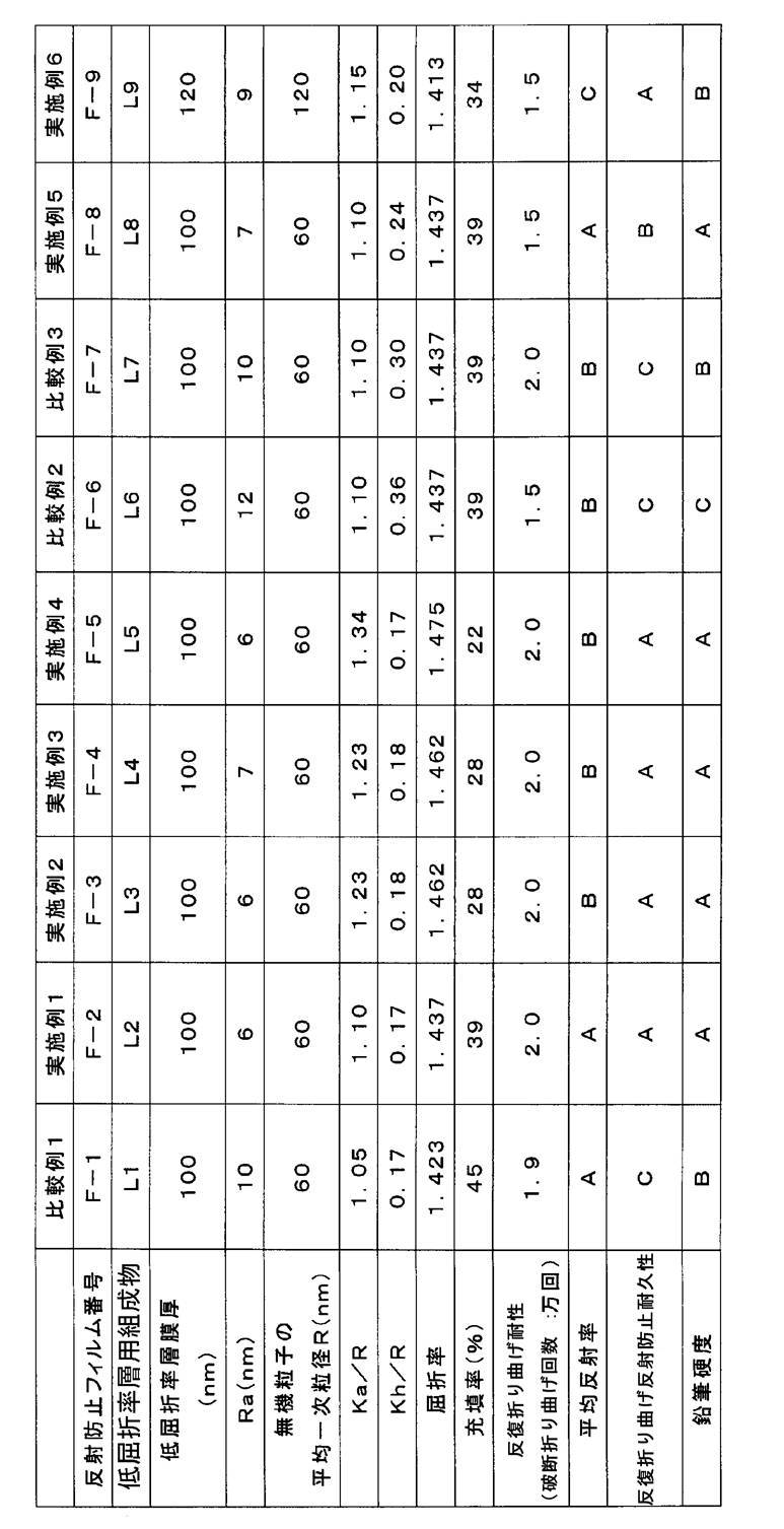
- Table 2 The results are shown in Table 2.
- Table 2 the filling rate of the inorganic particles in the low refractive index layer is also shown.
- the filling rate of the inorganic particles is determined by calculating the projected area of the inorganic particles in the low refractive index layer with respect to the transmission electron microscope image of the cross section obtained by cutting the antireflection film in the thickness direction. It was calculated by calculating the value divided by.
- the antireflection films of the examples of the present invention are excellent in repeated folding resistance, excellent in antireflection properties, and the decrease in antireflection properties after repeated folding is suppressed (for repeated bending antireflection durability). It is understood that it is excellent. Moreover, it turned out that it is excellent also in pencil hardness.
Landscapes
- Physics & Mathematics (AREA)
- General Physics & Mathematics (AREA)
- Optics & Photonics (AREA)
- Nonlinear Science (AREA)
- Mathematical Physics (AREA)
- Chemical & Material Sciences (AREA)
- Crystallography & Structural Chemistry (AREA)
- Surface Treatment Of Optical Elements (AREA)
- Polarising Elements (AREA)
- Laminated Bodies (AREA)
- Devices For Indicating Variable Information By Combining Individual Elements (AREA)
Abstract
Description
本発明の課題は、反射防止性及び反復折り曲げ耐性に優れ、かつ反復折り曲げ後の反射防止性の低下が少ない反射防止フィルム、上記反射防止フィルムを有する偏光板、画像表示装置、及び反射防止物品を提供することである。
基材と、低屈折率層とを有する反射防止フィルムであって、
上記低屈折率層は、無機粒子とバインダー樹脂とを含有し、
上記無機粒子の平均一次粒子径をRとし、粒子間隔をKとした場合、平均粒子間隔Kaが下記式(1)を満たし、粒子間隔Kの分布曲線における半値全幅Khが下記式(2)を満たし、
上記低屈折率層の上記基材とは反対側の面の表面粗さが20nm以下である、反射防止フィルム。
Ka≧1.1R … (1)
Kh≦0.25R … (2)
<2>
JIS P 8115:2001に従いMIT試験機によって測定した破断折り曲げ回数が10000回以上である<1>に記載の反射防止フィルム。
<3>
上記無機粒子の平均一次粒子径Rが200nm以下である<1>又は<2>に記載の反射防止フィルム。
<4>
上記無機粒子が中空構造を有する無機粒子である<1>~<3>のいずれか1つに記載の反射防止フィルム。
<5>
上記基材と上記低屈折率層の間にハードコート層を有する<1>~<4>のいずれか1つに記載の反射防止フィルム。
<6>
JIS K 5600-5-4:1999に従って測定した、500g荷重の鉛筆硬度が2H以上である<1>~<5>のいずれか1つに記載の反射防止フィルム。
<7>
450~650nmの波長領域における平均反射率が2%以下である<1>~<6>のいずれか1つに記載の反射防止フィルム。
<8>
上記基材が芳香族ポリアミドを含有する<1>~<7>のいずれか1つに記載の反射防止フィルム。
<9>
上記Khが0.20R以下である<1>~<8>のいずれか1つに記載の反射防止フィルム。
<10>
<1>~<9>のいずれか1つに記載の反射防止フィルムを有する偏光板。
<11>
<1>~<9>のいずれか1つに記載の反射防止フィルム又は<10>に記載の偏光板を有する画像表示装置。
<12>
<1>~<9>のいずれか1つに記載の反射防止フィルムを有する反射防止物品。
本発明の反射防止フィルムは、
基材と、低屈折率層とを有する反射防止フィルムであって、
上記低屈折率層は、無機粒子とバインダー樹脂とを含有し、
上記無機粒子の平均一次粒子径をRとし、粒子間隔をKとした場合、平均粒子間隔Kaが下記式(1)を満たし、粒子間隔Kの分布曲線における半値全幅Khが下記式(2)を満たし、
上記低屈折率層の上記基材とは反対側の面の表面粗さが20nm以下である、反射防止フィルムである。
Ka≧1.1R … (1)
Kh≦0.25R … (2)
本発明の反射防止フィルムは、基材上に直接又は他の層を介して低屈折率層を有する。
本発明の反射防止フィルムの低屈折率層に含まれる無機粒子の平均一次粒子径をRとし、粒子間隔をKとした場合、平均粒子間隔Ka及び粒子間隔Kの分布曲線における半値全幅Khは、それぞれ上記式(1)及び式(2)を満たす。ここで、粒子間隔Kは、最近接位置に存在する2つの粒子の中心間距離を表す。
本発明において、上記K、Ka、及びKhは以下のように算出した。
次に、求めた粒子間隔Kの頻度分布曲線を描き、得られた分布曲線から最大頻度を示す粒子間隔の1/2頻度の粒子間隔(K1及びK2、ただしK2>K1とする)を求め、下記式(3)よりKhを算出した。
Kh=(K2-K1)/R … (3)
低屈折率層は、波長550nmにおける屈折率が1.30~1.51であることが好ましく、1.30~1.46であることがより好ましく、1.32~1.38であることが更に好ましい。屈折率を上記範囲内とすることで反射率を抑え、膜強度を維持することができ、好ましい。
低屈折率層の基材とは反対側の面の表面粗さ(Ra)は20nm以下である。Raが20nm以下であることで、表面の凹凸に起因する視認性悪化を抑制できる。Raは、日本工業規格(JIS) B 0601:1994に従って、一般的な表面粗さ計により測定でき、例えば、触針式表面粗さ計「サーフコーダ SE3500」{(株)小坂研究所製}を用いることも好適である。Raは10nm以下であることがより好ましく、7nm以下であることが更に好ましく、5nm以下であることが特に好ましい。
本発明の低屈折率層に含有される無機粒子としては、低屈折率層の屈折率が上述の好ましい範囲となる限りは特に限定されず、フッ化マグネシウム又はシリカ等の無機粒子が挙げられる。
無機粒子は、結晶質でも、アモルファスのいずれでも良い。また無機粒子は単分散粒子が好ましい。無機粒子の形状は、球径が最も好ましいが、不定形であっても良い。
低屈折率層に含有されるバインダー樹脂は、低屈折率層の屈折率が上述の好ましい範囲となる限りは特に限定されず、例えば、特開2007-298974号公報、特開2002-317152号公報、特開2003-202406号公報、特開2003-292831号公報等に記載の公知のバインダー樹脂を用いることができる。バインダー樹脂は、1種のみを用いても、2種以上を併用してもよい。バインダー樹脂は、モノマーまたはオリゴマー(重合性化合物)の重合体であることが好ましい。重合性化合物としては、例えば後述するハードコート層の形成に用いるモノマー(a)が挙げられる。モノマーは1種でも2種以上を併用してもよい。
ここで、伸び率とは、フィルム形態の物質が初期から破断されるまでの伸び量(破断標線間距離から元の標線間距離を差し引いた距離)を元の標線間距離で除した割合を指し、下記式(4)で表される。下記式(4)中、Eは伸び率、E2は破断標線間距離、E1は元の標線間距離を示す。
E(%)=100×(E2-E1)/E1 … (4)
本発明においては、JIS K 6251:1993に従って測定した破断標線間距離値を用いて伸び率を算出した。
低屈折率層は、低屈折率層形成用塗布組成物を用いて、塗布により形成されることが好ましい。
低屈折率層形成用塗布組成物は、好ましくは上記無機粒子、上記バインダー樹脂を形成する重合性化合物及び溶剤を含有する。この際、低屈折率層形成用塗布組成物の固形分濃度は、用途に応じて適宜選択されるが、一般的には0.01~60質量%程度であり、好ましくは0.5~50質量%、特に好ましくは1~20質量%程度とするのが良い。
重合開始剤としては特に限定されず、公知の重合開始剤を用いることができる。
重合開始剤としては、たとえば、後述するハードコート層の形成において用いることができる重合開始剤が挙げられる。
重合開始剤の添加量としては、特に限定はないが、低屈折率層形成組成物中の全固形分に対して0.1~15質量%が好ましく、0.5~10質量%であることがより好ましく、1~5質量%であることが特に好ましい。
低屈折率層用塗布液組成物に含まれる溶媒としては、バインダー樹脂を形成する重合性化合物が沈殿を生じることなく、均一に溶解または分散されるものであれば特に制限はなく、1種でも、2種類以上の溶媒を併用することもできる。好ましい例としては、ケトン類(アセトン、メチルエチルケトン、メチルイソブチルケトン等)、エステル類(酢酸エチル、酢酸ブチル、プロピレングリコールモノメチルエーテルアセテート等)、エーテル類(テトラヒドロフラン、1,4-ジオキサン等)、アルコール類(メタノール、エタノール、イソプロピルアルコール、ブタノール、エチレングリコール、等)、芳香族炭化水素類(トルエン、キシレン等)などを挙げることができる。
また、防汚性、耐水性、耐薬品性、滑り性等の特性を付与する目的で、公知のシリコーン系あるいはフッ素系の防汚剤、滑り剤等を適宜添加することもできる。これらの添加剤を添加する場合には低屈折率層全固形分の0~20質量%の範囲で添加されることが好ましく、より好ましくは0~10質量%の範囲で添加される場合であり、特に好ましくは0~5質量%の場合である。
低屈折率層は、無機粒子、バインダー樹脂を形成する重合性化合物、その他所望により含有される任意成分を溶解あるいは分散させた塗布組成物を塗布と同時、または塗布、乾燥後に電離放射線照射(例えば光照射、電子線ビーム照射等が挙げられる。)、又は加熱することによる架橋反応、又は重合反応により硬化して、形成することが好ましい。
低屈折率層の膜厚は、200nm以下であることが好ましく、50nm~120nmであることがより好ましく、80~120nmであることが更に好ましい。
本発明の反射防止フィルムの基材は、可視光領域の透過率が70%以上であることが好ましく、80%以上であることがより好ましい。
基材はポリマー樹脂を含むことが好ましい。
ポリマー樹脂としては、光学的な透明性、機械的強度、熱安定性、などに優れるポリマーが好ましい。
基材は、上記のポリマー樹脂を更に柔軟化する素材を含有しても良い。柔軟化素材とは、破断折り曲げ回数を向上させる化合物を指し、柔軟化素材としては、ゴム質弾性体、脆性改良剤、可塑剤、スライドリングポリマー等を用いることが出来る。
柔軟化素材として具体的には、特開2016-167043号公報における段落番号[0051]~[0114]に記載の柔軟化素材を好適に用いることができる。
基材には、用途に応じた種々の添加剤(例えば、紫外線吸収剤、マット剤、酸化防止剤、剥離促進剤、レターデーション(光学異方性)調節剤、など)を添加できる。それらは固体でもよく油状物でもよい。すなわち、その融点又は沸点において特に限定されるものではない。また添加剤を添加する時期は基材を作製する工程において何れの時点で添加しても良く、素材調製工程に添加剤を添加し調製する工程を加えて行ってもよい。更にまた、各素材の添加量は機能が発現する限りにおいて特に限定されない。
その他の添加剤としては、特開2016-167043号公報における段落番号[0117]~[0122]に記載の添加剤を好適に用いることができる。
基材は、熱可塑性のポリマー樹脂を熱溶融して製膜しても良いし、ポリマーを均一に溶解した溶液から溶液製膜(ソルベントキャスト法)によって製膜しても良い。熱溶融製膜の場合は、上述の柔軟化素材及び種々の添加剤を、熱溶融時に加えることができる。一方、基材を溶液製膜法で作製する場合は、ポリマー溶液(以下、ドープともいう)には、各調製工程において上述の柔軟化素材及び種々の添加剤を加えることができる。またその添加する時期はドープ作製工程において何れでも添加しても良いが、ドープ調製工程の最後の調製工程に添加剤を添加し調製する工程を加えて行ってもよい。
基材の厚みは、100μm以下であることがより好ましく、60μm以下であることが更に好ましく、50μm以下が最も好ましい。基材の厚みが薄くなれば、折れ曲げ時の表面と裏面の曲率差が小さくなり、クラック等が発生し難くなり、複数回の折れ曲げでも、基材の破断が生じなくなる。一方、基材取り扱いの容易さの観点から基材の厚みは10μm以上であることが好ましく、15μm以上であることがより好ましい。反射防止フィルムが組み込まれる画像表示装置の薄型化の観点からは、反射防止フィルムの総厚は、70μm以下であることが好ましく、50μm以下であることが更に好ましい。
本発明の反射防止フィルムは、上記基材と上記低屈折率層の間に、その他の層を有していてもよい。その他の層としては、ハードコート層を有することが好ましく、基材とハードコート層は接していてもよいし、基材とハードコート層の間に別層を有していてもよい。
本発明の反射防止フィルムには、フィルムの物理的強度を付与するために、ハードコート層を設けることができる。好ましくは、ハードコート層上に低屈折率層が設けられると、鉛筆引掻き試験などの耐擦傷性面が強くなり、好ましい。ハードコート層は、二層以上の積層から構成されてもよい。
ハードコート層の波長550nmにおける屈折率は1.56以上であることが好ましく、1.68以上1.84以下であることが好ましく、1.71以上1.81以下であることがより更に好ましい。
ハードコート層は樹脂を含有することが好ましく、上記樹脂はモノマー(重合性化合物)の重合体であることが好ましい。
モノマーは1種でも2種以上を併用してもよい。
モノマーは(メタ)アクリロイル基、ビニル基、スチリル基、アリル基等の不飽和の重合性官能基を有することが好ましく、中でも、(メタ)アクリロイル基を有することが好ましい。
ハードコート層の樹脂を形成するためのモノマーとして、モノマー(「モノマー(a)」とも呼ぶ。)を用いることも好ましい。このようなモノマーの具体例としては、ネオペンチルグリコールアクリレート、1,6-ヘキサンジオール(メタ)アクリレート、プロピレングリコールジ(メタ)アクリレート等のアルキレングリコールの(メタ)アクリル酸ジエステル類;
トリエチレングリコールジ(メタ)アクリレート、ジプロピレングリコールジ(メタ)アクリレート、ポリエチレングリコールジ(メタ)アクリレート、ポリプロピレングリコールジ(メタ)アクリレート等のポリオキシアルキレングリコールの(メタ)アクリル酸ジエステル類;
ペンタエリスリトールジ(メタ)アクリレート等の多価アルコールの(メタ)アクリル酸ジエステル類;
2,2-ビス{4-(アクリロキシ・ジエトキシ)フェニル}プロパン、2-2-ビス{4-(アクリロキシ・ポリプロポキシ)フェニル}プロパン等のエチレンオキシドあるいはプロピレンオキシド付加物の(メタ)アクリル酸ジエステル類;等を挙げることができる。
例えば、ペンタエリスリトールテトラ(メタ)アクリレート、ペンタエリスリトールトリ(メタ)アクリレート、トリメチロールプロパントリ(メタ)アクリレート、エチレンオキサイド(EO)変性トリメチロールプロパントリ(メタ)アクリレート、プロピレンオキサイド(PO)変性トリメチロールプロパントリ(メタ)アクリレート、EO変性リン酸トリ(メタ)アクリレート、トリメチロールエタントリ(メタ)アクリレート、ジトリメチロールプロパンテトラ(メタ)アクリレート、ジペンタエリスリトールテトラ(メタ)アクリレート、ジペンタエリスリトールペンタ(メタ)アクリレート、ジペンタエリスリトールヘキサ(メタ)アクリレート、ペンタエリスリトールヘキサ(メタ)アクリレート、1,2,3-クロヘキサンテトラメタクリレート、ポリウレタンポリアクリレート、ポリエステルポリアクリレート、カプロラクトン変性トリス(アクリロキシエチル)イソシアヌレート等が挙げられる。
モノマーとして、フルオレン骨格、ジナフトチオフェン骨格、ナフタレン骨格、アントラセン骨格、ベンゾトリアゾール骨格、トリアジン骨格、ベンゾフェノン骨格、メロシアニン骨格、ベンゾオキサゾール骨格、ベンゾチオール骨格、トリフェニレン骨格、シンナモイル骨格、ビスフェノールS骨格、及びトラン骨格から選ばれる少なくとも1種の骨格を有する化合物(「モノマー(b)」とも呼ぶ。)を含むことも好ましい。
モノマー(b)を用いることで、ハードコート層の屈折率を高く調整することができる。モノマー(b)の具体例としては、特開2007-91876号公報の段落0029~0046に記載の一般式(I)~(VI)で表される化合物、特開2014-34596号公報の段落0113~0115に記載のフルオレン化合物、特開2014-80572号公報の一般式(1)で表される縮合環含有化合物(好ましくは同公報の一般式(3)で表される縮合環含有化合物)、特開2013-253161号公報の段落0016に記載の化合物、特開2006-301614号公報の段落0025~0153に記載の化合物、特開2007-108732号公報の段落0020~0122に記載の化合物、特開2010-244038号公報の段落0012~0108に記載の化合物等が挙げられる。
モノマー(b)としては、特に、フルオレン骨格、ジナフトチオフェン骨格、ナフタレン骨格、及びアントラセン骨格から選ばれる少なくとも1種の骨格を有する化合物が好ましく、フルオレン骨格を有する化合物が最も好ましい。
ハードコート層は無機粒子を含有してもよい。
無機粒子としては、金属(たとえば、Ti、Zr、In、Zn、Sn、Sb、及びAlなど)の酸化物の粒子であることが好ましく、屈折率の観点から、酸化ジルコニウム粒子又は酸化チタン粒子であることがより好ましく、酸化チタン粒子を平均一次粒子径10nm未満にすると光活性が強まり、周囲の有機物を分解し易くなり得る観点から、酸化ジルコニウム粒子(ジルコニア粒子)が最も好ましい。
ハードコート層中の無機粒子の含有率を変化させることで屈折率を調整することができる。
ハードコート層中の無機粒子の含有率は、ハードコート層全体に対して、5~80体積%であることが好ましく、10~60体積%であることがより好ましく、20~50体積%であることが更に好ましい。無機粒子の含有率が5体積%以上であれば、ハードコート層の屈折率を高くすることができ、80体積%以下であれば膜を形成しやすい。
ハードコート層中の無機粒子の、質量%に換算したときの好適含有率は、無機粒子の比重によって変わり、例えば無機粒子として酸化ジルコニウム粒子を用いる場合の含有率は、ハードコート層全体に対して、21~95質量%であることが好ましく、36~88質量%であることがより好ましく、56~83質量%であることが更に好ましい。
無機粒子の平均一次粒子径は、1~80nmであることが好ましく、1~40nmであることがより好ましく、2~20nmであることが更に好ましい。
また、無機粒子は後述する樹脂をバインダー成分としてハードコート層中に含有されることが好ましく、ハードコート層中のバインダー成分との密着性を向上させるために、重合性基を有する化合物で修飾して、無機粒子の表面に重合性基を付与することが好ましい。
ハードコート層は、基材上に、ハードコート層形成用組成物を塗布する工程、及びモノマーを重合させる工程を含む製造方法により作製されることが好ましい。ハードコート層形成用組成物は、前述のモノマー又は無機粒子に加えて、有機溶剤を含有することが好ましい。
ここで、アルコール類としては、例えば、メタノール、エタノール、イソプロピルアルコール、イソブタノール、n―ブタノール、tert―ブタノール、エトキシエタノール、ブトキシエタノール、ジエチレングリコールモノエチルエーテル、ベンジルアルコール、フェネチルアルコール等を挙げることができる。ケトン類としては、例えば、アセトン、メチルエチルケトン、メチルイソブチルケトン、シクロヘキサノン等を挙げることができる。エーテル類としては、例えば、ジブチルエーテル、プロピレングリコールモノエチルエーテルアセテート等を挙げることができる。エステル類としては、例えば、酢酸エチル、酢酸ブチル、乳酸エチル等を挙げることができる。炭化水素類としては、例えば、トルエン、キシレン等を挙げることができる。アミド類としては、例えば、ホルムアミド、ジメチルアセトアミド、N―メチルピロリドン等を挙げることができる。中でも、イソプロピルアルコール、エトキシエタノール、ブトキシエタノール、ジエチレングリコールモノエチルエーテル、メチルエチルケトン、メチルイソブチルケトン、シクロヘキサノン、プロピレングリコールモノエチルエーテルアセテート、酢酸ブチル、乳酸エチル等が好ましい。
ハードコート層形成用組成物は、重合開始剤を含んでいてもよい。
モノマーが光重合性化合物である場合は、光重合開始剤を含むことが好ましい。
光重合開始剤としては、アセトフェノン類、ベンゾイン類、ベンゾフェノン類、ホスフィンオキシド類、ケタール類、アントラキノン類、チオキサントン類、アゾ化合物、過酸化物類、2,3-ジアルキルジオン化合物類、ジスルフィド化合物類、フルオロアミン化合物類、芳香族スルホニウム類、ロフィンダイマー類、オニウム塩類、ボレート塩類、活性エステル類、活性ハロゲン類、無機錯体、クマリン類などが挙げられる。光重合開始剤の具体例、及び好ましい態様、市販品などは、特開2009-098658号公報の段落[0133]~[0151]に記載されており、本発明においても同様に好適に用いることができる。
「最新UV硬化技術」{(株)技術情報協会}(1991年)、p.159、及び、「紫外線硬化システム」加藤清視著(平成元年、総合技術センター発行)、p.65~148にも種々の例が記載されており本発明に有用である。
ハードコート層形成用組成物中の重合開始剤の含有率は、ハードコート層形成用組成物中の全固形分に対して、0.5~8質量%が好ましく、1~5質量%がより好ましい。
(破断折り曲げ回数)
本発明の反射防止フィルムは、JIS P 8115:2001に従いMIT試験機によって測定した破断折り曲げ回数が10000回以上であることが好ましい。なお、本発明において、破断折り曲げ回数の測定は、反射防止フィルムの基材が内側となるように折り曲げて行った。
本発明の反射防止フィルムは、反射防止性の観点から、450~650nmの波長領域における平均反射率が2%以下であることが好ましく、1.5%以下であることがより好ましい。
本発明の反射防止フィルムは、膜強度の観点から、JIS K 5600-5-4:1999に従って測定した500g荷重の鉛筆硬度が2H以上であることが好ましく、3H以上であることがより好ましい。
本発明の反射防止フィルムを用いた偏光板保護フィルムは、偏光子と貼り合せて偏光板とすることができ、液晶表示装置などに好適に用いることができる。
偏光板は、偏光子と、偏光子を保護する少なくとも1枚の保護フィルムとを有する偏光板であって、保護フィルムの少なくとも1枚が本発明の反射防止フィルムであることが好ましい。
本発明の反射防止フィルム又は偏光板を画像表示装置に適用することもできる。
画像表示装置としては、陰極線管を利用した表示装置、プラズマディスプレイパネル、エレクトロルミネッセンスディスプレイ、蛍光表示ディスプレイ、フィールドエミッションディスプレイ、及び液晶表示装置を挙げることができ、特に液晶表示装置が好ましい。
一般的に、液晶表示装置は、液晶セル及びその両側に配置された2枚の偏光板を有し、液晶セルは、2枚の電極基板の間に液晶を担持している。更に、光学異方性層が、液晶セルと一方の偏光板との間に一枚配置されるか、又は液晶セルと双方の偏光板との間に2枚配置されることもある。液晶セルは、TN(Twisted Nematic)モード、VA(Vertically Aligned)モード、OCB(Optically Compensatory Bend)モード、IPS(In-Plane Switching)モードなど様々な駆動方式の液晶セルが適用できる。
本発明の反射防止フィルムは、画像表示装置以外にも適用することができ、たとえば各種の物品に本発明の反射防止フィルムを貼合することで、反射防止機能を付与した反射防止物品とすることができる。
下記に示す通りに、基材上に、ハードコート層形成用組成物(塗布液)を用いてハードコート層を形成し、次にハードコート層上に低屈折率層を形成して反射防止フィルムを作製した。
攪拌機を備えた重合槽にN-メチル-2-ピロリドン674.7kg、無水臭化リチウム10.6g(シグマアルドリッチジャパン社製)、2,2’-ジトリフルオロメチル-4,4’-ジアミノビフェニル(東レファインケミカル社製「TFMB」)33.3g、4,4’-ジアミノジフェニルスルフォン(和歌山精化株式会社製「44DDS」)2.9gを入れ窒素雰囲気下、15℃に冷却、攪拌しながら300分かけてテレフタル酸ジクロライド(東京化成社製)18.5g、4,4’-ビフェニルジカルボニルクロライド(東レファインケミカル社製「4BPAC」)6.4gを4回に分けて添加した。60分間攪拌した後、反応で発生した塩化水素を炭酸リチウムで中和してポリマー溶液を得た。
上記で得られたポリマー溶液の一部を最終のフィルム厚みが25μmになるようにTダイを用いて120℃のエンドレスベルト上に流延し、ポリマー濃度が40質量%になる様に乾燥してエンドレスベルトから剥離した。次に溶媒を含んだフィルムを40℃の大気中でMD(Machine Direction)方向に1.1倍延伸し、50℃の水で水洗して溶媒を除去した。さらに340℃の乾燥炉でTD(Transverse Direction)方向に1.2倍延伸し、芳香族ポリアミドからなる、厚み25μmの基材フィルムS-1を得た。基材フィルムS-1のJIS P 8115:2001に従いMIT試験機によって測定した破断折り曲げ回数は2.5万回であった。
下記組成で、各々の成分をミキシングタンクに投入し、攪拌して、孔径0.4μmのポリプロピレン製フィルターで濾過して、ハードコート層形成用組成物HT-1を調製した。
硬化性化合物A1:1.59質量部
硬化性化合物A2:1.59質量部
ジルコニア分散物ZB:84.42質量部
光重合開始剤J1:1.50質量部
トルエン:10.91質量部
硬化性化合物A2:ペンタエリスリトールテトラアクリレートとペンタエリスリトールトリアクリレートの混合物(商品名KAYARAD PET30、日本化薬(株)製)
ジルコニア分散物ZB:平均一次粒子径20nmのジルコニア粒子含有分散物、トルエン30質量%溶液(CIKナノテック(株)製)
光重合開始剤J1:IRGACURE(登録商標)184(BASF(株)製)
シリカ系中空微粒子分散ゾル(触媒化成工業(株)製:商品名スルーリア1420、平均一次粒子径60nm、濃度20.5質量%、分散媒:イソプロパノール)500質量部に、γ-アクリロイルオキシプロピルトリメトキシシラン33.5質量部、ジイソプロポキシアルミニウムエチルアセテート1.51質量部、およびメチルエチルケトン500質量部を加えて混合した後に、イオン交換水9質量部を加えた。この混合液を60℃で10時間反応させた後に室温(23℃)まで冷却し、アセチルアセトン1.8質量部を添加して分散物を得た。その後、シリカの含率がほぼ一定になるようにシクロヘキサノンを添加しながら、圧力133.232Paで減圧蒸留による溶媒置換を行い、最後に濃度調整により固形分濃度18.3質量%の重合性官能基を有する有機珪素化合物で表面修飾した中空シリカ粒子分散物R-1を作製した。
シリカ粒子分散物R-1の調製におけるシリカ系中空微粒子分散ゾル(商品名スルーリア1420)を、触媒化成工業(株)製:商品名スルーリア1420-120(平均一次粒子径120nm、濃度20.5質量%、分散媒:イソプロパノール)に変更したこと以外は同様にして、固形分濃度17.9質量%の中空シリカ粒子分散物R-3を作製した。
下記表1に記載の組成(質量部)となるように、各々の成分をミキシングタンクに投入し、攪拌して、孔径0.4μmのポリプロピレン製フィルターで濾過して、低屈折率層用組成物L1~L9を調製した。

シリカ分散物R-2:シリカ系中空微粒子分散ゾル(触媒化成工業(株)製、商品名スルーリア1420、平均一次粒子径60nm)
滑り剤M1:アクリロイル変性シリコーン系滑り剤(信越化学工業(株)製、商品名X-22-164A)
PGMEA:プロピレングリコールモノメチルエーテルアセテート
得られた基材S-1上に、上述のハードコート層形成用組成物HT-1を、グラビアコーターを用い、ハードコート層厚みが3μmとなるように調整して塗布した。塗布した組成物を、120℃で乾燥した後、酸素濃度が100ppm以下の雰囲気になるように窒素パージしながら160W/cmの空冷メタルハライドランプ(アイグラフィックス(株)製)を用いて、照射量30mJ/cm2の紫外線照射により硬化させ、ハードコートフィルムを作製した。
得られたハードコートフィルムのハードコート層上に、低屈折率層用組成物L1を、グラビアコーターを用いて塗布した。塗布した組成物を、60℃で乾燥した後、酸素濃度が100ppm以下の雰囲気になるように窒素パージしながら160W/cmの空冷メタルハライドランプ(アイグラフィックス(株)製)を用いて、照射量300mJ/cm2の紫外線照射により硬化させ、反射防止フィルムF-1を作製した。低屈折率層の膜厚は100nmであった。
(反復折り曲げ耐性)
耐折度試験機(テスター産業(株)製、MIT、BE-201型、折り曲げ半径0.4mm)を用いて、25℃、相対湿度65%の状態に1時間静置させた、幅15mm、長さ80mmの反射防止フィルム試料を準備し、基材が内側になるように折り曲げ、荷重500gの条件で、JIS P 8115:2001に準拠して測定し、破断するまでの回数(破断折り曲げ回数)で評価した。
反射防止フィルムの裏面(基材フィルムの低屈折率層側界面とは反対の表面)を、サンドペーパーで粗面化した後に黒色インクで処理し、裏面反射をなくした状態で、分光光度計V-550(日本分光(株)製)を用いて450~650nmの波長領域で、入射角5°における鏡面反射率を測定し、平均反射率を算出して下記基準で反射防止性を評価した。
A:鏡面反射率が1.0%未満
B:鏡面反射率が1.0%以上1.5%未満
C:鏡面反射率が1.5%以上2%以下
上述の反復折り曲げ耐性の折り曲げ試験における10000回折り曲げ後の各反射防止フィルム試料について、上述の方法で折り曲げ部の平均反射率を測定した。そして、折り曲げ部の平均反射率と、折り曲げ前の平均反射率との差を算出し、反復折り曲げ反射防止耐久性を評価した。
A:反射率差が0.1%以内(折り曲げ部と非折り曲げ部に見た目の差が無い)
B:反射率差が0.1%より大きく、0.3%以内(僅かに見た目の差があるが気にならない)
C:反射率差が0.3%超(明らかに見た目に差があり気になる)
各試料に対し、JIS K 5600-5-4:1999に記載の鉛筆硬度評価を荷重500gの条件で行い、その後消しゴムにて鉛筆跡を除去した。各試料を温度25℃、相対湿度60%で3時間調湿した後、JIS S 6006:2007に規定する試験用鉛筆を用いて硬度評価を実施し、更に温度25℃、相対湿度60%の環境下で、試験後3時間放置後に下記の基準で評価した。
A:2H試験後に引っかき傷跡または色味変化が観察されない。
B:2H試験後に引っかき傷跡は観察されないが、色味変化が観察される。
C:2H試験後に引っかき傷跡及び色味変化が観察される。
多波長アッベ屈折計DR-M4(株式会社アタゴ製、製品名)を用い、反射防止フィルムの低屈折率層の波長550nmに対する屈折率を測定した。
なお、表2には、低屈折率層における無機粒子の充填率についても併記する。無機粒子の充填率は、反射防止フィルムを厚み方向に切削して得られた断面の透過型電子顕微鏡画像に対し、低屈折率層内の無機粒子の投影面積を求め、低屈折率層全面積で除した値を算出することで求めた。
Claims (12)
- 基材と、低屈折率層とを有する反射防止フィルムであって、
前記低屈折率層は、無機粒子とバインダー樹脂とを含有し、
前記無機粒子の平均一次粒子径をRとし、粒子間隔をKとした場合、平均粒子間隔Kaが下記式(1)を満たし、粒子間隔Kの分布曲線における半値全幅Khが下記式(2)を満たし、
前記低屈折率層の前記基材とは反対側の面の表面粗さが20nm以下である、反射防止フィルム。
Ka≧1.1R … (1)
Kh≦0.25R … (2) - JIS P 8115:2001に従いMIT試験機によって測定した破断折り曲げ回数が10000回以上である請求項1に記載の反射防止フィルム。
- 前記無機粒子の平均一次粒子径Rが200nm以下である請求項1又は2に記載の反射防止フィルム。
- 前記無機粒子が中空構造を有する無機粒子である請求項1~3のいずれか1項に記載の反射防止フィルム。
- 前記基材と前記低屈折率層の間にハードコート層を有する請求項1~4のいずれか1項に記載の反射防止フィルム。
- JIS K 5600-5-4:1999に従って測定した、500g荷重の鉛筆硬度が2H以上である請求項1~5のいずれか1項に記載の反射防止フィルム。
- 450~650nmの波長領域における平均反射率が2%以下である請求項1~6のいずれか1項に記載の反射防止フィルム。
- 前記基材が芳香族ポリアミドを含有する請求項1~7のいずれか1項に記載の反射防止フィルム。
- 前記Khが0.20R以下である請求項1~8のいずれか1項に記載の反射防止フィルム。
- 請求項1~9のいずれか1項に記載の反射防止フィルムを有する偏光板。
- 請求項1~9のいずれか1項に記載の反射防止フィルム又は請求項10に記載の偏光板を有する画像表示装置。
- 請求項1~9のいずれか1項に記載の反射防止フィルムを有する反射防止物品。
Priority Applications (4)
| Application Number | Priority Date | Filing Date | Title |
|---|---|---|---|
| CN201780066161.2A CN109891271B (zh) | 2016-10-25 | 2017-10-02 | 防反射膜、偏振片、图像显示装置及防反射物品 |
| JP2018547507A JP6745348B2 (ja) | 2016-10-25 | 2017-10-02 | 反射防止フィルム、偏光板、画像表示装置、及び反射防止物品 |
| KR1020197011663A KR102194501B1 (ko) | 2016-10-25 | 2017-10-02 | 반사 방지 필름, 편광판, 화상 표시 장치, 및 반사 방지 물품 |
| US16/386,711 US20190243030A1 (en) | 2016-10-25 | 2019-04-17 | Antireflection film, polarizing plate, image display device, and antireflection product |
Applications Claiming Priority (2)
| Application Number | Priority Date | Filing Date | Title |
|---|---|---|---|
| JP2016-209058 | 2016-10-25 | ||
| JP2016209058 | 2016-10-25 |
Related Child Applications (1)
| Application Number | Title | Priority Date | Filing Date |
|---|---|---|---|
| US16/386,711 Continuation US20190243030A1 (en) | 2016-10-25 | 2019-04-17 | Antireflection film, polarizing plate, image display device, and antireflection product |
Publications (1)
| Publication Number | Publication Date |
|---|---|
| WO2018079202A1 true WO2018079202A1 (ja) | 2018-05-03 |
Family
ID=62023366
Family Applications (1)
| Application Number | Title | Priority Date | Filing Date |
|---|---|---|---|
| PCT/JP2017/035834 Ceased WO2018079202A1 (ja) | 2016-10-25 | 2017-10-02 | 反射防止フィルム、偏光板、画像表示装置、及び反射防止物品 |
Country Status (5)
| Country | Link |
|---|---|
| US (1) | US20190243030A1 (ja) |
| JP (1) | JP6745348B2 (ja) |
| KR (1) | KR102194501B1 (ja) |
| CN (1) | CN109891271B (ja) |
| WO (1) | WO2018079202A1 (ja) |
Citations (5)
| Publication number | Priority date | Publication date | Assignee | Title |
|---|---|---|---|---|
| JP4778634B2 (ja) * | 2001-07-04 | 2011-09-21 | ナトコ株式会社 | 反射防止フィルム |
| JP2014056066A (ja) * | 2012-09-12 | 2014-03-27 | Toppan Printing Co Ltd | 反射防止フィルムおよびその製造方法 |
| JP2015004937A (ja) * | 2013-06-24 | 2015-01-08 | 凸版印刷株式会社 | 反射防止フィルム |
| JP2016071264A (ja) * | 2014-09-30 | 2016-05-09 | 富士フイルム株式会社 | 光学フィルム、偏光板保護フィルム、偏光板、及び液晶表示装置 |
| JP2016167043A (ja) * | 2015-03-04 | 2016-09-15 | 富士フイルム株式会社 | 反射防止物品、偏光板、カバーガラス、及び画像表示装置、並びに反射防止物品の製造方法 |
Family Cites Families (10)
| Publication number | Priority date | Publication date | Assignee | Title |
|---|---|---|---|---|
| JP2003344603A (ja) | 2002-05-23 | 2003-12-03 | Sony Corp | 反射防止膜 |
| JP2007017946A (ja) * | 2005-06-10 | 2007-01-25 | Konica Minolta Opto Inc | 反射防止フィルム、反射防止フィルムの製造方法、偏光板及び液晶表示装置 |
| KR20100112740A (ko) * | 2009-04-10 | 2010-10-20 | 도레이첨단소재 주식회사 | 저반사 필름 |
| US20150064405A1 (en) * | 2011-04-20 | 2015-03-05 | Corning Incorporated | Low reflectivity articles and methods thereof |
| JP6186294B2 (ja) * | 2014-03-07 | 2017-08-23 | 富士フイルム株式会社 | 反射防止フィルム、偏光板、画像表示装置、及び反射防止フィルムの製造方法 |
| WO2015152308A1 (ja) * | 2014-03-31 | 2015-10-08 | 富士フイルム株式会社 | 反射防止フィルム、偏光板、カバーガラス、及び画像表示装置、並びに反射防止フィルムの製造方法 |
| CN106164713B (zh) * | 2014-03-31 | 2018-01-09 | 富士胶片株式会社 | 防反射膜、偏振片、护罩玻璃、图像显示装置及防反射膜的制造方法 |
| JP2016075869A (ja) | 2014-10-09 | 2016-05-12 | エルジー ディスプレイ カンパニー リミテッド | フレキシブル表示装置 |
| US9903982B2 (en) * | 2015-03-04 | 2018-02-27 | Fujifilm Corporation | Antireflection article, polarizing plate, cover glass and image display device, and manufacturing method of antireflection article |
| JP6460471B2 (ja) * | 2015-03-16 | 2019-01-30 | 大日本印刷株式会社 | 積層体、偏光板、および画像表示装置 |
-
2017
- 2017-10-02 WO PCT/JP2017/035834 patent/WO2018079202A1/ja not_active Ceased
- 2017-10-02 CN CN201780066161.2A patent/CN109891271B/zh active Active
- 2017-10-02 JP JP2018547507A patent/JP6745348B2/ja active Active
- 2017-10-02 KR KR1020197011663A patent/KR102194501B1/ko active Active
-
2019
- 2019-04-17 US US16/386,711 patent/US20190243030A1/en not_active Abandoned
Patent Citations (5)
| Publication number | Priority date | Publication date | Assignee | Title |
|---|---|---|---|---|
| JP4778634B2 (ja) * | 2001-07-04 | 2011-09-21 | ナトコ株式会社 | 反射防止フィルム |
| JP2014056066A (ja) * | 2012-09-12 | 2014-03-27 | Toppan Printing Co Ltd | 反射防止フィルムおよびその製造方法 |
| JP2015004937A (ja) * | 2013-06-24 | 2015-01-08 | 凸版印刷株式会社 | 反射防止フィルム |
| JP2016071264A (ja) * | 2014-09-30 | 2016-05-09 | 富士フイルム株式会社 | 光学フィルム、偏光板保護フィルム、偏光板、及び液晶表示装置 |
| JP2016167043A (ja) * | 2015-03-04 | 2016-09-15 | 富士フイルム株式会社 | 反射防止物品、偏光板、カバーガラス、及び画像表示装置、並びに反射防止物品の製造方法 |
Also Published As
| Publication number | Publication date |
|---|---|
| KR102194501B1 (ko) | 2020-12-23 |
| JPWO2018079202A1 (ja) | 2019-08-08 |
| KR20190052124A (ko) | 2019-05-15 |
| US20190243030A1 (en) | 2019-08-08 |
| JP6745348B2 (ja) | 2020-08-26 |
| CN109891271B (zh) | 2021-04-20 |
| CN109891271A (zh) | 2019-06-14 |
Similar Documents
| Publication | Publication Date | Title |
|---|---|---|
| JP5750231B2 (ja) | 塗布組成物、光学フィルム、偏光板、及び画像表示装置 | |
| JP5983410B2 (ja) | 光学積層体、偏光板及び画像表示装置 | |
| JP5529320B2 (ja) | ハードコート層形成用組成物、ハードコートフィルム、光学素子および画像表示装置 | |
| KR100775728B1 (ko) | 반사 방지 재료 및 그것을 이용한 편광 필름 | |
| US20080026182A1 (en) | Hard-coated film, polarizing plate and image display including the same, and method of manufacturing hard-coated film | |
| JP2006058574A (ja) | ハードコートフィルム | |
| KR101971011B1 (ko) | 하드 코트 필름, 화상 표시 소자의 전면판, 저항막식 터치 패널, 정전 용량식 터치 패널 및 화상 표시 장치 | |
| JP2021515273A (ja) | 反射防止フィルム、偏光板、およびディスプレイ装置 | |
| JP2020536288A (ja) | 反射防止フィルム、偏光板およびディスプレイ装置 | |
| US20120194907A1 (en) | Antiglare film, polarizing plate, image display, and method for producing the antiglare film | |
| JP7198946B2 (ja) | 光学積層体、偏光板、画像表示装置、抵抗膜式タッチパネル及び静電容量式タッチパネル | |
| JP2009258214A (ja) | 表示装置 | |
| KR20160037117A (ko) | 광학 필름 및 그것을 구비한 편광판, 액정 표시 장치, 및 광학 필름의 제조 방법 | |
| JP5490487B2 (ja) | 光学積層体 | |
| JP5753285B2 (ja) | 光学積層体 | |
| US11644604B2 (en) | Optical film, polarizing plate, and image display device | |
| JP2008107432A (ja) | 偏光板およびそれを用いた画像表示装置 | |
| JP2020535462A (ja) | 反射防止フィルム、偏光板およびディスプレイ装置 | |
| JPWO2014208748A1 (ja) | 紫外線硬化型ハードコート樹脂組成物 | |
| JPWO2014208749A1 (ja) | 紫外線硬化型ハードコート樹脂組成物 | |
| JP2009091477A (ja) | 透明架橋フィルム | |
| JP2002006109A (ja) | 反射防止材料およびそれを用いた偏光フィルム | |
| JP5426329B2 (ja) | 光学積層体 | |
| JP4524150B2 (ja) | 反射防止フィルム、偏光板、画像表示装置、および反射防止フィルムの製造方法 | |
| JP6745348B2 (ja) | 反射防止フィルム、偏光板、画像表示装置、及び反射防止物品 |
Legal Events
| Date | Code | Title | Description |
|---|---|---|---|
| 121 | Ep: the epo has been informed by wipo that ep was designated in this application |
Ref document number: 17865953 Country of ref document: EP Kind code of ref document: A1 |
|
| ENP | Entry into the national phase |
Ref document number: 2018547507 Country of ref document: JP Kind code of ref document: A |
|
| ENP | Entry into the national phase |
Ref document number: 20197011663 Country of ref document: KR Kind code of ref document: A |
|
| NENP | Non-entry into the national phase |
Ref country code: DE |
|
| 122 | Ep: pct application non-entry in european phase |
Ref document number: 17865953 Country of ref document: EP Kind code of ref document: A1 |