WO2018079097A1 - レーダ装置、信号処理装置及び信号処理方法 - Google Patents
レーダ装置、信号処理装置及び信号処理方法 Download PDFInfo
- Publication number
- WO2018079097A1 WO2018079097A1 PCT/JP2017/032625 JP2017032625W WO2018079097A1 WO 2018079097 A1 WO2018079097 A1 WO 2018079097A1 JP 2017032625 W JP2017032625 W JP 2017032625W WO 2018079097 A1 WO2018079097 A1 WO 2018079097A1
- Authority
- WO
- WIPO (PCT)
- Prior art keywords
- signal
- beat signal
- transmission
- reference time
- beat
- Prior art date
- Legal status (The legal status is an assumption and is not a legal conclusion. Google has not performed a legal analysis and makes no representation as to the accuracy of the status listed.)
- Ceased
Links
Images







Classifications
-
- G—PHYSICS
- G01—MEASURING; TESTING
- G01S—RADIO DIRECTION-FINDING; RADIO NAVIGATION; DETERMINING DISTANCE OR VELOCITY BY USE OF RADIO WAVES; LOCATING OR PRESENCE-DETECTING BY USE OF THE REFLECTION OR RERADIATION OF RADIO WAVES; ANALOGOUS ARRANGEMENTS USING OTHER WAVES
- G01S13/00—Systems using the reflection or reradiation of radio waves, e.g. radar systems; Analogous systems using reflection or reradiation of waves whose nature or wavelength is irrelevant or unspecified
- G01S13/02—Systems using reflection of radio waves, e.g. primary radar systems; Analogous systems
- G01S13/06—Systems determining position data of a target
- G01S13/08—Systems for measuring distance only
- G01S13/32—Systems for measuring distance only using transmission of continuous waves, whether amplitude-, frequency-, or phase-modulated, or unmodulated
- G01S13/34—Systems for measuring distance only using transmission of continuous waves, whether amplitude-, frequency-, or phase-modulated, or unmodulated using transmission of continuous, frequency-modulated waves while heterodyning the received signal, or a signal derived therefrom, with a locally-generated signal related to the contemporaneously transmitted signal
-
- G—PHYSICS
- G01—MEASURING; TESTING
- G01S—RADIO DIRECTION-FINDING; RADIO NAVIGATION; DETERMINING DISTANCE OR VELOCITY BY USE OF RADIO WAVES; LOCATING OR PRESENCE-DETECTING BY USE OF THE REFLECTION OR RERADIATION OF RADIO WAVES; ANALOGOUS ARRANGEMENTS USING OTHER WAVES
- G01S13/00—Systems using the reflection or reradiation of radio waves, e.g. radar systems; Analogous systems using reflection or reradiation of waves whose nature or wavelength is irrelevant or unspecified
- G01S13/003—Bistatic radar systems; Multistatic radar systems
-
- G—PHYSICS
- G01—MEASURING; TESTING
- G01S—RADIO DIRECTION-FINDING; RADIO NAVIGATION; DETERMINING DISTANCE OR VELOCITY BY USE OF RADIO WAVES; LOCATING OR PRESENCE-DETECTING BY USE OF THE REFLECTION OR RERADIATION OF RADIO WAVES; ANALOGOUS ARRANGEMENTS USING OTHER WAVES
- G01S13/00—Systems using the reflection or reradiation of radio waves, e.g. radar systems; Analogous systems using reflection or reradiation of waves whose nature or wavelength is irrelevant or unspecified
- G01S13/02—Systems using reflection of radio waves, e.g. primary radar systems; Analogous systems
- G01S13/06—Systems determining position data of a target
- G01S13/42—Simultaneous measurement of distance and other co-ordinates
-
- G—PHYSICS
- G01—MEASURING; TESTING
- G01S—RADIO DIRECTION-FINDING; RADIO NAVIGATION; DETERMINING DISTANCE OR VELOCITY BY USE OF RADIO WAVES; LOCATING OR PRESENCE-DETECTING BY USE OF THE REFLECTION OR RERADIATION OF RADIO WAVES; ANALOGOUS ARRANGEMENTS USING OTHER WAVES
- G01S13/00—Systems using the reflection or reradiation of radio waves, e.g. radar systems; Analogous systems using reflection or reradiation of waves whose nature or wavelength is irrelevant or unspecified
- G01S13/88—Radar or analogous systems specially adapted for specific applications
- G01S13/93—Radar or analogous systems specially adapted for specific applications for anti-collision purposes
-
- G—PHYSICS
- G01—MEASURING; TESTING
- G01S—RADIO DIRECTION-FINDING; RADIO NAVIGATION; DETERMINING DISTANCE OR VELOCITY BY USE OF RADIO WAVES; LOCATING OR PRESENCE-DETECTING BY USE OF THE REFLECTION OR RERADIATION OF RADIO WAVES; ANALOGOUS ARRANGEMENTS USING OTHER WAVES
- G01S13/00—Systems using the reflection or reradiation of radio waves, e.g. radar systems; Analogous systems using reflection or reradiation of waves whose nature or wavelength is irrelevant or unspecified
- G01S13/88—Radar or analogous systems specially adapted for specific applications
- G01S13/93—Radar or analogous systems specially adapted for specific applications for anti-collision purposes
- G01S13/931—Radar or analogous systems specially adapted for specific applications for anti-collision purposes of land vehicles
-
- G—PHYSICS
- G01—MEASURING; TESTING
- G01S—RADIO DIRECTION-FINDING; RADIO NAVIGATION; DETERMINING DISTANCE OR VELOCITY BY USE OF RADIO WAVES; LOCATING OR PRESENCE-DETECTING BY USE OF THE REFLECTION OR RERADIATION OF RADIO WAVES; ANALOGOUS ARRANGEMENTS USING OTHER WAVES
- G01S7/00—Details of systems according to groups G01S13/00, G01S15/00, G01S17/00
- G01S7/02—Details of systems according to groups G01S13/00, G01S15/00, G01S17/00 of systems according to group G01S13/00
-
- G—PHYSICS
- G01—MEASURING; TESTING
- G01S—RADIO DIRECTION-FINDING; RADIO NAVIGATION; DETERMINING DISTANCE OR VELOCITY BY USE OF RADIO WAVES; LOCATING OR PRESENCE-DETECTING BY USE OF THE REFLECTION OR RERADIATION OF RADIO WAVES; ANALOGOUS ARRANGEMENTS USING OTHER WAVES
- G01S7/00—Details of systems according to groups G01S13/00, G01S15/00, G01S17/00
- G01S7/02—Details of systems according to groups G01S13/00, G01S15/00, G01S17/00 of systems according to group G01S13/00
- G01S7/35—Details of non-pulse systems
- G01S7/352—Receivers
-
- H—ELECTRICITY
- H01—ELECTRIC ELEMENTS
- H01Q—ANTENNAS, i.e. RADIO AERIALS
- H01Q21/00—Antenna arrays or systems
- H01Q21/06—Arrays of individually energised antenna units similarly polarised and spaced apart
- H01Q21/08—Arrays of individually energised antenna units similarly polarised and spaced apart the units being spaced along or adjacent to a rectilinear path
-
- G—PHYSICS
- G01—MEASURING; TESTING
- G01S—RADIO DIRECTION-FINDING; RADIO NAVIGATION; DETERMINING DISTANCE OR VELOCITY BY USE OF RADIO WAVES; LOCATING OR PRESENCE-DETECTING BY USE OF THE REFLECTION OR RERADIATION OF RADIO WAVES; ANALOGOUS ARRANGEMENTS USING OTHER WAVES
- G01S13/00—Systems using the reflection or reradiation of radio waves, e.g. radar systems; Analogous systems using reflection or reradiation of waves whose nature or wavelength is irrelevant or unspecified
- G01S13/88—Radar or analogous systems specially adapted for specific applications
- G01S13/93—Radar or analogous systems specially adapted for specific applications for anti-collision purposes
- G01S13/931—Radar or analogous systems specially adapted for specific applications for anti-collision purposes of land vehicles
- G01S2013/9327—Sensor installation details
- G01S2013/93271—Sensor installation details in the front of the vehicles
-
- G—PHYSICS
- G01—MEASURING; TESTING
- G01S—RADIO DIRECTION-FINDING; RADIO NAVIGATION; DETERMINING DISTANCE OR VELOCITY BY USE OF RADIO WAVES; LOCATING OR PRESENCE-DETECTING BY USE OF THE REFLECTION OR RERADIATION OF RADIO WAVES; ANALOGOUS ARRANGEMENTS USING OTHER WAVES
- G01S13/00—Systems using the reflection or reradiation of radio waves, e.g. radar systems; Analogous systems using reflection or reradiation of waves whose nature or wavelength is irrelevant or unspecified
- G01S13/88—Radar or analogous systems specially adapted for specific applications
- G01S13/93—Radar or analogous systems specially adapted for specific applications for anti-collision purposes
- G01S13/931—Radar or analogous systems specially adapted for specific applications for anti-collision purposes of land vehicles
- G01S2013/9327—Sensor installation details
- G01S2013/93272—Sensor installation details in the back of the vehicles
-
- G—PHYSICS
- G01—MEASURING; TESTING
- G01S—RADIO DIRECTION-FINDING; RADIO NAVIGATION; DETERMINING DISTANCE OR VELOCITY BY USE OF RADIO WAVES; LOCATING OR PRESENCE-DETECTING BY USE OF THE REFLECTION OR RERADIATION OF RADIO WAVES; ANALOGOUS ARRANGEMENTS USING OTHER WAVES
- G01S7/00—Details of systems according to groups G01S13/00, G01S15/00, G01S17/00
- G01S7/02—Details of systems according to groups G01S13/00, G01S15/00, G01S17/00 of systems according to group G01S13/00
- G01S7/35—Details of non-pulse systems
- G01S7/352—Receivers
- G01S7/356—Receivers involving particularities of FFT processing
-
- G—PHYSICS
- G08—SIGNALLING
- G08G—TRAFFIC CONTROL SYSTEMS
- G08G1/00—Traffic control systems for road vehicles
- G08G1/16—Anti-collision systems
Definitions
- the present disclosure relates to a radar device, a signal processing device, and a signal processing method.
- a TDMA Time-Division Multiple-Access
- FMCW Frequency-Modulated Continuous-Wave
- MIMO Multiple-Input Multiple-Output
- the FMCW method uses a chirp signal whose frequency is linearly increased or decreased over time as a transmission signal, which is emitted from the transmission antenna, and an echo signal reflected back from the target is captured by the reception antenna.
- the frequency of the local signal changes during the round-trip time until the transmitted signal is reflected back by the target and returned to the target.
- This is a method for performing distance measurement utilizing the generation of a beat signal having a frequency proportional to The TDMA FMCW MIMO system, in addition to the distance measurement based on the FMCW system, sequentially selects one antenna from the M-element transmission array antenna and transmits the chirp signal M times, and simultaneously receives the N-element reception array antenna.
- This is a method for performing angle measurement with improved azimuth resolution by using the fact that it can be regarded as a radar device that receives a virtual array antenna having M * N elements.
- the TDMA FMCW MIMO radar device is known to degrade the angle measurement accuracy due to the Doppler phase shift when the target and the radar device are moving relatively.
- a technique is disclosed in which a virtual array antenna of M * N ⁇ L elements is configured so that at least L antenna elements overlap, and a Doppler phase shift is obtained and compensated from the phase difference of beat signals received by the overlapping antenna elements. Has been.
- Non-Patent Document 1 since the Doppler phase shift of the entire virtual array antenna is compensated from beat signals received by a small number of overlapping antenna elements, the azimuth estimation accuracy is greatly affected by slight noise. Further, since the number of elements of the virtual array antenna is reduced by overlapping the antenna elements, the azimuth resolution is lowered.
- TDMA FMCW MIMO radar apparatus a new and improved radar apparatus, signal processing apparatus, and signal processing apparatus capable of compensating the Doppler phase shift of the moving target and improving the direction estimation accuracy are provided.
- a signal processing method is proposed.
- a signal processing unit that performs signal processing on the beat signal, and the transmission processing unit performs transmission from the transmitting antenna by sequentially switching the antenna element numbers so that the antenna element numbers are symmetrical with respect to a reference time.
- the signal processing unit includes a first beat signal received by the receiving antenna before the reference time and a second beat signal received after the reference time. Synthesizing a beat signal at the reference time, the radar apparatus is provided.
- an echo signal generated by reflection of a transmission signal based on a local signal transmitted from M (M ⁇ 2) transmission antennas and a beat signal generated from the local signal is detected.
- a signal processing unit that performs signal processing, wherein the signal processing unit sequentially switches the antenna element numbers so that the antenna element numbers are symmetrical with respect to a reference time, and transmits the signals from the transmission antenna.
- a signal processing device that synthesizes a beat signal at the reference time from a first beat signal received by the second beat signal received after the reference time.
- the transmission signal based on the local signal is transmitted from M (M ⁇ 2) transmission antennas by sequentially switching the antenna element numbers around the reference time so as to be symmetrical.
- M M ⁇ 2
- a signal processing method comprising combining a beat signal at the reference time from a first beat signal received by the receiving antenna before the reference time and a second beat signal received after the reference time.
- a new and improved radar capable of improving the direction estimation accuracy by compensating the Doppler phase shift of the moving target.
- An apparatus, a signal processing apparatus, and a signal processing method can be provided.
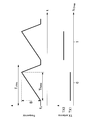
- FIG. 6 is an explanatory diagram showing a relationship between chirp by a local oscillator of the FMCW TDMA MIMO radar apparatus 100 and timing of selecting transmission antennas 140a and 140b by switches 131a and 131b.
- FIG. 6 is an explanatory diagram showing a relationship between chirp by a local oscillator of the FMCW TDMA MIMO radar apparatus 100 and timing of selecting transmission antennas 140a and 140b by switches 131a and 131b.
- 5 is a flowchart showing an operation example of an FMCW TDMA MIMO radar apparatus 100 according to an embodiment of the present disclosure. It is explanatory drawing explaining the effect of the 1st Example of embodiment of this indication. It is explanatory drawing explaining the effect of the 1st Example of embodiment of this indication. It is explanatory drawing which shows the example of the transmission pattern which becomes back-and-forth symmetry centering on the reference time.
- FIG. 5 is a flowchart showing an operation example of an FMCW TDMA MIMO radar apparatus 100 according to an embodiment of the present disclosure. It is explanatory drawing which shows the relationship of the timing which selects transmitting antenna 140a, 140b with switch 131a, 131b.
- FIG. 2 is an explanatory diagram showing an example of a vehicle 2 on which FMCW TDMA MIMO radar devices 100a to 100f are mounted.
- Embodiment of the present disclosure [1.1. Overview] Before describing the embodiments of the present disclosure in detail, an outline of the embodiments of the present disclosure will be described first.
- a TDMA FMCW MIMO radar device may be used as an on-vehicle radar mounted on an automobile.
- FMCW method will be described.
- the FMCW method uses a chirp signal whose frequency is linearly increased or decreased over time as a transmission signal, which is emitted from the transmission antenna, and an echo signal reflected back from the target is captured by the reception antenna.
- the local signal and echo signal are multiplied by the mixer, the frequency of the local signal changes during the round-trip time until the transmitted signal is reflected back by the target and returned to the target.
- FIG. 1 is an explanatory diagram showing a configuration example of an FMCW radar apparatus.
- the local oscillator 12 outputs a local signal whose frequency increases or decreases linearly with time based on the chirp control signal transmitted from the FMCW radar signal processing apparatus 11. .
- the local signal output from the local oscillator 12 is amplified by the power amplifier 13 and then emitted from the transmission antenna 14 as a transmission signal.
- the transmission signal emitted from the transmission antenna 14 is reflected by the target 1.
- the receiving antenna 15 receives an echo signal reflected by the target 1 and returning.
- the echo signal received by the receiving antenna 15 is multiplied by the local signal output from the local oscillator 12 by the mixer 16 to become a beat signal.
- the beat signal is sent to the FMCW radar signal processing device 11 and used for ranging to the target 1.
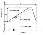
- FIG. 2 is an explanatory diagram illustrating an example of the frequency of the transmission signal, the frequency of the echo signal, and the frequency of the beat signal, which change with time, transmitted by the FMCW radar apparatus 10.
- Frequency of the transmitted signal in the example shown in FIG. 2, increases linearly with time from f 0 to f 0 + BW.
- the echo signal is delayed by a round-trip time ⁇ until the transmission signal is reflected by the target 1 and returned.
- the frequency f B of the beat signal is proportional to the round trip time ⁇ until the transmission signal is reflected by the target and returned. Therefore, it can be said that the FMCW method can know the distance to the target 1 in the measurement period T by knowing the frequency f B of the beat signal.
- the TDMA FMCW MIMO system in addition to the distance measurement based on the FMCW system, sequentially selects one antenna from the M-element transmission array antenna and transmits the chirp signal M times, and simultaneously receives the N-element reception array antenna.
- This is a method for performing angle measurement with improved azimuth resolution by using the fact that it can be regarded as a radar device that receives a virtual array antenna having M * N elements.
- FIG. 3 is an explanatory diagram showing a configuration example of the array antenna of the MIMO radar apparatus.
- the receiving array antenna has N elements and the element spacing is d
- the transmitting array antenna has M elements and the element spacing is N * d.
- the target is in the direction of the angle ⁇ from the Z axis, and is written near the array antenna in FIG. 3 for convenience of explanation. In practice, however, the target is 1000 times or more than the wavelength of 3.9 mm in the 77 GHz band used by the vehicle-mounted radar. The target is located far away. Therefore, the propagation of electromagnetic waves between the array antenna and the target can be approximated by a plane wave.
- FIG. 4 is an explanatory diagram showing a virtual array antenna. The distance between the wavefront 1 and the wavefront 2 is the same as the difference in propagation distance between RX1 and RX4 shown in FIG.
- transmission from the transmission antenna TX2 is equivalent to transmission from the transmission antenna TX1 and reception by the reception antennas RX4, RX5, RX6. Therefore, a virtual array antenna including reception antennas RX1, RX2, RX3, RX4, RX5, and RX6 is configured by transmission from transmission antennas TX1 and TX2.
- Equation 3 is a mode vector of the virtual array antenna corresponding to FIG. 4 and is a Kronecker product of the transmission mode vector and the reception mode vector.
- a radar apparatus that constitutes a virtual array antenna composed of a plurality of elements using a transmission array antenna and a reception array antenna is a MIMO radar apparatus.
- the FMCW TDMA MIMO radar device is a radar device that performs distance measurement and angle measurement by switching a plurality of transmission antennas in a time division manner and sequentially transmitting FMCW chirp signals.
- FIG. 5 is an explanatory diagram showing a configuration example of the FMCW TDMA MIMO radar apparatus.
- the FMCW TDMA MIMO radar apparatus 100 shown in FIG. 5 is the same as the FMCW TDMA MIMO radar signal processing apparatus 110.
- the local oscillator 120, the transmission processing unit 130, transmission antennas 140a and 140b, reception antennas 150a, 150b, and 150c, and a reception processing unit 160 are configured.
- the FMCW TDMA MIMO radar signal processing device 110 is a device that performs various signal processing when the FMCW TDMA MIMO radar device 100 operates. For example, the FMCW TDMA MIMO radar signal processing device 110 sends a chirp control signal to the local oscillator 120 or sends a switching control signal for controlling the output of the transmission signal to the transmission processing unit 130. Further, the FMCW TDMA MIMO radar signal processing device 110 performs distance measurement to the target using the beat signal output from the reception processing unit 160.
- the local oscillator 120 outputs a local signal whose frequency linearly increases or decreases with time based on the chirp control signal transmitted from the FMCW TDMA MIMO radar signal processing device 110.
- the local oscillator 120 sends the generated local signal to the transmission processing unit 130 and the reception processing unit 160.
- the transmission processing unit 130 performs processing for transmitting the local signal transmitted from the local oscillator 120 as a transmission signal from the transmission antennas 140a and 140b.
- the transmission processing unit 130 includes switches 131a and 131b and power amplifiers 132a and 132b.
- the switches 131a and 131b are turned on and off according to the signal from the FMCW TDMA MIMO radar signal processing device 110. Switch. That is, when the switches 131a and 131b are turned on, the local signal is sent to the power amplifiers 132a and 132b.
- the power amplifiers 132a and 132b amplify the local signal sent from the local oscillator 120 by a predetermined amount.
- the transmission antennas 140a and 140b emit the local signals amplified by the power amplifiers 132a and 132b into the air as transmission signals, respectively.
- the transmission antennas 140a and 140b emit the local signals amplified by the power amplifiers 132a and 132b into the air as transmission signals, respectively.
- two transmission antennas 140a and 140b are shown, and the number of switches and power amplifiers in the transmission processing unit 130 corresponds to the number of transmission antennas.
- the receiving antennas 150a, 150b, and 150c receive echo signals that are reflected back from the target.
- three receiving antennas 150a, 150b, and 150c are shown.
- the reception processing unit 160 multiplies the echo signal received by the receiving antennas 150a, 150b, and 150c and the local signal output from the local oscillator 120 to generate a beat signal.
- the reception processing unit 160 includes mixers 161a, 161b, and 161c that multiply the echo signal and the local signal.
- FIG. 6 is an explanatory diagram showing the relationship between the chirp by the local oscillator of the FMCW TDMA MIMO radar apparatus 100 and the timing at which the transmission antennas 140a and 140b are selected by the switches 131a and 131b.
- T Chirp is one period of the chirp
- T Ramp is the chirp ramp time
- f 0 is the chirp start frequency
- B is the chirp bandwidth
- N Chirp is an index representing the chirp context.
- TX1 corresponds to the transmission antenna 140a
- TX2 corresponds to the transmission antenna 140b.
- FIG. 7 is an explanatory diagram showing the position of the target on the coordinate axis.
- the origin of the coordinates in FIG. 7 corresponds to the position of the FMCW TDMA MIMO radar apparatus 100.
- the beat signal received by the virtual array antenna of the FMCW TDMA MIMO radar apparatus 100 is expressed by Equation 4.
- A is the amplitude of the beat signal
- f R is the beat frequency proportional to the distance R 0 as shown in Equation 5
- f D is the Doppler frequency proportional to the velocity V as shown in Equation 6.
- the term including the velocity V in Equation 4 is a term representing the Doppler phase shift, and the target moves at the velocity V during T Chirp , which is the time difference between TX1 (transmitting antenna 140a) and TX2 (transmitting antenna 140b). The phase difference caused by a slight change in the propagation distance is shown.
- f R in Equation 5 also includes a term including the speed V.
- a round trip occurs in a short time of about 10 us at T Chirp. Since the change in distance is only 2 mm, which is very small compared to the ranging resolution of the FMCW TDMA MIMO radar apparatus 100, this term can be ignored.
- Equation 4 the term of Doppler phase shift in Equation 4 can be rewritten as shown in Equation 7 and Equation 8 by shifting to the mode vector of the transmitting array antenna.
- the FMCW TDMA MIMO radar device modulates the directional angle measurement accuracy because the mode vector of the transmitting array antenna is modulated with the Doppler phase shift proportional to the speed when the target is moving. It is clear to do.
- a virtual array antenna of M * N ⁇ L elements is configured so that at least L antenna elements overlap, and the Doppler phase is determined from the phase difference of beat signals received by the overlapping antenna elements.
- Techniques for seeking and compensating for shifts are disclosed.
- the Doppler phase shift of the entire virtual array antenna is compensated from beat signals received by a small number of overlapping antenna elements, the azimuth estimation accuracy is greatly affected by slight noise.
- the azimuth resolution is lowered.
- the present disclosure has intensively studied a technique capable of excluding the influence based on the movement of the target in the FMCW TDMA MIMO radar apparatus easily and without reducing accuracy. .
- the present disclosurer repeatedly performs transmission in the FMCW TDMA MIMO radar apparatus so that the antenna element numbers of the transmitting array antenna are symmetrical in the longitudinal direction around the reference time.
- the technology has been devised to synthesize the beat signal at the reference time from the beat signal after the reference time and the beat signal after the reference time to eliminate the influence based on the movement of the target.
- the FMCW TDMA MIMO radar signal processing apparatus 110 appropriately sets the on / off timings of the switches 131a and 131b, thereby eliminating the influence based on the movement of the target.
- the purpose is that. More specifically, the switches 131a and 131b are turned on and off from the FMCW TDMA MIMO radar signal processing device 110 so that transmission is repeatedly performed so that the antenna element numbers of the transmission array antenna are symmetrical in the longitudinal direction with respect to the reference time. Set the timing.
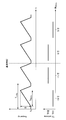
- FIG. 8 is an explanatory diagram showing the relationship between the chirp by the local oscillator of the FMCW TDMA MIMO radar apparatus 100 and the timing at which the transmission antennas 140a and 140b are selected by the switches 131a and 131b.
- T Chirp is one period of the chirp
- T Ramp is the chirp ramp time
- f 0 is the chirp start frequency
- B is the chirp bandwidth
- N Chirp is an index representing the chirp context.
- the FMCW TDMA MIMO radar signal processing device 110 selects the transmission antennas 140b, 140a, 140a, and 140b in order in order to transmit at a certain reference time, and switches 131a and 131b. Control on / off. As described above, it will be described that the influence based on the movement of the target can be excluded by repeatedly performing transmission so that the antenna element numbers of the transmission array antenna are symmetrical in the front-rear direction around the reference time.
- the mode vectors of the transmission array antenna of the first beat signal S B1 and the first beat signal S B1 are expressed by Equation 9 and Equation 10, respectively.
- A1 represents the amplitude.
- the mode vectors of the transmission array antenna of the second beat signal S B2 and the second beat signal S B2 are expressed by Equation 11 and Equation 12, respectively.
- A2 represents the amplitude.
- the FMCW TDMA MIMO radar signal processing device 110 performs signal processing for synthesizing the beat signal at the reference time using the first beat signal SB1 and the second beat signal SB2. Specifically, as shown in Formula 13, the FMCW TDMA MIMO radar signal processing apparatus 110 calculates the average amplitude of the first beat signal S B1 and the second beat signal S B2 for each transmission antenna, Signal processing for synthesizing the beat signal at the reference time is performed from the phase of the sum of the beat signal S B1 and the second beat signal S B2 .
- Equations 10 and 12 are complex conjugates. Therefore, when the sum of the two mode vectors is taken as shown in Equation 16, the imaginary part of the Doppler phase is canceled and only the cosine component of the real part remains in the amplitude.
- the FMCW TDMA MIMO radar signal processing device 110 can compensate the Doppler phase.
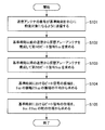
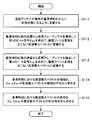
- FIG. 9 is a flowchart showing an operation example of the FMCW TDMA MIMO radar apparatus 100 according to the embodiment of the present disclosure.
- an operation example of the FMCW TDMA MIMO radar apparatus 100 according to the embodiment of the present disclosure will be described with reference to FIG.
- the FMCW TDMA MIMO radar apparatus 100 transmits the transmission antenna number so that it is a target before and after the reference time (step S101). This transmission processing is executed by the transmission processing unit 130 upon receiving a switching control signal from the FMCW TDMA MIMO radar signal processing device 110.
- FMCW TDMA MIMO radar device 100 constitutes a virtual antenna array from the reference time previous transmission, determining a first beat signal S B1 (step S102).
- the FMCW TDMA MIMO radar device 100 constitutes a virtual array antenna from the transmission of the subsequent reference time, determining a second beat signal S B2 (step S103).
- the order of obtaining the first beat signal S B1 and the second beat signal S B2 may of course be reversed.
- FMCW TDMA MIMO radar device 100 is to average the amplitude of the first beat signal S B1 the amplitude of the second beat signal S B2, determine the amplitude of the beat signal at the reference time (step S104). Further, the FMCW TDMA MIMO radar apparatus 100 obtains the phase of the beat signal at the reference time from the phase of the sum of the first beat signal S B1 and the second beat signal S B2 (step S105). Of course, the order of obtaining the amplitude and phase of the beat signal at the reference time may be reversed.
- the FMCW TDMA MIMO radar apparatus 100 can perform Doppler phase compensation and eliminate the influence of the target motion by executing such a series of operations.
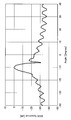
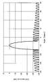
- FIG. 10 shows an orientation spectrum when there is no Doppler phase compensation
- FIG. 11 shows an orientation when the FMCW TDMA MIMO radar apparatus 100 according to the embodiment of the present disclosure compensates for Doppler phase.
- the spectrum is shown.
- the FMCW TDMA MIMO radar apparatus 100 can compensate for the Doppler phase and exclude the influence of the movement of the target.
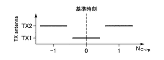
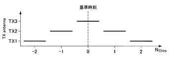
- 12A to 12F are explanatory diagrams showing examples of transmission patterns that are symmetrical in the front-rear direction with respect to the reference time when the transmission array antenna has two elements and three elements.
- 12A to 12D are examples of transmission patterns when the transmission antenna is two elements
- FIGS. 12E to 12F are examples of transmission patterns when the transmission antenna is three elements.
- the transmission pattern is not limited to that shown in FIGS. 12A to 12F.
- the transmission pattern may be a transmission pattern transmitted from any of the transmission antennas across the reference time, and the reference time as shown in FIGS. 12C to 12D. The transmission pattern may not be transmitted from any of the transmission antennas.
- the beat signals S B1 and S B2 are time signals, but this signal processing can be similarly performed in the frequency spectrum.
- the FMCW radar apparatus as a general procedure, a beat signal is subjected to discrete Fourier transform and converted into a frequency spectrum. Therefore, it is very preferable to remove the Doppler phase in the frequency domain.
- the signal processing is performed after discretely Fourier-beating the beat signals S B1 and S B2 as shown in Equation 18 below.
- FIG. 13 is a flowchart illustrating an operation example of the FMCW TDMA MIMO radar apparatus 100 according to the embodiment of the present disclosure.
- an operation example of the FMCW TDMA MIMO radar apparatus 100 according to the embodiment of the present disclosure will be described with reference to FIG.
- the FMCW TDMA MIMO radar apparatus 100 transmits the transmission antenna number so that it is the target before and after the reference time (step S111). This transmission processing is executed by the transmission processing unit 130 upon receiving a switching control signal from the FMCW TDMA MIMO radar signal processing device 110.
- the FMCW TDMA MIMO radar apparatus 100 constructs a virtual array antenna from transmissions before the reference time, obtains the first beat signal SB1, and performs discrete Fourier transform to convert it to a frequency spectrum (step S112). . Further, the FMCW TDMA MIMO radar apparatus 100 constructs a virtual array antenna from transmissions after the reference time, obtains the second beat signal SB2 , and further performs discrete Fourier transform to convert it into a frequency spectrum (step S113). The order of obtaining the first beat signal S B1 and the second beat signal S B2 may of course be reversed.
- the FMCW TDMA MIMO radar apparatus 100 obtains the amplitude of the frequency spectrum of the beat signal at the reference time by averaging the amplitude of the first beat signal S B1 and the frequency spectrum of the second beat signal S B2 (Ste S114). Further, the FMCW TDMA MIMO radar apparatus 100 obtains the phase of the frequency spectrum of the beat signal at the reference time from the phase of the sum of the frequency spectra of the first beat signal S B1 and the second beat signal S B2 (step S115). Of course, the order of obtaining the amplitude and phase of the frequency spectrum of the beat signal at the reference time may be reversed.
- the FMCW TDMA MIMO radar apparatus 100 can compensate for Doppler phase in the frequency domain and exclude the influence of the movement of the target. .
- FIG. 14 is a flowchart showing an operation example of the FMCW TDMA MIMO radar apparatus 100 according to the embodiment of the present disclosure.
- an operation example of the FMCW TDMA MIMO radar apparatus 100 according to the embodiment of the present disclosure will be described with reference to FIG.
- the FMCW TDMA MIMO radar apparatus 100 transmits the transmission antenna number so that it is a target before and after the reference time (step S121). This transmission processing is executed by the transmission processing unit 130 upon receiving a switching control signal from the FMCW TDMA MIMO radar signal processing device 110.
- FMCW TDMA MIMO radar device 100 constitutes a virtual antenna array from the reference time previous transmission, determining a first beat signal S B1 (step S122).
- the FMCW TDMA MIMO radar device 100 constitutes a virtual array antenna from the transmission of the subsequent reference time, determining a second beat signal S B2 (step S123).
- the order of obtaining the first beat signal S B1 and the second beat signal S B2 may of course be reversed.
- the FMCW TDMA MIMO radar apparatus 100 obtains a third beat signal S B3 by averaging the first beat signal S B1 and the second beat signal S B2 (step S124).
- the FMCW TDMA MIMO radar apparatus 100 determines whether the amplitude of the third beat signal S B3 is equal to or less than X times the amplitude of the first beat signal S B1 (X is a predetermined threshold value) (step S125).
- the FMCW TDMA MIMO radar apparatus 100 obtains the amplitude of the beat signal at the reference time by averaging the amplitude of the first beat signal S B1 and the amplitude of the second beat signal S B2 (step S126). Further, the FMCW TDMA MIMO radar apparatus 100 obtains the phase of the beat signal at the reference time from the phase of the sum of the first beat signal S B1 and the second beat signal S B2 (step S127).
- the order of obtaining the amplitude and phase of the beat signal at the reference time may be reversed.
- step S125 determines whether the amplitude of the third beat signal S B3 is not more than X times the amplitude of the first beat signal S B1 (X is a predetermined threshold).
- step S125, Yes The FMCW TDMA MIMO radar apparatus 100 advances the processing using either the first beat signal S B1 or the second beat signal S B2 as the beat signal at the reference time (step S128).
- FIG. 15 is an explanatory diagram illustrating a relationship between timings at which the transmission antennas 140a and 140b are selected by the switches 131a and 131b.
- the FMCW TDMA MIMO radar apparatus 100 can output the beat signal at the same time interval as before.
- the FMCW TDMA MIMO radar apparatus 100 Since the FMCW TDMA MIMO radar apparatus 100 according to the embodiment of the present disclosure can eliminate the influence based on the movement of the target, the FMCW TDMA MIMO radar apparatus 100 supports safe driving of a vehicle that requires high-precision ranging.
- the present invention can be preferably applied to a radar apparatus of the system.
- FIG. 16 is an explanatory diagram showing an example of a vehicle 2 on which FMCW TDMA MIMO radar devices 100a to 100f are mounted.
- the FMCW TDMA MIMO radar devices 100a to 100f shown in FIG. 16 are assumed to be any of the FMCW TDMA MIMO radar devices 100 according to the embodiment of the present disclosure described above.
- the FMCW TDMA MIMO radar devices 100a to 100f are any of short-range, medium-range, and long-range radar devices, and are used to detect objects around the vehicle 2.
- the FMCW TDMA MIMO radar apparatus 100 By applying the FMCW TDMA MIMO radar apparatus 100 according to the embodiment of the present disclosure as a radar apparatus of a system that supports safe driving of an automobile, it is possible to contribute to higher performance of the system. .
- transmission is repeatedly performed so that the antenna element numbers of the transmission array antenna are symmetric in the front-rear direction around a predetermined reference time, and the beat signal before the reference time and the reference It is possible to provide the FMCW TDMA MIMO radar apparatus 100 capable of excluding the influence based on the movement of the target by synthesizing the beat signal at the reference time from the beat signals after the time.
- each step in the processing executed by each device in this specification does not necessarily have to be processed in chronological order in the order described as a sequence diagram or flowchart.
- each step in the processing executed by each device may be processed in an order different from the order described as the flowchart, or may be processed in parallel.
- M (M ⁇ 2) transmit antennas; N (N ⁇ 1) receive antennas; A local oscillator that oscillates a local signal; A transmission processing unit that selects one of the transmission antennas and transmits a transmission signal based on the local signal; and From the echo signal reflected by the target of the transmission signal received by the reception antenna and the local signal, a reception processing unit that outputs a beat signal; A signal processing unit for performing signal processing on the beat signal; With The transmission processing unit performs transmission from the transmission antenna by sequentially switching the antenna element numbers so that the antenna element numbers are symmetric with respect to a reference time, The signal processing unit synthesizes a beat signal at the reference time from a first beat signal received by the receiving antenna before the reference time and a second beat signal received after the reference time.
- the signal processing unit obtains the amplitude of the beat signal at the reference time by averaging the amplitude of the first beat signal and the amplitude of the second beat signal, and the phase of the first beat signal and the first beat signal
- the radar apparatus according to (1) wherein the phase of the beat signal at the reference time is obtained by adding the phases of the two beat signals.
- the signal processing unit is configured to generate a beat signal at the reference time from a first frequency spectrum obtained by performing a discrete Fourier transform on the first beat signal and a second frequency spectrum obtained by performing a discrete Fourier transform on the second beat signal.
- the radar apparatus according to (1) which synthesizes a frequency spectrum.
- the signal processing unit uses the first beat signal or the second beat signal as the reference
- the radar device according to any one of (1) to (3), wherein the radar signal is a beat signal at time.
- the predetermined value is a predetermined ratio of an amplitude of the first beat signal or an amplitude of the second beat signal.
- a signal processing unit that performs signal processing on an echo signal that is transmitted from M transmission antennas (M ⁇ 2) and reflected by a target of a transmission signal based on a local signal, and a beat signal that is generated from the local signal With The signal processing unit is sequentially switched so that the antenna element number is symmetric in the longitudinal direction around the reference time, and transmitted from the transmission antenna.
- a signal processing device that synthesizes a beat signal at the reference time from a first beat signal received by the receiving antenna before the reference time and a second beat signal received after the reference time.
Landscapes
- Engineering & Computer Science (AREA)
- Radar, Positioning & Navigation (AREA)
- Remote Sensing (AREA)
- Physics & Mathematics (AREA)
- Computer Networks & Wireless Communication (AREA)
- General Physics & Mathematics (AREA)
- Electromagnetism (AREA)
- Radar Systems Or Details Thereof (AREA)
- Traffic Control Systems (AREA)
- Variable-Direction Aerials And Aerial Arrays (AREA)
Abstract
【課題】TDMA FMCW MIMOレーダ装置において、移動物標のドップラ位相シフトを補償して方位推定精度を向上することが可能なことが可能なレーダ装置を提供する。 【解決手段】基準時刻を中心としてアンテナ素子の番号が前後対称となるように順次切り替えて送信アンテナから送信を行い、基準時刻以前に受信アンテナが受信した第1のビート信号と、基準時刻以降に受信した第2のビート信号とから、基準時刻におけるビート信号を合成する、レーダ装置が提供される。
Description
本開示は、レーダ装置、信号処理装置及び信号処理方法に関する。
自動車に搭載される車載レーダとして、TDMA(Time-Division Multiple-Access) FMCW(Frequency-Modulated Continuous-Wave) MIMO(Multiple-Input Multiple-Output)レーダ装置が用いられることがある。
FMCW方式とは、時間とともに周波数を線形に増加または減少させたチャープ信号を送信信号として送信アンテナから放出し、物標で反射して戻ってきたエコー信号を受信アンテナで捉え、送信信号と同じ周波数のローカル信号とエコー信号とをミキサで乗算するときに、送信された信号が物標で反射して戻ってくるまでの往復時間の間にローカル信号の周波数が変化して、物標までの距離に比例した周波数のビート信号が生じることを利用して測距をおこなう方式である。そしてTDMA FMCW MIMO方式とは、FMCW方式による測距に加えて、M素子の送信アレーアンテナから一つのアンテナを順次選択してチャープ信号をM回送信し、N素子の受信アレーアンテナで同時に受信することによりM*N素子の仮想アレーアンテナで受信するレーダ装置とみなすことができることを利用して、方位分解能を向上させた測角をおこなう方式である。
TDMA FMCW MIMOレーダ装置は、物標とレーダ装置とが相対的に移動している場合に、ドップラ位相シフトによって測角精度が劣化することが知られている、そのため、例えば非特許文献1では、少なくともL箇所のアンテナ素子が重複するようにM*N-L素子の仮想アレーアンテナを構成して、重複したアンテナ素子で受信したビート信号の位相差からドップラ位相シフトを求めて補償する技術が開示されている。
C. M. Schmid, R. Feger, C. Pfeffer, A. Stelzer. "Motion Compensation and Efficient Array Design for TDMA FMCW MIMO Radar Systems," Eucap 2012.
しかし非特許文献1で開示された方法では、重複させた数少ないアンテナ素子で受信したビート信号から仮想アレーアンテナ全体のドップラ位相シフトの補償をおこなうため僅かなノイズによって方位推定精度が大きく影響される。さらに、アンテナ素子を重複させたことで、仮想アレーアンテナの素子数が減少するため、方位分解能が低下する。
そこで本開示では、TDMA FMCW MIMOレーダ装置において、移動物標のドップラ位相シフトを補償して方位推定精度を向上することが可能なことが可能な、新規かつ改良されたレーダ装置、信号処理装置及び信号処理方法を提案する。
本開示によれば、M個(M≧2)の送信アンテナと、N個(N≧1)の受信アンテナと、ローカル信号を発振するローカル発振器と、前記ローカル信号に基づく送信信号をいずれか一つの前記送信アンテナを選択して送信する送信処理部と、前記受信アンテナが受信した、前記送信信号の物標での反射によるエコー信号と、前記ローカル信号とから、ビート信号を出力する受信処理部と、前記ビート信号に対する信号処理を行う信号処理部と、を備え、前記送信処理部は、基準時刻を中心としてアンテナ素子の番号が前後対称となるように順次切り替えて前記送信アンテナから送信を行い、前記信号処理部は、前記基準時刻以前に前記受信アンテナが受信した第1のビート信号と、前記基準時刻以降に受信した第2のビート信号とから、前記基準時刻におけるビート信号を合成する、レーダ装置が提供される。
また本開示によれば、M個(M≧2)の送信アンテナから送信された、ローカル信号に基づく送信信号の物標での反射によるエコー信号と、前記ローカル信号とから生成されるビート信号に対する信号処理を行う信号処理部を備え、前記信号処理部は、基準時刻を中心としてアンテナ素子の番号が前後対称となるように順次切り替えて前記送信アンテナから送信させ、前記基準時刻以前に前記受信アンテナが受信した第1のビート信号と、前記基準時刻以降に受信した第2のビート信号とから、前記基準時刻におけるビート信号を合成する、信号処理装置が提供される。
また本開示によれば、基準時刻を中心としてアンテナ素子の番号が前後対称となるように順次切り替えてM個(M≧2)の送信アンテナから、ローカル信号に基づく送信信号を送信させることと、前記送信アンテナから送信された前記送信信号の物標での反射によるエコー信号と、前記ローカル信号とから生成されるビート信号に対する信号処理を行うことと、を含み、前記信号処理を行うことは、前記基準時刻以前に前記受信アンテナが受信した第1のビート信号と、前記基準時刻以降に受信した第2のビート信号とから、前記基準時刻におけるビート信号を合成することを含む、信号処理方法が提供される。
以上説明したように本開示によれば、TDMA FMCW MIMOレーダ装置において、移動物標のドップラ位相シフトを補償して方位推定精度を向上することが可能なことが可能な、新規かつ改良されたレーダ装置、信号処理装置及び信号処理方法を提供することが出来る。
なお、上記の効果は必ずしも限定的なものではなく、上記の効果とともに、または上記の効果に代えて、本明細書に示されたいずれかの効果、または本明細書から把握され得る他の効果が奏されてもよい。
以下に添付図面を参照しながら、本開示の好適な実施の形態について詳細に説明する。なお、本明細書及び図面において、実質的に同一の機能構成を有する構成要素については、同一の符号を付することにより重複説明を省略する。
なお、説明は以下の順序で行うものとする。
1.本開示の実施の形態
1.1.概要
1.2.第1実施例
1.3.第2実施例
1.4.第3実施例
1.5.第4実施例
1.6.応用例
2.まとめ
1.本開示の実施の形態
1.1.概要
1.2.第1実施例
1.3.第2実施例
1.4.第3実施例
1.5.第4実施例
1.6.応用例
2.まとめ
<1.本開示の実施の形態>
[1.1.概要]
本開示の実施の形態について詳細に説明する前に、まず本開示の実施の形態の概要について説明する。
[1.1.概要]
本開示の実施の形態について詳細に説明する前に、まず本開示の実施の形態の概要について説明する。
上述したように、自動車に搭載される車載レーダとして、TDMA FMCW MIMOレーダ装置が用いられることがある。まずはFMCW方式について説明する。
FMCW方式とは、時間とともに周波数を線形に増加または減少させたチャープ信号を送信信号として送信アンテナから放出し、物標で反射して戻ってきたエコー信号を受信アンテナで捉え、送信信号と同じ周波数のローカル信号とエコー信号とをミキサで乗算するときに、送信された信号が物標で反射して戻ってくるまでの往復時間の間にローカル信号の周波数が変化して、物標までの距離に比例した周波数のビート信号が生じることを利用して測距をおこなう方式である。
図1は、FMCWレーダ装置の構成例を示す説明図である。図1に示したようにFMCWレーダ装置10において、ローカル発振器12は、FMCWレーダ信号処理装置11から送出されるチャープ制御信号に基づいて、時間とともに周波数が線形に増加または減少するローカル信号を出力する。ローカル発振器12が出力したローカル信号は、パワーアンプ13で増幅された後に、送信アンテナ14から送信信号として放出される。
送信アンテナ14から放出された送信信号は、物標1で反射される。受信アンテナ15は、物標1で反射されて戻ってくるエコー信号を受信する。受信アンテナ15が受信したエコー信号は、ローカル発振器12が出力したローカル信号とミキサ16で乗算されてビート信号となる。ビート信号は、FMCWレーダ信号処理装置11に送られて、物標1までの測距に用いられる。
図2は、時間とともに変化する、FMCWレーダ装置10が送信する送信信号の周波数、エコー信号の周波数、ビート信号の周波数の例を示す説明図である。送信信号の周波数は、図2に示した例では、f0からf0+BWまで時間とともに線形に増加する。エコー信号は、送信信号が物標1で反射して戻ってくるまでの往復時間τだけ遅れている。ビート信号の周波数fBは、送信信号が物標で反射して戻ってくるまでの往復時間τに比例する。従ってFMCW方式は、ビート信号の周波数fBを知ることで、測定周期Tにおける物標1までの距離を知ることが出来る方式と言える。
そしてTDMA FMCW MIMO方式とは、FMCW方式による測距に加えて、M素子の送信アレーアンテナから一つのアンテナを順次選択してチャープ信号をM回送信し、N素子の受信アレーアンテナで同時に受信することによりM*N素子の仮想アレーアンテナで受信するレーダ装置とみなすことができることを利用して、方位分解能を向上させた測角をおこなう方式である。
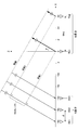
図3は、MIMOレーダ装置のアレーアンテナの構成例を示す説明図である。図3に示した例では、受信アレーアンテナはN素子で素子間隔がdであり、送信アレーアンテナはM素子で素子間隔がN*dである。物標は、Z軸から角度θの方位にあり、図3では説明の便宜上アレーアンテナの近くに書いてあるが、実際は、車載レーダが使用する77GHz帯の波長3.9mmに対して1000倍以上の遠方に物標が位置している。従って、アレーアンテナと物標との間の電磁波の伝搬は平面波で近似することができる。
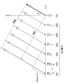
まず、送信アンテナTX1から送信を行なうと、送信信号が波面1から物標までを伝搬し、エコー信号は物標から受信アンテナRX1,RX2,RX3まで伝搬する。次に、送信アンテナTX2から送信を行なうと、送信信号は波面2から物標まで伝搬し、エコー信号は物標から受信アンテナRX1,RX2,RX3まで伝搬する。送信アンテナTX2から送信した場合は、物標までの伝搬距離が、波面1と波面2との距離N*d*sin(θ)だけ短くなる。図4は、仮想アレーアンテナを示す説明図であり、この波面1と波面2との距離は、図4に示すRX1とRX4の伝搬距離の差と同じである。つまり、送信アンテナTX2から送信した場合は、送信アンテナTX1から送信して受信アンテナRX4,RX5,RX6で受信したことに等価になる。従って、送信アンテナTX1,TX2からの送信で、受信アンテナRX1,RX2,RX3,RX4,RX5,RX6からなる仮想アレーアンテナが構成される。
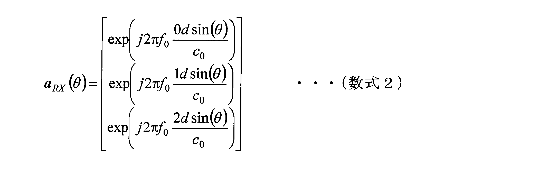
ここで,図3のM=2,N=3の場合に対応する送信アレーアンテナと受信アレーアンテナのモードベクトルを数式1と数式2に示す。f0は送信信号の周波数、dは受信アンテナの間、θは物標の方位、c0は光速である。また、数式3は図4に対応する仮想アレーアンテナのモードベクトルであり、送信モードベクトルと受信モードベクトルのクロネッカー積になる。


このように、送信アレーアンテナと受信アレーアンテナを用いて、複数の素子からなる仮想アレーアンテナを構成するレーダ装置がMIMOレーダ装置である。特に、複数の送信アンテナを時分割で切り替えてFMCW方式のチャープ信号を順次送信して測距と測角をおこなうレーダ装置がFMCW TDMA MIMOレーダ装置である。
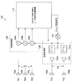
図5は、FMCW TDMA MIMOレーダ装置の構成例を示す説明図である。図5に示したFMCW TDMA MIMOレーダ装置100は、FMCW TDMA MIMOレーダ信号処理装置110と。ローカル発振器120と、送信処理部130と、送信アンテナ140a、140bと、受信アンテナ150a、150b、150cと、受信処理部160と、を含んで構成される。
FMCW TDMA MIMOレーダ信号処理装置110は、FMCW TDMA MIMOレーダ装置100の動作に際し様々な信号処理を実施する装置である。例えばFMCW TDMA MIMOレーダ信号処理装置110は、ローカル発振器120に対してチャープ制御信号を送出したり、送信処理部130に対して送信信号の出力を制御するスイッチング制御信号を送出したりする。またFMCW TDMA MIMOレーダ信号処理装置110は、受信処理部160から出力されるビート信号を用いて物標までの測距を行う。
ローカル発振器120は、FMCW TDMA MIMOレーダ信号処理装置110から送出されるチャープ制御信号に基づいて、時間とともに周波数が線形に増加または減少するローカル信号を出力する。ローカル発振器120は、生成したローカル信号を送信処理部130及び受信処理部160に送る。
送信処理部130は、ローカル発振器120から送られたローカル信号を、送信アンテナ140a、140bから送信信号として送出させるための処理を行う。送信処理部130は、スイッチ131a、131bと、パワーアンプ132a、132bと、を含んで構成される、スイッチ131a、131bは、FMCW TDMA MIMOレーダ信号処理装置110からの信号に応じてオン、オフするスイッチである。すなわち、スイッチ131a、131bがオンされていると、ローカル信号はパワーアンプ132a、132bに送られる。パワーアンプ132a、132bは、ローカル発振器120から送られたローカル信号を所定量増幅させる。
送信アンテナ140a、140bは、それぞれ、パワーアンプ132a、132bで増幅されたローカル信号を、送信信号として空中に放出する。図5に示した例では2つの送信アンテナ140a、140bを示しており、送信処理部130におけるスイッチやパワーアンプの数は、この送信アンテナの数に対応している。
受信アンテナ150a、150b、150cは、物標で反射して戻ってくるエコー信号を受信する。図5に示した例では3つの受信アンテナ150a、150b、150cを示している。
受信処理部160は、受信アンテナ150a、150b、150cが受信したエコー信号と、ローカル発振器120が出力したローカル信号とを乗算してビート信号を生成する。受信処理部160は、エコー信号と、ローカル信号とを乗算するミキサ161a、161b、161cからなる。
図6は、FMCW TDMA MIMOレーダ装置100のローカル発振器によるチャープと、スイッチ131a、131bで送信アンテナ140a、140bを選択するタイミングとの関係を示す説明図である。TChirpはチャープの1周期、TRampはチャープのランプ時間、f0はチャープ開始周波数、Bはチャープ帯域幅、NChirpはチャープの前後関係をあらわすインデックスである。またTX1は送信アンテナ140aに対応し、TX2は送信アンテナ140bに対応する。
一般に、物標が動いている場合は、ドップラ位相シフトが生じることが知られている。図7は、物標の位置を座標軸上で示した説明図である。図7の座標の原点はFMCW TDMA MIMOレーダ装置100の位置に相当する。図7に示すように、座標(X0,Z0)、方位θ、距離R0に一つの物標があり、θ方向から速度VでFMCW TDMA MIMOレーダ装置100に接近している場合を想定。この場合、FMCW TDMA MIMOレーダ装置100の仮想アレーアンテナで受信されるビート信号は数式4になる。Aはビート信号の振幅、fRは数式5に示すように距離R0に比例するビート周波数、fDは数式6に示すように速度Vに比例するドップラ周波数である。



数式4における速度Vを含む項がドップラ位相シフトを表す項であり、TX1(送信アンテナ140a)とTX2(送信アンテナ140b)で送信をおこなう時間差であるTChirpの間、物標が速度Vで移動し、伝搬距離がわずかに変化したことで生じた位相差を表している。
なお、数式5のfRにも速度Vを含む項があるが、仮に速度Vが100m/s(=360km/h)の高速であっても、TChirpが10us程度の短時間の場合では往復距離の変化は僅か2mmであり、FMCW TDMA MIMOレーダ装置100の測距分解能に比べて非常に小さいため、この項は無視できる。
従って、数式4のドップラ位相シフトの項は、送信アレーアンテナのモードベクトルに移項して、数式7と数式8に示すように書き換えることができる。

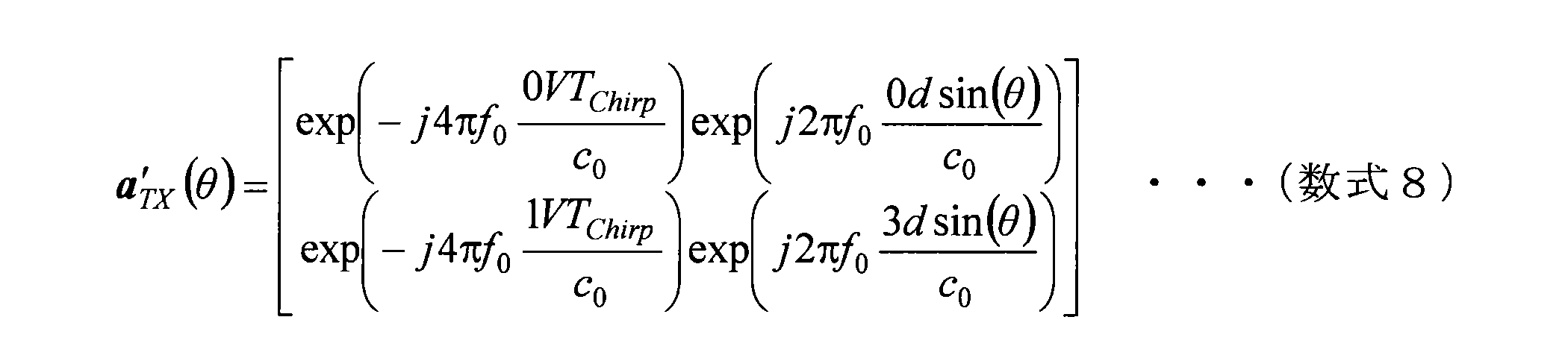
この数式7と数式8から、FMCW TDMA MIMOレーダ装置は、物標が動いている場合に送信アレーアンテナのモードベクトルが速度に比例したドップラ位相シフトで変調されるため、方位の測角精度が劣化することが明らかである。
そのため、例えば非特許文献1では、少なくともL箇所のアンテナ素子が重複するようにM*N-L素子の仮想アレーアンテナを構成して、重複したアンテナ素子で受信したビート信号の位相差からドップラ位相シフトを求めて補償する技術が開示されている。しかし非特許文献1で開示された方法では、重複させた数少ないアンテナ素子で受信したビート信号から仮想アレーアンテナ全体のドップラ位相シフトの補償をおこなうため僅かなノイズによって方位推定精度が大きく影響される。さらに、アンテナ素子を重複させたことで、仮想アレーアンテナの素子数が減少するため、方位分解能が低下する。
そこで本件開示者は、上述した点に鑑みて、FMCW TDMA MIMOレーダ装置において簡易にかつ精度を落とすことなく、物標の動きに基づいた影響を除外することが可能な技術について鋭意検討を行った。その結果、本件開示者は、以下で説明するように、FMCW TDMA MIMOレーダ装置において、基準時刻を中心として送信アレーアンテナのアンテナ素子の番号が前後対称となるように繰り返し送信をおこない、基準時刻以前のビート信号と基準時刻以降のビート信号から、基準時刻におけるビート信号を合成することで物標の動きに基づいた影響を除外することが可能な技術を考案するに至った。
以上、本開示の実施の形態の概要について説明した。続いて、本開示の実施の形態について詳細に説明する。
[1.2.第1実施例]
まず、本開示の実施の形態の第1実施例について説明する。第1実施例を説明するにあたり、FMCW TDMA MIMOレーダ装置の構成例は図5に示したものと同じものを用いる。
まず、本開示の実施の形態の第1実施例について説明する。第1実施例を説明するにあたり、FMCW TDMA MIMOレーダ装置の構成例は図5に示したものと同じものを用いる。
本開示の実施の形態の第1実施例では、FMCW TDMA MIMOレーダ信号処理装置110によるスイッチ131a、131bのオン、オフのタイミングを適切に設定することで、標の動きに基づいた影響を除外することを目的としている。より具体的には、基準時刻を中心として送信アレーアンテナのアンテナ素子の番号が前後対称となるように繰り返し送信をおこなうよう、FMCW TDMA MIMOレーダ信号処理装置110からスイッチ131a、131bのオン、オフのタイミングを設定する。
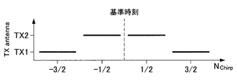
図8は、FMCW TDMA MIMOレーダ装置100のローカル発振器によるチャープと、スイッチ131a、131bで送信アンテナ140a、140bを選択するタイミングとの関係を示す説明図である。TChirpはチャープの1周期、TRampはチャープのランプ時間、f0はチャープ開始周波数、Bはチャープ帯域幅、NChirpはチャープの前後関係をあらわすインデックスである。
図8に示したように、FMCW TDMA MIMOレーダ信号処理装置110は、ある基準時刻が中心となるように、送信アンテナ140b、140a、140a、140bの順に選択して送信するようにスイッチ131a、131bのオン、オフを制御する。このように基準時刻を中心として送信アレーアンテナのアンテナ素子の番号が前後対称となるように繰り返し送信をおこなうことで、物標の動きに基づいた影響を除外することができることを説明する。
はじめに、基準時刻以前のNChirp=-3/2と、NChirp=-1/2の2回の送信で構成された仮想アレーアンテナで受信したビート信号を第1のビート信号SB1とする。第1のビート信号SB1および第1のビート信号SB1の送信アレーアンテナのモードベクトルは、それぞれ数式9と数式10になる。A1は振幅を表す。


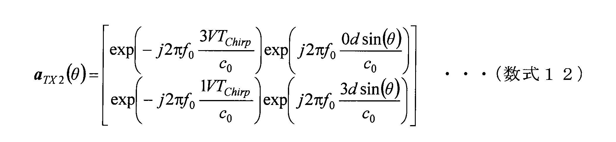
次に、基準時刻以降のNChirp=1/2とNChirp=3/2の2回の送信で構成された仮想アレーアンテナで受信したビート信号を第2のビート信号SB2とする。第2のビート信号SB2および第2のビート信号SB2の送信アレーアンテナのモードベクトルは、それぞれ数式11と数式12になる。A2は振幅を表す。

FMCW TDMA MIMOレーダ信号処理装置110は、第1のビート信号SB1及び第2のビート信号SB2を用いて、基準時刻におけるビート信号を合成する信号処理を行う。具体的には、FMCW TDMA MIMOレーダ信号処理装置110は、数式13に示すように、送信アンテナ毎に第1のビート信号SB1と第2のビート信号SB2の振幅の平均と、第1のビート信号SB1と第2のビート信号SB2の和の位相から、基準時刻におけるビート信号を合成する信号処理をおこなう。

第1のビート信号SB1と第2のビート信号SB2の振幅の平均と、第1のビート信号SB1と第2のビート信号SB2の和の位相から、基準時刻におけるビート信号を合成することで物標の動きの影響が除外される理由を説明する。
数式13のSB1とSB2に、数式9と数式11をそれぞれ代入して整理すると、数式14および数式15になる。


ここで数式15に含まれる振幅A1、A2は、短時間では変化しないために等しいとみなすことができる。そして、数式10と数式12は複素共役である。従って、数式16に示すように2つのモードベクトルの和をとると、ドップラ位相の虚部はキャンセルされて実部のコサイン成分だけが振幅に残る。

数式16のコサイン成分がゼロよりも大きければ、数式15の演算が可能である。従って、数式17に示す速度領域であれば、本実施形態に係るFMCW TDMA MIMOレーダ信号処理装置110は、ドップラ位相を補償することができる。

図9は、本開示の実施の形態に係るFMCW TDMA MIMOレーダ装置100の動作例を示す流れ図である。以下、図9を用いて本開示の実施の形態に係るFMCW TDMA MIMOレーダ装置100の動作例について説明する。
まず、FMCW TDMA MIMOレーダ装置100は、送信アンテナの番号が、基準時刻を中心に前後対象となるように送信する(ステップS101)。この送信処理は、送信処理部130がFMCW TDMA MIMOレーダ信号処理装置110からのスイッチング制御信号を受けて実行する。
続いてFMCW TDMA MIMOレーダ装置100は、基準時刻以前の送信から仮想アレーアンテナを構成して、第1のビート信号SB1を求める(ステップS102)。またFMCW TDMA MIMOレーダ装置100は、基準時刻以降の送信から仮想アレーアンテナを構成して、第2のビート信号SB2を求める(ステップS103)。第1のビート信号SB1と第2のビート信号SB2を求める順序はもちろん逆でも良い。
続いてFMCW TDMA MIMOレーダ装置100は、第1のビート信号SB1の振幅と第2のビート信号SB2の振幅を平均して、基準時刻におけるビート信号の振幅を求める(ステップS104)。またFMCW TDMA MIMOレーダ装置100は、第1のビート信号SB1と第2のビート信号SB2の和の位相から、基準時刻におけるビート信号の位相を求める(ステップS105)。基準時刻におけるビート信号の振幅と位相を求める順序はもちろん逆でも良い。
本開示の実施の形態に係るFMCW TDMA MIMOレーダ装置100は、このような一連の動作を実行することで、ドップラ位相の補償を行って物標の動きの影響を除外することができる。
以下の表1に示したパラメータを用いて、第1実施例の効果を説明する。図10、図11は、本開示の実施の形態の第1実施例の効果を説明する説明図である。図10は、ドップラ位相の補償が無い場合の方位スペクトルを示したものであり、図11は、本開示の実施の形態に係るFMCW TDMA MIMOレーダ装置100がドップラ位相の補償を行った場合の方位スペクトルを示したものである。

図10に示したように、ドップラ位相の補償が無い場合では、方位スペクトルの波形が乱れているのに対し、図11に示したように、ドップラ位相の補償がある場合では、方位スペクトルの波形が乱れていないのが分かる。従って、本開示の実施の形態に係るFMCW TDMA MIMOレーダ装置100は、ドップラ位相の補償を行って物標の動きの影響を除外することが出来る。
図12A~12Fは、送信アレーアンテナが2素子と3素子の場合に、基準時刻を中心に前後対称になるような送信パターンの例を示す説明図である。図12A~12Dは送信アンテナが2素子の場合の送信パターンの例で有り、図12E~12Fは送信アンテナが3素子の場合の送信パターンの例で有る。もちろん、送信パターンは図12A~12Fに示したものに限定されるものでは無い。また、図12A~12B、図12E~12Fに示したように、基準時刻を跨いでいずれかの送信アンテナから送信される送信パターンであってもよく、図12C~12Dに示したように基準時刻においてはいずれの送信アンテナからも送信されていないような送信パターンであってもよい。
[1.3.第2実施例]
続いて第2実施例について説明する。第1実施例で示したドップラ位相を除去する信号処理は、ビート信号SB1、SB2を時間信号としているが、この信号処理は周波数スペクトルでも同様におこなうことが可能である。FMCWレーダ装置では、一般的な手順としてビート信号を離散フーリエ変換して周波数スペクトルに変換することが行われているので、周波数領域でドップラ位相を除去することは非常に好適である。
続いて第2実施例について説明する。第1実施例で示したドップラ位相を除去する信号処理は、ビート信号SB1、SB2を時間信号としているが、この信号処理は周波数スペクトルでも同様におこなうことが可能である。FMCWレーダ装置では、一般的な手順としてビート信号を離散フーリエ変換して周波数スペクトルに変換することが行われているので、周波数領域でドップラ位相を除去することは非常に好適である。
周波数領域でドップラ位相を除去する場合、下記の数式18に示すようにビート信号SB1、SB2を離散フーリエしてから信号処理を行う。

図13は、本開示の実施の形態に係るFMCW TDMA MIMOレーダ装置100の動作例を示す流れ図である。以下、図13を用いて本開示の実施の形態に係るFMCW TDMA MIMOレーダ装置100の動作例について説明する。
まず、FMCW TDMA MIMOレーダ装置100は、送信アンテナの番号が、基準時刻を中心に前後対象となるように送信する(ステップS111)。この送信処理は、送信処理部130がFMCW TDMA MIMOレーダ信号処理装置110からのスイッチング制御信号を受けて実行する。
続いてFMCW TDMA MIMOレーダ装置100は、基準時刻以前の送信から仮想アレーアンテナを構成して、第1のビート信号SB1を求め、さらに離散フーリエ変換をおこなって周波数スペクトルに変換する(ステップS112)。またFMCW TDMA MIMOレーダ装置100は、基準時刻以降の送信から仮想アレーアンテナを構成して、第2のビート信号SB2を求め、さらに離散フーリエ変換をおこなって周波数スペクトルに変換する(ステップS113)。第1のビート信号SB1と第2のビート信号SB2を求める順序はもちろん逆でも良い。
続いてFMCW TDMA MIMOレーダ装置100は、第1のビート信号SB1の振幅と第2のビート信号SB2の周波数スペクトルの振幅を平均して、基準時刻におけるビート信号の周波数スペクトルの振幅を求める(ステップS114)。またFMCW TDMA MIMOレーダ装置100は、第1のビート信号SB1と第2のビート信号SB2の周波数スペクトルの和の位相から、基準時刻におけるビート信号の周波数スペクトルの位相を求める(ステップS115)。基準時刻におけるビート信号の周波数スペクトルの振幅と位相を求める順序はもちろん逆でも良い。
本開示の実施の形態に係るFMCW TDMA MIMOレーダ装置100は、このような一連の動作を実行することで、周波数領域でドップラ位相の補償を行って物標の動きの影響を除外することができる。
[1.4.第3実施例]
第1実施例で示した信号処理は、数式16のコサイン成分がゼロになる場合に、数式15の角度を求める演算が不可能になり、基準時刻におけるビート信号を合成できなくなる。そこで第3実施例では、第1のビート信号SB1と第2のビート信号SB2を平均して第3のビート信号SB3を求めて、この第3のビート信号SB3の振幅と第1のビート信号SB1の振幅を比較して、振幅比が所定の閾値以下(例えば1/10以下)に小さくなる場合は信号処理をおこなわないことにする。
第1実施例で示した信号処理は、数式16のコサイン成分がゼロになる場合に、数式15の角度を求める演算が不可能になり、基準時刻におけるビート信号を合成できなくなる。そこで第3実施例では、第1のビート信号SB1と第2のビート信号SB2を平均して第3のビート信号SB3を求めて、この第3のビート信号SB3の振幅と第1のビート信号SB1の振幅を比較して、振幅比が所定の閾値以下(例えば1/10以下)に小さくなる場合は信号処理をおこなわないことにする。
図14は、本開示の実施の形態に係るFMCW TDMA MIMOレーダ装置100の動作例を示す流れ図である。以下、図14を用いて本開示の実施の形態に係るFMCW TDMA MIMOレーダ装置100の動作例について説明する。
まず、FMCW TDMA MIMOレーダ装置100は、送信アンテナの番号が、基準時刻を中心に前後対象となるように送信する(ステップS121)。この送信処理は、送信処理部130がFMCW TDMA MIMOレーダ信号処理装置110からのスイッチング制御信号を受けて実行する。
続いてFMCW TDMA MIMOレーダ装置100は、基準時刻以前の送信から仮想アレーアンテナを構成して、第1のビート信号SB1を求める(ステップS122)。またFMCW TDMA MIMOレーダ装置100は、基準時刻以降の送信から仮想アレーアンテナを構成して、第2のビート信号SB2を求める(ステップS123)。第1のビート信号SB1と第2のビート信号SB2を求める順序はもちろん逆でも良い。
続いてFMCW TDMA MIMOレーダ装置100は、第1のビート信号SB1と第2のビート信号SB2を平均して第3のビート信号SB3を求める(ステップS124)。
続いてFMCW TDMA MIMOレーダ装置100は、第3のビート信号SB3の振幅が、第1のビート信号SB1の振幅のX倍(Xは所定の閾値)以下かどうか判断する(ステップS125)。
ステップS125の判断の結果、続いて第3のビート信号SB3の振幅が、第1のビート信号SB1の振幅のX倍(Xは所定の閾値)以下でなければ(ステップS125、No)、続いてFMCW TDMA MIMOレーダ装置100は、第1のビート信号SB1の振幅と第2のビート信号SB2の振幅を平均して、基準時刻におけるビート信号の振幅を求める(ステップS126)。またFMCW TDMA MIMOレーダ装置100は、第1のビート信号SB1と第2のビート信号SB2の和の位相から、基準時刻におけるビート信号の位相を求める(ステップS127)。基準時刻におけるビート信号の振幅と位相を求める順序はもちろん逆でも良い。
一方、ステップS125の判断の結果、続いて第3のビート信号SB3の振幅が、第1のビート信号SB1の振幅のX倍(Xは所定の閾値)以下であれば(ステップS125、Yes)、FMCW TDMA MIMOレーダ装置100は、第1のビート信号SB1または第2のビート信号SB2のいずれかを、基準時刻におけるビート信号として処理を進める(ステップS128)。
[1.5.第4実施例]
第1実施例で示した信号処理は、例えば図8に示すように4回の送信で基準時刻におけるビート信号が得られる。一方、従来のFMCW TDMA MIMOレーダ装置は、図6に示したように2回の送信でビート信号が得られる。従って、第1実施例で示した信号処理は従来の信号処理に比べて2倍の時間を必要とする。
第1実施例で示した信号処理は、例えば図8に示すように4回の送信で基準時刻におけるビート信号が得られる。一方、従来のFMCW TDMA MIMOレーダ装置は、図6に示したように2回の送信でビート信号が得られる。従って、第1実施例で示した信号処理は従来の信号処理に比べて2倍の時間を必要とする。
そこで、この第4実施例では、信号処理に要する時間を短縮する例を示す。図15は、スイッチ131a、131bで送信アンテナ140a、140bを選択するタイミングの関係を示す説明図である。図15に示すように、FMCW TDMA MIMOレーダ装置100は、NChirp=0,1,2,3から基準時刻0におけるビート信号を合成し、続いてNChirp=2,3,4,5から基準時刻1におけるビート信号を合成し、さらに続いてNChirp=4,5,6,7から基準時刻2におけるビート信号を合成する。
このようにことでビート信号を合成することで、本開示の実施の形態に係るFMCW TDMA MIMOレーダ装置100は、従来と同じ時間間隔でビート信号を出力することが可能になる。
[1.6.応用例]
本開示の実施の形態に係るFMCW TDMA MIMOレーダ装置100は、物標の動きに基づいた影響を除外することができるため、高い精度での測距が求められる、自動車の安全な走行を支援するシステムのレーダ装置に好適に適用することが可能である。
本開示の実施の形態に係るFMCW TDMA MIMOレーダ装置100は、物標の動きに基づいた影響を除外することができるため、高い精度での測距が求められる、自動車の安全な走行を支援するシステムのレーダ装置に好適に適用することが可能である。
図16は、FMCW TDMA MIMOレーダ装置100a~100fが搭載されている車両2の例を示す説明図である。図16に示したFMCW TDMA MIMOレーダ装置100a~100fは、上述した本開示の実施の形態に係るFMCW TDMA MIMOレーダ装置100のいずれかであるとする。FMCW TDMA MIMOレーダ装置100a~100fは、短距離、中距離、長距離用のいずれかのレーダ装置であり、車両2の周囲の物体などの検知に用いられる。
このような、自動車の安全な走行を支援するシステムのレーダ装置として、本開示の実施の形態に係るFMCW TDMA MIMOレーダ装置100を適用することで、上記システムの高性能化に寄与することができる。
<2.まとめ>
以上説明したように本開示の実施の形態によれば、所定の基準時刻を中心として送信アレーアンテナのアンテナ素子の番号が前後対称となるように繰り返し送信をおこない、基準時刻以前のビート信号と基準時刻以降のビート信号から、基準時刻におけるビート信号を合成することで物標の動きに基づいた影響を除外することが可能なFMCW TDMA MIMOレーダ装置100を提供することが出来る。
以上説明したように本開示の実施の形態によれば、所定の基準時刻を中心として送信アレーアンテナのアンテナ素子の番号が前後対称となるように繰り返し送信をおこない、基準時刻以前のビート信号と基準時刻以降のビート信号から、基準時刻におけるビート信号を合成することで物標の動きに基づいた影響を除外することが可能なFMCW TDMA MIMOレーダ装置100を提供することが出来る。
本明細書の各装置が実行する処理における各ステップは、必ずしもシーケンス図またはフローチャートとして記載された順序に沿って時系列に処理する必要はない。例えば、各装置が実行する処理における各ステップは、フローチャートとして記載した順序と異なる順序で処理されても、並列的に処理されてもよい。
また、各装置に内蔵されるCPU、ROMおよびRAMなどのハードウェアを、上述した各装置の構成と同等の機能を発揮させるためのコンピュータプログラムも作成可能である。また、該コンピュータプログラムを記憶させた記憶媒体も提供されることが可能である。また、機能ブロック図で示したそれぞれの機能ブロックをハードウェアまたはハードウェア回路で構成することで、一連の処理をハードウェアまたはハードウェア回路で実現することもできる。
以上、添付図面を参照しながら本開示の好適な実施形態について詳細に説明したが、本開示の技術的範囲はかかる例に限定されない。本開示の技術分野における通常の知識を有する者であれば、特許請求の範囲に記載された技術的思想の範疇内において、各種の変更例または修正例に想到し得ることは明らかであり、これらについても、当然に本開示の技術的範囲に属するものと了解される。
また、本明細書に記載された効果は、あくまで説明的または例示的なものであって限定的ではない。つまり、本開示に係る技術は、上記の効果とともに、または上記の効果に代えて、本明細書の記載から当業者には明らかな他の効果を奏しうる。
なお、以下のような構成も本開示の技術的範囲に属する。
(1)
M個(M≧2)の送信アンテナと、
N個(N≧1)の受信アンテナと、
ローカル信号を発振するローカル発振器と、
前記ローカル信号に基づく送信信号をいずれか一つの前記送信アンテナを選択して送信する送信処理部と、
前記受信アンテナが受信した、前記送信信号の物標での反射によるエコー信号と、前記ローカル信号とから、ビート信号を出力する受信処理部と、
前記ビート信号に対する信号処理を行う信号処理部と、
を備え、
前記送信処理部は、基準時刻を中心としてアンテナ素子の番号が前後対称となるように順次切り替えて前記送信アンテナから送信を行い、
前記信号処理部は、前記基準時刻以前に前記受信アンテナが受信した第1のビート信号と、前記基準時刻以降に受信した第2のビート信号とから、前記基準時刻におけるビート信号を合成する、レーダ装置。
(2)
前記信号処理部は、前記第1のビート信号の振幅と前記第2のビート信号の振幅とを平均して前記基準時刻におけるビート信号の振幅を求め、前記第1のビート信号の位相と前記第2のビート信号の位相とを加算して前記基準時刻におけるビート信号の位相を求める、前記(1)に記載のレーダ装置。
(3)
前記信号処理部は、前記第1のビート信号を離散フーリエ変換した第1の周波数スペクトルと、前記第2のビート信号を離散フーリエ変換した第2の周波数スペクトルとから、前記基準時刻におけるビート信号の周波数スペクトルを合成する、前記(1)に記載のレーダ装置。
(4)
前記信号処理部は、前記第1のビート信号の振幅と前記第2のビート信号の振幅との平均が所定値以下であれば、前記第1のビート信号または前記第2のビート信号を前記基準時刻におけるビート信号とする、前記(1)~(3)のいずれかに記載のレーダ装置。
(5)
前記所定値は、前記第1のビート信号の振幅または前記第2のビート信号の振幅の所定の割合である、前記(4)に記載のレーダ装置。
(6)
車両に搭載される、前記(1)~(5)のいずれかに記載のレーダ装置。
(7)
M個(M≧2)の送信アンテナから送信された、ローカル信号に基づく送信信号の物標での反射によるエコー信号と、前記ローカル信号とから生成されるビート信号に対する信号処理を行う信号処理部を備え、
前記信号処理部は、基準時刻を中心としてアンテナ素子の番号が前後対称となるように順次切り替えて前記送信アンテナから送信させ、
前記基準時刻以前に前記受信アンテナが受信した第1のビート信号と、前記基準時刻以降に受信した第2のビート信号とから、前記基準時刻におけるビート信号を合成する、信号処理装置。
(8)
基準時刻を中心としてアンテナ素子の番号が前後対称となるように順次切り替えてM個(M≧2)の送信アンテナから、ローカル信号に基づく送信信号を送信させることと、
前記送信アンテナから送信された前記送信信号の物標での反射によるエコー信号と、前記ローカル信号とから生成されるビート信号に対する信号処理を行うことと、
を含み、
前記信号処理を行うことは、前記基準時刻以前に前記受信アンテナが受信した第1のビート信号と、前記基準時刻以降に受信した第2のビート信号とから、前記基準時刻におけるビート信号を合成することを含む、信号処理方法。
(1)
M個(M≧2)の送信アンテナと、
N個(N≧1)の受信アンテナと、
ローカル信号を発振するローカル発振器と、
前記ローカル信号に基づく送信信号をいずれか一つの前記送信アンテナを選択して送信する送信処理部と、
前記受信アンテナが受信した、前記送信信号の物標での反射によるエコー信号と、前記ローカル信号とから、ビート信号を出力する受信処理部と、
前記ビート信号に対する信号処理を行う信号処理部と、
を備え、
前記送信処理部は、基準時刻を中心としてアンテナ素子の番号が前後対称となるように順次切り替えて前記送信アンテナから送信を行い、
前記信号処理部は、前記基準時刻以前に前記受信アンテナが受信した第1のビート信号と、前記基準時刻以降に受信した第2のビート信号とから、前記基準時刻におけるビート信号を合成する、レーダ装置。
(2)
前記信号処理部は、前記第1のビート信号の振幅と前記第2のビート信号の振幅とを平均して前記基準時刻におけるビート信号の振幅を求め、前記第1のビート信号の位相と前記第2のビート信号の位相とを加算して前記基準時刻におけるビート信号の位相を求める、前記(1)に記載のレーダ装置。
(3)
前記信号処理部は、前記第1のビート信号を離散フーリエ変換した第1の周波数スペクトルと、前記第2のビート信号を離散フーリエ変換した第2の周波数スペクトルとから、前記基準時刻におけるビート信号の周波数スペクトルを合成する、前記(1)に記載のレーダ装置。
(4)
前記信号処理部は、前記第1のビート信号の振幅と前記第2のビート信号の振幅との平均が所定値以下であれば、前記第1のビート信号または前記第2のビート信号を前記基準時刻におけるビート信号とする、前記(1)~(3)のいずれかに記載のレーダ装置。
(5)
前記所定値は、前記第1のビート信号の振幅または前記第2のビート信号の振幅の所定の割合である、前記(4)に記載のレーダ装置。
(6)
車両に搭載される、前記(1)~(5)のいずれかに記載のレーダ装置。
(7)
M個(M≧2)の送信アンテナから送信された、ローカル信号に基づく送信信号の物標での反射によるエコー信号と、前記ローカル信号とから生成されるビート信号に対する信号処理を行う信号処理部を備え、
前記信号処理部は、基準時刻を中心としてアンテナ素子の番号が前後対称となるように順次切り替えて前記送信アンテナから送信させ、
前記基準時刻以前に前記受信アンテナが受信した第1のビート信号と、前記基準時刻以降に受信した第2のビート信号とから、前記基準時刻におけるビート信号を合成する、信号処理装置。
(8)
基準時刻を中心としてアンテナ素子の番号が前後対称となるように順次切り替えてM個(M≧2)の送信アンテナから、ローカル信号に基づく送信信号を送信させることと、
前記送信アンテナから送信された前記送信信号の物標での反射によるエコー信号と、前記ローカル信号とから生成されるビート信号に対する信号処理を行うことと、
を含み、
前記信号処理を行うことは、前記基準時刻以前に前記受信アンテナが受信した第1のビート信号と、前記基準時刻以降に受信した第2のビート信号とから、前記基準時刻におけるビート信号を合成することを含む、信号処理方法。
100 FMCW TDMA MIMOレーダ装置
Claims (8)
- M個(M≧2)の送信アンテナと、
N個(N≧1)の受信アンテナと、
ローカル信号を発振するローカル発振器と、
前記ローカル信号に基づく送信信号をいずれか一つの前記送信アンテナを選択して送信する送信処理部と、
前記受信アンテナが受信した、前記送信信号の物標での反射によるエコー信号と、前記ローカル信号とから、ビート信号を出力する受信処理部と、
前記ビート信号に対する信号処理を行う信号処理部と、
を備え、
前記送信処理部は、基準時刻を中心としてアンテナ素子の番号が前後対称となるように順次切り替えて前記送信アンテナから送信を行い、
前記信号処理部は、前記基準時刻以前に前記受信アンテナが受信した第1のビート信号と、前記基準時刻以降に受信した第2のビート信号とから、前記基準時刻におけるビート信号を合成する、レーダ装置。 - 前記信号処理部は、前記第1のビート信号の振幅と前記第2のビート信号の振幅とを平均して前記基準時刻におけるビート信号の振幅を求め、前記第1のビート信号の位相と前記第2のビート信号の位相とを加算して前記基準時刻におけるビート信号の位相を求める、請求項1に記載のレーダ装置。
- 前記信号処理部は、前記第1のビート信号を離散フーリエ変換した第1の周波数スペクトルと、前記第2のビート信号を離散フーリエ変換した第2の周波数スペクトルとから、前記基準時刻におけるビート信号の周波数スペクトルを合成する、請求項1に記載のレーダ装置。
- 前記信号処理部は、前記第1のビート信号の振幅と前記第2のビート信号の振幅との平均が所定値以下であれば、前記第1のビート信号または前記第2のビート信号を前記基準時刻におけるビート信号とする、請求項1に記載のレーダ装置。
- 前記所定値は、前記第1のビート信号の振幅または前記第2のビート信号の振幅の所定の割合である、請求項4に記載のレーダ装置。
- 車両に搭載される、請求項1に記載のレーダ装置。
- M個(M≧2)の送信アンテナから送信された、ローカル信号に基づく送信信号の物標での反射によるエコー信号と、前記ローカル信号とから生成されるビート信号に対する信号処理を行う信号処理部を備え、
前記信号処理部は、基準時刻を中心としてアンテナ素子の番号が前後対称となるように順次切り替えて前記送信アンテナから送信させ、
前記基準時刻以前に前記受信アンテナが受信した第1のビート信号と、前記基準時刻以降に受信した第2のビート信号とから、前記基準時刻におけるビート信号を合成する、信号処理装置。 - 基準時刻を中心としてアンテナ素子の番号が前後対称となるように順次切り替えてM個(M≧2)の送信アンテナから、ローカル信号に基づく送信信号を送信させることと、
前記送信アンテナから送信された前記送信信号の物標での反射によるエコー信号と、前記ローカル信号とから生成されるビート信号に対する信号処理を行うことと、
を含み、
前記信号処理を行うことは、前記基準時刻以前に前記受信アンテナが受信した第1のビート信号と、前記基準時刻以降に受信した第2のビート信号とから、前記基準時刻におけるビート信号を合成することを含む、信号処理方法。
Priority Applications (3)
| Application Number | Priority Date | Filing Date | Title |
|---|---|---|---|
| CN201780064657.6A CN109923433B (zh) | 2016-10-25 | 2017-09-11 | 雷达装置、信号处理装置和信号处理方法 |
| US16/340,902 US11119203B2 (en) | 2016-10-25 | 2017-09-11 | Radar device, signal processor, and signal processing method |
| US17/387,173 US11852712B2 (en) | 2016-10-25 | 2021-07-28 | Radar device, signal processor, and signal processing method |
Applications Claiming Priority (2)
| Application Number | Priority Date | Filing Date | Title |
|---|---|---|---|
| JP2016208483A JP2018072014A (ja) | 2016-10-25 | 2016-10-25 | レーダ装置、信号処理装置及び信号処理方法 |
| JP2016-208483 | 2016-10-25 |
Related Child Applications (2)
| Application Number | Title | Priority Date | Filing Date |
|---|---|---|---|
| US16/340,902 A-371-Of-International US11119203B2 (en) | 2016-10-25 | 2017-09-11 | Radar device, signal processor, and signal processing method |
| US17/387,173 Continuation US11852712B2 (en) | 2016-10-25 | 2021-07-28 | Radar device, signal processor, and signal processing method |
Publications (1)
| Publication Number | Publication Date |
|---|---|
| WO2018079097A1 true WO2018079097A1 (ja) | 2018-05-03 |
Family
ID=62023277
Family Applications (1)
| Application Number | Title | Priority Date | Filing Date |
|---|---|---|---|
| PCT/JP2017/032625 Ceased WO2018079097A1 (ja) | 2016-10-25 | 2017-09-11 | レーダ装置、信号処理装置及び信号処理方法 |
Country Status (4)
| Country | Link |
|---|---|
| US (2) | US11119203B2 (ja) |
| JP (1) | JP2018072014A (ja) |
| CN (1) | CN109923433B (ja) |
| WO (1) | WO2018079097A1 (ja) |
Cited By (4)
| Publication number | Priority date | Publication date | Assignee | Title |
|---|---|---|---|---|
| JP2020056589A (ja) * | 2018-09-28 | 2020-04-09 | パナソニックIpマネジメント株式会社 | レーダ装置、及び、レーダ方法 |
| CN112513667A (zh) * | 2018-07-31 | 2021-03-16 | 株式会社村田制作所 | 雷达装置 |
| CN115601995A (zh) * | 2022-09-30 | 2023-01-13 | 中汽创智科技有限公司(Cn) | 弱势交通参与者的通行方法、装置、设备及存储介质 |
| WO2023218632A1 (ja) * | 2022-05-13 | 2023-11-16 | 株式会社日立製作所 | レーダ装置および物標検知方法 |
Families Citing this family (33)
| Publication number | Priority date | Publication date | Assignee | Title |
|---|---|---|---|---|
| US10330773B2 (en) * | 2016-06-16 | 2019-06-25 | Texas Instruments Incorporated | Radar hardware accelerator |
| JP2018072014A (ja) * | 2016-10-25 | 2018-05-10 | ソニーセミコンダクタソリューションズ株式会社 | レーダ装置、信号処理装置及び信号処理方法 |
| CA3045522C (en) | 2016-12-06 | 2023-10-03 | Berkshire Grey, Inc. | Systems and methods for providing for the processing of objects in vehicles |
| IL250253B (en) | 2017-01-24 | 2021-10-31 | Arbe Robotics Ltd | A method for separating targets and echoes from noise, in radar signals |
| IL255982A (en) | 2017-11-29 | 2018-01-31 | Arbe Robotics Ltd | Detection, mitigation and prevention of mutual interference between fixed water radars in vehicles |
| IL259190A (en) * | 2018-05-07 | 2018-06-28 | Arbe Robotics Ltd | System and method of fmcw time multiplexed mimo imaging radar using multi-band chirps |
| JP7152193B2 (ja) * | 2018-06-07 | 2022-10-12 | 株式会社デンソーテン | レーダ装置 |
| KR102628655B1 (ko) * | 2018-06-29 | 2024-01-24 | 삼성전자주식회사 | 레이더 구동 장치 및 방법 |
| IL260696A (en) | 2018-07-19 | 2019-01-31 | Arbe Robotics Ltd | Method and device for structured self-testing of radio frequencies in a radar system |
| IL260695A (en) | 2018-07-19 | 2019-01-31 | Arbe Robotics Ltd | Method and device for eliminating waiting times in a radar system |
| IL260694A (en) | 2018-07-19 | 2019-01-31 | Arbe Robotics Ltd | Method and device for two-stage signal processing in a radar system |
| CN112534298A (zh) * | 2018-08-07 | 2021-03-19 | 株式会社村田制作所 | 雷达装置 |
| IL261636A (en) | 2018-09-05 | 2018-10-31 | Arbe Robotics Ltd | Deflected MIMO antenna array for vehicle imaging radars |
| JP7266207B2 (ja) * | 2018-09-28 | 2023-04-28 | パナソニックIpマネジメント株式会社 | レーダ装置、及び、レーダ方法 |
| DE102019125991A1 (de) * | 2018-09-28 | 2020-04-02 | Panasonic Intellectual Property Management Co., Ltd. | Radar-Vorrichtung und Radar-Verfahren |
| KR102733511B1 (ko) | 2018-12-04 | 2024-11-25 | 삼성전자주식회사 | 레이더 데이터를 처리하는 장치 및 방법 |
| EP3882661A4 (en) | 2018-12-12 | 2021-12-15 | Huawei Technologies Co., Ltd. | SIGNAL PROCESSING, RADAR SYSTEM AND VEHICLE |
| JP7023247B2 (ja) * | 2019-02-04 | 2022-02-21 | 日立Astemo株式会社 | レーダ装置 |
| WO2020261525A1 (ja) * | 2019-06-28 | 2020-12-30 | 日本電気株式会社 | レーダ装置、イメージング方法およびイメージングプログラム |
| EP4711816A2 (en) * | 2019-08-19 | 2026-03-18 | Shenzhen Yinwang Intelligent Technologies Co., Ltd. | Signal transmission method and apparatus, signal processing method and apparatus, and radar system |
| IL271269A (en) | 2019-12-09 | 2021-06-30 | Arbe Robotics Ltd | Radom for a planar antenna for car radar |
| KR20210082946A (ko) | 2019-12-26 | 2021-07-06 | 삼성전자주식회사 | 레이더 신호 처리 장치 및 방법 |
| KR20210101957A (ko) * | 2020-02-11 | 2021-08-19 | 삼성전자주식회사 | 레이더 시스템에서의 객체 속도 검출 방법 및 장치 |
| WO2021181658A1 (ja) * | 2020-03-13 | 2021-09-16 | 三菱電機株式会社 | レーダ装置 |
| US11693107B2 (en) * | 2020-09-29 | 2023-07-04 | Steradian Semiconductors Private Limited | System, device and method for efficient MIMO radar |
| IL278587A (en) | 2020-11-09 | 2022-06-01 | Arbe Robotics Ltd | Estimating an efficient direction of arrival using a low degree approximation |
| US11860297B2 (en) * | 2021-03-08 | 2024-01-02 | GM Global Technology Operations LLC | High resolution unambiguous radar |
| CN113204017B (zh) * | 2021-03-16 | 2022-11-04 | 西安电子科技大学 | 一种基于lfmcw的mimo雷达信号处理方法 |
| CN113945902B (zh) * | 2021-12-20 | 2022-03-01 | 南京隼眼电子科技有限公司 | 雷达的通道运动相位补偿方法、装置、设备及存储介质 |
| CN115127640B (zh) * | 2022-06-08 | 2023-06-20 | 中国地质环境监测院(自然资源部地质灾害技术指导中心) | 泥石流水位提取方法及系统 |
| US20240377503A1 (en) * | 2023-04-27 | 2024-11-14 | Mediatek Inc. | Applying port diversity of virtual array for improving sensing capability with joint communication links |
| US20250172679A1 (en) * | 2023-11-23 | 2025-05-29 | Richwave Technology Corp. | Transceiving method of signals and radar apparatus |
| TWI894700B (zh) * | 2023-11-23 | 2025-08-21 | 立積電子股份有限公司 | 訊號收發方法及雷達裝置 |
Citations (4)
| Publication number | Priority date | Publication date | Assignee | Title |
|---|---|---|---|---|
| JPH08136647A (ja) * | 1994-11-08 | 1996-05-31 | Honda Motor Co Ltd | Fm−cw方式マルチビームレーダー装置 |
| WO2008015883A1 (en) * | 2006-08-04 | 2008-02-07 | Murata Manufacturing Co., Ltd. | Radar target detecting method, and radar device using the method |
| US20140347211A1 (en) * | 2013-05-24 | 2014-11-27 | Robert Bosch Gmbh | Method for operating a mimo radar |
| US20150295628A1 (en) * | 2014-04-10 | 2015-10-15 | Robert Bosch Gmbh | Method for determining a time multiplexing sequence for a mimo radar |
Family Cites Families (15)
| Publication number | Priority date | Publication date | Assignee | Title |
|---|---|---|---|---|
| DE10142171A1 (de) * | 2001-08-29 | 2003-03-20 | Bosch Gmbh Robert | Radaranordnung |
| JP4566572B2 (ja) * | 2004-02-04 | 2010-10-20 | 三菱電機株式会社 | 車載レーダ装置 |
| JP2006003303A (ja) * | 2004-06-21 | 2006-01-05 | Fujitsu Ten Ltd | レーダ装置 |
| EP1777549B1 (en) * | 2005-10-24 | 2012-10-03 | Mitsubishi Electric Information Technology Centre Europe B.V. | Object ranging |
| US7719469B2 (en) * | 2006-10-06 | 2010-05-18 | Cairos Technologies Ag | Device and method for position measurement by means of linear doppler shifts generated |
| JP2010071865A (ja) * | 2008-09-19 | 2010-04-02 | Fujitsu Ten Ltd | 信号処理装置、及びレーダ装置。 |
| CN102121989B (zh) * | 2010-01-08 | 2013-01-30 | 清华大学 | 一种同时测量高速运动目标的速度和距离的方法 |
| JP5610983B2 (ja) * | 2010-11-01 | 2014-10-22 | 三菱電機株式会社 | レーダ装置 |
| JP5554688B2 (ja) * | 2010-11-19 | 2014-07-23 | 株式会社デンソー | レーダ装置 |
| DE102010064346A1 (de) * | 2010-12-29 | 2012-07-05 | Robert Bosch Gmbh | Radarsensor für Kraftfahrzeuge |
| JP5679904B2 (ja) * | 2011-05-18 | 2015-03-04 | 三菱電機株式会社 | 画像レーダ装置 |
| CN102798842B (zh) * | 2012-07-16 | 2014-03-12 | 西安电子科技大学 | 前视阵列雷达的俯仰-慢时间空时二维自适应处理方法 |
| DE102013209736A1 (de) * | 2013-05-24 | 2014-11-27 | Robert Bosch Gmbh | Verfahren zur Bewertung von Hindernissen in einem Fahrerassistenzsystem für Kraftfahrzeuge |
| KR102207567B1 (ko) * | 2013-11-13 | 2021-01-26 | 현대모비스 주식회사 | 차량용 레이더 및 이의 탐지 성능 개선 방법 |
| JP2018072014A (ja) * | 2016-10-25 | 2018-05-10 | ソニーセミコンダクタソリューションズ株式会社 | レーダ装置、信号処理装置及び信号処理方法 |
-
2016
- 2016-10-25 JP JP2016208483A patent/JP2018072014A/ja active Pending
-
2017
- 2017-09-11 US US16/340,902 patent/US11119203B2/en active Active
- 2017-09-11 CN CN201780064657.6A patent/CN109923433B/zh active Active
- 2017-09-11 WO PCT/JP2017/032625 patent/WO2018079097A1/ja not_active Ceased
-
2021
- 2021-07-28 US US17/387,173 patent/US11852712B2/en active Active
Patent Citations (4)
| Publication number | Priority date | Publication date | Assignee | Title |
|---|---|---|---|---|
| JPH08136647A (ja) * | 1994-11-08 | 1996-05-31 | Honda Motor Co Ltd | Fm−cw方式マルチビームレーダー装置 |
| WO2008015883A1 (en) * | 2006-08-04 | 2008-02-07 | Murata Manufacturing Co., Ltd. | Radar target detecting method, and radar device using the method |
| US20140347211A1 (en) * | 2013-05-24 | 2014-11-27 | Robert Bosch Gmbh | Method for operating a mimo radar |
| US20150295628A1 (en) * | 2014-04-10 | 2015-10-15 | Robert Bosch Gmbh | Method for determining a time multiplexing sequence for a mimo radar |
Cited By (6)
| Publication number | Priority date | Publication date | Assignee | Title |
|---|---|---|---|---|
| CN112513667A (zh) * | 2018-07-31 | 2021-03-16 | 株式会社村田制作所 | 雷达装置 |
| CN112513667B (zh) * | 2018-07-31 | 2024-07-12 | 株式会社村田制作所 | 雷达装置 |
| JP2020056589A (ja) * | 2018-09-28 | 2020-04-09 | パナソニックIpマネジメント株式会社 | レーダ装置、及び、レーダ方法 |
| JP7345099B2 (ja) | 2018-09-28 | 2023-09-15 | パナソニックIpマネジメント株式会社 | レーダ装置、及び、レーダ方法 |
| WO2023218632A1 (ja) * | 2022-05-13 | 2023-11-16 | 株式会社日立製作所 | レーダ装置および物標検知方法 |
| CN115601995A (zh) * | 2022-09-30 | 2023-01-13 | 中汽创智科技有限公司(Cn) | 弱势交通参与者的通行方法、装置、设备及存储介质 |
Also Published As
| Publication number | Publication date |
|---|---|
| JP2018072014A (ja) | 2018-05-10 |
| US11119203B2 (en) | 2021-09-14 |
| US20210356579A1 (en) | 2021-11-18 |
| CN109923433B (zh) | 2022-12-06 |
| US11852712B2 (en) | 2023-12-26 |
| CN109923433A (zh) | 2019-06-21 |
| US20190235066A1 (en) | 2019-08-01 |
Similar Documents
| Publication | Publication Date | Title |
|---|---|---|
| WO2018079097A1 (ja) | レーダ装置、信号処理装置及び信号処理方法 | |
| JP7667331B2 (ja) | 周囲をキャプチャする方法および装置 | |
| JP6818541B2 (ja) | レーダ装置および測位方法 | |
| JP5631763B2 (ja) | Mimoレーダシステム、送信装置、受信装置及びmimoレーダ信号処理方法 | |
| JP5938737B2 (ja) | レーダ装置 | |
| JP6566396B2 (ja) | レーダ装置 | |
| CN109061620B (zh) | 用于运行多输入多输出雷达的方法 | |
| JP6432221B2 (ja) | レーダ装置 | |
| JP6331195B2 (ja) | レーダ装置 | |
| US10247815B1 (en) | Phased array radar system with specular multipath mitigation | |
| CN101430378A (zh) | 实现目标体方向的精确检测的车辆安装方向检测设备 | |
| JP2009121826A (ja) | 電子走査式レーダ装置 | |
| KR20150094240A (ko) | 레이더를 이용한 표적 검출 장치 및 표적을 검출하는 방법 | |
| US12566256B2 (en) | Multiple-input, multiple-output radar system with range-doppler circulating chirps | |
| KR20230140385A (ko) | Mimo 레이더 장치 및 mimo 레이더 방법 | |
| JP6494869B1 (ja) | レーダ装置 | |
| JP6716352B2 (ja) | レーダシステム及びそのレーダ信号処理方法 | |
| JP2020016474A (ja) | レーダシステム及び信号処理方法 | |
| JP7345099B2 (ja) | レーダ装置、及び、レーダ方法 | |
| KR20200109648A (ko) | Fmcw 레이다의 상호간섭 저감 방법 및 장치 | |
| JP6573748B2 (ja) | レーダ装置 | |
| US8188909B2 (en) | Observation signal processing apparatus | |
| JP2006208172A (ja) | 到来時刻推定装置 | |
| KR101052050B1 (ko) | 다수의 레이더를 가간섭적으로 결합하여 이동 표적의 감지율을 향상시키는 방법 및 그 방법이 적용된 레이더 시스템 | |
| JP2012233739A (ja) | レーダ装置 |
Legal Events
| Date | Code | Title | Description |
|---|---|---|---|
| 121 | Ep: the epo has been informed by wipo that ep was designated in this application |
Ref document number: 17866097 Country of ref document: EP Kind code of ref document: A1 |
|
| NENP | Non-entry into the national phase |
Ref country code: DE |
|
| 122 | Ep: pct application non-entry in european phase |
Ref document number: 17866097 Country of ref document: EP Kind code of ref document: A1 |